WO2025142152A1 - 収穫物の搬送システムおよびコンテナ装置 - Google Patents
収穫物の搬送システムおよびコンテナ装置 Download PDFInfo
- Publication number
- WO2025142152A1 WO2025142152A1 PCT/JP2024/039868 JP2024039868W WO2025142152A1 WO 2025142152 A1 WO2025142152 A1 WO 2025142152A1 JP 2024039868 W JP2024039868 W JP 2024039868W WO 2025142152 A1 WO2025142152 A1 WO 2025142152A1
- Authority
- WO
- WIPO (PCT)
- Prior art keywords
- container
- harvest
- container device
- rail
- unit
- Prior art date
- Legal status (The legal status is an assumption and is not a legal conclusion. Google has not performed a legal analysis and makes no representation as to the accuracy of the status listed.)
- Pending
Links
Images




Classifications
-
- A—HUMAN NECESSITIES
- A01—AGRICULTURE; FORESTRY; ANIMAL HUSBANDRY; HUNTING; TRAPPING; FISHING
- A01B—SOIL WORKING IN AGRICULTURE OR FORESTRY; PARTS, DETAILS, OR ACCESSORIES OF AGRICULTURAL MACHINES OR IMPLEMENTS, IN GENERAL
- A01B73/00—Means or arrangements to facilitate transportation of agricultural machines or implements, e.g. folding frames to reduce overall width
-
- A—HUMAN NECESSITIES
- A01—AGRICULTURE; FORESTRY; ANIMAL HUSBANDRY; HUNTING; TRAPPING; FISHING
- A01D—HARVESTING; MOWING
- A01D46/00—Picking of fruits, vegetables, hops, or the like; Devices for shaking trees or shrubs
- A01D46/28—Vintaging machines, i.e. grape harvesting machines
-
- A—HUMAN NECESSITIES
- A01—AGRICULTURE; FORESTRY; ANIMAL HUSBANDRY; HUNTING; TRAPPING; FISHING
- A01D—HARVESTING; MOWING
- A01D46/00—Picking of fruits, vegetables, hops, or the like; Devices for shaking trees or shrubs
- A01D46/30—Robotic devices for individually picking crops
-
- A—HUMAN NECESSITIES
- A01—AGRICULTURE; FORESTRY; ANIMAL HUSBANDRY; HUNTING; TRAPPING; FISHING
- A01D—HARVESTING; MOWING
- A01D90/00—Vehicles for carrying harvested crops with means for selfloading or unloading
- A01D90/10—Unloading means
Definitions
- the system further includes a tank for storing the harvest, positioned below the specified stopping position, and when the container device includes a container in which the harvest is loaded and a transport mechanism for dropping the harvest downward by opening and closing the bottom of the container, the tank may be provided with a receiving port for receiving the harvest dropping from the container.
- the harvested product loaded in the container device at the stopped position can be transferred to the tank.
- the container device in the harvest transport system of any one of (1) to (10) above, if the container device is equipped with a measuring unit that measures the load amount of the harvest to be loaded, it may further be equipped with an output unit that outputs the load amount to the outside. In this case, the load amount of the container device can be recognized from the outside.
- the output unit may output the condition together with the load amount. In this case, the state of the harvested product in the container device can be recognized from outside.
- FIG. 3 Another aspect of the present disclosure is a container device.
- This container device is suspended from a plurality of rails constituting a rail network provided above a field in which crops are grown, and moves along the plurality of rails.
- the container device includes a container in which the harvested product obtained by harvesting the crop is loaded, a movement mechanism that moves the container along the rails, a measurement unit that measures the load of the harvested product loaded in the container, and a control unit that controls the movement mechanism to move the container to a predetermined stopping position located at the edge of the rail network and stop the container there when the load meets a predetermined condition.
- the agricultural work system 1 has a function of controlling (managing) the state of the crop C in the field F, and a function of supporting agricultural work in the field F.
- three mutually orthogonal directions in each drawing are defined as an X direction, a Y direction, and a Z direction.
- the Z direction is the vertical direction.
- the voltage of the power output from the multiple photovoltaic panels 2 is adjusted via a DC/DC converter or the like, and is provided to a power conditioner (PCS) 12.
- the PCS 12 converts the power from the multiple photovoltaic panels 2 into AC power, and supplies the power to a load connected to the PCS 12.
- the PCS 12 is also connected to a commercial AC power system, and may provide the power from the multiple photovoltaic panels 2 to the system.
- each component of the system 1 is connected as a load to the PCS 12.
- the power of the multiple photovoltaic power generation panels 2 is supplied to each component of the system 1.
- the PCS 12 functions as a power supply device that supplies the power generated by the solar power generation panel 2 to the work unit 10 (farm work equipment or mobile mechanism). In this case, the power generated by the solar power generation panel 2 can be effectively utilized.
- the mounting base 6 supports the multiple photovoltaic panels 2.
- the mounting base 6 includes multiple pillars 6a, multiple beam frames 6b, and multiple support frames 6c.
- the multiple pillars 6a, the multiple beam frames 6b, and the multiple support frames 6c are rod-shaped members made of steel, aluminum alloy, or the like.
- a plurality of (four in the illustrated example) supports 6a are erected along the Z direction on the edge of the field F. In FIG. 1 , the supports 6a are provided at the four corners of the field F.
- a plurality of beam frames 6b (five in the illustrated example) are provided above the field F.
- the beam frames 6b extend along the Y direction.
- the beam frames 6b are arranged side by side in the X direction at regular intervals.
- the above-mentioned multiple elevation angle variable mechanisms are provided on the upper portions of the multiple beam frames 6b, respectively.
- the multiple elevation angle variable mechanisms support the solar power generation panels 2 on the beam frames 6b in a manner that allows the elevation angle of the solar power generation panels 2 to be changed.
- Multiple support frames 6c extend along the X direction.
- the multiple support frames 6c connect the tips of the multiple beam frames 6b and the tips of the pillars 6a. This allows the multiple beam frames 6b and the multiple photovoltaic panels 2 to be supported above the field F.
- Fig. 2 is a diagram showing the rail unit 7.
- Fig. 2 shows the mount 6 in a state in which the photovoltaic power generation mechanism 100, the beam frame 6b of the mount 6, and the support frame 6c are removed.
- the rail unit 7 constitutes a track along which the multiple work units 10 and the container device 50 travel.
- the rail unit 7 is provided between the multiple photovoltaic power generation panels 2 and the ground of the field F.
- the rail unit 7 is configured by a plurality of rails 8.
- the plurality of rails 8 are, for example, bar-shaped members made of C-section steel.
- the plurality of rails 8 include a plurality of first rails 8a and a plurality of second rails 8b.
- a plurality of first rails 8a (five in the illustrated example) extend along the Y direction.
- the plurality of first rails 8a are arranged side by side in the X direction at regular intervals.
- a plurality of second rails 8b (two in the illustrated example) extend along the X direction.
- the plurality of second rails 8b connect the tips of the plurality of first rails 8a.
- the rail unit 7 is a rail network including a plurality of rails 8.
- the rail unit 7 is provided with a plurality of environmental detection units 14.
- the plurality of environmental detection units 14 are provided at predetermined intervals throughout the entire farm field F.
- the plurality of environmental detection units 14 include, for example, a temperature and humidity sensor and an air volume sensor.
- the environmental detection units 14 detect the temperature, humidity, and air volume as the environment of the farm field F.
- the environmental detection units 14 are communicatively connected to the control device 4.
- the output of the environmental detection units 14 is provided to the control device 4.
- the rail unit 7 is also provided with a plurality of cameras 16.
- the plurality of cameras 16 are provided at predetermined intervals throughout the field F.
- the plurality of cameras 16 capture images of the crops C in the field F.
- the plurality of cameras 16 are communicatively connected to the control device 4. Image data output by the plurality of cameras 16 is provided to the control device 4.
- the stand 6 is provided with a plurality of wireless communication devices 18.
- the plurality of wireless communication devices 18 are provided at predetermined intervals throughout the entire field F.
- the plurality of wireless communication devices 18 have the function of performing wireless communication between the work unit 10 and the container apparatus 50.
- the plurality of wireless communication devices 18 are connected to the control device 4.
- the control device 4 can communicate with the work unit 10 and the container apparatus 50 via the plurality of wireless communication devices 18.
- the multiple wireless communication devices 18 communicate between the operation unit 10 and the container device 50, for example, via a wireless LAN.
- the multiple wireless communication devices 18 are access points.
- the multiple wireless communication devices 18 may be referred to as access points 18. 2 shows a case where an access point 18 is provided on each of the four pillars 6a.
- the access point 18 may be provided on the rack 6 or on the rail unit 7.
- FIG. 3 is a diagram showing a part of the stand 6 including the working unit 10, the container device 50, and the solar power generation mechanism 100.
- the solar panel 2 and the elevation angle variable mechanism 20 are provided on the beam frame 6b of the stand 6.
- the beam frame 6b is provided with the elevation angle variable mechanism 20.
- the elevation angle variable mechanism 20 includes a base 20a, a support 20b, and an actuator 20c.
- the base 20a is provided on the upper surface of the beam frame 6b.
- the support 20b is provided rotatably with respect to the base 20a.
- the support 20b rotates around an axis along the Y direction.
- the support 20b is fixed to the lower surface of the solar panel 2.
- the solar panel 2 can rotate with the support 20b with respect to the base 20a.
- the elevation angle variable mechanism 20 supports the solar panel 2 so that the elevation angle of the solar panel 2 can be changed.
- the actuator 20c drives the rotation of the support 20b. That is, the elevation angle of the solar panel 2 can be changed by controlling the actuator 20c.
- the actuator 20 c is controlled by the control device 4 .
- the elevation angle of the solar power generation panel 2 is changed by the elevation angle variable mechanism 20, so that the amount of solar radiation in the field F and the amount of wind in the field F can be adjusted.
- the elevation angle variable mechanism 20 constitutes an adjustment mechanism that adjusts the amount of solar radiation in the field F.
- the multiple work units 10 are suspended from the rail unit 7.
- the multiple work units 10 move along the rails 8 of the rail unit 7 and have the function of performing agricultural work on the crops C in the field F and detecting the condition of the crops C.
- the multiple container devices 50 are also suspended from the rail unit 7.
- the multiple container devices 50 have the function of loading harvested fruit, and the function of transporting the loaded fruit by moving along the rail 8.
- each of the multiple work units 10 includes an agricultural work implement 22 , a movement mechanism 24 , and a control box 26 .
- the agricultural work device 22 has a function of performing agricultural work on the crops C and a function as a sensor that detects the condition of the crops C.
- the movement mechanism 24 has the function of moving the agricultural work implement 22 along the rails 8 .
- the agricultural work implement 22 includes an arm 30 and an end effector 32 .
- An upper end of the arm 30 is fixed to the moving mechanism 24.
- the arm 30 extends downward from the moving mechanism 24.
- the end effector 32 is provided at the lower end of the arm 30.
- the arm 30 is a manipulator that can change the position of the end effector 32 within a predetermined range around the moving mechanism 24.
- the arm 30 is a multi-joint manipulator that includes multiple joints 30a.
- the end effector 32 is a device capable of performing work operations such as agricultural work on the crops C.
- the end effector 32 is placed at a work position by the arm 30.
- the end effector 32 performs a work operation at the work position.
- the end effector 32 is detachably attached to the arm 30 .
- multiple types of end effectors 32 are prepared for each work operation. Therefore, the agricultural work apparatus 22 can perform multiple types of work operations by replacing the end effector 32.
- the end effectors 32 include an end effector 32 for harvesting, an end effector 32 for pruning, an end effector 32 for watering, an end effector 32 for fertilizing, an end effector 32 for spraying pesticides, an end effector 32 for detecting the condition of the crop C, and an end effector 32 for imaging.
- the end effector 32a is for harvesting.
- the end effector 32a for harvesting can grasp the fruits of the crop C and perform a harvesting operation of the fruits.
- the agricultural work device 22 loads the harvested fruit into a container device 50.
- the container device 50 transports fruit harvested by the agricultural work device 22 or a worker in the field.
- the fruit transported by the container device 50 is loaded by the agricultural work device 22 and the worker.
- Each container device 50 includes a container 52 , a moving mechanism 54 , a control box 56 , and a connecting shaft 58 .
- the container 52 is a vessel in which fruit (harvested products) is loaded.
- the moving mechanism 54 has a function of moving the container 52 along the rails 8.
- the moving mechanism 54 has a similar configuration to the moving mechanism 24.
- the connecting shaft 58 connects the moving mechanism 54 and the container 52 .
- the control box 56 is fixed to the connecting shaft 58.
- the control box 56 accommodates therein a control device that controls each part of the container device 50, a storage battery, a wireless communication device, and the like.
- FIG. 4 is a diagram showing the moving mechanism 54.
- FIG. 4 shows the moving mechanism 54 when the rail 8 is viewed from a direction along the longitudinal direction. Therefore, the rail 8 is shown as a cross-sectional view along a plane perpendicular to the longitudinal direction of the rail 8. Note that the moving mechanism 24 has a similar configuration to the moving mechanism 54. Therefore, only the moving mechanism 54 will be described here.
- the rail 8 is a C-shaped steel. Therefore, the bottom plate 8r of the rail 8 has a slit 8s along the longitudinal direction.
- the bottom plate 8r of the rail 8 is a member that constitutes the lower surface of the rail 8.
- the slit 8s connects the inside and outside of the rail 8. The slit 8s opens downward.
- the moving mechanism 54 runs in the internal space 8 k of the rail 8 .
- the moving mechanism 54 includes a main body 40 , a pair of wheels 42 , and a pair of motors 44 .
- the pair of motors 44 are provided at both ends of the main body 40.
- the rotating shafts of the pair of motors 44 are provided concentrically with each other.
- the pair of motors 44 are so-called in-wheel motors.
- the pair of wheels 42 are integrally provided on the outer circumferential surfaces of rotors (not shown) of the pair of motors 44.
- the pair of motors 44 form the axles of the pair of wheels 42 and drive the pair of wheels 42 to rotate.
- the main body 40 is interposed between the pair of motors 44 and integrally connects the pair of motors 44.
- a connecting shaft 58 is fixed to the main body 40.
- the connecting shaft 58 extends downward from the main body 40, passes through a slit 8s, and protrudes from a bottom plate 8r of the rail 8.
- a lower end of the connecting shaft 58 is connected to the container 52.
- the control box 56 is disposed below the rail 8 .
- the pair of motors 44 are controlled independently of each other, so the pair of motors 44 may rotate in the same direction or in opposite directions.
- the connecting shaft 58 protrudes from the bottom plate 8r of the rail 8.
- the pair of wheels 42 are in contact with the bottom plate 8r. This allows the container device 50 to be suspended from the rail 8.
- the container device 50 travels on the bottom plate 8r. This allows the container device 50 to move along the rail 8 of the rail unit 7.
- the container device 50 can move on a first rail 8a and a second rail 8b included in the rail 8. Thus, the container device 50 can move over the entire area of the rail unit 7.
- FIG. 5 is a diagram for explaining the movement of the moving mechanism 54 when passing through the connecting portion between the first rail 8a and the second rail 8b.
- FIG. 5 shows the moving mechanism 54 when the rail 8 is viewed from above.
- the rail 8 is shown as a cross-section along the X-Y plane.
- FIG. 5 shows the state when the moving mechanism 54 moves from position P1 to position P3 via position P2.
- Position P1 is a position on the first rail 8a.
- the moving mechanism 54 runs on the first rail 8a toward the second rail 8b. Therefore, at this time, the pair of motors 44 of the moving mechanism 54 rotate in the same direction.
- An end 8a1 of the first rail 8a is connected to an opening 8b1 of the second rail 8b.
- the opening 8b1 is provided to correspond to the end 8a1.
- a bottom plate 8r1 of the first rail 8a and a bottom plate 8r2 of the second rail 8b are connected to each other at the opening 8b1. Therefore, the moving mechanism 54 traveling on the first rail 8a can pass through the opening 8b1 and enter the internal space of the second rail 8b.
- the bottom plate 8r2 of the second rail 8b has a connecting slit 8s3 in addition to the slit 8s2.
- the connecting slit 8s3 is connected at a right angle to the slit 8a2 of the second rail 8b.
- the connecting slit 8s3 connects the slit 8a2 of the second rail 8b to the slit 8s1 of the first rail 8a.
- Movement mechanism 54 After passing through opening 8b1 and entering the internal space of second rail 8b, movement mechanism 54 travels inside second rail 8b along connecting slit 8s3 and reaches a point where slit 8s2 and connecting slit 8s3 are connected.
- Position P2 is the point where the slit 8s2 and the connecting slit 8s3 are connected.
- the pair of motors 44 are controlled to rotate in opposite directions. As a result, the moving mechanism 54 rotates in place while remaining in position P2. In other words, the moving mechanism 54 changes direction while remaining in position P2.
- the moving mechanism 54 finishes changing direction and starts traveling along the slit 8s2 of the second rail 8b, proceeding to position P3. In this manner, the moving mechanism 54 passes through the connecting portion between the first rail 8a and the second rail 8b.
- the moving mechanism 54 (container device 50) can move between the first rail 8a and the second rail 8b, and can move across the entire area of the rail unit 7.
- a clearance 8c is provided in a portion of the second rail 8b facing the opening 8b1.
- the clearance 8c is a portion recessed outward from an inner surface 8d of the second rail 8b.
- the clearance 8c is provided to prevent the moving mechanism 54, which changes direction at position P2, from contacting the inner surface 8d of the second rail 8b.
- the container device 50 and the work unit 10 that can be moved throughout the entire farm field F can be easily installed.
- the rail unit 7 since the rail unit 7 is supported by the stand 6, the rail unit 7 can be installed without providing a separate support pillar other than the stand 6 to support the rail unit 7.
- FIG. 6 is a diagram showing a main part of the container device 50.
- the container 52 is shown in a cross-sectional view.
- FIG. 6 also illustrates a case in which the container device 50 is positioned above the tank 47 .
- the container device 50 moves from a loading position where the fruit is loaded to a predetermined stopping position.
- the stopping position is a position on the rail unit 7 that corresponds to the position where the tank 47 is installed. 1 and 2, the tank 47 is installed at the edge of the field F. Therefore, the stopping position is a position on the first rail 8a located at the edge of the rail unit 7.
- FIG. 6 shows a case where the container device 50 is located at the stop position.
- the container 52 is a rectangular box-shaped vessel having an opening on the top surface and formed of a steel plate, an aluminum alloy material, or the like.
- the container 52 includes a side wall portion 52a, a bottom portion 52b, and beam portions 52c.
- the side wall portion 52a is a rectangular tubular member that constitutes the side surface of the container 52.
- the side wall portion 52a includes four side plates 52a1. Fruit is put in through an upper opening of the side wall portion 52a and loaded into the container 52.
- the beam portion 52c connects a pair of opposing side plates 52a1 out of the four side plates 52a1.
- a connecting shaft 58 is connected to the beam portion 52c.
- the connecting shaft 58 connects the beam portion 52c of the container 52 to the moving mechanism 54.
- the bottom portion 52b is a plate-like member that constitutes the bottom surface of the container 52.
- the bottom portion 52b closes the lower opening of the side wall portion 52a.
- the bottom portion 52b includes a pair of bottom plates 52b1.
- the pair of bottom plates 52b1 are provided on a pair of side plates 52a1 parallel to the beam portion 52c.
- the edges of the pair of bottom plates 52b1 and the edges of the pair of side plates 52a1 are connected via hinges 57.
- the pair of bottom plates 52b1 can be opened and closed about the hinges 57, as indicated by the two-dot chain lines in FIG.
- the container device 50 includes a transfer mechanism 60 for transferring the fruit downward.
- the transfer mechanism 60 includes a locking device 60a and a closing device 60b.
- the locking device 60a is provided on the beam portion 52c.
- the locking device 60a holds or releases the tips of the pair of bottom plates 52b1 in the closed state.
- the bottom portion 52b is in the closed state, and fruit is loaded inside the container 52.
- the locking device 60a switches from the holding state to the release state, the bottom portion 52b changes from the closed state to the open state due to the weight of the fruit, and the fruit falls downward. In this manner, the locking device 60a of the transfer mechanism 60 opens the bottom 52b of the container 52, thereby transferring the fruit in the container 52 downward.
- the closing device 60b has the function of rotating the bottom 52b from an open state to a closed state.
- the closing device 60b includes a link mechanism and an actuator for rotating the bottom 52b (a pair of bottom plates 52b1).
- the closing device 60b transfers the fruit in the container 52 downward and then closes the bottom 52b.
- the locking device 60a then goes into a holding state. This empties the container 52, making it possible to load fruit again.
- the tank 47 has a receiving port 47a for receiving fruit.
- the receiving port 47a is provided on the upper surface of the tank 47. Therefore, the receiving port 47a can receive fruit that falls from above.
- the container device 50 when the container device 50 is in the stopped position, if the locking device 60a is switched from the holding state to the release state, the fruit in the container 52 falls downward. The fallen fruits are received by the receiving port 47a of the tank 47.
- the container device 50 is equipped with a transfer mechanism 60 that drops the fruit downward, and the tank 47 is equipped with a receiving port 47a, so that the fruit (harvested products) loaded in the container device 50 at the stopped position can be transferred to the tank 47.
- FIG. 7 is a block diagram showing an example of the functional configuration of the control device 4 and the container device 50.
- the control device 4 is a computer such as a personal computer or a server.
- the control device 4 may be a smartphone, a tablet, or a cloud-based computer system.
- the control device 4 is connected to a plurality of access points 18, a plurality of environment detection units 14, a plurality of cameras 16, and a plurality of actuators 20c.
- the control device 4 and these devices are connected to each other via wired or wireless communication.
- the control device 4 can control these devices by issuing control commands to them.
- the control device 4 can also receive outputs issued from these devices.
- the control device 4 is communicably connected to various information servers via a network.
- the network may be a local network or a global network. Furthermore, the network may be a combination of a local network and a global network.
- the storage unit 4b is, for example, a flash memory, a hard disk, a ROM (Read Only Memory), a RAM (Random Access Memory), or the like.
- the storage unit 4b stores computer programs and necessary information to be executed by the processing unit 4a.
- the processing unit 4a executes the computer programs stored in a computer-readable non-transitory recording medium such as the storage unit 4b to realize various processing functions of the processing unit 4a.
- the processing unit 4a has the function of controlling the environment detection unit 14, the camera 16, the work unit 10 (agricultural work device 22), the container device 50, etc., and performing quality control of the crops C in the field F, causing the work unit 10 to perform agricultural work, and causing the container device 50 to perform fruit transport work.
- the solar power generation panel 2 since the solar power generation panel 2 is provided above the work unit 10, it may be difficult to detect the position using a GPS receiver.
- the positions of the work unit 10 and the container device 50 are detected using multiple access points 18, so that the positions of the work unit 10 and the container device 50 can be detected with high accuracy even if a solar power generation panel 2 is installed above.
- the positions of the work unit 10 and the container device 50 may be detected by distance measurement using laser light or distance measurement using a stereo camera. In position detection using distance measurement, the position of the work unit 10 (container device 50) is detected by measuring the distance between the work unit 10 (container device 50) and a reference position.
- the processing unit 4a can also detect the position of workers working in the field F based on image data from multiple cameras 16.
- the input/output unit 4c has a function to accept input from an operator of the control device 4, and also has a function to output various information.
- the input/output unit 4c includes, for example, input devices such as a keyboard, mouse, and touch panel, and output devices such as a monitor, speaker, and printer.
- the container device 50 includes the above-mentioned moving mechanism 54 , the transport mechanism 60 , the measuring unit 62 , and the detecting unit 64 , as well as a control device 46 , a storage battery 45 , and a wireless communication device 43 .
- the control device 46, the storage battery 45, and the wireless communication device 43 are housed in a control box 56.
- the control device 46 has a function of controlling the movement mechanism 54 and the transport mechanism 60.
- the storage battery 45 supplies power to each part of the container device 50.
- the wireless communication device 43 is used for wireless communication with the control device 4.
- the wireless communication device 43 has a function of performing wireless LAN communication with a plurality of access points 18.
- the control device 46 is a computer.
- the movement mechanism 54, the transport mechanism 60, the measurement unit 62, the detection unit 64, and the wireless communication device 43 are connected to the control device 46.
- the control device 46 can control these devices by providing control commands to them, and can also receive outputs provided by these devices.
- the control device 46 includes a processing unit 46a and a storage unit 46b.
- the processing unit 46a is, for example, a processor suitable for computer control, such as a central processing unit (CPU), a graphics processing unit (GPU), a digital signal processor (DSP), or a field programmable gate array (FPGA).
- CPU central processing unit
- GPU graphics processing unit
- DSP digital signal processor
- FPGA field programmable gate array
- the storage unit 46b is, for example, a flash memory, a hard disk, a ROM (Read Only Memory), a RAM (Random Access Memory), or the like.
- the storage unit 46b stores computer programs and necessary information to be executed by the processing unit 46a.
- the processing unit 46a executes computer programs stored in a computer-readable non-transitory recording medium such as the storage unit 46b to realize various processing functions of the processing unit 46a.
- the processing unit 46 a has a function of controlling the pair of motors 44 of the moving mechanism 54 to move the container device 50 to any position within the rail unit 7 .
- the processing unit 46 a also has the function of controlling the transfer mechanism 60 to transfer the fruit in the container 52 to the tank 47 . Based on the mode set for the processing unit 46a, the processing unit 46a moves the container device 50 to a predetermined position within the rail unit 7, and controls the transfer mechanism 60 to transfer the fruit within the container 52.
- the processing unit 46 a receives the output of the measurement unit 62 and the output of the detection unit 64 , it performs processing to provide these outputs to the control device 4 .
- the processing unit 4a of the control device 4 outputs the load amount obtained from the output of the measuring unit 62 and the state of the fruit obtained from the output of the detecting unit 64 using the output device of the input/output unit 4c.
- the control device 4 can notify the operator of the load amount of fruit in the container 52 and the state of the fruit. This makes it possible to recognize the load on the container device 50 and the state of the fruit in the container device 50 from outside.
- the processing unit 46a acquires the amount of stored electricity in the storage battery 45, and when the amount of stored electricity becomes smaller than a predetermined amount, moves the container device 50 to a charging station.
- a charging station (not shown) is provided within the movement range of the container apparatus 50.
- the container apparatus 50 located at the charging station can charge the storage battery 45. In this manner, the processing unit 46a can charge the storage battery 45 by moving the container apparatus 50 to the charging station.
- the work unit 10 includes the above-mentioned agricultural work device 22 and movement mechanism 24, as well as a control device, a storage battery, and a wireless communication device, similar to the container device 50.
- the control device of the work unit 10 controls the agricultural work implement 22 and the moving mechanism 24 based on control commands from the control device 4 .
- the control device of the work unit 10 may autonomously control the agricultural work implement 22 and the moving mechanism 24 .
- the processing unit 46a of the control device 46 controls the movement of the container device 50 based on a mode selected from the plurality of modes. This movement control is executed when the work unit 10 (farm work apparatus 22) performs harvesting work of the crop C.
- the container apparatus 50 performs transport work of the fruit accompanying the harvesting work.
- the container apparatus 50 moves based on the movement control during the transport work.
- FIG. 8 is a diagram showing an example of a mode related to the movement control of the container device 50 executed by the control device 46.
- the modes relating to the movement control of the container device 50 include three modes: a first following mode, a second following mode, and an external control mode.
- the mode may be selected by the control device 4 or an operator of the control device 4.
- the first following mode is a mode in which the container device 50 moves to follow the work unit 10 (agricultural work device 22).
- the processing section 46a moves to follow the working unit 10 at a fixed distance. This allows the working unit 10 to load the harvested fruit into the container 52 of the container device 50.
- the second following mode is a mode in which the container device 50 moves in a manner following the worker in the field F.
- the processing section 46a moves following the worker at a certain distance, thereby enabling the worker to load the harvested fruits into the container 52 of the container device 50.
- the processing unit 46a moves the container device 50 to a stopped position and transfers the loaded fruit to the tank 47. Therefore, even in the second following mode, when the load amount reaches a certain level or more, the container device 50 can be moved to the stop position.
- the processing unit 46a autonomously controls the movement of the container device 50, as in the first following mode.
- the processing unit 46a requests the control device 4 for position information of the worker, position information of the multiple work units 10, and position information of the multiple container devices 50.
- the processing unit 46a controls the movement based on the position information provided by the control device 4.
- the external control mode is a mode in which the control device 4 controls the container device 50 .
- the processing unit 46 a controls the movement of the container device 50 based on commands given from the control device 4 .
- the load amount in the container 52 may be managed by the control device 4.
- the control device 4 moves the container device 50 to a stop position and transfers the loaded fruit to the tank 47.
- the system may be configured so that an operator issues commands to the processing unit 46a using a controller or the like.
- FIG. 9 shows a case where the container device 50 is located at a stop position and the transport vehicle R is located at a parking position.
- the transport vehicle R is, for example, an unmanned transport vehicle such as an AGV (Automatic Guided Vehicle).
- the transport vehicle R parked at the parking position is equipped with a transport container 70.
- the transport container 70 has a receiving opening 70a for receiving fruit.
- the receiving opening 70a is provided on the upper surface of the transport container 70. Therefore, the receiving opening 70a can receive fruit that falls from above.
- FIG. 10 shows a case where the container device 50 is located at a stop position and the transport vehicle R is located at a parking position. Therefore, a stopping position for the transport vehicle R is provided below the stopping position of the container device 50.
- the container 52 has a side wall 52a and a bottom 52b which are integral with each other.
- a protrusion 52d which is gripped by a connecting portion 59 is provided on the upper surface of the beam 52c.
- the connecting portion 59 is provided at the tip of the connecting shaft 58.
- the connecting portion 59 has a chuck function for gripping the protrusion 52d.
- the connecting portion 59 includes an actuator (not shown) for driving the gripping and releasing of the protrusion 52d.
- the connecting portion 59 releasably connects the container 52 and the moving mechanism 54 by gripping and releasing the grip of the protrusion 52d.
- the connecting shaft 58 has an inner cylinder portion 58a and an outer cylinder portion 58b.
- the inner cylinder portion 58a is inserted into the outer cylinder portion 58b.
- the inner cylinder portion 58a and the outer cylinder portion 58b are capable of relative movement in the axial direction.
- the connecting shaft 58 is equipped with an actuator (not shown) that drives the relative movement between the inner cylinder portion 58a and the outer cylinder portion 58b.
- the connecting shaft 58 is driven by the actuator to extend and retract. The extension and retraction movement of the connecting shaft 58 is controlled by controlling the actuator.
- the actuator of the connecting portion 59 and the actuator of the connecting shaft 58 can be controlled by a processing unit 46a of the control device 46. Therefore, the operation control of the connecting portion 59 and the operation control of the connecting shaft 58 are performed by the processing unit 46a.
- the transport vehicle R is an unmanned transport vehicle.
- the transport vehicle R has a top plate Ru on the upper surface thereof on which a container 52 is mounted.
- the transport vehicle R is controlled by a control device 4. Therefore, the control device 4 has position information of the transport vehicle R.
- FIG. 11 is a diagram showing an embodiment in which a container 52 is transported and exchanged by a plurality of transport vehicles R.
- a first transport vehicle R1 and a second transport vehicle R2 are used as shown in (a) of Fig. 11, a case where a first transport vehicle R1 and a second transport vehicle R2 are used will be described.
- the first transport vehicle R1 and the second transport vehicle R2 run in a line, one behind the other.
- the first transport vehicle R1 does not carry a container 52.
- the second transport vehicle R2, which is located behind the first transport vehicle R1 carries an empty container 52.
- the container device 50 is located at the parking position, and the first transport vehicle R1 is also located at the parking position.
- the connecting shaft 58 is extended to lower the container 52.
- the container device 50 releases the connection (grip) of the connecting part 59.
- the container 52 loaded with fruit is detached from the moving mechanism 54 and placed on the top plate Ru.
- the container 52 is transported by the transport vehicle R.
- the connecting shaft 58 shortens. Thereafter, the first transport vehicle R1 moves with the container 52 loaded with fruit on board and leaves the stopping position. When the first transport vehicle R1 leaves the stopping position, the second transport vehicle R2 then moves to the stopping position and stops there. As shown in (c) in Figure 11, when the second transport vehicle R2 stops at the stopping position, the container device 50 extends the connecting shaft 58, grasps the empty container 52 loaded on the second transport vehicle R2, and connects the empty container 52 to the moving mechanism 54.
- the first transport vehicle R1 receives the uncoupled container 52 from the container device 50 when it stops at the stopping position and moves, and the second transport vehicle R2 stops at the stopping position after the first transport vehicle R1 has moved, and the empty container 52 is coupled to the moving mechanism 54 by the coupling part 59 when the second transport vehicle R2 stops at the stopping position.
- the container device 50 can detach the container 52 loaded with fruit and then connect an empty container 52, making it possible to load fruit again.
- Fig. 12 is a diagram showing a main part of a container device 50 according to a modified example of another embodiment.
- a container 52 is shown in a cross-sectional view.
- This modified example differs from the above-described other embodiments in that the connecting shaft 58 does not extend or contract, and the top plate Ru of the transport vehicle R can be raised and lowered in the vertical direction.
- the transport vehicle R is provided with a lifting mechanism Re that raises and lowers the top plate Ru.
- the lifting mechanism Re includes a link mechanism RL and an actuator Ra.
- the link mechanism RL is provided between the top plate Ru and the upper surface of the body of the transport vehicle R.
- the link mechanism RL is configured to be extendable and retractable in the vertical direction.
- the actuator Ra is provided at the base end of the link mechanism RL, and drives the extension and retraction operation of the link mechanism RL.
- the actuator Ra can be controlled by a control device of the transport vehicle R. Therefore, the operation of the lifting mechanism Re is controlled by the control device of the transport vehicle R.
- the operation of the lifting mechanism Re may also be controlled by a control device 4 that controls the transport vehicle R. In this case, the top plate Ru can be raised and then the container 52 loaded with fruit can be placed on the top plate Ru.
- a rail unit 7 is provided on the stand 6 supporting the solar power generation panel 2, but the beam frame 6b and support frame 6c of the stand 6, which are part of the stand 6, may also function as rails for the working unit 10.
- the agricultural work equipment 22 (work unit 10) can be installed without installing a dedicated rail separately from the stand 6.
- the agricultural work system 1 is illustrated as including the solar power generation panel 2, but this system does not necessarily have to include the solar power generation panel 2.
- the fruit of the crop C cultivated in the field F is grapes, but this is not limited thereto, and other fruit trees, vegetables, etc. may also be cultivated as the crop C.
- the elevation angle variable mechanism 20 is used as an adjustment mechanism for adjusting the amount of solar radiation in the field F.
- the adjustment mechanism may be any mechanism capable of adjusting the amount of solar radiation in the field F.
- the solar power generation panel 2 may be constructed of a transparent panel, and a film with a dimming function may be used as the adjustment mechanism.
- the dimming film is used by being overlaid on the transparent solar power generation panel 2. As a result, sunlight that has been appropriately dimmed by passing through the solar power generation panel 2 and the dimming film is irradiated onto the field F.
Landscapes
- Life Sciences & Earth Sciences (AREA)
- Environmental Sciences (AREA)
- Engineering & Computer Science (AREA)
- Mechanical Engineering (AREA)
- Soil Sciences (AREA)
- Robotics (AREA)
- Agricultural Machines (AREA)
- Harvesting Machines For Specific Crops (AREA)
- Warehouses Or Storage Devices (AREA)
Abstract
本開示である収穫物の搬送システムは、作物Cを栽培する圃場Fの上方に設けられた複数のレール8を含むレール網と、複数のレール8に吊り下げられ、作物Cを収穫することで得た収穫物が積載される収穫位置から、レール網の縁部に位置する所定の停止位置へ、複数のレール8に沿って移動可能なコンテナ装置50と、を備える。
Description
本開示は、収穫物の搬送システムおよびコンテナ装置に関する。
本出願は、2023年12月27日出願の日本出願第2023-220678号に基づく優先権を主張し、前記日本出願に記載された全ての記載内容を援用するものである。
本出願は、2023年12月27日出願の日本出願第2023-220678号に基づく優先権を主張し、前記日本出願に記載された全ての記載内容を援用するものである。
特許文献1には、圃場に設定した走行経路に従ってトラクタ等の作業車両を自動走行させ、資材を搬送する技術が開示されている。
本開示である収穫物の搬送システムは、作物を栽培する圃場の上方に設けられた複数のレールを含むレール網と、前記複数のレールに吊り下げられ、前記作物を収穫することで得た収穫物が積載される収穫位置から、前記レール網の縁部に位置する所定の停止位置へ、前記複数のレールに沿って移動可能なコンテナ装置と、を備える。
[本開示が解決しようとする課題]
上記従来技術では、大型の作業車両が走行可能なスペースを圃場内に確保する必要がある。
ここで、圃場で栽培される作物によっては作業車両が走行可能なスペースを確保できない等、作業車両を走行させることが困難な場合がある。
このような場合、作物の収穫時においても作業車両を利用することができず、収穫物の搬送に支障を来すおそれがある。
このため、作業車両が走行可能なスペースができない場合においても、適切に収穫物を搬送できる技術が望まれる。
上記従来技術では、大型の作業車両が走行可能なスペースを圃場内に確保する必要がある。
ここで、圃場で栽培される作物によっては作業車両が走行可能なスペースを確保できない等、作業車両を走行させることが困難な場合がある。
このような場合、作物の収穫時においても作業車両を利用することができず、収穫物の搬送に支障を来すおそれがある。
このため、作業車両が走行可能なスペースができない場合においても、適切に収穫物を搬送できる技術が望まれる。
[本開示の効果]
本開示によれば、適切に収穫物を搬送することができる。
本開示によれば、適切に収穫物を搬送することができる。
最初に実施形態の内容を列記して説明する。
[実施形態の概要]
[実施形態の概要]
(1)本開示である収穫物の搬送システムは、作物を栽培する圃場の上方に設けられた複数のレールを含むレール網と、前記複数のレールに吊り下げられ、前記作物を収穫することで得た収穫物が積載される収穫位置から、前記レール網の縁部に位置する所定の停止位置へ、前記複数のレールに沿って移動可能なコンテナ装置と、を備える。
上記構成によれば、レールに吊り下げられたコンテナ装置が、レール網の縁部の停止位置までレールに沿って移動可能であるので、圃場に車両を走行させるスペースを確保することなく、収穫物を圃場の外縁まで搬送することができる。
この結果、適切に収穫物を搬送することができる。
この結果、適切に収穫物を搬送することができる。
(2)上記(1)の収穫物の搬送システムにおいて、前記コンテナ装置は、積載される前記収穫物の積載量を測定する測定部と、前記積載量が所定の条件を満たすと、前記停止位置へ向けて前記収穫物を移動させる移動機構と、を備えることが好ましい。
この場合、積載量が一定以上に到達すると、コンテナ装置を停止位置へ移動させることができる。
この場合、積載量が一定以上に到達すると、コンテナ装置を停止位置へ移動させることができる。
(3)上記(1)または(2)の収穫物の搬送システムにおいて、前記所定の停止位置の下方に配置された、前記収穫物を貯蔵するタンクをさらに備え、前記コンテナ装置が、前記収穫物が積載されるコンテナと、前記コンテナの底部を開閉することで前記収穫物を下方向へ落下させる移送機構と、を備える場合、前記タンクは、前記コンテナから落下する前記収穫物を受け取る受取口を備えていてもよい。
この場合、停止位置のコンテナ装置に積載された収穫物をタンクへ移送することができる。
この場合、停止位置のコンテナ装置に積載された収穫物をタンクへ移送することができる。
(4)上記(1)の収穫物の搬送システムにおいて、前記所定の停止位置の下方に設けられた停車位置に停車可能な1または複数の収穫物運搬車両をさらに備える場合、前記1または複数の収穫物運搬車両は、前記コンテナ装置が有する前記収穫物積載用のコンテナが搭載される天板を備えることが好ましい。
この場合、収穫物が積載されたコンテナを収穫物運搬車両によって運搬することができる。
この場合、収穫物が積載されたコンテナを収穫物運搬車両によって運搬することができる。
(5)また、上記(4)の収穫物の搬送システムにおいて、前記コンテナ装置は、前記コンテナを前記レールに沿って移動させる移動機構と、前記コンテナと前記移動機構とを解除可能に連結する連結部と、を備え、前記コンテナが前記所定の停止位置に位置しかつ前記1または複数の収穫物運搬車両が前記停車位置に位置する場合、前記連結部による連結が解除されることが好ましい。
この場合、収穫物が積載されたコンテナを移動機構から切り離して運搬することができる。
この場合、収穫物が積載されたコンテナを移動機構から切り離して運搬することができる。
(6)上記(5)の収穫物の搬送システムにおいて、前記コンテナ装置は、前記連結部と前記移動機構との間に設けられる伸縮可能な連結シャフトを備えていてもよい。
この場合、コンテナを下降させて収穫物運搬車両に搭載することができる。
この場合、コンテナを下降させて収穫物運搬車両に搭載することができる。
(7)上記(5)の収穫物の搬送システムにおいて、前記1または複数の収穫物運搬台車は、前記天板を昇降させる昇降機構をさらに備えていてもよい。
この場合、天板を上昇させた上で、コンテナを天板に搭載することができる。
この場合、天板を上昇させた上で、コンテナを天板に搭載することができる。
(8)上記(5)から(7)のいずれか1つの収穫物の搬送システムにおいて、前記複数の収穫物運搬車両が、前記コンテナが搭載されていない第1収穫物運搬車両と、空の前記コンテナが搭載された第2収穫物運搬車両と、を含み、前記第1収穫物運搬車両が、前記停車位置に停車したときに前記コンテナ装置から連結が解除された前記コンテナを受け取って移動し、前記第2収穫物運搬車両が、第1収穫物運搬車両が移動した後の前記停車位置に停車する場合、前記空のコンテナは、前記第2収穫物運搬車両が前記停車位置に停車すると、前記連結部によって前記移動機構に連結されることがある。
この場合、コンテナ装置は、収穫物が積載されたコンテナを切り離した後、空のコンテナを連結することができ、再度、収穫物の積載が可能となる。
この場合、コンテナ装置は、収穫物が積載されたコンテナを切り離した後、空のコンテナを連結することができ、再度、収穫物の積載が可能となる。
(9)また、上記(1)の収穫物の搬送システムにおいて、前記所定の停止位置の下方に設けられた停車位置に停車可能な収穫物運搬車両をさらに備え、前記コンテナ装置が、前記コンテナ装置が有する前記収穫物積載用のコンテナの底部を開閉することで前記収穫物を下方向へ落下させる移送機構を備える場合、前記収穫物運搬車両は、前記コンテナから落下する前記収穫物を受け取る受取口を有する運搬用コンテナを備えていてもよい。
この場合、収穫物を収穫物運搬車両へ移送し、収穫物運搬車両によって収穫物を運搬することができる。
この場合、収穫物を収穫物運搬車両へ移送し、収穫物運搬車両によって収穫物を運搬することができる。
(10)上記(2)の収穫物の搬送システムにおいて、前記複数のレールに沿って移動する農作業装置をさらに備える場合、前記移動機構は、前記収穫物量が所定の条件を満たすまで、前記農作業装置を追従するように構成されていることが好ましい。
この場合、農作業装置が圃場を移動しながら収穫作業を行う場合においても、農作業装置はコンテナ装置へ収穫物を積載することができる。
この場合、農作業装置が圃場を移動しながら収穫作業を行う場合においても、農作業装置はコンテナ装置へ収穫物を積載することができる。
(11)上記(1)から(10)のいずれか1つの収穫物の搬送システムにおいて、前記コンテナ装置が、積載される前記収穫物の積載量を測定する測定部を備える場合、前記積載量を外部へ出力する出力部をさらに備えていてもよい。
この場合、コンテナ装置の積載量を外部から認識することができる。
この場合、コンテナ装置の積載量を外部から認識することができる。
(12)上記(11)の収穫物の搬送システムにおいて、前記コンテナ装置が、前記収穫物の状態を検出する検出部をさらに備える場合、前記出力部は、前記積載量とともに前記状態を出力してもよい。
この場合、コンテナ装置の収穫物の状態を外部から認識することができる。
この場合、コンテナ装置の収穫物の状態を外部から認識することができる。
(13)他の観点から見た本開示は、コンテナ装置である。このコンテナ装置は、作物を栽培する圃場の上方に設けられてレール網を構成する複数のレールに吊り下げられ前記複数のレールに沿って移動する。コンテナ装置は、前記作物を収穫することで得た収穫物が積載されるコンテナと、前記コンテナを前記レールに沿って移動させる移動機構と、前記コンテナに積載される前記収穫物の積載量を測定する測定部と、前記積載量が所定の条件を満たすと、前記レール網の縁部に位置する所定の停止位置へ前記コンテナを移動させ停止するように前記移動機構を制御する制御部と、を備える。
[実施形態の詳細]
以下、好ましい実施形態について図面を参照しつつ説明する。
なお、以下に記載する各実施形態の少なくとも一部を任意に組み合わせてもよい。
以下、好ましい実施形態について図面を参照しつつ説明する。
なお、以下に記載する各実施形態の少なくとも一部を任意に組み合わせてもよい。
〔システムの全体構成について〕
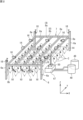
図1は、実施形態に係る農作業システムの全体構成の一例を示す図である。
図1中、農作業システム1は、圃場Fの上方に設置された太陽光発電機構100を備える。農作業システム1は、太陽光発電機構100により、圃場Fで作物の栽培をしつつ太陽光発電を行うことが可能である。
圃場Fで栽培されている作物Cは、例えば、ブドウである。
図1は、実施形態に係る農作業システムの全体構成の一例を示す図である。
図1中、農作業システム1は、圃場Fの上方に設置された太陽光発電機構100を備える。農作業システム1は、太陽光発電機構100により、圃場Fで作物の栽培をしつつ太陽光発電を行うことが可能である。
圃場Fで栽培されている作物Cは、例えば、ブドウである。
圃場Fには、作物Cを収穫することで得られる収穫物を貯蔵するタンク47が設置されている。タンク47には、搾りかす貯蔵タンク48と、果汁貯蔵タンク49と、が接続されている。タンク47は、収穫物である果実を圧搾し果汁と搾りかすとに分離する機能を有する。また、タンク47は、除梗破砕機および選果機の機能を有する場合がある。この場合、収穫物は、除梗破砕機によって果梗と果実とに分離され、その後果実のみが圧搾される。
タンク47によって分離された果汁および搾りかすは搾りかす貯蔵タンク48および果汁貯蔵タンク49へ送られる。なお、搾りかす貯蔵タンク48および果汁貯蔵タンク49は、貯蔵物を冷却する機能を備えていてもよい。
タンク47は、圃場Fの縁部に設置されている。また、搾りかす貯蔵タンク48および果汁貯蔵タンク49は、圃場Fの外部に設置されている。
タンク47によって分離された果汁および搾りかすは搾りかす貯蔵タンク48および果汁貯蔵タンク49へ送られる。なお、搾りかす貯蔵タンク48および果汁貯蔵タンク49は、貯蔵物を冷却する機能を備えていてもよい。
タンク47は、圃場Fの縁部に設置されている。また、搾りかす貯蔵タンク48および果汁貯蔵タンク49は、圃場Fの外部に設置されている。
農作業システム1は、圃場Fにおける作物Cの状態を制御(管理)する機能、および、圃場Fにおける農作業を支援する機能を有する。
なお、以下の説明では、各図中、互いに直交する3方向をX方向、Y方向、及びZ方向とする。Z方向は、鉛直方向である。
なお、以下の説明では、各図中、互いに直交する3方向をX方向、Y方向、及びZ方向とする。Z方向は、鉛直方向である。
農作業システム1は、太陽光発電機構100の他、制御装置4と、架台6と、レールユニット7と、複数の作業ユニット10と、複数のコンテナ装置50と、を備える。
太陽光発電機構100は、複数の太陽光発電パネル2と、複数の仰角可変機構と、を含む。複数の太陽光発電パネル2はそれぞれ、複数のセル2aと、パネルフレーム2bと、を備える。複数のセル2aは、パネルフレーム2b上に配列されている。パネルフレーム2bは、複数のセル2aをパネル状に保持する。
太陽光発電機構100は、複数の太陽光発電パネル2と、複数の仰角可変機構と、を含む。複数の太陽光発電パネル2はそれぞれ、複数のセル2aと、パネルフレーム2bと、を備える。複数のセル2aは、パネルフレーム2b上に配列されている。パネルフレーム2bは、複数のセル2aをパネル状に保持する。
複数の太陽光発電パネル2が出力する電力は、DC/DCコンバータ等を介して電圧が調整され、パワーコンディショナ(PCS)12へ与えられる。PCS12は、複数の太陽光発電パネル2からの電力を交流に変換し、PCS12に接続される負荷へ電力を供給する。また、PCS12は、商用交流電源系統に連系しており、複数の太陽光発電パネル2からの電力を系統へ与えることもある。
また、本システム1の各部は、PCS12に負荷として接続される。よって、複数の太陽光発電パネル2の電力は、本システム1の各部に供給される。
つまり、PCS12は、太陽光発電パネル2が発電した電力を、作業ユニット10(農作業装置または移動機構)に対して供給する電力供給装置として機能する。
この場合、太陽光発電パネル2による電力を有効活用することができる。
また、本システム1の各部は、PCS12に負荷として接続される。よって、複数の太陽光発電パネル2の電力は、本システム1の各部に供給される。
つまり、PCS12は、太陽光発電パネル2が発電した電力を、作業ユニット10(農作業装置または移動機構)に対して供給する電力供給装置として機能する。
この場合、太陽光発電パネル2による電力を有効活用することができる。
なお、農作業システム1は、前記DC/DCコンバータの出力を蓄電するための蓄電池を備えていてもよい。この蓄電池に蓄電される直流電力は、後述する充電ステーションにおいて出力される電力や、本システム1において必要となる直流電力として利用される。
架台6は、複数の太陽光発電パネル2を支持する。架台6は、複数の支柱6aと、複数の梁フレーム6bと、複数の支持フレーム6cと、を備える。複数の支柱6a、複数の梁フレーム6b、および、複数の支持フレーム6cは、鋼材やアルミニウム合金材等からなる棒状の部材である。
複数(図例では4本)の支柱6aは、圃場Fの縁部にZ方向に沿って立設される。なお、図1では、支柱6aは、圃場Fの四隅に設けられている。
複数(図例では5本)の梁フレーム6bは、圃場Fの上方に設けられる。複数の梁フレーム6bは、Y方向に沿って延びている。複数の梁フレーム6bは、一定の間隔を置いてX方向に並べて配置されている。
複数の梁フレーム6bの上部には、それぞれ、上述の複数の仰角可変機構が設けられている。複数の仰角可変機構は、梁フレーム6b上で太陽光発電パネル2の仰角を変更可能に太陽光発電パネル2を支持する。
複数(図例では4本)の支柱6aは、圃場Fの縁部にZ方向に沿って立設される。なお、図1では、支柱6aは、圃場Fの四隅に設けられている。
複数(図例では5本)の梁フレーム6bは、圃場Fの上方に設けられる。複数の梁フレーム6bは、Y方向に沿って延びている。複数の梁フレーム6bは、一定の間隔を置いてX方向に並べて配置されている。
複数の梁フレーム6bの上部には、それぞれ、上述の複数の仰角可変機構が設けられている。複数の仰角可変機構は、梁フレーム6b上で太陽光発電パネル2の仰角を変更可能に太陽光発電パネル2を支持する。
複数(図例では2本)の支持フレーム6cは、X方向に沿って延びている。複数の支持フレーム6cは、複数の梁フレーム6bの先端同士および支柱6aの先端を連結する。これにより、複数の梁フレーム6bおよび複数の太陽光発電パネル2は、圃場Fの上方で支持される。
図2は、レールユニット7を示す図である。図2では、太陽光発電機構100、架台6の梁フレーム6b、および支持フレーム6cを除いた状態の架台6を示している。
レールユニット7は、複数の作業ユニット10およびコンテナ装置50が走行する軌道を構成する。レールユニット7は、複数の太陽光発電パネル2と、圃場Fの地面との間に設けられている。
レールユニット7は、複数のレール8によって構成される。複数のレール8は、例えば、C型鋼からなる棒状の部材である。複数のレール8は、複数の第1レール8aと、複数の第2レール8bと、を含む。
レールユニット7は、複数の作業ユニット10およびコンテナ装置50が走行する軌道を構成する。レールユニット7は、複数の太陽光発電パネル2と、圃場Fの地面との間に設けられている。
レールユニット7は、複数のレール8によって構成される。複数のレール8は、例えば、C型鋼からなる棒状の部材である。複数のレール8は、複数の第1レール8aと、複数の第2レール8bと、を含む。
複数(図例では5本)の第1レール8aは、Y方向に沿って延びている。複数の第1レール8aは、一定の間隔をおいてX方向に並べて配置されている。
複数(図例では2本)の第2レール8bは、X方向に沿って延びている。複数の第2レール8bは、複数の第1レール8aの先端同士を連結する。これによりレールユニット7は、格子状に構成される。言い換えると、レールユニット7は、複数のレール8を含むレール網である。
複数(図例では2本)の第2レール8bは、X方向に沿って延びている。複数の第2レール8bは、複数の第1レール8aの先端同士を連結する。これによりレールユニット7は、格子状に構成される。言い換えると、レールユニット7は、複数のレール8を含むレール網である。
レールユニット7には、複数の環境検出部14が設けられている。複数の環境検出部14は、圃場F全体に亘って所定の間隔をおいて設けられる。複数の環境検出部14は、例えば、温湿度センサと、風量センサと、を含む。環境検出部14は、圃場Fの環境として、温度、湿度、および風量を検出する。環境検出部14は、制御装置4に通信可能に接続されている。環境検出部14の出力は、制御装置4へ与えられる。
また、レールユニット7には、複数のカメラ16が設けられている。複数のカメラ16は、圃場F全体に亘って所定の間隔をおいて設けられる。複数のカメラ16は、圃場Fの作物Cを撮像する。複数のカメラ16は、制御装置4に通信可能に接続されている。複数のカメラ16が出力する画像データは、制御装置4へ与えられる。
また、架台6には、複数の無線通信機18が設けられている。複数の無線通信機18は、圃場F全体に亘って所定の間隔をおいて設けられる。複数の無線通信機18は、作業ユニット10およびコンテナ装置50との間で無線通信を行う機能を有する。複数の無線通信機18は、制御装置4に接続されている。制御装置4は、複数の無線通信機18を介して作業ユニット10およびコンテナ装置50と通信することができる。
複数の無線通信機18は、作業ユニット10およびコンテナ装置50との間で、例えば、無線LANによる通信を行う。つまり、複数の無線通信機18は、アクセスポイントである。以下の説明では、複数の無線通信機18をアクセスポイント18と呼ぶことがある。
なお、図2は、アクセスポイント18が4つの支柱6aのそれぞれに設けられている場合を示している。アクセスポイント18は、架台6に設けてもよいし、レールユニット7に設けてもよい。
複数の無線通信機18は、作業ユニット10およびコンテナ装置50との間で、例えば、無線LANによる通信を行う。つまり、複数の無線通信機18は、アクセスポイントである。以下の説明では、複数の無線通信機18をアクセスポイント18と呼ぶことがある。
なお、図2は、アクセスポイント18が4つの支柱6aのそれぞれに設けられている場合を示している。アクセスポイント18は、架台6に設けてもよいし、レールユニット7に設けてもよい。
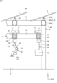
図3は、作業ユニット10、コンテナ装置50、および、太陽光発電機構100を含む架台6の一部を示す図である。
太陽光発電パネル2および仰角可変機構20は、上述したように、架台6の梁フレーム6bに設けられている。梁フレーム6bには、仰角可変機構20が設けられている。仰角可変機構20は、台座20aと、支持部20bと、アクチュエータ20cと、を備える。台座20aは、梁フレーム6bの上面に設けられる。支持部20bは、台座20aに対して回動可能に設けられる。支持部20bは、Y方向に沿う軸回りに回動する。支持部20bは、太陽光発電パネル2の下面に固定される。よって、太陽光発電パネル2は、支持部20bとともに台座20aに対して回動可能である。これにより、仰角可変機構20は、太陽光発電パネル2の仰角を変更可能に太陽光発電パネル2を支持する。アクチュエータ20cは、支持部20bの回動を駆動する。つまり、太陽光発電パネル2の仰角は、アクチュエータ20cを制御することで変更することができる。
アクチュエータ20cは、制御装置4によって制御される。
本実施形態では、仰角可変機構20によって太陽光発電パネル2の仰角を変更することで、圃場Fの日射量や、圃場Fの風量を調整することができる。
つまり、仰角可変機構20は、圃場Fの日射量を調整する調整機構を構成する。
太陽光発電パネル2および仰角可変機構20は、上述したように、架台6の梁フレーム6bに設けられている。梁フレーム6bには、仰角可変機構20が設けられている。仰角可変機構20は、台座20aと、支持部20bと、アクチュエータ20cと、を備える。台座20aは、梁フレーム6bの上面に設けられる。支持部20bは、台座20aに対して回動可能に設けられる。支持部20bは、Y方向に沿う軸回りに回動する。支持部20bは、太陽光発電パネル2の下面に固定される。よって、太陽光発電パネル2は、支持部20bとともに台座20aに対して回動可能である。これにより、仰角可変機構20は、太陽光発電パネル2の仰角を変更可能に太陽光発電パネル2を支持する。アクチュエータ20cは、支持部20bの回動を駆動する。つまり、太陽光発電パネル2の仰角は、アクチュエータ20cを制御することで変更することができる。
アクチュエータ20cは、制御装置4によって制御される。
本実施形態では、仰角可変機構20によって太陽光発電パネル2の仰角を変更することで、圃場Fの日射量や、圃場Fの風量を調整することができる。
つまり、仰角可変機構20は、圃場Fの日射量を調整する調整機構を構成する。
複数の作業ユニット10は、レールユニット7に懸下されている。複数の作業ユニット10は、レールユニット7のレール8に沿って移動し、圃場Fの作物Cに対する農作業を実行したり、作物Cの状態を検出したりする機能を有する。
複数のコンテナ装置50も、作業ユニット10と同様、レールユニット7に懸下されている。複数のコンテナ装置50は、収穫物である果実を積載する機能、およびレール8に沿って移動することで積載された果実を搬送する機能を有する。
〔作業ユニット10およびコンテナ装置50について〕
図3中、複数の作業ユニット10は、それぞれ、農作業装置22と、移動機構24と、コントロールボックス26と、を備える。
農作業装置22は、作物Cに対して行われる農作業を実行する機能や、作物Cの状態を検出するセンサとしての機能を有する。
移動機構24は、農作業装置22をレール8に沿って移動させる機能を有する。
図3中、複数の作業ユニット10は、それぞれ、農作業装置22と、移動機構24と、コントロールボックス26と、を備える。
農作業装置22は、作物Cに対して行われる農作業を実行する機能や、作物Cの状態を検出するセンサとしての機能を有する。
移動機構24は、農作業装置22をレール8に沿って移動させる機能を有する。
農作業装置22は、アーム30と、エンドエフェクタ32と、を備える。
アーム30の上端は、移動機構24に固定されている。アーム30は、移動機構24から下方向へ延びている。エンドエフェクタ32は、アーム30の下端に設けられている。
アーム30の上端は、移動機構24に固定されている。アーム30は、移動機構24から下方向へ延びている。エンドエフェクタ32は、アーム30の下端に設けられている。
アーム30は、移動機構24の周囲の所定範囲内においてエンドエフェクタ32の位置を変更可能なマニピュレータである。アーム30は、複数の関節30aを含む多関節のマニピュレータである。
エンドエフェクタ32は、作物Cに対する農作業等の作業動作が可能なデバイスである。エンドエフェクタ32は、アーム30によって作業位置に配置される。エンドエフェクタ32は、作業位置において、作業動作を行う。
エンドエフェクタ32は、アーム30に対して着脱自在に設けられている。
本実施形態において、エンドエフェクタ32は、作業動作ごとに複数種類用意されている。よって、農作業装置22は、エンドエフェクタ32を交換することで、複数種類の作業動作を行うことができる。
エンドエフェクタ32は、アーム30に対して着脱自在に設けられている。
本実施形態において、エンドエフェクタ32は、作業動作ごとに複数種類用意されている。よって、農作業装置22は、エンドエフェクタ32を交換することで、複数種類の作業動作を行うことができる。
エンドエフェクタ32は、収穫作業用のエンドエフェクタ32、剪定用のエンドエフェクタ32、放水用のエンドエフェクタ32、施肥用のエンドエフェクタ32、農薬散布用のエンドエフェクタ32、作物Cの状態検出用のエンドエフェクタ32、および撮像用のエンドエフェクタ32を含む。
図3中、エンドエフェクタ32aは、収穫用である。収穫用のエンドエフェクタ32aは、作物Cの果実を把持し果実の収穫作業を実行することができる。
農作業装置22は、収穫した果実を、コンテナ装置50へ積載する。
農作業装置22は、収穫した果実を、コンテナ装置50へ積載する。
コンテナ装置50は、農作業装置22や圃場の作業者が収穫した果実を搬送する。コンテナ装置50が搬送する果実は、農作業装置22および作業者によって積載される。
コンテナ装置50は、それぞれ、コンテナ52と、移動機構54と、コントロールボックス56と、連結シャフト58と、を備える。
コンテナ52は、果実(収穫物)が積載される容器である。
移動機構54は、コンテナ52をレール8に沿って移動させる機能を有している。移動機構54は、移動機構24と同様の構成を有する。
連結シャフト58は、移動機構54と、コンテナ52と、を連結している。
コントロールボックス56は、連結シャフト58に固定されている。コントロールボックス56は、コンテナ装置50の各部を制御する制御装置や、蓄電池、無線通信装置等を内部に収容する。
コンテナ装置50は、それぞれ、コンテナ52と、移動機構54と、コントロールボックス56と、連結シャフト58と、を備える。
コンテナ52は、果実(収穫物)が積載される容器である。
移動機構54は、コンテナ52をレール8に沿って移動させる機能を有している。移動機構54は、移動機構24と同様の構成を有する。
連結シャフト58は、移動機構54と、コンテナ52と、を連結している。
コントロールボックス56は、連結シャフト58に固定されている。コントロールボックス56は、コンテナ装置50の各部を制御する制御装置や、蓄電池、無線通信装置等を内部に収容する。
図4は、移動機構54を示す図である。図4では、長手方向に沿う方向からレール8をみたときの移動機構54を示している。よって、レール8は、レール8の長手方向に直交する平面に沿った断面図として示されている。なお、移動機構24も移動機構54と同様の構成を有する。よって、ここでは、移動機構54のみを説明する。
レール8は、上述したように、C型鋼である。よって、レール8の底板8rは、長手方向に沿うスリット8sを有する。レール8の底板8rは、レール8の下面を構成する部材である。スリット8sは、レール8の内外を連通する。スリット8sは、下向きに開口する。
移動機構54は、レール8の内部空間8kを走行する。
移動機構54は、本体部40と、一対の車輪42と、一対のモータ44と、を備えている。
一対のモータ44は、本体部40の両端に設けられている。一対のモータ44の回転軸は互いに同心に設けられている。一対のモータ44は、いわゆるインホイールモータである。よって、一対のモータ44のロータ(図示省略)の外周面に一対の車輪42が一体に設けられている。一対のモータ44は、一対の車輪42の車軸を構成しつつ、一対の車輪42を回転駆動する。
移動機構54は、本体部40と、一対の車輪42と、一対のモータ44と、を備えている。
一対のモータ44は、本体部40の両端に設けられている。一対のモータ44の回転軸は互いに同心に設けられている。一対のモータ44は、いわゆるインホイールモータである。よって、一対のモータ44のロータ(図示省略)の外周面に一対の車輪42が一体に設けられている。一対のモータ44は、一対の車輪42の車軸を構成しつつ、一対の車輪42を回転駆動する。
本体部40は、一対のモータ44の間に介在し、一対のモータ44を一体に連結している。本体部40には、連結シャフト58が固定されている。連結シャフト58は、本体部40から下方向に延びており、スリット8sを通過してレール8の底板8rから突出している。連結シャフト58の下端は、コンテナ52に接続されている。
コントロールボックス56は、レール8の下側に配置されている。
なお、一対のモータ44は、互いに独立して制御される。よって、一対のモータ44は、同じ方向に回転したり、互いに逆方向に回転したりすることがある。
コントロールボックス56は、レール8の下側に配置されている。
なお、一対のモータ44は、互いに独立して制御される。よって、一対のモータ44は、同じ方向に回転したり、互いに逆方向に回転したりすることがある。
レール8の底板8rがスリット8sを有するので、連結シャフト58はレール8の底板8rから突出する。また、一対の車輪42は、底板8rに接触している。これにより、コンテナ装置50は、レール8に懸下される。また、一対のモータ44によって一対の車輪42が回転駆動されると、コンテナ装置50は、底板8r上を走行する。これにより、コンテナ装置50は、レールユニット7のレール8に沿って移動することができる。
コンテナ装置50は、レール8に含まれる第1レール8aおよび第2レール8bを移動することができる。よって、コンテナ装置50は、レールユニット7の全域に亘って移動することができる。
コンテナ装置50は、レール8に含まれる第1レール8aおよび第2レール8bを移動することができる。よって、コンテナ装置50は、レールユニット7の全域に亘って移動することができる。
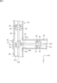
図5は、第1レール8aと、第2レール8bと、の連結部分を通過する際の移動機構54の動きを説明するための図である。図5では、上方からレール8をみたときの移動機構54を示している。よって、レール8は、X-Y平面に沿った断面図として示されている。
図5では、移動機構54が、位置P1から位置P2を経由して位置P3へ移動するときの状態を示している。位置P1は、第1レール8a上の位置である。位置P1では、移動機構54は、第1レール8aを第2レール8b側へ向かって走行している。よって、このとき、移動機構54の一対のモータ44は、同じ方向に回転する。
第1レール8aの端部8a1は、第2レール8bの開口部8b1に接続されている。開口部8b1は、端部8a1に対応して設けられている。第1レール8aの底板8r1と、第2レール8bの底板8r2と、は開口部8b1において接続されている。
よって、第1レール8aを走行する移動機構54は、開口部8b1を通過して、第2レール8bの内部空間へ進入することができる。
よって、第1レール8aを走行する移動機構54は、開口部8b1を通過して、第2レール8bの内部空間へ進入することができる。
第2レール8bの底板8r2には、スリット8s2の他、連結スリット8s3が設けられている。連結スリット8s3は、第2レール8bのスリット8a2に直角に繋がっている。連結スリット8s3は、第2レール8bのスリット8a2と、第1レール8aのスリット8s1と、を繋ぐ。
開口部8b1を通過して第2レール8bの内部空間へ進入すると、移動機構54は、連結スリット8s3に沿って第2レール8bの内部を走行し、スリット8s2と連結スリット8s3とが繋がる地点に到達する。
位置P2は、スリット8s2と連結スリット8s3とが繋がる地点である。
移動機構54が位置P2に到達すると、一対のモータ44が互いに逆方向に回転するように制御される。これにより、移動機構54は、位置P2に位置したままその場で回転する。つまり、移動機構54は位置P2に位置した状態で方向転換する。一対のモータ44の回転軸がY方向にほぼ平行になると、移動機構54は方向転換を終え、第2レール8bのスリット8s2に沿って走行を開始し、位置P3へ進行する。
以上のようにして、移動機構54は、第1レール8aと、第2レール8bと、の連結部分を通過する。
位置P2は、スリット8s2と連結スリット8s3とが繋がる地点である。
移動機構54が位置P2に到達すると、一対のモータ44が互いに逆方向に回転するように制御される。これにより、移動機構54は、位置P2に位置したままその場で回転する。つまり、移動機構54は位置P2に位置した状態で方向転換する。一対のモータ44の回転軸がY方向にほぼ平行になると、移動機構54は方向転換を終え、第2レール8bのスリット8s2に沿って走行を開始し、位置P3へ進行する。
以上のようにして、移動機構54は、第1レール8aと、第2レール8bと、の連結部分を通過する。
このように、移動機構54(コンテナ装置50)は、第1レール8aと、第2レール8bと、の間を移動することができ、レールユニット7の全域に亘って移動することができる。
なお、第2レール8bにおいて、開口部8b1に対向する部分には、逃げ部8cが設けられている。逃げ部8cは、第2レール8bの内面8dに対して外方へ凹む部分である。逃げ部8cは、位置P2で方向転換する移動機構54が第2レール8bの内面8dに接触するのを防止するために設けられている。
なお、第2レール8bにおいて、開口部8b1に対向する部分には、逃げ部8cが設けられている。逃げ部8cは、第2レール8bの内面8dに対して外方へ凹む部分である。逃げ部8cは、位置P2で方向転換する移動機構54が第2レール8bの内面8dに接触するのを防止するために設けられている。
このように、本実施形態では、太陽光発電パネル2を支持する架台6にレールユニット7を設けたことで、圃場F全体を移動可能なコンテナ装置50や作業ユニット10を容易に設置することができる。
この結果、圃場Fの管理作業や農作業の効率化を図ることが可能となる。
また、本実施形態では、レールユニット7が架台6に支持されているので、架台6以外に別途レールユニット7を指示するための支柱を設けることなく、レールユニット7を設置することができる。
この結果、圃場Fの管理作業や農作業の効率化を図ることが可能となる。
また、本実施形態では、レールユニット7が架台6に支持されているので、架台6以外に別途レールユニット7を指示するための支柱を設けることなく、レールユニット7を設置することができる。
図6は、コンテナ装置50の要部を示す図である。図6では、コンテナ52を断面図として示している。
また、図6では、コンテナ装置50がタンク47の上方に位置する場合を例示している。
コンテナ装置50は、果実が積載される積載位置から所定の停止位置へ移動する。本実施形態では、停止位置は、レールユニット7上の位置のうち、タンク47が設置されている位置に対応する位置である。
タンク47は、図1および図2に示すように、圃場Fの縁部に設置されている。よって、停止位置は、レールユニット7の縁部に位置する第1レール8a上の位置である。
図6では、コンテナ装置50が停止位置に位置している場合を示している。
また、図6では、コンテナ装置50がタンク47の上方に位置する場合を例示している。
コンテナ装置50は、果実が積載される積載位置から所定の停止位置へ移動する。本実施形態では、停止位置は、レールユニット7上の位置のうち、タンク47が設置されている位置に対応する位置である。
タンク47は、図1および図2に示すように、圃場Fの縁部に設置されている。よって、停止位置は、レールユニット7の縁部に位置する第1レール8a上の位置である。
図6では、コンテナ装置50が停止位置に位置している場合を示している。
図6に示すように、コンテナ52は、鋼板またはアルミニウム合金材等によって形成された、上面に開口を有する矩形箱状の容器である。コンテナ52は、側壁部52aと、底部52bと、梁部52cと、を備える。
側壁部52aは、コンテナ52の側面を構成する矩形筒状の部材である。側壁部52aは、4つの側板52a1を含む。果実は、側壁部52aの上側の開口から投入され、コンテナ52内に積載される。
側壁部52aは、コンテナ52の側面を構成する矩形筒状の部材である。側壁部52aは、4つの側板52a1を含む。果実は、側壁部52aの上側の開口から投入され、コンテナ52内に積載される。
梁部52cは、4つの側板52a1のうち互いに対向する一対の側板52a1を連結している。梁部52cには、連結シャフト58が接続されている。連結シャフト58は、コンテナ52の梁部52cと、移動機構54と、を連結している。
底部52bは、コンテナ52の底面を構成する板状の部材である。底部52bは、側壁部52aの下側の開口を塞いでいる。
底部52bは、一対の底板52b1を備える。一対の底板52b1は、梁部52cに並行な一対の側板52a1に設けられている。
一対の底板52b1の端縁と、一対の側板52a1の端縁とは、ヒンジ57を介して連結されている。これにより、一対の底板52b1は、図6中の2点鎖線で示すように、ヒンジ57を中心に開閉可能である。
一対の底板52b1が閉鎖状態のとき、一対の底板52b1の先端部は、梁部52cに当接する。
底部52bは、一対の底板52b1を備える。一対の底板52b1は、梁部52cに並行な一対の側板52a1に設けられている。
一対の底板52b1の端縁と、一対の側板52a1の端縁とは、ヒンジ57を介して連結されている。これにより、一対の底板52b1は、図6中の2点鎖線で示すように、ヒンジ57を中心に開閉可能である。
一対の底板52b1が閉鎖状態のとき、一対の底板52b1の先端部は、梁部52cに当接する。
底部52bが開閉されることで、コンテナ52内に積載される果実は、下方向へ移送可能である。
コンテナ装置50は、果実を下方向へ移送させる移送機構60を備える。移送機構60は、ロック装置60aと、閉鎖装置60bと、を備える。
ロック装置60aは、梁部52cに設けられている。ロック装置60aは、閉鎖状態の一対の底板52b1の先端部を保持または解除する。ロック装置60aが保持状態である場合、底部52bは閉鎖状態であり、コンテナ52内には、果実が積載される。ロック装置60aが保持状態から解除状態へ切り替わると、底部52bは果実の自重によって閉鎖状態から開放状態となり、果実は下方向へ落下する。
このように、移送機構60のロック装置60aは、コンテナ52の底部52bを開放することでコンテナ52内の果実を下方向へ移送する。
コンテナ装置50は、果実を下方向へ移送させる移送機構60を備える。移送機構60は、ロック装置60aと、閉鎖装置60bと、を備える。
ロック装置60aは、梁部52cに設けられている。ロック装置60aは、閉鎖状態の一対の底板52b1の先端部を保持または解除する。ロック装置60aが保持状態である場合、底部52bは閉鎖状態であり、コンテナ52内には、果実が積載される。ロック装置60aが保持状態から解除状態へ切り替わると、底部52bは果実の自重によって閉鎖状態から開放状態となり、果実は下方向へ落下する。
このように、移送機構60のロック装置60aは、コンテナ52の底部52bを開放することでコンテナ52内の果実を下方向へ移送する。
閉鎖装置60bは、開放状態の底部52bを閉鎖状態に回動させる機能を有する。閉鎖装置60bは、底部52b(一対の底板52b1)を回動させるためのリンク機構やアクチュエータ等を含む。閉鎖装置60bは、コンテナ52内の果実を下方向へ移送した後、底部52bを閉鎖状態にする。その後、ロック装置60aは、保持状態となる。これにより、コンテナ52内は空状態となり、再度、果実の積載が可能となる。
図6に示すように、タンク47は、果実を受け取るための受取口47aを有する。受取口47aは、タンク47の上面に設けられる。よって、受取口47aは、上方向から落下してくる果実を受け取ることができる。
図6に示すように、コンテナ装置50が停止位置に位置するとき、ロック装置60aが保持状態から解除状態へ切り替えられると、コンテナ52内の果実は下方向へ落下する。
落下した果実は、タンク47の受取口47aによって受け取られる。
このように、本実施形態では、コンテナ装置50が、果実を下方向へ落下させる移送機構60を備え、タンク47が、受取口47aを備えるので、停止位置のコンテナ装置50に積載された果実(収穫物)をタンク47へ移送することができる。
落下した果実は、タンク47の受取口47aによって受け取られる。
このように、本実施形態では、コンテナ装置50が、果実を下方向へ落下させる移送機構60を備え、タンク47が、受取口47aを備えるので、停止位置のコンテナ装置50に積載された果実(収穫物)をタンク47へ移送することができる。
上記構成によれば、レール8に吊り下げられたコンテナ装置50が、レールユニット7の縁部の停止位置までレール8に沿って移動可能であるので、圃場Fにトラクタ等の車両を走行させるスペースを確保することなく、果実を圃場Fの外縁まで搬送することができる。
この結果、適切に果実を搬送することができる。
このように、農作業システム1は、レールユニット7と、コンテナ装置50と、を備えることで、収穫物の搬送システムを構成する。
この結果、適切に果実を搬送することができる。
このように、農作業システム1は、レールユニット7と、コンテナ装置50と、を備えることで、収穫物の搬送システムを構成する。
また、図6に示すように、コンテナ装置50は、測定部62と、検出部64と、を備える。
測定部62は、コンテナ52内に積載される果実の積載量を測定する機能を有する。測定部62は、例えば、コンテナ52全体の重量を測定する。コンテナ52全体の重力を測定することで、コンテナ52内に積載される果実の重量を積載量として測定する。
なお、測定部62によって測定される積載量は、コンテナ52内において果実が占める体積であってもよい。
検出部64は、コンテナ52内に積載される果実の状態を検出する機能を有する。検出部64が検出する状態には、例えば、果実の糖度や、酸度、水分量が含まれる。
測定部62は、コンテナ52内に積載される果実の積載量を測定する機能を有する。測定部62は、例えば、コンテナ52全体の重量を測定する。コンテナ52全体の重力を測定することで、コンテナ52内に積載される果実の重量を積載量として測定する。
なお、測定部62によって測定される積載量は、コンテナ52内において果実が占める体積であってもよい。
検出部64は、コンテナ52内に積載される果実の状態を検出する機能を有する。検出部64が検出する状態には、例えば、果実の糖度や、酸度、水分量が含まれる。
〔制御装置4およびコンテナ装置50の機能的構成について〕
図7は、制御装置4およびコンテナ装置50の機能的構成の一例を示すブロック図である。
制御装置4は、パーソナルコンピュータや、サーバ等のコンピュータである。制御装置4は、スマートフォンや、タブレット等でもよいし、クラウド上のコンピュータシステムであってもよい。
図7は、制御装置4およびコンテナ装置50の機能的構成の一例を示すブロック図である。
制御装置4は、パーソナルコンピュータや、サーバ等のコンピュータである。制御装置4は、スマートフォンや、タブレット等でもよいし、クラウド上のコンピュータシステムであってもよい。
制御装置4には、複数のアクセスポイント18、複数の環境検出部14、複数のカメラ16、および、複数のアクチュエータ20cが接続されている。
制御装置4と、これらデバイスと、は、互いに有線または無線によって通信接続される。制御装置4は、これらデバイスへ制御命令を与えて制御することができる。また、制御装置4は、これらデバイスから与えられる出力を受け付けることができる。
制御装置4は、ネットワークを介して種々の情報サーバに通信可能に接続されている。前記ネットワークは、ローカルネットワークでもよいし、グローバルネットでもよい。さらにネットワークは、ローカルネットワークとグローバルネットとを組み合わせて構成されたものであってもよい。
制御装置4と、これらデバイスと、は、互いに有線または無線によって通信接続される。制御装置4は、これらデバイスへ制御命令を与えて制御することができる。また、制御装置4は、これらデバイスから与えられる出力を受け付けることができる。
制御装置4は、ネットワークを介して種々の情報サーバに通信可能に接続されている。前記ネットワークは、ローカルネットワークでもよいし、グローバルネットでもよい。さらにネットワークは、ローカルネットワークとグローバルネットとを組み合わせて構成されたものであってもよい。
制御装置4は、処理部4aと、記憶部4bと、入出力部4cと、を備える。
処理部4aは、例えば、CPU(Central Processing Unit)、GPU(Graphics Processing Unit)、DSP(Digital Signal Processor)、FPGA(Field Programmable Gate Array)等、コンピュータの制御に適合する種々のプロセッサである。
処理部4aは、例えば、CPU(Central Processing Unit)、GPU(Graphics Processing Unit)、DSP(Digital Signal Processor)、FPGA(Field Programmable Gate Array)等、コンピュータの制御に適合する種々のプロセッサである。
記憶部4bは、例えば、フラッシュメモリ、ハードディスク、ROM(Read Only Memory)、RAM(Random Access Memory)等である。
記憶部4bには、処理部4aに実行させるためのコンピュータプログラムや、必要な情報が記憶されている。処理部4aは、記憶部4bのようなコンピュータ読み取り可能な非一過性の記録媒体に記憶されたコンピュータプログラムを実行することで、処理部4aが有する各種処理機能を実現する。
処理部4aは、環境検出部14や、カメラ16、作業ユニット10(農作業装置22)、コンテナ装置50等を制御し、圃場Fの作物Cの品質制御を行ったり、作業ユニット10に農作業を行わせたり、コンテナ装置50に果実の搬送作業を行わせたりする機能を有する。
記憶部4bには、処理部4aに実行させるためのコンピュータプログラムや、必要な情報が記憶されている。処理部4aは、記憶部4bのようなコンピュータ読み取り可能な非一過性の記録媒体に記憶されたコンピュータプログラムを実行することで、処理部4aが有する各種処理機能を実現する。
処理部4aは、環境検出部14や、カメラ16、作業ユニット10(農作業装置22)、コンテナ装置50等を制御し、圃場Fの作物Cの品質制御を行ったり、作業ユニット10に農作業を行わせたり、コンテナ装置50に果実の搬送作業を行わせたりする機能を有する。
また、処理部4aは、複数の作業ユニット10の位置および複数のコンテナ装置50の位置を検出する処理を実行する機能を有する。処理部4aは、複数のアクセスポイント18を介して作業ユニット10およびコンテナ装置50と無線LAN通信を行う。処理部4aは、作業ユニット10およびコンテナ装置50からの信号を受信したときの受信信号に関する情報を複数のアクセスポイント18から取得する。処理部4aは、複数のアクセスポイント18から取得した受信信号に関する情報に基づいて、作業ユニット10の位置およびコンテナ装置50の位置を検出する。受信信号に関する情報には、RSSI(Received Signal Strength Indicator)や、CSI(Channel State Information)が含まれる。
複数のアクセスポイント18は、圃場F全体に亘って所定の間隔をおいて設けられている。つまり、複数のアクセスポイント18の位置は既知である。このため、複数のアクセスポイント18における受信信号に関する情報を解析することで、信号源である作業ユニット10の位置およびコンテナ装置50の位置を検出することができる。処理部4aは、複数の作業ユニット10それぞれの位置を検出する。検出された作業ユニット10の位置およびコンテナ装置50の位置は、作業ユニット10およびコンテナ装置50の制御に用いられる。また、作業ユニット10の位置およびコンテナ装置50の位置は、作業ユニット10およびコンテナ装置50へ与えられることがある。
本実施形態では、作業ユニット10の上方には太陽光発電パネル2が設けられているため、GPS受信機を用いた位置検出が困難な場合がある。
これに対して、本実施形態では、複数のアクセスポイント18を用いて作業ユニット10の位置検出およびコンテナ装置50の位置検出を行うので、上方に太陽光発電パネル2が設けられていても、作業ユニット10の位置およびコンテナ装置50の位置を精度よく検出することができる。
これに対して、本実施形態では、複数のアクセスポイント18を用いて作業ユニット10の位置検出およびコンテナ装置50の位置検出を行うので、上方に太陽光発電パネル2が設けられていても、作業ユニット10の位置およびコンテナ装置50の位置を精度よく検出することができる。
なお、作業ユニット10およびコンテナ装置50の位置検出は、レーザ光を用いた距離測定によって行ってもよいし、ステレオカメラを用いた距離測定によって行ってもよい。これら距離測定による位置検出では、作業ユニット10(コンテナ装置50)と基準位置との距離を測定することで、作業ユニット10(コンテナ装置50)の位置検出が行われる。
また、処理部4aは、複数のカメラ16による画像データに基づいて、圃場Fで作業する作業者の位置を検出することもできる。
入出力部4cは、制御装置4のオペレータによる入力を受け付ける機能を有するとともに、各種情報を出力する機能を有する。入出力部4cは、例えば、キーボードや、マウス、タッチパネルといった入力デバイスや、モニタや、スピーカ、プリンタといった出力デバイスを含む。
コンテナ装置50は、上述の移動機構54や、移送機構60、測定部62、検出部64の他、制御装置46と、蓄電池45と、無線通信機43と、を備える。
制御装置46、蓄電池45、および無線通信機43は、コントロールボックス56内に収容される。制御装置46は、移動機構54や、移送機構60を制御する機能を有する。
制御装置46、蓄電池45、および無線通信機43は、コントロールボックス56内に収容される。制御装置46は、移動機構54や、移送機構60を制御する機能を有する。
蓄電池45は、コンテナ装置50の各部へ電力を供給する。
無線通信機43は、制御装置4との間の無線通信に用いられる。無線通信機43は、複数のアクセスポイント18との間で無線LAN通信を行う機能を有する。
無線通信機43は、制御装置4との間の無線通信に用いられる。無線通信機43は、複数のアクセスポイント18との間で無線LAN通信を行う機能を有する。
制御装置46は、コンピュータである。制御装置46には、移動機構54、移送機構60、測定部62、検出部64、および無線通信機43が接続されている。
制御装置46は、これらデバイスへ制御命令を与えて制御することができる。また、制御装置46は、これらデバイスから与えられる出力を受け付けることができる。
制御装置46は、これらデバイスへ制御命令を与えて制御することができる。また、制御装置46は、これらデバイスから与えられる出力を受け付けることができる。
制御装置46は、処理部46aと、記憶部46bと、を備える。
処理部46aは、例えば、CPU(Central Processing Unit)、GPU(Graphics Processing Unit)、DSP(Digital Signal Processor)、FPGA(Field Programmable Gate Array)等、コンピュータの制御に適合する種々のプロセッサである。
処理部46aは、例えば、CPU(Central Processing Unit)、GPU(Graphics Processing Unit)、DSP(Digital Signal Processor)、FPGA(Field Programmable Gate Array)等、コンピュータの制御に適合する種々のプロセッサである。
記憶部46bは、例えば、フラッシュメモリ、ハードディスク、ROM(Read Only Memory)、RAM(Random Access Memory)等である。
記憶部46bには、処理部46aに実行させるためのコンピュータプログラムや、必要な情報が記憶されている。処理部46aは、記憶部46bのようなコンピュータ読み取り可能な非一過性の記録媒体に記憶されたコンピュータプログラムを実行することで、処理部46aが有する各種処理機能を実現する。
記憶部46bには、処理部46aに実行させるためのコンピュータプログラムや、必要な情報が記憶されている。処理部46aは、記憶部46bのようなコンピュータ読み取り可能な非一過性の記録媒体に記憶されたコンピュータプログラムを実行することで、処理部46aが有する各種処理機能を実現する。
処理部46aは、移動機構54の一対のモータ44を制御し、コンテナ装置50をレールユニット7内の任意の位置へ移動させる機能を有する。
また、処理部46aは、移送機構60を制御し、コンテナ52内の果実をタンク47へ移送させる機能を有する。
処理部46aは、処理部46aに対して設定されるモードに基づいて、コンテナ装置50をレールユニット7内の所定の位置に移動させたり、移送機構60を制御してコンテナ52内の果実を移送させたりする。
また、処理部46aは、移送機構60を制御し、コンテナ52内の果実をタンク47へ移送させる機能を有する。
処理部46aは、処理部46aに対して設定されるモードに基づいて、コンテナ装置50をレールユニット7内の所定の位置に移動させたり、移送機構60を制御してコンテナ52内の果実を移送させたりする。
また、処理部46aは、測定部62の出力および検出部64の出力を受け付けると、これら出力を制御装置4へ与える処理を行う。
測定部62の出力および検出部64の出力が与えられると、制御装置4の処理部4aは、測定部62の出力から得られる積載量および検出部64の出力から得られる果実の状態を、入出力部4cの出力デバイスを用いて出力する。制御装置4は、オペレータへ、コンテナ52内の果実の積載量および果実の状態を報知することができる。
これにより、コンテナ装置50の積載量およびコンテナ装置50の果実の状態を外部から認識することができる。
測定部62の出力および検出部64の出力が与えられると、制御装置4の処理部4aは、測定部62の出力から得られる積載量および検出部64の出力から得られる果実の状態を、入出力部4cの出力デバイスを用いて出力する。制御装置4は、オペレータへ、コンテナ52内の果実の積載量および果実の状態を報知することができる。
これにより、コンテナ装置50の積載量およびコンテナ装置50の果実の状態を外部から認識することができる。
また、処理部46aは、蓄電池45の蓄電量を取得し、所定の蓄電量より小さくなると、コンテナ装置50を充電ステーションへ移動させる。
充電ステーション(図示省略)は、コンテナ装置50の移動範囲内に設けられる。充電ステーションに位置するコンテナ装置50は、蓄電池45の充電を受けることができる。このように、処理部46aは、コンテナ装置50を充電ステーションへ移動させることで、蓄電池45の充電を行うことができる。
充電ステーション(図示省略)は、コンテナ装置50の移動範囲内に設けられる。充電ステーションに位置するコンテナ装置50は、蓄電池45の充電を受けることができる。このように、処理部46aは、コンテナ装置50を充電ステーションへ移動させることで、蓄電池45の充電を行うことができる。
作業ユニット10は、上述の農作業装置22や、移動機構24の他、コンテナ装置50と同様に、制御装置と、蓄電池と、無線通信機と、を備える。
作業ユニット10の制御装置は、制御装置4からの制御命令に基づいて農作業装置22や移動機構24を制御し、する。
また、作業ユニット10の制御装置は、自律的に農作業装置22や移動機構24を制御することもある。
作業ユニット10の制御装置は、制御装置4からの制御命令に基づいて農作業装置22や移動機構24を制御し、する。
また、作業ユニット10の制御装置は、自律的に農作業装置22や移動機構24を制御することもある。
〔コンテナ装置50の移動制御について〕
コンテナ装置50の移動の制御には、複数のモードが含まれる。制御装置46の処理部46aは、複数のモードのうちの選択されたモードに基づいて、コンテナ装置50の移動制御を行う。
なお、この移動制御は、作業ユニット10(農作業装置22)が作物Cの収穫作業を行う際に実行される。コンテナ装置50は、収穫作業に付随して果実の搬送作業を行う。コンテナ装置50は、搬送作業の際に、移動制御に基づいて移動する。
コンテナ装置50の移動の制御には、複数のモードが含まれる。制御装置46の処理部46aは、複数のモードのうちの選択されたモードに基づいて、コンテナ装置50の移動制御を行う。
なお、この移動制御は、作業ユニット10(農作業装置22)が作物Cの収穫作業を行う際に実行される。コンテナ装置50は、収穫作業に付随して果実の搬送作業を行う。コンテナ装置50は、搬送作業の際に、移動制御に基づいて移動する。
図8は、制御装置46が実行するコンテナ装置50の移動制御に関するモードの一例を示す図である。
コンテナ装置50の移動制御に関するモードは、第1追従モード、第2追従モード、および、外部制御モードの3つのモードを含む。モードの選択は、制御装置4が行ってもよいし、制御装置4のオペレータが行ってもよい。
コンテナ装置50の移動制御に関するモードは、第1追従モード、第2追従モード、および、外部制御モードの3つのモードを含む。モードの選択は、制御装置4が行ってもよいし、制御装置4のオペレータが行ってもよい。
第1追従モードは、コンテナ装置50を作業ユニット10(農作業装置22)に追従移動させるモードである。
第1追従モードが選択されると、処理部46aは、作業ユニット10に対して一定の距離を置いて追従移動する。これにより、作業ユニット10は、収穫した果実をコンテナ装置50のコンテナ52内へ積載することができる。
第1追従モードが選択されると、処理部46aは、作業ユニット10に対して一定の距離を置いて追従移動する。これにより、作業ユニット10は、収穫した果実をコンテナ装置50のコンテナ52内へ積載することができる。
処理部46aは、測定部62により検出される積載量が所定の条件を満たすと、コンテナ装置50を停止位置へ移動させる。
本実施形態において、所定の条件とは、積載量が予め設定された閾値超えることである。積載量が予め設定された閾値超えると、処理部46aは、コンテナ装置50を停止位置へ移動させ、積載された果実をタンク47へ移送する。
つまり、第1追従モードでは、積載量が一定以上に達すると、コンテナ装置50を停止位置へ移動させることができる。
本実施形態において、所定の条件とは、積載量が予め設定された閾値超えることである。積載量が予め設定された閾値超えると、処理部46aは、コンテナ装置50を停止位置へ移動させ、積載された果実をタンク47へ移送する。
つまり、第1追従モードでは、積載量が一定以上に達すると、コンテナ装置50を停止位置へ移動させることができる。
なお、この場合、処理部46aは、自律的にコンテナ装置50の移動制御を行う。処理部46aは、複数の作業ユニット10の位置情報、および複数のコンテナ装置50の位置情報を制御装置4へ要求する。処理部46aは、制御装置4から与えられる位置情報に基づいて、移動制御を行う。
第2追従モードは、コンテナ装置50を圃場Fの作業者に追従移動させるモードである。
第2追従モードが選択されると、処理部46aは、作業者に対して一定の距離を置いて追従移動する。これにより、作業者は、収穫した果実をコンテナ装置50のコンテナ52内へ積載することができる。
第2追従モードが選択されると、処理部46aは、作業者に対して一定の距離を置いて追従移動する。これにより、作業者は、収穫した果実をコンテナ装置50のコンテナ52内へ積載することができる。
また、第2追従モードの場合も、処理部46aは、測定部62により検出される積載量が所定の条件を満たすと、コンテナ装置50を停止位置へ移動させ、積載された果実をタンク47へ移送する。
よって、第2追従モードにおいても、積載量が一定以上に達すると、コンテナ装置50を停止位置へ移動させることができる。
よって、第2追従モードにおいても、積載量が一定以上に達すると、コンテナ装置50を停止位置へ移動させることができる。
処理部46aは、第1追従モードと同様、自律的にコンテナ装置50の移動制御を行う。処理部46aは、作業者の位置情報、複数の作業ユニット10の位置情報、および複数のコンテナ装置50の位置情報を制御装置4へ要求する。処理部46aは、制御装置4から与えられる位置情報に基づいて、移動制御を行う。
このように、第1追従モードおよび第2追従モードでは、作業ユニット10(農作業装置22)および作業者が圃場Fを移動しながら収穫作業を行う場合においても、作業ユニット10および作業者はコンテナ装置50へ果実を積載することができる。
外部制御モードは、コンテナ装置50を制御装置4が制御するモードである。
外部制御モードが選択されると、処理部46aは、制御装置4から与えられる命令に基づいてコンテナ装置50を移動制御する。
外部制御モードの場合、コンテナ52内の積載量は、制御装置4によって管理されていてもよい。制御装置4は、積載量が所定の条件を満たすと、コンテナ装置50を停止位置へ移動させ、積載された果実をタンク47へ移送する。
なお、外部制御モードでは、作業者がコントローラ等によって処理部46aに命令を与えるように構成されていてもよい。
外部制御モードが選択されると、処理部46aは、制御装置4から与えられる命令に基づいてコンテナ装置50を移動制御する。
外部制御モードの場合、コンテナ52内の積載量は、制御装置4によって管理されていてもよい。制御装置4は、積載量が所定の条件を満たすと、コンテナ装置50を停止位置へ移動させ、積載された果実をタンク47へ移送する。
なお、外部制御モードでは、作業者がコントローラ等によって処理部46aに命令を与えるように構成されていてもよい。
なお、本実施形態では、停止位置の下方にタンク47を設けた場合を例示したが、図9に示すように、停止位置の下方に、果実を運搬する運搬車両Rが停車するように構成されていてもよい。
コンテナ装置50の停止位置の下方には、運搬車両Rの停車位置が設けられている。
図9では、コンテナ装置50が停止位置に位置し、運搬車両Rが停車位置に位置している場合を示している。
コンテナ装置50の停止位置の下方には、運搬車両Rの停車位置が設けられている。
図9では、コンテナ装置50が停止位置に位置し、運搬車両Rが停車位置に位置している場合を示している。
運搬車両Rは、例えば、AGV(Automatic Guided Vehicle)等の無人搬送車である。
この場合、停車位置に停車する運搬車両Rは運搬用コンテナ70を備える。運搬用コンテナ70は、果実を受け取るための受取口70aを有する。受取口70aは、運搬用コンテナ70の上面に設けられる。よって、受取口70aは、上方向から落下してくる果実を受け取ることができる。
この場合、停車位置に停車する運搬車両Rは運搬用コンテナ70を備える。運搬用コンテナ70は、果実を受け取るための受取口70aを有する。受取口70aは、運搬用コンテナ70の上面に設けられる。よって、受取口70aは、上方向から落下してくる果実を受け取ることができる。
コンテナ装置50が停止位置で停止し、運搬車両Rが停車位置で停車すると、図9に示すように、コンテナ装置50の下方に運搬車両Rが停車した状態となる。
ここで、コンテナ装置50は、コンテナ52内の果実を下方に落下させ、果実をコンテナ52から運搬車両Rへ移送する。
よって、図13に示す変形例によれば、果実を運搬車両Rへ移送し、運搬車両Rによって果実を運搬することができる。
ここで、コンテナ装置50は、コンテナ52内の果実を下方に落下させ、果実をコンテナ52から運搬車両Rへ移送する。
よって、図13に示す変形例によれば、果実を運搬車両Rへ移送し、運搬車両Rによって果実を運搬することができる。
〔他の実施形態について〕
図10は、他の実施形態に係るコンテナ装置50の要部を示す図である。図10では、コンテナ52を断面図として示している。
本実施形態では、コンテナ52と移動機構54とを解除可能に連結する連結部59を備える点、連結シャフト58が伸縮可能である点、および、停止位置の下方にタンク47に代えて運搬車両Rが停車するように構成されている点において上記実施形態と相違する。
図10は、他の実施形態に係るコンテナ装置50の要部を示す図である。図10では、コンテナ52を断面図として示している。
本実施形態では、コンテナ52と移動機構54とを解除可能に連結する連結部59を備える点、連結シャフト58が伸縮可能である点、および、停止位置の下方にタンク47に代えて運搬車両Rが停車するように構成されている点において上記実施形態と相違する。
図10では、コンテナ装置50が停止位置に位置し、運搬車両Rが停車位置に位置している場合を示している。
よって、コンテナ装置50の停止位置の下方には、運搬車両Rの停車位置が設けられている。
よって、コンテナ装置50の停止位置の下方には、運搬車両Rの停車位置が設けられている。
本実施形態のコンテナ52が有する側壁部52a及び底部52bは、一体である。梁部52cの上面には、連結部59によって把持される突起部52dが設けられている。
連結部59は、連結シャフト58の先端に設けられている。連結部59は、突起部52dを把持するチャック機能を有している。連結部59は、突起部52dの把持および把持の解除を駆動するアクチュエータ(図示省略)を備える。よって、連結部59の動作制御は、アクチュエータを制御することで行われる。
連結部59は、突起部52dの把持および把持の解除によって、コンテナ52と移動機構54とを解除可能に連結する。
連結部59は、連結シャフト58の先端に設けられている。連結部59は、突起部52dを把持するチャック機能を有している。連結部59は、突起部52dの把持および把持の解除を駆動するアクチュエータ(図示省略)を備える。よって、連結部59の動作制御は、アクチュエータを制御することで行われる。
連結部59は、突起部52dの把持および把持の解除によって、コンテナ52と移動機構54とを解除可能に連結する。
連結シャフト58は、内筒部58aと、外筒部58bと、を有する。内筒部58aは、外筒部58bの内部に差し込まれている。内筒部58aと、外筒部58bと、は、軸方向に相対移動可能である。連結シャフト58は、内筒部58aと、外筒部58bと、の相対移動を駆動するアクチュエータ(図示省略)を備える。連結シャフト58は、アクチュエータによって駆動されて伸縮する。連結シャフト58の伸縮動作の制御は、アクチュエータを制御することで行われる。
連結部59のアクチュエータおよび連結シャフト58のアクチュエータは、制御装置46の処理部46aによって制御可能である。よって、連結部59の動作制御および連結シャフト58の動作制御は、処理部46aによって行われる。
運搬車両Rは、無人搬送車である。運搬車両Rの上面には、コンテナ52が搭載される天板Ruを備える。
運搬車両Rは、制御装置4によって制御される。よって、制御装置4は、運搬車両Rの位置情報を有する。
運搬車両Rは、無人搬送車である。運搬車両Rの上面には、コンテナ52が搭載される天板Ruを備える。
運搬車両Rは、制御装置4によって制御される。よって、制御装置4は、運搬車両Rの位置情報を有する。
図11は、複数台の運搬車両Rによってコンテナ52の運搬および交換を行う際の態様を示す図である。
図11では、第1運搬車両R1および第2運搬車両R2を用いた場合について説明する。
図11中の(a)に示すように、第1運搬車両R1および第2運搬車両R2は、前後一列に並んで走行する。第1運搬車両R1には、コンテナ52は搭載されていない。第1運搬車両R1の後方に位置する第2運搬車両R2には、空のコンテナ52が搭載されている。
図11中の(a)では、コンテナ装置50が停車位置に位置し、第1運搬車両R1が停車位置に位置している。
図11では、第1運搬車両R1および第2運搬車両R2を用いた場合について説明する。
図11中の(a)に示すように、第1運搬車両R1および第2運搬車両R2は、前後一列に並んで走行する。第1運搬車両R1には、コンテナ52は搭載されていない。第1運搬車両R1の後方に位置する第2運搬車両R2には、空のコンテナ52が搭載されている。
図11中の(a)では、コンテナ装置50が停車位置に位置し、第1運搬車両R1が停車位置に位置している。
コンテナ装置50は、停止位置で停止しかつ第1運搬車両R1が停車位置で停車すると、図11中の(b)に示すように、連結シャフト58を伸長させてコンテナ52を下降させる。その後、コンテナ52が運搬車両Rの天板Ruに到達すると、コンテナ装置50は、連結部59の連結(把持)を解除する。
これによって、果実が積載されたコンテナ52は移動機構54から切り離されて天板Ruに搭載される。コンテナ52は運搬車両Rによって運搬される。
これによって、果実が積載されたコンテナ52は移動機構54から切り離されて天板Ruに搭載される。コンテナ52は運搬車両Rによって運搬される。
コンテナ装置50は、コンテナ52を切り離すと、連結シャフト58を短縮させる。
その後、第1運搬車両R1は、果実が積載されたコンテナ52を搭載した状態で移動し、停車位置から離れる。
第1運搬車両R1が停車位置から離れると、次いで、第2運搬車両R2が、停車位置へ移動し、停車する。
図11中の(c)に示すように、第2運搬車両R2が停車位置で停車すると、コンテナ装置50は、連結シャフト58を伸長させ、第2運搬車両R2に搭載された空のコンテナ52を把持し、空のコンテナ52と移動機構54とを連結する。
その後、第1運搬車両R1は、果実が積載されたコンテナ52を搭載した状態で移動し、停車位置から離れる。
第1運搬車両R1が停車位置から離れると、次いで、第2運搬車両R2が、停車位置へ移動し、停車する。
図11中の(c)に示すように、第2運搬車両R2が停車位置で停車すると、コンテナ装置50は、連結シャフト58を伸長させ、第2運搬車両R2に搭載された空のコンテナ52を把持し、空のコンテナ52と移動機構54とを連結する。
以上のように、第1運搬車両R1は、停車位置に停車したときにコンテナ装置50から連結が解除されたコンテナ52を受け取って移動し、第2運搬車両R2は、第1運搬車両R1が移動した後の停車位置に停車し、空のコンテナ52は、第2運搬車両R2が停車位置に停車すると、連結部59によって移動機構54に連結される。
この場合、コンテナ装置50は、果実が積載されたコンテナ52を切り離した後、空のコンテナ52を連結することができ、再度、果実の積載が可能となる。
この場合、コンテナ装置50は、果実が積載されたコンテナ52を切り離した後、空のコンテナ52を連結することができ、再度、果実の積載が可能となる。
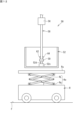
図12は、他の実施形態の変形例に係るコンテナ装置50の要部を示す図である。図12では、コンテナ52を断面図として示している。
この変形例では、連結シャフト58が伸縮せず、運搬車両Rの天板Ruが上下方向に昇降可能である点において上記他の実施形態と相違する。
この変形例では、連結シャフト58が伸縮せず、運搬車両Rの天板Ruが上下方向に昇降可能である点において上記他の実施形態と相違する。
図12に示すように、運搬車両Rは、天板Ruを昇降させる昇降機構Reを備える。
昇降機構Reは、リンク機構RLと、アクチュエータRaと、を備える。リンク機構RLは、天板Ruと、運搬車両Rの車体上面と、の間に設けられている。リンク機構RLは、上下方向に伸縮可能に構成されている。アクチュエータRaは、リンク機構RLの基端部に設けられ、リンク機構RLの伸縮動作を駆動する。アクチュエータRaは、運搬車両Rの制御装置によって制御可能である。よって、昇降機構Reの動作制御は、運搬車両Rの制御装置によって行われる。昇降機構Reの動作制御は、運搬車両Rを制御する制御装置4によって行われることもある。
この場合、天板Ruを上昇させた上で、果実が積載されたコンテナ52を天板Ruに搭載することができる。
昇降機構Reは、リンク機構RLと、アクチュエータRaと、を備える。リンク機構RLは、天板Ruと、運搬車両Rの車体上面と、の間に設けられている。リンク機構RLは、上下方向に伸縮可能に構成されている。アクチュエータRaは、リンク機構RLの基端部に設けられ、リンク機構RLの伸縮動作を駆動する。アクチュエータRaは、運搬車両Rの制御装置によって制御可能である。よって、昇降機構Reの動作制御は、運搬車両Rの制御装置によって行われる。昇降機構Reの動作制御は、運搬車両Rを制御する制御装置4によって行われることもある。
この場合、天板Ruを上昇させた上で、果実が積載されたコンテナ52を天板Ruに搭載することができる。
〔その他〕
なお、今回開示された実施の形態はすべての点で例示であって制限的なものではないと考えられるべきである。
例えば、上記実施形態では、太陽光発電パネル2を支持する架台6にレールユニット7を設けた場合を例示したが、架台6の一部である架台6の梁フレーム6bおよび支持フレーム6cが作業ユニット10のレールの機能を有していてもよい。
この場合、架台6以外に別途専用のレールを設置することなく、農作業装置22(作業ユニット10)を設置することができる。
また、上記実施形態では、農作業システム1が太陽光発電パネル2を備える場合を例示したが、本システムは、太陽光発電パネル2を備えていなくてもよい。
なお、今回開示された実施の形態はすべての点で例示であって制限的なものではないと考えられるべきである。
例えば、上記実施形態では、太陽光発電パネル2を支持する架台6にレールユニット7を設けた場合を例示したが、架台6の一部である架台6の梁フレーム6bおよび支持フレーム6cが作業ユニット10のレールの機能を有していてもよい。
この場合、架台6以外に別途専用のレールを設置することなく、農作業装置22(作業ユニット10)を設置することができる。
また、上記実施形態では、農作業システム1が太陽光発電パネル2を備える場合を例示したが、本システムは、太陽光発電パネル2を備えていなくてもよい。
また、上記実施形態では、圃場Fで栽培されている作物Cの果実がブドウである場合を例示したが、これに限定されず、その他の果樹や、野菜等を作物Cとして栽培してもよい。
また、本実施形態では、圃場Fの日射量を調整する調整機構として仰角可変機構20を用いた場合を例示した。しかし、調整機構は、圃場Fの日射量を調整することができる機構であればよく、例えば、太陽光発電パネル2を透明なパネルで構成し、調整機構として、調光機能を有するフィルムを用いてもよい。この場合、調光フィルムは、透明な太陽光発電パネル2に重ね合わせて用いられる。これにより、太陽光発電パネル2および調光フィルムを通過することで適度に調光された太陽光が、圃場Fに照射される。
本発明の範囲は、上記した意味ではなく、請求の範囲によって示され、請求の範囲と均等の意味、および範囲内でのすべての変更が含まれることが意図される。
1 農作業システム
2 太陽光発電パネル
2a セル
2b パネルフレーム
4 制御装置
4a 処理部
4b 記憶部
4c 入出力部
6 架台
6a 支柱
6b 梁フレーム
6c 支持フレーム
7 レールユニット
8 レール
8a 第1レール
8a1 端部
8a2 スリット
8b 第2レール
8b1 開口部
8c 逃げ部
8d 内面
8k 内部空間
8r 底板
8r1 底板
8r2 底板
8s スリット
8s1 スリット
8s2 スリット
8s3 連結スリット
10 作業ユニット
14 環境検出部
16 カメラ
18 無線通信機(アクセスポイント)
20 仰角可変機構
20a 台座
20b 支持部
20c アクチュエータ
22 農作業装置
24 移動機構
26 コントロールボックス
30 アーム
30a 関節
32 エンドエフェクタ
32a エンドエフェクタ
40 本体部
42 車輪
43 無線通信機
44 モータ
45 蓄電池
46 制御装置
46a 処理部
46b 記憶部
47 タンク
47a 受取口
48 搾りかす貯蔵タンク
49 果汁貯蔵タンク
50 コンテナ装置
52 コンテナ
52a 側壁部
52a1 側板
52b 底部
52b1 底板
52c 梁部
52d 突起部
54 移動機構
56 コントロールボックス
57 ヒンジ
58 連結シャフト
58a 内筒部
58b 外筒部
59 連結部
60 移送機構
60a ロック装置
60b 閉鎖装置
62 測定部
64 検出部
70 運搬用コンテナ
70a 受取口
100 太陽光発電機構
C 作物
F 圃場
P1 位置
P2 位置
P3 位置
R 運搬車両
R1 第1運搬車両
R2 第2運搬車両
RL リンク機構
Ra アクチュエータ
Re 昇降機構
Ru 天板
2 太陽光発電パネル
2a セル
2b パネルフレーム
4 制御装置
4a 処理部
4b 記憶部
4c 入出力部
6 架台
6a 支柱
6b 梁フレーム
6c 支持フレーム
7 レールユニット
8 レール
8a 第1レール
8a1 端部
8a2 スリット
8b 第2レール
8b1 開口部
8c 逃げ部
8d 内面
8k 内部空間
8r 底板
8r1 底板
8r2 底板
8s スリット
8s1 スリット
8s2 スリット
8s3 連結スリット
10 作業ユニット
14 環境検出部
16 カメラ
18 無線通信機(アクセスポイント)
20 仰角可変機構
20a 台座
20b 支持部
20c アクチュエータ
22 農作業装置
24 移動機構
26 コントロールボックス
30 アーム
30a 関節
32 エンドエフェクタ
32a エンドエフェクタ
40 本体部
42 車輪
43 無線通信機
44 モータ
45 蓄電池
46 制御装置
46a 処理部
46b 記憶部
47 タンク
47a 受取口
48 搾りかす貯蔵タンク
49 果汁貯蔵タンク
50 コンテナ装置
52 コンテナ
52a 側壁部
52a1 側板
52b 底部
52b1 底板
52c 梁部
52d 突起部
54 移動機構
56 コントロールボックス
57 ヒンジ
58 連結シャフト
58a 内筒部
58b 外筒部
59 連結部
60 移送機構
60a ロック装置
60b 閉鎖装置
62 測定部
64 検出部
70 運搬用コンテナ
70a 受取口
100 太陽光発電機構
C 作物
F 圃場
P1 位置
P2 位置
P3 位置
R 運搬車両
R1 第1運搬車両
R2 第2運搬車両
RL リンク機構
Ra アクチュエータ
Re 昇降機構
Ru 天板
Claims (13)
- 作物を栽培する圃場の上方に設けられた複数のレールを含むレール網と、
前記複数のレールに吊り下げられ、前記作物を収穫することで得た収穫物が積載される収穫位置から、前記レール網の縁部に位置する所定の停止位置へ、前記複数のレールに沿って移動可能なコンテナ装置と、を備える
収穫物の搬送システム。 - 前記コンテナ装置は、
積載される前記収穫物の積載量を測定する測定部と、
前記積載量が所定の条件を満たすと、前記停止位置へ向けて前記収穫物を移動させる移動機構と、を備える
請求項1に記載の収穫物の搬送システム。 - 前記所定の停止位置の下方に配置された、前記収穫物を貯蔵するタンクをさらに備え、
前記コンテナ装置は、
前記収穫物が積載されるコンテナと、
前記コンテナの底部を開閉することで前記収穫物を下方向へ落下させる移送機構と、を備え、
前記タンクは、前記コンテナから落下する前記収穫物を受け取る受取口を備える
請求項1または請求項2に記載の収穫物の搬送システム。 - 前記所定の停止位置の下方に設けられた停車位置に停車可能な1または複数の収穫物運搬車両をさらに備え、
前記1または複数の収穫物運搬車両は、前記コンテナ装置が有する前記収穫物積載用のコンテナが搭載される天板を備える
請求項1に記載の収穫物の搬送システム。 - 前記コンテナ装置は、
前記コンテナを前記レールに沿って移動させる移動機構と、
前記コンテナと前記移動機構とを解除可能に連結する連結部と、を備え、
前記コンテナが前記所定の停止位置に位置しかつ前記1または複数の収穫物運搬車両が前記停車位置に位置する場合、前記連結部による連結が解除される
請求項4に記載の収穫物の搬送システム。 - 前記コンテナ装置は、前記連結部と前記移動機構との間に設けられる伸縮可能な連結シャフトを備える
請求項5に記載の収穫物の搬送システム。 - 前記1または複数の収穫物運搬台車は、前記天板を昇降させる昇降機構をさらに備える
請求項5に記載の収穫物の搬送システム。 - 前記複数の収穫物運搬車両は、前記コンテナが搭載されていない第1収穫物運搬車両と、空の前記コンテナが搭載された第2収穫物運搬車両と、を含み、
前記第1収穫物運搬車両は、前記停車位置に停車したときに前記コンテナ装置から連結が解除された前記コンテナを受け取って移動し、
前記第2収穫物運搬車両は、第1収穫物運搬車両が移動した後の前記停車位置に停車し、
前記空のコンテナは、前記第2収穫物運搬車両が前記停車位置に停車すると、前記連結部によって前記移動機構に連結される
請求項5から請求項7のいずれか一項に記載の収穫物の搬送システム。 - 前記所定の停止位置の下方に設けられた停車位置に停車可能な収穫物運搬車両をさらに備え、
前記コンテナ装置は、前記コンテナ装置が有する前記収穫物積載用のコンテナの底部を開閉することで前記収穫物を下方向へ落下させる移送機構を備え、
前記収穫物運搬車両は、前記コンテナから落下する前記収穫物を受け取る受取口を有する運搬用コンテナを備える
請求項1に記載の収穫物の搬送システム。 - 前記複数のレールに沿って移動する農作業装置をさらに備え、
前記移動機構は、前記収穫物量が所定の条件を満たすまで、前記農作業装置を追従する
請求項2に記載の収穫物の搬送システム。 - 前記コンテナ装置は、積載される前記収穫物の積載量を測定する測定部を備え、
前記積載量を外部へ出力する出力部をさらに備える
請求項1から請求項10のいずれか一項に記載の収穫物の搬送システム。 - 前記コンテナ装置は、前記収穫物の状態を検出する検出部をさらに備え、
前記出力部は、前記積載量とともに前記状態を出力する
請求項11に記載の収穫物の搬送システム。 - 作物を栽培する圃場の上方に設けられてレール網を構成する複数のレールに吊り下げられ前記複数のレールに沿って移動するコンテナ装置であって、
前記作物を収穫することで得た収穫物が積載されるコンテナと、
前記コンテナを前記レールに沿って移動させる移動機構と、
前記コンテナに積載される前記収穫物の積載量を測定する測定部と、
前記積載量が所定の条件を満たすと、前記レール網の縁部に位置する所定の停止位置へ前記コンテナを移動させ停止するように前記移動機構を制御する制御部と、を備える
コンテナ装置。
Applications Claiming Priority (2)
| Application Number | Priority Date | Filing Date | Title |
|---|---|---|---|
| JP2023220678A JP2025103340A (ja) | 2023-12-27 | 2023-12-27 | 収穫物の搬送システムおよびコンテナ装置 |
| JP2023-220678 | 2023-12-27 |
Publications (1)
| Publication Number | Publication Date |
|---|---|
| WO2025142152A1 true WO2025142152A1 (ja) | 2025-07-03 |
Family
ID=96218842
Family Applications (1)
| Application Number | Title | Priority Date | Filing Date |
|---|---|---|---|
| PCT/JP2024/039868 Pending WO2025142152A1 (ja) | 2023-12-27 | 2024-11-08 | 収穫物の搬送システムおよびコンテナ装置 |
Country Status (2)
| Country | Link |
|---|---|
| JP (1) | JP2025103340A (ja) |
| WO (1) | WO2025142152A1 (ja) |
Citations (3)
| Publication number | Priority date | Publication date | Assignee | Title |
|---|---|---|---|---|
| WO2020158248A1 (ja) * | 2019-01-31 | 2020-08-06 | 株式会社クボタ | 作業装置 |
| KR20210024786A (ko) * | 2019-08-26 | 2021-03-08 | 목포대학교산학협력단 | 절화류의 천장형 습식 수확 장치 |
| WO2021144955A1 (ja) * | 2020-01-17 | 2021-07-22 | Agrist株式会社 | 取得装置及び取得システム |
-
2023
- 2023-12-27 JP JP2023220678A patent/JP2025103340A/ja active Pending
-
2024
- 2024-11-08 WO PCT/JP2024/039868 patent/WO2025142152A1/ja active Pending
Patent Citations (3)
| Publication number | Priority date | Publication date | Assignee | Title |
|---|---|---|---|---|
| WO2020158248A1 (ja) * | 2019-01-31 | 2020-08-06 | 株式会社クボタ | 作業装置 |
| KR20210024786A (ko) * | 2019-08-26 | 2021-03-08 | 목포대학교산학협력단 | 절화류의 천장형 습식 수확 장치 |
| WO2021144955A1 (ja) * | 2020-01-17 | 2021-07-22 | Agrist株式会社 | 取得装置及び取得システム |
Also Published As
| Publication number | Publication date |
|---|---|
| JP2025103340A (ja) | 2025-07-09 |
Similar Documents
| Publication | Publication Date | Title |
|---|---|---|
| CN111620024B (zh) | 一种搬运机器人、取货箱方法及放货箱方法 | |
| US11713193B2 (en) | Material handling apparatus having seperate workstation and method of use | |
| US20220354070A1 (en) | System and Method for Harvesting and Packing Mushrooms | |
| US20220087105A1 (en) | System and method for autonomous harvester installation and farm harvesting operation | |
| US20210101764A1 (en) | Automated packing cart | |
| DE102020209746A1 (de) | Unbemanntes bodengebundenes fahrzeug zur aufrechterhaltungvon hygiene und verfahren zur verbesserung von hygienebedingungen | |
| CN115989750A (zh) | 一种莲蓬自动采摘系统及莲蓬采摘方法 | |
| WO2022214580A1 (en) | A container handling vehicle for handling a delivery container stored within a storage container and a method thereof | |
| CN108082879A (zh) | 一种水果柔性输送自动收集装置 | |
| CN118872486A (zh) | 一种农保机器人及控制方法 | |
| CN118592208A (zh) | 系留无人机式采摘机器人及控制方法 | |
| CN118743354A (zh) | 一种采摘机器人及控制方法 | |
| CN118575661A (zh) | 一种采摘机器人的中柱滑轨结构及控制方法 | |
| US20240189982A1 (en) | Robotic system with object handling mechanism for loading and unloading of cargo carriers | |
| CN118556507A (zh) | 采摘机器人的收果装置及控制方法 | |
| WO2025142152A1 (ja) | 収穫物の搬送システムおよびコンテナ装置 | |
| US20260028075A1 (en) | Vehicles including truck assemblies configured to selectively decouple a wheel of the truck assembly | |
| CN118651412B (zh) | 一种基于飞行平台的自主式载荷输送装置 | |
| CN207956901U (zh) | 一种水果柔性输送自动收集装置 | |
| CN116374046A (zh) | 一种无人驾驶配送车 | |
| CN120731307A (zh) | 用于运输砌块的穿梭装置 | |
| WO2025142107A1 (ja) | 農作業システム | |
| KR102922331B1 (ko) | 수직재배용 자동 과실 수확 로봇 | |
| GB2334192A (en) | Harvesting apparatus | |
| RU237733U1 (ru) | Полуавтоматизированный погрузчик |
Legal Events
| Date | Code | Title | Description |
|---|---|---|---|
| 121 | Ep: the epo has been informed by wipo that ep was designated in this application |
Ref document number: 24912045 Country of ref document: EP Kind code of ref document: A1 |