WO2025142102A1 - 原油回収効果の評価装置および原油回収効果の評価方法 - Google Patents
原油回収効果の評価装置および原油回収効果の評価方法 Download PDFInfo
- Publication number
- WO2025142102A1 WO2025142102A1 PCT/JP2024/038523 JP2024038523W WO2025142102A1 WO 2025142102 A1 WO2025142102 A1 WO 2025142102A1 JP 2024038523 W JP2024038523 W JP 2024038523W WO 2025142102 A1 WO2025142102 A1 WO 2025142102A1
- Authority
- WO
- WIPO (PCT)
- Prior art keywords
- crude oil
- test specimen
- salinity
- low
- salinity water
- Prior art date
- Legal status (The legal status is an assumption and is not a legal conclusion. Google has not performed a legal analysis and makes no representation as to the accuracy of the status listed.)
- Pending
Links
Images


Classifications
-
- E—FIXED CONSTRUCTIONS
- E21—EARTH OR ROCK DRILLING; MINING
- E21C—MINING OR QUARRYING
- E21C50/00—Obtaining minerals from underwater, not otherwise provided for
-
- G—PHYSICS
- G01—MEASURING; TESTING
- G01N—INVESTIGATING OR ANALYSING MATERIALS BY DETERMINING THEIR CHEMICAL OR PHYSICAL PROPERTIES
- G01N13/00—Investigating surface or boundary effects, e.g. wetting power; Investigating diffusion effects; Analysing materials by determining surface, boundary, or diffusion effects
- G01N13/04—Investigating osmotic effects
-
- G—PHYSICS
- G01—MEASURING; TESTING
- G01N—INVESTIGATING OR ANALYSING MATERIALS BY DETERMINING THEIR CHEMICAL OR PHYSICAL PROPERTIES
- G01N33/00—Investigating or analysing materials by specific methods not covered by groups G01N1/00 - G01N31/00
- G01N33/22—Fuels; Explosives
-
- G—PHYSICS
- G01—MEASURING; TESTING
- G01N—INVESTIGATING OR ANALYSING MATERIALS BY DETERMINING THEIR CHEMICAL OR PHYSICAL PROPERTIES
- G01N33/00—Investigating or analysing materials by specific methods not covered by groups G01N1/00 - G01N31/00
- G01N33/24—Earth materials
Definitions
- the present invention relates to an apparatus and method for evaluating the effectiveness of crude oil recovery using low-salinity water flooding.
- the tertiary recovery method which recovers the crude oil trapped in the oil reservoir after secondary recovery, is called enhanced oil recovery (EOR).
- EOR enhanced oil recovery
- Low-salinity water flooding is a method for recovering crude oil trapped in an oil reservoir by injecting salt-containing water with a lower salinity than the brine contained in the oil reservoir, or salt-free water, into the oil reservoir.
- Non-Patent Document 1 describes the recovery mechanism proposed for low-salinity water flooding.
- Non-Patent Documents 2 and 3 describe experimental evidence of enhanced oil recovery due to chemical penetration in low-salinity water flooding.
- An effective osmotic pressure ⁇ P measuring device for measuring the pressure of the high-salinity water and the pressure of the low-salinity water in a test specimen that is made of high-salinity water having a first salinity and rock containing crude oil and that is in contact with low-salinity water having a second salinity less than the first salinity, and for calculating an effective osmotic pressure ⁇ P, which is the pressure difference between the high-salinity water and the low-salinity water, for each unit time;
- a crude oil movement amount ⁇ V measurement device that calculates a crude oil movement amount ⁇ V caused by a salinity difference ⁇ C between the first salinity and the second salinity, the crude oil movement amount ⁇ V being calculated based on at least one measurement result selected from the following (1) to (3):
- An evaluation device for evaluating the presence or absence of a crude oil recovery effect, the evaluation device determining that there is a crude oil recovery effect due to chemical penetration in
- the crude oil movement amount ⁇ V measuring device calculates the crude oil movement amount ⁇ V based on the measurement result of (1), The evaluation device for evaluating the crude oil recovery effect described in [1].
- the apparatus for evaluating a crude oil recovery effect described in [1] wherein the test specimen is in contact with the low-salinity water by contacting a rock containing the low-salinity water.
- a method for evaluating the effect of crude oil recovery comprising: a step of evaluating the presence or absence of an effect of crude oil recovery, and a third step of determining that there is an effect of crude oil recovery due to chemical penetration in
- the effective osmotic pressure ⁇ P is greater than 0, the effective osmotic pressure ⁇ P changes per unit time, and the presence of the crude oil movement amount ⁇ V cannot be confirmed;
- the effective osmotic pressure ⁇ P is greater than 0, the effective osmotic pressure ⁇ P changes per unit time, and the presence of the crude oil displacement amount ⁇ V can be confirmed;
- the effective osmotic pressure ⁇ P is 0, and the presence of the crude oil displacement amount ⁇ V can be confirmed.
- the X-ray CT value of the test specimen is measured every unit time using an X-ray CT measuring device and/or the resistivity value of the test specimen is measured every unit time using a resistivity measuring device, and the ratio of the amount of crude oil and the amount of water in the test specimen is calculated every unit time based on the X-ray CT value measured every unit time of the test specimen and/or the resistivity value measured every unit time of the test specimen.
- the test specimen is a rock taken from an oil reservoir for which the crude oil recovery effect is to be evaluated, or a rock simulating the oil reservoir,
- the crude oil recovery effect evaluation device and crude oil recovery effect evaluation method of the present invention it is possible to evaluate with high accuracy whether a crude oil recovery effect resulting from chemical penetration in low-salinity water flooding can be obtained for a test specimen made of rock. Therefore, according to the present invention, for example, by using rocks collected from an oil reservoir that is the target of crude oil recovery as the test specimen, it is possible to evaluate with high accuracy whether a crude oil recovery effect can be obtained when crude oil remaining in the oil reservoir is recovered by low-salinity water flooding.
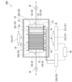
- FIG. 1 is a schematic diagram for explaining an evaluation device for the crude oil recovery effect due to chemical permeation in a low-salinity water flooding method of the first embodiment.
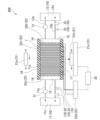
- FIG. 1 is a schematic diagram for explaining an evaluation device for the crude oil recovery effect due to chemical permeation in a low-salinity water flooding method according to a second embodiment.
- FIG. 11 is a schematic diagram for explaining an evaluation device for the crude oil recovery effect due to chemical permeation in a low-salinity water flooding method according to the third embodiment.
- FIG. 11 is a schematic diagram for explaining an evaluation device for the crude oil recovery effect due to chemical permeation in a low-salinity water flooding method according to the fourth embodiment.
- FIG. 1 is a schematic diagram for explaining an evaluation device for the crude oil recovery effect due to chemical permeation in a low-salinity water flooding method of the first embodiment.
- FIG. 1 is a schematic diagram for explaining an evaluation device for the crude oil recovery effect due to chemical permeation in a low-
- the inventors have conducted extensive research to solve the above problems and to enable a highly accurate evaluation of the oil recovery effect resulting from chemical penetration in low-salinity water flooding using test specimens made of rocks extracted from oil reservoirs that are the target of oil recovery, as described below, focusing on the enhanced recovery mechanism of low-salinity water flooding.
- ⁇ P an effective osmotic pressure
- ⁇ P an effective osmotic pressure
- chemical osmosis occurs, driven by the chemical potential, and water moves from the low-salinity water to the high-salinity water.
- Chemical osmosis occurs through semipermeable membranes such as clay minerals contained in the rock that forms the test specimen, water films that exist at the boundaries between the crude oil and clay minerals, and the crude oil itself.
- test specimens which are rocks containing high-salinity water and crude oil
- water infiltrates from the low-salinity water through the semipermeable membrane due to chemical osmosis, generating an effective osmotic pressure ⁇ P in the high-salinity water.
- the effective osmotic pressure ⁇ P generated in the high-salinity water also generates a pressure flow from the high-salinity water to the low-salinity water in the mixture of crude oil and pore water.
- a mixture of crude oil and pore water with the same volume as the water that infiltrated into the rock due to chemical osmosis seeps out from the edge of the rock that comes into contact with the low-salinity water.
- the inventors considered that if the effective osmotic pressure ⁇ P shown below for a test specimen made of rock exceeds 0, the test specimen can be evaluated as a test specimen that can obtain a crude oil recovery effect by chemical penetration in a low-salinity water flood.
- a test specimen made of high-salinity water and rock containing crude oil is placed in contact with low-salinity water, and if the effective osmotic pressure ⁇ P generated by the chemical potential difference between the high-salinity water and the low-salinity water exceeds 0, a pressure flow of a mixture of crude oil and pore water from the high-salinity water to the low-salinity water occurs in the test specimen, driven by the effective osmotic pressure ⁇ P.
- the network is composed of pores of various sizes, so the viscous resistance and threshold pressure Pth are not uniform.
- a large driving force large effective osmotic pressure ⁇ P
- the mixture of crude oil and pore water tries to pass through a small pore, if the mixture does not have an effective osmotic pressure ⁇ P that matches the threshold pressure Pth of the pore, the movement of the mixture of crude oil and pore water will temporarily stop.
- the effective osmotic pressure ⁇ P repeatedly increases and decreases depending on the viscous resistance of the pores through which the mixture of crude oil and pore water is trying to pass and the threshold pressure Pth.
- crude oil present in pores (small pores) with a large threshold pressure Pth that exceeds the driving force of the effective osmotic pressure ⁇ P which repeatedly increases and decreases, does not move even if chemical permeation occurs in that pore from low-salinity water to high-salinity water, and remains inside the rock.
- the effective osmotic pressure ⁇ P is greater than 0 and increases and decreases over time (in other words, changes over time)
- the rock that contained the test specimen can be evaluated as being capable of achieving the effect of recovering crude oil by chemical infiltration during low-salinity water flooding.
- the inventors also focused on the size of the pores in test specimens made of rock and conducted extensive research into the effectiveness of chemical infiltration in recovering crude oil when using low-salinity water flooding on test specimens. As a result, they found that when the test specimen is a rock with relatively large pores (for example, pores with a shortest distance between opposing wall surfaces of 1 ⁇ m or more), the effective osmotic pressure ⁇ P may be 0 inside the test specimen, even though chemical infiltration is occurring due to the salinity difference ⁇ C.
- the effective osmotic pressure ⁇ P is expressed according to the viscous resistance and threshold pressure Pth, which depend on the size of the pores, and the larger the pores, the smaller the effective osmotic pressure ⁇ P at which the mixture of crude oil and water undergoes pressure flow. More specifically, inside the test specimen, a localized internal effective osmotic pressure is generated according to the size of the pores, but because the viscous resistance is small, the mixture of crude oil and water moves immediately, and the localized internal effective osmotic pressure dissipates.
- the effective osmotic pressure ⁇ P which is the pressure difference between the high-salinity water present near the outer surface of the test specimen or the high-salinity water removed from the test specimen to the outside, and the low-salinity water present near the outer surface of the test specimen or the low-salinity water removed from the test specimen to the outside, may also be below the detection limit of the pressure measurement device.
- the amount of oil movement ⁇ V is the amount of oil movement ⁇ V caused by chemical osmosis caused by the salinity difference ⁇ C.
- the amount of oil movement ⁇ V is calculated based on at least one measurement result selected from the following (1) to (3).
- the amount of crude oil movement ⁇ V can be calculated based on at least one of the measurement results (1) to (3) above, it can be evaluated that there is an oil recovery effect due to chemical osmosis in low-salinity water flooding even if the effective osmotic pressure ⁇ P is 0. Furthermore, the greater the calculated amount of crude oil movement ⁇ V, the higher the oil recovery effect due to chemical osmosis in low-salinity water flooding can be evaluated.
- the test specimen is a rock with relatively small voids (for example, a void in which the shortest distance between opposing wall surfaces is less than 1 ⁇ m)
- the amount of crude oil movement ⁇ V is small, so that the amount of crude oil movement ⁇ V cannot be measured or the measurement error of the amount of crude oil movement ⁇ V becomes large. Therefore, it is difficult to use the amount of crude oil movement ⁇ V to evaluate with sufficient accuracy whether or not a crude oil recovery effect can be obtained by low-salinity water flooding. Therefore, if the test specimen is a rock with relatively small voids and the effective osmotic pressure ⁇ P is 0, the crude oil recovery effect due to chemical penetration in low-salinity water flooding cannot be obtained.
- the inventors conducted extensive research in order to develop a method for evaluating with high accuracy whether or not a crude oil recovery effect resulting from chemical penetration can be achieved in low-salinity water flooding, regardless of whether the rock specimen has large or small pores.
- the inventors discovered that for a test specimen consisting of high-salinity water and rock containing crude oil collected from an oil reservoir that is the target of crude oil recovery, the effective osmotic pressure ⁇ P was calculated per unit time while the specimen was in contact with low-salinity water, and based on the amount of crude oil movement ⁇ V, if at least one of the following conditions (i) to (iii) is satisfied, it can be determined that there is a crude oil recovery effect due to chemical penetration in the low-salinity water flooding method for the test specimen, and thus completed the present invention.
- the effective osmotic pressure ⁇ P is greater than 0, the effective osmotic pressure ⁇ P changes per unit time, and the presence of the crude oil movement amount ⁇ V cannot be confirmed.
- the effective osmotic pressure ⁇ P is greater than 0, the effective osmotic pressure ⁇ P changes per unit time, and the presence of the crude oil movement amount ⁇ V can be confirmed.
- the effective osmotic pressure ⁇ P is 0, and the presence of the crude oil displacement amount ⁇ V can be confirmed.
- FIG. 1 is a schematic diagram for explaining an evaluation device for the effect of crude oil recovery due to chemical permeation in a low-salinity water flooding method according to the first embodiment.
- a test specimen 1 consisting of high-salinity water 11c and rock containing crude oil is used as an evaluation target.
- the test specimen 1 is a rock for which the effect of crude oil recovery due to chemical penetration in a low-salinity water flooding is to be evaluated, and is preferably a rock collected from an oil reservoir that is the target of crude oil recovery.
- the test specimen 1 may also be a rock simulating an oil reservoir that is the target of crude oil recovery.
- the test specimen 1 contains high salinity water 11c, which is the pore water of an oil reservoir.
- the test specimen 1 may contain salinity water prepared using sodium chloride or the like, instead of the high salinity water 11c, which is the pore water of an oil reservoir, and which has the same amount of dissolved substances as the pore water of an oil reservoir.
- the crude oil contained in the test specimen 1 and which is the subject of the crude oil recovery is preferably the crude oil contained in the rock from which the crude oil recovery effect is to be evaluated, but may be an oil simulating the crude oil impregnated in the test specimen 1.
- the oil simulating the crude oil include liquid paraffin and toluene.
- the type of rock that is the test specimen 1 is not particularly limited, and examples thereof include mudstone, sandstone, carbonate rock, and the like.
- the specimen 1 shown in Fig. 1 has a substantially cylindrical shape.
- the specimen 1 is sealed by a covering sheet 16 that covers the entire side surface of the specimen 1 and end caps 15 that are respectively disposed on both end surfaces of the specimen 1.
- the cover sheet 16 is made of a flexible sheet having water resistance, chemical resistance, and oil resistance, such as a rubber sheet made of fluororubber.
- the end cap 15 may be made of a resin such as polyether ether ketone (PEEK).
- PEEK polyether ether ketone
- the end cap 15 is generally circular in plan view.
- the end cap 15 may have a plurality of grooves on the surface facing the test specimen 1, for diffusing the high salinity water 11c or the low salinity water 12c in the diameter direction of the test specimen 1.
- an end cap 15 that has the function of a water distribution plate and also serves as a water distribution plate may be used.
- such an end cap 15 may have a plurality of grooves on the surface on the side of the test specimen 1 for diffusing the high salinity water 11c or low salinity water 12c in the diameter direction of the test specimen 1 and bringing it into contact with the test specimen 1.
- the salinity measuring device 32 for the high-salinity water 11c and the low-salinity water 12c a known salinity measuring device such as an electrical conductivity electrode can be used.
- the salinity of the high salinity water 11c and the low salinity water 12c measured by the salinity measurement device are input to a salinity difference ⁇ C calculation device (not shown).
- the salinity difference ⁇ C calculation device calculates the salinity difference ⁇ C between the high-salinity water 11c and the low-salinity water 12c per unit time by inputting the salinity signal of the high-salinity water 11c and the salinity signal of the low-salinity water 12c measured by the salinity measurement device 32.
- the salinity difference ⁇ C is calculated per unit time.
- the salinity difference ⁇ C calculated by the salinity difference ⁇ C calculation device is input to the evaluation device 30.
- the function of the effective osmotic pressure ⁇ P calculation device to calculate the effective osmotic pressure ⁇ P, which is the pressure difference between the high salinity water 11c and the low salinity water 12c, per unit time, and the function of the salinity difference ⁇ C calculation device to calculate the salinity difference ⁇ C per unit time are realized, for example, by functions provided in the central processing unit of a computer.
- the crude oil movement amount ⁇ V measuring device in the crude oil recovery effect evaluation device 100 of this embodiment is a device that calculates the crude oil movement amount ⁇ V caused by chemical osmosis that occurs due to the salinity difference ⁇ C between the salinity (first salinity) of the high salinity water 11c and the salinity (second salinity) of the low salinity water 12c.
- a crude oil movement amount ⁇ V measuring device will be described as a device that calculates the crude oil movement amount ⁇ V based on the measurement results of calculating the ratio of the crude oil amount and the water amount in the test body 1 per unit time.
- the crude oil movement amount ⁇ V measuring device of this embodiment has an X-ray CT measuring device 21, a resistivity measuring device 22, and a crude oil movement amount ⁇ V calculation device (not shown), as shown in Fig. 1.
- a case will be described as an example in which the crude oil movement amount ⁇ V measuring device has the X-ray CT measuring device 21 and the resistivity measuring device 22, but it may have only one of the X-ray CT measuring device 21 and the resistivity measuring device 22.
- the X-ray CT measurement device 21 measures the X-ray CT value of the test piece 1 per unit time. As shown in FIG. 1, the X-ray CT measurement device 21 includes an X-ray irradiation device 21a, a detector 21b, and a CT value calculation device 21c. 1, the X-ray irradiation device 21a rotates around the test piece 1 in a circumferential direction along the side surface of the cylindrical test piece 1 contained in the container 13 and irradiates the test piece 1 with X-rays while moving along the length direction of the test piece 1.
- the detector 21b is disposed opposite the X-ray irradiation device 21a with the test piece 1 in between, and detects the amount of X-rays transmitted through the test piece 1 while rotating around the test piece 1 in a circumferential direction along the side surface of the cylindrical test piece 1 together with the X-ray irradiation device 21a and moving along the length direction of the test piece 1.
- the CT value calculation device 21c calculates an X-ray CT value corresponding to the density of the test piece 1 from the detection result detected by the detector 21b.
- the X-ray irradiation device 21a and the detector 21b rotate in the circumferential direction around the test piece 1 along the side of the test piece 1 contained in the container 13 and move along the length of the test piece 1, but the way in which the X-ray irradiation device 21a and the detector 21b are moved is not particularly limited as long as it is possible to measure the X-ray CT value of the entire test piece 1.
- the X-ray irradiation device 21a may rotate along the length of the cylindrical test piece 1 contained in the container 13 and irradiate the test piece 1 with X-rays while moving along the diameter of the test piece 1.
- the detector 21b is disposed opposite the X-ray irradiation device 21a with the test piece 1 in between, and detects the amount of X-rays that have passed through the test piece 1 while rotating along the length of the cylindrical test piece 1 together with the X-ray irradiation device 21a and moving along the diameter of the test piece 1 together with the X-ray irradiation device 21a.
- the X-ray CT value is measured by the X-ray CT measurement device 21 every unit time and inputted to a calculation device for calculating the amount of movement of crude oil ⁇ V, which will be described later.
- the frequency of measuring the X-ray CT value of the test piece 1 can be, for example, every 5 minutes to every hour, and may be constant or may be changed as necessary. It is preferable that the measurement of the X-ray CT value of the test specimen 1 is started when the test specimen 1 is brought into contact with the low-salinity water 12c, and is ended after it is confirmed that no change is observed in the X-ray CT value. In other words, it is preferable that the measurement of the X-ray CT value of the test specimen 1 is continuously performed every unit time as long as the X-ray CT value continues to increase or decrease.
- X-ray CT measurement device 21 for example, a commercially available X-ray CT measurement device, such as one used for medical purposes, can be used.
- a microfocus X-ray CT measurement device or the like may also be used.
- the movement of crude oil can be evaluated using not only the X-ray CT value of the test piece 1 but also high-resolution images.
- the X-ray CT measuring device 21 may be, for example, an X-ray CT measuring device having a base with a table on which the test piece 1 contained in the container 13 is rotatably placed, and an X-ray irradiator 21a and detector 21b that rotate around the test piece 1 around an axis approximately perpendicular to the table and move in the vertical direction of the table.
- the resistivity measuring device 22 measures the resistivity value of the test piece 1 every unit time.
- the resistivity measuring device 22 has a pair of current electrodes 22a, 22b, a plurality of potential electrodes 22c (six in the example shown in FIG. 1), and a resistivity calculating device 22d that calculates the resistivity value from the potential difference between the pair of potential electrodes 22c.
- the pair of current electrodes 22a, 22b are made of a metal net having a substantially circular shape in a plan view, etc. As shown in FIG. 1 , the pair of current electrodes 22a, 22b are respectively installed at both ends in the longitudinal direction of the test piece 1, and are installed opposite each other so as to cover the end faces of the test piece 1. In the present embodiment, the current electrodes 22a and 22b are disposed facing each other so as to cover both end faces of the test piece 1 so that the resistivity value of the test piece 1 can be measured with high accuracy. However, the shape and the position of the current electrodes 22a and 22b can be appropriately changed as necessary.
- the current electrodes 22a and 22b may be disposed on the outer peripheral surface near both ends of the test piece 1 and may be linearly wound around the outer surface of the test piece 1 in the circumferential direction of the test piece 1. In this case, even if the X-ray CT measuring device 21 irradiates the cylindrical test piece 1 with X-rays from the length direction of the test piece 1, the current electrodes 22a and 22b are unlikely to affect the detection result of the amount of X-rays transmitted through the test piece 1.
- the multiple potential electrodes 22c are arranged between the pair of current electrodes 22a, 22b at approximately equal intervals in the longitudinal direction of the test piece 1, and are each wrapped around the outer surface of the test piece 1 in the circumferential direction of the test piece 1.
- the current electrodes 22a, 22b and the potential electrode 22c of the resistivity measuring device 22 are positioned in contact with the end face or side face of the test piece 1 through the covering sheet 16 and are sealed together with the test piece 1 by the covering sheet 16 and two end caps 15.
- the resistivity value is measured every unit time by the resistivity measuring device 22 and input to a calculation device for calculating the amount of movement of crude oil ⁇ V, which will be described later.
- the frequency of measuring the resistivity value of the test piece 1 can be, for example, every 5 minutes to 1 hour, and may be constant or may be changed as necessary. It is preferable that the measurement of the resistivity value of the test specimen 1 is started when the test specimen 1 is brought into contact with the low-salinity water 12c, and is ended after it is confirmed that the resistivity value is no longer changed. In other words, it is preferable that the measurement of the resistivity value of the test specimen 1 is continuously performed every unit time as long as the resistivity value continues to increase or decrease.
- the resistivity measuring device 22 may be a known device, such as a commercially available impedance measuring device.
- the crude oil movement amount ⁇ V calculation device calculates the ratio of the amount of crude oil and the amount of water in the test piece 1 per unit time based on the resistivity value measured per unit time of the test piece 1 and/or the X-ray CT value measured per unit time of the test piece 1, and calculates the amount of crude oil movement ⁇ V.
- the crude oil movement amount ⁇ V calculation device calculates the ratio of the amount of crude oil and the amount of water in the test piece 1 per unit time by inputting the signal of the X-ray CT value of the test piece 1 measured by the X-ray CT measurement device 21 and the signal of the resistivity value of the test piece 1 measured by the resistivity measurement device 22, and calculates the amount of crude oil movement ⁇ V based on the result.
- the amount of crude oil movement ⁇ V calculated by the crude oil movement amount ⁇ V calculation device is input to the evaluation device 30.
- the crude oil movement amount ⁇ V may be calculated based only on the resistivity value measured per unit time of the test body 1, or the crude oil movement amount ⁇ V may be calculated based only on the X-ray CT value measured per unit time of the test body 1. It is preferable that the crude oil movement amount ⁇ V calculation device calculates both the crude oil movement amount ⁇ V calculated based only on the resistivity value measured per unit time of the test body 1 and the crude oil movement amount ⁇ V calculated based only on the X-ray CT value measured per unit time of the test body 1, and inputs them to the evaluation device 30. This is because the evaluation device 30 can evaluate with higher accuracy whether or not a crude oil recovery effect can be obtained.
- the method for calculating the ratio of the amount of crude oil and the amount of water in the test specimen 1 per unit time from the X-ray CT value of the test specimen 1 is as follows. First, a plurality of rocks of the same type as the test specimen 1 are prepared. Then, after the pores present inside each rock are completely saturated with water, crude oil is injected into each rock at different pressures. In this way, a plurality of calibration curve test specimens with different mixture ratios of water and crude oil are prepared. The mixture ratio of water and crude oil is calculated from the porosity of the calibration curve test specimen and the densities of water and crude oil based on the measurement results of the mass difference of the calibration curve test specimen before and after the injection of water and crude oil.
- the test specimen for the calibration curve may be manufactured using salt water having a salinity equivalent to that of the high-salinity water 11c instead of water. In this case, the effect of crude oil recovery due to chemical penetration in the low-salinity water flooding method for the test specimen 1 can be evaluated more accurately.
- the X-ray CT values of the obtained calibration curve test specimens are measured in the same manner as the X-ray CT value of test specimen 1.
- a relational equation is obtained between the X-ray CT value and the ratio of the amount of crude oil to the amount of moisture.
- the ratio of the amount of crude oil to the amount of moisture in test specimen 1 is calculated from the X-ray CT value of test specimen 1.
- the ratio of the amount of crude oil to the amount of water in the test piece 1 is calculated per unit time from the resistivity value of the test piece 1 by the method shown below.
- the resistivity values of the above calibration curve test specimens are measured in the same manner as the resistivity value of test specimen 1. Using the results, a relational expression between the resistivity value and the ratio of the amount of crude oil to the amount of water is obtained. Using the relational expression thus obtained, the ratio of the amount of crude oil to the amount of water in test specimen 1 is calculated from the resistivity value of test specimen 1.
- the method for calculating the amount of movement of crude oil ⁇ V from the results of calculating the ratio of the amount of crude oil and the amount of water in the test piece 1 per unit time is specifically as follows. For example, after the test specimen 1 is brought into contact with the low-salinity water 12c, the amount of crude oil that has decreased over time is calculated from the ratio of the amount of crude oil to the amount of water calculated from the X-ray CT value obtained by the initial measurement and the ratio of the amount of crude oil to the amount of water calculated from the X-ray CT value obtained by measurement after a specified time, and this is taken as the amount of crude oil that has moved from the initial measurement until the specified time has elapsed, ⁇ V.
- the amount of crude oil that has decreased over time is calculated from the ratio of the amount of crude oil and the amount of water calculated from the resistivity value obtained by the initial measurement and the ratio of the amount of crude oil and the amount of water calculated from the resistivity value obtained by the measurement after a specified time, and this is taken as the amount of crude oil that has moved from the initial measurement until the specified time has elapsed, ⁇ V.
- the function of the crude oil movement amount ⁇ V calculation device to calculate the ratio of the amount of crude oil and the amount of water in the test piece 1 per unit time, and the function of calculating the amount of crude oil movement ⁇ V per unit time are realized, for example, by functions provided in the central processing unit of a computer.
- the evaluation device 30 evaluates the crude oil recovery effect due to chemical permeation in low-salinity water flooding for the test specimen 1 based on the effective osmotic pressure ⁇ P and the amount of crude oil movement ⁇ V. The evaluation device 30 determines that there is a crude oil recovery effect due to chemical penetration in low-salinity water flooding for the test specimen 1 when at least one of the conditions selected from (i) to (iii) below is satisfied.
- the effective osmotic pressure ⁇ P is greater than 0, the effective osmotic pressure ⁇ P changes per unit time, and the presence of the amount of crude oil movement ⁇ V cannot be confirmed.
- the effective osmotic pressure ⁇ P is greater than 0, the effective osmotic pressure ⁇ P changes per unit time, and the presence of a crude oil movement amount ⁇ V can be confirmed.
- the effective osmotic pressure ⁇ P is 0, and the presence of crude oil displacement ⁇ V can be confirmed.
- examples of rocks having relatively large voids include carbonate rocks and sandstone.
- Examples of relatively large voids include voids in which the shortest distance between opposing wall surfaces is 1 ⁇ m or more.
- a covering sheet 16 is placed over the entire side surface of the test specimen 1 on which the pair of current electrodes 22a, 22b and the multiple potential electrodes 22c are installed.
- a water distribution plate 14 and an end cap 15 are placed in this order on the outside of the current electrodes 22a, 22b installed on both end surfaces of the test specimen 1, and the covering sheet 16 and the end cap 15 seal the test specimen 1 on which the pair of current electrodes 22a, 22b and the multiple potential electrodes 22c are installed.
- the test body 1 shown in FIG. 3 is made of rock containing high salinity water 11c and crude oil, and has a generally cylindrical shape, similar to the test body 1 in the first embodiment shown in FIG. 1. Unlike the first embodiment, one end face of the test body 1 (the right end in FIG. 3) is in contact with rock 1a containing low salinity water 12c, which has a generally cylindrical shape and is coaxial with the test body 1 and has a diameter generally the same as that of the test body 1. As shown in FIG. 3, the test body 1 and rock 1a are integrated, and current electrodes 22a, 22b and a water distribution plate 14 are installed on both end faces of the integrated body, and multiple potential electrodes 22c are installed on the side. The integrated test body 1 and rock 1a are sealed by a covering sheet 16 that covers the entire side surface of the test body 1 and rock 1a, and two end caps 15 that are arranged opposite each other on the outside of the water distribution plate 14.
- the two valves 19 are closed, and the application of pore water pressure from the pipe connected to the end cap 15 to the water distribution boards 14 arranged at both ends of the test body 1 is stopped.
- the high-salinity water 11c contained in the test specimen 1 is not circulated. Therefore, by closing the two valves 19, the back pressure in the test specimen 1 and in the rock 1a is maintained.
- the pressure of the low-salinity water 12c is measured every unit time by a pressure measuring device 33 installed on the surface of the end cap 15 facing the rock 1a.
- the salinity of the low-salinity water 12c is measured every unit time by a salinity measuring device 32 installed on the surface of the end cap 15 facing the rock 1a.
- low-salinity water 12c is not supplied to the rock 1a, and only the low-salinity water 12c contained in the rock 1a is used as the low-salinity water 12c. Therefore, in the evaluation device 500 shown in FIG. 5, the crude oil recovery effect due to chemical penetration in the low-salinity water flooding method for the test specimen 1 can be evaluated without using a low-salinity water storage tank 12, a pump 31, etc.
- the test body 1 which is made of rocks containing high salinity water 11c and crude oil, comes into contact with rocks 1a containing low salinity water 12c, thereby coming into contact with low salinity water 12c.
- the high salinity water 11c is not supplied to the test body 1, and only the high salinity water 11c contained in the test body 1 is used as the high salinity water 11c. Therefore, when using the evaluation device 500 shown in FIG. 5, similar to the evaluation device 400 shown in FIG. 4, the test body 1 can be evaluated under conditions that are more consistent with the state in which it exists in an oil reservoir, and the crude oil recovery effect due to chemical penetration in the low salinity water flooding of the test body 1 can be evaluated with high accuracy under more realistic conditions.
- FIG. 6 is a schematic diagram for explaining an evaluation device 600 for evaluating the effect of crude oil recovery due to chemical permeation in a low-salinity water flooding method according to a sixth embodiment.
- the evaluation device 600 of this embodiment differs from the evaluation device 100 of the first embodiment shown in Fig. 1 in that it does not have a container 13 for accommodating the test specimen 1, a pressurizing device, a heating device 18, or a hydraulic loading device, and the test specimen 1, the current electrodes 22a and 22b arranged at both ends of the test specimen 1, the water distribution plate 14, the end cap 15, and the multiple potential electrodes 22c are integrated by a resin coating layer 17 that covers the entire surface along the side of the test specimen 1.
- the same members as those in the evaluation device 100 of the first embodiment shown in Fig. 1 are given the same reference numerals, and description thereof will be omitted.
- the resin coating layer 17 may consist of one resin layer, or two or more resin layers.
- the resin coating layer 17 consists of, for example, an outer layer made of a substantially cylindrical acrylic resin, and an inner layer made of a silicone resin and/or an epoxy resin filled in the outer layer. This is because such a resin coating layer 17 can be easily manufactured by the method described below.
- a roughly cylindrical pipe made of a resin material that will become the outer layer is prepared.
- the test piece 1 with the potential electrode 22c wrapped around it is placed inside the pipe.
- the current electrodes 22a, 22b, the water distribution plate 14, and the end cap 15 are placed on both ends of the test piece 1, in that order, and then housed inside the pipe.
- a resin composition containing the resin material that will become the inner layer is filled between the inner wall of the pipe and each component using a known method, and then cured.
- a resin coating layer 17 consisting of two resin layers, an outer layer and an inner layer, can be formed.
- the evaluation device 600 of this embodiment shown in FIG. 6 does not have a container 13 for housing the test specimen 1, a pressurizing device, a heating device 18, or a hydraulic loading device, but has a resin coating layer 17, so it can be manufactured more easily than the evaluation devices 100, 200, 300, 400, and 500 of the first to fifth embodiments.
- the evaluation device 600 of this embodiment the crude oil recovery effect due to chemical penetration in a low-salinity water flooding method for the test specimen 1 can be easily evaluated.
- the evaluation device 600 shown in FIG. 6 uses transparent or semi-transparent end caps 15, allowing both end faces of the test body 1 to be visually observed. In this case, it is possible and preferable to evaluate the crude oil recovery effect by visually observing the seepage of oil from the end faces of the test body 1.
- the end caps 15 and the test body 1 are arranged in contact with each other. This makes it easier to visually observe the end faces of the test body 1, which is preferable.
- the crude oil movement amount ⁇ V is calculated based on the measurement result of calculating the ratio of the amount of crude oil and the amount of water in the test specimen 1 per unit time
- the crude oil movement amount ⁇ V may be calculated based on the measurement result of the amount of crude oil seeping out from the test specimen 1 in contact with the low salinity water 12c.
- the crude oil movement amount ⁇ V is calculated based on the measurement result of the amount of crude oil seeping out from the test specimen 1 in contact with the low salinity water 12c will be described.
- the evaluation device for the oil recovery effect in the seventh embodiment has an effective osmotic pressure ⁇ P measuring device 10, which is the same as the evaluation device for the oil recovery effect 100 in the first embodiment shown in Fig. 1. Also, unlike the first embodiment, the evaluation device for the oil recovery effect in the seventh embodiment uses the following as a crude oil movement amount ⁇ V measuring device and evaluation device.
- the crude oil movement amount ⁇ V measuring device used includes an oil-water separation pot (not shown) connected to the low salinity water discharge pipe 12b of the effective osmotic pressure ⁇ P measuring device 10 in the evaluation device 100 shown in Figure 1, a crude oil volume measuring means (not shown) for measuring the volume of the oil (crude oil) layer separated in the oil-water separation pot, and a crude oil amount calculating means (not shown) for calculating the crude oil movement amount ⁇ V.
- an example will be described in which the oil-water separation pot is connected to a low-salinity water discharge pipe 12b, but the oil-water separation pot may also be connected to a low-salinity water storage tank 12.
- the crude oil movement amount ⁇ V measuring device calculates the crude oil movement amount ⁇ V based on the measurement results of the amount of crude oil seeping out from the test piece 1 in contact with the low salinity water 12c per unit time, multiple oil-water separation pots are prepared, and the oil-water separation pots connected to the low salinity water discharge pipe 12b are replaced per unit time.
- the crude oil amount calculation means in this embodiment calculates the ratio of the volume of the recovered crude oil to the volume of the test body 1 by inputting the volume of the test body 1 and the volume of the crude oil measured by the crude oil volume measurement means, and inputs this as the crude oil movement amount ⁇ V to the evaluation device.
- the crude oil movement amount ⁇ V measuring device calculates the crude oil movement amount ⁇ V based on the measurement results of the amount of crude oil seeping out from the test body 1 per unit time
- the crude oil amount calculation means calculates the ratio of the volume of the recovered crude oil to the volume of the test body 1 per unit time and inputs this as the crude oil movement amount ⁇ V to the evaluation device.
- the evaluation device 30 evaluates the crude oil recovery effect due to chemical permeation in low-salinity water flooding of the test specimen 1 based on the effective osmotic pressure ⁇ P and the crude oil movement amount ⁇ V. As in the first embodiment, the evaluation device 30 determines that there is a crude oil recovery effect due to chemical penetration in the low-salinity water flooding method for the test body 1 when at least one of the conditions selected from (i) to (iii) described above is satisfied.
- the evaluation device 30 in this embodiment calculates the crude oil movement amount ⁇ V based on the measurement results of the crude oil movement amount ⁇ V measurement device calculating the amount of crude oil seeping out from the test piece 1 in contact with the low-salinity water 12c per unit time, and it is preferable that the above conditions (ii) and/or (iii) are satisfied and the crude oil movement amount ⁇ V changes per unit time. This is because it is possible to predict whether the crude oil recovery effect due to chemical penetration in the low-salinity water flooding method is being continuously obtained, and the crude oil recovery effect can be evaluated more accurately.
- the test specimen 1 containing the high-salinity water 11c and crude oil is brought into contact with the low-salinity water 12c, and then the low-salinity water 12c in the low-salinity water storage tank 12, the low-salinity water supply pipe 12a, and the low-salinity water discharge pipe 12b is placed in an oil-water separation pot connected to the low-salinity water discharge pipe 12b.
- the low-salinity water 12c placed in the oil-water separation pot is separated into an oil (crude oil) layer and a water layer in the oil-water separation pot. Then, the volume of the oil (crude oil) layer separated in the oil-water separation pot is measured by a crude oil volume measuring means.
- the crude oil volume calculation means calculates the ratio of the volume of the recovered crude oil to the volume of the test specimen 1 based on the volume of the test specimen 1 and the volume of the crude oil measured by the crude oil volume measurement means, and inputs this to the evaluation device as the amount of crude oil movement ⁇ V.
- the crude oil movement amount ⁇ V measuring device calculates the crude oil movement amount ⁇ V based on the measurement results of the amount of crude oil seeping out from the test piece 1 per unit time, in the second step, the first and second operations shown below are repeatedly performed.
- the oil-water separation pot not containing the low-salinity water 12c is connected to the low-salinity water discharge pipe 12b, the low-salinity water 12c is again stored in the low-salinity water storage tank 12, and the low-salinity water 12c in the low-salinity water storage tank 12 and the low-salinity water 12c to be brought into contact with the end surface of the test piece 1 are circulated. In this way, the low-salinity water 12c is brought into contact with the end surface on the other end side (the end on the right side in FIG. 1 ) of the test piece 1.
- each oil-water separation pot is separated into an oil (crude oil) layer and a water layer within each oil-water separation pot, and the volume of each oil (crude oil) layer is measured by a crude oil volume measuring means.
- the ratio of the volume of the recovered crude oil to the volume of the test specimen 1 per unit time is calculated by the crude oil amount calculation means from the time that the test specimen 1 was in contact with the low-salinity water 12c, the volume of the test specimen 1, and the volume of crude oil measured by the crude oil volume measurement means, and this is input to the evaluation device as the crude oil movement amount ⁇ V.
- the crude oil recovery effect evaluation device of this embodiment includes an effective osmotic pressure ⁇ P measuring device 10 that calculates the effective osmotic pressure ⁇ P per unit time, a crude oil movement amount ⁇ V measuring device that is a device that calculates the crude oil movement amount ⁇ V generated by the salinity difference ⁇ C and calculates the crude oil movement amount ⁇ V based on the measurement results of the amount of crude oil seeping out from the test body 1 in contact with the low-salinity water 12c, and an evaluation device 30 that evaluates the presence or absence of a crude oil recovery effect. Then, when the evaluation device 30 satisfies at least one condition selected from the above (i) to (iii), it is determined that there is a crude oil recovery effect due to chemical penetration in the low-salinity water flooding method for the test body 1.
- the method for evaluating the effect of crude oil recovery includes a first step of calculating the effective osmotic pressure ⁇ P per unit time, a second step of calculating the amount of crude oil movement ⁇ V based on the measurement results of the amount of crude oil seeping out from the test piece 1 in contact with the low-salinity water 12c, and a third step of evaluating the presence or absence of the effect of crude oil recovery. If at least one of the conditions selected from (i) to (iii) above is satisfied in the third step, it is determined that there is an effect of crude oil recovery due to chemical penetration in the low-salinity water flooding of the test piece 1.
- the crude oil recovery effect evaluation device and evaluation method of this embodiment it is possible to evaluate with high accuracy whether or not a crude oil recovery effect due to chemical infiltration in a low salinity water flooding method can be obtained for a test specimen 1 consisting of high salinity water and rocks containing crude oil.
Landscapes
- Life Sciences & Earth Sciences (AREA)
- Engineering & Computer Science (AREA)
- Health & Medical Sciences (AREA)
- Chemical & Material Sciences (AREA)
- Biochemistry (AREA)
- Physics & Mathematics (AREA)
- General Health & Medical Sciences (AREA)
- General Physics & Mathematics (AREA)
- Immunology (AREA)
- Pathology (AREA)
- Analytical Chemistry (AREA)
- Food Science & Technology (AREA)
- General Life Sciences & Earth Sciences (AREA)
- Geology (AREA)
- Mining & Mineral Resources (AREA)
- Medicinal Chemistry (AREA)
- Geochemistry & Mineralogy (AREA)
- Environmental & Geological Engineering (AREA)
- Remote Sensing (AREA)
- Investigation Of Foundation Soil And Reinforcement Of Foundation Soil By Compacting Or Drainage (AREA)
- Drilling And Exploitation, And Mining Machines And Methods (AREA)
Abstract
本発明は低塩分濃度水攻法における化学浸透に起因する原油回収効果が得られるか否かを高精度で評価できる評価装置および評価方法を提供することを課題としている。本発明の評価装置(100)は、実効浸透圧△P測定装置(10);試験体中の原油量と水分量との割合を単位時間毎に算出した測定結果と、低塩分濃度水に接した試験体から滲出した原油量の測定結果と、試験体を低塩分濃度水に接触させる前と後との試験体の質量差の測定結果とから選ばれる測定結果に基づいて、原油移動量△Vを算出する装置;実効浸透圧△Pが0超であって実効浸透圧△Pが単位時間毎に変化し、原油移動量△Vの存在を確認できない、実効浸透圧△Pが0超であって実効浸透圧△Pが単位時間毎に変化し、原油移動量△Vの存在を確認できる、実効浸透圧△Pが0であって原油移動量△Vの存在を確認できる、から選ばれる条件を満足する場合に原油回収効果があると判定する評価装置(30);を含む。
Description
本発明は、低塩分濃度水攻法による原油回収効果の評価装置および原油回収効果の評価方法に関する。
地下岩石に含まれる油貯留層中の原油は、油貯留層内の圧力によって原油を油井の試錐孔まで押し上げる1次回収法により取り出すことができる。しかし、1次回収法では、油貯留層に存在する原油のうち一部しか取り出すことはできない。このため、1次回収法を用いて原油を採取した後の油貯留層に、水、ガスなどを注入して油貯留層内の圧力を回復させて、原油を採取する2次回収法が行われている。2次回収法を用いることにより、油貯留層からの原油回収率を高めることができ、産油量を増加させることができる。
しかしながら、2次回収法を用いて採取した油貯留層中にも、依然として多くの原油が取り残されている。このため、2次回収法を用いて採取した油貯留層から原油を回収して、産油量をより増加させることが求められている。
2次回収法を用いて採取した油貯留層中に取り残された原油を回収する3次回収法は、増進回収法(EOR;Enhanced Oil Recovery)と呼ばれている。増進回収法としては、ケミカル攻法、熱攻法、ガス圧入攻法、微生物攻法、低塩分濃度水攻法LSWF;(Low Salinity Water Flooding)など、様々な方法がある。
これらの増進回収法の中でも、低塩分濃度水攻法は、適用範囲が広く、環境への負荷が少ない技術であるため、注目されている。低塩分濃度水攻法は、油貯留層中に含まれる塩水よりも塩分濃度の低い塩含有水または塩分を含有しない水を油貯留層中に注入することにより、油貯留層中に取り残された原油を回収する方法である。
非特許文献1には、低塩分濃度水攻法について提唱されている回収メカニズムが記載されている。また、非特許文献2および非特許文献3には、低塩分濃度水攻法における化学浸透に起因する原油増進回収の実験的証拠が記載されている。
Low Salinity水攻法の現状の取り組み、高橋 悟、石油技術協会誌 第81巻 第2号(平成28年3月)128~135頁。
低塩分濃度水攻法における化学浸透に起因する原油増進回収の実験的証拠:原油で飽和した砂岩を介した浸透圧の発生、IEVGニュースレター Vol.10 No.2、2023年6月号、p4~p8。
Mikio Takeda,Mitsuo Manaka,Daisuke Ito,Experimental evidence of chemical osmosis-driven improved oil recovery in low-salinity water flooding:Generation of osmotic pressure via oil-saturated sandstone,Journal of Petroleum Science and Engineering 215(2022)110731
しかしながら、低塩分濃度水攻法を用いて、油貯留層中に取り残された原油の回収を行っても、期待する効果が得られない場合がある。そのような場合には、油貯留層に対して低塩分濃度水攻法を行う前に、原油回収の対象である油貯留層から採取した試験体などを用いて、低塩分濃度水攻法による原油回収効果の評価が行われている。
しかしながら、原油回収効果を評価する従来の技術では、油貯留層中に取り残された原油が、化学浸透によって移動するか否かを特定することまではできなかった。すなわち、低塩分濃度水攻法における化学浸透に起因する原油回収効果を、油貯留層から採取した岩石からなる試験体について高精度で評価することはできなかった。
本発明は、上記事情を鑑みてなされたものであり、岩石からなる試験体について、低塩分濃度水攻法における化学浸透に起因する原油回収効果が得られるか否かを、高精度で評価できる、原油回収効果の評価装置および原油回収効果の評価方法を提供することを目的とする。
[1] 第1塩分濃度の高塩分濃度水および原油を含む岩石からなり、前記第1塩分濃度未満の第2塩分濃度を有する低塩分濃度水に接触している試験体における前記高塩分濃度水の圧力と、前記低塩分濃度水の圧力とを単位時間毎に測定し、前記高塩分濃度水と前記低塩分濃度水との圧力差である実効浸透圧△Pを単位時間毎に算出する実効浸透圧△P測定装置と、
前記第1塩分濃度と前記第2塩分濃度との塩分濃度差△Cによって発生する原油移動量△Vを算出する装置であって、下記の(1)~(3)から選ばれる少なくとも1つの測定結果に基づいて、前記原油移動量△Vを算出する原油移動量△V測定装置と、
原油回収効果の有無を評価する評価装置であって、下記の(i)~(iii)から選ばれる少なくとも1つの条件を満足する場合に、前記試験体に対する低塩分濃度水攻法における化学浸透に起因する原油回収効果があると判定する評価装置とを含む、原油回収効果の評価装置。
前記第1塩分濃度と前記第2塩分濃度との塩分濃度差△Cによって発生する原油移動量△Vを算出する装置であって、下記の(1)~(3)から選ばれる少なくとも1つの測定結果に基づいて、前記原油移動量△Vを算出する原油移動量△V測定装置と、
原油回収効果の有無を評価する評価装置であって、下記の(i)~(iii)から選ばれる少なくとも1つの条件を満足する場合に、前記試験体に対する低塩分濃度水攻法における化学浸透に起因する原油回収効果があると判定する評価装置とを含む、原油回収効果の評価装置。
(1)前記試験体中の原油量と水分量との割合を単位時間毎に算出した測定結果;
(2)前記低塩分濃度水に接した前記試験体から滲出した原油量の測定結果;
(3)前記試験体を前記低塩分濃度水に接触させる前と、前記試験体を前記低塩分濃度水に接触させた後との前記試験体の質量差の測定結果。
(2)前記低塩分濃度水に接した前記試験体から滲出した原油量の測定結果;
(3)前記試験体を前記低塩分濃度水に接触させる前と、前記試験体を前記低塩分濃度水に接触させた後との前記試験体の質量差の測定結果。
(i)前記実効浸透圧△Pが0超であって、前記実効浸透圧△Pが単位時間毎に変化し、かつ前記原油移動量△Vの存在を確認できない;
(ii)前記実効浸透圧△Pが0超であって、前記実効浸透圧△Pが単位時間毎に変化し、かつ前記原油移動量△Vの存在を確認できる;
(iii)前記実効浸透圧△Pが0であって、前記原油移動量△Vの存在を確認できる。
(ii)前記実効浸透圧△Pが0超であって、前記実効浸透圧△Pが単位時間毎に変化し、かつ前記原油移動量△Vの存在を確認できる;
(iii)前記実効浸透圧△Pが0であって、前記原油移動量△Vの存在を確認できる。
[2] 前記原油移動量△V測定装置が、前記試験体のX線CT値を単位時間毎に測定するX線CT測定装置および/または前記試験体の比抵抗値を単位時間毎に測定する比抵抗測定装置と、前記試験体の単位時間毎に測定したX線CT値および/または前記試験体の単位時間毎に測定した比抵抗値に基づいて、前記試験体中の原油量と水分量との割合を単位時間毎に算出する原油移動量△V算出装置とを有する、[1]に記載の原油回収効果の評価装置。
[3] 前記原油移動量△V測定装置が、前記(1)の測定結果に基づいて、前記原油移動量△Vを算出するものである、[1]に記載の原油回収効果の評価装置。
[4] 前記試験体が前記低塩分濃度水を含む岩石に接触することにより、前記低塩分濃度水に接触している、[1]に記載の原油回収効果の評価装置。
[4] 前記試験体が前記低塩分濃度水を含む岩石に接触することにより、前記低塩分濃度水に接触している、[1]に記載の原油回収効果の評価装置。
[5] 前記試験体が、原油回収効果を評価したい油貯留層から採取した岩石、または前記油貯留層を模した岩石からなり、
以下の少なくとも1つの装置:
前記試験体を収容する容器を有し、前記容器内に収容された前記試験体に前記油貯留層の地圧を模した拘束圧を載荷する加圧装置;
前記試験体を収容する容器を有し、前記容器内に収容された前記試験体を加温して前記油貯留層の地温を模した温度とする加熱装置;及び
前記試験体を収容する容器を有し、前記容器内に収容された前記試験体に前記油貯留層中の間隙水圧を模した間隙水圧を載荷する水圧載荷装置;
を含む、[1]に記載の原油回収効果の評価装置。
以下の少なくとも1つの装置:
前記試験体を収容する容器を有し、前記容器内に収容された前記試験体に前記油貯留層の地圧を模した拘束圧を載荷する加圧装置;
前記試験体を収容する容器を有し、前記容器内に収容された前記試験体を加温して前記油貯留層の地温を模した温度とする加熱装置;及び
前記試験体を収容する容器を有し、前記容器内に収容された前記試験体に前記油貯留層中の間隙水圧を模した間隙水圧を載荷する水圧載荷装置;
を含む、[1]に記載の原油回収効果の評価装置。
[6] 第1塩分濃度の高塩分濃度水および原油を含む岩石からなり、前記第1塩分濃度未満の第2塩分濃度を有する低塩分濃度水に接触している試験体における前記高塩分濃度水の圧力と、前記低塩分濃度水の圧力とを単位時間毎に測定し、前記高塩分濃度水と前記低塩分濃度水との圧力差である実効浸透圧△Pを単位時間毎に算出する第1工程と、
前記第1塩分濃度と前記第2塩分濃度との塩分濃度差△Cによって発生する原油移動量△Vを算出する工程であって、下記の(1)~(3)から選ばれる少なくとも1つの測定結果に基づいて、前記原油移動量△Vを算出する第2工程と、
原油回収効果の有無を評価する工程であって、下記の(i)~(iii)から選ばれる少なくとも1つの条件を満足する場合に、前記試験体に対する低塩分濃度水攻法における化学浸透に起因する原油回収効果があると判定する第3工程とを含む、原油回収効果の評価方法。
前記第1塩分濃度と前記第2塩分濃度との塩分濃度差△Cによって発生する原油移動量△Vを算出する工程であって、下記の(1)~(3)から選ばれる少なくとも1つの測定結果に基づいて、前記原油移動量△Vを算出する第2工程と、
原油回収効果の有無を評価する工程であって、下記の(i)~(iii)から選ばれる少なくとも1つの条件を満足する場合に、前記試験体に対する低塩分濃度水攻法における化学浸透に起因する原油回収効果があると判定する第3工程とを含む、原油回収効果の評価方法。
(1)前記試験体中の原油量と水分量との割合を単位時間毎に算出した測定結果;
(2)前記低塩分濃度水に接した前記試験体から滲出した原油量の測定結果;
(3)前記試験体を前記低塩分濃度水に接触させる前と、前記試験体を前記低塩分濃度水に接触させた後との前記試験体の質量差の測定結果。
(2)前記低塩分濃度水に接した前記試験体から滲出した原油量の測定結果;
(3)前記試験体を前記低塩分濃度水に接触させる前と、前記試験体を前記低塩分濃度水に接触させた後との前記試験体の質量差の測定結果。
(i)前記実効浸透圧△Pが0超であって、前記実効浸透圧△Pが単位時間毎に変化し、かつ前記原油移動量△Vの存在を確認できない;
(ii)前記実効浸透圧△Pが0超であって、前記実効浸透圧△Pが単位時間毎に変化し、かつ前記原油移動量△Vの存在を確認できる;
(iii)前記実効浸透圧△Pが0であって、前記原油移動量△Vの存在を確認できる。
(ii)前記実効浸透圧△Pが0超であって、前記実効浸透圧△Pが単位時間毎に変化し、かつ前記原油移動量△Vの存在を確認できる;
(iii)前記実効浸透圧△Pが0であって、前記原油移動量△Vの存在を確認できる。
[7] 前記第2工程において、X線CT測定装置によって前記試験体のX線CT値を単位時間毎に測定する、および/または比抵抗測定装置によって前記試験体の比抵抗値を単位時間毎に測定し、前記試験体の単位時間毎に測定したX線CT値および/または前記試験体の単位時間毎に測定した比抵抗値に基づいて、前記試験体中の原油量と水分量との割合を単位時間毎に算出する、[6]に記載の原油回収効果の評価方法。
[8] 前記第2工程において、前記(1)の測定結果に基づいて、前記原油移動量△Vを算出する、[6]に記載の原油回収効果の評価方法。
[9] 前記試験体が前記低塩分濃度水を含む岩石に接触することにより、前記低塩分濃度水に接触している、[6]に記載の原油回収効果の評価方法。
[9] 前記試験体が前記低塩分濃度水を含む岩石に接触することにより、前記低塩分濃度水に接触している、[6]に記載の原油回収効果の評価方法。
[10] 前記試験体が、原油回収効果を評価したい油貯留層から採取した岩石、または前記油貯留層を模した岩石からなり、
下記の(a)~(c)から選ばれる少なくとも1つの条件を満足する状態で容器内に収容されている、[6]に記載の原油回収効果の評価方法。
(a)前記油貯留層の地圧を模した拘束圧が載荷された状態;
(b)前記油貯留層の地温を模した温度に加温された状態;
(c)前記油貯留層中の間隙水圧を模した間隙水圧が載荷された状態。
下記の(a)~(c)から選ばれる少なくとも1つの条件を満足する状態で容器内に収容されている、[6]に記載の原油回収効果の評価方法。
(a)前記油貯留層の地圧を模した拘束圧が載荷された状態;
(b)前記油貯留層の地温を模した温度に加温された状態;
(c)前記油貯留層中の間隙水圧を模した間隙水圧が載荷された状態。
本発明の原油回収効果の評価装置および原油回収効果の評価方法を用いることにより、岩石からなる試験体について、低塩分濃度水攻法における化学浸透に起因する原油回収効果が得られるか否かを高精度で評価できる。したがって、本発明によれば、例えば、原油回収の対象である油貯留層から採取した岩石を試験体とすることにより、油貯留層中に取り残された原油を、低塩分濃度水攻法によって回収した場合に、原油回収効果が得られるか否かを高精度で評価できる。
本発明者らは、上記課題を解決し、原油回収の対象である油貯留層から採取した岩石からなる試験体について、低塩分濃度水攻法における化学浸透に起因する原油回収効果を高精度で評価できるように、低塩分濃度水攻法の増進回収メカニズムに着目して、以下に示すように、鋭意検討した。
高塩分濃度水および原油を含む岩石からなる試験体を低塩分濃度水に接触するように配置すると、高塩分濃度水と低塩分濃度水との圧力差である実効浸透圧△Pが発生する場合がある。そしてこのような圧力差が生じると、その化学ポテンシャルを駆動力とした化学浸透が発生し、低塩分濃度水から高塩分濃度水への水の移動が生じる。化学浸透は、試験体を形成している岩石に含まれる粘土鉱物、原油と粘土鉱物との境界に存在している水膜、原油自体などの半透膜を介して発生する。
試験体である高塩分濃度水および原油を含む岩石の内部においても、半透膜を通じて、化学浸透により低塩分濃度水からの水の侵入が生じ、高塩分濃度水に実効浸透圧△Pを発生させる。また、高塩分濃度水において発生した実効浸透圧△Pは、原油と間隙水との混合液の高塩分濃度水から低塩分濃度水への圧力流動も発生させる。その結果、化学浸透によって岩石の内部に侵入した水と同じ体積の原油と間隙水との混合液が、低塩分濃度水と接する岩石の端面から滲出する。
これらのことから、本発明者は、岩石からなる試験体について、以下に示す実効浸透圧△Pが0超である場合に、この試験体は低塩分濃度水攻法において化学浸透による原油回収効果が得られる試験体であると評価できると考えた。すなわち、高塩分濃度水および原油を含む岩石からなる試験体を低塩分濃度水に接触するように配置し、高塩分濃度水と前記低塩分濃度水との化学ポテンシャル差によって発生する実効浸透圧△Pが0超である場合には、この試験体においては実効浸透圧△Pを駆動力とする高塩分濃度水から低塩分濃度水への原油と間隙水との混合液の圧力流動が発生する。低塩分濃度水攻法において化学浸透による原油回収効果が得られる試験体であると評価できると、この試験体を形成している岩石から低塩分濃度水に原油を滲出させることが十分に期待できると考えた。
しかしながら、本発明者が、低塩分濃度水攻法における化学浸透による原油回収効果について検討した結果、実効浸透圧△Pが0超の試験体を形成している岩石であっても、原油回収効果が継続しない場合があることが分かった。
より詳細には、化学浸透に起因する岩石内部から低塩分濃度水への原油と間隙水の混合液の滲出は、岩石内部から一様に起こるものではないためである。岩石内部では様々な大きさの空隙が連結しており、それぞれの空隙は、その大きさに応じた粘性抵抗とスレッショルド圧Pth(毛管圧)とを有しているため、これらにより、混合液の滲出の度合いが影響を受けるためである。空隙の大きさが小さいほど、スレッショルド圧Pthは大きい。このため、岩石内部に存在する原油と間隙水の混合液は、粘性抵抗およびスレッショルド圧Pthの小さい空隙、すなわち、大きさの大きい空隙が連結した空隙ネットワークを優先的に移動し、試験体の外部に搬出される。
より詳細には、化学浸透に起因する岩石内部から低塩分濃度水への原油と間隙水の混合液の滲出は、岩石内部から一様に起こるものではないためである。岩石内部では様々な大きさの空隙が連結しており、それぞれの空隙は、その大きさに応じた粘性抵抗とスレッショルド圧Pth(毛管圧)とを有しているため、これらにより、混合液の滲出の度合いが影響を受けるためである。空隙の大きさが小さいほど、スレッショルド圧Pthは大きい。このため、岩石内部に存在する原油と間隙水の混合液は、粘性抵抗およびスレッショルド圧Pthの小さい空隙、すなわち、大きさの大きい空隙が連結した空隙ネットワークを優先的に移動し、試験体の外部に搬出される。
また、原油と間隙水の混合液が優先的に移動する空隙ネットワークであっても、そのネットワークは様々な大きさの空隙から構成されているため、粘性抵抗とスレッショルド圧Pthは一様ではない。移動する原油と間隙水との混合液(より正確には原油と間隙水との界面)が、大きなスレッショルド圧Pthを有する空隙(大きさの小さい空隙)を通過する際には、大きな駆動力(大きな実効浸透圧△P)が必要である。したがって原油と間隙水との混合液が大きさの小さい空隙を通過しようとする際に、その空隙のスレッショルド圧Pthに見合った実効浸透圧△Pを当該混合液が有さない場合には、原油と間隙水との混合液の移動が一旦停止する。一方、岩石中の半透膜では、原油と間隙水との混合液の移動が停止している間にも、低塩分濃度水から高塩分濃度水への化学浸透が発生しており、実効浸透圧△Pが増加する。そして、実効浸透圧△Pが、原油と間隙水との混合液の移動を妨げていた小さい空隙の有するスレッショルド圧Pthを上回ると、原油と間隙水との混合液が小さな空隙を通過する。すなわち、原油と間隙水との混合液は再び移動を開始し、一旦増加した実効浸透圧△Pは再び空隙の粘性抵抗に見合った元の値へと減少する。
このように、半透膜を介した化学浸透によって原油が岩石から滲出している間中、実効浸透圧△Pは、原油と間隙水との混合液が通過しようとする空隙の粘性抵抗およびスレッショルド圧Pthに応じて増減を繰り返す。しかしながら、増減を繰り返す実効浸透圧△Pによる駆動力を上回る大きいスレッショルド圧Pthを有する空隙(大きさの小さい空隙)に存在する原油は、その空隙において低塩分濃度水から高塩分濃度水への化学浸透が発生しても移動することはなく、岩石内部に残存する。
これらのことから、化学浸透に起因する試験体からの原油回収効果が消失した後にも、試験体を形成している岩石内部には、原油が残存している場合がある。この場合、試験体内では、岩石に含まれる粘土鉱物、粘土鉱物と原油との境界に存在している水膜、残存する原油自体などの半透膜を介して、化学浸透が継続して発生しているため、実効浸透圧△Pは0超となる。しかしながら、原油回収効果は得られない。
このような原油回収効果を生じさせない化学浸透が継続して発生している状態では、試験体を形成している岩石から外部に原油が取り出されることはない。このため、試験体中の原油量について、時間の経過に伴う変化は見られない。また、化学浸透が発生させた実効浸透圧△Pの値が時間の経過に伴って変化することはなく、実効浸透圧△Pは0超で略一定の値となる。
一方、実効浸透圧△Pが0超であって、実効浸透圧△Pが時間の経過に伴って増減を繰り返す(言い換えると、時間の経過に伴って変化する)場合には、試験体を形成している岩石から低塩分濃度水に原油が滲出しているとみなすことができる。その結果、試験体を含んでいた岩石は、低塩分濃度水攻法において化学浸透による原油回収効果が得られるものであると評価できる。
また、本発明者は、岩石からなる試験体の空隙の大きさに着目し、試験体に対する低塩分濃度水攻法における化学浸透による原油回収効果について検討を重ねた。その結果、試験体が比較的大きい空隙(例えば、対向する壁面間の最短距離が1μm以上である空隙)を有する岩石である場合、試験体の内部では、塩分濃度差△Cによって化学浸透が発生しているにも関わらず、実効浸透圧△Pが0となる場合があることが分かった。
これは、実効浸透圧△Pが、空隙の大きさに応じた粘性抵抗とスレッショルド圧Pthに応じて発現するものであり、空隙が大きくなればなるほど、より小さな実効浸透圧△Pで原油と水との混合液の圧力流動が起こるためである。より詳細には、試験体の内部では、空隙の大きさに応じて局所的な内部実効浸透圧が発生するものの、粘性抵抗が小さいために、原油と水の混合液が直ちに移動し、局所的な内部実効浸透圧が消散する。その結果、試験体の外面近傍に存在する高塩分濃度水、または試験体から外部に取り出した高塩分濃度水と、試験体の外面近傍に存在する低塩分濃度水、または試験体から外部に取り出した低塩分濃度水との圧力差である実効浸透圧△Pも、圧力測定装置での検出限界未満となる場合があると推定される。
そこで、本発明者は、高塩分濃度水および原油を含む岩石からなる試験体を低塩分濃度水に接触させた状態で、実効浸透圧△Pが0となる場合であっても、低塩分濃度水攻法における化学浸透に起因する原油回収効果が得られるか否かを評価すべく検討を重ねた。その結果、実効浸透圧△Pが0となる場合であっても、以下に示す原油移動量△Vによって化学浸透が発生しているか否かを検知できることを見出し、本発明を完成した。
原油移動量△Vとは、塩分濃度差△Cによって発生する化学浸透に起因する原油移動量△Vである。原油移動量△Vは、下記の(1)~(3)から選ばれる少なくとも1つの測定結果に基づいて、算出される。
(1)前記試験体中の原油量と水分量との割合を単位時間毎に算出した測定結果;
(2)前記低塩分濃度水に接した前記試験体から滲出した原油量の測定結果;及び
(3)前記試験体を前記低塩分濃度水に接触させる前と、前記試験体を前記低塩分濃度水に接触させた後との前記試験体の質量差の測定結果。
(1)前記試験体中の原油量と水分量との割合を単位時間毎に算出した測定結果;
(2)前記低塩分濃度水に接した前記試験体から滲出した原油量の測定結果;及び
(3)前記試験体を前記低塩分濃度水に接触させる前と、前記試験体を前記低塩分濃度水に接触させた後との前記試験体の質量差の測定結果。
上記(1)~(3)の少なくとも1つの測定結果に基づいて原油移動量△Vを算出できれば、実効浸透圧△Pが0となる場合であっても、低塩分濃度水攻法おける化学浸透に起因する原油回収効果があると評価できる。また、算出した原油移動量△Vが大きいほど、低塩分濃度水攻法おける化学浸透に起因する原油回収効果が高いと評価できる。
しかしながら試験体が比較的小さい空隙(例えば、対向する壁面間の最短距離が1μm未満である空隙)を有する岩石である場合、原油移動量△Vが小さいために、原油移動量△Vが測定できなかったり、原油移動量△Vの測定誤差が大きくなったりする。そのため、原油移動量△Vを用いて低塩分濃度水攻法による原油回収効果が得られるか否かを十分な精度で評価することは困難である。そのため試験体が比較的小さい空隙を有する岩石である場合に、実効浸透圧△Pが0であると、低塩分濃度水攻法における化学浸透に起因する原油回収効果が得られることはない。
これらのことから、本発明者は、試験体である岩石が、空隙の大きいものであっても小さいものであっても、低塩分濃度水攻法において化学浸透に起因する原油回収効果が得られるか否かを高精度で評価できる方法を開発すべく、鋭意検討を重ねた。
その結果、原油回収の対象である油貯留層から採取した高塩分濃度水および原油を含む岩石からなる試験体について、低塩分濃度水に接触させた状態で上記実効浸透圧△Pを単位時間毎に算出した結果と、上記原油移動量△Vとに基づいて、下記の(i)~(iii)から選ばれる少なくとも1つの条件を満足する場合には、試験体に対する低塩分濃度水攻法における化学浸透に起因する原油回収効果があると判定できることを見出し、本発明を完成させた。
(i)前記実効浸透圧△Pが0超であって、前記実効浸透圧△Pが単位時間毎に変化し、かつ前記原油移動量△Vの存在を確認できない。
(ii)前記実効浸透圧△Pが0超であって、前記実効浸透圧△Pが単位時間毎に変化し、かつ前記原油移動量△Vの存在を確認できる。
(iii)前記実効浸透圧△Pが0であって、前記原油移動量△Vの存在を確認できる。
(ii)前記実効浸透圧△Pが0超であって、前記実効浸透圧△Pが単位時間毎に変化し、かつ前記原油移動量△Vの存在を確認できる。
(iii)前記実効浸透圧△Pが0であって、前記原油移動量△Vの存在を確認できる。
以下、本発明の原油回収効果の評価装置および原油回収効果の評価方法について、図面を用いて詳細に説明する。なお、以下の説明で用いる図面は、本発明の特徴をわかりやすくするために、便宜上特徴となる部分を拡大して示している場合がある。このため、各構成要素の寸法比率などは、実際とは異なっている場合がある。本発明の範囲はここで説明する一実施形態に限定されるものではなく、本発明の趣旨を逸脱しない範囲で種々の変更ができる。また、特定のパラメータについて、複数の上限値及び下限値が記載されている場合、これらの上限値及び下限値の内、任意の上限値と下限値とを組み合わせて好適な数値範囲とすることができる。
<第1実施形態>
[原油回収効果の評価装置]
図1は、第1実施形態の低塩分濃度水攻法における化学浸透に起因する原油回収効果の評価装置を説明するための概略図である。
本実施形態の評価装置100では、評価対象として、高塩分濃度水11cおよび原油を含む岩石からなる試験体1を用いる。試験体1は、低塩分濃度水攻法における化学浸透に起因する原油回収効果を評価したい岩石であり、原油回収の対象である油貯留層から採取した岩石であることが好ましい。試験体1は、原油回収の対象である油貯留層を模した岩石であってもよい。
[原油回収効果の評価装置]
図1は、第1実施形態の低塩分濃度水攻法における化学浸透に起因する原油回収効果の評価装置を説明するための概略図である。
本実施形態の評価装置100では、評価対象として、高塩分濃度水11cおよび原油を含む岩石からなる試験体1を用いる。試験体1は、低塩分濃度水攻法における化学浸透に起因する原油回収効果を評価したい岩石であり、原油回収の対象である油貯留層から採取した岩石であることが好ましい。試験体1は、原油回収の対象である油貯留層を模した岩石であってもよい。
試験体1は、図1に示すように、油貯留層の間隙水である高塩分濃度水11cを含むものであることが好ましい。試験体1が原油回収の対象である油貯留層を模した岩石である場合、試験体1は、油貯留層の間隙水である高塩分濃度水11cに代えて、塩化ナトリウムなどを用いて作成した塩分濃度水であって、油貯留層の間隙水と同等の溶存物質量を有する塩分濃度水を含むものであってもよい。
また、試験体1に含まれる原油回収の対象である原油は、原油回収効果を評価したい岩石に含まれている原油であることが好ましいが、試験体1に含浸させた原油を模擬する油であってもよい。原油を模擬する油としては、例えば、流動パラフィン、トルエンなどが挙げられる。
試験体1である岩石の種類は、特に限定されなるものではなく、例えば、泥質岩、砂岩、炭酸塩岩などが挙げられる。
試験体1である岩石の種類は、特に限定されなるものではなく、例えば、泥質岩、砂岩、炭酸塩岩などが挙げられる。
図1に示す試験体1は、略円柱状の形状を有する。本実施形態では、試験体1が、試験体1の側面全面を被覆する被覆シート16と、試験体1の両方の端面にそれぞれ配置されたエンドキャップ15とによって、密閉されている。
被覆シート16は、フッ素ゴムからなるゴムシートなど、耐水性、耐薬品性および耐油性を有する柔軟なシートからなる。
エンドキャップ15としては、例えば、ポリエーテルエーテルケトン(PEEK)などの樹脂からなるものを用いることができる。エンドキャップ15は、平面視略円形である。エンドキャップ15は、試験体1側の表面に、高塩分濃度水11cまたは低塩分濃度水12cを、試験体1の直径方向に拡散させる複数の溝が設けられているものであってもよい。
被覆シート16は、フッ素ゴムからなるゴムシートなど、耐水性、耐薬品性および耐油性を有する柔軟なシートからなる。
エンドキャップ15としては、例えば、ポリエーテルエーテルケトン(PEEK)などの樹脂からなるものを用いることができる。エンドキャップ15は、平面視略円形である。エンドキャップ15は、試験体1側の表面に、高塩分濃度水11cまたは低塩分濃度水12cを、試験体1の直径方向に拡散させる複数の溝が設けられているものであってもよい。
図1に示すように、エンドキャップ15と試験体1との間には、平面視略円形の分水盤14が配置されている。分水盤14は、高塩分濃度水11cまたは低塩分濃度水12cを貯え、分水盤14と対向する試験体1の端面に対して、高塩分濃度水11cまたは低塩分濃度水12cを試験体1の直径方向に均一に、かつ圧力を付与しない状態で接触させる。本実施形態では、分水盤14が設置されていることにより、試験体1の端面から高塩分濃度水11cまたは低塩分濃度水12cが均一に拡散し、試験体1の端面から強制的に注入されないようになっている。分水盤14としては、例えば、ポリエーテルエーテルケトン(PEEK)などの樹脂からなる多孔質樹脂板などを好適に用いることができる。
本実施形態では、分水盤14に代えて、分水盤としての機能を有し、分水盤を兼ねるエンドキャップ15を用いてもよい。このようなエンドキャップ15としては、例えば、試験体1側の表面に、高塩分濃度水11cまたは低塩分濃度水12cを、試験体1の直径方向に拡散させて、試験体1とを接触させるための複数の溝などが設けられているものなどが挙げられる。
図1に示すように、試験体1の両端部と、分水盤14との間には、それぞれ比抵抗測定装置22の電流電極22a、22bが、試験体1の端面に接して配置されている。電流電極22a、22bとしては、例えば、平面視略円形の金属網などからなるものを用いることができる。
本実施形態の原油回収効果の評価装置100は、図1に示すように、試験体1を収容する容器13と、高塩分濃度水11cおよび低塩分濃度水12cの圧力を測定する圧力測定装置33と、高塩分濃度水11cおよび低塩分濃度水12cの塩分濃度を測定する塩分濃度測定装置32とを有する実効浸透圧△P測定装置10と、X線CT測定装置21と比抵抗測定装置22と原油移動量△V算出装置(不図示)とを有する原油移動量△V測定装置(不図示)と、評価装置30とを含む。
図1に示す容器13としては、X線照射装置21aから試験体1に照射されるX線を透過できる材料からなり、試験体1に拘束圧が載荷された場合に十分な耐圧性が得られ、かつ試験体1を油貯留層の地温を模した温度に加熱した場合に十分な耐熱性が得られるものを用いることが好ましい。具体的には、容器13として、ポリエーテルエーテルケトン(PEEK)などの樹脂からなり、十分な厚みを有するものを好ましく用いることができる。
容器13の形状は、例えば、図1に示すように、円筒形とすることができ、電流電極22a、22bおよび電位電極22cの設置された試験体1と、その両端部に配置された分水盤14とを、被覆シート16と2つのエンドキャップ15とによって密閉された状態で収容できる形状であればよく、特に限定されない。
本実施形態の原油回収効果の評価装置100は、容器13内に収容された試験体1に油貯留層の地圧を模した拘束圧を載荷する加圧装置(不図示)と、容器13内に収容された試験体1を加温して油貯留層の地温を模した温度とする加熱装置18と、容器13内に収容された試験体1に油貯留層中の間隙水圧を模した間隙水圧を載荷する水圧載荷装置(不図示)とを含むことが好ましい。その理由は、試験体1を、原油回収の対象である油貯留層を模した拘束圧、温度、間隙水圧であるものとすることにより、油貯留層内に存在している状態に、より合致した条件で試験体1を評価できるためである。その結果、本実施形態の評価装置100を用いることにより、試験体1に対する低塩分濃度水攻法における化学浸透に起因する原油回収効果を、より現実に即した条件で高精度で評価できる。
容器13内に収容された試験体1に載荷する拘束圧を高くすると、粘土鉱物の空隙が小さくなり、半透膜性が増加するので、化学浸透量が増えるとともに、実効浸透圧△Pが高くなる傾向がある。本実施形態では、加圧装置によって、容器13内に収容された試験体1に油貯留層の地圧を模した拘束圧を載荷して、試験体1に載荷される拘束圧を油貯留層の地圧と同等程度に高くすることが好ましい。加圧装置としては、容器13内に収容された試験体1に、油貯留層の地圧を模した十分な拘束圧を載荷できるものであればよく、容器13内を加圧できる公知の装置を用いることができる。
容器13内に収容された試験体1の温度を高くすると、原油の粘性が小さくなるとともに、原油と間隙水との混合液が通過しようとする空隙の粘性抵抗が小さくなる。このため、小さな空隙からの原油滲出が容易となり、試験体1の内部での原油と水との混合液の移動が容易になる傾向がある。本実施形態では、加熱装置18によって、容器13内に収容された試験体1を加温して、試験体1を油貯留層の地温を模した温度とすることが好ましい。
加熱装置18としては、容器13内に収容された試験体1を加温して油貯留層の地温を模した温度とすることができるものであればよく、例えば、図1に示すように、円筒形の容器13の外周を覆うように配置されたシート状のヒーターなど公知のヒーターを用いることができる。シート状のヒーターとしては、例えば、カーボン製のヒートヒーター、樹脂製のシートヒーターなどを用いることができる。
加熱装置18は、図1に示すように、容器13の外面に沿って配置されていてもよいし、容器13内に設置されていてもよい。
加熱装置18は、後述するX線照射装置21aから試験体1に照射されるX線を透過できるように配置されている、および/またはX線を透過できる材料からなるものであることが好ましい。
加熱装置18は、後述するX線照射装置21aから試験体1に照射されるX線を透過できるように配置されている、および/またはX線を透過できる材料からなるものであることが好ましい。
容器13内に収容された試験体1の間隙水圧を高くすると、分子拡散(化学浸透の正体)が激しくなるので、化学浸透量が多くなる傾向がある。また、原油および間隙水は、厳密には圧縮性流体であり、高い間隙水圧下では、低い間隙水圧下と比べて、同じ化学浸透量に対しての実効浸透圧力△Pが大きくなる傾向にある。本実施形態では、水圧載荷装置によって、容器13内に収容された試験体1に、油貯留層中の間隙水圧を模した間隙水圧を載荷して、試験体1の間隙水圧を油貯留層の間隙水圧と同等程度に高くすることが好ましい。
水圧載荷装置としては、容器13内に収容された試験体1に、油貯留層中の間隙水圧を模した間隙水圧を載荷できるものであればよい。水圧載荷装置としては、例えば、低塩分濃度水12cおよび/または高塩分濃度水11cを所定の圧力で試験体1に供給することにより、試験体1に間隙水圧を載荷できる装置を用いることができ、試験体1に供給する低塩分濃度水12cを貯留する低塩分水貯留槽12内を加圧する装置、高塩分濃度水11cを貯留する高塩分水貯留槽11内を加圧する装置など公知の装置を用いることができる。
本実施形態では、加圧装置と加熱装置と水圧載荷装置が設けられている場合を例に挙げて説明するが、加熱装置および水圧載荷装置は設けられていなくてもよい。
(実効浸透圧△P測定装置)
本実施形態の原油回収効果の評価装置100における実効浸透圧△P測定装置10は、図1に示すように、高塩分濃度水11cを貯留する高塩分水貯留槽11と、高塩分水供給用配管11aと、高塩分水排出用配管11bと、低塩分濃度水12cを貯留する低塩分水貯留槽12と、低塩分水供給用配管12aと、低塩分水排出用配管12bと、圧力測定装置33と、塩分濃度測定装置32と、実効浸透圧△P算出装置(不図示)とを有する。
本実施形態の原油回収効果の評価装置100における実効浸透圧△P測定装置10は、図1に示すように、高塩分濃度水11cを貯留する高塩分水貯留槽11と、高塩分水供給用配管11aと、高塩分水排出用配管11bと、低塩分濃度水12cを貯留する低塩分水貯留槽12と、低塩分水供給用配管12aと、低塩分水排出用配管12bと、圧力測定装置33と、塩分濃度測定装置32と、実効浸透圧△P算出装置(不図示)とを有する。
試験体1の長さ方向一端(図1においては左側の端部)側には、高塩分濃度水11cが収容された高塩分水貯留槽11が配置され、他端(図1においては右側の端部)側には、には、低塩分濃度水12cが収容された低塩分水貯留槽12が配置されている。
高塩分水貯留槽11には、エンドキャップ15を貫通して試験体1の端面に接する分水盤14に高塩分濃度水11cを供給する高塩分水供給用配管11aと、エンドキャップ15を貫通して試験体1の端面に接する分水盤14から高塩分濃度水11cを排出する高塩分水排出用配管11bとが結合している。
図1に示すように、高塩分水供給用配管11aには、試験体1の端面に接する分水盤14に高塩分濃度水11cを供給するポンプ31が設けられている。本実施形態では、ポンプ31によって、高塩分濃度水11cが試験体1の端面に接する分水盤14に略一定の送液速度で供給され、高塩分水貯留槽11内の高塩分濃度水11cと、試験体1の端面に接する分水盤14に含まれている高塩分濃度水11cとが、循環されている。ポンプ31によって高塩分濃度水11cを供給する流量は、試験体1の端面に対して、高塩分濃度水11cが強制的に注入されない流量とされ、例えば、10mL/min程度とすることができる。
低塩分水貯留槽12には、エンドキャップ15を貫通して試験体1の端面に接する分水盤14に低塩分濃度水12cを供給する低塩分水供給用配管12aと、エンドキャップ15を貫通して試験体1の端面に接する分水盤14から低塩分濃度水12cを排出する低塩分水排出用配管12bとが結合している。
図1に示すように、低塩分水供給用配管12aには、試験体1の端面に接する分水盤14に低塩分濃度水12cを供給するポンプ31が設けられている。本実施形態では、ポンプ31によって、低塩分濃度水12cが試験体1の端面に接する分水盤14に略一定の送液速度で供給され、低塩分水貯留槽12内の低塩分濃度水12cと、試験体1の端面に接する分水盤14に接触している低塩分濃度水12cとが、循環されている。ポンプ31によって低塩分濃度水12cを供給する流量は、試験体1の端面に対して、低塩分濃度水12cが強制的に注入されない流量とされ、例えば、10mL/min程度とすることができる。
本実施形態では、高塩分濃度水11cおよび原油を含む岩石からなる試験体1は、他端(図1においては右側の端部)側の端面において、分水盤14と低塩分水供給用配管12aを介して供給された低塩分濃度水12cに接触している。
高塩分濃度水11cは、第1塩分濃度を有する。高塩分濃度水11cの塩分濃度(第1塩分濃度)は、試験体1を採取した油貯留層に含まれる間隙水と同等の塩分濃度であることが好ましい。したがって、試験体1として、油貯留層から採取したものをそのまま用いることが好ましい。高塩分濃度水11cの塩分濃度が、試験体1を採取した油貯留層に含まれる間隙水と同等である場合、試験体1に対する低塩分濃度水攻法における化学浸透に起因する原油回収効果を、より現実に即した条件で評価でき、原油回収効果をより高精度で評価できる。
また、低塩分濃度水12cは、第1塩分濃度未満の第2塩分濃度を有する。低塩分濃度水12cの塩分濃度(第2塩分濃度)は、第1塩分濃度未満であればよく、試験体1を採取した油貯留層の近傍で利用または精製できる低塩分濃度の水と同等の塩分濃度であることが好ましい。その理由は、試験体1を採取した油貯留層中に取り残された原油を、油貯留層の近傍で利用または精製できる低塩分濃度の水を用いて、低塩分濃度水攻法によって回収する場合に、より合致した条件で評価でき、試験体1に対する低塩分濃度水攻法における化学浸透に起因する原油回収効果を、より現実に即した条件で評価できるためである。低塩分濃度水12cは、塩分を含有しない水であってもよい。
また、高塩分水排出用配管11bには、高塩分水排出用配管11b内を移動する高塩分濃度水11cの圧力を単位時間毎に測定する圧力測定装置33と、高塩分水排出用配管11b内を移動する高塩分濃度水11cの塩分濃度を単位時間毎に測定する塩分濃度測定装置32とが設置されている。
また、低塩分水排出用配管12bには、低塩分水排出用配管12b内を移動する低塩分濃度水12cの圧力を単位時間毎に測定する圧力測定装置33と、低塩分水排出用配管12b内を移動する低塩分濃度水12cの塩分濃度を単位時間毎に測定する塩分濃度測定装置32とが設置されている。
また、低塩分水排出用配管12bには、低塩分水排出用配管12b内を移動する低塩分濃度水12cの圧力を単位時間毎に測定する圧力測定装置33と、低塩分水排出用配管12b内を移動する低塩分濃度水12cの塩分濃度を単位時間毎に測定する塩分濃度測定装置32とが設置されている。
実効浸透圧△Pは、高塩分濃度水11cおよび原油を含む岩石からなる試験体1を、低塩分濃度水12cに接触させて配置することにより発生し、高塩分濃度水11cを含む試験体1を低塩分濃度水12cに接触させた第1時点から第2時点まで徐々に増加し、第2時点から第3時点まで増減を繰り返し、第3時点以降略一定となる。
本実施形態において、高塩分濃度水11cおよび低塩分濃度水12cの圧力および塩分濃度を単位時間毎に測定する頻度は、一定であってもよいし、必要に応じて変化させてもよい。高塩分濃度水11cおよび低塩分濃度水12cの圧力および塩分濃度を単位時間毎に測定する頻度は、例えば、実効浸透圧△Pが徐々に増加する第1時点から第2時点までの間は、2秒間毎~10分間毎とすることが好ましい。また、実効浸透圧△Pが増減を繰り返す第2時点から第3時点までの間は、例えば、30分間毎~1時間毎とすることが好ましい。
高塩分濃度水11cおよび低塩分濃度水12cの圧力および塩分濃度の測定は、第2時点から増減を繰り返した実効浸透圧△Pが、略一定となった(第3時点になった)ことを確認した後に、終了することが好ましい。すなわち、高塩分濃度水11cおよび低塩分濃度水12cの圧力および塩分濃度の測定は、実効浸透圧△Pが増減を続ける限り単位時間毎に継続して行うことが好ましい。低塩分濃度水攻法における化学浸透に起因する原油回収効果が継続して得られているか否かを予測できるためである。
高塩分濃度水11cにおいて、圧力を測定する頻度と、塩分濃度を測定する頻度とは、同じであってもよいし異なっていてもよい。
また、低塩分濃度水12cにおいて、圧力を測定する頻度と、塩分濃度を測定する頻度とは、同じであってもよいし異なっていてもよい。
また、高塩分濃度水11cおよび低塩分濃度水12cにおける、圧力を測定する頻度は、同じであってもよいし異なっていてもよいが、同じであることが好ましい。低塩分濃度水攻法における化学浸透に起因する原油回収効果が得られているか否かを、実効浸透圧△Pの増減によって、高精度で予測できるためである。
また、低塩分濃度水12cにおいて、圧力を測定する頻度と、塩分濃度を測定する頻度とは、同じであってもよいし異なっていてもよい。
また、高塩分濃度水11cおよび低塩分濃度水12cにおける、圧力を測定する頻度は、同じであってもよいし異なっていてもよいが、同じであることが好ましい。低塩分濃度水攻法における化学浸透に起因する原油回収効果が得られているか否かを、実効浸透圧△Pの増減によって、高精度で予測できるためである。
高塩分濃度水11cおよび低塩分濃度水12cの圧力を測定する圧力測定装置33としては、公知の圧力センサー、差圧センサーなどの圧力測定装置を用いることができる。高塩分濃度水11cの圧力を測定する圧力測定装置33と低塩分濃度水12cの圧力を測定する圧力測定装置33とは、同じであってもよいし、異なるものであってもよい。
本実施形態では、圧力測定装置33によって測定された高塩分濃度水11cおよび低塩分濃度水12cの圧力は、実効浸透圧△P算出装置(不図示)に入力される。
本実施形態では、圧力測定装置33によって測定された高塩分濃度水11cおよび低塩分濃度水12cの圧力は、実効浸透圧△P算出装置(不図示)に入力される。
実効浸透圧△P算出装置は、圧力測定装置33によって測定された高塩分濃度水11cの圧力の信号および低塩分濃度水12cの圧力の信号が入力されることによって、高塩分濃度水11cと低塩分濃度水12cとの圧力差である実効浸透圧△Pを単位時間毎に算出する。これにより、本実施形態の実効浸透圧△P測定装置10では、高塩分濃度水11cおよび原油を含む岩石からなり、低塩分濃度水12cに接触している試験体1における実効浸透圧△Pが、単位時間毎に算出されるようになっている。実効浸透圧△P算出装置によって算出された実効浸透圧△Pは、評価装置30に入力される。
また、高塩分濃度水11cおよび低塩分濃度水12cの塩分濃度測定装置32としては、電気伝導率電極などの公知の塩分濃度測定装置を用いることができる。
本実施形態では、塩分濃度測定装置によって測定された高塩分濃度水11cおよび低塩分濃度水12cの塩分濃度は、塩分濃度差△C算出装置(不図示)に入力される。
本実施形態では、塩分濃度測定装置によって測定された高塩分濃度水11cおよび低塩分濃度水12cの塩分濃度は、塩分濃度差△C算出装置(不図示)に入力される。
塩分濃度差△C算出装置は、塩分濃度測定装置32によって測定された高塩分濃度水11cの塩分濃度の信号および低塩分濃度水12cの塩分濃度の信号が入力されることによって、高塩分濃度水11cと低塩分濃度水12cとの塩分濃度差△Cを単位時間毎に算出する。これにより、本実施形態の実効浸透圧△P測定装置10では、塩分濃度差△Cが、単位時間毎に算出されるようになっている。塩分濃度差△C算出装置によって算出された塩分濃度差△Cは、評価装置30に入力される。
実効浸透圧△P算出装置における、高塩分濃度水11cと低塩分濃度水12cとの圧力差である実効浸透圧△Pを単位時間毎に算出する機能、塩分濃度差△C算出装置における塩分濃度差△Cを単位時間毎に算出する機能は、例えば、コンピュータの中央演算装置に備えられた機能によって実現される。
(原油移動量△V測定装置)
本実施形態の原油回収効果の評価装置100における原油移動量△V測定装置は、高塩分濃度水11cの塩分濃度(第1塩分濃度)と低塩分濃度水12cの塩分濃度(第2塩分濃度)との塩分濃度差△Cによって発生する化学浸透に起因する原油移動量△Vを算出する装置である。
本実施形態の原油回収効果の評価装置100における原油移動量△V測定装置は、高塩分濃度水11cの塩分濃度(第1塩分濃度)と低塩分濃度水12cの塩分濃度(第2塩分濃度)との塩分濃度差△Cによって発生する化学浸透に起因する原油移動量△Vを算出する装置である。
本実施形態では、一例として、原油移動量△V測定装置が、試験体1中の原油量と水分量との割合を単位時間毎に算出した測定結果に基づいて、原油移動量△Vを算出する装置である場合を例に挙げて説明する。
本実施形態の原油移動量△V測定装置は、図1に示すように、X線CT測定装置21と比抵抗測定装置22と、原油移動量△V算出装置(不図示)とを有する。本実施形態では、原油移動量△V測定装置が、X線CT測定装置21および比抵抗測定装置22を有する場合を例に挙げて説明するが、X線CT測定装置21と比抵抗測定装置22のいずれか一方のみを有していてもよい。
本実施形態の原油移動量△V測定装置は、図1に示すように、X線CT測定装置21と比抵抗測定装置22と、原油移動量△V算出装置(不図示)とを有する。本実施形態では、原油移動量△V測定装置が、X線CT測定装置21および比抵抗測定装置22を有する場合を例に挙げて説明するが、X線CT測定装置21と比抵抗測定装置22のいずれか一方のみを有していてもよい。
X線CT測定装置21は、試験体1のX線CT値を単位時間毎に測定するものである。X線CT測定装置21は、図1に示すように、X線照射装置21aと、検出器21bと、CT値算出装置21cとを有する。
X線照射装置21aは、例えば、図1に示すように、容器13内に収容された円柱状の試験体1の側面に沿って試験体1の周囲を円周方向に回転し、試験体1の長さ方向に沿って移動しながら、試験体1にX線を照射する。検出器21bは、X線照射装置21aと試験体1を挟んで対向配置され、X線照射装置21aとともに、円柱状の試験体1の側面に沿って試験体1の周囲を円周方向に回転し、試験体1の長さ方向に沿って移動しながら、試験体1を透過したX線量を検出する。CT値算出装置21cは、検出器21bで検出された検出結果から、試験体1の密度に対応するX線CT値を算出する。
X線照射装置21aは、例えば、図1に示すように、容器13内に収容された円柱状の試験体1の側面に沿って試験体1の周囲を円周方向に回転し、試験体1の長さ方向に沿って移動しながら、試験体1にX線を照射する。検出器21bは、X線照射装置21aと試験体1を挟んで対向配置され、X線照射装置21aとともに、円柱状の試験体1の側面に沿って試験体1の周囲を円周方向に回転し、試験体1の長さ方向に沿って移動しながら、試験体1を透過したX線量を検出する。CT値算出装置21cは、検出器21bで検出された検出結果から、試験体1の密度に対応するX線CT値を算出する。
本実施形態では、X線照射装置21aおよび検出器21bが、容器13内に収容された試験体1の側面に沿って試験体1の周囲を円周方向に回転し、試験体1の長さ方向に沿って移動する場合を例に挙げて説明したが、X線照射装置21aおよび検出器21bを移動させる方は、試験体1全体のX線CT値を測定できればよく、特に限定されない。例えば、X線照射装置21aは、容器13内に収容された円柱状の試験体1の長さ方向に沿って回転し、試験体1の直径方向に沿って移動しながら、試験体1にX線を照射してもよい。この場合、検出器21bは、X線照射装置21aと試験体1を挟んで対向配置され、X線照射装置21aとともに、円柱状の試験体1の長さ方向に沿って回転し、試験体1の直径方向に沿って移動しながら、試験体1を透過したX線量を検出する。
本実施形態では、X線CT測定装置21によって単位時間毎にX線CT値が測定され、後述する原油移動量△V算出装置に入力される。試験体1のX線CT値を測定する頻度は、例えば、5分間毎~1時間毎とすることができ、一定であってもよいし、必要に応じて変化させてもよい。
試験体1のX線CT値の測定は、試験体1を低塩分濃度水12cに接触させた時点で開始し、X線CT値に変化が見られなくなったことを確認した後に、終了することが好ましい。すなわち、試験体1のX線CT値の測定は、X線CT値が増減を続ける限り単位時間毎に継続して行うことが好ましい。
試験体1のX線CT値の測定は、試験体1を低塩分濃度水12cに接触させた時点で開始し、X線CT値に変化が見られなくなったことを確認した後に、終了することが好ましい。すなわち、試験体1のX線CT値の測定は、X線CT値が増減を続ける限り単位時間毎に継続して行うことが好ましい。
X線CT測定装置21としては、例えば、医療用に用いられているものなど、市販されているX線CT測定装置を用いることができる。X線CT測定装置21としては、マイクロフォーカスX線CT測定装置などを用いてもよい。マイクロフォーカスX線CT測定装置を用いた場合、試験体1のX線CT値だけでなく、解像度の高い画像を利用して原油の移動を評価できる。
また、X線CT測定装置21としては、例えば、容器13内に収容された試験体1が回転可能に載置されるテーブルを有する台座と、テーブルに対して略垂直方向の軸を中心として試験体1の周囲を回転し、テーブルの上下方向に移動するX線照射装置21aおよび検出器21bを有するX線CT測定装置を用いてもよい。
比抵抗測定装置22は、試験体1の比抵抗値を単位時間毎に測定するものである。比抵抗測定装置22は、一対の電流電極22a、22bと、複数の電位電極22c(図1に示す例では6つ)と、一対の電位電極22c間の電位差から比抵抗値を算出する比抵抗算出装置22dとを有する。
一対の電流電極22a、22bは、平面視略円形の金属網などからなる。一対の電流電極22a、22bは、図1に示すように、試験体1の長さ方向の両端にそれぞれ設置され、試験体1の端面を覆うように対向して設置されている。
本実施形態では、試験体1の比抵抗値を高精度で測定できるように、電流電極22a、22bが、試験体1の両方の端面を覆うように対向して設置されている場合を例に挙げて説明したが、電流電極22a、22bの形状および設置位置は、必要に応じて適宜変更しできる。例えば、電流電極22a、22bは、試験体1の両端近傍の外周面に配置され、試験体1の円周方向に試験体1の外面に沿って巻きつけられた線状のものであってもよい。この場合、X線CT測定装置21によって、円柱状の試験体1の長さ方向から試験体1にX線を照射しても、電流電極22a、22bが、試験体1を透過したX線量の検出結果に影響を与えにくいものとなる。
本実施形態では、試験体1の比抵抗値を高精度で測定できるように、電流電極22a、22bが、試験体1の両方の端面を覆うように対向して設置されている場合を例に挙げて説明したが、電流電極22a、22bの形状および設置位置は、必要に応じて適宜変更しできる。例えば、電流電極22a、22bは、試験体1の両端近傍の外周面に配置され、試験体1の円周方向に試験体1の外面に沿って巻きつけられた線状のものであってもよい。この場合、X線CT測定装置21によって、円柱状の試験体1の長さ方向から試験体1にX線を照射しても、電流電極22a、22bが、試験体1を透過したX線量の検出結果に影響を与えにくいものとなる。
複数の電位電極22cは、一対の電流電極22a、22bの間に、試験体1の長さ方向に略等間隔で離間して配置され、それぞれ試験体1の円周方向に試験体1の外面に沿って巻きつけられている。
比抵抗測定装置22の電流電極22a、22bおよび電位電極22cは、被覆シート16を貫通して試験体1の端面または側面に接して配置され、試験体1とともに、被覆シート16と2つのエンドキャップ15とによって、密閉されている。
比抵抗測定装置22の電流電極22a、22bおよび電位電極22cは、被覆シート16を貫通して試験体1の端面または側面に接して配置され、試験体1とともに、被覆シート16と2つのエンドキャップ15とによって、密閉されている。
本実施形態では、比抵抗測定装置22によって単位時間毎に比抵抗値が測定され、後述する原油移動量△V算出装置に入力される。試験体1の比抵抗値を測定する頻度は、例えば、5分間~1時間毎とすることができ、一定であってもよいし、必要に応じて変化させてもよい。
試験体1の比抵抗値の測定は、試験体1を低塩分濃度水12cに接触させた時点で開始し、比抵抗値に変化が見られなくなったことを確認した後に、終了することが好ましい。すなわち、試験体1の比抵抗値の測定は、比抵抗値が増減を続ける限り単位時間毎に継続して行うことが好ましい。
試験体1の比抵抗値の測定は、試験体1を低塩分濃度水12cに接触させた時点で開始し、比抵抗値に変化が見られなくなったことを確認した後に、終了することが好ましい。すなわち、試験体1の比抵抗値の測定は、比抵抗値が増減を続ける限り単位時間毎に継続して行うことが好ましい。
比抵抗測定装置22としては、例えば、市販されているインピーダンス測定装置など公知のものを用いることができる。
原油移動量△V算出装置は、試験体1の単位時間毎に測定した比抵抗値および/または試験体1の単位時間毎に測定したX線CT値に基づいて、試験体1中の原油量と水分量との割合を単位時間毎に算出し、原油移動量△Vを算出する。原油移動量△V算出装置は、X線CT測定装置21によって測定された試験体1のX線CT値の信号と、比抵抗測定装置22によって測定された試験体1の比抵抗値の信号とが入力されることによって、試験体1中の原油量と水分量との割合を単位時間毎に算出し、その結果に基づいて原油移動量△Vを算出する。原油移動量△V算出装置によって算出された原油移動量△Vは、評価装置30に入力される。
本実施形態では、試験体1の単位時間毎に測定した比抵抗値のみに基づいて原油移動量△Vを算出してもよいし、試験体1の単位時間毎に測定したX線CT値のみに基づいて原油移動量△Vを算出してもよく、原油移動量△V算出装置は、試験体1の単位時間毎に測定した比抵抗値のみに基づいて算出した原油移動量△Vと、試験体1の単位時間毎に測定したX線CT値のみに基づいて算出した原油移動量△Vの両方を算出し、評価装置30に入力することが好ましい。評価装置30によって、原油回収効果が得られるか否かを、より高精度で評価できるためである。
試験体1のX線CT値から、試験体1中の原油量と水分量との割合を単位時間毎に算出する方法としては、具体的には、以下に示す方法を用いる。
まず、試験体1と同じ種類の岩石を複数個用意する。そして、各岩石の内部に存在する空隙内を完全に水で飽和させた後、それぞれの岩石に異なる圧力で原油を注入する。このことにより、水と原油との混合比の異なる複数の検量線用試験体を用意する。水と原油との混合比は、水および原油を注入する前と後の検量線用試験体の質量差の測定結果に基づいて、検量線用試験体の空隙率と、水および原油の密度から算出する。
まず、試験体1と同じ種類の岩石を複数個用意する。そして、各岩石の内部に存在する空隙内を完全に水で飽和させた後、それぞれの岩石に異なる圧力で原油を注入する。このことにより、水と原油との混合比の異なる複数の検量線用試験体を用意する。水と原油との混合比は、水および原油を注入する前と後の検量線用試験体の質量差の測定結果に基づいて、検量線用試験体の空隙率と、水および原油の密度から算出する。
検量線用試験体は、水に代えて、高塩分濃度水11cと同等の塩分濃度を有する塩水を用いて製造してもよい。この場合、試験体1に対する低塩分濃度水攻法における化学浸透に起因する原油回収効果をより精度よく評価できる。
次に、得られた検量線用試験体のX線CT値を、試験体1のX線CT値の測定と同様にして、それぞれ測定する。その結果を用いて、X線CT値と、原油量と水分量との割合との関係式を求める。このようにして得られた関係式を用いて、試験体1のX線CT値から試験体1中の原油量と水分量との割合を算出する。
また、試験体1の比抵抗値から、試験体1中の原油量と水分量との割合を単位時間毎に算出する方法としては、具体的には、以下に示す方法を用いる。
上記の検量線用試験体の比抵抗値を、試験体1の比抵抗値の測定と同様にして、それぞれ測定する。その結果を用いて、比抵抗値と、原油量と水分量との割合との関係式を求める。このようにして得られた関係式を用いて、試験体1の比抵抗値から試験体1中の原油量と水分量との割合を算出する。
上記の検量線用試験体の比抵抗値を、試験体1の比抵抗値の測定と同様にして、それぞれ測定する。その結果を用いて、比抵抗値と、原油量と水分量との割合との関係式を求める。このようにして得られた関係式を用いて、試験体1の比抵抗値から試験体1中の原油量と水分量との割合を算出する。
また、試験体1中の原油量と水分量との割合を単位時間毎に算出した結果から、原油移動量△Vを算出する方法としては、具体的には、以下に示す方法を用いる。
例えば、試験体1を低塩分濃度水12cに接触させた後、最初に測定して得たX線CT値から算出した原油量と水分量との割合と、所定の時間後に測定して得たX線CT値から算出した原油量と水分量との割合とから、時間の経過に伴って減少した原油量を算出し、最初に測定してから所定の時間経過するまでに移動した原油移動量△Vとする。
例えば、試験体1を低塩分濃度水12cに接触させた後、最初に測定して得たX線CT値から算出した原油量と水分量との割合と、所定の時間後に測定して得たX線CT値から算出した原油量と水分量との割合とから、時間の経過に伴って減少した原油量を算出し、最初に測定してから所定の時間経過するまでに移動した原油移動量△Vとする。
また、例えば、試験体1を低塩分濃度水12cに接触させた後、最初に測定して得た比抵抗値から算出した原油量と水分量との割合と、所定の時間後に測定して得た比抵抗値から算出した原油量と水分量との割合とから、時間の経過に伴って減少した原油量を算出し、最初に測定してから所定の時間経過するまでに移動した原油移動量△Vとする。
原油移動量△V算出装置における、試験体1中の原油量と水分量との割合を単位時間毎に算出する機能、および原油移動量△Vを単位時間毎に算出する機能は、例えば、コンピュータの中央演算装置に備えられた機能によって実現される。
(評価装置)
評価装置30は、実効浸透圧△Pと原油移動量△Vとに基づいて、試験体1に対する低塩分濃度水攻法における化学浸透に起因する原油回収効果を評価する。
評価装置30は、以下に示す(i)~(iii)から選ばれる少なくとも1つの条件を満たす場合に、試験体1に対する低塩分濃度水攻法における化学浸透に起因する原油回収効果があると判定するものである。
評価装置30は、実効浸透圧△Pと原油移動量△Vとに基づいて、試験体1に対する低塩分濃度水攻法における化学浸透に起因する原油回収効果を評価する。
評価装置30は、以下に示す(i)~(iii)から選ばれる少なくとも1つの条件を満たす場合に、試験体1に対する低塩分濃度水攻法における化学浸透に起因する原油回収効果があると判定するものである。
(i)実効浸透圧△Pが0超であって、実効浸透圧△Pが単位時間毎に変化し、かつ原油移動量△Vの存在を確認できない。
(ii)実効浸透圧△Pが0超であって、実効浸透圧△Pが単位時間毎に変化し、かつ原油移動量△Vの存在を確認できる。
(iii)実効浸透圧△Pが0であって、原油移動量△Vの存在を確認できる。
(ii)実効浸透圧△Pが0超であって、実効浸透圧△Pが単位時間毎に変化し、かつ原油移動量△Vの存在を確認できる。
(iii)実効浸透圧△Pが0であって、原油移動量△Vの存在を確認できる。
本実施形態において、実効浸透圧△Pが0であるとは、圧力測定装置33によって測定された高塩分濃度水11cの圧力の信号および低塩分濃度水12cの圧力の信号から実効浸透圧△P測定装置10によって算出される実効浸透圧△Pが、実効浸透圧△P測定装置10の分解能未満(検出限界以下)の値であることを意味する。
((i)または(ii)を満たす場合)
実効浸透圧△Pは、高塩分濃度水11cと低塩分濃度水12cとの圧力差であり、高塩分濃度水11cと低塩分濃度水12cとの塩分濃度差△Cによって発生する化学浸透が発生させる。したがって、実効浸透圧△Pが0超である場合には、塩分濃度差△Cによって化学浸透が発生している。
実効浸透圧△Pは、高塩分濃度水11cと低塩分濃度水12cとの圧力差であり、高塩分濃度水11cと低塩分濃度水12cとの塩分濃度差△Cによって発生する化学浸透が発生させる。したがって、実効浸透圧△Pが0超である場合には、塩分濃度差△Cによって化学浸透が発生している。
しかし、例えば、試験体1に対する化学浸透に起因する原油回収効果が消失した後にも、試験体1中に化学浸透によって回収できない原油が残存している場合など、実効浸透圧△Pが0超であるにも関わらず原油回収効果が得られない場合がある。
本実施形態では、(i)または(ii)を満たす場合に原油回収効果があると判定するので、実効浸透圧△Pが0超であるにも関わらず原油回収効果が得られない場合を、原油回収効果があると誤判定することがない。したがって、試験体1に対する低塩分濃度水攻法における化学浸透に起因する原油回収効果を精度よく評価できる。
本実施形態では、(i)または(ii)を満たす場合に原油回収効果があると判定するので、実効浸透圧△Pが0超であるにも関わらず原油回収効果が得られない場合を、原油回収効果があると誤判定することがない。したがって、試験体1に対する低塩分濃度水攻法における化学浸透に起因する原油回収効果を精度よく評価できる。
また、例えば、試験体1が比較的小さい空隙を有する岩石である場合、原油移動量△Vが測定できなかったり、原油移動量△Vの測定誤差が大きいために、低塩分濃度水攻法によって原油回収効果が得られるか否かの評価精度が不十分となったりする場合がある。本実施形態では、(i)または(ii)を満たす場合に原油回収効果があると判定するので、例えば、試験体1が比較的小さい空隙を有する岩石である場合にも、低塩分濃度水攻法における化学浸透に起因する原油回収効果を高精度で評価できる。
本実施形態において、比較的小さい空隙を有する岩石としては、例えば、泥質岩、砂岩などが挙げられる。比較的小さい空隙としては、例えば、対向する壁面間の最短距離が1μm未満である空隙が挙げられる。
((iii)を満たす場合)
例えば、試験体が比較的大きい空隙を有する岩石である場合には、実効浸透圧△Pが0(検出限界未満)であるにも関わらず、塩分濃度差△Cによって化学浸透が発生していて、原油回収効果が得られる場合がある。
本実施形態では、(iii)を満たす場合に原油回収効果があると判定するので、実効浸透圧△Pが0であっても原油回収効果が得られる場合を、原油回収効果がないと誤判定することがない。したがって、試験体1に対する低塩分濃度水攻法における化学浸透に起因する原油回収効果を精度よく評価できる。
例えば、試験体が比較的大きい空隙を有する岩石である場合には、実効浸透圧△Pが0(検出限界未満)であるにも関わらず、塩分濃度差△Cによって化学浸透が発生していて、原油回収効果が得られる場合がある。
本実施形態では、(iii)を満たす場合に原油回収効果があると判定するので、実効浸透圧△Pが0であっても原油回収効果が得られる場合を、原油回収効果がないと誤判定することがない。したがって、試験体1に対する低塩分濃度水攻法における化学浸透に起因する原油回収効果を精度よく評価できる。
本実施形態において、比較的大きい空隙を有する岩石としては、例えば、炭酸塩岩、砂岩などが挙げられる。比較的大きい空隙としては、例えば、対向する壁面間の最短距離が1μm以上である空隙が挙げられる。
本実施形態における評価装置30は、原油移動量△V測定装置が、試験体1中の原油量と水分量との割合を単位時間毎に算出した測定結果に基づいて、原油移動量△Vを算出するものであり、上記の(iii)の条件が、実効浸透圧△Pが0であって、原油移動量△Vが単位時間毎に変化する場合であることが好ましい。低塩分濃度水攻法における化学浸透に起因する原油回収効果が継続して得られているか否かを予測でき、原油回収効果をより精度よく評価できるためである。
本実施形態における評価装置30は、原油移動量△Vとして、試験体1の単位時間毎に測定した比抵抗値のみに基づいて算出した原油移動量△Vと、試験体1の単位時間毎に測定したX線CT値のみに基づいて算出した原油移動量△Vの両方を用いることが好ましい。具体的には、上記の(iii)において、原油移動量△Vの存在を確認できる場合が、試験体1の単位時間毎に測定した比抵抗値のみに基づいて算出した原油移動量△Vと、試験体1の単位時間毎に測定したX線CT値のみに基づいて算出した原油移動量△Vの両方の存在が確認できる場合であることが好ましい。また、原油移動量△Vが単位時間毎に変化する場合が、試験体1の単位時間毎に測定した比抵抗値のみに基づいて算出した原油移動量△Vと、試験体1の単位時間毎に測定したX線CT値のみに基づいて算出した原油移動量△Vの両方が単位時間毎に変化する場合であることが好ましい。原油回収効果が得られるか否かを、より高精度で評価できるためである。
本実施形態における評価装置30は、実効浸透圧△P測定装置10の塩分濃度差△C算出装置によって単位時間毎に算出された塩分濃度差△Cに基づいて、実効浸透圧△Pおよび原油移動量△Vが、塩分濃度差△Cによって発生したものであることを確認できるものであることが好ましい。低塩分濃度水攻法における化学浸透に起因する原油回収効果をより精度よく評価できるためである。
[原油回収効果の評価方法]
次に、本実施形態の低塩分濃度水攻法による原油回収効果の評価方法の一例として、図1に示す原油回収効果の評価装置100を用いて、試験体1に対する低塩分濃度水攻法における化学浸透に起因する原油回収効果を評価する場合を例に挙げて説明する。
本実施形態の原油回収効果の評価方法は、実効浸透圧△Pを単位時間毎に算出する第1工程と、原油移動量△Vを算出する第2工程と、原油回収効果の有無を評価する第3工程とを含む。
次に、本実施形態の低塩分濃度水攻法による原油回収効果の評価方法の一例として、図1に示す原油回収効果の評価装置100を用いて、試験体1に対する低塩分濃度水攻法における化学浸透に起因する原油回収効果を評価する場合を例に挙げて説明する。
本実施形態の原油回収効果の評価方法は、実効浸透圧△Pを単位時間毎に算出する第1工程と、原油移動量△Vを算出する第2工程と、原油回収効果の有無を評価する第3工程とを含む。
(第1工程)
図1に示すように、高塩分濃度水11cおよび原油を含む岩石からなり、略円柱状の形状を有する試験体1を用意する。
次に、試験体1の長さ方向両端部にそれぞれ、比抵抗測定装置22の電流電極22a、22bを設置する。また、一対の電流電極22a、22bの間に、複数の電位電極22cを試験体1の長さ方向に略等間隔で離間して巻きつける。このことにより、試験体1に、電流電極22a、22bおよび電位電極22cを設置する。
図1に示すように、高塩分濃度水11cおよび原油を含む岩石からなり、略円柱状の形状を有する試験体1を用意する。
次に、試験体1の長さ方向両端部にそれぞれ、比抵抗測定装置22の電流電極22a、22bを設置する。また、一対の電流電極22a、22bの間に、複数の電位電極22cを試験体1の長さ方向に略等間隔で離間して巻きつける。このことにより、試験体1に、電流電極22a、22bおよび電位電極22cを設置する。
その後、一対の電流電極22a、22bおよび複数の電位電極22cの設置された試験体1の側面全面に、被覆シート16を設置する。また、試験体1の両方の端面に設置された電流電極22a、22bの外側に、分水盤14とエンドキャップ15とをこの順で配置し、被覆シート16とエンドキャップ15とによって、一対の電流電極22a、22bおよび複数の電位電極22cの設置された試験体1を密閉する。
本実施形態では、試験体1が、原油回収効果を評価したい油貯留層から採取した岩石、または油貯留層を模した岩石からなり、下記の(a)~(c)の条件を満足する状態で容器13内に収容されている場合を例に挙げて説明する。
(a)油貯留層の地圧を模した拘束圧が載荷された状態。
(b)油貯留層の地温を模した温度に加温された状態。
(c)油貯留層中の間隙水圧を模した間隙水圧が載荷された状態。
(a)油貯留層の地圧を模した拘束圧が載荷された状態。
(b)油貯留層の地温を模した温度に加温された状態。
(c)油貯留層中の間隙水圧を模した間隙水圧が載荷された状態。
すなわち、密閉した試験体1を容器13に収容し、加圧装置(不図示)によって容器13内を加圧して、試験体1に油貯留層の地圧を模した拘束圧を載荷するとともに、加熱装置18によって容器13の外面から試験体1を加温して、油貯留層の地温を模した温度とする。
さらに、図1に示すように、実効浸透圧△P測定装置10の高塩分水貯留槽11に高塩分濃度水11cを収容し、水圧載荷装置(不図示)によって高塩分水貯留槽11内を加圧し、ポンプ31によって試験体1に高塩分濃度水11cを所定の流量で供給する。また、低塩分水貯留槽12に低塩分濃度水12cを収容し、水圧載荷装置(不図示)によって低塩分水貯留槽12内を加圧し、ポンプ31によって試験体1に低塩分濃度水12cを所定の流量で供給する。これらのことにより、試験体1に油貯留層中の間隙水圧を模した間隙水圧を載荷し、分水盤14に含まれる高塩分濃度水11cと、分水盤14に含まれる低塩分濃度水12cと、試験体1に含まれる原油とに、同一の背圧が加えられている状態とする。その後、水圧載荷装置(不図示)による高塩分水貯留槽11への間隙水圧の載荷を停止し、高塩分水貯留槽11を密閉する。
その後、ポンプ31によって高塩分水供給用配管11aと分水盤14とを介して、高塩分水貯留槽11から試験体1に、略一定の送液速度で高塩分濃度水11cを供給するとともに、分水盤14を介して高塩分水排出用配管11bから高塩分濃度水11cを排出する。このことにより、高塩分水貯留槽11内の高塩分濃度水11cと、試験体1の端面に接する分水盤14に含まれている高塩分濃度水11cとを循環させる。
続いて、ポンプ31によって低塩分水供給用配管12aと分水盤14とを介して、低塩分水貯留槽12から試験体1に、略一定の送液速度で低塩分濃度水12cを供給するとともに、分水盤14を介して低塩分水排出用配管12bから低塩分濃度水12cを排出する。このことにより、試験体1の他端(図1においては右側の端部)側の端面に低塩分濃度水12cを接触させ、試験体1の他端側の端面における間隙水圧を一定に保ちつつ、低塩分水貯留槽12内の低塩分濃度水12cと、試験体1の端面に接する分水盤14に含まれている低塩分濃度水12cとを循環させる。
そして、高塩分水排出用配管11bに設置された圧力測定装置33によって、高塩分水排出用配管11b内を移動する高塩分濃度水11cの圧力を単位時間毎に測定する。また、高塩分水排出用配管11bに設置された塩分濃度測定装置32によって、高塩分水排出用配管11b内を移動する高塩分濃度水11cの塩分濃度を単位時間毎に測定する。
また、低塩分水排出用配管12bに設置された圧力測定装置33によって、低塩分水排出用配管12b内を移動する低塩分濃度水12cの圧力を単位時間毎に測定する。また、低塩分水排出用配管12bに設置された塩分濃度測定装置32によって、低塩分水排出用配管12b内を移動する低塩分濃度水12cの塩分濃度を単位時間毎に測定する。
本実施形態における第1工程では、2つの圧力測定装置33によってそれぞれ測定された、高塩分濃度水11cの圧力の信号および低塩分濃度水12cの圧力の信号が、実効浸透圧△P算出装置に入力されることによって、高塩分濃度水11cと低塩分濃度水12cとの圧力差である実効浸透圧△Pを単位時間毎に算出する。
本実施形態における第1工程では、2つの塩分濃度測定装置32によってそれぞれ測定された、高塩分濃度水11cの塩分濃度の信号および低塩分濃度水12cの塩分濃度の信号が、塩分濃度差△C算出装置に入力されることによって、高塩分濃度水11cと低塩分濃度水12cとの塩分濃度差△Cを単位時間毎に算出することが好ましい。
本実施形態における第1工程では、2つの塩分濃度測定装置32によってそれぞれ測定された、高塩分濃度水11cの塩分濃度の信号および低塩分濃度水12cの塩分濃度の信号が、塩分濃度差△C算出装置に入力されることによって、高塩分濃度水11cと低塩分濃度水12cとの塩分濃度差△Cを単位時間毎に算出することが好ましい。
(第2工程)
本実施形態では、X線CT測定装置21によって試験体1のX線CT値を単位時間毎に測定する、および/または比抵抗測定装置22によって試験体1の比抵抗値を単位時間毎に測定する。
本実施形態では、X線CT測定装置21によって試験体1のX線CT値を単位時間毎に測定する、および/または比抵抗測定装置22によって試験体1の比抵抗値を単位時間毎に測定する。
試験体1のX線CT値の測定は、例えば、以下に示す方法により行うことができる。X線照射装置21aを、略円筒状の試験体1の側面に沿って試験体1の周囲を円周方向に回転させながら、試験体1の長さ方向に沿って移動させて、試験体1にX線を照射する。また、X線照射装置21aとともに検出器21bを、略円筒状の試験体1の側面に沿って試験体1の周囲を円周方向に回転させながら、試験体1の長さ方向に沿って移動させて、試験体1を透過したX線量を検出する。その後、CT値算出装置21cによって、検出器21bで検出された検出結果から、試験体1の密度に対応するX線CT値を算出する。
試験体1の比抵抗値は、例えば、一対の電流電極22a、22bから電流を付与しつつ、複数の電位電極22cから選ばれる一対の電位電極22c間の電位差を測定し、その結果から比抵抗算出装置22dによって、比抵抗値を算出する方法により測定できる。
本実施形態における第2工程では、X線CT測定装置21によって単位時間毎に測定された試験体1のX線CT値の信号と、比抵抗測定装置22によって単位時間毎に測定された試験体1の比抵抗値の信号とが、原油移動量△V測定装置に入力される。そして、原油移動量△V測定装置によって、試験体1の単位時間毎に測定したX線CT値および/または試験体1の単位時間毎に測定した比抵抗値に基づいて、試験体1中の原油量と水分量との割合を単位時間毎に算出し、その測定結果に基づいて原油移動量△Vを算出する。
(第3工程)
本実施形態における第3工程では、評価装置30によって原油回収効果の有無を評価する。第3工程では、以下に示す(i)~(iii)から選ばれる少なくとも1つの条件を満たす場合、試験体1に対する低塩分濃度水攻法における化学浸透に起因する原油回収効果があると判定する。
本実施形態における第3工程では、評価装置30によって原油回収効果の有無を評価する。第3工程では、以下に示す(i)~(iii)から選ばれる少なくとも1つの条件を満たす場合、試験体1に対する低塩分濃度水攻法における化学浸透に起因する原油回収効果があると判定する。
(i)実効浸透圧△Pが0超であって、実効浸透圧△Pが単位時間毎に変化し、かつ原油移動量△Vの存在を確認できない。
(ii)実効浸透圧△Pが0超であって、実効浸透圧△Pが単位時間毎に変化し、かつ原油移動量△Vの存在を確認できる。
(iii)実効浸透圧△Pが0であって、原油移動量△Vの存在を確認できる。
(ii)実効浸透圧△Pが0超であって、実効浸透圧△Pが単位時間毎に変化し、かつ原油移動量△Vの存在を確認できる。
(iii)実効浸透圧△Pが0であって、原油移動量△Vの存在を確認できる。
本実施形態における第3工程は、上記の(ii)および/または(iii)の条件を満たし、原油移動量△Vが単位時間毎に変化する場合であることが好ましい。低塩分濃度水攻法における化学浸透に起因する原油回収効果が継続して得られているか否かを予測でき、原油回収効果をより精度よく評価できるためである。
本実施形態の原油回収効果の評価装置100は、実効浸透圧△Pを単位時間毎に算出する実効浸透圧△P測定装置10と、塩分濃度差△Cによって発生する化学浸透に起因する原油移動量△Vを算出する装置であって、試験体1中の原油量と水分量との割合を単位時間毎に算出した測定結果に基づいて、原油移動量△Vを算出する原油移動量△V測定装置と、原油回収効果の有無を評価する評価装置30とを含む。そして、評価装置30が、上記の(i)~(iii)から選ばれる少なくとも1つの条件を満たす場合に、試験体1に対する低塩分濃度水攻法における化学浸透に起因する原油回収効果があると判定する。
また、本実施形態の原油回収効果の評価方法は、実効浸透圧△Pを単位時間毎に算出する第1工程と、試験体1中の原油量と水分量との割合を単位時間毎に算出した測定結果に基づいて、原油移動量△Vを算出する第2工程と、原油回収効果の有無を評価する第3工程とを含む。そして、第3工程において上記の(i)~(iii)から選ばれる少なくとも1つの条件を満たす場合に、試験体1に対する低塩分濃度水攻法における化学浸透に起因する原油回収効果があると判定する。
このため、本実施形態の原油回収効果の評価装置100および評価方法を用いることにより、高塩分濃度水および原油を含む岩石からなる試験体1について、低塩分濃度水攻法における化学浸透に起因する原油回収効果が得られるか否かを高精度で評価できる。
また、本実施形態の原油回収効果の評価装置100および評価方法において、試験体1として、原油回収の対象である油貯留層から採取した岩石、または原油回収の対象である油貯留層を模した岩石を用いた場合、例えば、油貯留層中に取り残された原油を、低塩分濃度水攻法によって回収した場合における原油回収量の予測に用いることができ、好ましい。
また、本実施形態の原油回収効果の評価装置100および評価方法において、試験体1として、原油回収の対象である油貯留層から採取した岩石、または原油回収の対象である油貯留層を模した岩石を用いた場合、例えば、油貯留層中に取り残された原油を、低塩分濃度水攻法によって回収した場合における原油回収量の予測に用いることができ、好ましい。
本実施形態では、好ましい評価方法の一例として、試験体1が、下記の(a)~(c)の条件を全て満足する状態で容器13内に収容されている場合を例に挙げて説明したが、試験体1は、例えば、下記の(a)および(b)の条件を満足し、下記の(c)を満足しない状態、または下記の(a)および(c)の条件を満足し、下記の(b)を満足しない状態で容器13内に収容されていてもよい。
(a)前記油貯留層の地圧を模した拘束圧が載荷された状態。
(b)前記油貯留層の地温を模した温度に加温された状態。
(c)前記油貯留層中の間隙水圧を模した間隙水圧が載荷された状態。
(a)前記油貯留層の地圧を模した拘束圧が載荷された状態。
(b)前記油貯留層の地温を模した温度に加温された状態。
(c)前記油貯留層中の間隙水圧を模した間隙水圧が載荷された状態。
<第2実施形態>
図2は、第2実施形態の低塩分濃度水攻法における化学浸透に起因する原油回収効果の評価装置200を説明するための概略図である。
本実施形態の評価装置200が、図1に示す第1実施形態の評価装置100と異なるところは、第1実施形態の評価装置100の実効浸透圧△P測定装置10における高塩分水貯留槽11と、高塩分水供給用配管11aと、高塩分水排出用配管11bと、高塩分水供給用配管11aに設置されたポンプ31が設けられていないところと、試験体1の一端(図2においては左側の端部)側の端面に配置されたエンドキャップ15の試験体1側の面に分水盤14が配置されておらず、塩分濃度測定装置32と圧力測定装置33とが設けられているところである。図2に示す本実施形態の評価装置200において、図1に示す第1実施形態の評価装置100と同じ部材については同じ符号を付し、説明を省略する。
図2は、第2実施形態の低塩分濃度水攻法における化学浸透に起因する原油回収効果の評価装置200を説明するための概略図である。
本実施形態の評価装置200が、図1に示す第1実施形態の評価装置100と異なるところは、第1実施形態の評価装置100の実効浸透圧△P測定装置10における高塩分水貯留槽11と、高塩分水供給用配管11aと、高塩分水排出用配管11bと、高塩分水供給用配管11aに設置されたポンプ31が設けられていないところと、試験体1の一端(図2においては左側の端部)側の端面に配置されたエンドキャップ15の試験体1側の面に分水盤14が配置されておらず、塩分濃度測定装置32と圧力測定装置33とが設けられているところである。図2に示す本実施形態の評価装置200において、図1に示す第1実施形態の評価装置100と同じ部材については同じ符号を付し、説明を省略する。
図2に示す評価装置200では、水圧載荷装置として、試験体1に供給する低塩分濃度水12cを貯留する低塩分水貯留槽12内を加圧する装置を用いることができる。
図2に示す評価装置200では、試験体1の一端(図2においては左側の端部)側の端面に分水盤14が配置されておらず、高塩分水貯留槽11内の高塩分濃度水11cと、試験体1の一端側の端面に存在する高塩分濃度水11cとは循環していない。高塩分濃度水11cの圧力は、エンドキャップ15の試験体1側の面に設置された圧力測定装置33によって単位時間毎に測定される。また、高塩分濃度水11cの塩分濃度は、エンドキャップ15の試験体1側の面に設置された塩分濃度測定装置32によって単位時間毎に測定される。
図2に示す評価装置200では、試験体1の一端(図2においては左側の端部)側の端面に分水盤14が配置されておらず、高塩分水貯留槽11内の高塩分濃度水11cと、試験体1の一端側の端面に存在する高塩分濃度水11cとは循環していない。高塩分濃度水11cの圧力は、エンドキャップ15の試験体1側の面に設置された圧力測定装置33によって単位時間毎に測定される。また、高塩分濃度水11cの塩分濃度は、エンドキャップ15の試験体1側の面に設置された塩分濃度測定装置32によって単位時間毎に測定される。
図2に示す評価装置200では、高塩分濃度水11cが試験体1に供給されず、高塩分濃度水11cとして試験体1に含まれている高塩分濃度水11cのみを用いる。このため、図2に示す評価装置200を用いることにより、図1に示す第1実施形態の評価装置100を用いる場合と比較して、より一層、現実に即した条件で、試験体1に対する低塩分濃度水攻法における化学浸透に起因する原油回収効果を高精度で評価できる。
<第3実施形態>
図3は、第3実施形態の低塩分濃度水攻法における化学浸透に起因する原油回収効果の評価装置300を説明するための概略図である。
本実施形態の評価装置300が、図1に示す第1実施形態の評価装置100と異なるところは、試験体1が低塩分濃度水12cを含む岩石1aに接触することにより、試験体1と低塩分濃度水12cとが接触しているところである。図3に示す本実施形態の評価装置300において、図1に示す第1実施形態の評価装置100と同じ部材については同じ符号を付し、説明を省略する。
図3は、第3実施形態の低塩分濃度水攻法における化学浸透に起因する原油回収効果の評価装置300を説明するための概略図である。
本実施形態の評価装置300が、図1に示す第1実施形態の評価装置100と異なるところは、試験体1が低塩分濃度水12cを含む岩石1aに接触することにより、試験体1と低塩分濃度水12cとが接触しているところである。図3に示す本実施形態の評価装置300において、図1に示す第1実施形態の評価装置100と同じ部材については同じ符号を付し、説明を省略する。
図3に示す試験体1は、図1に示す第1実施形態における試験体1と同様に、高塩分濃度水11cおよび原油を含む岩石からなり、略円柱状の形状を有する。試験体1の一方の端面(図3においては右側の端部)には、第1実施形態とは異なり、試験体1と略同じ直径を有する同軸の略円柱状の形状を有する低塩分濃度水12cを含む岩石1aが接触している。図3に示すように、試験体1および岩石1aとは一体化されており、一体化されたものの両端面には、それぞれ電流電極22a、22bと分水盤14とが設置され、側面には、複数の電位電極22cが設置されている。一体化された試験体1および岩石1aは、試験体1および岩石1aの側面全面を被覆する被覆シート16と、分水盤14の外側に対向配置された2つのエンドキャップ15とによって、密閉されている。
岩石1aは、低塩分濃度水12cを含む岩石であればよく、試験体1と同じ岩石種であってもよいし、試験体1とは異なる岩石種であってもよい。岩石1aは、試験体1よりも空隙率および/または空隙サイズが大きい岩石であることが好ましい。これは、化学浸透に起因する原油回収効果を、より現実に即した条件で評価できるためである。
図3に示す評価装置300では、ポンプ31によって、低塩分水貯留槽12から低塩分濃度水12cを含む岩石1aの端面に接する分水盤14に、低塩分濃度水12cが略一定の送液速度で供給され、低塩分水貯留槽12内の低塩分濃度水12cと、岩石1aに含まれている低塩分濃度水12cとが循環されている。
図3に示す評価装置300では、高塩分濃度水11cおよび原油を含む岩石からなる試験体1が、低塩分濃度水12cを含む岩石1aと接触することにより、低塩分濃度水12cに接触している。このため、図3に示す評価装置300を用いる場合、図1に示す第1実施形態の評価装置100を用いる場合と比較して、試験体1を、油貯留層内に存在している状態により合致した条件で評価でき、試験体1に対する低塩分濃度水攻法における化学浸透に起因する原油回収効果を、より現実に即した条件で高精度で評価できる。
<第4実施形態>
図4は、第4実施形態の低塩分濃度水攻法における化学浸透に起因する原油回収効果の評価装置400を説明するための概略図である。
本実施形態の評価装置400が、図3に示す第3実施形態の評価装置300と異なるところは、第3実施形態の評価装置300の実効浸透圧△P測定装置10における高塩分水貯留槽11と、高塩分水供給用配管11aと、高塩分水排出用配管11bと、高塩分水供給用配管11aに設置されたポンプ31が設けられていないところと、試験体1の一端(図4においては左側の端部)側の端面に配置されたエンドキャップ15の試験体1側の面に分水盤14が配置されておらず、塩分濃度測定装置32と圧力測定装置33とが設けられているところである。図4に示す本実施形態の評価装置400において、図3に示す第3実施形態の評価装置300と同じ部材については同じ符号を付し、説明を省略する。
図4は、第4実施形態の低塩分濃度水攻法における化学浸透に起因する原油回収効果の評価装置400を説明するための概略図である。
本実施形態の評価装置400が、図3に示す第3実施形態の評価装置300と異なるところは、第3実施形態の評価装置300の実効浸透圧△P測定装置10における高塩分水貯留槽11と、高塩分水供給用配管11aと、高塩分水排出用配管11bと、高塩分水供給用配管11aに設置されたポンプ31が設けられていないところと、試験体1の一端(図4においては左側の端部)側の端面に配置されたエンドキャップ15の試験体1側の面に分水盤14が配置されておらず、塩分濃度測定装置32と圧力測定装置33とが設けられているところである。図4に示す本実施形態の評価装置400において、図3に示す第3実施形態の評価装置300と同じ部材については同じ符号を付し、説明を省略する。
図4に示す評価装置400では、図2に示す評価装置200と同様に、水圧載荷装置として、試験体1に供給する低塩分濃度水12cを貯留する低塩分水貯留槽12内を加圧する装置を用いることができる。
図4に示す評価装置400では、図2に示す評価装置200と同様に、試験体1の一端(図2においては左側の端部)側の端面に分水盤14が配置されておらず、高塩分水貯留槽11内の高塩分濃度水11cと、試験体1の一端側の端面に存在する高塩分濃度水11cとは循環していない。高塩分濃度水11cの圧力は、エンドキャップ15の試験体1側の面に設置された圧力測定装置33によって単位時間毎に測定される。また、高塩分濃度水11cの塩分濃度は、エンドキャップ15の試験体1側の面に設置された塩分濃度測定装置32によって単位時間毎に測定される。
図4に示す評価装置400では、図2に示す評価装置200と同様に、試験体1の一端(図2においては左側の端部)側の端面に分水盤14が配置されておらず、高塩分水貯留槽11内の高塩分濃度水11cと、試験体1の一端側の端面に存在する高塩分濃度水11cとは循環していない。高塩分濃度水11cの圧力は、エンドキャップ15の試験体1側の面に設置された圧力測定装置33によって単位時間毎に測定される。また、高塩分濃度水11cの塩分濃度は、エンドキャップ15の試験体1側の面に設置された塩分濃度測定装置32によって単位時間毎に測定される。
図4に示す評価装置400では、図3に示す評価装置300と同様に、高塩分濃度水11cおよび原油を含む岩石からなる試験体1が、低塩分濃度水12cを含む岩石1aと接触することにより、低塩分濃度水12cに接触している。しかも、図4に示す評価装置400では、図2に示す評価装置200と同様に、高塩分濃度水11cが試験体1に供給されず、高塩分濃度水11cとして試験体1に含まれている高塩分濃度水11cのみを用いる。このため、図4に示す評価装置400を用いる場合、第1実施形態~第3実施形態の評価装置100、200、300を用いる場合と比較して、試験体1を、油貯留層内に存在している状態により合致した条件で評価でき、試験体1に対する低塩分濃度水攻法における化学浸透に起因する原油回収効果を、より現実に即した条件で高精度で評価できる。
<第5実施形態>
図5は、第5実施形態の低塩分濃度水攻法における化学浸透に起因する原油回収効果の評価装置500を説明するための概略図である。
本実施形態の評価装置500が、図4に示す第4実施形態の評価装置400と異なるところは、第4実施形態の評価装置400の実効浸透圧△P測定装置10における低塩分水貯留槽12と、低塩分水供給用配管12aと、低塩分水排出用配管12bと、低塩分水供給用配管12aに設置されたポンプ31とが設けられていないところと、低塩分濃度水12cを含む岩石1aの試験体1と接触していない側の端面に配置されたエンドキャップ15の岩石1a側の面に分水盤14が設置されておらず、塩分濃度測定装置32と圧力測定装置33とが設けられているところと、2つのエンドキャップ15にそれぞれ接続された配管を介して、低塩分濃度水12cを試験体1に供給するバルブ19と高塩分濃度水11cを試験体1に供給するバルブ19とが設置されているところである。図5に示す本実施形態の評価装置500において、図4に示す第4実施形態の評価装置400と同じ部材については同じ符号を付し、説明を省略する。
図5は、第5実施形態の低塩分濃度水攻法における化学浸透に起因する原油回収効果の評価装置500を説明するための概略図である。
本実施形態の評価装置500が、図4に示す第4実施形態の評価装置400と異なるところは、第4実施形態の評価装置400の実効浸透圧△P測定装置10における低塩分水貯留槽12と、低塩分水供給用配管12aと、低塩分水排出用配管12bと、低塩分水供給用配管12aに設置されたポンプ31とが設けられていないところと、低塩分濃度水12cを含む岩石1aの試験体1と接触していない側の端面に配置されたエンドキャップ15の岩石1a側の面に分水盤14が設置されておらず、塩分濃度測定装置32と圧力測定装置33とが設けられているところと、2つのエンドキャップ15にそれぞれ接続された配管を介して、低塩分濃度水12cを試験体1に供給するバルブ19と高塩分濃度水11cを試験体1に供給するバルブ19とが設置されているところである。図5に示す本実施形態の評価装置500において、図4に示す第4実施形態の評価装置400と同じ部材については同じ符号を付し、説明を省略する。
図5に示す評価装置500では、水圧載荷装置として、2つのエンドキャップ15にそれぞれ接続された配管およびバルブ19が設置されている。そして、第5実施形態では、実効浸透圧△Pを単位時間毎に算出する第1工程において、一体化された試験体1および岩石1aを容器13に収容し、加圧装置(不図示)によって試験体1に油貯留層の地圧を模した拘束圧を載荷するとともに、加熱装置18によって試験体1を油貯留層の地温を模した温度とした後、以下に示す操作を行う。
すなわち、岩石1a側に配置されたバルブ19を開き、エンドキャップ15に接続された配管を介して、公知の方法により低塩分濃度水12cを所定の圧力で岩石1aに供給する。また、試験体1側に配置されたバルブ19を開き、エンドキャップ15に接続された配管を介して、公知の方法により高塩分濃度水11cを所定の圧力で試験体1に供給する。これらの操作を行うことにより、試験体1に油貯留層中の間隙水圧を模した間隙水圧を載荷し、一端(図5においては左側の端部)側の分水盤14に含まれる高塩分濃度水11cと、他端(図5においては右側の端部)側の分水盤14に含まれる低塩分濃度水12cと、試験体1に含まれる原油とに、同一の背圧が加えられている状態とする。その後、2つのバルブ19を閉じて、エンドキャップ15に接続された配管から試験体1の両端部にそれぞれ配置された分水盤14への間隙水圧の載荷を停止する。
図5に示す評価装置500では、試験体1に含まれている高塩分濃度水11cは、循環していない。したがって、2つのバルブ19を閉じることによって試験体1内および岩石1a内における背圧が保たれる。低塩分濃度水12cの圧力は、エンドキャップ15の岩石1a側の面に設置された圧力測定装置33によって単位時間毎に測定される。また、低塩分濃度水12cの塩分濃度は、エンドキャップ15の岩石1a側の面に設置された塩分濃度測定装置32によって単位時間毎に測定される。
図5に示す評価装置500では、低塩分濃度水12cが岩石1aに供給されず、低塩分濃度水12cとして岩石1aに含まれている低塩分濃度水12cのみを用いる。このため、図5に示す評価装置500では、低塩分水貯留槽12、ポンプ31などを用いることなく、試験体1に対する低塩分濃度水攻法における化学浸透に起因する原油回収効果を評価できる。
また、図5に示す評価装置500は、図4に示す評価装置400と同様に、高塩分濃度水11cおよび原油を含む岩石からなる試験体1が、低塩分濃度水12cを含む岩石1aと接触することにより、低塩分濃度水12cに接触している。しかも、高塩分濃度水11cが試験体1に供給されず、高塩分濃度水11cとして試験体1に含まれている高塩分濃度水11cのみを用いる。このため、図5に示す評価装置500を用いる場合、図4に示す評価装置400と同様に、試験体1を、油貯留層内に存在している状態により合致した条件で評価でき、試験体1に対する低塩分濃度水攻法における化学浸透に起因する原油回収効果を、より現実に即した条件で高精度で評価できる。
<第6実施形態>
図6は、第6実施形態の低塩分濃度水攻法における化学浸透に起因する原油回収効果の評価装置600を説明するための概略図である。
本実施形態の評価装置600が、図1に示す第1実施形態の評価装置100と異なるところは、試験体1を収容する容器13、加圧装置、加熱装置18および水圧載荷装置を有さず、試験体1と、試験体1の両端にそれぞれ配置された電流電極22a、22bと、分水盤14と、エンドキャップ15と、複数の電位電極22cとが、試験体1の側面に沿う表面全面を被覆する樹脂被覆層17によって一体化されているところである。図6に示す本実施形態の評価装置600において、図1に示す第1実施形態の評価装置100と同じ部材については同じ符号を付し、説明を省略する。
図6は、第6実施形態の低塩分濃度水攻法における化学浸透に起因する原油回収効果の評価装置600を説明するための概略図である。
本実施形態の評価装置600が、図1に示す第1実施形態の評価装置100と異なるところは、試験体1を収容する容器13、加圧装置、加熱装置18および水圧載荷装置を有さず、試験体1と、試験体1の両端にそれぞれ配置された電流電極22a、22bと、分水盤14と、エンドキャップ15と、複数の電位電極22cとが、試験体1の側面に沿う表面全面を被覆する樹脂被覆層17によって一体化されているところである。図6に示す本実施形態の評価装置600において、図1に示す第1実施形態の評価装置100と同じ部材については同じ符号を付し、説明を省略する。
樹脂被覆層17は、1層の樹脂層からなるものであってもよいし、2層以上の樹脂層からなるものであってもよい。樹脂被覆層17が2層の樹脂層からなるものである場合、例えば、略円筒形状のアクリル樹脂などからなる外層と、外層内に充填されたシリコン樹脂および/またはエポキシ樹脂などからなる内層とからなるものであることが好ましい。このような樹脂被覆層17は、以下に示す方法により、容易に製造できるためである。
まず、外層となる樹脂材料からなる略円筒状のパイプを用意する。次に、パイプ内に、電位電極22cの巻きつけられた試験体1を入れる。続いて、試験体1の両端にそれぞれ、電流電極22a、22bと、分水盤14と、エンドキャップ15の各部材をこの順に配置し、パイプ内に収容する。その後、パイプの内壁と各部材との間に公知の方法により内層となる樹脂材料を含む樹脂組成物を充填し、硬化させる。以上の工程により、外層と内層の2層の樹脂層からなる樹脂被覆層17を形成できる。
図6に示す本実施形態の評価装置600は、試験体1を収容する容器13、加圧装置、加熱装置18、水圧載荷装置を有さず、樹脂被覆層17を有するため、第1実施形態~第5実施形態の評価装置100、200、300、400、500と比較して、容易に製造できる。また、本実施形態の評価装置600の評価装置を用いることで、試験体1に対する低塩分濃度水攻法における化学浸透に起因する原油回収効果を簡易に評価できる。
また、図6に示す評価装置600は、エンドキャップ15として透明または半透明のものを用いることにより、試験体1の両端面を、それぞれ目視にて観察できる。この場合、試験体1の端面からの石油の滲出を目視にて観察する方法により、原油回収効果を評価することが可能であり好ましい。特に、比抵抗測定装置22が設けられていない評価装置である場合、または電流電極22a、22bが、試験体1の両端近傍の外周面に配置され、試験体1の円周方向に試験体1の外面に沿って巻きつけられた線状のものである場合、エンドキャップ15と試験体1とが接して配置される。このため、試験体1の端面を目視にて観察しやすいものとなり、好ましい。
<第7実施形態>
上述した第1実施形態~第6実施形態では、原油移動量△Vを、試験体1中の原油量と水分量との割合を単位時間毎に算出した測定結果に基づいて算出する場合を例に挙げて説明したが、原油移動量△Vは、低塩分濃度水12cに接した試験体1から滲出した原油量の測定結果に基づいて算出してもよい。この場合、低塩分濃度水12cに接した試験体1から滲出した原油量を単位時間毎に算出した測定結果に基づいて、原油移動量△Vを算出することが好ましい。第7実施形態では、原油移動量△Vを、低塩分濃度水12cに接した試験体1から滲出した原油量の測定結果に基づいて算出する場合について説明する。
上述した第1実施形態~第6実施形態では、原油移動量△Vを、試験体1中の原油量と水分量との割合を単位時間毎に算出した測定結果に基づいて算出する場合を例に挙げて説明したが、原油移動量△Vは、低塩分濃度水12cに接した試験体1から滲出した原油量の測定結果に基づいて算出してもよい。この場合、低塩分濃度水12cに接した試験体1から滲出した原油量を単位時間毎に算出した測定結果に基づいて、原油移動量△Vを算出することが好ましい。第7実施形態では、原油移動量△Vを、低塩分濃度水12cに接した試験体1から滲出した原油量の測定結果に基づいて算出する場合について説明する。
[原油回収効果の評価装置]
第7実施形態における原油回収効果の評価装置は、図1に示す第1実施形態における原油回収効果の評価装置100と同じ実効浸透圧△P測定装置10を有する。また、第7実施形態における原油回収効果の評価装置は、第1実施形態と異なり、原油移動量△V測定装置および評価装置として、以下に示すものを用いる。
第7実施形態における原油回収効果の評価装置は、図1に示す第1実施形態における原油回収効果の評価装置100と同じ実効浸透圧△P測定装置10を有する。また、第7実施形態における原油回収効果の評価装置は、第1実施形態と異なり、原油移動量△V測定装置および評価装置として、以下に示すものを用いる。
(原油移動量△V測定装置)
第7実施形態では、原油移動量△V測定装置として、図1に示す評価装置100における実効浸透圧△P測定装置10の低塩分水排出用配管12bに接続された油水分離ポット(不図示)と、油水分離ポット内で層分離された油(原油)層の体積を測定する原油体積計測手段と(不図示)、原油移動量△Vを算出する原油量算出手段(不図示)とを有するものを用いる。
本実施形態では、油水分離ポットが、低塩分水排出用配管12bに接続されている場合を例に挙げて説明するが、油水分離ポットは、低塩分水貯留槽12に接続されていてもよい。
第7実施形態では、原油移動量△V測定装置として、図1に示す評価装置100における実効浸透圧△P測定装置10の低塩分水排出用配管12bに接続された油水分離ポット(不図示)と、油水分離ポット内で層分離された油(原油)層の体積を測定する原油体積計測手段と(不図示)、原油移動量△Vを算出する原油量算出手段(不図示)とを有するものを用いる。
本実施形態では、油水分離ポットが、低塩分水排出用配管12bに接続されている場合を例に挙げて説明するが、油水分離ポットは、低塩分水貯留槽12に接続されていてもよい。
本実施形態において、原油移動量△V測定装置が、低塩分濃度水12cに接した試験体1から滲出する原油量を単位時間毎に算出した測定結果に基づいて原油移動量△Vを算出するものである場合、複数個の油水分離ポットを用意し、単位時間毎に低塩分水排出用配管12bに接続された油水分離ポットを交換する。
本実施形態における原油量算出手段は、試験体1の体積と、原油体積計測手段の計測した原油の体積とが入力されることによって、試験体1の体積に対する回収した原油の体積の割合を算出し、原油移動量△Vとして、評価装置に入力する。
原油移動量△V測定装置が、試験体1から滲出した原油量を単位時間毎に算出した測定結果に基づいて原油移動量△Vを算出する場合、原油量算出手段は、単位時間毎に試験体1の体積に対する回収した原油の体積の割合を算出し、原油移動量△Vとして、評価装置に入力する。
原油移動量△V測定装置が、試験体1から滲出した原油量を単位時間毎に算出した測定結果に基づいて原油移動量△Vを算出する場合、原油量算出手段は、単位時間毎に試験体1の体積に対する回収した原油の体積の割合を算出し、原油移動量△Vとして、評価装置に入力する。
(評価装置)
第7実施形態においては、第1実施形態と同様に、評価装置30は、実効浸透圧△Pと原油移動量△Vとに基づいて、試験体1に対する低塩分濃度水攻法における化学浸透に起因する原油回収効果を評価する。
評価装置30は、第1実施形態と同様に、上述した(i)~(iii)から選ばれる少なくとも1つの条件を満たす場合、試験体1に対する低塩分濃度水攻法における化学浸透に起因する原油回収効果があると判定する。
第7実施形態においては、第1実施形態と同様に、評価装置30は、実効浸透圧△Pと原油移動量△Vとに基づいて、試験体1に対する低塩分濃度水攻法における化学浸透に起因する原油回収効果を評価する。
評価装置30は、第1実施形態と同様に、上述した(i)~(iii)から選ばれる少なくとも1つの条件を満たす場合、試験体1に対する低塩分濃度水攻法における化学浸透に起因する原油回収効果があると判定する。
本実施形態における評価装置30は、原油移動量△V測定装置が、低塩分濃度水12cに接した試験体1から滲出した原油量を単位時間毎に算出した測定結果に基づいて、原油移動量△Vを算出するものであり、上記の(ii)および/または(iii)の条件を満たし、原油移動量△Vが単位時間毎に変化する場合であることが好ましい。低塩分濃度水攻法における化学浸透に起因する原油回収効果が継続して得られているか否かを予測でき、原油回収効果をより精度よく評価できるためである。
[原油回収効果の評価方法]
第7実施形態における原油回収効果の評価方法では、第1実施形態と同様にして、第1工程および第3工程を行う。また、第7実施形態においては、第1実施形態と異なり、第2工程として、以下に示す工程を行う。
第7実施形態における原油回収効果の評価方法では、第1実施形態と同様にして、第1工程および第3工程を行う。また、第7実施形態においては、第1実施形態と異なり、第2工程として、以下に示す工程を行う。
(第2工程)
第1工程において、高塩分濃度水11cおよび原油を含む試験体1を低塩分濃度水12cに接触させた後、低塩分水貯留槽12内、低塩分水供給用配管12a内、低塩分水排出用配管12b内の低塩分濃度水12cを、低塩分水排出用配管12bに接続された油水分離ポットに収容する。次に、油水分離ポットに収容した低塩分濃度水12cを、油水分離ポット内で、油(原油)層と水層とに層分離させる。その後、油水分離ポット内で層分離された油(原油)層の体積を原油体積計測手段により計測する。
第1工程において、高塩分濃度水11cおよび原油を含む試験体1を低塩分濃度水12cに接触させた後、低塩分水貯留槽12内、低塩分水供給用配管12a内、低塩分水排出用配管12b内の低塩分濃度水12cを、低塩分水排出用配管12bに接続された油水分離ポットに収容する。次に、油水分離ポットに収容した低塩分濃度水12cを、油水分離ポット内で、油(原油)層と水層とに層分離させる。その後、油水分離ポット内で層分離された油(原油)層の体積を原油体積計測手段により計測する。
その後、試験体1の体積と、原油体積計測手段の計測した原油の体積とから、原油量算出手段によって、試験体1の体積に対する回収した原油の体積の割合を算出し、原油移動量△Vとして評価装置に入力する。
原油移動量△V測定装置が、試験体1から滲出した原油量を単位時間毎に算出した測定結果に基づいて原油移動量△Vを算出する場合、第2工程において、以下に示す第1操作と第2操作とを繰り返し行う。
(第1操作)
高塩分濃度水11cおよび原油を含む試験体1を、低塩分濃度水12cに所定の時間接触させた後、低塩分水貯留槽12内、低塩分水供給用配管12a内、低塩分水排出用配管12b内の低塩分濃度水12cを、低塩分水排出用配管12bに接続された油水分離ポットに収容して回収する。その後、低塩分濃度水12cの入っている油水分離ポットを、低塩分水排出用配管12bから取り外す。
高塩分濃度水11cおよび原油を含む試験体1を、低塩分濃度水12cに所定の時間接触させた後、低塩分水貯留槽12内、低塩分水供給用配管12a内、低塩分水排出用配管12b内の低塩分濃度水12cを、低塩分水排出用配管12bに接続された油水分離ポットに収容して回収する。その後、低塩分濃度水12cの入っている油水分離ポットを、低塩分水排出用配管12bから取り外す。
(第2操作)
低塩分濃度水12cの入っていない油水分離ポットを、低塩分水排出用配管12bに接続し、再度、低塩分水貯留槽12に低塩分濃度水12cを収容し、低塩分水貯留槽12内の低塩分濃度水12cと、試験体1の端面に接触させる低塩分濃度水12cとを循環させる。このことにより、試験体1の他端(図1においては右側の端部)側の端面に、低塩分濃度水12cを接触させる。
低塩分濃度水12cの入っていない油水分離ポットを、低塩分水排出用配管12bに接続し、再度、低塩分水貯留槽12に低塩分濃度水12cを収容し、低塩分水貯留槽12内の低塩分濃度水12cと、試験体1の端面に接触させる低塩分濃度水12cとを循環させる。このことにより、試験体1の他端(図1においては右側の端部)側の端面に、低塩分濃度水12cを接触させる。
その後、各油水分離ポットに収容した低塩分濃度水12cを、各油水分離ポット内で、油(原油)層と水層とに層分離させ、各油(原油)層の体積を原油体積計測手段によりそれぞれ計測する。
その後、試験体1を低塩分濃度水12cと接触させた時間と、試験体1の体積と、原油体積計測手段の計測した原油の体積とから、原油量算出手段によって、単位時間毎に試験体1の体積に対する回収した原油の体積の割合を算出し、原油移動量△Vとして、評価装置に入力する。
その後、試験体1を低塩分濃度水12cと接触させた時間と、試験体1の体積と、原油体積計測手段の計測した原油の体積とから、原油量算出手段によって、単位時間毎に試験体1の体積に対する回収した原油の体積の割合を算出し、原油移動量△Vとして、評価装置に入力する。
本実施形態の原油回収効果の評価装置は、実効浸透圧△Pを単位時間毎に算出する実効浸透圧△P測定装置10と、塩分濃度差△Cによって発生する原油移動量△Vを算出する装置であって、低塩分濃度水12cに接した試験体1から滲出した原油量の測定結果に基づいて、原油移動量△Vを算出する原油移動量△V測定装置と、原油回収効果の有無を評価する評価装置30とを含む。そして、評価装置30が上記(i)~(iii)から選ばれる少なくとも1つの条件を満足する場合に、試験体1に対する低塩分濃度水攻法における化学浸透に起因する原油回収効果があると判定する。
また、本実施形態の原油回収効果の評価方法は、実効浸透圧△Pを単位時間毎に算出する第1工程と、低塩分濃度水12cに接した試験体1から滲出した原油量の測定結果に基づいて、原油移動量△Vを算出する第2工程と、原油回収効果の有無を評価する第3工程とを含む。そして、第3工程において上記(i)~(iii)から選ばれる少なくとも1つの条件を満足する場合に、試験体1に対する低塩分濃度水攻法における化学浸透に起因する原油回収効果があると判定する。
このため、本実施形態の原油回収効果の評価装置および評価方法を用いることにより、高塩分濃度水および原油を含む岩石からなる試験体1について、低塩分濃度水攻法における化学浸透に起因する原油回収効果が得られるか否かを高精度で評価できる。
このため、本実施形態の原油回収効果の評価装置および評価方法を用いることにより、高塩分濃度水および原油を含む岩石からなる試験体1について、低塩分濃度水攻法における化学浸透に起因する原油回収効果が得られるか否かを高精度で評価できる。
<第8実施形態>
上述した第1実施形態~第6実施形態では、原油移動量△Vを、試験体1中の原油量と水分量との割合を単位時間毎に算出した測定結果に基づいて算出する場合を例に挙げて説明したが、原油移動量△Vは、試験体1を低塩分濃度水12cに接触させる(または試験体1を、低塩分濃度水12cを含む岩石1aと接触させることにより、低塩分濃度水12cに接触させる)前と、試験体1を低塩分濃度水12cに接触させた後との試験体1の質量差の測定結果に基づいて算出してもよい。この場合、試験体1を低塩分濃度水12cに接触させる(または試験体1を、低塩分濃度水12cを含む岩石1aと接触させることにより、低塩分濃度水12cに接触させる)前と、試験体1を低塩分濃度水12cに接触させた後との試験体1の質量差を単位時間毎に算出した測定結果に基づいて原油移動量△Vを算出してもよい。第8実施形態では、原油移動量△Vを、上記の試験体1の質量差の測定結果に基づいて算出する場合について説明する。
上述した第1実施形態~第6実施形態では、原油移動量△Vを、試験体1中の原油量と水分量との割合を単位時間毎に算出した測定結果に基づいて算出する場合を例に挙げて説明したが、原油移動量△Vは、試験体1を低塩分濃度水12cに接触させる(または試験体1を、低塩分濃度水12cを含む岩石1aと接触させることにより、低塩分濃度水12cに接触させる)前と、試験体1を低塩分濃度水12cに接触させた後との試験体1の質量差の測定結果に基づいて算出してもよい。この場合、試験体1を低塩分濃度水12cに接触させる(または試験体1を、低塩分濃度水12cを含む岩石1aと接触させることにより、低塩分濃度水12cに接触させる)前と、試験体1を低塩分濃度水12cに接触させた後との試験体1の質量差を単位時間毎に算出した測定結果に基づいて原油移動量△Vを算出してもよい。第8実施形態では、原油移動量△Vを、上記の試験体1の質量差の測定結果に基づいて算出する場合について説明する。
[原油回収効果の評価装置]
第8実施形態における原油回収効果の評価装置は、図1に示す第1実施形態における原油回収効果の評価装置100と同じ実効浸透圧△P測定装置10を有する。また、第8実施形態における原油回収効果の評価装置は、第1実施形態と異なり、原油移動量△V測定装置および評価装置として、以下に示すものを用いる。
第8実施形態における原油回収効果の評価装置は、図1に示す第1実施形態における原油回収効果の評価装置100と同じ実効浸透圧△P測定装置10を有する。また、第8実施形態における原油回収効果の評価装置は、第1実施形態と異なり、原油移動量△V測定装置および評価装置として、以下に示すものを用いる。
(原油移動量△V測定装置)
第8実施形態では、原油移動量△V測定装置として、高塩分濃度水11cおよび原油を含む岩石からなる試験体1の質量を測定する質量測定装置(不図示)と、原油移動量△Vを算出する原油量算出手段(不図示)とを有するものを用いる。
第8実施形態では、原油移動量△V測定装置として、高塩分濃度水11cおよび原油を含む岩石からなる試験体1の質量を測定する質量測定装置(不図示)と、原油移動量△Vを算出する原油量算出手段(不図示)とを有するものを用いる。
第8実施形態では、質量測定装置として、高塩分濃度水11cおよび原油を含む岩石からなる試験体1の質量を測定するものを用いる場合を例に挙げて説明するが、試験体1の評価方法が低塩分濃度水12cを含む岩石1aを用いない方法である場合には、質量測定装置として、以下に示す試験体1を含む試験体ユニットの質量を測定するものを用いてもよい。
試験体ユニットは、試験体1と、試験体1と一体化された部材とからなるものである。試験体ユニットにおいて、試験体1と一体化される部材は、試験体1とともに低塩分濃度水12cに接触させても、質量が変化しない材料からなる部材であればよく、例えば、比抵抗測定装置22の電流電極22a、22bおよび電位電極22c、被覆シート16または樹脂被覆層17、分水盤14、エンドキャップ15などが挙げられる。
試験体ユニットとしては、例えば、試験体1が、分水盤14と比抵抗測定装置22の電流電極22a、22bおよび電位電極22cとともに、被覆シート16または樹脂被覆層17と2つのエンドキャップ15とによって密閉された状態とされてなるものが挙げられる。
原油量算出手段は、質量測定装置の測定した、低塩分濃度水12cに接触させる前の試験体1の質量と、低塩分濃度水12cに接触させた後の試験体1の質量とが入力されることによって、試験体1を低塩分濃度水12cに接触させる前と、試験体1を低塩分濃度水12cに接触させた後との試験体1の質量差を算出し、原油移動量△Vとして、評価装置に入力する。
原油移動量△V測定装置が、低塩分濃度水12cに接触させる前と、低塩分濃度水12cに接触させた後の試験体1の質量差を単位時間毎に算出した測定結果に基づいて原油移動量△Vを算出する場合、原油量算出手段は、単位時間毎に低塩分濃度水12cに接触させる前と、低塩分濃度水12cに接触させた後の試験体1の質量差を算出し、原油移動量△Vとして、評価装置に入力する。この場合、質量測定装置として、上述した試験体ユニットの質量を測定するものであることが好ましい。被覆シート16または樹脂被覆層17と2つのエンドキャップ15とによって密閉された状態とされている試験体1を取り出すことなく、試験体1の質量の変化を容易に測定できるためである。
(評価装置)
第8実施形態においては、第1実施形態と同様に、評価装置30は、実効浸透圧△Pと原油移動量△Vとに基づいて、試験体1に対する低塩分濃度水攻法における化学浸透に起因する原油回収効果を評価する。
評価装置30は、第1実施形態と同様に、上述した(i)~(iii)から選ばれる少なくとも1つの条件を満足する場合に、試験体1に対する低塩分濃度水攻法における化学浸透に起因する原油回収効果があると判定する。
第8実施形態においては、第1実施形態と同様に、評価装置30は、実効浸透圧△Pと原油移動量△Vとに基づいて、試験体1に対する低塩分濃度水攻法における化学浸透に起因する原油回収効果を評価する。
評価装置30は、第1実施形態と同様に、上述した(i)~(iii)から選ばれる少なくとも1つの条件を満足する場合に、試験体1に対する低塩分濃度水攻法における化学浸透に起因する原油回収効果があると判定する。
本実施形態における評価装置30は、原油移動量△V測定装置が、試験体1を低塩分濃度水12cに接触させる前と、試験体1を低塩分濃度水12cに接触させた後との試験体1の質量差を単位時間毎に算出した測定結果に基づいて、原油移動量△Vを算出するものであり、上記の(ii)および/または(iii)の条件を満たし、原油移動量△Vが単位時間毎に変化する場合であることが好ましい。低塩分濃度水攻法における化学浸透に起因する原油回収効果が継続して得られているか否かを予測でき、原油回収効果をより精度よく評価できるためである。
[原油回収効果の評価方法]
第8実施形態における原油回収効果の評価方法では、第1工程を行う前に、質量測定装置によって試験体1の質量を測定する。その後、第1実施形態と同様にして、第1工程および第3工程を行う。また、第8実施形態においては、第1実施形態と異なり、第2工程として、以下に示す工程を行う。
第8実施形態における原油回収効果の評価方法では、第1工程を行う前に、質量測定装置によって試験体1の質量を測定する。その後、第1実施形態と同様にして、第1工程および第3工程を行う。また、第8実施形態においては、第1実施形態と異なり、第2工程として、以下に示す工程を行う。
(第2工程)
第1工程において、高塩分濃度水11cおよび原油を含む試験体1を低塩分濃度水12cに接触させた後、被覆シート16または樹脂被覆層17と2つのエンドキャップ15とによって密閉された状態とされている試験体1を取り出し、質量測定装置によって試験体1の質量を測定する。その後、第1工程を行う前に測定した試験体1の質量と、低塩分濃度水12cに接触させた後の試験体1の質量とから、原油量算出手段によって、試験体1を低塩分濃度水12cに接触させる前と、試験体1を低塩分濃度水12cに接触させた後との試験体1の質量差を算出し、原油移動量△Vとして評価装置に入力する。
第1工程において、高塩分濃度水11cおよび原油を含む試験体1を低塩分濃度水12cに接触させた後、被覆シート16または樹脂被覆層17と2つのエンドキャップ15とによって密閉された状態とされている試験体1を取り出し、質量測定装置によって試験体1の質量を測定する。その後、第1工程を行う前に測定した試験体1の質量と、低塩分濃度水12cに接触させた後の試験体1の質量とから、原油量算出手段によって、試験体1を低塩分濃度水12cに接触させる前と、試験体1を低塩分濃度水12cに接触させた後との試験体1の質量差を算出し、原油移動量△Vとして評価装置に入力する。
原油移動量△V測定装置が、試験体1を低塩分濃度水12cに接触させる前と、試験体1を低塩分濃度水12cに接触させた後との試験体1の質量差を単位時間毎に算出した測定結果に基づいて、原油移動量△Vを算出する場合、第1工程において試験体1の端面に低塩分濃度水12cを接触させる前に、質量測定装置によって上述した試験体ユニットの質量を測定する。そして、第2工程において、以下に示す第1操作と、第2操作とを繰り返し行う。
(第1操作)
高塩分濃度水11cおよび原油を含む試験体1を低塩分濃度水12cに所定の時間接触させた後、上述した試験体ユニットのエンドキャップ15から、高塩分水供給用配管11a、高塩分水排出用配管11b、低塩分水供給用配管12a、低塩分水排出用配管12bを取り外し、質量測定装置によって試験体ユニットの質量を測定する。
高塩分濃度水11cおよび原油を含む試験体1を低塩分濃度水12cに所定の時間接触させた後、上述した試験体ユニットのエンドキャップ15から、高塩分水供給用配管11a、高塩分水排出用配管11b、低塩分水供給用配管12a、低塩分水排出用配管12bを取り外し、質量測定装置によって試験体ユニットの質量を測定する。
(第2操作)
試験体ユニットのエンドキャップ15に、再度、高塩分水供給用配管11a、高塩分水排出用配管11b、低塩分水供給用配管12a、低塩分水排出用配管12bを取り付け、試験体1の端面に低塩分濃度水12cを接触させるとともに、低塩分水貯留槽12内の低塩分濃度水12cと、試験体1の端面に接触させる低塩分濃度水12cとを循環させる。
試験体ユニットのエンドキャップ15に、再度、高塩分水供給用配管11a、高塩分水排出用配管11b、低塩分水供給用配管12a、低塩分水排出用配管12bを取り付け、試験体1の端面に低塩分濃度水12cを接触させるとともに、低塩分水貯留槽12内の低塩分濃度水12cと、試験体1の端面に接触させる低塩分濃度水12cとを循環させる。
その後、第1工程において試験体1の端面に低塩分濃度水12cを接触させる前に測定した試験体ユニットの質量と、試験体1を低塩分濃度水12cと接触させた時間と、第1操作において測定した試験体ユニットの質量とから、原油量算出手段によって、低塩分濃度水12cに接触させる前と、低塩分濃度水12cに接触させた後との試験体1の質量差を単位時間毎に算出し、原油移動量△Vとして評価装置に入力する。
本実施形態の原油回収効果の評価装置は、実効浸透圧△Pを単位時間毎に算出する実効浸透圧△P測定装置10と、塩分濃度差△Cによって発生する原油移動量△Vを算出する装置であって、試験体1を低塩分濃度水12cに接触させる前と、試験体1を低塩分濃度水12cに接触させた後との試験体1の質量差の測定結果に基づいて、原油移動量△Vを算出する原油移動量△V測定装置と、原油回収効果の有無を評価する評価装置30とを含む。そして、評価装置30が上記(i)~(iii)から選ばれる少なくとも1つの条件を満足する場合に、試験体1に対する低塩分濃度水攻法における化学浸透に起因する原油回収効果があると判定する。
また、本実施形態の原油回収効果の評価方法は、実効浸透圧△Pを単位時間毎に算出する第1工程と、試験体1を低塩分濃度水12cに接触させる前と、試験体1を低塩分濃度水12cに接触させた後との試験体1の質量差の測定結果に基づいて、原油移動量△Vを算出する第2工程と、原油回収効果の有無を評価する第3工程とを含む。そして、第3工程において上記(i)~(iii)から選ばれる少なくとも1つの条件を満足する場合に、試験体1に対する低塩分濃度水攻法における化学浸透に起因する原油回収効果があると判定する。
このため、本実施形態の原油回収効果の評価装置および評価方法を用いることにより、高塩分濃度水および原油を含む岩石からなる試験体1について、低塩分濃度水攻法における化学浸透に起因する原油回収効果が得られるか否かを高精度で評価できる。
このため、本実施形態の原油回収効果の評価装置および評価方法を用いることにより、高塩分濃度水および原油を含む岩石からなる試験体1について、低塩分濃度水攻法における化学浸透に起因する原油回収効果が得られるか否かを高精度で評価できる。
以上、本発明の実施形態について図面を参照して詳述したが、各実施形態における各構成及びそれらの組み合わせ等は一例であり、本発明の趣旨から逸脱しない範囲内で、構成の付加、省略、置換、及びその他の変更が可能である。
本発明によれば、岩石からなる試験体について、低塩分濃度水攻法における化学浸透に起因する原油回収効果が得られるか否かを高精度で評価できる。よって、本発明によれば、原油回収の対象である油貯留層から採取した岩石を試験体とし、低塩分濃度水攻法における化学浸透に起因する原油回収効果の評価を行うことにより、油貯留層中に取り残された原油を、低塩分濃度水攻法によって回収した場合に、原油回収効果が得られるか否かを高精度で評価できる。このため、本発明は、地下岩石に含まれる油貯留層からの原油回収率の向上に寄与する。
1…試験体、10…実効浸透圧△P測定装置、11a…高塩分水供給用配管、11b…高塩分水排出用配管、11c…高塩分濃度水、12a…低塩分水供給用配管、12b…低塩分水排出用配管、12c…低塩分濃度水、13…容器、14…分水盤、15…エンドキャップ、16…被覆シート、17…樹脂被覆層、18…加熱装置、19…バルブ、21…X線CT測定装置、21a…X線照射装置、21b…検出器、21c…CT値算出装置、22…比抵抗測定装置、22a…電流電極、22b…電流電極、22c…電位電極、22d…比抵抗算出装置、30、100、200、300、400、500、600…評価装置。
Claims (10)
- 第1塩分濃度の高塩分濃度水および原油を含む岩石からなり、前記第1塩分濃度未満の第2塩分濃度を有する低塩分濃度水に接触している試験体における前記高塩分濃度水の圧力と、前記低塩分濃度水の圧力とを単位時間毎に測定し、前記高塩分濃度水と前記低塩分濃度水との圧力差である実効浸透圧△Pを単位時間毎に算出する実効浸透圧△P測定装置と、
前記第1塩分濃度と前記第2塩分濃度との塩分濃度差△Cによって発生する原油移動量△Vを算出する装置であって、下記の(1)~(3)から選ばれる少なくとも1つの測定結果に基づいて、前記原油移動量△Vを算出する原油移動量△V測定装置と、
原油回収効果の有無を評価する評価装置であって、下記の(i)~(iii)から選ばれる少なくとも1つの条件を満足する場合に、前記試験体に対する低塩分濃度水攻法における化学浸透に起因する原油回収効果があると判定する評価装置とを含む、原油回収効果の評価装置:
(1)前記試験体中の原油量と水分量との割合を単位時間毎に算出した測定結果;
(2)前記低塩分濃度水に接した前記試験体から滲出した原油量の測定結果;
(3)前記試験体を前記低塩分濃度水に接触させる前と、前記試験体を前記低塩分濃度水に接触させた後との前記試験体の質量差の測定結果;
(i)前記実効浸透圧△Pが0超であって、前記実効浸透圧△Pが単位時間毎に変化し、かつ前記原油移動量△Vの存在を確認できない;
(ii)前記実効浸透圧△Pが0超であって、前記実効浸透圧△Pが単位時間毎に変化し、かつ前記原油移動量△Vの存在を確認できる;
(iii)前記実効浸透圧△Pが0であって、前記原油移動量△Vの存在を確認できる。 - 前記原油移動量△V測定装置が、前記試験体のX線CT値を単位時間毎に測定するX線CT測定装置および/または前記試験体の比抵抗値を単位時間毎に測定する比抵抗測定装置と、前記試験体の単位時間毎に測定したX線CT値および/または前記試験体の単位時間毎に測定した比抵抗値に基づいて、前記試験体中の原油量と水分量との割合を単位時間毎に算出する原油移動量△V算出装置とを有する、請求項1に記載の原油回収効果の評価装置。
- 前記原油移動量△V測定装置が、前記(1)の測定結果に基づいて、前記原油移動量△Vを算出するものである、請求項1に記載の原油回収効果の評価装置。
- 前記試験体が前記低塩分濃度水を含む岩石に接触することにより、前記低塩分濃度水に接触している、請求項1に記載の原油回収効果の評価装置。
- 前記試験体が、原油回収効果を評価したい油貯留層から採取した岩石、または前記油貯留層を模した岩石からなり、
以下の少なくとも1つの装置:
前記試験体を収容する容器を有し、前記容器内に収容された前記試験体に前記油貯留層の地圧を模した拘束圧を載荷する加圧装置;
前記試験体を収容する容器を有し、前記容器内に収容された前記試験体を加温して前記油貯留層の地温を模した温度とする加熱装置;及び
前記試験体を収容する容器を有し、前記容器内に収容された前記試験体に前記油貯留層中の間隙水圧を模した間隙水圧を載荷する水圧載荷装置;
を含む、請求項1に記載の原油回収効果の評価装置。 - 第1塩分濃度の高塩分濃度水および原油を含む岩石からなり、前記第1塩分濃度未満の第2塩分濃度を有する低塩分濃度水に接触している試験体における前記高塩分濃度水の圧力と、前記低塩分濃度水の圧力とを単位時間毎に測定し、前記高塩分濃度水と前記低塩分濃度水との圧力差である実効浸透圧△Pを単位時間毎に算出する第1工程と、
前記第1塩分濃度と前記第2塩分濃度との塩分濃度差△Cによって発生する原油移動量△Vを算出する工程であって、下記の(1)~(3)から選ばれる少なくとも1つの測定結果に基づいて、前記原油移動量△Vを算出する第2工程と、
原油回収効果の有無を評価する工程であって、下記の(i)~(iii)から選ばれる少なくとも1つの条件を満足する場合に、前記試験体に対する低塩分濃度水攻法における化学浸透に起因する原油回収効果があると判定する第3工程とを含む、原油回収効果の評価方法:
(1)前記試験体中の原油量と水分量との割合を単位時間毎に算出した測定結果;
(2)前記低塩分濃度水に接した前記試験体から滲出した原油量の測定結果;
(3)前記試験体を前記低塩分濃度水に接触させる前と、前記試験体を前記低塩分濃度水に接触させた後との前記試験体の質量差の測定結果;
(i)前記実効浸透圧△Pが0超であって、前記実効浸透圧△Pが単位時間毎に変化し、かつ前記原油移動量△Vの存在を確認できない;
(ii)前記実効浸透圧△Pが0超であって、前記実効浸透圧△Pが単位時間毎に変化し、かつ前記原油移動量△Vの存在を確認できる;
(iii)前記実効浸透圧△Pが0であって、前記原油移動量△Vの存在を確認できる。 - 前記第2工程において、X線CT測定装置によって前記試験体のX線CT値を単位時間毎に測定する、および/または比抵抗測定装置によって前記試験体の比抵抗値を単位時間毎に測定し、前記試験体の単位時間毎に測定したX線CT値および/または前記試験体の単位時間毎に測定した比抵抗値に基づいて、前記試験体中の原油量と水分量との割合を単位時間毎に算出する、請求項6に記載の原油回収効果の評価方法。
- 前記第2工程において、前記(1)の測定結果に基づいて、前記原油移動量△Vを算出する、請求項6に記載の原油回収効果の評価方法。
- 前記試験体が前記低塩分濃度水を含む岩石に接触することにより、前記低塩分濃度水に接触している、請求項6に記載の原油回収効果の評価方法。
- 前記試験体が、原油回収効果を評価したい油貯留層から採取した岩石、または前記油貯留層を模した岩石からなり、
下記の(a)~(c)から選ばれる少なくとも1つの条件を満足する状態で容器内に収容されている、請求項6に記載の原油回収効果の評価方法:
(a)前記油貯留層の地圧を模した拘束圧が載荷された状態;
(b)前記油貯留層の地温を模した温度に加温された状態;
(c)前記油貯留層中の間隙水圧を模した間隙水圧が載荷された状態。
Applications Claiming Priority (2)
| Application Number | Priority Date | Filing Date | Title |
|---|---|---|---|
| JP2023-222869 | 2023-12-28 | ||
| JP2023222869A JP2025104796A (ja) | 2023-12-28 | 2023-12-28 | 原油回収効果の評価装置および原油回収効果の評価方法 |
Publications (1)
| Publication Number | Publication Date |
|---|---|
| WO2025142102A1 true WO2025142102A1 (ja) | 2025-07-03 |
Family
ID=96218903
Family Applications (1)
| Application Number | Title | Priority Date | Filing Date |
|---|---|---|---|
| PCT/JP2024/038523 Pending WO2025142102A1 (ja) | 2023-12-28 | 2024-10-29 | 原油回収効果の評価装置および原油回収効果の評価方法 |
Country Status (2)
| Country | Link |
|---|---|
| JP (1) | JP2025104796A (ja) |
| WO (1) | WO2025142102A1 (ja) |
Citations (6)
| Publication number | Priority date | Publication date | Assignee | Title |
|---|---|---|---|---|
| JP2014513806A (ja) * | 2011-05-18 | 2014-06-05 | サウジ アラビアン オイル カンパニー | 石油流体中の塩分含量の測定のための方法、溶媒配合、および装置 |
| US9518449B1 (en) * | 2011-09-06 | 2016-12-13 | Sandia Corporation | Waterflooding injectate design systems and methods |
| US20170030819A1 (en) * | 2015-07-28 | 2017-02-02 | Chevron U.S.A. Inc. | Processes and Systems for Characterizing and Optimizing Fracturing Fluids |
| US20190100996A1 (en) * | 2016-03-23 | 2019-04-04 | Bp Exploration Operating Company Limited | Method to Detect Incremental Oil Production Arising from a Low Salinity Waterflood |
| CN110761756A (zh) * | 2019-10-22 | 2020-02-07 | 西南石油大学 | 一种低渗油藏考虑能量流动的注水吞吐采收率测试方法 |
| US20210371726A1 (en) * | 2020-05-26 | 2021-12-02 | King Fahd University Of Petroleum And Minerals | Compositions and methods for the use and application of carbon nanodots for deep-reservoir enhanced oil recovery |
-
2023
- 2023-12-28 JP JP2023222869A patent/JP2025104796A/ja active Pending
-
2024
- 2024-10-29 WO PCT/JP2024/038523 patent/WO2025142102A1/ja active Pending
Patent Citations (6)
| Publication number | Priority date | Publication date | Assignee | Title |
|---|---|---|---|---|
| JP2014513806A (ja) * | 2011-05-18 | 2014-06-05 | サウジ アラビアン オイル カンパニー | 石油流体中の塩分含量の測定のための方法、溶媒配合、および装置 |
| US9518449B1 (en) * | 2011-09-06 | 2016-12-13 | Sandia Corporation | Waterflooding injectate design systems and methods |
| US20170030819A1 (en) * | 2015-07-28 | 2017-02-02 | Chevron U.S.A. Inc. | Processes and Systems for Characterizing and Optimizing Fracturing Fluids |
| US20190100996A1 (en) * | 2016-03-23 | 2019-04-04 | Bp Exploration Operating Company Limited | Method to Detect Incremental Oil Production Arising from a Low Salinity Waterflood |
| CN110761756A (zh) * | 2019-10-22 | 2020-02-07 | 西南石油大学 | 一种低渗油藏考虑能量流动的注水吞吐采收率测试方法 |
| US20210371726A1 (en) * | 2020-05-26 | 2021-12-02 | King Fahd University Of Petroleum And Minerals | Compositions and methods for the use and application of carbon nanodots for deep-reservoir enhanced oil recovery |
Non-Patent Citations (2)
| Title |
|---|
| TAKEDA MIKIO, MANAKA MITSUO, ITO DAISUKE: "Experimental evidence of chemical osmosis-driven improved oil recovery in low-salinity water flooding: Generation of osmotic pressure via oil-saturated sandstone", JOURNAL OF PETROLEUM SCIENCE AND ENGINEERING, vol. 215, 1 August 2022 (2022-08-01), NL , pages 1 - 10, XP093329704, ISSN: 0920-4105, DOI: 10.1016/j.petrol.2022.110731 * |
| TAKEDA, MIKIO: "Experimental evidence of enhanced oil recovery due to chemical osmosis in low salinity water flooding: Generation of osmotic pressures through sandstone that is saturated with crude oil", IEVG NEWS LETTER, vol. 10, no. 2, 1 June 2023 (2023-06-01), JP, pages 4 - 8, XP009564183 * |
Also Published As
| Publication number | Publication date |
|---|---|
| JP2025104796A (ja) | 2025-07-10 |
Similar Documents
| Publication | Publication Date | Title |
|---|---|---|
| Eckberg et al. | Nonsteady three‐phase immiscible fluid distribution in porous media | |
| Arshad et al. | Carbon dioxide (CO2) miscible flooding in tight oil reservoirs: A case study | |
| Xu et al. | Gas breakthrough in saturated compacted GaoMiaoZi (GMZ) bentonite under rigid boundary conditions | |
| CN103498669B (zh) | 一种非均质岩心模型层间窜流量的定量测定方法 | |
| Raeesi et al. | Capillary pressure hysteresis behavior of three sandstones measured with a multistep outflow–inflow apparatus | |
| Gallagher et al. | Colloidal silica transport through liquefiable porous media | |
| Li et al. | Experimental investigation of carbon dioxide trapping due to capillary retention in saline aquifers | |
| Williams et al. | Gasoline Pollution of a Ground‐Water Reservoir—A Case History a | |
| Jafari et al. | Salinity effect on micro-scale contact angles using a 2D micromodel for geological carbon dioxide sequestration | |
| Kordestany et al. | An experimental approach to investigating permeability reduction caused by solvent‐induced asphaltene deposition in porous media | |
| Abbasi et al. | Modeling of permeability reduction in bioclogged porous sediments | |
| KR101914223B1 (ko) | 석유회수증진용 폴리머 용액의 성능 평가 방법 및 시스템 | |
| Alemu et al. | Influence of CO2 on rock physics properties in typical reservoir rock: A CO2 flooding experiment of brine saturated sandstone in a CT-scanner | |
| Takeda et al. | Experimental evidence of chemical osmosis-driven improved oil recovery in low-salinity water flooding: Generation of osmotic pressure via oil-saturated sandstone | |
| Adebayo et al. | Exploring a mechanistic approach for characterizing transient and steady state foam flow in porous media | |
| JP2025104796A (ja) | 原油回収効果の評価装置および原油回収効果の評価方法 | |
| Stoeckl et al. | How to conduct variable-density sand tank experiments: Practical hints and tips | |
| Takeda et al. | Development and application of chemical osmosis simulator based on TOUGH2 | |
| Keller | Single and multiphase flow and transport in fractured porous media | |
| Shaw et al. | Insights, trends and challenges associated with measuring coal relative permeability | |
| Li et al. | Verification of model for calculating capillary pressure from resistivity using experimental data | |
| Rudyk et al. | Governing factors of foam flow in porous media of Berea sandstone at 1–8% NaCl | |
| FR2914747A1 (fr) | Methode de suivi de la teneur en co2 dans des saumures | |
| Buchgraber | Microvisual investigations to assess and understand enhanced oil recovery processes using etched silicon micromodels | |
| Swanson et al. | The Measurement Of Petrqphyshcal Properties Of Unconsolidated Sand Cores |
Legal Events
| Date | Code | Title | Description |
|---|---|---|---|
| 121 | Ep: the epo has been informed by wipo that ep was designated in this application |
Ref document number: 24911995 Country of ref document: EP Kind code of ref document: A1 |