WO2025141981A1 - 鋳片の連続鋳造方法 - Google Patents
鋳片の連続鋳造方法 Download PDFInfo
- Publication number
- WO2025141981A1 WO2025141981A1 PCT/JP2024/033020 JP2024033020W WO2025141981A1 WO 2025141981 A1 WO2025141981 A1 WO 2025141981A1 JP 2024033020 W JP2024033020 W JP 2024033020W WO 2025141981 A1 WO2025141981 A1 WO 2025141981A1
- Authority
- WO
- WIPO (PCT)
- Prior art keywords
- slab
- continuous casting
- cooling
- cooling water
- mold
- Prior art date
- Legal status (The legal status is an assumption and is not a legal conclusion. Google has not performed a legal analysis and makes no representation as to the accuracy of the status listed.)
- Pending
Links
Images
Classifications
-
- B—PERFORMING OPERATIONS; TRANSPORTING
- B22—CASTING; POWDER METALLURGY
- B22D—CASTING OF METALS; CASTING OF OTHER SUBSTANCES BY THE SAME PROCESSES OR DEVICES
- B22D11/00—Continuous casting of metals, i.e. casting in indefinite lengths
- B22D11/16—Controlling or regulating processes or operations
- B22D11/22—Controlling or regulating processes or operations for cooling cast stock or mould
- B22D11/225—Controlling or regulating processes or operations for cooling cast stock or mould for secondary cooling
-
- B—PERFORMING OPERATIONS; TRANSPORTING
- B22—CASTING; POWDER METALLURGY
- B22D—CASTING OF METALS; CASTING OF OTHER SUBSTANCES BY THE SAME PROCESSES OR DEVICES
- B22D11/00—Continuous casting of metals, i.e. casting in indefinite lengths
- B22D11/12—Accessories for subsequent treating or working cast stock in situ
- B22D11/124—Accessories for subsequent treating or working cast stock in situ for cooling
-
- B—PERFORMING OPERATIONS; TRANSPORTING
- B22—CASTING; POWDER METALLURGY
- B22D—CASTING OF METALS; CASTING OF OTHER SUBSTANCES BY THE SAME PROCESSES OR DEVICES
- B22D11/00—Continuous casting of metals, i.e. casting in indefinite lengths
- B22D11/12—Accessories for subsequent treating or working cast stock in situ
- B22D11/128—Accessories for subsequent treating or working cast stock in situ for removing
- B22D11/1282—Vertical casting and curving the cast stock to the horizontal
-
- B—PERFORMING OPERATIONS; TRANSPORTING
- B22—CASTING; POWDER METALLURGY
- B22D—CASTING OF METALS; CASTING OF OTHER SUBSTANCES BY THE SAME PROCESSES OR DEVICES
- B22D11/00—Continuous casting of metals, i.e. casting in indefinite lengths
- B22D11/14—Plants for continuous casting
- B22D11/142—Plants for continuous casting for curved casting
Definitions
- the present invention relates to a method for continuous casting of cast pieces.
- Patent Document 1 discloses that when the thickness of the slab is 380 mm or more, the casting speed is set to 0.2 m/min or less to prevent restrictions on the length of the continuous casting equipment and bulging deformation of the slab.
- cast piece when a very thick slab cast piece (hereinafter referred to as cast piece) is produced using a vertical bending type continuous casting machine, the cast piece is subjected to stress at the bending section where the cast piece pulled out from the mold in a direction approximately parallel to the vertical direction is bent in a direction approximately parallel to the horizontal direction. This increases the risk of corner cracks and lateral cracks occurring in the cast piece.
- An example of a continuous casting machine that reduces such risks is described in Patent Document 2.
- Patent Document 2 In the vertical bending type continuous casting machine described in Patent Document 2, by setting manufacturing conditions suitable for the chemical composition and thickness of the cast piece to be cast, cast pieces without surface defects or internal cracks are produced.
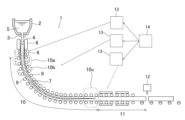
- the cooling densities X and Y of the cooling water in the bending section 10 and the horizontal section 11 are set so as to prevent surface cracks from occurring in the slab 7 when it is bent or straightened in the upper straightening band 10a or the lower straightening band 10c. That is, if the surface temperature of the slab 7 in the upper straightening band 10a or the lower straightening band 10c is within the embrittlement temperature range of the slab 7, surface cracks may occur in the slab 7 when it is bent or straightened.
Landscapes
- Engineering & Computer Science (AREA)
- Mechanical Engineering (AREA)
- Continuous Casting (AREA)
Abstract
Description
[1]鋳型と、鋳型から引き抜かれた鋳片の移動方向で前記鋳型の下流側に配置された垂直部と、前記移動方向で前記垂直部の下流側に配置された曲げ部と、前記移動方向で前記曲げ部の下流側に配置された水平部と、を備えている連続鋳造機による鋳片の連続鋳造方法であって、前記垂直部の出側の前記鋳片の表面温度が700℃以上1200℃以下であり、前記曲げ部での冷却水量から算出される第1冷却密度Xが前記水平部での冷却水量から算出される第2冷却密度Y以下である、鋳片の連続鋳造方法。
[2]前記垂直部、前記曲げ部、および、前記水平部のそれぞれで、前記鋳片に対して冷却水を供給するように構成されており、前記第1冷却密度Xは、前記曲げ部内で前記鋳片に供給される冷却水の総供給量を当該曲げ部内の前記鋳片の表面積によって除算した値であり、前記第2冷却密度Yは、前記水平部内で前記鋳片に供給される冷却水の総供給量を当該水平部内の前記鋳片の表面積によって除算した値である、[1]に記載の鋳片の連続鋳造方法。
[3]前記鋳片の厚みが350mm以上500mm以下である、[1]または[2]に記載の鋳片の連続鋳造方法。
[4]前記垂直部での前記鋳片の引き抜き速度が0.2~1.5m/minである、[1]から[3]のいずれかに記載の鋳片の連続鋳造方法。
本実施形態の作用・効果について説明する。鋳型6から350~500mmの厚みの鋳片7が引き抜かれる。当該鋳片7の引き抜き速度は0.2~1.5m/minに設定されている。その鋳片7には、垂直部8において、スプレーノズルから冷却水が吹き付けられる。こうして予め設定した温度にまで表面温度が低下させられる。本実施形態では、垂直部8の出側の鋳片7の表面温度は700~1200℃であることが好ましい。例えば、垂直部8の出側の鋳片7の表面温度が700℃未満であると、上部矯正帯10aや下部矯正帯10cを通過するときに、鋳片7の表面温度が脆化温度域に入ってしまい、鋳片7の表面割れが生じる可能性がある。一方、垂直部8の出側の鋳片7の表面温度が1200℃を超えると、バルジング増大により引き抜き不良が発生する可能性がある。

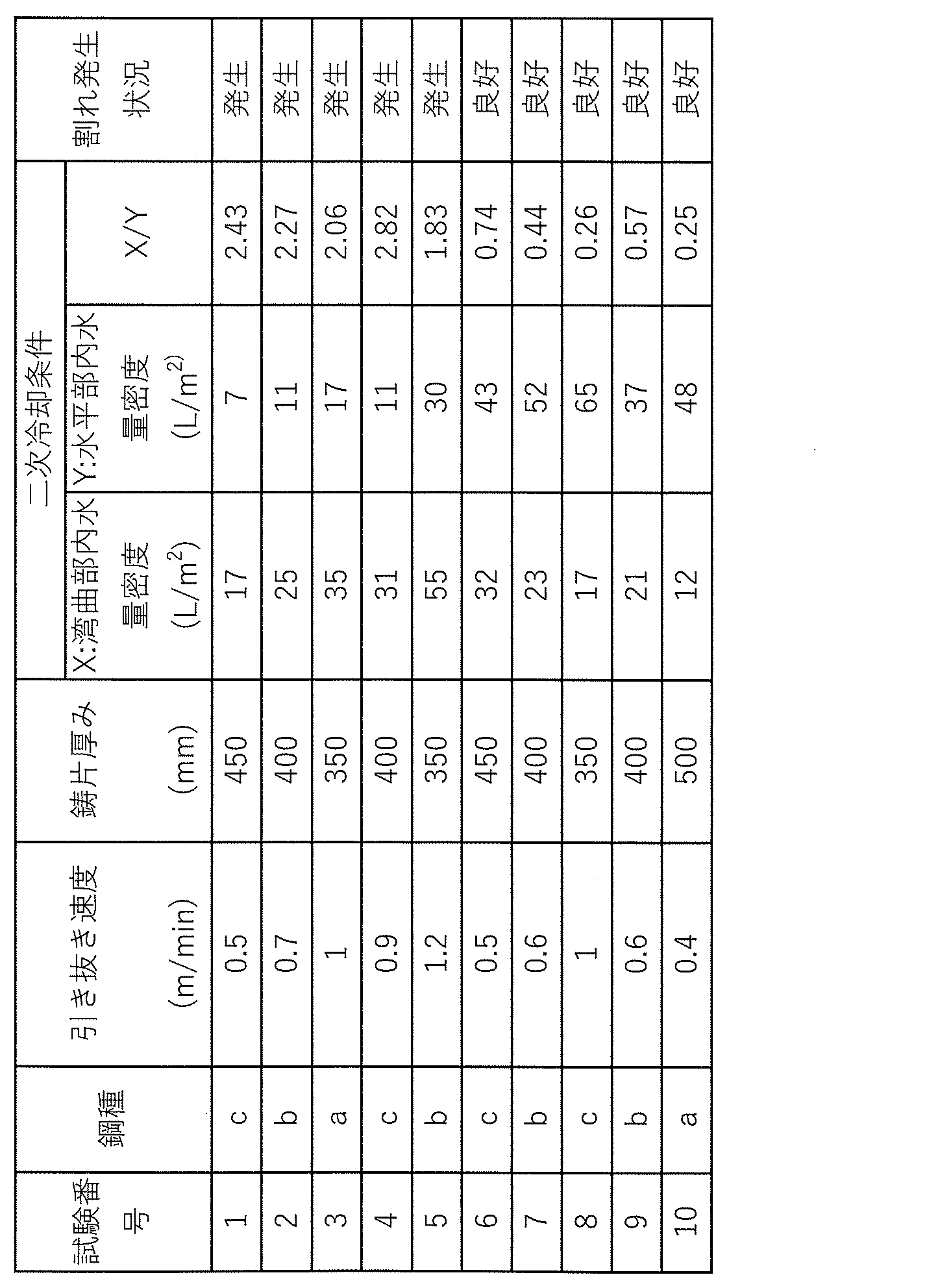
表面割れのチェック方法について説明する。表2に示す条件で製造した鋳片の両面のそれぞれについて、約2mm切削した。その後、切削後の鋳片の各面の表面割れを浸透探傷試験(カラーチェックと称されることがある。)によって検出した。そして、鋳片の各面の表面割れの個数をカウントし、表面割れの合計個数が3個以下の場合に、当該鋳片について、「割れ良好」つまり、表面割れが従来よりも抑制されていると評価した。また、表面割れの合計個数が3個を超える場合に、当該鋳片について、「割れ発生」つまり、表面割れが従来とほぼ同等であると評価した。それらの評価結果を上述した製造条件と合わせて表2にまとめて示してある。表2に示す試験番号1~5は、各種の製造条件が本発明で規定する範囲を外れる比較例である。試験番号6~10は、各種の製造条件が本発明で規定する範囲内にある実施例である。
表2に示すように、比較例である試験番号1~5の条件で製造された鋳片は「割れ発生」と評価された。実施例である試験番号6~10の条件で製造された鋳片は「割れ良好」と評価された。したがって、本発明に係る鋳片の連続鋳造法を実施することにより、従来になく厚みのある鋳片を従来になく高速で製造する場合に、鋳片の表面割れの発生を防止もしくは抑制できることが確認された。
2 タンディッシュ
3 スライディングノズル
4 浸漬ノズル
5 溶鋼
6 鋳型
7 鋳片
8 垂直部
9 鋳片支持ロール
10 曲げ部
10a 第1セグメント、上部矯正帯
10b 第2セグメント
10c 最終セグメント、下部矯正帯
11 水平部
12 鋳片切断機
13 流量制御装置
14 冷却水の供給源
Claims (5)
- 鋳型と、鋳型から引き抜かれた鋳片の移動方向で前記鋳型の下流側に配置された垂直部と、前記移動方向で前記垂直部の下流側に配置された曲げ部と、前記移動方向で前記曲げ部の下流側に配置された水平部と、を備えている連続鋳造機による鋳片の連続鋳造方法であって、
前記垂直部の出側の前記鋳片の表面温度が700℃以上1200℃以下であり、
前記曲げ部での冷却水量から算出される第1冷却密度Xが前記水平部での冷却水量から算出される第2冷却密度Y以下である、鋳片の連続鋳造方法。 - 前記垂直部、前記曲げ部、および、前記水平部のそれぞれで、前記鋳片に対して冷却水を供給するように構成されており、
前記第1冷却密度Xは、前記曲げ部内で前記鋳片に供給される冷却水の総供給量を当該曲げ部内の前記鋳片の表面積によって除算した値であり、
前記第2冷却密度Yは、前記水平部内で前記鋳片に供給される冷却水の総供給量を当該水平部内の前記鋳片の表面積によって除算した値である、請求項1に記載の鋳片の連続鋳造方法。 - 前記鋳片の厚みが350mm以上500mm以下である、請求項1または2に記載の鋳片の連続鋳造方法。
- 前記垂直部での前記鋳片の引き抜き速度が0.2~1.5m/minである、請求項1または2に記載の鋳片の連続鋳造方法。
- 前記垂直部での前記鋳片の引き抜き速度が0.2~1.5m/minである、請求項3に記載の鋳片の連続鋳造方法。
Priority Applications (4)
| Application Number | Priority Date | Filing Date | Title |
|---|---|---|---|
| CN202480080469.2A CN122497558A (zh) | 2023-12-26 | 2024-09-17 | 铸片的连续铸造方法 |
| JP2024572378A JP7831652B2 (ja) | 2023-12-26 | 2024-09-17 | 鋳片の連続鋳造方法 |
| KR1020267019911A KR20260116005A (ko) | 2023-12-26 | 2024-09-17 | 주편의 연속 주조 방법 |
| EP24911875.3A EP4782125A1 (en) | 2023-12-26 | 2024-09-17 | Continuous casting method for cast slab |
Applications Claiming Priority (2)
| Application Number | Priority Date | Filing Date | Title |
|---|---|---|---|
| JP2023218734 | 2023-12-26 | ||
| JP2023-218734 | 2023-12-26 |
Publications (1)
| Publication Number | Publication Date |
|---|---|
| WO2025141981A1 true WO2025141981A1 (ja) | 2025-07-03 |
Family
ID=96217291
Family Applications (1)
| Application Number | Title | Priority Date | Filing Date |
|---|---|---|---|
| PCT/JP2024/033020 Pending WO2025141981A1 (ja) | 2023-12-26 | 2024-09-17 | 鋳片の連続鋳造方法 |
Country Status (6)
| Country | Link |
|---|---|
| EP (1) | EP4782125A1 (ja) |
| JP (1) | JP7831652B2 (ja) |
| KR (1) | KR20260116005A (ja) |
| CN (1) | CN122497558A (ja) |
| TW (1) | TW202525455A (ja) |
| WO (1) | WO2025141981A1 (ja) |
Citations (7)
| Publication number | Priority date | Publication date | Assignee | Title |
|---|---|---|---|---|
| JP2006130547A (ja) * | 2004-11-09 | 2006-05-25 | Jfe Steel Kk | 中炭素鋼の連続鋳造方法 |
| JP2007229736A (ja) | 2006-02-28 | 2007-09-13 | Nippon Steel Corp | 厚鋼板用大断面鋳片の垂直型連続鋳造方法 |
| JP2009274116A (ja) | 2008-05-15 | 2009-11-26 | Kobe Steel Ltd | 垂直曲げ型の連続鋳造機 |
| JP2011218403A (ja) * | 2010-04-09 | 2011-11-04 | Nippon Steel Corp | 鋼の連続鋳造方法 |
| JP2014061527A (ja) * | 2012-09-20 | 2014-04-10 | Jfe Steel Corp | 連続鋳造鋳片の2次冷却方法 |
| JP2019141865A (ja) * | 2018-02-19 | 2019-08-29 | 日本製鉄株式会社 | 鋼の連続鋳造方法 |
| JP2019155419A (ja) * | 2018-03-13 | 2019-09-19 | 日本製鉄株式会社 | 鋳片の連続鋳造方法 |
-
2024
- 2024-09-17 CN CN202480080469.2A patent/CN122497558A/zh active Pending
- 2024-09-17 WO PCT/JP2024/033020 patent/WO2025141981A1/ja active Pending
- 2024-09-17 KR KR1020267019911A patent/KR20260116005A/ko active Pending
- 2024-09-17 JP JP2024572378A patent/JP7831652B2/ja active Active
- 2024-09-17 EP EP24911875.3A patent/EP4782125A1/en active Pending
- 2024-09-24 TW TW113136190A patent/TW202525455A/zh unknown
Patent Citations (7)
| Publication number | Priority date | Publication date | Assignee | Title |
|---|---|---|---|---|
| JP2006130547A (ja) * | 2004-11-09 | 2006-05-25 | Jfe Steel Kk | 中炭素鋼の連続鋳造方法 |
| JP2007229736A (ja) | 2006-02-28 | 2007-09-13 | Nippon Steel Corp | 厚鋼板用大断面鋳片の垂直型連続鋳造方法 |
| JP2009274116A (ja) | 2008-05-15 | 2009-11-26 | Kobe Steel Ltd | 垂直曲げ型の連続鋳造機 |
| JP2011218403A (ja) * | 2010-04-09 | 2011-11-04 | Nippon Steel Corp | 鋼の連続鋳造方法 |
| JP2014061527A (ja) * | 2012-09-20 | 2014-04-10 | Jfe Steel Corp | 連続鋳造鋳片の2次冷却方法 |
| JP2019141865A (ja) * | 2018-02-19 | 2019-08-29 | 日本製鉄株式会社 | 鋼の連続鋳造方法 |
| JP2019155419A (ja) * | 2018-03-13 | 2019-09-19 | 日本製鉄株式会社 | 鋳片の連続鋳造方法 |
Also Published As
| Publication number | Publication date |
|---|---|
| CN122497558A (zh) | 2026-07-31 |
| EP4782125A1 (en) | 2026-07-29 |
| KR20260116005A (ko) | 2026-07-27 |
| TW202525455A (zh) | 2025-07-01 |
| JP7831652B2 (ja) | 2026-03-17 |
| JPWO2025141981A1 (ja) | 2025-07-03 |
Similar Documents
| Publication | Publication Date | Title |
|---|---|---|
| JP6384679B2 (ja) | 熱延鋼板の製造方法 | |
| CN110666125B (zh) | 连铸坯翘头消除方法 | |
| KR102638366B1 (ko) | 연속 주조 주편의 2 차 냉각 방법 및 장치 | |
| JP5604946B2 (ja) | 鋼の連続鋳造方法 | |
| CN113927008A (zh) | 一种抑制板坯生产双相钢结晶器液面周期性波动的生产方法 | |
| JP4948225B2 (ja) | 連続鋳造2次冷却比水量のストランド別制御による健全な内部組織を有する鋳片の製造方法 | |
| JP3427794B2 (ja) | 連続鋳造方法 | |
| JP2005279691A (ja) | 連続鋳造鋳片の二次冷却方法 | |
| JP4786473B2 (ja) | 表内質に優れた鋳片の製造方法 | |
| JP5505056B2 (ja) | 金属の連続鋳造方法 | |
| JP5825087B2 (ja) | 連続鋳造方法 | |
| JP7831652B2 (ja) | 鋳片の連続鋳造方法 | |
| JP5094154B2 (ja) | 連続鋳造機における鋳片冷却方法 | |
| JP3526705B2 (ja) | 高炭素鋼の連続鋳造方法 | |
| KR101360660B1 (ko) | 에지 품질이 우수한 오스테나이트계 스테인리스 강판의 제조방법 | |
| JP7355285B1 (ja) | 鋼の連続鋳造方法 | |
| JP4626384B2 (ja) | スラブ連続鋳造における鋳片の二次冷却方法 | |
| JPH05200514A (ja) | 連続鋳造方法 | |
| JPH0390263A (ja) | 連続鋳造方法 | |
| JP3994852B2 (ja) | 垂直曲げ型連続鋳造機による連続鋳造方法およびそれにより製造される鋳片 | |
| WO2021175242A1 (en) | Boron-added steel and production method thereof | |
| JP2006181583A (ja) | 連続鋳造鋳片の製造方法 | |
| JP3356091B2 (ja) | 薄鋳片の連続鋳造方法 | |
| JP4684204B2 (ja) | 連続鋳造の終了方法 | |
| JP7502604B2 (ja) | 連続鋳造方法及び連続鋳造機 |
Legal Events
| Date | Code | Title | Description |
|---|---|---|---|
| ENP | Entry into the national phase |
Ref document number: 2024572378 Country of ref document: JP Kind code of ref document: A |
|
| WWE | Wipo information: entry into national phase |
Ref document number: 2024572378 Country of ref document: JP |
|
| 121 | Ep: the epo has been informed by wipo that ep was designated in this application |
Ref document number: 24911875 Country of ref document: EP Kind code of ref document: A1 |
|
| ENP | Entry into the national phase |
Ref document number: 1020267019911 Country of ref document: KR Free format text: ST27 STATUS EVENT CODE: A-0-1-A10-A15-NAP-PA0105 (AS PROVIDED BY THE NATIONAL OFFICE) |
|
| WWE | Wipo information: entry into national phase |
Ref document number: 1020267019911 Country of ref document: KR |
|
| REG | Reference to national code |
Ref country code: BR Ref legal event code: B01A Ref document number: 112026015137 Country of ref document: BR |
|
| WWP | Wipo information: published in national office |
Ref document number: 1020267019911 Country of ref document: KR |