WO2025136558A1 - Method for processing conductive polymer binder for electrochemical devices - Google Patents
Method for processing conductive polymer binder for electrochemical devices Download PDFInfo
- Publication number
- WO2025136558A1 WO2025136558A1 PCT/US2024/056284 US2024056284W WO2025136558A1 WO 2025136558 A1 WO2025136558 A1 WO 2025136558A1 US 2024056284 W US2024056284 W US 2024056284W WO 2025136558 A1 WO2025136558 A1 WO 2025136558A1
- Authority
- WO
- WIPO (PCT)
- Prior art keywords
- chain
- conductive polymer
- polymer
- independently
- pfo
- Prior art date
- Legal status (The legal status is an assumption and is not a legal conclusion. Google has not performed a legal analysis and makes no representation as to the accuracy of the status listed.)
- Pending
Links
Classifications
-
- H—ELECTRICITY
- H01—ELECTRIC ELEMENTS
- H01B—CABLES; CONDUCTORS; INSULATORS; SELECTION OF MATERIALS FOR THEIR CONDUCTIVE, INSULATING OR DIELECTRIC PROPERTIES
- H01B1/00—Conductors or conductive bodies characterised by the conductive materials; Selection of materials as conductors
- H01B1/06—Conductors or conductive bodies characterised by the conductive materials; Selection of materials as conductors mainly consisting of other non-metallic substances
- H01B1/12—Conductors or conductive bodies characterised by the conductive materials; Selection of materials as conductors mainly consisting of other non-metallic substances organic substances
- H01B1/124—Intrinsically conductive polymers
- H01B1/128—Intrinsically conductive polymers comprising six-membered aromatic rings in the main chain, e.g. polyanilines, polyphenylenes
-
- C—CHEMISTRY; METALLURGY
- C08—ORGANIC MACROMOLECULAR COMPOUNDS; THEIR PREPARATION OR CHEMICAL WORKING-UP; COMPOSITIONS BASED THEREON
- C08G—MACROMOLECULAR COMPOUNDS OBTAINED OTHERWISE THAN BY REACTIONS ONLY INVOLVING UNSATURATED CARBON-TO-CARBON BONDS
- C08G61/00—Macromolecular compounds obtained by reactions forming a carbon-to-carbon link in the main chain of the macromolecule
- C08G61/12—Macromolecular compounds containing atoms other than carbon in the main chain of the macromolecule
-
- C—CHEMISTRY; METALLURGY
- C08—ORGANIC MACROMOLECULAR COMPOUNDS; THEIR PREPARATION OR CHEMICAL WORKING-UP; COMPOSITIONS BASED THEREON
- C08L—COMPOSITIONS OF MACROMOLECULAR COMPOUNDS
- C08L65/00—Compositions of macromolecular compounds obtained by reactions forming a carbon-to-carbon link in the main chain; Compositions of derivatives of such polymers
-
- C—CHEMISTRY; METALLURGY
- C09—DYES; PAINTS; POLISHES; NATURAL RESINS; ADHESIVES; COMPOSITIONS NOT OTHERWISE PROVIDED FOR; APPLICATIONS OF MATERIALS NOT OTHERWISE PROVIDED FOR
- C09D—COATING COMPOSITIONS, e.g. PAINTS, VARNISHES OR LACQUERS; FILLING PASTES; CHEMICAL PAINT OR INK REMOVERS; INKS; CORRECTING FLUIDS; WOODSTAINS; PASTES OR SOLIDS FOR COLOURING OR PRINTING; USE OF MATERIALS THEREFOR
- C09D165/00—Coating compositions based on macromolecular compounds obtained by reactions forming a carbon-to-carbon link in the main chain; Coating compositions based on derivatives of such polymers
-
- C—CHEMISTRY; METALLURGY
- C09—DYES; PAINTS; POLISHES; NATURAL RESINS; ADHESIVES; COMPOSITIONS NOT OTHERWISE PROVIDED FOR; APPLICATIONS OF MATERIALS NOT OTHERWISE PROVIDED FOR
- C09D—COATING COMPOSITIONS, e.g. PAINTS, VARNISHES OR LACQUERS; FILLING PASTES; CHEMICAL PAINT OR INK REMOVERS; INKS; CORRECTING FLUIDS; WOODSTAINS; PASTES OR SOLIDS FOR COLOURING OR PRINTING; USE OF MATERIALS THEREFOR
- C09D5/00—Coating compositions, e.g. paints, varnishes or lacquers, characterised by their physical nature or the effects produced; Filling pastes
- C09D5/24—Electrically-conducting paints
-
- C—CHEMISTRY; METALLURGY
- C09—DYES; PAINTS; POLISHES; NATURAL RESINS; ADHESIVES; COMPOSITIONS NOT OTHERWISE PROVIDED FOR; APPLICATIONS OF MATERIALS NOT OTHERWISE PROVIDED FOR
- C09D—COATING COMPOSITIONS, e.g. PAINTS, VARNISHES OR LACQUERS; FILLING PASTES; CHEMICAL PAINT OR INK REMOVERS; INKS; CORRECTING FLUIDS; WOODSTAINS; PASTES OR SOLIDS FOR COLOURING OR PRINTING; USE OF MATERIALS THEREFOR
- C09D7/00—Features of coating compositions, not provided for in group C09D5/00; Processes for incorporating ingredients in coating compositions
- C09D7/40—Additives
- C09D7/65—Additives macromolecular
-
- H—ELECTRICITY
- H01—ELECTRIC ELEMENTS
- H01B—CABLES; CONDUCTORS; INSULATORS; SELECTION OF MATERIALS FOR THEIR CONDUCTIVE, INSULATING OR DIELECTRIC PROPERTIES
- H01B1/00—Conductors or conductive bodies characterised by the conductive materials; Selection of materials as conductors
- H01B1/06—Conductors or conductive bodies characterised by the conductive materials; Selection of materials as conductors mainly consisting of other non-metallic substances
- H01B1/12—Conductors or conductive bodies characterised by the conductive materials; Selection of materials as conductors mainly consisting of other non-metallic substances organic substances
- H01B1/124—Intrinsically conductive polymers
- H01B1/127—Intrinsically conductive polymers comprising five-membered aromatic rings in the main chain, e.g. polypyrroles, polythiophenes
-
- C—CHEMISTRY; METALLURGY
- C08—ORGANIC MACROMOLECULAR COMPOUNDS; THEIR PREPARATION OR CHEMICAL WORKING-UP; COMPOSITIONS BASED THEREON
- C08G—MACROMOLECULAR COMPOUNDS OBTAINED OTHERWISE THAN BY REACTIONS ONLY INVOLVING UNSATURATED CARBON-TO-CARBON BONDS
- C08G2261/00—Macromolecular compounds obtained by reactions forming a carbon-to-carbon link in the main chain of the macromolecule
- C08G2261/10—Definition of the polymer structure
- C08G2261/11—Homopolymers
-
- C—CHEMISTRY; METALLURGY
- C08—ORGANIC MACROMOLECULAR COMPOUNDS; THEIR PREPARATION OR CHEMICAL WORKING-UP; COMPOSITIONS BASED THEREON
- C08G—MACROMOLECULAR COMPOUNDS OBTAINED OTHERWISE THAN BY REACTIONS ONLY INVOLVING UNSATURATED CARBON-TO-CARBON BONDS
- C08G2261/00—Macromolecular compounds obtained by reactions forming a carbon-to-carbon link in the main chain of the macromolecule
- C08G2261/10—Definition of the polymer structure
- C08G2261/14—Side-groups
- C08G2261/142—Side-chains containing oxygen
- C08G2261/1424—Side-chains containing oxygen containing ether groups, including alkoxy
-
- C—CHEMISTRY; METALLURGY
- C08—ORGANIC MACROMOLECULAR COMPOUNDS; THEIR PREPARATION OR CHEMICAL WORKING-UP; COMPOSITIONS BASED THEREON
- C08G—MACROMOLECULAR COMPOUNDS OBTAINED OTHERWISE THAN BY REACTIONS ONLY INVOLVING UNSATURATED CARBON-TO-CARBON BONDS
- C08G2261/00—Macromolecular compounds obtained by reactions forming a carbon-to-carbon link in the main chain of the macromolecule
- C08G2261/30—Monomer units or repeat units incorporating structural elements in the main chain
- C08G2261/31—Monomer units or repeat units incorporating structural elements in the main chain incorporating aromatic structural elements in the main chain
- C08G2261/314—Condensed aromatic systems, e.g. perylene, anthracene or pyrene
- C08G2261/3142—Condensed aromatic systems, e.g. perylene, anthracene or pyrene fluorene-based, e.g. fluorene, indenofluorene, or spirobifluorene
-
- C—CHEMISTRY; METALLURGY
- C08—ORGANIC MACROMOLECULAR COMPOUNDS; THEIR PREPARATION OR CHEMICAL WORKING-UP; COMPOSITIONS BASED THEREON
- C08G—MACROMOLECULAR COMPOUNDS OBTAINED OTHERWISE THAN BY REACTIONS ONLY INVOLVING UNSATURATED CARBON-TO-CARBON BONDS
- C08G2261/00—Macromolecular compounds obtained by reactions forming a carbon-to-carbon link in the main chain of the macromolecule
- C08G2261/40—Polymerisation processes
- C08G2261/41—Organometallic coupling reactions
- C08G2261/412—Yamamoto reactions
-
- C—CHEMISTRY; METALLURGY
- C08—ORGANIC MACROMOLECULAR COMPOUNDS; THEIR PREPARATION OR CHEMICAL WORKING-UP; COMPOSITIONS BASED THEREON
- C08G—MACROMOLECULAR COMPOUNDS OBTAINED OTHERWISE THAN BY REACTIONS ONLY INVOLVING UNSATURATED CARBON-TO-CARBON BONDS
- C08G2261/00—Macromolecular compounds obtained by reactions forming a carbon-to-carbon link in the main chain of the macromolecule
- C08G2261/40—Polymerisation processes
- C08G2261/41—Organometallic coupling reactions
- C08G2261/416—Organometallic coupling reactions zinc-based, e.g. Rieke reactions
-
- H—ELECTRICITY
- H10—SEMICONDUCTOR DEVICES; ELECTRIC SOLID-STATE DEVICES NOT OTHERWISE PROVIDED FOR
- H10K—ORGANIC ELECTRIC SOLID-STATE DEVICES
- H10K30/00—Organic devices sensitive to infrared radiation, light, electromagnetic radiation of shorter wavelength or corpuscular radiation
- H10K30/80—Constructional details
- H10K30/81—Electrodes
-
- H—ELECTRICITY
- H10—SEMICONDUCTOR DEVICES; ELECTRIC SOLID-STATE DEVICES NOT OTHERWISE PROVIDED FOR
- H10K—ORGANIC ELECTRIC SOLID-STATE DEVICES
- H10K85/00—Organic materials used in the body or electrodes of devices covered by this subclass
- H10K85/20—Carbon compounds, e.g. carbon nanotubes or fullerenes
Definitions
- the conductive polymer is a poly(9,9- dioctylfluorene-co-fluorenone-co-methylbenzoic ester) (PFM), and a PFM heated or thermally treated by the method of the present invention is a HOS-PFM.
- PFM poly(9,9- dioctylfluorene-co-fluorenone-co-methylbenzoic ester)
- HOS-PFM a poly(9,9- dioctylfluorene-co-fluorenone-co-methylbenzoic ester)
- HOS-PFM a PFM heated or thermally treated by the method of the present invention
- the electrically conductive polymer or conductive polymer is heated or thermally treated, one or more side chains are decomposed or removed.
- the HOS-electrically conductive polymer or HOS-conductive polymer have a higher ordered structure.
- the method can be used to apply or coat the binder/electrically conductive polymer-conductive material composite on a surface of an electrode, such as a cathode or anode of a device, such as a battery.
- the conductive material is a silicon oxide (SiOx), Si-C, Si, or Si-graphite. In some embodiments, the conductive material is in particle form. In some embodiments, the method results in the electrically conductive polymer coating the conductive material, such as the conductive material in particle form.
- the electrically conductive polymer, or one or more monomer units of the polymer comprises one or more chains, wherein each chain comprises one or more ether, methoxy and/or ethoxy groups, wherein there are sufficient ether, methoxy and/or ethoxy groups thereby the electrically conductive polymer is soluble in the alcohol-water solvent or water.
- the electrically conductive polymer to a surface comprising: (a) providing an electrically conductive polymer having the following chemical structure: —
- R 1 and R 2 are each independently an alkyl chain or oligo ethyleoxide chain or alkyloxide chain of any length between 1-10000 carbon atoms;
- G and G 1 are each independently — H, — F, — COOCH 3 , — COOH, or — SO 3 CH 3 ;
- n + m + q 1, and representing the relative abundance in the polymer chain;
- n, m, and q are each independently any number between 0-1; and,
- R 1 and R 2 are each independently hydroxide terminated or carboxylic acid or carboxylate salt terminated; — Q n — Q’ m — (II); wherein Q and Q’ are each independently is one of the following chemical structures:
- n is between 1 and 100M;
- R 1 and R 2 are each independently an alkyl chain or oligo ethyleoxide chain or alkyloxide chain of any length between 1-10000 carbon atoms; and R 1 and/or R 2 can be hydroxide terminated or carboxylic acid or carboxylate salt terminated;
- (III) is — COO — , — O — , — NH — , — S — , or a covalent bond;
- Z is — H or — CH 3 ; or,
- the electrically conductive polymer has the following chemical structure: q I a ) or
- the at least one of E and F is are each
- the electrically conductive polymer has the following chemical
- the electrically conductive polymer has the chemical structure of (X) n (V), wherein conductive polymer has the following chemical structure:
- R 1 , R 2 , R 3 , R 4 , R 5 , R 6 , R 7 , R 8 , R 9 , R 10 , R 11 , R 12 , R 13 , R 14 , and Ris are each independently an alkyl chain or oligo ethyleoxide chain or alkyloxide chain of any length between 1-10000 carbon atoms.
- each side chain is independently any length between 1-1000 carbon atoms.
- each side chain is independently any length between 1-100 carbon atoms.
- each side chain independently comprises 1, 2, 3, 4, 5, 6, 7, 8, 9, or 10 carbon atoms.
- the method further comprises heating the alcohol and the polymer to about or at least about 50 °C, 60 °C, 70 °C, 80 °C, 90 °C, or 100 °C, or a temperature within a range of any two preceding values, to dissolve the polymer in the alcohol.
- any or all of the polymer, conductive material, alcohol, water, or surface is pre-heated to a temperature prior to any of the introducing or applying step.
- the alcohol is an organic compound having 1, 2, 3, 4, 5, 6, 7, 8, 9, or 10, or a number within a range of any two preceding numbers, carbon atoms. In some embodiments, the alcohol is straight chained or branched. In some embodiments, the alcohol is an organic compound having 1, 2, 3, 4, 5, 6, 7, 8, 9, or 10, or a number within a range of any two preceding numbers, hydroxyl function group. In some embodiments, the alcohol is methanol, ethanol, 1-propanol, 2- propanol, or isopropanol.
- the alcohol and water have a ratio to each other about 1 :9, 2:8, 3:7, 4:6, 5:5, 6:4, 7:3, 8:2, or 9: 1, or a ratio within a range of any two preceding values, by weight, by volume, or by mole.
- the heating step (g) comprises heating to a temperature of about or at least about 200 °C, 300 °C, 400 °C, 500 °C, 600 °C, or 700 °C, or a temperature within a range of any two preceding values.
- the present invention provides for a composition comprising the electrically conductive polymer and an alcohol and water.
- the composition is a solution wherein the electrically conductive polymer is dissolved in the alcohol and water.
- the composition is a slurry further comprising a silicon oxide.
- the composition further comprising one or more active material and/or additive particles.
- the present invention provides for a device comprising a current collector applied or coated with the composition of the present invention.
- the composition is dried on the current collector.
- the dried composition is a film, such as a laminate film, such as a composite laminate film.
- the method is used to construct 2 Ah pouch cell development based on PFO binder and SiO negative electrode.
- the binders and processes are intended to be used in making high energy density lithium-ion batteries.
- the class of binders is made at lower cost compare to the regular PFM conductive polymer binder.
- the PFO binder is soluble in an alcohol, such as ethanol, and water, so can be processing in an environmentally friendly slurry process.
- the present invention provides for a low-cost conductive polymer binder enabled environmentally friendly processing of Si based electrode
- n has a value from 1 to 100,000,000;
- the providing step comprises heating the composition or conductive polymer such that the conductive polymer is converted into a final form.
- the final form of the conductive polymer forms a coating and/or protective layer.
- the final form of the conductive polymer forms a coating and/or protective layer covering the active materials particles.
- chemical structure (II) comprises one of chemical structures described in Figure 5 or Figure 6 of PCT International Patent Application No. PCT/US2022/12376.
- the conductive polymer has the following chemical structure: (Illa) (also referred to as “the third generic structure”); wherein R is an alkyl chain or oligo ethyleoxide chain or alkyloxide chain of any length between 1-10000 carbon atoms. In some embodiments, R can be hydroxide terminated or carboxylic acid or carboxylate salt terminated.
- chemical structure (III) comprises random copolymer(s) or block copolymer(s).
- the device comprises a lithium ion anode applications
- a conductive polymer comprises an n-type of backbone structure.
- Such conductive polymer include: side chains substituted PPV, side chains substituted polyfluorene, and/or side chains substituted polyphenylene. See Figure 9 of PCT International Patent Application No. PCT/US2022/12376.
- the conductive polymer has the following chemical structure:
- A is O, N, or S.
- R 1 is
- chemical structure (IVa) to (IVd) comprises random copolymer(s) or block copolymer(s).
- the conductive polymer has a chemical structure, and active material and/or additive particles, described in U.S. Patent Nos. 7,960,037 (Liu et al.);
- the conductive polymer has the following chemical structure: (X) n ; wherein X may be a conjugated homo polymer, a conjugated copolymer, or a linear polymer with conducting conjugated pending group.
- the conductive polymer has the following chemical structure: [0055] In some embodiments, the conductive polymer has the following chemical structure:
- R 5 and R 6 are each independently H, COOH, or COOCH 3 .
- the number of -COOH groups can be controlled without changing the electronic properties of the conductive binders.
- R 5 and R 6 are each independently H, COOH, or COOCH 3 .
- the “x, x’” unit are each independently fluorene with either alkyl or alkylcarboxylic acid at the 9, 9’positions.
- the “y” unit is fluorenone.
- the H positions of the back bone of fluorenone and fluorene are each independently substituted with one or more of the following functional groups: COOH, F, Cl, Br, SO 3 H, or the like groups.
- the oligoether groups are selected from the group consisting of methyleneoxide, ethyleneoxide, trimethyleneoxide and tetramethyleneoxide.
- the present invention provides for a method for enhancing the cycle life of recycled a graphite material from spent lithium-ion devices or batteries via the conductive polymer of the present invention.
- the conductive polymer is a coating.
- the present invention provides for a method for the regeneration and reuse of spent graphite anode materials.
- the method purifies and revitalizes graphite particles by removing legacy solid electrolyte interphase (SEI) and constructing an artificial conductive polymer-based SEI layer, known as HOS-PFM.
- SEI solid electrolyte interphase
- HOS-PFM artificial conductive polymer-based SEI layer
- This polymer has a conjugated polyfluorene backbone that significantly improves the electrical conductivity and mechanical durability of the regenerated graphite particles.
- Electrochemical tests involving both half- cells and full cells reveal that regenerated graphite coated with HOS-PFM have a remarkable increase in cycle life and demonstrate the ability to sustain high C-rate charging and discharging.
- This method provides a simple and effective solution for reclaiming and reusing graphite anodes in battery manufacturing.
- Figure 1 The molecular weight distribution of the produced PFO polymers.
- Figure 2. A) The appearance of 6.7% PFO dissolved in ethanol/water 2:1 mixture at 80 °C, cooled to about 50 °C, and cooled to 25 °C.
- FIG. 3 (A) SEM image of SiOx-PFO-400 (processed at 400 o C) fabricated from chlorobenzene. The initial weight fraction of PFO is 33%. After thermal treatment, the weight percentage decreased to 19.8%. (B) SEM image of SiOx-PFO-400 fabricated from EtOH/H2O. The initial weight fraction of PFO is 33%. After thermal treatment, the weight percentage decreased to 19.8%. [0075] Figure 4. A) The capacity evolution and B) Coulombic efficiency evolution of the SiOx-PFO electrode fabricated from chlorobenzene, with different thermal processing temperature.
- SiOx-PFO half cells were assembled and the areal capacity was around 1.5 mAh/cm 2 .
- Figure 5. The capacity evolution of the SiOx-PFO-400 electrodes fabricated from different solvents. Electrodes were processed at 400 o C. Li
- FIG. 1 The SEM image of SiOx-PFO-400 after 100 cycles.
- Figure 9. A) The evolution of Small-angle X-ray scattering (SAXS) pattern of PFO dissolved in EtOH/H 2 O (10wt%) upon heating. B) The XRD pattern of the freestanding PFO film prepared from chlorobenzene (CB) and EtOH/H 2 O mixture. C) The Wide-angle X-ray scattering (WAXS) pattern of PFO prepared from different solvents.
- D, F The morphology of PFO dried on silicon wafer, PFO sample was dissolved in NMP and EtOH/H 2 O, respectively.
- FIG. 10 A) SEM image of SiOx-PFO-400 fabricated from Chlorobenzene. the initial weight fraction of PFO is 33%. After thermal treatment, the w% decreased to 19.8%. B) SEM image of SiOx-PFO-400 fabricated from EtOH/H2O. the initial weight fraction of PFO is 33%. After thermal treatment, the w% decreased to 19.8%. C) The capacity evolution of the SiOx-PFO-400 electrodes. Li
- TGA thermogravimetric analysis
- Figure 14 A) The FT-IR spectra of unwashed graphite as well as regenerated graphite.
- Figure 15. A, D) SEM images of regenerated graphite under different magnification.
- reference to an "expression vector” includes a single expression vector as well as a plurality of expression vectors, either the same (e.g., the same operon) or different; reference to "cell” includes a single cell as well as a plurality of cells; and the like.
- the electrically conductive polymer is used in cell fabrication.
- the electrically conductive polymer is used in lithium metal electrode or anode-less electrode fabrication.
- the electrically conductive polymer is used in cell fabrication.
- the device is a Li/PFM500/Au solid-state device.
- the device comprises an Au electrode side, a middle round disk that is the gold electrode/substrate, where PFM500 is coated on the opposite side, a plastic ring, and a compressed Li metal.
- the device is a Li/PFM500/Au device.
- the device is a Na/PFM500/Au solid-state device.
- This laminate can be used in combination with liquid electrolyte, gel or solid-state electrolytes.
- the polymers can be dissolved in an alcohol water solvent and coated on to the active materials surface and dried and thermal treated at the selected temperature to transform into the final form to form the coating and protective layer.
- the coated particles can be used as battery materials.
- the polymer can be directly coated on a flat surface such as carbon, Si, Al, Li, Sn film surface and be thermal treated to transform into the final form.
- the usages can be for lithium battery, sodium battery, Mg and Zn battery system. (5) The usages are not limited to battery application, but can be used to any applications need to have ion or electron mobility.
- Electrode preparation in Chlorobenzene [00107] 100 mg PFO was first dissolved in 1.5 mL of chlorobenzene under ultrasonication for 30 minutes. Then SiOx composite (weight varies from 200 mg to 300 mg, depending on the target PFO weight fraction) was added to the solution and homogenized by continuous stirring. The obtained slurry was then coated on 50 ⁇ m-thick copper current collector with a common doctor blade coating method at room temperature. The produced electrode was dried at room temperature for 12 h and further dried by vacuum oven for 12 h. Electrode preparation in ethanol-water mixture: [00108] 100 mg PFO was first suspended in 1 mL of 200 PRF ethanol under ultrasonication for 30 minutes.
- the PFO can be dissolved in moderate concentration in ethanol solution at elevated temperature.
- the solution remains a homogenous mixture when addition of water to the PFO ethanol solution at 50 o C.
- We can also use isopropanol/water or 1-propanol/water co-solvent to dissolve PFO.
- the high boiling point water component can ensure homogeneous processing of the slurry.
- the coating of the slurry is smooth.
- the final dried laminate is uniform and defect free.
- the ratio between alcohol and water can be adjusted to achieve the best overall processing and performance.
- Electrode thermal processing [00110] SiOx-PFO film were subjected to thermal processing for formation of hierarchically ordered structures. Typically, SiOx-PFO electrodes were placed in tube furnace under argon atmosphere protection.
- Gen 2 electrolyte was also used as electrolyte and around 40 ⁇ L electrolyte was used for individual cell.
- Full cell formation was performed by cycling in between 3.0V to 4.1V at C/20 rate and C/10 rate. After that, the cell was cycled in between 3.0V to 4.1V at C/3 rate.
- EXAMPLE 2 METHODS AND MATERIALS Materials
- All chemicals for polymer synthesis were purchased and used without further purification. All materials utilized for the fabrication of the battery were procured from commercial sources. These include micro-sized SiOx particles (m-SiOx) obtained from Shin- Etsu Chemical Co., a lithium chip from MTI Co., Celgard 2400 separator from Celgard Co., a lithium-ion electrolyte consisting of 1.2 M LiPF6 in ethylene carbonate-ethyl methyl carbonate (EC:EMC) with a ratio of 3/7 w/w, specifically known as Gen 2 electrolyte and sourced from Argonne National Laboratory, and a lithium nickel manganese cobalt oxide (NCM811) cathode with a capacity of 4.0 mAh/cm 2 , produced by the CAMP Facility at Argonne National Laboratory.
- m-SiOx micro-sized SiOx particles obtained from Shin- Etsu Chemical Co.
- a lithium chip from MTI
- the purified polymer pellets were further treated by undergoing three rounds of dissolution in THF and precipitation in hexanes.
- GPC gel permeation chromatography
- Mn 11.0 kDa
- PDI 2.6.
- Doping and conductivity measurement [00116] Initially, PFO was dissolved in chlorobenzene to create a 10 wt% solution. Subsequently, 5 ⁇ L of this solution was deposited onto the interdigitated electrode and left to air-dry overnight. To eliminate any residual solvent, the interdigitated electrodes underwent a vacuum oven drying process at 80°C for 12 hours. In a two-electrode configuration, lithium foil was positioned on the anode side.
- the two pins of the interdigitated electrodes were initially short-circuited and then linked to the cathode side via copper wires.
- the polymer underwent lithiation at various potentials (from 3.00 V (OCV) to 0.01 V versus Li/Li + ).
- OCV 3.00 V
- Li/Li + 0.01 V versus Li/Li +
- the electronic conductivity at different doping states was gauged through direct current circuit measurements of the interdigitated electrode. The voltage applied ranged from 20 mV to 100 mV.
- SiOx-PFO electrode was dried at room temperature for 12 h and further dried by vacuum oven for 12 h, before being subjected to thermal processing for formation of hierarchically ordered structures.
- Electrode preparation in ethanol-water mixture [00119] 100 mg PFO was first suspended in 1 mL of 200 PRF ethanol under ultrasonication for 30 minutes. Then the suspension was heated to around 80 o C which allows complete dissolution of the PFO polymers. Subsequently, 0.5 mL of pre-heated DI water (80 o C) was added to the PFO solutions under stirring, followed by addition of SiOx composite (weight varies from 200 mg to 300 mg, depending on the target PFO weight fraction). The obtained slurry was then maintained at 80 o C, before being coated on 50 ⁇ m- thick copper current collector with a common doctor blade coating method.
- Gen 2 electrolyte (1.2 M LiPF 6 in ethylene carbonate: ethylmethyl carbonate (EC: EMC, 3:7 by weight)) was used as electrolyte. Around 40 ⁇ L electrolyte was used for individual cell. Cell formation was performed by cycling between 0.01V to 1.0V at C/10 rate for 3 times. After that, cell was cycled in between 0.05V to 1.0V. Full Cells: [00121] Pre-lithiation of SiOx-PFO anodes (HOS-PFO weight% around 16.4%) was performed by half-cell electrochemical method. CR2032 half-cells were assembled in Ar- filled glove box by sandwiching the separator (Celgard 2400) between prepared electrode and lithium metal disk.
- thermogravimetric analysis TGA of PFO under Argon atmosphere
- the thermal decomposition began from 350 o C and most of the side chains of PFO could be removed at 400 o C, corresponding to 49.5% weight retention.
- Further increasing temperature from 400 o C to 500 o C resulted in completed loss of the functionalities of PFO and the appearance of produced polymer changed from brown to black color.
- attenuated total reflectance-Fourier transform infrared spectroscopy (ATR-FTIR) analysis of the PFO samples also confirmed this stepwise decomposition. Ramping the temperature to 300 o C did not result in significant change of the spectra ( Figure 7C).
- the initial weight fraction of PFO is 33%. After thermal treatment, the w% decreased to 19.8%.
- Figure 10D shows the capacity retention of full cells cycling at a rate of 0.33C, after electrochemical pre-lithiation of the anode materials. It was found that the SiOx-PFO-400 from chlorobenzene still retained 86% capacity after 200 cycles, while SiOx-PFO-400 from EtOH/H 2 O exhibited comparable performance.
- PFO-400 °C demonstrated significant lithiation doping ability comparing to the PFO without thermal treatment, due to the formation of the higher order structure (HOS) at the molecular level. See Figure 11.
- HOS higher order structure
- Thermal treatment provided HOS-PFO as a good candidate as conjugated polymer binder.
- the decomposition temperature is controlled at 400 °C, so some side chains are still present for surface adhesion.500 °C heated sample loses all the side chains moieties, and tends to have lower adhesion, therefore worse performance.
- PFO was applied as the conductive binder for SiOx. Before thermal treatment, the weight fraction of PFO is 33%. After thermal treatment, this number ranges from 19.8% to 16.4% depending on the temperature.
- Green solvent for PFO processing SiOx-PFO-400 processed from EtOH/H 2 O demonstrated similar morphology and cycling performance to the chlorobenzene processed electrode.
- the active material is SiOx. It is also can be other types of Si materials, and tin and other alloy compounds. See Figs.3 and 5.
- Green solvent for PFO processing Full cell test results. To improve the areal capacity, the PFO was reduced to 25% (after thermal treatment at 400 °C it was 14.3%, and SiOx 85.7%) in the anode electrode.
- This polymer has a conjugated polyfluorene backbone that significantly improves the electrical conductivity and mechanical durability of the regenerated graphite particles. Electrochemical tests involving both half-cells and full cells revealed that regenerated graphite coated with HOS-PFM showed a remarkable increase in cycle life and demonstrated the ability to sustain high C-rate charging and discharging. We suggest that this method could provide a simple and effective solution for reclaiming and reusing graphite anodes in battery manufacturing. INTRODUCTION [00140] With growing concerns about climate change and global energy crisis, fuel vehicles are increasingly replaced by electrical vehicles. Consequently, as an essential component of electrical vehicles, the demand of lithium-ion batteries (LIBs) substantially increases.
- LIBs lithium-ion batteries
- the global lithium-ion batteries market value is predicted to reach $139 billion by 2029 [1].
- the production of the lithium-ion batteries and the generation of electrical waste after their lifespan can cause significant natural resource exhaustion [1, 2].
- More than 11 million tons of LIBs would be discarded between 2017 and 2030.
- Mistreatment of the spent LIBs would release pollutants such as heavy metals and toxic lithium salts to environment [1-3]. Therefore, recycling spent lithium-ion batteries become an urgent need to reduce material waste and converse resources and energy [4, 5].
- the common pyrometallurgical process for recycling cathode materials is also one of the classical methods for graphite recycling, which includes inert atmosphere roasting and graphitization, followed by ultrasonic vibration or sieving to remove the current collector residues [13, 14].
- the multiunit operation and high energy consumption raise the financial costs thus limit the application of this method [15].
- the hydrometallurgical process such as acid leaching is recognized as a graphite recycling method due to its low energy consumption and high recovery efficiency [7, 16, 17].
- lithium salts and solid electrolyte interphase (SEI) films could be extracted from anode materials.
- Jegan Roy et al. developed a bioleaching approach using the microorganism A.
- PFM poly(9,9-dioctylfluorene-co-fluorenone-co-methylbenzoic ester)
- HOS-PFM further enhances the conductivity of the retrieved graphite particles [22].
- surface treatment with polymer coating and thermal processing, we can improve the mechanical strength and conductivity of the spent graphite, and the resulting graphite materials with thin coating of HOS-PFM can be refabricated into new electrodes for batteries.
- NMP N-methyl pyrrolidone
- the polymer coating served as a protective layer of recycled graphite particles and a charge transport agent to enhance conductivity of the graphite anode material (Figure 13).
- PVDF Polyvinylidene fluoride
- CB chlorobenzene
- PFM was synthesized according to our previous report [21].
- Spent lithium-ion batteries for graphite recycling were collected from General Motors.
- Acetylene black (Denka black) was purchased from Denka Co.
- Thermogravimetric analysis (TGA) of PFM was conducted via the thermal analyzer from TA instruments under nitrogen atmosphere. The ramping rate for the TGA measurement was 5°C/min.
- Scanning Electron Microscopy (SEM) was conducted via the JEOL JSM-7500F Field Emission Scanning Electron Microscope. Elemental mapping of the electrodes was performed at Zeiss Gemini Ultra-55 Analytical Field Emission Scanning Electron Microscope coupled to a Bruker X-Ray Energy Dispersive Spectrometer (X-Ray EDS).
- the Fourier Transform Infrared (FT-IR) spectra was obtained from Thermo-Fischer Nicolet iS50 FTIR spectrometer.
- Coin cell assembly [00150] CR2032 coin cells were assembled in an argon-filled glovebox. For the half cells, the graphite electrode (14.3 mm diameter disk) and lithium chip counter electrode (16 mm diameter) were assembled in a cell with Celgard 2400 separator and 60 ⁇ L lithium-ion electrolyte. For the full cells, the graphite anode (14.3 mm diameter disk) and the cathode NMC 532 electrode (12.7 mm diameter) were assembled in a cell with Celgard 2400 separator and 60 ⁇ L lithium-ion electrolyte.
- the assembled cells were cycled at 0.1 C between 0.01-1.0 V (vs. Li/Li + ) at 30°C.
- the assembled cells were cycled at 0.04 C for three cycles, 0.1 C for two cycles, 0.2 C for two cycles, and 0.33 C for 300 cycles between 3.8-4.1 V (vs. Li/Li + ) at 30°C.
- the C-rate was calculated based on the theoretical capacity upon a full lithiation of graphite.
- the assembled cells were cycled at 0.04 C for three cycles, 0.1 C for three cycles, 0.2 C for three cycles, 0.33 C for three cycles, 1.00 C for three cycles, and 2.00 C for three cycles.
- HOS-PFM-OCV open circuit voltage
- HOS-PFM-0V the sample was reduced to 0V (vs. Li/Li + ) using linear sweep voltammetry (LSV) at a rate of 0.1 mV/s and then held at 0V for 24 hours.
- HOS-PFM-0.01V, HOS-PFM-0.05V, HOS-PFM-0.1V, HOS-PFM-0.2V, HOS-PFM-0.3V, HOS-PFM-0.4V, HOS-PFM-0.5V were prepared by modifying the target voltage for lithiation accordingly.
- the HOS-PFM samples were washed with anhydrous ethyl methyl carbonate (EMC) and digested in a solution containing 3% w/v HCl and 1% w/v HNO3 for subsequent elemental analysis. This analysis was conducted with a Perkin Elmer Inductively Coupled Plasma (ICP) Optima 7000 DV Spectrometer.
- ICP Perkin Elmer Inductively Coupled Plasma
- the outer layer containing loose organic oligomers derived from ring-opening polymerization of carbonates is primarily insulating and known as poor SEIs [24].
- HOS-PFM polymer layer surrounding the graphite particles are ionic conductive [22], and it will not block the lithium pathways towards graphite particles. This was further evidence by elemental analysis via ICP-OES ( Figure 16, Panel A). Significant quantities of lithium were detected in HOS-PFM samples after potential hold under various voltages ranging from 0V to 0.4V, whereas the amount of phosphorus was lower than the detection limit of the instrument (0.01 ppm).
- HOS-PFM-0V sample has a C/Li ratio of 0.28, and the quantities of Li were lower than the detection limit in those samples that were lithiated under voltages greater than 0.5V.
- This result aligns with the linear sweep voltammetry result of Li
- the voltage decreased from OCV to 0V, the current increases accordingly, which corresponds to the amount of lithium ion diffused into the conductive polymer. Therefore, HOS-PFM provides an electronic conductive and ionic conductive artificial SEI layer at the surface of regenerated graphite particles.
- HOS-PFM improves the cycle life of regenerated graphite and enables the material to charge and discharge at high C-rates.
- the full cells with regenerated graphite+HOS-PFM anode achieved an average Coulombic efficiency of 99.93% and a retention rate of 86.6% at 200 th cycle, whereas the full cells without the polymer coating has an average Coulombic efficiency of 99.82% and a retention rate of 82.9%.
- the SEM and elemental mapping analyses of post-cycling anodes showed that the conductive polymer layer restored the structure of the regenerated graphite and prevented excessive SEI formation.
Landscapes
- Chemical & Material Sciences (AREA)
- Organic Chemistry (AREA)
- Wood Science & Technology (AREA)
- Chemical Kinetics & Catalysis (AREA)
- Life Sciences & Earth Sciences (AREA)
- Engineering & Computer Science (AREA)
- Materials Engineering (AREA)
- Medicinal Chemistry (AREA)
- Polymers & Plastics (AREA)
- Health & Medical Sciences (AREA)
- Physics & Mathematics (AREA)
- Spectroscopy & Molecular Physics (AREA)
- Compositions Of Macromolecular Compounds (AREA)
Abstract
The present invention provides for a method for applying an electrically conductive polymer to a surface, comprising: (a) providing an electrically conductive polymer that is soluble in an alcohol-water solvent or water; (b) introducing an alcohol to the polymer to form a solution; (c) introducing water to the solution; (d) adding a conductive material to the solution to produce a slurry; (e) applying the slurry to a surface; (f) drying the slurry applied to the surface to evaporate part or all of the alcohol and water; and (g) heating or thermally treating the binder to a temperature that decomposes or removes part or all side chains of the electrically conductive polymer.
Description
Method for processing conductive polymer binder for electrochemical devices Inventors: Gao Liu, Xiuyu Jin, Qiusu Miao CROSS-REFERENCE TO RELATED APPLICATIONS [0001] This application claims the priority benefit of U.S. Provisional Application Nos. 63/614,257, filed December 22, 2023, which is hereby incorporated by reference in its entirety. STATEMENT OF GOVERNMENTAL SUPPORT [0002] The invention was made with government support under Contract Nos. DE-AC02- 05CH11231 awarded by the U.S. Department of Energy. The government has certain rights in the invention. FIELD OF THE INVENTION [0003] The present invention is in the field of conductive polymer binders. BACKGROUND OF THE INVENTION [0004] Rechargeable lithium-ion batteries hold great promise as energy storage devices to solve the temporal and geographical mismatch between the supply and demand of electricity, and are therefore critical for many applications such as portable electronics and electric vehicles. Electrodes in these batteries are based on intercalation reactions in which Li+ ions are inserted (extracted) from an open host structure with electron injection (removal). There is a need for a low cost and environmental benign method for synthesizing electrically conductive polymer binders. [0005] In recent years, lithium-ion batteries have been widely used in electric vehicles and electronics. Among most commercial lithium-ion batteries, graphite is used as an anode material because of its ability to ensure high voltage coupled with lithium-ion cathode and high capacity. Spent lithium-ion battery anode is difficult to recycle and revitalize, because the pyrometallurgy and hydrometallurgy processes only work well with metals oxide cathode. In addition, even if the spent graphite were recovered, it could not be directly applied for new electrode fabrication due to its poor interface conductivity and mechanical disintegration.
SUMMARY OF THE INVENTION
[0006] The present invention provides for a method for applying an electrically conductive polymer to a surface, comprising: (a) providing an electrically conductive polymer that is soluble in an alcohol-water solvent or water; (b) introducing an alcohol to the polymer to form a solution; (c) introducing water to the solution; (d) adding a conductive material to the solution to produce a slurry; (e) applying the slurry to a surface; (f) drying the slurry applied to the surface to evaporate part or all of the alcohol and water; and (g) heating or thermally treating the binder to a temperature that decomposes or removes part or all side chains of the electrically conductive polymer.
[0007] The electrically conductive polymer or conductive polymer that has been heated or thermally treated by the method of the present invention undergoes thermal pyrolysis and the electrically conductive polymer or conductive polymer is converted into a “final form”, or having a “hierarchically ordered structure (HOS)”. The electrically conductive polymer or conductive polymer is converted into an electrically conductive polymer in a final form, or a conductive polymer in a final form, or a HOS- electrically conductive polymer or HOS- conductive polymer. In some embodiments, the conductive polymer is a poly(9,9- dioctylfluorene-co-fluorenone-co-methylbenzoic ester) (PFM), and a PFM heated or thermally treated by the method of the present invention is a HOS-PFM. When the electrically conductive polymer or conductive polymer is heated or thermally treated, one or more side chains are decomposed or removed. The HOS-electrically conductive polymer or HOS-conductive polymer have a higher ordered structure. In some embodiments, the electrically conductive polymer or conductive polymer in a final form, or a HOS- electrically conductive polymer or HOS-conductive polymer, is not soluble in the alcohol-water solvent or water.
[0008] In some embodiments, the method can be used to apply or coat the binder/electrically conductive polymer-conductive material composite on a surface of an electrode, such as a cathode or anode of a device, such as a battery.
[0009] In some embodiments, the conductive material is a silicon oxide (SiOx), Si-C, Si, or Si-graphite. In some embodiments, the conductive material is in particle form. In some embodiments, the method results in the electrically conductive polymer coating the conductive material, such as the conductive material in particle form.
[0010] The electrically conductive polymer, or one or more monomer units of the polymer, comprises one or more chains, wherein each chain comprises one or more ether, methoxy and/or ethoxy groups, wherein there are sufficient ether, methoxy and/or ethoxy groups thereby the electrically conductive polymer is soluble in the alcohol-water solvent or water. In some embodiments, the electrically conductive polymer to a surface, comprising: (a) providing an electrically conductive polymer having the following chemical structure: —
An — Em — Fq — (I); wherein

E and F are

 R1 and R2 are each independently an alkyl chain or oligo ethyleoxide chain or alkyloxide chain of any length between 1-10000 carbon atoms; G and G1 are each independently — H, — F, — COOCH3, — COOH, or — SO3CH3; n + m + q = 1, and representing the relative abundance in the polymer chain; n, m, and q are each independently any number between 0-1; and, R1 and R2 are each independently hydroxide terminated or carboxylic acid or carboxylate salt terminated; — Qn — Q’m — (II); wherein Q and Q’ are each independently is one of the following chemical structures:


Or Li, Na, K salts
; n is between 1 and 100M; R1 and R2 are each independently an alkyl chain or oligo ethyleoxide chain or alkyloxide chain of any length between 1-10000 carbon atoms; and R1 and/or R2 can be hydroxide terminated or carboxylic acid or carboxylate salt terminated; (III)


 is — COO — , — O — , — NH — , — S — , or a covalent bond; Z is — H or — CH3; or, (X)n (V), wherein X is a conjugated homo polymer, a conjugated copolymer, or a linear polymer with conducting conjugated pending group.
[0011] In some embodiments, the electrically conductive polymer has the following chemical structure:
 q Ia) or

[0012] In some embodiments, the at least one of E and F is are each

[0013] In some embodiments, the electrically conductive polymer has the following chemical


[0014] In some embodiments, the electrically conductive polymer has the chemical structure of (X)n (V), wherein conductive polymer has the following chemical structure:

[0015] In some embodiments, R1, R2, R3, R4, R5, R6, R7, R8, R9, R10, R11, R12, R13, R14, and Ris are each independently an alkyl chain or oligo ethyleoxide chain or alkyloxide chain of
any length between 1-10000 carbon atoms. In some embodiments, each side chain is independently any length between 1-1000 carbon atoms. In some embodiments, each side chain is independently any length between 1-100 carbon atoms. In some embodiments, each side chain independently comprises 1, 2, 3, 4, 5, 6, 7, 8, 9, or 10 carbon atoms.
[0016] The synthesis of the electrically conductive polymer, and further specific embodiments of the electrically conductive polymer, are taught in PCT International Patent Application No. PCT/US2022/12376 and U.S. Patent Application Ser. No. 18/347,757, both of which are incorporated by refrence in their entireties.
[0017] In some embodiments, the method further comprises heating the alcohol and the polymer to about or at least about 50 °C, 60 °C, 70 °C, 80 °C, 90 °C, or 100 °C, or a temperature within a range of any two preceding values, to dissolve the polymer in the alcohol.
[0018] In some embodiments, any or all of the polymer, conductive material, alcohol, water, or surface is pre-heated to a temperature prior to any of the introducing or applying step.
[0019] In some embodiments, the alcohol is an organic compound having 1, 2, 3, 4, 5, 6, 7, 8, 9, or 10, or a number within a range of any two preceding numbers, carbon atoms. In some embodiments, the alcohol is straight chained or branched. In some embodiments, the alcohol is an organic compound having 1, 2, 3, 4, 5, 6, 7, 8, 9, or 10, or a number within a range of any two preceding numbers, hydroxyl function group. In some embodiments, the alcohol is methanol, ethanol, 1-propanol, 2- propanol, or isopropanol. In some embodiments, the alcohol and water have a ratio to each other about 1 :9, 2:8, 3:7, 4:6, 5:5, 6:4, 7:3, 8:2, or 9: 1, or a ratio within a range of any two preceding values, by weight, by volume, or by mole.
[0020] In some embodiments, the heating step (g) comprises heating to a temperature of about or at least about 200 °C, 300 °C, 400 °C, 500 °C, 600 °C, or 700 °C, or a temperature within a range of any two preceding values.
[0021] The present invention provides for a composition comprising the electrically conductive polymer and an alcohol and water. In some embodiments, the composition is a solution wherein the electrically conductive polymer is dissolved in the alcohol and water. In some embodiments, the composition is a slurry further comprising a silicon oxide. In some embodiments, the composition further comprising one or more active material and/or additive
particles.
[0022] The present invention provides for a device comprising a current collector applied or coated with the composition of the present invention. In some embodiments, the composition is dried on the current collector. In some embodiments, the dried composition is a film, such as a laminate film, such as a composite laminate film.
[0023] In some embodiments, the method is a low-cost method synthesis of electrically conductive polymer binders, and using environmental benign green solvent to process the conductive polymer binders with Si based electrode materials to achieve the best performance for Si based electrode for lithium-ion rechargeable battery applications.
[0024] In some embodiments, the method is used to construct 2 Ah pouch cell development based on PFO binder and SiO negative electrode. In some embodiments, the binders and processes are intended to be used in making high energy density lithium-ion batteries. In some embodiments, the class of binders is made at lower cost compare to the regular PFM conductive polymer binder. In some embodiments, the PFO binder is soluble in an alcohol, such as ethanol, and water, so can be processing in an environmentally friendly slurry process. The present invention provides for a low-cost conductive polymer binder enabled environmentally friendly processing of Si based electrode
[0025] In some embodiments, the electrically conductive polymer is (1) poly(2,7-9,9-(di(oxy- 2,5,8-trioxadecane))fluorene) (PFO), which has the following chemical structure:
[0026] (Via), wherein n has a value from 1 to 100,000,000;


100,000,000, and b has a value from 1 to 100,000,000; or , .
 (Vic), wherein R1, R2, R3, and R4 are each independently a CH3(OCH2CH2)P-, CH3(CH2)q-, CH3O-, or H-, p has a value from 1 to 10,000, q has a value from 0 to 10,000, p and/or q can vary within the same molecule, a has a value from 0 to 100,000,000, b has a value from 1 to 100,000,000, and the electrically conductive polymer is a random or block co-polymer or homo polymer. A method for synthesizing PFO is shown in Fig. 12.
[0027] In some embodiments, the electrically conductive polymer is a random or block co- polymer or homo polymer.
[0028] In some embodiments, the electrically conductive polymer binder can enable solid- state processing of electrodes. The electrically conductive polymer-based electrode can also be processed solvent free or use very lean solvents in the electrode materials mixing and coating process, electrically conductive polymer can be mixed with Si-based anode materials (and/or graphite, tin, or the like) to homogeneity, and be pressed on current collectors to form a thin electrode laminate on the current collector. Heat treatments can be done to the electrode laminate in the following steps. The electrically conductive polymer can also be used for cathode materials to form cathode laminate both in slurry' or in solid-state process. Methods and steps disclosed in Yao, et. al., Energy & Environmental Science , “A 5 V-class cobalt free battery cathode with high loading enabled by dry coating” (DOI:
10. 1039/d2ee03840d), which is incorporated by reference, can be used or adapted in the method of this present invention.
[0029] In some embodiments, the conductive polymer in the final form is useful as a binder and surface protection agent for a Si electrode, or a carbon, Si, Al, Li, or Sn surface. In some embodiments, the thermally treating step comprises heating the composition. In some embodiments, the thermally treating step comprises heating the composition to a temperature ranging from about 100 °C to about 1000 °C. In some embodiments, the thermally or optically treating step takes place in an oxygen free condition, or a control amount of oxygen condition. In some embodiments, the optically treating step comprises contacting or shining high-energy visible light on the composition. In some embodiments, the thermally or optically treating step results in the separating or removing of one or more R group (such as one or more of R1 - Ris), or side chain/functional group, from the conductive polymer. In some embodiments, the device comprises a film of the composition, used in combination with a liquid electrolyte, gel or solid-state electrolytes.
[0030] In some embodiments, the providing step comprises applying or coating the current collector with the composition of the present invention, and optionally drying the composition of the present invention so that the solvent in the composition is separated from the conductive polymer.
[0031] In some embodiments, the providing step comprises heating the composition or conductive polymer such that the conductive polymer is converted into a final form. In some embodiments, the final form of the conductive polymer forms a coating and/or protective layer. In some embodiments, the final form of the conductive polymer forms a coating and/or protective layer covering the active materials particles.
[0032] In some embodiments, the final form of the conductive polymer forms a coating and/or protective layer covering a surface of carbon, Si, Al, Li, or Sn.
[0033] In some embodiments, the device is a battery, such as a lithium battery, sodium battery, or Mg and/or Zn battery system. In some embodiments, the device is any device in need of a conductive polymer on a current collector that requires ion or electron mobility through the conductive polymer.
[0034] In some embodiments, the conductive polymer has the following chemical structure:
 (I); n+m+q = 1, and representing the relative abundance in the polymer chain; n, m, and q can be any number between 0-1; R1 and R2 are an alkyl chain or oligo ethyleoxide chain or alkyloxide chain of any length between 1-10000 carbon atoms; and, R1 and R2 can be hydroxide terminated or carboxylic acid or carboxylate salt terminated.
[0035] In some embodiments, chemical structure (I) (also referred to as “the first generic structure”) has the following chemical structure:


[0037] The heating or light process can lead to a partial or complete loss of R1 and R2 in any composition in the end form. The temperature can range from 100 to 1000 °C. The thermal treatment or light process can be oxygen free or have control amount of oxygen.
[0038] In some embodiments, chemical structure (I) comprises random copolymer(s) or block copolymer(s).
[0039] In some embodiments, chemical structure (I) is transformed, from or to, when thermal treated at high temperature to lose the side chains R1 and/or R2.
[0040] In some embodiments, the
 segment is one of the chemical structures described in Figure 2.
[0041] In some embodiments, the
 and/or
 segments are independently one of the chemical structures described in Figure 3 of PCT International Patent Application No. PCT/US2022/12376.
[0042] In some embodiments, chemical structure (I) is described in Figure 4 of PCT
International Patent Application No. PCT/US2022/12376. Examples of poly(9,9- dioctylfluorene-co-fluorenone-co-methylbenzoic ester) (PFM) and Si composite electrode first generic structure process and usages are described in Figure 4 of PCT International Patent Application No. PCT/US2022/12376. In some embodiments, PFM, or any first generic structure of the polymers, chemical transformation during thermal treatment at about 500 °C. The PFM and Si can be processed into a polymer composite electrode, the pyrolysis at about 500 °C transformed the PFM polymer in the electrode.
[0043] In some embodiments, the conductive polymer has the following chemical structure:
— Qn — Q’m — (II) (also referred to as “the second generic structure”); wherein n is between 1 and 100M Dalton; R1 and/or R2 are independently an alkyl chain or oligo ethyleoxide chain or alkyloxide chain of any length between 1-10000 carbon atoms; and R1 and/or R2 can be hydroxide terminated or carboxylic acid or carboxylate salt terminated. In some embodiments, — Q’m — is a covalent bond. In some embodiments, n+m = 1, and representing the relative abundance in the polymer chain; n and m can be any number between 0-1.
[0044] In some embodiments, the heating or light process results in partial or complete loss of R1, R2, and/or R3 in any composition in the end form. In some embodiments, the temperature has a range from 100-1000 °C. In some embodiments, the thermal treatment or light process can be oxygen free or have control amount of oxygen.
[0045] In some embodiments, chemical structure (II) comprises random copolymer(s) or block copolymer(s).
[0046] In some embodiments, chemical structure (II) comprises one of chemical structures described in Figure 5 or Figure 6 of PCT International Patent Application No. PCT/US2022/12376.
[0047] In some embodiments, the conductive polymer has the following chemical structure:
 (Illa) (also referred to as “the third generic structure”); wherein R is an alkyl chain or oligo ethyleoxide chain or alkyloxide chain of any length between 1-10000 carbon atoms. In some embodiments, R can be hydroxide terminated or carboxylic acid or carboxylate salt terminated.
[0048] In some embodiments, chemical structure (III) comprises random copolymer(s) or block copolymer(s).
(Illa) (also referred to as “the third generic structure”); wherein R is an alkyl chain or oligo ethyleoxide chain or alkyloxide chain of any length between 1-10000 carbon atoms. In some embodiments, R can be hydroxide terminated or carboxylic acid or carboxylate salt terminated.
[0048] In some embodiments, chemical structure (III) comprises random copolymer(s) or block copolymer(s).
[0049] The main chain with repeating unit of A forms a fully conjugated polymer backbone. Thermal or optical treatment of chemical structure (III) and/or (Illa) leads to full or partial loss of the side chain R, while preserving the main polymer backbone structures. This process provides unique ion transport properties in the treated polymer film.
[0050] In some embodiments, the device comprises a lithium ion anode applications, a conductive polymer comprises an n-type of backbone structure. Such conductive polymer include: side chains substituted PPV, side chains substituted polyfluorene, and/or side chains substituted polyphenylene. See Figure 9 of PCT International Patent Application No. PCT/US2022/12376.
[0051] In some embodiments, the conductive polymer has the following chemical structure:

(IVd) (also referred to as “the fourth generic structures”). In some embodiments, A is O, N, or S. In some embodiments, R1 is


= 1, and representing the relative abundance in the polymer chain; a, b, and c can be any number between 0-1. See Figure 10 of PCT International Patent Application No. PCT/US2022/12376.
[0052] In some embodiments, chemical structure (IVa) to (IVd) comprises random copolymer(s) or block copolymer(s).
[0053] In some embodiments, the conductive polymer has a chemical structure, and active material and/or additive particles, described in U.S. Patent Nos. 7,960,037 (Liu et al.);
8,852,461 (Liu et al.); 9,077,039 (Liu et al.); 9,653, 734 (Liu et al.); 9,722,252 (Liu et al.); and, PCT International Patent Application No. PCT/US2022/12376 (Liu et al.); which are hereby incorporated by reference.
[0054] In some embodiments, the conductive polymer has the following chemical structure: (X)n; wherein X may be a conjugated homo polymer, a conjugated copolymer, or a linear polymer with conducting conjugated pending group. In some embodiments, the conductive polymer has the following chemical structure:

 [0055] In some embodiments, the conductive polymer has the following chemical structure:

PFF'FOB (Vk).
[0056] In some embodiments, x=0, x’ and y =>0, and z<=l, and x’ + y + z = 1. In some embodiments, R3 and R4 are each (CH2)nCOOH, wherein n = 0 - 8. In some embodiments, R5 and R6 are each independently H, COOH, or COOCH3. In some embodiments, the number of COOH groups by copolymerizing x monomer into the main chains. In some embodiments, by adjusting the ratio of x:x’, the number of -COOH groups can be controlled without changing the electronic properties of the conductive binders.
[0057] In some embodiments, 0 < x, x’, y and z <= 1 and x + x’+ y + z = l. In some embodiments, R1 and R2 are each independently (CH2)nCH3, wherein n = 0 - 8. In some embodiments, R3 and R4 are each independently (CH2)nCOOH, wherein n = 0 - 8. In some embodiments, R5 and R6 are each independently H, COOH, or COOCH3. In some embodiments, the “x, x’” unit are each independently fluorene with either alkyl or alkylcarboxylic acid at the 9, 9’positions. In some embodiments, the “y” unit is fluorenone. In some embodiments, the H positions of the back bone of fluorenone and fluorene are each independently substituted with one or more of the following functional groups: COOH, F, Cl, Br, SO3H, or the like groups.
[0058] In some embodiments, the conductive polymer is terminated by H or any other functional group, such as an alkyl, alkenyl, alkynyl, phenyl, aryl, hydroxyl, alkoxyl, halide, amino, thiol, aldehyde, carboxyl, or amide group.
[0059] The conductive polymers of chemical structures (IVa) to (IVj); wherein R1 - R15 are selected from the group consisting of an oligoether group, an alkyl chain having a tertiary amine and an associated counter ion, and an alkyl chain having an SO3 group and an associated counter ion; wherein said oligoether group terminates with a methyl group or hydroxyl group; and wherein n is between 2 and 1000.
[0060] In some embodiments, the alkyl chain has a tertiary amine and an associated counter ion and the alkyl chain has an SO3 group and an associated counter ion may comprise 2-20 carbon atoms. R1 and R2 may each further comprise methyltriethyleneoxide. R1 and R2 may be independently the same group or a different group. In some embodiments, the conductive polymer is poly(2,7-9,9-(di(oxy-2,5,8-trioxadecane))fluorene) (“PFO”). A method of synthesizing PFO is taught in U.S. Patent Nos. 7,960,037 (Liu et al.)
[0061] In some embodiments, the oligoether groups are selected from the group consisting of methyleneoxide, ethyleneoxide, trimethyleneoxide and tetramethyleneoxide.
[0062] In some embodiments, the conductive polymer comprises the chemical structure(s) (Va) to (Vj) comprises random copolymer(s) or block copolymer(s).
[0063] Further specific embodiments of the conductive polymer are described in Tianyu Zhu, et al. “Formation of hierarchically ordered structures in conductive polymers to enhance the performances of lithium-ion batteries” (Nature Energy, 8, 129-137, 2023), which is hereby incorporated by reference.
[0064] In some embodiments, the conductive polymer is a PFM. In some embodiments, the device comprises a Si composite electrode inContact with a conductive polymer, such as a first generic structure. In some embodiments, the thermal treatment is oxygen free. In some embodiments, oxygen (partially or entirely) can be used to adjust the treatment process.
[0065] The present invention provides for a method for applying an electrically conductive polymer to a surface, comprising: (a) removing impurities from a used or spent graphite to produce a washed or regenerated graphite; (b) coating the washed or regenerated graphite with an electrically conductive polymer that is soluble in an alcohol-water solvent or water to produce a coated graphite; (c) drying the coated graphite to remove or evaporate part or all of the alcohol and water; and (d) heating or thermally treating the dried coated graphite to a temperature that decomposes or removes part or all side chains of the electrically conductive
polymer or conductive polymer.
[0066] In some embodiments, the used or spent graphite, such as retrieved from a used or spent battery after a plurality of charging and discharging cycles, comprises the weakening of the van der Waals forces between layers within the graphite, mechanical fatigue between the layers within the graphite, and/or increased layer spacings and volume expansion of the graphite. In some embodiments, the used or spent graphite is from a graphite anode.
[0067] In some embodiments, the removing step comprises washing the used or spent graphite with an aqueous wash, and/or an organic solvent wash. In some embodiments, the organic solvent wash uses N -methyl pyrrolidone (NMP) and/or toluene. In some embodiments, the washing is carried out with sonification and/or filtration. In some embodiments, the washing is followed by drying to remove the aqueous wash and/or an organic solvent wash from the graphite. In some embodiments, the drying is carried out in a low pressure or vacuum.
[0068] In some embodiments, the heating step comprises heating to a temperature of about or at least about 200 °C, 300 °C, 400 °C, 500 °C, 600 °C, or 700 °C, or a temperature within a range of any two preceding values.
[0069] The present invention provides for a method for enhancing the cycle life of recycled a graphite material from spent lithium-ion devices or batteries via the conductive polymer of the present invention. In some embodiments, the conductive polymer is a coating.
[0070] The present invention provides for a method for the regeneration and reuse of spent graphite anode materials. In some embodiments, the method purifies and revitalizes graphite particles by removing legacy solid electrolyte interphase (SEI) and constructing an artificial conductive polymer-based SEI layer, known as HOS-PFM. This polymer has a conjugated polyfluorene backbone that significantly improves the electrical conductivity and mechanical durability of the regenerated graphite particles. Electrochemical tests involving both half- cells and full cells reveal that regenerated graphite coated with HOS-PFM have a remarkable increase in cycle life and demonstrate the ability to sustain high C-rate charging and discharging. This method provides a simple and effective solution for reclaiming and reusing graphite anodes in battery manufacturing.
BRIEF DESCRIPTION OF THE DRAWINGS
[0071] The foregoing aspects and others will be readily appreciated by the skilled artisan from the following description of illustrative embodiments when read in conjunction with the accompanying drawings. [0072] Figure 1. The molecular weight distribution of the produced PFO polymers. [0073] Figure 2. A) The appearance of 6.7% PFO dissolved in ethanol/water 2:1 mixture at 80 °C, cooled to about 50 °C, and cooled to 25 °C. B) The appearance of fabricated SiOx- PFO electrode using EtOH/H2O solution. Composition: 200-300 mg SiOx, 100 mg PFO, 1.5 mL EtOH/H2O (2:1) mixture. PFO was firstly dissolved in hot EtOH then water was added. [0074] Figure 3. (A) SEM image of SiOx-PFO-400 (processed at 400oC) fabricated from chlorobenzene. The initial weight fraction of PFO is 33%. After thermal treatment, the weight percentage decreased to 19.8%. (B) SEM image of SiOx-PFO-400 fabricated from EtOH/H2O. The initial weight fraction of PFO is 33%. After thermal treatment, the weight percentage decreased to 19.8%. [0075] Figure 4. A) The capacity evolution and B) Coulombic efficiency evolution of the SiOx-PFO electrode fabricated from chlorobenzene, with different thermal processing temperature. Li||SiOx-PFO half cells were assembled and the areal capacity was around 1.5 mAh/cm2. Electrolyte: Gen 2. Formation: 0.01V to 1V, C/10; Cycle: 0.05V to 1V, C/3. [0076] Figure 5. The capacity evolution of the SiOx-PFO-400 electrodes fabricated from different solvents. Electrodes were processed at 400oC. Li || SiOx-PFO-400 half cells were assembled. Electrolyte: Gen 2. Formation: 0.01V to 1V, C/10; Cycle: 0.05V to 1V, C/3. [0077] Figure 6. Full cell test results. To improve the areal capacity, the PFO was reduced to 25% (after thermal treatment at 400 °C it was 14.3%, and SiOx 85.7%) in the anode electrode. (A) The capacity evolution and (B) Coulombic efficiency evolution of the assembled full cells. [0078] Figure 7. Controlled thermal decomposition of PFO side chains. A) Structure of PFO. B) The pyrolysis behavior of PFO was characterized by the TGA. Temp ramp rate = 2.5 °C/min, under Argon atmosphere. C) The evolution of PFO ATR-FTIR spectra during the pyrolysis process. D) The surface morphology of pristine PFO and HOS-PFO processed at different temperature, samples were prepared from PFO-chlorobenzene solution.
[0079] Figure 8. A) Cyclic voltammetry study of pristine PFO and PFO-400oC. Scan rate is 0.01 mV/s to ensure complete lithiation of the polymers. B) Potential hold characterization of PFO and PFO-400oC. Potential was scanned from OCV to 0.01V with scan rate at 0.1 mV/s, then hold at 0.01V. C) The relationship between HOS-PFO conductivity and its OCV after lithiation. D, E) The capacity and Coulombic efficiency evolution of the Li||SiOx-PFO half cells. F, G) The surface morphology of SiOx-PFO-400 before and after cycling. (F) The SEM image of the SiOx-PFO-400 before GCPL test. (G) The SEM image of SiOx-PFO-400 after 100 cycles. [0080] Figure 9. A) The evolution of Small-angle X-ray scattering (SAXS) pattern of PFO dissolved in EtOH/H2O (10wt%) upon heating. B) The XRD pattern of the freestanding PFO film prepared from chlorobenzene (CB) and EtOH/H2O mixture. C) The Wide-angle X-ray scattering (WAXS) pattern of PFO prepared from different solvents. D, F) The morphology of PFO dried on silicon wafer, PFO sample was dissolved in NMP and EtOH/H2O, respectively. E, G) The morphology of PFO-400 on silicon wafer. Before the thermal processing, the PFO was dissolved in NMP and EtOH/H2O, respectively. [0081] Figure 10. A) SEM image of SiOx-PFO-400 fabricated from Chlorobenzene. the initial weight fraction of PFO is 33%. After thermal treatment, the w% decreased to 19.8%. B) SEM image of SiOx-PFO-400 fabricated from EtOH/H2O. the initial weight fraction of PFO is 33%. After thermal treatment, the w% decreased to 19.8%. C) The capacity evolution of the SiOx-PFO-400 electrodes. Li||SiOx-PFO-400 half cells were assembled. Electrolyte: Gen 2. Formation: 0.01V to 1V, C/10; Cycle: 0.05V to 1V, C/3. D, E) Full cell tests were conducted, and the capacity evolution and Coulombic efficiency (CE) were monitored. To improve the areal capacity, the PFO% was reduced to 25% (after thermal treatment at 400oC it was 14.3%). [0082] Figure 12. A method for synthesizing of poly(2,7-9,9-(di(oxy-2,5,8- trioxadecane))fluorene) (PFO). [0083] Figure 13. A) Protocol for recycling graphite and the appearance of the electrode from spent lithium-ion batteries and new electrode fabricated with regenerated graphite. B) Schematic illustration of graphite particles throughout the regeneration process. C) The HOS formation of PFM by the alkyl chain cleavage during thermal processing at 500°C. D) The thermogravimetric analysis (TGA) result of PFM.
[0084] Figure 14. A) The FT-IR spectra of unwashed graphite as well as regenerated graphite. B) The X-ray diffraction (XRD) patterns of the unwashed graphite, regenerated graphite after solvent washing, as well as the regenerated graphite with HOS-PFM coating. [0085] Figure 15. A, D) SEM images of regenerated graphite under different magnification. B, E) SEM images of regenerated graphite+PFM composite (after drying in 80°C) under different magnification. C, F) SEM images of regenerated graphite+HOS-PFM composite (after thermal processing at 500°C) under different magnification. [0086] Figure 16. A) Calculated Li/C molar ratio from the elemental analysis of HOS-PFM samples after lithiation under different potentials. B) Linear sweep voltammogram (LSV) of HOS-PFM in the lithium-ion electrolyte from OCV to 0V (vs. Li/Li+). [0087] Figure 17. A, B) Charge-discharge profiles of the Li||regenerated graphite half cells with or without HOS-PFM on the graphite surface at Cycle 1 (A) and Cycle 10 (B). C) Capacity retention of the Li||regenerated graphite half cells with or without HOS-PFM on the graphite surface. D) Coulombic efficiency evolution of the Li||regenerated graphite half cells with or without HOS-PFM on the graphite surface. [0088] Figure 18. A) Discharge capacity retention of the regenerated graphite||NMC532 full cells with or without HOS-PFM on the graphite surface. B) Coulombic efficiency evolution of the regenerated graphite||NMC532 full cells with or without HOS-PFM on the graphite surface. [0089] Figure 19. A) The SEM image and elemental mapping results of regenerated graphite anodes after 300 cycles. Scale bar = 20 μm. B) The SEM image and elemental mapping results of regenerated graphite+HOS-PFM anodes after 300 cycles. Scale bar = 20 μm. C) Magnified SEM image and elemental mapping results of regenerated graphite anodes after 300 cycles. Scale bar = 6 μm. D) Magnified SEM image and elemental mapping results of Regenerated graphite+HOS-PFM anodes after 300 cycles. Scale bar = 6 μm. [0090] Figure 20. Rate capability test of the regenerated graphite||NMC532 full cells with or without HOS-PFM coating on the graphite surface. Charge and discharge processes were conducted at the same C-rates. DETAILED DESCRIPTION OF THE INVENTION
[0091] Before the invention is described in detail, it is to be understood that, unless otherwise indicated, this invention is not limited to particular sequences, expression vectors, enzymes, host microorganisms, or processes, as such may vary. It is also to be understood that the terminology used herein is for purposes of describing particular embodiments only, and is not intended to be limiting. [0092] In this specification and in the claims that follow, reference will be made to a number of terms that shall be defined to have the following meanings: [0093] The terms "optional" or "optionally" as used herein mean that the subsequently described feature or structure may or may not be present, or that the subsequently described event or circumstance may or may not occur, and that the description includes instances where a particular feature or structure is present and instances where the feature or structure is absent, or instances where the event or circumstance occurs and instances where it does not. [0094] As used in the specification and the appended claims, the singular forms "a," "an," and "the" include plural referents unless the context clearly dictates otherwise. Thus, for example, reference to an "expression vector" includes a single expression vector as well as a plurality of expression vectors, either the same (e.g., the same operon) or different; reference to "cell" includes a single cell as well as a plurality of cells; and the like. [0095] In this specification and in the claims that follow, reference will be made to a number of terms that shall be defined to have the following meanings: [0096] The terms "optional" or "optionally" as used herein mean that the subsequently described feature or structure may or may not be present, or that the subsequently described event or circumstance may or may not occur, and that the description includes instances where a particular feature or structure is present and instances where the feature or structure is absent, or instances where the event or circumstance occurs and instances where it does not. [0097] Where a range of values is provided, it is understood that each intervening value, to the tenth of the unit of the lower limit unless the context clearly dictates otherwise, between the upper and lower limits of that range is also specifically disclosed. Each smaller range between any stated value or intervening value in a stated range and any other stated or
intervening value in that stated range is encompassed within the invention. The upper and lower limits of these smaller ranges may independently be included or excluded in the range, and each range where either, neither or both limits are included in the smaller ranges is also encompassed within the invention, subject to any specifically excluded limit in the stated range. Where the stated range includes one or both of the limits, ranges excluding either or both of those included limits are also included in the invention. [0098] The term “about” refers to a value including 10% more than the stated value and 10% less than the stated value. [0099] Unless defined otherwise, all technical and scientific terms used herein have the same meaning as commonly understood by one of ordinary skill in the art to which this invention belongs. Although any methods and materials similar or equivalent to those described herein can be used in the practice or testing of the present invention, the preferred methods and materials are now described. All publications mentioned herein are incorporated herein by reference to disclose and describe the methods and/or materials in connection with which the publications are cited. [00100] Other objects, features, and advantages of the present invention will be apparent to one of skill in the art from the following detailed description and figures. [00101] In some embodiments: the electrically conductive polymer is used in cell fabrication. In some embodiments, the electrically conductive polymer is used in lithium metal electrode or anode-less electrode fabrication. In some embodiments, the electrically conductive polymer is used in cell fabrication. In some embodiments, the device is a Li/PFM500/Au solid-state device. In some embodiments, the device comprises an Au electrode side, a middle round disk that is the gold electrode/substrate, where PFM500 is coated on the opposite side, a plastic ring, and a compressed Li metal. In some embodiments, the device is a Li/PFM500/Au device. In some embodiments, the device is a Na/PFM500/Au solid-state device. [00102] Examples of different applications of the electrically conductive polymers, such as in battery field, are as follows: (1) The polymers can be dissolved in an alcohol water solvent and mixed with active materials particles and other additive particles to form a slurry. The slurry can be coated on the surface of a current collector and dried into a composite laminate film. The film then be thermal treated to transform into the final form. This
laminate can be used in combination with liquid electrolyte, gel or solid-state electrolytes. (2) The polymers can be dissolved in an alcohol water solvent and coated on to the active materials surface and dried and thermal treated at the selected temperature to transform into the final form to form the coating and protective layer. The coated particles can be used as battery materials. (3) The polymer can be directly coated on a flat surface such as carbon, Si, Al, Li, Sn film surface and be thermal treated to transform into the final form. (4) The usages can be for lithium battery, sodium battery, Mg and Zn battery system. (5) The usages are not limited to battery application, but can be used to any applications need to have ion or electron mobility. [00103] It is to be understood that, while the invention has been described in conjunction with the preferred specific embodiments thereof, the foregoing description is intended to illustrate and not limit the scope of the invention. Other aspects, advantages, and modifications within the scope of the invention will be apparent to those skilled in the art to which the invention pertains. [00104] All patents, patent applications, and publications mentioned herein are hereby incorporated by reference in their entireties. [00105] The invention having been described, the following examples are offered to illustrate the subject invention by way of illustration, not by way of limitation. EXAMPLE 1 EXPERIMENTAL PROCEDURE 1. Synthesis of Poly(2,7-9,9 (di(oxy-2,5,8-trioxadecane))fluorene) (PFO) [00106] In a typical procedure for synthesizing PFO, a 20 mL flask was charged with 2,7-Dibromo-9,9 (di(oxy-2,5,8-trioxadecane))fluorene (2.0 g, 3.15 mmol), triphenylphosphine (82 mg, 0.315 mmol), 99.998% zinc powder-100 mesh (0.65 g, 9.5 mmol), 2,2-dipyridyl (24.5 mg, 0.165 mmol), and nickel chloride (8 mg, 0.065 mmol) under an Argon atmosphere. Subsequently, 2 mL of Dry DMAc was injected using a syringe, and the resulting mixture was stirred at 80 °C for a duration of 3 days. Following cooling to room temperature, the reaction slurry was diluted with 5 mL of additional tetrahydrofuran (THF).
This mixture was then introduced into an 80 mL mixture of methanol and 50% HCl solution (25/75). The resultant polymer pellets, which formed as a precipitate, were collected through centrifugation at 6000 rpm. These pellets were then subjected to a purification process involving repetitive dissolution in THF and subsequent precipitation in water, which was repeated three times. The purified polymer pellets were further treated by undergoing three rounds of dissolution in THF and precipitation in hexanes. The molecular weight of produced PFO was analyzed by gel permeation chromatography (GPC). Mn = 11.0 kDa, PDI = 2.6.1H NMR (300 MHz, CDCl3) d 2.59 (b, 4H), 2.91 (b, 4H), 3.20-3.60 (m, 22H), 7.50-8.00 (m, 6H). Elemental analysis calc. for C, 0.7101; H, 0.0795; found C, 0.7084; H 0.0800. 2. Electrode Preparation Process Electrode preparation in Chlorobenzene: [00107] 100 mg PFO was first dissolved in 1.5 mL of chlorobenzene under ultrasonication for 30 minutes. Then SiOx composite (weight varies from 200 mg to 300 mg, depending on the target PFO weight fraction) was added to the solution and homogenized by continuous stirring. The obtained slurry was then coated on 50 μm-thick copper current collector with a common doctor blade coating method at room temperature. The produced electrode was dried at room temperature for 12 h and further dried by vacuum oven for 12 h. Electrode preparation in ethanol-water mixture: [00108] 100 mg PFO was first suspended in 1 mL of 200 PRF ethanol under ultrasonication for 30 minutes. Then the suspension was heated to around 80oC which allows complete dissolution of the PFO polymers. Subsequently, 0.5 mL of pre-heated DI water (80oC) was added to the PFO solutions under stirring, followed by addition of SiOx composite (weight varies from 200 mg to 300 mg, depending on the target PFO weight fraction). The obtained slurry was then maintained at 80oC, before being coated on 50 μm-thick copper current collector with a common doctor blade coating method. Surface was pre-heated to 50oC and the wet gap for doctor blade was controlled at 100 μm or 200 μm. The produced film was dried at 50oC for 1 h and further dried by vacuum oven for 12 h. [00109] The PFO can be dissolved in moderate concentration in ethanol solution at elevated temperature. The solution remains a homogenous mixture when addition of water to the PFO ethanol solution at 50 oC. We can also use isopropanol/water or 1-propanol/water co-solvent to dissolve PFO. The high boiling point water component can ensure homogeneous processing of the slurry. The coating of the slurry is smooth. The final dried laminate is uniform and defect free. The ratio between alcohol and water can be adjusted to achieve the best overall processing and performance.
Electrode thermal processing: [00110] SiOx-PFO film were subjected to thermal processing for formation of hierarchically ordered structures. Typically, SiOx-PFO electrodes were placed in tube furnace under argon atmosphere protection. The temperature was ramped to different target temperature (400oC or 500oC) in 2 hours, then held at the target temperature for 10 min. Electrodes (dia. = 9/16’’) were collected from the prepared films and stored in argon-filled glovebox before use. 3. Cell assembly Half cell: [00111] CR2032 half-cells were assembled in Ar-filled glove box by sandwiching the separator (Celgard 2400) between prepared electrode (HOS-PFO weight% ranges from 19.8% to 16.4% depending on the thermal processing temperature) and lithium metal disk. Gen 2 electrolyte (1.2 M LiPF6 in ethylene carbonate: ethylmethyl carbonate (EC: EMC, 3:7 by weight)) was used as electrolyte. Around 40 μL electrolyte was used for individual cell. Cell formation was performed by cycling between 0.01V to 1.0V at C/10 rate for 3 times. After that, cell was cycled in between 0.05V to 1.0V. Full Cell: [00112] Pre-lithiation of SiOx-PFO anodes (HOS-PFO weight% around 16.4%) was performed by half-cell electrochemical method. CR2032 half-cells were assembled in Ar-filled glove box by sandwiching the separator (Celgard 2400) between prepared electrode and lithium metal disk. Cell was cycled in between 0.01V to 1.0V at C/20 rate and C/10 rate. In the last cycle, the cell was charged to 0.6 V to partially withhold lithium in the electrode. The cell was then disassembled in Argon-filled glovebox to obtain the pre-lithiated anode. [00113] Full cell was assembled by sandwiching the separator (Celgard 2400) between pre- lithiated anode and NMC811 cathode (Areal capacity = 4.0 mAh/cm2). Gen 2 electrolyte was also used as electrolyte and around 40 μL electrolyte was used for individual cell. Full cell formation was performed by cycling in between 3.0V to 4.1V at C/20 rate and C/10 rate. After that, the cell was cycled in between 3.0V to 4.1V at C/3 rate. EXAMPLE 2 METHODS AND MATERIALS Materials
[00114] All chemicals for polymer synthesis were purchased and used without further purification. All materials utilized for the fabrication of the battery were procured from commercial sources. These include micro-sized SiOx particles (m-SiOx) obtained from Shin- Etsu Chemical Co., a lithium chip from MTI Co., Celgard 2400 separator from Celgard Co., a lithium-ion electrolyte consisting of 1.2 M LiPF6 in ethylene carbonate-ethyl methyl carbonate (EC:EMC) with a ratio of 3/7 w/w, specifically known as Gen 2 electrolyte and sourced from Argonne National Laboratory, and a lithium nickel manganese cobalt oxide (NCM811) cathode with a capacity of 4.0 mAh/cm2, produced by the CAMP Facility at Argonne National Laboratory. Synthesis of polymer [00115] In a typical procedure for synthesizing PFO, a 20 mL flask was charged with 2,7-Dibromo-9,9 (di(oxy-2,5,8-trioxadecane))fluorene (2.0 g, 3.15 mmol), triphenylphosphine (82 mg, 0.315 mmol), 99.998% zinc powder-100 mesh (0.65 g, 9.5 mmol), 2,2-dipyridyl (24.5 mg, 0.165 mmol), and nickel chloride (8 mg, 0.065 mmol) under an Argon atmosphere. Subsequently, 2 mL of Dry DMAc was injected using a syringe, and the resulting mixture was stirred at 80 °C for a duration of 3 days. Following cooling to room temperature, the reaction slurry was diluted with 5 mL of additional tetrahydrofuran (THF). This mixture was then introduced into an 80 mL mixture of methanol and 50% HCl solution (25/75). The resultant polymer pellets, which formed as a precipitate, were collected through centrifugation at 6000 rpm. These pellets were then subjected to a purification process involving repetitive dissolution in THF and subsequent precipitation in water, which was repeated three times. The purified polymer pellets were further treated by undergoing three rounds of dissolution in THF and precipitation in hexanes. The molecular weight of produced PFO was analyzed by gel permeation chromatography (GPC). Mn = 11.0 kDa, PDI = 2.6. Doping and conductivity measurement [00116] Initially, PFO was dissolved in chlorobenzene to create a 10 wt% solution. Subsequently, 5 μL of this solution was deposited onto the interdigitated electrode and left to air-dry overnight. To eliminate any residual solvent, the interdigitated electrodes underwent a vacuum oven drying process at 80°C for 12 hours. In a two-electrode configuration, lithium foil was positioned on the anode side. The two pins of the interdigitated electrodes were initially short-circuited and then linked to the cathode side via copper wires. The polymer
underwent lithiation at various potentials (from 3.00 V (OCV) to 0.01 V versus Li/Li+). The electronic conductivity at different doping states was gauged through direct current circuit measurements of the interdigitated electrode. The voltage applied ranged from 20 mV to 100 mV. [00117] The conductivity of PFO films at different lithiation depth was calculated according to this equation:
 Re: Electronic resistance of the polymer d: distance of interdigitated digits, 20 um N: numbers of interdigitated digits, 50 l: length of digits, 0.21 cm h: thickness of polymer coatings, 15 um Electrode fabrication Electrode preparation in Chlorobenzene: [00118] 100 mg PFO was first dissolved in 1.5 mL of chlorobenzene under ultrasonication for 30 minutes. Then SiOx composite (weight varies from 200 mg to 300 mg, depending on the target PFO weight fraction) was added to the solution and homogenized by continuous stirring. The obtained slurry was then coated on 50 μm-thick copper current collector with a common doctor blade coating method at room temperature. The produced SiOx-PFO electrode was dried at room temperature for 12 h and further dried by vacuum oven for 12 h, before being subjected to thermal processing for formation of hierarchically ordered structures. Typically, SiOx-PFO electrodes were placed in tube furnace under argon atmosphere protection. The temperature was ramped to different target temperature (400oC or 500oC) in 2 hours, then held at the target temperature for 10 min. Electrodes (dia. = 9/16’’) were collected from the prepared films and stored in argon-filled glovebox before use. Electrode preparation in ethanol-water mixture: [00119] 100 mg PFO was first suspended in 1 mL of 200 PRF ethanol under ultrasonication for 30 minutes. Then the suspension was heated to around 80oC which allows complete dissolution of the PFO polymers. Subsequently, 0.5 mL of pre-heated DI water (80oC) was added to the PFO solutions under stirring, followed by addition of SiOx
composite (weight varies from 200 mg to 300 mg, depending on the target PFO weight fraction). The obtained slurry was then maintained at 80oC, before being coated on 50 μm- thick copper current collector with a common doctor blade coating method. Surface was pre- heated to 50oC and the wet gap for doctor blade was controlled at 100μm or 200 μm. The produced film was dried at 50oC for 1 h and further dried by vacuum oven for 12 h. The thermal processing procedure employed here closely resembled that used for electrodes prepared from chlorobenzene. Cell assembly and battery cycling Half Cells: [00120] CR2032 half-cells (Hohsen Co.) were assembled in Ar-filled glove box by sandwiching the separator (Celgard 2400) between prepared electrode (HOS-PFO weight% ranges from 19.8% to 16.4% depending on the thermal processing temperature) and lithium metal disk. Gen 2 electrolyte (1.2 M LiPF6 in ethylene carbonate: ethylmethyl carbonate (EC: EMC, 3:7 by weight)) was used as electrolyte. Around 40 μL electrolyte was used for individual cell. Cell formation was performed by cycling between 0.01V to 1.0V at C/10 rate for 3 times. After that, cell was cycled in between 0.05V to 1.0V. Full Cells: [00121] Pre-lithiation of SiOx-PFO anodes (HOS-PFO weight% around 16.4%) was performed by half-cell electrochemical method. CR2032 half-cells were assembled in Ar- filled glove box by sandwiching the separator (Celgard 2400) between prepared electrode and lithium metal disk. Cell was cycled in between 0.01V to 1.0V at C/20 rate and C/10 rate. In the last cycle, the cell was charged to 0.6 V to partially withhold lithium in the electrode. The cell was then disassembled in Argon-filled glovebox to obtain the pre-lithiated anode. Full cell was then assembled by sandwiching the separator (Celgard 2400) between pre-lithiated anode and NMC811 cathode (Areal capacity = 4.0 mAh/cm2). Gen 2 electrolyte was also used as electrolyte and around 40 μL electrolyte was used for individual cell. Full cell formation was performed by cycling in between 3.0V to 4.1V at C/20 rate and C/10 rate. After that, the cell was cycled in between 3.0V to 4.1V at C/3 rate. RESULTS AND DISCUSSION
[00122] Synthesis of Poly(2,7-9,9 (di(oxy-2,5,8-trioxadecane))fluorene) (PFO) (Figure 7A) was conducted through a straightforward Yamamoto coupling reaction, by following a previous literature (Jia, Z.; Zhao, H.; Bai, Y.; Zhang, T.; Lupinacci, A. S.; Minor, A. M.; Liu, G., Solvent processed conductive polymer with single-walled carbon nanotube composites. Journal of Materials Research 2015, 30 (22), 3403-3411). We firstly evaluated the thermal decomposition behavior of PFO, as it was found the electronic conductivity of polyfluorene derivatives could be significant enhanced by selective removal of the bulky moieties and generation of hierarchically ordered structures (HOS) (Zhu, T.; Sternlicht, H.; Ha, Y.; Fang, C.; Liu, D.; Savitzky, B. H.; Zhao, X.; Lu, Y.; Fu, Y.; Ophus, C.; Zhu, C.; Yang, W.; Minor, A. M.; Liu, G., Formation of hierarchically ordered structures in conductive polymers to enhance the performances of lithium-ion batteries. Nature Energy 2023, 8 (2), 129-137). According to the thermogravimetric analysis (TGA) of PFO under Argon atmosphere (Figure 7B), the thermal decomposition began from 350oC and most of the side chains of PFO could be removed at 400oC, corresponding to 49.5% weight retention. Further increasing temperature from 400oC to 500oC resulted in completed loss of the functionalities of PFO and the appearance of produced polymer changed from brown to black color. Meanwhile, attenuated total reflectance-Fourier transform infrared spectroscopy (ATR-FTIR) analysis of the PFO samples also confirmed this stepwise decomposition. Ramping the temperature to 300oC did not result in significant change of the spectra (Figure 7C). In comparison, the sample processed at 400oC resulted significant reduction of C-H stretching signals ranging from 2800 cm-1 to 2900 cm-1, corresponding to the elimination of side chains containing ethylene oxide units. Meanwhile, a new peak around 3040 cm-1 was presented, which indicated the formation of C9-H sites of the fluorene ring. Complete side chain decomposition at 500oC was confirmed, as no signals from 2800 cm-1 to 2900 cm-1 were remained. [00123] Figure 7. Controlled thermal decomposition of PFO side chains. A) structure of PFO. B) The pyrolysis behavior of PFO was characterized by the TGA. Temp ramp rate = 2.5C/min, under Argon atmosphere. C) The evolution of PFO ATR-FTIR spectra during the pyrolysis process. D) The surface morphology of pristine PFO and HOS-PFO processed at different temperature, samples were prepared from PFO-chlorobenzene solution. [00124] It came to our interest to further explore the relationship between the thermal processing temperature and the electrochemical characteristics of pristine PFO and HOS-PFO
processed at different temperatures. Resulting from the enhanced π-π orbital overlapping, the HOS-PFO demonstrated magnitudes higher lithiation capabilities than pristine PFO, according to the cyclic voltammetry studies (Figure 8A). Among which, the PFO-500 showed much faster lithiation kinetics as we observed a rapid current decay when holding the potential at 10 mV versus Li+/Li (Figure 8B), which was likely due to completely removed side chains and unblocked Li+ movement along the polymer layers. [00125] Figure 8. A) Cyclic voltammetry study of pristine PFO and PFO-400oC. Scan rate is 0.01 mV/s to ensure complete lithiation of the polymers. B) Potential hold characterization of PFO and PFO-400oC. Potential was scanned from OCV to 0.01V with scan rate at 0.1 mV/s, then hold at 0.01V. C) The relationship between HOS-PFO conductivity and its OCV after lithiation. D, E) The capacity and Coulombic efficiency evolution of the Li||SiOx-PFO half cells. F, G) The surface morphology of SiOx-PFO-400 before and after cycling. [00126] However, this characteristic is not beneficial for functionating as a stable binder for lithium-ion batteries. Firstly, we used PFO as the binder and chlorobenzene as the solvent to fabricate SiOx-PFO electrodes, and they were processed at 400oC (SiOx-PFO-400) and 500oC (SiOx-PFO-500) to produce in-situ formed HOS-PFO structures surrounding SiOx active materials. In half cell test, the capacity of sample without heating (SiOx-PFO-RT) decay very quickly due to the deficient electronic and ionic transport. Fast capacity fade of the SiOx-PFO-500 was also observed after 10 cycles, resulting from weak adhesion of polyfluorene backbone to the SiOx surface. In comparison, the SiOx-PFO-400 demonstrated unchanged cyclability after 25 cycles, due to partially retained side-chain functionality (Figure 8D, Figure 8E). After cycling, the morphology of SiOx-PFO-400 electrodes was preserved according to SEM images (Figure 8F, Figure 8G), indicating that PFO-400 were still wrapped around the active materials without mechanical failure. It is worth noting that PFO-400 were still provided with decent electronic conductivity, as 7 magnitude conductivity increase from 2 × 10⁻⁶ mS/cm to 4.5 mS/cm after lithiation (Figure 8C), suggesting its good capability for interface charge transfer. [00127] Figure 9. A) The evolution of Small-angle X-ray scattering (SAXS) pattern of PFO dissolved in EtOH/H2O (10wt%) upon heating. B) The XRD pattern of the freestanding PFO film prepared from chlorobenzene (CB) and EtOH/H2O mixture. C) The Wide-angle X- ray scattering (WAXS) pattern of PFO prepared from different solvents. D, F) The
morphology of PFO dried on silicon wafer, PFO sample was dissolved in NMP and EtOH/H2O, respectively. E, G) The morphology of PFO-400 on silicon wafer. Before the thermal processing, the PFO was dissolved in NMP and EtOH/H2O, respectively. [00128] Besides chlorobenzene, the PFO could be solvated in many other solvents with lower toxicity, which provided more options for slurry preparation and electrode coating. With the presence of hydrophilic side chains, PFO was able to be swollen in mixtures of ethanol and water (v:v = 2:1) at room temperature (Figure 9A). Further heating the viscous gel to 80oC could break the hydrogen bonding between the polymer chains and solvent molecules, which resulted homogenous solution of PFO. Such as gel to solution phase transformation was also characterized by in-situ SAXS study (Figure 9A). The PFO processed from EtOH/H2O mixture and chlorobenzene are both crystalline, according to the XRD pattern (Figure 3B) and WAXS results (Figure 9C), suggesting the presence of highly ordered structures prior the thermal processing. [00129] It was noting that the film-formation behavior of PFO would be distinct when different solvents were used. PFO could generate a smooth and uniform coating on silicon wafer when it was dried from chlorobenzene (Figure 7D). In comparison, micro-sized surface features were observed when PFO film was processed from NMP or EtOH/H2O (Figure 9D, 9F), which was likely due to the coil-to-globule transition of polymers upon de-solvation. However, these features will not influence the close contact between polymers and electrode active materials, as the following thermal processing and formation of HOS-PFO resulted reorganization of polymers. According to the SEM images of HOS-PFO on silicon wafer, both PFO-400 from NMP and PFO-400 from EtOH/H2O exhibited a relatively smooth surface without cracking. (Figure 9E, Figure 9G). [00130] Figure 10. A) SEM image of SiOx-PFO-400 fabricated from Chlorobenzene. the initial weight fraction of PFO is 33%. After thermal treatment, the w% decreased to 19.8%. B) SEM image of SiOx-PFO-400 fabricated from EtOH/H2O. the initial weight fraction of PFO is 33%. After thermal treatment, the w% decreased to 19.8%. C) The capacity evolution of the SiOx-PFO-400 electrodes. Li||SiOx-PFO-400 half cells were assembled. Electrolyte: Gen 2. Formation: 0.01V to 1V, C/10; Cycle: 0.05V to 1V, C/3. D, E) Full cell tests were conducted, and the capacity evolution and Coulombic efficiency (CE) were monitored. To improve the areal capacity, the PFO% was reduced to 25% (after thermal treatment at 400oC it was 14.3%).
[00131] As functional binder for silicon anode, the performance of PFO-400 processed from EtOH/H2O was comparable to that of PFO-400 from chlorobenzene. According to SEM results, we do see homogenous distribution of SiOx particles in both SiOx-PFO-400 samples prepared from chlorobenzene and EtOH/H2O. Additionally, similar capacity evolution in half-cell test was observed (Figure 10C). Furthermore, SiOx-PFO-400 anodes with 86 wt% of m-SiOx were fabricated at high loading (3.0 mAh/cm2) under different solvent condition for full-cell cycling with high-nickel content cathode, NMC811, to evaluate the potential for industrial cell manufacturing. Figure 10D shows the capacity retention of full cells cycling at a rate of 0.33C, after electrochemical pre-lithiation of the anode materials. It was found that the SiOx-PFO-400 from chlorobenzene still retained 86% capacity after 200 cycles, while SiOx-PFO-400 from EtOH/H2O exhibited comparable performance. EXAMPLE 3 [00132] Pyrolysis. Side chain composition takes place from 300 °C to 400 °C. Around 1620 cm-1, there is possible formation of new conjugated structures (C=C bond). Around 3000 cm-1: elimination of C-H. See Figure 7. [00133] Cyclic voltammetry. PFO-400 °C demonstrated significant lithiation doping ability comparing to the PFO without thermal treatment, due to the formation of the higher order structure (HOS) at the molecular level. See Figure 11. [00134] Half cell. Thermal treatment provided HOS-PFO as a good candidate as conjugated polymer binder. However, the decomposition temperature is controlled at 400 °C, so some side chains are still present for surface adhesion.500 °C heated sample loses all the side chains moieties, and tends to have lower adhesion, therefore worse performance. PFO was applied as the conductive binder for SiOx. Before thermal treatment, the weight fraction of PFO is 33%. After thermal treatment, this number ranges from 19.8% to 16.4% depending on the temperature. All the electrodes were processed in chlorobenzene. See Figure 4. [00135] Half cell. After 100 cycles, the SiOx-PFO-400 demonstrated good morphology retention. See Figure 8, Panels F and G. [00136] Green solvent for PFO processing. In EtOH : H2O = 2:1 mixture, the PFO could still be well dissolved due to additional hydrogen bonding formation. The PFO can be dissolved in moderate concentration in ethanol solution at elevated temperature. The solution
remains a homogenous mixture when addition of water to the PFO ethanol solution at 50 °C. We can also use isopropanol/water or 1-propanol/water co-solvent to dissolve PFO. The high boiling point water component can ensure homogenous processing of the slurry. The coating of the slurry to laminate is uniform. The dried laminate is also defect free. The ratio between alcohol and water can be adjusted to achieve the best overall processing and performance. See Figure 2. [00137] Green solvent for PFO processing. SiOx-PFO-400 processed from EtOH/H2O demonstrated similar morphology and cycling performance to the chlorobenzene processed electrode. The active material is SiOx. It is also can be other types of Si materials, and tin and other alloy compounds. See Figs.3 and 5. [00138] Green solvent for PFO processing. Full cell test results. To improve the areal capacity, the PFO was reduced to 25% (after thermal treatment at 400 °C it was 14.3%, and SiOx 85.7%) in the anode electrode. Anode: SiOx-PFO-4003.5 mAh/cm2. Cathode: NCM811 LN22009-151-24.0 mAh/cm2. Formation: 1x C/20, 1x C/10. Cycle: C/3, 3.0V to 4.1V. Pre-lithiation: Li || SiOx-PFO-400 °C, 1x C/20, 1x C/10. Final voltage: 0.6V. See Fig. 6. EXAMPLE 4 Enhancing the Cycle Life of Recycled Graphite Materials from Spent Lithium-Ion Batteries via Conductive Polymer Coating [00139] In recent years, lithium-ion batteries have been widely used in electric vehicles and electronics. Among most commercial lithium-ion batteries, graphite is used as an anode material because it ensures high voltage coupled with lithium-ion cathode and high capacity. Spent lithium-ion battery anode is difficult to be recycled and revitalized, because the pyrometallurgy process only work well with metals oxide cathode. In addition, even the spent graphite were recovered, it could not be directly applied for new electrode fabrication due to its poor interface conductivity and mechanical disintegration. In this study, we introduced an innovative method for the regeneration and reuse of spent graphite anode materials. Our method purified and revitalized graphite particles by removing legacy solid electrolyte interphase (SEI) and constructing an artificial, elastic and conductive polymer-based SEI layer. This polymer has a conjugated polyfluorene backbone that significantly improves the electrical conductivity and mechanical durability of the regenerated graphite particles.
Electrochemical tests involving both half-cells and full cells revealed that regenerated graphite coated with HOS-PFM showed a remarkable increase in cycle life and demonstrated the ability to sustain high C-rate charging and discharging. We suggest that this method could provide a simple and effective solution for reclaiming and reusing graphite anodes in battery manufacturing. INTRODUCTION [00140] With growing concerns about climate change and global energy crisis, fuel vehicles are increasingly replaced by electrical vehicles. Consequently, as an essential component of electrical vehicles, the demand of lithium-ion batteries (LIBs) substantially increases. The global lithium-ion batteries market value is predicted to reach $139 billion by 2029 [1]. However, the production of the lithium-ion batteries and the generation of electrical waste after their lifespan can cause significant natural resource exhaustion [1, 2]. More than 11 million tons of LIBs would be discarded between 2017 and 2030. Mistreatment of the spent LIBs would release pollutants such as heavy metals and toxic lithium salts to environment [1-3]. Therefore, recycling spent lithium-ion batteries become an urgent need to reduce material waste and converse resources and energy [4, 5]. [00141] Whereas lithium-ion battery industries have been actively engaged in recycling cathode materials such as LiCoO2 (LCO), LiNi0.33Co0.33Mn0.33O2 (NCM111) and LiNi0.6Co0.2Mn0.2O2 (NCM622) [6], the progress of developing recycling strategies for anodes materials, particularly the most commonly used graphite, has not received comparable attention [1, 7, 8]. Graphite is the most classical candidate for the anode material in LIBs, owing to its mechanical and electrochemical stability, high conductivity, and low cost. Nevertheless, not all grades of natural and synthetic graphite are suitable for direct application in LIBs, and the manufacture of battery-grade graphite usually involves a complex and energy intensive process [9]. Refabricating electrodes with recycled graphite offers a more economically viable and environmentally sustainable solution. [00142] Noteworthily, the graphite materials retrieved from spent batteries cannot be directly utilized in the production of new electrodes [10, 11]. During extended charging and discharging cycles, the repeated processes of lithium-ion intercalation and delamination can alter graphite structure [10]. Specifically, the weakening of the van der Waals forces between graphite layers induces mechanical fatigue, resulting in increased layer spacings and volume
expansion of graphite particles [12]. To ensure that the retrieved graphite materials can be reapplied in LIBs, several methods have been developed for graphite purification and regeneration with a universal goal to remove impurities and restore crystal lattice. The common pyrometallurgical process for recycling cathode materials is also one of the classical methods for graphite recycling, which includes inert atmosphere roasting and graphitization, followed by ultrasonic vibration or sieving to remove the current collector residues [13, 14]. However, the multiunit operation and high energy consumption raise the financial costs thus limit the application of this method [15]. Additionally, the hydrometallurgical process such as acid leaching is recognized as a graphite recycling method due to its low energy consumption and high recovery efficiency [7, 16, 17]. In acidic aqueous solutions, lithium salts and solid electrolyte interphase (SEI) films could be extracted from anode materials. Similarly, Jegan Roy et al. developed a bioleaching approach using the microorganism A. ferrooxidans to oxidize the cathode materials, enabling their separation from graphite [8]. Nevertheless, traditional hydrometallurgical process without high-temperature graphitization does not restore the crystal lattice or address the structural damage of the spent graphite, which limits the electrochemical durability of the recycled graphite materials. [00143] Alternatively, instead of using high-temperature treatment (>1000°C) to repair graphite structure, introducing artificial SEI via surface coating presents another universal and straightforward approach to address the surface defects and mechanical fatigue of spent graphite [18]. Compared to pristine graphite, surface modification is more critical for spent graphite, as its exposed surface structure is prone to collapse if without a protective coating layer [5]. Among the artificial SEI candidates, electronic and ionic conductive polymers have been utilized as battery components owing to their elasticity, versatility, and processibility. For instance, Luo et al. developed a three component (polymer-salt, ionic liquid, and electron-rich additive) ionic-conductive polymer for sodium-ion batteries to achieve accelerated ion conduction [19]. Similarly, Li et al. employed a polymer-blend coating to serve as an artificial solid electrolyte interphase for lithium-ion battery anodes [20]. In our previous study, we developed poly(9,9-dioctylfluorene-co-fluorenone-co-methylbenzoic ester) (PFM) as a multifunctional conductive polymer designed for high energy density silicon anodes [21, 22]. However, merely randomly distributing PFM does not provide stable coverage surrounding the graphite particles and may still cause the retrieved graphite particles to disintegrate. One way to address this issue is to construct hierarchically ordered structures (HOS) in conductive polymer through thermal treatment. During the thermal
pyrolysis, the alkyl chains on PFM cleave, and the resulting HOS-PFM provides a tightly bound shell for retrieved graphite particles. With highly ordered structures, HOS-PFM further enhances the conductivity of the retrieved graphite particles [22]. Hence, by implementing surface treatment with polymer coating and thermal processing, we can improve the mechanical strength and conductivity of the spent graphite, and the resulting graphite materials with thin coating of HOS-PFM can be refabricated into new electrodes for batteries. [00144] In this study, we developed a simple process to recycle spent graphite using aqueous wash and organic wash with N-methyl pyrrolidone (NMP) and toluene, followed by surface coating with the conductive polymer HOS-PFM via tape casting and thermal processing of PFM (Figure 13). The polymer coating served as a protective layer of recycled graphite particles and a charge transport agent to enhance conductivity of the graphite anode material (Figure 13). METHODS Materials and Characterization: [00145] Polyvinylidene fluoride (PVDF, MW = 534 kDa) and chlorobenzene (CB) were purchased from Sigma-Aldrich and used as received; PFM was synthesized according to our previous report [21]. Spent lithium-ion batteries for graphite recycling were collected from General Motors. Acetylene black (Denka black) was purchased from Denka Co. The components for CR2032 coin-cell assembly included lithium chip (MTI Co.), Celgard 2400 separator (Celgard Co.), lithium-ion electrolyte (1.2 M LiPF6 in ethylene carbonate-ethyl methyl carbonate (EC-EMC) = 3/7 w/w from Argonne National Laboratory), CR2032 Standard Kits (Hohsen Co.), and NMC532 cathode (1.1 mAh/cm2, made by CAMP Facility). [00146] Thermogravimetric analysis (TGA) of PFM was conducted via the thermal analyzer from TA instruments under nitrogen atmosphere. The ramping rate for the TGA measurement was 5°C/min. X-ray diffraction (XRD) patterns were obtained through the Bruker D8 Advance X-ray Diffractometers with a Cu tube (λKα = 0.15418 nm). Scanning Electron Microscopy (SEM) was conducted via the JEOL JSM-7500F Field Emission Scanning Electron Microscope. Elemental mapping of the electrodes was performed at Zeiss Gemini Ultra-55 Analytical Field Emission Scanning Electron Microscope coupled to a Bruker X-Ray Energy Dispersive Spectrometer (X-Ray EDS). The Fourier Transform Infrared (FT-IR) spectra was obtained from Thermo-Fischer Nicolet iS50 FTIR spectrometer.
Battery performance was evaluated by Maccor Cell Testers. Reclaim of spent graphite anode: [00147] Spent graphite material was mechanically scraped off from the spent anode current collector. The collected electrode materials were sequentially treated with solvent washing by deionized water, NMP and toluene, assisted by sonication. The final suspension was filtered, and the solids were dried at 80°C under vacuum for 15 hours. Polymer coating of graphite: [00148] The retrieved graphite was coated with PFM following the procedure below. Firstly, a chlorobenzene solution of PFM polymer (2 wt.%) was prepared. Then the recycled graphite particles were ground and mixed with the PFM solution, with a final weight ratio of 50:1 graphite: PFM. The powder mixture was dried at 80°C under vacuum for 15 hours to form regenerated graphite+PFM. Thermal treatment of polymer-coated graphite was carried out at 500°C under argon flow, resulting in the regenerated graphite+HOS-PFM composite. Electrode fabrication: [00149] A slurry of PFM-coated graphite, Denka Black (DB), and PVDF was prepared in NMP, with a weight ratio of graphite: DB: PVDF 92:2:6. The slurry was coated on copper foil using a doctor blade with a final areal loading of 0.8-1.0 mAh/cm2. The electrode was thoroughly dried under vacuum before use. Coin cell assembly: [00150] CR2032 coin cells were assembled in an argon-filled glovebox. For the half cells, the graphite electrode (14.3 mm diameter disk) and lithium chip counter electrode (16 mm diameter) were assembled in a cell with Celgard 2400 separator and 60 µL lithium-ion electrolyte. For the full cells, the graphite anode (14.3 mm diameter disk) and the cathode NMC 532 electrode (12.7 mm diameter) were assembled in a cell with Celgard 2400 separator and 60 µL lithium-ion electrolyte. Battery cycling: [00151] For the half-cell testing, the assembled cells were cycled at 0.1 C between 0.01-1.0 V (vs. Li/Li+) at 30°C. For the full cell testing, the assembled cells were cycled at
0.04 C for three cycles, 0.1 C for two cycles, 0.2 C for two cycles, and 0.33 C for 300 cycles between 3.8-4.1 V (vs. Li/Li+) at 30°C. The C-rate was calculated based on the theoretical capacity upon a full lithiation of graphite. For the rate testing, the assembled cells were cycled at 0.04 C for three cycles, 0.1 C for three cycles, 0.2 C for three cycles, 0.33 C for three cycles, 1.00 C for three cycles, and 2.00 C for three cycles. Elemental Analysis of the HOS-containing HOS-PFM Samples at Different Lithiation Stage: [00152] For each sample, a 5 mg sample of PFM was coated onto a stainless-steel spacer and thermally processed at 500°C to obtain HOS-PFM. These samples were then assembled into Li||HOS-PFM coin cells and underwent lithiation under various voltages. For HOS-PFM-OCV, the sample was assembled without lithiation (OCV stands for open circuit voltage). For HOS-PFM-0V, the sample was reduced to 0V (vs. Li/Li+) using linear sweep voltammetry (LSV) at a rate of 0.1 mV/s and then held at 0V for 24 hours. Other samples (HOS-PFM-0.01V, HOS-PFM-0.05V, HOS-PFM-0.1V, HOS-PFM-0.2V, HOS-PFM-0.3V, HOS-PFM-0.4V, HOS-PFM-0.5V) were prepared by modifying the target voltage for lithiation accordingly. [00153] Post-lithiation, the HOS-PFM samples were washed with anhydrous ethyl methyl carbonate (EMC) and digested in a solution containing 3% w/v HCl and 1% w/v HNO3 for subsequent elemental analysis. This analysis was conducted with a Perkin Elmer Inductively Coupled Plasma (ICP) Optima 7000 DV Spectrometer. Standard solutions for ICP, with concentrations ranging from 0.01 ppm to 1000 ppm, were prepared by diluting lithium and phosphorus stock solutions purchased from VWR. Yttrium solution was used as an internal standard, and emission measurements were taken at wavelengths of 670.784 nm and 610.362 nm for lithium, and 213.617 nm and 214.914 nm for phosphorus. RESULTS AND DISCUSSION Recovery of Graphite and Construction of Polymer Coating [00154] The failure of the graphite anodes in LIBs is primarily caused by continuous consumption of electrolytes followed by the formation of an SEI on graphite particle surfaces [23]. Although the inner dense SEI layer consisting of inorganic-rich lithium salts is chemically stable and beneficial for surface passivation, the outer layer containing loose organic oligomers derived from ring-opening polymerization of carbonates is primarily
insulating and known as poor SEIs [24]. According to the FT-IR spectra (Figure 14, Panel A), the unwashed graphite showed significant peaks around 3300 cm-1 (O-H stretching) and 1630 cm-1 (C=O stretching), indicating the presence of the SEI layer from the decomposition of carbonate-based electrolytes. Additionally, characteristic PVDF signals were observed around 1175 cm-1 and 840 cm-1. Therefore, we began by cleaning the reclaimed graphite with distilled water to dissolve the lithium salts in the SEI. Furthermore, sequential washes with NMP and toluene were performed to remove the PVDF binder residues (Figure 13). The successfully purified material (regenerated graphite) was confirmed by FT-IR (Figure 14, Panel A). [00155] Benefitted from the flexible alkyl chains, PFM has excellent solubility and processability in chlorobenzene [22]. Hence, regenerated graphite particles were evenly blended with PFM solution via slurry mixing, and no polymer aggregation was shown in the SEM images of regenerated graphite+PFM composite (Figure 15, Panels B and E). After thermal treatment of the regenerated graphite+PFM composite at 500°C, the alkyl chains on the polymer decompose (Figure 13), leading to possibly increased polyfluorene backbone alignment as well as improved electronic conductivity [22]. We tracked the (002) diffraction peak of graphite related to the stacking layer direction along the c-axis (Figure 14, Panel B). It was found the thermal processing did not alter the crystal structures of regenerated graphite. Meanwhile, the retained morphology and dispersity of regenerated graphite after thermal processing were confirmed by SEM characterization (Figure 15, Panels C and F). [00156] It is worth mentioning that the HOS-PFM polymer layer surrounding the graphite particles are ionic conductive [22], and it will not block the lithium pathways towards graphite particles. This was further evidence by elemental analysis via ICP-OES (Figure 16, Panel A). Significant quantities of lithium were detected in HOS-PFM samples after potential hold under various voltages ranging from 0V to 0.4V, whereas the amount of phosphorus was lower than the detection limit of the instrument (0.01 ppm). Among these samples, a greater amount of lithium was found in the sample under potential hold at a lower voltage: HOS-PFM-0V sample has a C/Li ratio of 0.28, and the quantities of Li were lower than the detection limit in those samples that were lithiated under voltages greater than 0.5V. This result aligns with the linear sweep voltammetry result of Li||HOS-PFM half cells (Figure 16, Panel B). As the voltage decreased from OCV to 0V, the current increases accordingly, which corresponds to the amount of lithium ion diffused into the conductive polymer.
Therefore, HOS-PFM provides an electronic conductive and ionic conductive artificial SEI layer at the surface of regenerated graphite particles. [00157] Electrochemical Testing of Regenerated Graphite Samples [00158] To evaluate the effect of polymer coating of HOS-PFM on the regenerated graphite, half-cells were assembled with the regenerated graphite sample and regenerated graphite+HOS-PFM sample, both with lithium metals as the counter electrode. The regenerated graphite anode without polymer coating demonstrated specific capacities of 342 mAh/g at 0.1 C (Figure 17, Panel C) and coulombic efficiency of 99.60% after 30 cycles (Figure 17, Panel D). In comparison, the regenerated graphite+HOS-PFM anode exhibited higher capacities of 353 mAh/g at 0.1 C (Figure 17, Panel C) and Coulombic efficiency of 99.79% after 30 cycles (Figure 17, Panel D). Anodes coated with HOS-PFM achieved stable capacity at an earlier cycle compared to cells without coating, demonstrating that the role of HOS-PFM in interface stabilization (Figure 17, Panels A-C). [00159] The full cell results further confirmed the improvement in regenerated graphite performance derived from HOS-PFM coating. In regenerated-graphite||NMC532 full cell testing at a rate of 0.33C, cells with regenerated graphite+HOS-PFM anode exhibited an average Coulombic efficiency of 99.92% for the first 300 cycles, which was higher than that of the control cells made without conductive polymer coating (99.82%) (Figure 18, Panel B). The retention rates for cells with and without HOS-PFM coating at the 200th cycle were calculated with respect to the 7th cycle (which was the first cycle at C/3). On average of three trials, the cells without HOS-PFM coating showed a retention rate of 82.9%, while those with the coating demonstrated a higher retention rate of 86.6% (Figure 18, Panel A). It is worth noting that the performance improvement of regenerated graphite should be exclusively resulting from the introduction of HOS-PFM coating, as the thermal processing itself did not change the crystalline structure of graphite, which was reflected by the XRD results (Figure 14, Panel B). [00160] To better understand the role of HOS-PFM at the anode-electrolyte interface, we characterized the morphology of cycled anodes via SEM coupled with elemental mapping (Figure 19). From the results, the cycled regenerated graphite anode (Figure 19, Panels A and C) exhibited rough and non-uniform surface morphology with many small particles due to the deposition of electrolyte decomposition products, which echoes well with previous reports
[25, 26]. The elemental mapping results demonstrated that the small particles were fluorine- rich, suggesting that they were derived from the decomposition of LiPF6 salt. In comparison, the cycled regenerated graphite+HOS-PFM anode (Figure 19, Panels B and D) exhibited a relatively smooth surface feature, with significantly reduced oxygen and fluorine signals that may result from SEI production. The fluorine regions in cycled regenerated graphite+HOS- PFM were primarily located surrounding the graphite particles, indicating it was mainly attributed to the PVDF binder rather than the SEI derived from LiPF6 decomposition. These SEM results provided additional evidence that the furthermore polymer coating acts as a protective layer to the flaws and surface defects of the regenerated graphite, preventing excessive electrolyte decomposition that significantly reduce the Coulombic efficiency during the cycling. [00161] The HOS-PFM coating around the graphite particles significantly enhanced the conductivity of regenerated graphite, facilitating efficient charge and discharge of the regenerated graphite at high C-rates (Figure 20). Both cells, with and without HOS-PFM coating, delivered over 85% capacity during cycling at 1C. However, the cells using regenerated graphite+HOS-PFM anodes consistently showed higher capacities across various C-rates, ranging from C/25 to 2C. Over 15.3% of capacity improvement was achieved by introducing HOS-PFM coating on regenerated graphite anode at 1C, which can be attributed to reduced SEI formation and improved conductivity. CONCLUSION [00162] We presented a new method for effectively regenerating and reusing graphite anode materials from spent LIBs. The process involves purifying and revitalizing graphite particles through aqueous and organic solvent wash to remove SEI and binder residue, followed by surface coating of a conductive polymer layer with a conjugated polyfluorene backbone, HOS-PFM. This approach enhances the electrical conductivity and mechanical strength of graphite particles. Both half-cell and full-cell electrochemical tests demonstrated that HOS-PFM improves the cycle life of regenerated graphite and enables the material to charge and discharge at high C-rates. The full cells with regenerated graphite+HOS-PFM anode achieved an average Coulombic efficiency of 99.93% and a retention rate of 86.6% at 200th cycle, whereas the full cells without the polymer coating has an average Coulombic efficiency of 99.82% and a retention rate of 82.9%. The SEM and elemental mapping analyses of post-cycling anodes showed that the conductive polymer layer restored the
structure of the regenerated graphite and prevented excessive SEI formation. We believe this can serve as a facile strategy for reclaiming and reusing graphite anodes in the battery industry. [00163] References cited herein: [1] X. Ma, M. Chen, B. Chen, Z. Meng, Y. Wang, ACS Sustainable Chemistry & Engineering, 7 (2019) 19732-19738. [2] V.M. Leal, J.S. Ribeiro, E.L.D. Coelho, M.B.J.G. Freitas, Journal of Energy Chemistry, 79 (2023) 118-134. [3] Y. Hua, S. Zhou, Y. Huang, X. Liu, H. Ling, X. Zhou, C. Zhang, S. Yang, Journal of Power Sources, 478 (2020) 228753. [4] P. Xu, D.H.S. Tan, B. Jiao, H. Gao, X. Yu, Z. Chen, Advanced Functional Materials, 33 (2023) 2213168. [5] X. Ma, L. Azhari, Y. Wang, Chem, 7 (2021) 2843-2847. [6] P. Xu, Z. Yang, X. Yu, J. Holoubek, H. Gao, M. Li, G. Cai, I. Bloom, H. Liu, Y. Chen, K. An, K.Z. Pupek, P. Liu, Z. Chen, ACS Sustainable Chemistry & Engineering, 9 (2021) 4543- 4553. [7] Y. Yang, S. Song, S. Lei, W. Sun, H. Hou, F. Jiang, X. Ji, W. Zhao, Y. Hu, Waste Management, 85 (2019) 529-537. [8] J. Jegan Roy, E.J.J. Tang, M.P. Do, B. Cao, M. Srinivasan, ACS Sustainable Chemistry & Engineering, 11 (2023) 6567-6577. [9] M. Bhar, S. Ghosh, S. Krishnamurthy, K. Yalamanchili, S.K. Martha, ACS Sustainable Chemistry & Engineering, 10 (2022) 7515-7525. [10] K. Dai, Z. Wang, G. Ai, H. Zhao, W. Yuan, X. Song, V. Battaglia, C. Sun, K. Wu, G. Liu, Journal of Power Sources, 298 (2015) 349-354. [11] Y. Gao, C. Wang, J. Zhang, Q. Jing, B. Ma, Y. Chen, W. Zhang, ACS Sustainable Chemistry & Engineering, 8 (2020) 9447-9455.
[12] Y. Qiao, H. Zhao, Y. Shen, L. Li, Z. Rao, G. Shao, Y. Lei, EcoMat, 5 (2023). [13] Y. Gao, S. Zhang, S. Lin, Z. Li, Y. Chen, C. Wang, Environmental Research, 247 (2024) 118216-118216. [14] C. Yi, Y. Yang, T. Zhang, X. Wu, W. Sun, L. Yi, Journal of Cleaner Production, 277 (2020) 123585. [15] J. Liu, H. Shi, X. Hu, Y. Geng, L. Yang, P. Shao, X. Luo, The Science of the Total Environment, 816 (2022) 151621-151621. [16] D.S. Premathilake, F. Colombi, A.B. Botelho Junior, J.A. Soares Tenório, D.C. Romano Espinosa, M. Vaccari, Results in Engineering, 22 (2024) 102232. [17] J. Wang, J. Ma, Z. Zhuang, Z. Liang, K. Jia, G. Ji, G. Zhou, H.-M. Cheng, Chemical Reviews, 124 (2024) 2839-2887. [18] H. Da, S. Pan, J. Li, J. Huang, X. Yuan, H. Dong, J. Liu, H. Zhang, Energy Storage Materials, 56 (2023) 457-467. [19] J. Luo, M. Yang, D. Wang, J. Zhang, K. Song, G. Tang, Z. Xie, X. Guo, Y. Shi, W. Chen, Angewandte Chemie International Edition, 62 (2023) e202315076. [20] F.-S. Li, Y.-S. Wu, J. Chou, M. Winter, N.-L. Wu, Advanced Materials, 27 (2015) 130- 137. [21] G. Liu, S. Xun, N. Vukmirovic, X. Song, P. Olalde-Velasco, H. Zheng, V.S. Battaglia, L. Wang, W. Yang, Advanced Materials, 23 (2011) 4679-4683. [22] T. Zhu, H. Sternlicht, Y. Ha, C. Fang, D. Liu, B.H. Savitzky, X. Zhao, Y. Lu, Y. Fu, C. Ophus, C. Zhu, W. Yang, A.M. Minor, G. Liu, Nature Energy, 8 (2023) 129-137. [23] J.A. Gilbert, J. Bareño, T. Spila, S.E. Trask, D.J. Miller, B.J. Polzin, A.N. Jansen, D.P. Abraham, Journal of the Electrochemical Society, 164 (2017) A6054. [24] S.J. An, J. Li, C. Daniel, D. Mohanty, S. Nagpure, D.L. Wood, Carbon, 105 (2016) 52- 76. [25] Y. Dong, J. Demeaux, Y. Zhang, M. Xu, L. Zhou, A.D. MacIntosh, B.L. Lucht, Journal
of the Electrochemical Society, 164 (2017) A128-A136. [26] H. Xu, Z. Li, T. Liu, C. Han, C. Guo, H. Zhao, Q. Li, J. Lu, K. Amine, X. Qiu, Angewandte Chemie International Edition, 61 (2022) e202202894. [00164] While the present invention has been described with reference to the specific embodiments thereof, it should be understood by those skilled in the art that various changes may be made and equivalents may be substituted without departing from the true spirit and scope of the invention. In addition, many modifications may be made to adapt a particular situation, material, composition of matter, process, process step or steps, to the objective, spirit and scope of the present invention. All such modifications are intended to be within the scope of the claims appended hereto.
Re: Electronic resistance of the polymer d: distance of interdigitated digits, 20 um N: numbers of interdigitated digits, 50 l: length of digits, 0.21 cm h: thickness of polymer coatings, 15 um Electrode fabrication Electrode preparation in Chlorobenzene: [00118] 100 mg PFO was first dissolved in 1.5 mL of chlorobenzene under ultrasonication for 30 minutes. Then SiOx composite (weight varies from 200 mg to 300 mg, depending on the target PFO weight fraction) was added to the solution and homogenized by continuous stirring. The obtained slurry was then coated on 50 μm-thick copper current collector with a common doctor blade coating method at room temperature. The produced SiOx-PFO electrode was dried at room temperature for 12 h and further dried by vacuum oven for 12 h, before being subjected to thermal processing for formation of hierarchically ordered structures. Typically, SiOx-PFO electrodes were placed in tube furnace under argon atmosphere protection. The temperature was ramped to different target temperature (400oC or 500oC) in 2 hours, then held at the target temperature for 10 min. Electrodes (dia. = 9/16’’) were collected from the prepared films and stored in argon-filled glovebox before use. Electrode preparation in ethanol-water mixture: [00119] 100 mg PFO was first suspended in 1 mL of 200 PRF ethanol under ultrasonication for 30 minutes. Then the suspension was heated to around 80oC which allows complete dissolution of the PFO polymers. Subsequently, 0.5 mL of pre-heated DI water (80oC) was added to the PFO solutions under stirring, followed by addition of SiOx
composite (weight varies from 200 mg to 300 mg, depending on the target PFO weight fraction). The obtained slurry was then maintained at 80oC, before being coated on 50 μm- thick copper current collector with a common doctor blade coating method. Surface was pre- heated to 50oC and the wet gap for doctor blade was controlled at 100μm or 200 μm. The produced film was dried at 50oC for 1 h and further dried by vacuum oven for 12 h. The thermal processing procedure employed here closely resembled that used for electrodes prepared from chlorobenzene. Cell assembly and battery cycling Half Cells: [00120] CR2032 half-cells (Hohsen Co.) were assembled in Ar-filled glove box by sandwiching the separator (Celgard 2400) between prepared electrode (HOS-PFO weight% ranges from 19.8% to 16.4% depending on the thermal processing temperature) and lithium metal disk. Gen 2 electrolyte (1.2 M LiPF6 in ethylene carbonate: ethylmethyl carbonate (EC: EMC, 3:7 by weight)) was used as electrolyte. Around 40 μL electrolyte was used for individual cell. Cell formation was performed by cycling between 0.01V to 1.0V at C/10 rate for 3 times. After that, cell was cycled in between 0.05V to 1.0V. Full Cells: [00121] Pre-lithiation of SiOx-PFO anodes (HOS-PFO weight% around 16.4%) was performed by half-cell electrochemical method. CR2032 half-cells were assembled in Ar- filled glove box by sandwiching the separator (Celgard 2400) between prepared electrode and lithium metal disk. Cell was cycled in between 0.01V to 1.0V at C/20 rate and C/10 rate. In the last cycle, the cell was charged to 0.6 V to partially withhold lithium in the electrode. The cell was then disassembled in Argon-filled glovebox to obtain the pre-lithiated anode. Full cell was then assembled by sandwiching the separator (Celgard 2400) between pre-lithiated anode and NMC811 cathode (Areal capacity = 4.0 mAh/cm2). Gen 2 electrolyte was also used as electrolyte and around 40 μL electrolyte was used for individual cell. Full cell formation was performed by cycling in between 3.0V to 4.1V at C/20 rate and C/10 rate. After that, the cell was cycled in between 3.0V to 4.1V at C/3 rate. RESULTS AND DISCUSSION
[00122] Synthesis of Poly(2,7-9,9 (di(oxy-2,5,8-trioxadecane))fluorene) (PFO) (Figure 7A) was conducted through a straightforward Yamamoto coupling reaction, by following a previous literature (Jia, Z.; Zhao, H.; Bai, Y.; Zhang, T.; Lupinacci, A. S.; Minor, A. M.; Liu, G., Solvent processed conductive polymer with single-walled carbon nanotube composites. Journal of Materials Research 2015, 30 (22), 3403-3411). We firstly evaluated the thermal decomposition behavior of PFO, as it was found the electronic conductivity of polyfluorene derivatives could be significant enhanced by selective removal of the bulky moieties and generation of hierarchically ordered structures (HOS) (Zhu, T.; Sternlicht, H.; Ha, Y.; Fang, C.; Liu, D.; Savitzky, B. H.; Zhao, X.; Lu, Y.; Fu, Y.; Ophus, C.; Zhu, C.; Yang, W.; Minor, A. M.; Liu, G., Formation of hierarchically ordered structures in conductive polymers to enhance the performances of lithium-ion batteries. Nature Energy 2023, 8 (2), 129-137). According to the thermogravimetric analysis (TGA) of PFO under Argon atmosphere (Figure 7B), the thermal decomposition began from 350oC and most of the side chains of PFO could be removed at 400oC, corresponding to 49.5% weight retention. Further increasing temperature from 400oC to 500oC resulted in completed loss of the functionalities of PFO and the appearance of produced polymer changed from brown to black color. Meanwhile, attenuated total reflectance-Fourier transform infrared spectroscopy (ATR-FTIR) analysis of the PFO samples also confirmed this stepwise decomposition. Ramping the temperature to 300oC did not result in significant change of the spectra (Figure 7C). In comparison, the sample processed at 400oC resulted significant reduction of C-H stretching signals ranging from 2800 cm-1 to 2900 cm-1, corresponding to the elimination of side chains containing ethylene oxide units. Meanwhile, a new peak around 3040 cm-1 was presented, which indicated the formation of C9-H sites of the fluorene ring. Complete side chain decomposition at 500oC was confirmed, as no signals from 2800 cm-1 to 2900 cm-1 were remained. [00123] Figure 7. Controlled thermal decomposition of PFO side chains. A) structure of PFO. B) The pyrolysis behavior of PFO was characterized by the TGA. Temp ramp rate = 2.5C/min, under Argon atmosphere. C) The evolution of PFO ATR-FTIR spectra during the pyrolysis process. D) The surface morphology of pristine PFO and HOS-PFO processed at different temperature, samples were prepared from PFO-chlorobenzene solution. [00124] It came to our interest to further explore the relationship between the thermal processing temperature and the electrochemical characteristics of pristine PFO and HOS-PFO
processed at different temperatures. Resulting from the enhanced π-π orbital overlapping, the HOS-PFO demonstrated magnitudes higher lithiation capabilities than pristine PFO, according to the cyclic voltammetry studies (Figure 8A). Among which, the PFO-500 showed much faster lithiation kinetics as we observed a rapid current decay when holding the potential at 10 mV versus Li+/Li (Figure 8B), which was likely due to completely removed side chains and unblocked Li+ movement along the polymer layers. [00125] Figure 8. A) Cyclic voltammetry study of pristine PFO and PFO-400oC. Scan rate is 0.01 mV/s to ensure complete lithiation of the polymers. B) Potential hold characterization of PFO and PFO-400oC. Potential was scanned from OCV to 0.01V with scan rate at 0.1 mV/s, then hold at 0.01V. C) The relationship between HOS-PFO conductivity and its OCV after lithiation. D, E) The capacity and Coulombic efficiency evolution of the Li||SiOx-PFO half cells. F, G) The surface morphology of SiOx-PFO-400 before and after cycling. [00126] However, this characteristic is not beneficial for functionating as a stable binder for lithium-ion batteries. Firstly, we used PFO as the binder and chlorobenzene as the solvent to fabricate SiOx-PFO electrodes, and they were processed at 400oC (SiOx-PFO-400) and 500oC (SiOx-PFO-500) to produce in-situ formed HOS-PFO structures surrounding SiOx active materials. In half cell test, the capacity of sample without heating (SiOx-PFO-RT) decay very quickly due to the deficient electronic and ionic transport. Fast capacity fade of the SiOx-PFO-500 was also observed after 10 cycles, resulting from weak adhesion of polyfluorene backbone to the SiOx surface. In comparison, the SiOx-PFO-400 demonstrated unchanged cyclability after 25 cycles, due to partially retained side-chain functionality (Figure 8D, Figure 8E). After cycling, the morphology of SiOx-PFO-400 electrodes was preserved according to SEM images (Figure 8F, Figure 8G), indicating that PFO-400 were still wrapped around the active materials without mechanical failure. It is worth noting that PFO-400 were still provided with decent electronic conductivity, as 7 magnitude conductivity increase from 2 × 10⁻⁶ mS/cm to 4.5 mS/cm after lithiation (Figure 8C), suggesting its good capability for interface charge transfer. [00127] Figure 9. A) The evolution of Small-angle X-ray scattering (SAXS) pattern of PFO dissolved in EtOH/H2O (10wt%) upon heating. B) The XRD pattern of the freestanding PFO film prepared from chlorobenzene (CB) and EtOH/H2O mixture. C) The Wide-angle X- ray scattering (WAXS) pattern of PFO prepared from different solvents. D, F) The
morphology of PFO dried on silicon wafer, PFO sample was dissolved in NMP and EtOH/H2O, respectively. E, G) The morphology of PFO-400 on silicon wafer. Before the thermal processing, the PFO was dissolved in NMP and EtOH/H2O, respectively. [00128] Besides chlorobenzene, the PFO could be solvated in many other solvents with lower toxicity, which provided more options for slurry preparation and electrode coating. With the presence of hydrophilic side chains, PFO was able to be swollen in mixtures of ethanol and water (v:v = 2:1) at room temperature (Figure 9A). Further heating the viscous gel to 80oC could break the hydrogen bonding between the polymer chains and solvent molecules, which resulted homogenous solution of PFO. Such as gel to solution phase transformation was also characterized by in-situ SAXS study (Figure 9A). The PFO processed from EtOH/H2O mixture and chlorobenzene are both crystalline, according to the XRD pattern (Figure 3B) and WAXS results (Figure 9C), suggesting the presence of highly ordered structures prior the thermal processing. [00129] It was noting that the film-formation behavior of PFO would be distinct when different solvents were used. PFO could generate a smooth and uniform coating on silicon wafer when it was dried from chlorobenzene (Figure 7D). In comparison, micro-sized surface features were observed when PFO film was processed from NMP or EtOH/H2O (Figure 9D, 9F), which was likely due to the coil-to-globule transition of polymers upon de-solvation. However, these features will not influence the close contact between polymers and electrode active materials, as the following thermal processing and formation of HOS-PFO resulted reorganization of polymers. According to the SEM images of HOS-PFO on silicon wafer, both PFO-400 from NMP and PFO-400 from EtOH/H2O exhibited a relatively smooth surface without cracking. (Figure 9E, Figure 9G). [00130] Figure 10. A) SEM image of SiOx-PFO-400 fabricated from Chlorobenzene. the initial weight fraction of PFO is 33%. After thermal treatment, the w% decreased to 19.8%. B) SEM image of SiOx-PFO-400 fabricated from EtOH/H2O. the initial weight fraction of PFO is 33%. After thermal treatment, the w% decreased to 19.8%. C) The capacity evolution of the SiOx-PFO-400 electrodes. Li||SiOx-PFO-400 half cells were assembled. Electrolyte: Gen 2. Formation: 0.01V to 1V, C/10; Cycle: 0.05V to 1V, C/3. D, E) Full cell tests were conducted, and the capacity evolution and Coulombic efficiency (CE) were monitored. To improve the areal capacity, the PFO% was reduced to 25% (after thermal treatment at 400oC it was 14.3%).
[00131] As functional binder for silicon anode, the performance of PFO-400 processed from EtOH/H2O was comparable to that of PFO-400 from chlorobenzene. According to SEM results, we do see homogenous distribution of SiOx particles in both SiOx-PFO-400 samples prepared from chlorobenzene and EtOH/H2O. Additionally, similar capacity evolution in half-cell test was observed (Figure 10C). Furthermore, SiOx-PFO-400 anodes with 86 wt% of m-SiOx were fabricated at high loading (3.0 mAh/cm2) under different solvent condition for full-cell cycling with high-nickel content cathode, NMC811, to evaluate the potential for industrial cell manufacturing. Figure 10D shows the capacity retention of full cells cycling at a rate of 0.33C, after electrochemical pre-lithiation of the anode materials. It was found that the SiOx-PFO-400 from chlorobenzene still retained 86% capacity after 200 cycles, while SiOx-PFO-400 from EtOH/H2O exhibited comparable performance. EXAMPLE 3 [00132] Pyrolysis. Side chain composition takes place from 300 °C to 400 °C. Around 1620 cm-1, there is possible formation of new conjugated structures (C=C bond). Around 3000 cm-1: elimination of C-H. See Figure 7. [00133] Cyclic voltammetry. PFO-400 °C demonstrated significant lithiation doping ability comparing to the PFO without thermal treatment, due to the formation of the higher order structure (HOS) at the molecular level. See Figure 11. [00134] Half cell. Thermal treatment provided HOS-PFO as a good candidate as conjugated polymer binder. However, the decomposition temperature is controlled at 400 °C, so some side chains are still present for surface adhesion.500 °C heated sample loses all the side chains moieties, and tends to have lower adhesion, therefore worse performance. PFO was applied as the conductive binder for SiOx. Before thermal treatment, the weight fraction of PFO is 33%. After thermal treatment, this number ranges from 19.8% to 16.4% depending on the temperature. All the electrodes were processed in chlorobenzene. See Figure 4. [00135] Half cell. After 100 cycles, the SiOx-PFO-400 demonstrated good morphology retention. See Figure 8, Panels F and G. [00136] Green solvent for PFO processing. In EtOH : H2O = 2:1 mixture, the PFO could still be well dissolved due to additional hydrogen bonding formation. The PFO can be dissolved in moderate concentration in ethanol solution at elevated temperature. The solution
remains a homogenous mixture when addition of water to the PFO ethanol solution at 50 °C. We can also use isopropanol/water or 1-propanol/water co-solvent to dissolve PFO. The high boiling point water component can ensure homogenous processing of the slurry. The coating of the slurry to laminate is uniform. The dried laminate is also defect free. The ratio between alcohol and water can be adjusted to achieve the best overall processing and performance. See Figure 2. [00137] Green solvent for PFO processing. SiOx-PFO-400 processed from EtOH/H2O demonstrated similar morphology and cycling performance to the chlorobenzene processed electrode. The active material is SiOx. It is also can be other types of Si materials, and tin and other alloy compounds. See Figs.3 and 5. [00138] Green solvent for PFO processing. Full cell test results. To improve the areal capacity, the PFO was reduced to 25% (after thermal treatment at 400 °C it was 14.3%, and SiOx 85.7%) in the anode electrode. Anode: SiOx-PFO-4003.5 mAh/cm2. Cathode: NCM811 LN22009-151-24.0 mAh/cm2. Formation: 1x C/20, 1x C/10. Cycle: C/3, 3.0V to 4.1V. Pre-lithiation: Li || SiOx-PFO-400 °C, 1x C/20, 1x C/10. Final voltage: 0.6V. See Fig. 6. EXAMPLE 4 Enhancing the Cycle Life of Recycled Graphite Materials from Spent Lithium-Ion Batteries via Conductive Polymer Coating [00139] In recent years, lithium-ion batteries have been widely used in electric vehicles and electronics. Among most commercial lithium-ion batteries, graphite is used as an anode material because it ensures high voltage coupled with lithium-ion cathode and high capacity. Spent lithium-ion battery anode is difficult to be recycled and revitalized, because the pyrometallurgy process only work well with metals oxide cathode. In addition, even the spent graphite were recovered, it could not be directly applied for new electrode fabrication due to its poor interface conductivity and mechanical disintegration. In this study, we introduced an innovative method for the regeneration and reuse of spent graphite anode materials. Our method purified and revitalized graphite particles by removing legacy solid electrolyte interphase (SEI) and constructing an artificial, elastic and conductive polymer-based SEI layer. This polymer has a conjugated polyfluorene backbone that significantly improves the electrical conductivity and mechanical durability of the regenerated graphite particles.
Electrochemical tests involving both half-cells and full cells revealed that regenerated graphite coated with HOS-PFM showed a remarkable increase in cycle life and demonstrated the ability to sustain high C-rate charging and discharging. We suggest that this method could provide a simple and effective solution for reclaiming and reusing graphite anodes in battery manufacturing. INTRODUCTION [00140] With growing concerns about climate change and global energy crisis, fuel vehicles are increasingly replaced by electrical vehicles. Consequently, as an essential component of electrical vehicles, the demand of lithium-ion batteries (LIBs) substantially increases. The global lithium-ion batteries market value is predicted to reach $139 billion by 2029 [1]. However, the production of the lithium-ion batteries and the generation of electrical waste after their lifespan can cause significant natural resource exhaustion [1, 2]. More than 11 million tons of LIBs would be discarded between 2017 and 2030. Mistreatment of the spent LIBs would release pollutants such as heavy metals and toxic lithium salts to environment [1-3]. Therefore, recycling spent lithium-ion batteries become an urgent need to reduce material waste and converse resources and energy [4, 5]. [00141] Whereas lithium-ion battery industries have been actively engaged in recycling cathode materials such as LiCoO2 (LCO), LiNi0.33Co0.33Mn0.33O2 (NCM111) and LiNi0.6Co0.2Mn0.2O2 (NCM622) [6], the progress of developing recycling strategies for anodes materials, particularly the most commonly used graphite, has not received comparable attention [1, 7, 8]. Graphite is the most classical candidate for the anode material in LIBs, owing to its mechanical and electrochemical stability, high conductivity, and low cost. Nevertheless, not all grades of natural and synthetic graphite are suitable for direct application in LIBs, and the manufacture of battery-grade graphite usually involves a complex and energy intensive process [9]. Refabricating electrodes with recycled graphite offers a more economically viable and environmentally sustainable solution. [00142] Noteworthily, the graphite materials retrieved from spent batteries cannot be directly utilized in the production of new electrodes [10, 11]. During extended charging and discharging cycles, the repeated processes of lithium-ion intercalation and delamination can alter graphite structure [10]. Specifically, the weakening of the van der Waals forces between graphite layers induces mechanical fatigue, resulting in increased layer spacings and volume
expansion of graphite particles [12]. To ensure that the retrieved graphite materials can be reapplied in LIBs, several methods have been developed for graphite purification and regeneration with a universal goal to remove impurities and restore crystal lattice. The common pyrometallurgical process for recycling cathode materials is also one of the classical methods for graphite recycling, which includes inert atmosphere roasting and graphitization, followed by ultrasonic vibration or sieving to remove the current collector residues [13, 14]. However, the multiunit operation and high energy consumption raise the financial costs thus limit the application of this method [15]. Additionally, the hydrometallurgical process such as acid leaching is recognized as a graphite recycling method due to its low energy consumption and high recovery efficiency [7, 16, 17]. In acidic aqueous solutions, lithium salts and solid electrolyte interphase (SEI) films could be extracted from anode materials. Similarly, Jegan Roy et al. developed a bioleaching approach using the microorganism A. ferrooxidans to oxidize the cathode materials, enabling their separation from graphite [8]. Nevertheless, traditional hydrometallurgical process without high-temperature graphitization does not restore the crystal lattice or address the structural damage of the spent graphite, which limits the electrochemical durability of the recycled graphite materials. [00143] Alternatively, instead of using high-temperature treatment (>1000°C) to repair graphite structure, introducing artificial SEI via surface coating presents another universal and straightforward approach to address the surface defects and mechanical fatigue of spent graphite [18]. Compared to pristine graphite, surface modification is more critical for spent graphite, as its exposed surface structure is prone to collapse if without a protective coating layer [5]. Among the artificial SEI candidates, electronic and ionic conductive polymers have been utilized as battery components owing to their elasticity, versatility, and processibility. For instance, Luo et al. developed a three component (polymer-salt, ionic liquid, and electron-rich additive) ionic-conductive polymer for sodium-ion batteries to achieve accelerated ion conduction [19]. Similarly, Li et al. employed a polymer-blend coating to serve as an artificial solid electrolyte interphase for lithium-ion battery anodes [20]. In our previous study, we developed poly(9,9-dioctylfluorene-co-fluorenone-co-methylbenzoic ester) (PFM) as a multifunctional conductive polymer designed for high energy density silicon anodes [21, 22]. However, merely randomly distributing PFM does not provide stable coverage surrounding the graphite particles and may still cause the retrieved graphite particles to disintegrate. One way to address this issue is to construct hierarchically ordered structures (HOS) in conductive polymer through thermal treatment. During the thermal
pyrolysis, the alkyl chains on PFM cleave, and the resulting HOS-PFM provides a tightly bound shell for retrieved graphite particles. With highly ordered structures, HOS-PFM further enhances the conductivity of the retrieved graphite particles [22]. Hence, by implementing surface treatment with polymer coating and thermal processing, we can improve the mechanical strength and conductivity of the spent graphite, and the resulting graphite materials with thin coating of HOS-PFM can be refabricated into new electrodes for batteries. [00144] In this study, we developed a simple process to recycle spent graphite using aqueous wash and organic wash with N-methyl pyrrolidone (NMP) and toluene, followed by surface coating with the conductive polymer HOS-PFM via tape casting and thermal processing of PFM (Figure 13). The polymer coating served as a protective layer of recycled graphite particles and a charge transport agent to enhance conductivity of the graphite anode material (Figure 13). METHODS Materials and Characterization: [00145] Polyvinylidene fluoride (PVDF, MW = 534 kDa) and chlorobenzene (CB) were purchased from Sigma-Aldrich and used as received; PFM was synthesized according to our previous report [21]. Spent lithium-ion batteries for graphite recycling were collected from General Motors. Acetylene black (Denka black) was purchased from Denka Co. The components for CR2032 coin-cell assembly included lithium chip (MTI Co.), Celgard 2400 separator (Celgard Co.), lithium-ion electrolyte (1.2 M LiPF6 in ethylene carbonate-ethyl methyl carbonate (EC-EMC) = 3/7 w/w from Argonne National Laboratory), CR2032 Standard Kits (Hohsen Co.), and NMC532 cathode (1.1 mAh/cm2, made by CAMP Facility). [00146] Thermogravimetric analysis (TGA) of PFM was conducted via the thermal analyzer from TA instruments under nitrogen atmosphere. The ramping rate for the TGA measurement was 5°C/min. X-ray diffraction (XRD) patterns were obtained through the Bruker D8 Advance X-ray Diffractometers with a Cu tube (λKα = 0.15418 nm). Scanning Electron Microscopy (SEM) was conducted via the JEOL JSM-7500F Field Emission Scanning Electron Microscope. Elemental mapping of the electrodes was performed at Zeiss Gemini Ultra-55 Analytical Field Emission Scanning Electron Microscope coupled to a Bruker X-Ray Energy Dispersive Spectrometer (X-Ray EDS). The Fourier Transform Infrared (FT-IR) spectra was obtained from Thermo-Fischer Nicolet iS50 FTIR spectrometer.
Battery performance was evaluated by Maccor Cell Testers. Reclaim of spent graphite anode: [00147] Spent graphite material was mechanically scraped off from the spent anode current collector. The collected electrode materials were sequentially treated with solvent washing by deionized water, NMP and toluene, assisted by sonication. The final suspension was filtered, and the solids were dried at 80°C under vacuum for 15 hours. Polymer coating of graphite: [00148] The retrieved graphite was coated with PFM following the procedure below. Firstly, a chlorobenzene solution of PFM polymer (2 wt.%) was prepared. Then the recycled graphite particles were ground and mixed with the PFM solution, with a final weight ratio of 50:1 graphite: PFM. The powder mixture was dried at 80°C under vacuum for 15 hours to form regenerated graphite+PFM. Thermal treatment of polymer-coated graphite was carried out at 500°C under argon flow, resulting in the regenerated graphite+HOS-PFM composite. Electrode fabrication: [00149] A slurry of PFM-coated graphite, Denka Black (DB), and PVDF was prepared in NMP, with a weight ratio of graphite: DB: PVDF 92:2:6. The slurry was coated on copper foil using a doctor blade with a final areal loading of 0.8-1.0 mAh/cm2. The electrode was thoroughly dried under vacuum before use. Coin cell assembly: [00150] CR2032 coin cells were assembled in an argon-filled glovebox. For the half cells, the graphite electrode (14.3 mm diameter disk) and lithium chip counter electrode (16 mm diameter) were assembled in a cell with Celgard 2400 separator and 60 µL lithium-ion electrolyte. For the full cells, the graphite anode (14.3 mm diameter disk) and the cathode NMC 532 electrode (12.7 mm diameter) were assembled in a cell with Celgard 2400 separator and 60 µL lithium-ion electrolyte. Battery cycling: [00151] For the half-cell testing, the assembled cells were cycled at 0.1 C between 0.01-1.0 V (vs. Li/Li+) at 30°C. For the full cell testing, the assembled cells were cycled at
0.04 C for three cycles, 0.1 C for two cycles, 0.2 C for two cycles, and 0.33 C for 300 cycles between 3.8-4.1 V (vs. Li/Li+) at 30°C. The C-rate was calculated based on the theoretical capacity upon a full lithiation of graphite. For the rate testing, the assembled cells were cycled at 0.04 C for three cycles, 0.1 C for three cycles, 0.2 C for three cycles, 0.33 C for three cycles, 1.00 C for three cycles, and 2.00 C for three cycles. Elemental Analysis of the HOS-containing HOS-PFM Samples at Different Lithiation Stage: [00152] For each sample, a 5 mg sample of PFM was coated onto a stainless-steel spacer and thermally processed at 500°C to obtain HOS-PFM. These samples were then assembled into Li||HOS-PFM coin cells and underwent lithiation under various voltages. For HOS-PFM-OCV, the sample was assembled without lithiation (OCV stands for open circuit voltage). For HOS-PFM-0V, the sample was reduced to 0V (vs. Li/Li+) using linear sweep voltammetry (LSV) at a rate of 0.1 mV/s and then held at 0V for 24 hours. Other samples (HOS-PFM-0.01V, HOS-PFM-0.05V, HOS-PFM-0.1V, HOS-PFM-0.2V, HOS-PFM-0.3V, HOS-PFM-0.4V, HOS-PFM-0.5V) were prepared by modifying the target voltage for lithiation accordingly. [00153] Post-lithiation, the HOS-PFM samples were washed with anhydrous ethyl methyl carbonate (EMC) and digested in a solution containing 3% w/v HCl and 1% w/v HNO3 for subsequent elemental analysis. This analysis was conducted with a Perkin Elmer Inductively Coupled Plasma (ICP) Optima 7000 DV Spectrometer. Standard solutions for ICP, with concentrations ranging from 0.01 ppm to 1000 ppm, were prepared by diluting lithium and phosphorus stock solutions purchased from VWR. Yttrium solution was used as an internal standard, and emission measurements were taken at wavelengths of 670.784 nm and 610.362 nm for lithium, and 213.617 nm and 214.914 nm for phosphorus. RESULTS AND DISCUSSION Recovery of Graphite and Construction of Polymer Coating [00154] The failure of the graphite anodes in LIBs is primarily caused by continuous consumption of electrolytes followed by the formation of an SEI on graphite particle surfaces [23]. Although the inner dense SEI layer consisting of inorganic-rich lithium salts is chemically stable and beneficial for surface passivation, the outer layer containing loose organic oligomers derived from ring-opening polymerization of carbonates is primarily
insulating and known as poor SEIs [24]. According to the FT-IR spectra (Figure 14, Panel A), the unwashed graphite showed significant peaks around 3300 cm-1 (O-H stretching) and 1630 cm-1 (C=O stretching), indicating the presence of the SEI layer from the decomposition of carbonate-based electrolytes. Additionally, characteristic PVDF signals were observed around 1175 cm-1 and 840 cm-1. Therefore, we began by cleaning the reclaimed graphite with distilled water to dissolve the lithium salts in the SEI. Furthermore, sequential washes with NMP and toluene were performed to remove the PVDF binder residues (Figure 13). The successfully purified material (regenerated graphite) was confirmed by FT-IR (Figure 14, Panel A). [00155] Benefitted from the flexible alkyl chains, PFM has excellent solubility and processability in chlorobenzene [22]. Hence, regenerated graphite particles were evenly blended with PFM solution via slurry mixing, and no polymer aggregation was shown in the SEM images of regenerated graphite+PFM composite (Figure 15, Panels B and E). After thermal treatment of the regenerated graphite+PFM composite at 500°C, the alkyl chains on the polymer decompose (Figure 13), leading to possibly increased polyfluorene backbone alignment as well as improved electronic conductivity [22]. We tracked the (002) diffraction peak of graphite related to the stacking layer direction along the c-axis (Figure 14, Panel B). It was found the thermal processing did not alter the crystal structures of regenerated graphite. Meanwhile, the retained morphology and dispersity of regenerated graphite after thermal processing were confirmed by SEM characterization (Figure 15, Panels C and F). [00156] It is worth mentioning that the HOS-PFM polymer layer surrounding the graphite particles are ionic conductive [22], and it will not block the lithium pathways towards graphite particles. This was further evidence by elemental analysis via ICP-OES (Figure 16, Panel A). Significant quantities of lithium were detected in HOS-PFM samples after potential hold under various voltages ranging from 0V to 0.4V, whereas the amount of phosphorus was lower than the detection limit of the instrument (0.01 ppm). Among these samples, a greater amount of lithium was found in the sample under potential hold at a lower voltage: HOS-PFM-0V sample has a C/Li ratio of 0.28, and the quantities of Li were lower than the detection limit in those samples that were lithiated under voltages greater than 0.5V. This result aligns with the linear sweep voltammetry result of Li||HOS-PFM half cells (Figure 16, Panel B). As the voltage decreased from OCV to 0V, the current increases accordingly, which corresponds to the amount of lithium ion diffused into the conductive polymer.
Therefore, HOS-PFM provides an electronic conductive and ionic conductive artificial SEI layer at the surface of regenerated graphite particles. [00157] Electrochemical Testing of Regenerated Graphite Samples [00158] To evaluate the effect of polymer coating of HOS-PFM on the regenerated graphite, half-cells were assembled with the regenerated graphite sample and regenerated graphite+HOS-PFM sample, both with lithium metals as the counter electrode. The regenerated graphite anode without polymer coating demonstrated specific capacities of 342 mAh/g at 0.1 C (Figure 17, Panel C) and coulombic efficiency of 99.60% after 30 cycles (Figure 17, Panel D). In comparison, the regenerated graphite+HOS-PFM anode exhibited higher capacities of 353 mAh/g at 0.1 C (Figure 17, Panel C) and Coulombic efficiency of 99.79% after 30 cycles (Figure 17, Panel D). Anodes coated with HOS-PFM achieved stable capacity at an earlier cycle compared to cells without coating, demonstrating that the role of HOS-PFM in interface stabilization (Figure 17, Panels A-C). [00159] The full cell results further confirmed the improvement in regenerated graphite performance derived from HOS-PFM coating. In regenerated-graphite||NMC532 full cell testing at a rate of 0.33C, cells with regenerated graphite+HOS-PFM anode exhibited an average Coulombic efficiency of 99.92% for the first 300 cycles, which was higher than that of the control cells made without conductive polymer coating (99.82%) (Figure 18, Panel B). The retention rates for cells with and without HOS-PFM coating at the 200th cycle were calculated with respect to the 7th cycle (which was the first cycle at C/3). On average of three trials, the cells without HOS-PFM coating showed a retention rate of 82.9%, while those with the coating demonstrated a higher retention rate of 86.6% (Figure 18, Panel A). It is worth noting that the performance improvement of regenerated graphite should be exclusively resulting from the introduction of HOS-PFM coating, as the thermal processing itself did not change the crystalline structure of graphite, which was reflected by the XRD results (Figure 14, Panel B). [00160] To better understand the role of HOS-PFM at the anode-electrolyte interface, we characterized the morphology of cycled anodes via SEM coupled with elemental mapping (Figure 19). From the results, the cycled regenerated graphite anode (Figure 19, Panels A and C) exhibited rough and non-uniform surface morphology with many small particles due to the deposition of electrolyte decomposition products, which echoes well with previous reports
[25, 26]. The elemental mapping results demonstrated that the small particles were fluorine- rich, suggesting that they were derived from the decomposition of LiPF6 salt. In comparison, the cycled regenerated graphite+HOS-PFM anode (Figure 19, Panels B and D) exhibited a relatively smooth surface feature, with significantly reduced oxygen and fluorine signals that may result from SEI production. The fluorine regions in cycled regenerated graphite+HOS- PFM were primarily located surrounding the graphite particles, indicating it was mainly attributed to the PVDF binder rather than the SEI derived from LiPF6 decomposition. These SEM results provided additional evidence that the furthermore polymer coating acts as a protective layer to the flaws and surface defects of the regenerated graphite, preventing excessive electrolyte decomposition that significantly reduce the Coulombic efficiency during the cycling. [00161] The HOS-PFM coating around the graphite particles significantly enhanced the conductivity of regenerated graphite, facilitating efficient charge and discharge of the regenerated graphite at high C-rates (Figure 20). Both cells, with and without HOS-PFM coating, delivered over 85% capacity during cycling at 1C. However, the cells using regenerated graphite+HOS-PFM anodes consistently showed higher capacities across various C-rates, ranging from C/25 to 2C. Over 15.3% of capacity improvement was achieved by introducing HOS-PFM coating on regenerated graphite anode at 1C, which can be attributed to reduced SEI formation and improved conductivity. CONCLUSION [00162] We presented a new method for effectively regenerating and reusing graphite anode materials from spent LIBs. The process involves purifying and revitalizing graphite particles through aqueous and organic solvent wash to remove SEI and binder residue, followed by surface coating of a conductive polymer layer with a conjugated polyfluorene backbone, HOS-PFM. This approach enhances the electrical conductivity and mechanical strength of graphite particles. Both half-cell and full-cell electrochemical tests demonstrated that HOS-PFM improves the cycle life of regenerated graphite and enables the material to charge and discharge at high C-rates. The full cells with regenerated graphite+HOS-PFM anode achieved an average Coulombic efficiency of 99.93% and a retention rate of 86.6% at 200th cycle, whereas the full cells without the polymer coating has an average Coulombic efficiency of 99.82% and a retention rate of 82.9%. The SEM and elemental mapping analyses of post-cycling anodes showed that the conductive polymer layer restored the
structure of the regenerated graphite and prevented excessive SEI formation. We believe this can serve as a facile strategy for reclaiming and reusing graphite anodes in the battery industry. [00163] References cited herein: [1] X. Ma, M. Chen, B. Chen, Z. Meng, Y. Wang, ACS Sustainable Chemistry & Engineering, 7 (2019) 19732-19738. [2] V.M. Leal, J.S. Ribeiro, E.L.D. Coelho, M.B.J.G. Freitas, Journal of Energy Chemistry, 79 (2023) 118-134. [3] Y. Hua, S. Zhou, Y. Huang, X. Liu, H. Ling, X. Zhou, C. Zhang, S. Yang, Journal of Power Sources, 478 (2020) 228753. [4] P. Xu, D.H.S. Tan, B. Jiao, H. Gao, X. Yu, Z. Chen, Advanced Functional Materials, 33 (2023) 2213168. [5] X. Ma, L. Azhari, Y. Wang, Chem, 7 (2021) 2843-2847. [6] P. Xu, Z. Yang, X. Yu, J. Holoubek, H. Gao, M. Li, G. Cai, I. Bloom, H. Liu, Y. Chen, K. An, K.Z. Pupek, P. Liu, Z. Chen, ACS Sustainable Chemistry & Engineering, 9 (2021) 4543- 4553. [7] Y. Yang, S. Song, S. Lei, W. Sun, H. Hou, F. Jiang, X. Ji, W. Zhao, Y. Hu, Waste Management, 85 (2019) 529-537. [8] J. Jegan Roy, E.J.J. Tang, M.P. Do, B. Cao, M. Srinivasan, ACS Sustainable Chemistry & Engineering, 11 (2023) 6567-6577. [9] M. Bhar, S. Ghosh, S. Krishnamurthy, K. Yalamanchili, S.K. Martha, ACS Sustainable Chemistry & Engineering, 10 (2022) 7515-7525. [10] K. Dai, Z. Wang, G. Ai, H. Zhao, W. Yuan, X. Song, V. Battaglia, C. Sun, K. Wu, G. Liu, Journal of Power Sources, 298 (2015) 349-354. [11] Y. Gao, C. Wang, J. Zhang, Q. Jing, B. Ma, Y. Chen, W. Zhang, ACS Sustainable Chemistry & Engineering, 8 (2020) 9447-9455.
[12] Y. Qiao, H. Zhao, Y. Shen, L. Li, Z. Rao, G. Shao, Y. Lei, EcoMat, 5 (2023). [13] Y. Gao, S. Zhang, S. Lin, Z. Li, Y. Chen, C. Wang, Environmental Research, 247 (2024) 118216-118216. [14] C. Yi, Y. Yang, T. Zhang, X. Wu, W. Sun, L. Yi, Journal of Cleaner Production, 277 (2020) 123585. [15] J. Liu, H. Shi, X. Hu, Y. Geng, L. Yang, P. Shao, X. Luo, The Science of the Total Environment, 816 (2022) 151621-151621. [16] D.S. Premathilake, F. Colombi, A.B. Botelho Junior, J.A. Soares Tenório, D.C. Romano Espinosa, M. Vaccari, Results in Engineering, 22 (2024) 102232. [17] J. Wang, J. Ma, Z. Zhuang, Z. Liang, K. Jia, G. Ji, G. Zhou, H.-M. Cheng, Chemical Reviews, 124 (2024) 2839-2887. [18] H. Da, S. Pan, J. Li, J. Huang, X. Yuan, H. Dong, J. Liu, H. Zhang, Energy Storage Materials, 56 (2023) 457-467. [19] J. Luo, M. Yang, D. Wang, J. Zhang, K. Song, G. Tang, Z. Xie, X. Guo, Y. Shi, W. Chen, Angewandte Chemie International Edition, 62 (2023) e202315076. [20] F.-S. Li, Y.-S. Wu, J. Chou, M. Winter, N.-L. Wu, Advanced Materials, 27 (2015) 130- 137. [21] G. Liu, S. Xun, N. Vukmirovic, X. Song, P. Olalde-Velasco, H. Zheng, V.S. Battaglia, L. Wang, W. Yang, Advanced Materials, 23 (2011) 4679-4683. [22] T. Zhu, H. Sternlicht, Y. Ha, C. Fang, D. Liu, B.H. Savitzky, X. Zhao, Y. Lu, Y. Fu, C. Ophus, C. Zhu, W. Yang, A.M. Minor, G. Liu, Nature Energy, 8 (2023) 129-137. [23] J.A. Gilbert, J. Bareño, T. Spila, S.E. Trask, D.J. Miller, B.J. Polzin, A.N. Jansen, D.P. Abraham, Journal of the Electrochemical Society, 164 (2017) A6054. [24] S.J. An, J. Li, C. Daniel, D. Mohanty, S. Nagpure, D.L. Wood, Carbon, 105 (2016) 52- 76. [25] Y. Dong, J. Demeaux, Y. Zhang, M. Xu, L. Zhou, A.D. MacIntosh, B.L. Lucht, Journal
of the Electrochemical Society, 164 (2017) A128-A136. [26] H. Xu, Z. Li, T. Liu, C. Han, C. Guo, H. Zhao, Q. Li, J. Lu, K. Amine, X. Qiu, Angewandte Chemie International Edition, 61 (2022) e202202894. [00164] While the present invention has been described with reference to the specific embodiments thereof, it should be understood by those skilled in the art that various changes may be made and equivalents may be substituted without departing from the true spirit and scope of the invention. In addition, many modifications may be made to adapt a particular situation, material, composition of matter, process, process step or steps, to the objective, spirit and scope of the present invention. All such modifications are intended to be within the scope of the claims appended hereto.
Claims
What is claimed is: 1. A method for applying an electrically conductive polymer to a surface, comprising: (a) providing an electrically conductive polymer, or one or more monomer units of the polymer, comprising one or more chains, wherein each chain comprises one or more ether, methoxy and/or ethoxy groups, wherein there are sufficient ether, methoxy and/or ethoxy groups thereby the electrically conductive polymer is soluble in the alcohol-water solvent or water; (b) introducing an alcohol to the polymer to form a solution; (c) introducing water to the solution; (d) adding a conductive material to the solution to produce a slurry; (e) applying the slurry to a surface; (f) drying the slurry applied to the surface to evaporate part or all of the alcohol and water; and (g) heating or thermally treating the binder to a temperature that decomposes or removes part or all side chains of the electrically conductive polymer. 2. The method of claim 1, wherein the electrically conductive polymer or conductive polymer resulting from step (g) is not soluble in the alcohol-water solvent or water. 3. The method of claim 1, wherein the electrically conductive polymer or conductive polymer has the following chemical structure: —An—Em—Fq— (I); wherein A is ; E and F are each
 independently
 or
or
 ; R1 and R2 are each independently an alkyl chain or oligo ethyleoxide chain or alkyloxide chain of any length between 1-10000 carbon atoms; G and G1 are each independently —H, —F, —COOCH3, —COOH, or —SO3CH3; n + m + q = 1, and representing the relative abundance in the polymer chain; n, m, and q are each independently any number between 0-1; and, R1 and R2 are each independently hydroxide terminated or carboxylic acid or carboxylate salt terminated; —Qn—Q’m— (II); wherein Q and Q’ are each independently is one of the following
chemical structures:
; R1 and R2 are each independently an alkyl chain or oligo ethyleoxide chain or alkyloxide chain of any length between 1-10000 carbon atoms; G and G1 are each independently —H, —F, —COOCH3, —COOH, or —SO3CH3; n + m + q = 1, and representing the relative abundance in the polymer chain; n, m, and q are each independently any number between 0-1; and, R1 and R2 are each independently hydroxide terminated or carboxylic acid or carboxylate salt terminated; —Qn—Q’m— (II); wherein Q and Q’ are each independently is one of the following
chemical structures:


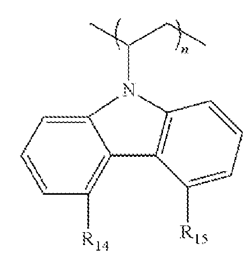


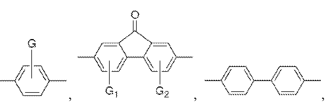


Applications Claiming Priority (2)
| Application Number | Priority Date | Filing Date | Title |
|---|---|---|---|
| US202363614257P | 2023-12-22 | 2023-12-22 | |
| US63/614,257 | 2023-12-22 |
Publications (1)
| Publication Number | Publication Date |
|---|---|
| WO2025136558A1 true WO2025136558A1 (en) | 2025-06-26 |
Family
ID=96138732
Family Applications (1)
| Application Number | Title | Priority Date | Filing Date |
|---|---|---|---|
| PCT/US2024/056284 Pending WO2025136558A1 (en) | 2023-12-22 | 2024-11-15 | Method for processing conductive polymer binder for electrochemical devices |
Country Status (1)
| Country | Link |
|---|---|
| WO (1) | WO2025136558A1 (en) |
Citations (4)
| Publication number | Priority date | Publication date | Assignee | Title |
|---|---|---|---|---|
| US4880508A (en) * | 1988-02-12 | 1989-11-14 | The United States Of America As Represented By The United States Department Of Energy | Water-soluble conductive polymers |
| US7960037B2 (en) * | 2004-12-03 | 2011-06-14 | The Regents Of The University Of California | Carbon nanotube polymer composition and devices |
| US9722252B2 (en) * | 2009-05-18 | 2017-08-01 | The Regents Of The University Of California | Electronically conductive polymer binder for lithium-ion battery electrode |
| US20230015653A1 (en) * | 2016-11-28 | 2023-01-19 | Sila Nanotechnologies, Inc. | High-capacity battery electrodes with improved binders, construction, and performance |
-
2024
- 2024-11-15 WO PCT/US2024/056284 patent/WO2025136558A1/en active Pending
Patent Citations (4)
| Publication number | Priority date | Publication date | Assignee | Title |
|---|---|---|---|---|
| US4880508A (en) * | 1988-02-12 | 1989-11-14 | The United States Of America As Represented By The United States Department Of Energy | Water-soluble conductive polymers |
| US7960037B2 (en) * | 2004-12-03 | 2011-06-14 | The Regents Of The University Of California | Carbon nanotube polymer composition and devices |
| US9722252B2 (en) * | 2009-05-18 | 2017-08-01 | The Regents Of The University Of California | Electronically conductive polymer binder for lithium-ion battery electrode |
| US20230015653A1 (en) * | 2016-11-28 | 2023-01-19 | Sila Nanotechnologies, Inc. | High-capacity battery electrodes with improved binders, construction, and performance |
Non-Patent Citations (1)
| Title |
|---|
| YAO WEILIANG, CHOUCHANE MEHDI, LI WEIKANG, BAI SHUANG, LIU ZHAO, LI LETIAN, CHEN ALEXANDER X., SAYAHPOUR BAHARAK, SHIMIZU RYOSUKE,: "A 5 V-class cobalt-free battery cathode with high loading enabled by dry coating", ENERGY & ENVIRONMENTAL SCIENCE, RSC PUBL., CAMBRIDGE, vol. 16, no. 4, 12 April 2023 (2023-04-12), Cambridge , pages 1620 - 1630, XP093332135, ISSN: 1754-5692, DOI: 10.1039/D2EE03840D * |
Similar Documents
| Publication | Publication Date | Title |
|---|---|---|
| Salini et al. | Toward greener and sustainable Li-ion cells: an overview of aqueous-based binder systems | |
| Wu et al. | Multiple hydrogel alginate binders for Si anodes of lithium-ion battery | |
| Bigoni et al. | Sodium alginate: a water-processable binder in high-voltage cathode formulations | |
| CN109148796B (en) | Acid scavenging functional diaphragm for lithium ion electrochemical cell functional performance | |
| Chai et al. | Chitosan, a new and environmental benign electrode binder for use with graphite anode in lithium-ion batteries | |
| Zheng et al. | A water-soluble binary conductive binder for Si anode lithium ion battery | |
| He et al. | Cyanoethylated carboxymethyl chitosan as water soluble binder with enhanced adhesion capability and electrochemical performances for LiFePO4 cathode | |
| JP5660112B2 (en) | Positive electrode for lithium ion secondary battery and lithium ion secondary battery | |
| Rao et al. | Multifunctional composite binder for thick high-voltage cathodes in lithium-ion batteries | |
| Wang et al. | Reversible cross-linked phosphorylate binder for recyclable lithium-sulfur batteries | |
| US9876232B2 (en) | Positive electrode for secondary battery, method for producing the same, and nonaqueous secondary battery | |
| FR2941817A1 (en) | PROCESS FOR THE PREPARATION OF AN ELECTRODE COMPOSITION | |
| CN106711460B (en) | An electrode slurry composition and its use for preparing electrodes and lithium ion batteries | |
| Wu et al. | Ionic network for aqueous-polymer binders to enhance the electrochemical performance of Li-ion batteries | |
| Güneren et al. | Novel alginate-based binders for silicon–graphite anodes in lithium-ion batteries: effect of binder chemistry on the electrochemical performance | |
| CN102099947A (en) | Composition for battery | |
| Huang et al. | Design of conductive binders for LiFePO4 cathodes with long-term cycle life | |
| Huang et al. | Enhanced electrochemical properties of LiFePO4 cathode using waterborne lithiated ionomer binder in Li-ion batteries with low amount | |
| Li et al. | Degradation mechanism of LiNi0. 8Co0. 1Mn0. 1O2 cathode after ambient storage and self-repairing strategy by electrolyte additive | |
| He et al. | Electrochemical performance of polysaccharides modified by the introduction of SO3H as binder for high-powered Li4Ti5O12 anodes in lithium-ion batteries | |
| Miao et al. | Enhancing the cycle life of recycled graphite materials from spent lithium-ion batteries via conductive polymer coating | |
| Deng et al. | A branched hydrogen-bonded cross-linking fluorine-free waterborne binder for highly stable lithium-ion battery | |
| Weng et al. | Improving the electrochemical performance of LiFePO4 cathode with novel water-soluble binders | |
| Jeong et al. | Lithiated cellulose nanofibers as a water-soluble binder for high-rate nanosized LiFePO4/C cathodes: Comparative degradation mechanisms across binder systems | |
| CN107482188B (en) | A kind of hollow core-shell structure composite material and its preparation method and application |
Legal Events
| Date | Code | Title | Description |
|---|---|---|---|
| 121 | Ep: the epo has been informed by wipo that ep was designated in this application |
Ref document number: 24908564 Country of ref document: EP Kind code of ref document: A1 |