WO2025134985A1 - かつらベース、かつら、かつらベース製造方法 - Google Patents
かつらベース、かつら、かつらベース製造方法 Download PDFInfo
- Publication number
- WO2025134985A1 WO2025134985A1 PCT/JP2024/044419 JP2024044419W WO2025134985A1 WO 2025134985 A1 WO2025134985 A1 WO 2025134985A1 JP 2024044419 W JP2024044419 W JP 2024044419W WO 2025134985 A1 WO2025134985 A1 WO 2025134985A1
- Authority
- WO
- WIPO (PCT)
- Prior art keywords
- wig
- base
- wig base
- yarn
- heat
- Prior art date
- Legal status (The legal status is an assumption and is not a legal conclusion. Google has not performed a legal analysis and makes no representation as to the accuracy of the status listed.)
- Pending
Links
Images


Classifications
-
- A—HUMAN NECESSITIES
- A41—WEARING APPAREL
- A41G—ARTIFICIAL FLOWERS; WIGS; MASKS; FEATHERS
- A41G3/00—Wigs
Definitions
- the present invention relates to a wig base, a wig, and a method for manufacturing a wig base.
- wigs are used to replace the lost hair.
- Full head wigs are made by implanting human hair (hereafter referred to as "human hair”) or artificially created hair (hereafter referred to as “artificial hair”) into a wig base.
- wigs have been known that use artificial skin made of synthetic resin for the parting of the hair on the wig base in order to achieve a natural appearance and prevent the wig from slipping off.
- Patent Document 1 a wig has been proposed in which hair is attached to a wig base made of a mesh-like elastic material.
- wig bases made of mesh-like elastic material can sometimes tighten around the head or roll up due to the elasticity of the material, leaving room for improvement in terms of texture and shape stability.
- the present invention was made in consideration of the above circumstances, and the problem it aims to solve is to provide a wig base and wig that have a better feel and better shape stability than conventional wig bases, as well as a method for manufacturing said wig base.
- the wig base of the present invention has a base, which is formed of covering yarn in which the outer periphery of a core material is covered with a covering material, and heat-sealing yarn is used as the core material and/or the covering material.
- the wig of the present invention comprises a wig base of the present invention and human hair and/or artificial hair implanted therein.
- the wig base manufacturing method of the present invention is a method in which a tubular net formed of covering yarns in which the outer periphery of heat-sealed yarns is covered with a covering material and/or a core material in which the outer periphery of a core material is covered with heat-sealed yarns is placed over a head model, and the tubular net is heated to mold the tubular net into a shape that fits the head model.
- the present invention provides a wig base and wig that has a better texture and better shape stability than conventional wig bases and wigs, as well as a method for manufacturing the wig base.
- FIG. 1A shows an example of a wig
- FIG. 1B shows an example of a wig base
- 1A shows an example of a single covering yarn
- FIG. 1B shows an example of a double covering yarn.
- 4(a) to 4(d) show an example of a front part.
- 4(a) to 4(d) show examples of back parts.
- 4(a) to (d) show an example of a mesh-like front part.
- 4(a) to (d) show an example of a mesh-like back part.
- FIG. 13 is an explanatory diagram of a modified wig.
- FIG. 9 is an explanatory diagram showing an example of a main body part of the wig in FIG. 8 .
- FIG. 9 is an explanatory diagram showing an example of a base part of the wig in FIG. 8 .
- FIG. 11 is an explanatory diagram showing another example of the base part.
- 9A to 9C are explanatory diagrams showing an example of a procedure for wearing the wig in FIG. 8.
- FIG. 11 is an explanatory diagram showing another example of a main body part of a wig.
- FIG. 11 is an explanatory diagram showing another example of a main body part of a wig.
- FIG. 11 is an explanatory diagram showing another example of a wig base part.
- FIG. 11 is an explanatory diagram showing another example of a main body part of a wig.
- FIG. 11 is an explanatory diagram showing another example of a main body part of a wig.
- 1 is a flowchart showing an example of a wig manufacturing process.
- FIG. 11 is a flowchart showing an example of a process for producing a head model.
- 4A and 4B show examples of head images measured using a coordinate measuring machine.
- (a) and (b) show an example of a head model produced using a three-dimensional modeling machine.
- FIG. 1 shows an example of a cross-sectional view of a hollow head model having through holes.
- 1 shows an example of a tubular net made with covering yarn.
- 1 is a flowchart showing an example of a wig manufacturing process.
- 13(a) to 13(c) show an example of the process from forming a cylindrical net to implanting hair.
- 13A to 13C show an example of a manufacturing process for a slip-prevention part when a front part, a back part and a ring-shaped part are used.
- 1 shows an example of a case where a front part and a back part made of a shape memory polymer are heated using a dryer.
- a wig 30 shown in Fig. 1(a) comprises a wig base 10 and hair 20.
- a wig base 10 of this embodiment comprises a base 11 , a whorl part 12 , and a slip-stop part 13 .
- the base 11 is the foundation of the wig base 10.
- the base 11 in this embodiment is a mesh-like (net-like) member shaped to fit the shape of the wearer's head, and is preferably seamless. Being seamless, the head is not irritated by the sewing thread, and a comfortable fit is obtained. Since the base 11 is mesh-like, it is lightweight and has excellent breathability.
- the base 11 can be manufactured using various machines such as a seamless knitting machine, a flat knitting machine, a hosiery machine, etc., or it can be manufactured by hand knitting.
- it can be made using flat knitting (plain knitting, stockinette knitting), rib knitting (rib knitting, elastic knitting, rib knitting), pearl knitting (garter knitting, links, double head knitting), thermal knitting (waffle knitting, honeycomb knitting), pique knitting, reversible pique knitting (reversible mesh), smooth knitting (interlock), reverse pile knitting (fleece knitting, brushed fleece knitting), jacquard knitting, intarsia knitting, etc.
- covering yarn includes a yarn material 14 in which a covering material (sheath yarn) 14b is wound in a coil shape around the outer circumference of a core material 14a, as shown in Figures 2(a) and (b).
- the covering yarn 14 can be a single covering yarn in which the covering material 14b is wrapped around it in a single layer, as shown in Figure 2(a) (single covering yarn), or a double covering yarn in which the covering material 14b is wrapped around it in a double layer, as shown in Figure 2(b) (double covering yarn).
- the core material 14a can be made of heat-sealed yarn.
- Heat-sealed yarn has the property of melting when heated and solidifying (curing) when cooled.
- Examples of heat-sealed yarn include yarns made of various synthetic fiber materials such as nylon (polyamide) and polyester, which have lower melting points than normal.
- Covering yarn 14, which uses heat-sealed yarn as the core material, can be molded into a specified shape by applying heat and then curing, allowing the shape to be maintained.
- the heat-sealed yarn can be, for example, low-melting nylon/polyamide fiber, low-melting polyester fiber, or other thermoplastic polymers or thermoplastic elastomers with adjusted melting points.
- the heat-sealed yarn may be made of two or more different fiber materials.
- the heat-sealed yarn may have a double structure, with a synthetic fiber material with a normal melting point in the center and a synthetic fiber material with a lower melting point than normal being used to create a core-sheath structure.
- the surrounding low-melting-point material melts with heat and functions as a heat-sealed yarn, while the center does not melt with heat and can maintain a predetermined shape, elasticity, etc.
- the heat-sealed yarn may be a composite material made of two or more materials with different melting points.
- Heat-sealing yarns are, for example, nylon fibers that melt at about 71°C in hot water and about 118°C in dry heat (105-125°C), or at about 62°C in hot water and about 105°C in dry heat (95-115°C).
- Heat-sealed yarns are made of multiple core-sheath composite filaments (heat-sealed polyester fibers) that have a core made of high-viscosity polyester resin with a melting point of about 250°C and a sheath made of crystalline polyester resin with a melting point of about 180°C (low melting point), which is lower than the melting point of the core.
- the heat-sealed yarn is, for example, a low-melting polyamide fiber with a melting point of 98 to 130°C.
- heat-sealing thread for example, one that has a multifilament structure using multiple filaments and is easy to fuse together when melted can be used.
- a composite filament using multiple filaments with a sheath portion on the outside of a core portion can be used.
- the heat-sealing yarn shown here is just one example, and various types of heat-sealing yarn can be used.
- a hot water melting point of about 60 to 130°C preferably a hot water melting point of about 60 to 90°C, or a dry heat melting point of about 90 to 150°C, preferably a dry heat melting point of about 100 to 135°C can be used.
- the melting point of the heat-sealed yarn can be evaluated by various methods, for example, by melting point measurement according to JIS L1013:2010.
- the heat-sealed yarn used as the core material 14a is preferably one with a melting point of 90 to 140°C.
- the covering material 14b covers the outer circumference of the core material 14a. Normally, molded products using heat-sealed yarns become hard when the fused yarn melts and solidifies, so if the heat-sealed yarn is used as is, it may cause discomfort when it comes into contact with the skin.
- the covering material 14b by providing a covering material 14b around the outer periphery of the heat-sealed thread, it becomes more comfortable against the skin and reduces the discomfort felt when it touches the skin.
- the covering material 14b also has the effect of increasing the strength of the core material 14a and therefore the strength of the wig base 10, reducing the risk of the wig base 10 being damaged when the hair is planted.
- the covering material 14b can be made of various materials, such as nylon, polyester, rayon, polyurethane, acrylic, polypropylene, polyethylene, synthetic protein, thermoplastic elastomer, cotton, silk, hemp, paper, wool, etc.
- thermoplastic or thermosetting chemical fibers it is desirable that the melting point is higher than the melting point of the heat-sealed thread used as the core material, preferably by 10°C or more, and more preferably by 20°C or more. It is preferable to use a covering material 14b that is the same or a similar color as the wearer's skin (scalp), or the same or a similar color as the hair.
- the main expectation for the heat-sealed yarn is shape stability (ability to maintain a fit to the shape of the head).
- shape stability ability to maintain a fit to the shape of the head.
- both the core material 14a and the covering material 14b may be made of the above-mentioned heat-sealed thread.
- the covering material 14b can be heat-sealed yarn and the core material 14a can be made of ordinary synthetic or natural fibers, as opposed to the present embodiment.
- covering yarn when using double covering yarn, it is also possible to use covering with two different materials.
- two different materials of ordinary natural or synthetic fibers it is also possible to use two different materials of heat-sealed yarn, or it is also possible to use one of the materials as a heat-sealed yarn and the other as an ordinary fiber material.
- the type of material to be used for the core material 14a and covering material 14b, and the type of material to be used for each of the two covering materials 14b when double covering yarn is used are matters that a person skilled in the art can change as appropriate in order to pursue the desired texture, shape stability, and ease of molding after reading the disclosure of this specification.
- the whorl part 12 is a member provided near the top of the wig base 10.
- the whorl part 12 has hair (hereinafter referred to as "whorl hair") 12b planted in a base part 12a made of artificial skin, knitted fabric, woven fabric, lace material, etc.
- the base part 12a is preferably the same color as the base part 11 or a similar color, in other words, the same color as the wearer's skin or a similar color.
- the artificial skin is used to make the parting look natural, like the wearer's bare skin.
- the whorl hair 12b can be made of human hair, artificial hair, etc.
- the whorl hair 12b can be made by combining multiple human hairs or artificial hairs of the same or different lengths.
- the whorl hair 12b is planted so that it penetrates from the outer side to the inner side of the wig base 10, and then penetrates back to the outer side.
- the whorl hair 12b is planted so that it looks like a natural whorl.
- the whorl part 12 is configured as a separate part from the base 11. By configuring the whorl part 12 as a separate part from the base 11, it is possible to replace only the whorl part 12, which wears out easily.
- the whorl part 12 can be attached to the base 11 by crimping, sewing, or other methods.
- the whorl part 12 can also include not only the whorl part, but also the parting part. If artificial skin is used, the parting part can be made to look natural, like bare skin.
- the slip-stop part 13 is a member that prevents the wig base 10 from slipping or coming off.
- the slip-stop part 13 is provided around the face (the part that comes into contact with the wearer's skin) on the inner surface of the base 11.
- the slip-stop part 13 is also expected to have the effect of reinforcing the wig base 10 and preventing fraying.
- the anti-slip part 13 can be attached to the base 11 by crimping, sewing, or other methods.
- the anti-slip part 13 is ring-shaped (hairband-shaped) and spans the left head, front head, right head, and back of the head, and the area for both ears is cut so that both ears are exposed.
- the slip-stop part 13 can be made of, for example, thermoplastic elastomer, silicone rubber, natural rubber (NR), styrene butadiene rubber (SBR), chloroprene rubber (CR), acrylonitrile butadiene rubber (NBR), urethane rubber (U), thermoplastic polyurethane (TPU), etc. It is preferable that the slip-stop part 13 is made of a material with a higher friction resistance than the covering thread 14.
- the anti-slip part 13 can also be provided with a size adjustment tool (adjuster) 15.
- the adjuster 15 can be, for example, a thin plate material with two holes, a string material to be inserted into the holes, and a string material holder to hold the string material (a so-called pig nose with a lock), a hook and loop fastener, etc. Other things can also be used for the adjuster 15.
- the anti-slip part 13 can be manufactured from a shape-memory polymer that can be output by a 3D printer.
- the shape-memory polymer referred to here is a polymer that has the property of being able to restore its original shape by heating it to a specified temperature or higher, even if the shape is deformed after molding.
- the shape-memory polymer may be a shape-memory polymer filament, etc.
- the wig is made of a shape-memory polymer, and when the anti-slip part 13 is heated to a specified temperature with a hair dryer or the like while the wig is attached to the head, it is restored to its original shape, and then the wig is fitted to the wearer's own head before being cooled again, allowing the wig to fit the head even better.
- the specified temperature is the so-called glass transition point (Tg), and is approximately 50 to 70°C, preferably approximately 55°C. If the material regains its shape at temperatures above 55°C, in other words if the material does not regain its shape at temperatures below 55°C, then unintentional deformation can be prevented even during hot periods such as midsummer.
- Tg glass transition point
- the shape can be flat (for example, a sheet-like shape) or three-dimensional. It can also be shaped to fit a specific person's head (head model M) or a general-purpose shape.
- generic parts when printing parts with generic shapes (hereafter referred to as "generic parts"), it is preferable to use a hair dryer or other tool to shape the generic parts to fit individual heads. It is preferable to prepare generic parts in multiple sizes (for example, small, medium, and large) in advance.
- the anti-slip part 13 can be made up of one part (for example, a ring-shaped part), or it can be made up of multiple parts.
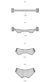
- a front part 13a and a back part 13b can be prepared and the two can be connected with hook-and-loop fasteners, tape, rubber, adjusters, etc. to form a ring shape.
- the front part 13a and the back part 13b can be in various shapes.
- An example of the shape of the front part 13a is shown in Figures 3(a) to (d)
- an example of the shape of the back part 13b is shown in Figures 4(a) to (d).
- the front part 13a and the back part 13b can also be in a mesh shape, as shown in Figures 5(a) to (d) and 6(a) to (d).
- front part 13a and the back part 13b can be in a frame shape with multiple inner members 13e on the inside of a peripheral frame 13d as shown in Figures 7(a) and (b).
- the inner members 13e can be arranged vertically, horizontally, or diagonally, regularly or irregularly.
- the peripheral frame 13d can be omitted, and the part can be made up of only multiple inner members 13e connected together.
- an inner surface part 13f made of a soft material that is unlikely to damage the skin (such as a thermoplastic elastomer or silicone) on the surface that comes into contact with the wearer's skin.
- the shape of the inner part 13f can be a ring shape that conforms to the shape of the head, or a shape similar to the shape of the parts made of shape-memory polymer (front part 13a and back part 13b).
- a front part 13a with a frame shape as shown in FIG. 7(a) it is preferable to attach an inner part 13f with the same shape as the frame shape as shown in FIG. 7(c) to the surface that comes into contact with the wearer's skin.
- a back part 13b with a frame shape as shown in FIG. 7(b) it is preferable to attach an inner part 13f with the same shape as the frame shape as shown in FIG. 7(d) to the surface that comes into contact with the wearer's skin.
- the hair 20 is a part that constitutes the hair of the wig 30.
- the hair 20 can be made of human hair, artificial hair, etc.
- the hair 20 can be made by combining multiple human hairs or artificial hairs of the same or different lengths.
- the hair 20 is planted so that it penetrates from the outer side to the inner side of the wig base 10 (specifically, the base 11 and the anti-slip part 13), and then penetrates back to the outer side again.
- the wig base 10 is made of covering thread 14, in which the outer periphery of the core material 14a is covered with covering material 14b, so that it is stronger than conventional wig bases and the risk of damage to the wig base 10 during planting can be reduced.
- knots may form on the inner side of wig base 10, which may touch the skin and cause itching.
- a backing fabric or the like may be provided on the inner side of wig base 10 after hair 20 is planted, to prevent the knots from directly touching the skin.
- the wig base 10 and wig 30 described here are merely examples, and the configuration of the wig base 10 and wig 30 of the present invention is not limited to the configuration of this embodiment.
- the wig base 10 and wig 30 of the present invention can be modified by adding, omitting, or replacing components within the scope of achieving the intended purpose.
- the wig base 10 of the present invention may not have either or both of the whorl part 12 and the anti-slip part 13.
- the material of the wig base 10 of the present invention does not use heat-sealed thread, but is instead made of ordinary natural or synthetic fibers (see paragraph 0033, etc.) that can be used for the covering material 14b, and instead a shape-memory polymer is used for the anti-slip part 13, thereby providing a wig with excellent texture and fit to the head, which is also within the scope of the present invention.
- the wig 30 is exemplified as one in which the base 11, the whorl part 12, the anti-slip part 13 and the hair 20 are integrally constructed, but as a variant, the wig 30 can also be constructed of two or more separate parts.
- Figure 8 shows an example of a wig 30 made up of two or more separate parts, in which the base 11, whorl part 12 and hair 20 are made up as a single part, and the anti-slip part 13 is made up as a separate part.
- the latter functions as a base part that is attached to the head, and the former functions as a main part that is attached to the base part (anti-slip part 13) attached to the head.
- the basic configuration of the base 11, whorl part 12, and hair 20 of this modified example is the same as that of the above embodiment.
- the difference is that the base 11 is provided with a fixing device 16 and a sideburn sticker attachment part 17.
- the differences from the above embodiment will be mainly explained, and explanations of the same parts as the above embodiment will be omitted as appropriate.
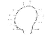
- the base 11 of this modified example is a seamless (whole garment) member shaped to fit the head.
- the periphery of the opening on the lower end of the base 11 has protruding parts at positions corresponding to the sideburns and the nape of the neck that protrude lower than the other parts of the periphery of the opening (hereinafter, the protruding parts at the positions corresponding to the sideburns are referred to as the "first protruding part 11a" and the “second protruding part 11b", and the protruding part at the position corresponding to the nape of the neck is referred to as the "third protruding part 11c").
- the parts corresponding to the ears have upwardly recessed parts 11d to accommodate the ears.
- the first protruding portion 11a and the second protruding portion 11b shown in FIG. 9 are generally trapezoidal in shape, but the first protruding portion 11a and the second protruding portion 11b can have various shapes, such as a shape with an arcuate tip.
- the third protruding portion 11c is generally trapezoidal in shape, but the third protruding portion 11c can have various shapes, such as a shape with an arcuate tip.
- the lower ends of the first protruding portion 11a and the second protruding portion 11b are provided with sideburn sticker attachment portions 17 for attaching sideburn stickers S1 (Figs. 13(a) and (b)).
- Sideburn stickers S1 are stickers with a picture or photograph of sideburns printed (displayed) on their surface, and are used by attaching one part to sideburn sticker attachment portion 17 and the other part near the front of the wearer's ear.
- the fixing device 16 is a member for fixing the integrally constructed base 11, whorl part 12, and hair 20 (main body part) to the slip prevention part 13 (base part).
- a comb-shaped fastener as shown in FIG. 9 or a clip with clamping parts on both longitudinal ends can be used as the fixing device 16.
- Fixing devices 16 of other shapes and structures can also be used.
- fasteners 16 By providing the fasteners 16 in such a position, it is possible to prevent the main body parts from floating not only near the center of the back of the head, but also on both sides.
- the same fasteners can be used, but different fasteners can also be used.
- the positions and number of fasteners 16 shown in FIG. 9 are merely examples, and the positions and number of fasteners 16 may be other than these.
- the anti-slip part 13 is a part that is attached to the head, and is a part that serves as a base for fixing the base 11, whorl part 12, and hair 20 (main body part), which are constructed as a single unit.
- the anti-slip part 13 of this modified example includes a front part 13a, a nape part 13g, and a connector 13h.
- the front part 13a and the nape part 13g are connected by a connector 13h such as a hook-and-loop fastener, tape, rubber, hook, or adjuster, forming a series of rings.
- the front part 13a has a two-layer structure made by bonding a shape-memory material with shape memory and temperature dependency to a durable mesh material.
- the shape-memory material is on the skin side, and the mesh material is on the outside.
- the shape-memory material used in this modified example has the property of sensing body temperature and becoming flexible. This material does not have a very high tensile strength, so durability is ensured by attaching a mesh material. In addition, this material does not have a high level of breathability, so breathability is ensured by providing micropores.
- the micropores can be formed using a laser, etc.
- the configuration and material of the front part 13a shown here are just an example, and the front part 13a can be made of a different configuration and material.
- the front part 13a can be the same as the front part 13a in the above embodiment.
- the nape part 13g of this modified example is a part that is applied to the position of the head that corresponds to the nape of the neck, and includes a mesh-like (net-like) nape part base 13i that serves as a base, and hair (hereafter referred to as "rear hair") 13j that is provided on the nape part base 13i.
- the rear hair 13j can be human hair and/or artificial hair, and can be constructed by combining multiple human hairs and/or artificial hairs of the same or different lengths.
- the rear hair 13j can be planted in the same manner as the whorl hair 12b and the hair 20 planted in the base 11, or it can be attached to the surface of the nape part base 13i by sewing, gluing, or other methods.
- the inner surface (skin side) of the nape part base 13i is provided with a lining material.
- the lining material is a material that comes into direct contact with the skin, and can be made of thermoplastic elastomer, silicone rubber, natural rubber (NR), styrene butadiene rubber (SBR), chloroprene rubber (CR), acrylonitrile butadiene rubber (NBR), urethane rubber (U), thermoplastic polyurethane (TPU), etc.
- the lower end of the nape part 13g of this modified example is provided with a nape sticker attachment section 18 for attaching a nape sticker S2 (described later, Figs. 14(a) and (b)).
- the nape sticker S2 is a sticker on which a picture or photograph of the nape is printed (displayed), and is used by attaching a part of it to the nape sticker attachment section 18 and the other part to the wearer's neck.
- the nape sticker attachment part 18 is a separate part from the nape part 13g.
- the nape sticker attachment part 18 is attached to the nape part 13g (nape part base 13i) by various adhesive means such as glue or adhesive tape.
- the nape sticker attachment part 18 can be made of a material (polyurethane, polyurethane-based thermoplastic elastomer, elastomer, etc.) that makes it easy to attach the nape sticker S2.
- the nape sticker attachment part 18 can be the same color as the wearer's skin or a similar color, or can be colorless and transparent.
- the shape, material, and color of the nape sticker attachment part 18 may be other than those described above. It is preferable that the nape sticker attachment part 18 is located in a position hidden by the rear hair 13j (inside the rear hair 13j) when the hair 20 is down.
- the front part 13a and the nape part 13g are connected by a connector 13h.
- the connector 13h shown in FIG. 10 comprises a band 13k attached to one end of the front part 13a, a loop surface 13m attached to part of the outer surface of the band 13k, a hook surface 13n attached to another part of the outer surface of the band 13k, and a fold-back device 13p attached to the other end of the front part 13a.
- the nape part 13g is fixed to the inside of the band 13k.
- the front part 13a and nape part 13g are placed on the head, the band 13k is passed through the fold-over tool 13p and folded back, and the hook surface 13n and loop surface 13m of the folded band 13k are pressed against each other, thereby connecting the front part 13a and nape part 13g.
- an anti-slip band 13r the surface of which that comes into contact with the skin is made of an anti-slip material, can be placed inside the base 13i of the nape part.
- the anti-slip band 13r can be made of the same material as the front part 13a, or a different material.
- the anti-slip band 13r can also be integrated with the front part 13a or can be separate.
- the anti-slip band 13r is provided along the width direction of the inner surface of the nape part 13g, and serves to prevent the nape part 13g from slipping from its designated position on the head.
- the nape part 13g When an anti-slip band 13r is placed inside the base 13i of the nape part, for example, the nape part 13g is fixed to the outside of the anti-slip band 13r provided on one end of the front part 13a.
- a band 13k having a loop surface 13m and a hook surface 13n on its outer surface is fixed to the outer surface of the nape part 13g.
- the front part 13a and nape part 13g can be connected by folding the band 13k through the folding tool 13p and folding it back while the front part 13a and nape part 13g are placed on the head, and then pressing the hook surface 13n and the loop surface 13m of the folded band 13k together.
- the nape part 13g is placed on the head with the anti-slip band 13r in contact with the skin.
- the band 13k does not touch the head and no step is created, resulting in a good fit.
- the upper end of the nape part 13g can be made to be flush with the upper end of the band 13k, or it can be positioned lower than the upper end of the band 13k.
- a portion of the sideburn sticker S1 can be attached in advance to the sideburn sticker attachment portion 17.
- a portion of the nape sticker S2 can be attached in advance to the nape sticker attachment portion 18.
- the fixing device 16 is provided on the base 11 as an example, but the fixing device 16 can also be provided on the anti-slip part 13, or on both the base 11 and the anti-slip part 13.
- both the sideburn sticker attachment section 17 and the nape sticker attachment section 18 can be provided on the anti-slip part 13.
- both the sideburn sticker attachment section 17 and the nape sticker attachment section 18 can be provided on the base 11.
- the sideburn sticker attachment section 17 and the nape sticker attachment section 18 can also be provided on both the base 11 and the anti-slip part 13.
- the front hairline sticker attachment part 19 can be a shape that naturally fits the front hairline, such as a rectangle or a curved shape.
- the front hairline sticker attachment part 19 can be made of a material that makes it easy to attach a front hairline sticker, such as polyurethane, polyurethane-based thermoplastic elastomer, or elastomer.
- the front hairline sticker attachment part 19 can be attached to the base 11 by various adhesive means, such as adhesive or adhesive tape.
- the front hairline sticker attachment portion 19 can be the same color as the wearer's skin or a similar color, or can be colorless and transparent.
- the shape, material, and color of the front hairline sticker attachment portion 19 may be other than those described above. It is preferable to provide the front hairline sticker attachment portion 19 in a position hidden by the hair 20 (inside the hair 20).
- the front hairline sticker attachment section 19 may be plain and unmarked, but it may also be printed (displayed) with a picture or photo of the front hairline, similar to the front hairline sticker.
- the front hairline sticker attachment section 19 may be provided as needed, and may be omitted if not required.
- the nape part 13g which is provided at a position corresponding to the nape of the neck, is provided on the anti-slip part 13, but the nape part 13g can also be provided on the main body part (e.g., the base 11), in other words, it can be configured as part of the base 11.
- the third protruding part 11c of the base 11 can be made larger by approximately the same amount as the nape part base 13i, and the hair 20 corresponding to the rear hair 13j can be attached to the second protruding part 11b.
- the hair 20 can be human hair and/or artificial hair, and can be configured by combining multiple human hairs and/or artificial hairs of the same or different lengths.
- the nape part 13g of the non-slip part 13 can be omitted as shown in FIG. 17.
- a nape sticker attachment part 18 similar to the nape sticker attachment part 18 provided on the nape part 13g can be provided on the lower end side of the third protruding part 11c.
- the wig base 10 can also be configured as shown in Figures 18 and 19.
- the first protruding portion 11a and the second protruding portion 11b have an arc-shaped tip.
- a strip-shaped first bag part 11f is provided on the lower end side of the inner surface of the base 11, from the first protruding portion 11a to one end side of the third protruding portion 11c.
- a strip-shaped second bag part 11g is attached on the lower end side of the inner surface of the base 11, from the second protruding portion 11b to the other end side of the third protruding portion 11c.
- the first bag part 11f and the second bag part 11g can be made of a different material from the base 11 or the same material.
- the first bag part 11f contains a tape-like first connecting band 11h that is connected to the first protruding portion 11a.
- a first hook 11j is provided at the tip of the first connecting band 11h that passes through the first bag part 11f.
- the second bag part 11g contains a tape-like second connecting band 11i that is connected to the second protruding portion 11b.
- a second hook 11k is provided at the tip of the second connecting band 11i that passes through the second bag part 11g.
- a hook strap member 11m capable of engaging the first hook 11j and the second hook 11k is fixed to the lower end side of the outer surface of the third protruding portion 11c.
- the hook strap member 11m is provided with multiple hook portions 11n, and the circumference of the wig base 10 can be adjusted by changing the hooking positions of the first hook 11j and the second hook 11k.
- first bag part 11f, the second bag part 11g, the first connecting band 11h, the second connecting band 11i, and the hook strap member 11m are provided on the inner surface of the base 11, but some or all of these parts can also be provided on the outer surface of the base 11.
- the wig base 10 shown in Figure 18 has a whorl part 12 that covers the entire width of the head.
- the whorl part 12 can be made of artificial skin, lace, or the like.
- the whorl part 12 can also be narrower in width than the whorl part 12 in Figure 18.
- the whorl part 12 can be a part that includes a part other than the whorl and the hairline of the front hair.
- the fixing device 16 can be omitted.
- the part that is attached to the back of the head (the nape side or the back of the head side) can be fixed directly to the head with both connecting bands 11h, 11i without being fixed to the non-slip part 13 attached to the head.
- the part that is attached to the front of the head can be placed over the non-slip part 13 and fixed to the non-slip part 13 with an adhesive such as glue or double-sided tape.
- the base 11 can also be constructed by combining a seamless mesh material made with heat-sealed thread with a different material such as lace.
- the front part can be made of lace material and the back part can be made of seamless mesh material made with heat-sealed thread.
- a silicone member or the like can be interposed between the lace material and the seamless mesh material or in the nape area. These materials can be connected by sewing, adhesive, or the like.
- the base 11 configured in this manner can be provided with size adjustment members as necessary.
- size adjustment members include those using the first bag part 11f, second bag part 11g, first connecting band 11h, second connecting band 11i, first hook 11j, second hook 11k, and hook strap member 11m shown in Figures 18 and 19, as well as those using an elastic cord and the aforementioned pig nose with lock.
- the base 11 in the above embodiment, modified examples, and other modified examples can be manufactured using, for example, a seamless elastic tubular net N.
- the tubular net N can be knitted using the various methods described above, such as plain knitting.
- the tubular net N can be constructed using one of the following types: covering yarn 14 with heat-sealed yarn as core material 14a, covering yarn 14 with heat-sealed yarn as covering material 14b, or heat-sealed yarn without covering material 14b. It can also be constructed using a combination of two or more types.
- each type of yarn has different characteristics, such as covering yarn 14 with heat-sealed yarn as the core material 14a having a nice texture, and covering yarn 14 with heat-sealed yarn as the covering material 14b being easy to melt and mold, the appropriate yarn can be selected and used according to the purpose.
- covering yarn 14 which has excellent formability (specifically, covering yarn 14 with heat-sealed yarn as covering material 14b or heat-sealed yarn without covering material 14b), and construct other areas such as the top of the head with a different covering yarn 14, etc.
- the cylindrical net N is preferably large enough to completely cover the entire head model M.
- it can be sized appropriately to have a length of about 20 to 80 cm, preferably about 30 to 50 cm, and a circumference (half body) of about 10 to 30 cm, preferably about 15 to 20 cm.
- Both longitudinal ends of the tubular net N are closed, and one end is cut off for use when manufacturing the wig base 10.
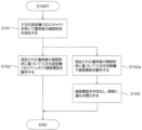
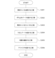
- the wig base 10 and wig 30 of this embodiment can be manufactured, for example, as shown in FIG. 20, through process S100 of making a head model M, process S200 of making a tubular net N, and process S300 of making the wig 30. Note that either process S100 of making the head model M or process S200 of making the tubular net N can be performed first, or they can be performed in parallel.
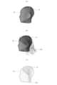
- the head model M can be produced through step S101 of measuring the wearer's head shape using a three-dimensional measuring machine (a so-called 3D scanner), and step S102 of producing the head model M with a three-dimensional modeling machine (a so-called 3D printer) based on the measured head shape of the wearer.
- a three-dimensional measuring machine a so-called 3D scanner
- a three-dimensional modeling machine a so-called 3D printer
- the three-dimensional modeling machine can be an existing 3D printer or the like.
- the 3D printer can be an existing one that employs various methods, such as powder sintering additive manufacturing, photolithography, inkjet, and inkjet powder additive manufacturing.
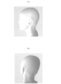
- An example of a head model M produced by a three-dimensional modeling machine is shown in Figures 23(a) and (b).
- Step S303 of cutting the cylindrical net-- In the step S303 of cutting the tubular net N, the excess portion of the tubular net N provided with the anti-slip parts 13 is cut off and formed into a cap shape (to obtain the cap-shaped base portion 11).
- the part including the base 11, the whorl part 12, and the hair 20 can be manufactured through, for example, a step S301 of forming the cylindrical net N, a step S303 of cutting the cylindrical net N, a step S304 of providing the whorl part 12, and a step S305 of planting the hair 20.
- a step S301 of forming the cylindrical net N a step S303 of cutting the cylindrical net N
- a step S304 of providing the whorl part 12 and a step S305 of planting the hair 20.
- the sideburn sticker attachment part 17 and the fixing device 16 described above are provided on the base 11 as necessary.
- the step S305 of planting the hair 20 can be carried out prior to the step S303 of cutting the tubular net N and the step S304 of providing the whorl part 12, in other words, following the step S301 of forming the tubular net N.
- a hairline lace part can also be attached.
- the connector 13h is attached to the front part 13a and the nape part 13g, which are prepared in advance.
- the nape part 13g is provided with the rear hair 13j and the nape sticker attachment part 18 in advance or afterwards.
- the rear hair 13j can be planted in the nape part base 13i, or can be attached to the surface of the nape part base 13i by a method such as sewing or gluing.
- the wig base 10, wig 30, and wig base manufacturing method of the present invention are not limited to the configurations of the above-mentioned embodiments.
- the wig base 10, wig 30, and wig base manufacturing method of the present invention can be modified as appropriate, such as by adding, replacing, or omitting configurations, to the extent that the intended purpose can be achieved.
- the configurations of the above embodiment and the modified examples can be added to or replaced with each other.
- the sideburn sticker attachment part 17 described in the modified example can be provided on the base 11 of the wig base 10 of the above embodiment, and the nape sticker attachment part 18 described in the modified example can be provided on the anti-slip part 13 of the above embodiment.
- the "ease of molding” evaluation is an evaluation of the molding process when manufacturing the wig base.
- the molding process for the wig bases in Examples 1 to 4 was all carried out manually by ironing the seamless knitted fabric attached to a head model. This molding process was evaluated on a 5-point scale by experienced workers engaged in wig development, etc., who compared the ease of ironing, ease of deformation, and ease of hardening, with "5" being assigned to ease of molding that was the same as that of heat-fused yarn itself and "1" being assigned to ease of molding that was impossible.
- Table 1 shows a comparison of the covering yarns used in each wig base of Examples 1 to 4.
- the covering yarn used for the wig base in Example 1 is a double covering yarn that uses 100 denier Flor (registered trademark) as the core material and 70 denier nylon as the covering material.
- denier which is the unit of measurement for fineness (fiber thickness), is indicated as "d”.
- the covering yarn used for the wig base in Example 2 is a double covering yarn that uses 50 denier Joiner (registered trademark) as the core material and 70 denier nylon as the covering material.
- the covering yarn used for the wig base in Example 3 is a single covering yarn made of 70 denier nylon twisted together as the core material and 50 denier joiner as the covering material.
- the covering yarn used for the wig base in Example 4 is a single covering yarn with polyurethane as the core material and 70 denier nylon and 50 denier joiner as the covering materials.
- the two types of covering materials are top twisted for the former and bottom twisted for the latter.
- Table 2 shows the evaluation results for each wig base regarding "feel,””shapestability,” and “ease of molding.”
- Example 1 was rated “5" and Example 2 was rated “4,” while Examples 3 and 4 were rated “3" or “2.”
- Examples 1 and 2 used covering yarn in which the outer circumference of the heat-sealed yarn was covered with a covering material. From this, it was confirmed that by covering the outer circumference of the heat-sealed yarn with a covering material, as in Examples 1 and 2, the texture (feel to the skin) was improved.
- Example 1 was rated “4”
- Examples 2 and 3 were rated “3”
- Example 4 was rated “2.”
- Example 1 was rated “4”
- Examples 2 and 3 were rated “3”
- Example 4 was rated “2.”
- heat-sealed yarn for the core material and covering it with a covering material, it is possible to improve the texture while maintaining the shape stability and ease of molding provided by the heat-sealed yarn.
- heat-sealed yarn is used for the covering material rather than the core material, as in Examples 3 and 4, molding can be easily carried out without heat being transferred to the center of the core material.
- Experiment 2 The applicant of the present invention conducted an experiment (hereinafter referred to as "Experiment 2") to confirm molding using heated water.
- the outline and results of Experiment 2 are as follows.
- a wig base was made using double covering yarn with 100 denier flor as the core material and 70 denier nylon as the covering material, and the wig base was placed on a head model (in experiment 2, a substitute head model was used instead of one created by a 3D printer), and the wig base was immersed in hot water at a temperature of 80°C (water temperature) and heated. The immersion time was 20 minutes. After immersion, the wig base was removed from the head model to check whether it maintained its shape.
- the present invention can be particularly suitably used as a wig base 10 for the entire head, a wig 30 for the entire head, and a method for manufacturing a wig base 10 for the entire head.
Landscapes
- Engineering & Computer Science (AREA)
- Textile Engineering (AREA)
- Professional, Industrial, Or Sporting Protective Garments (AREA)
Priority Applications (1)
| Application Number | Priority Date | Filing Date | Title |
|---|---|---|---|
| JP2025506987A JPWO2025134985A1 (https=) | 2023-12-18 | 2024-12-16 |
Applications Claiming Priority (2)
| Application Number | Priority Date | Filing Date | Title |
|---|---|---|---|
| JP2023212843 | 2023-12-18 | ||
| JP2023-212843 | 2023-12-18 |
Publications (1)
| Publication Number | Publication Date |
|---|---|
| WO2025134985A1 true WO2025134985A1 (ja) | 2025-06-26 |
Family
ID=96137153
Family Applications (1)
| Application Number | Title | Priority Date | Filing Date |
|---|---|---|---|
| PCT/JP2024/044419 Pending WO2025134985A1 (ja) | 2023-12-18 | 2024-12-16 | かつらベース、かつら、かつらベース製造方法 |
Country Status (2)
| Country | Link |
|---|---|
| JP (1) | JPWO2025134985A1 (https=) |
| WO (1) | WO2025134985A1 (https=) |
Citations (4)
| Publication number | Priority date | Publication date | Assignee | Title |
|---|---|---|---|---|
| JPS5352770A (en) * | 1976-10-18 | 1978-05-13 | Clifton John David | Mesh fabric and usage of same |
| JP2008169540A (ja) * | 2007-01-12 | 2008-07-24 | Himo Inc | かつら用キャップネットの解れ防止処理方法 |
| KR20200098946A (ko) * | 2019-02-13 | 2020-08-21 | (주)하이모 | 가발 및 그 제작방법 |
| JP2023026258A (ja) * | 2021-08-12 | 2023-02-24 | 順子 池野 | セパレーションネオウィッグ |
-
2024
- 2024-12-16 JP JP2025506987A patent/JPWO2025134985A1/ja active Pending
- 2024-12-16 WO PCT/JP2024/044419 patent/WO2025134985A1/ja active Pending
Patent Citations (4)
| Publication number | Priority date | Publication date | Assignee | Title |
|---|---|---|---|---|
| JPS5352770A (en) * | 1976-10-18 | 1978-05-13 | Clifton John David | Mesh fabric and usage of same |
| JP2008169540A (ja) * | 2007-01-12 | 2008-07-24 | Himo Inc | かつら用キャップネットの解れ防止処理方法 |
| KR20200098946A (ko) * | 2019-02-13 | 2020-08-21 | (주)하이모 | 가발 및 그 제작방법 |
| JP2023026258A (ja) * | 2021-08-12 | 2023-02-24 | 順子 池野 | セパレーションネオウィッグ |
Also Published As
| Publication number | Publication date |
|---|---|
| JPWO2025134985A1 (https=) | 2025-06-26 |
Similar Documents
| Publication | Publication Date | Title |
|---|---|---|
| EP1832187A1 (en) | Wig and process for producing the same | |
| US20070157941A1 (en) | Detachable hair bang | |
| TW200836654A (en) | Wig and manufacturing method of the same | |
| JP2007321282A (ja) | かつら用透湿性素材及びこの透湿性素材を有するかつら又はかつら用下地キャップ | |
| FI129667B (en) | Body-worn device | |
| JP5016447B2 (ja) | かつら | |
| WO2025134985A1 (ja) | かつらベース、かつら、かつらベース製造方法 | |
| JP2011084830A (ja) | かつら | |
| JP6231146B2 (ja) | かつら | |
| JP4883584B2 (ja) | 自毛活用型かつら | |
| JPH1193010A (ja) | ヘアピースおよびそのネットベースの編成方法 | |
| JP5101144B2 (ja) | かつらベース及びかつら | |
| JP2001299791A (ja) | 顎バンド | |
| JP3623444B2 (ja) | フード | |
| JP6170269B1 (ja) | 頭部保護具 | |
| JP3245627U (ja) | ウィッグ構造 | |
| CN214759194U (zh) | 一种新型女式上衣 | |
| JP3074086U (ja) | かぶり物取りつけ用付け毛 | |
| JP2002339120A (ja) | 蜂防護服 | |
| TWM652829U (zh) | 假髮結構 | |
| KR20100064793A (ko) | 상변화 물질 가발 그리고 모발 고정체 | |
| JP2014043663A (ja) | カツラ下地キャップ | |
| JP5419843B2 (ja) | 自毛活用型かつら | |
| JP2004308054A (ja) | 成型芯地 | |
| JP2005325508A (ja) | 自毛活用型かつら |
Legal Events
| Date | Code | Title | Description |
|---|---|---|---|
| ENP | Entry into the national phase |
Ref document number: 2025506987 Country of ref document: JP Kind code of ref document: A |
|
| WWE | Wipo information: entry into national phase |
Ref document number: 2025506987 Country of ref document: JP |
|
| 121 | Ep: the epo has been informed by wipo that ep was designated in this application |
Ref document number: 24907370 Country of ref document: EP Kind code of ref document: A1 |