WO2025129003A1 - Microphysiological device, system and method - Google Patents
Microphysiological device, system and method Download PDFInfo
- Publication number
- WO2025129003A1 WO2025129003A1 PCT/US2024/060041 US2024060041W WO2025129003A1 WO 2025129003 A1 WO2025129003 A1 WO 2025129003A1 US 2024060041 W US2024060041 W US 2024060041W WO 2025129003 A1 WO2025129003 A1 WO 2025129003A1
- Authority
- WO
- WIPO (PCT)
- Prior art keywords
- component
- cells
- tissue
- interior region
- vascular
- Prior art date
- Legal status (The legal status is an assumption and is not a legal conclusion. Google has not performed a legal analysis and makes no representation as to the accuracy of the status listed.)
- Pending
Links
Classifications
-
- C—CHEMISTRY; METALLURGY
- C12—BIOCHEMISTRY; BEER; SPIRITS; WINE; VINEGAR; MICROBIOLOGY; ENZYMOLOGY; MUTATION OR GENETIC ENGINEERING
- C12M—APPARATUS FOR ENZYMOLOGY OR MICROBIOLOGY; APPARATUS FOR CULTURING MICROORGANISMS FOR PRODUCING BIOMASS, FOR GROWING CELLS OR FOR OBTAINING FERMENTATION OR METABOLIC PRODUCTS, i.e. BIOREACTORS OR FERMENTERS
- C12M21/00—Bioreactors or fermenters specially adapted for specific uses
- C12M21/08—Bioreactors or fermenters specially adapted for specific uses for producing artificial tissue or for ex-vivo cultivation of tissue
-
- C—CHEMISTRY; METALLURGY
- C12—BIOCHEMISTRY; BEER; SPIRITS; WINE; VINEGAR; MICROBIOLOGY; ENZYMOLOGY; MUTATION OR GENETIC ENGINEERING
- C12M—APPARATUS FOR ENZYMOLOGY OR MICROBIOLOGY; APPARATUS FOR CULTURING MICROORGANISMS FOR PRODUCING BIOMASS, FOR GROWING CELLS OR FOR OBTAINING FERMENTATION OR METABOLIC PRODUCTS, i.e. BIOREACTORS OR FERMENTERS
- C12M23/00—Constructional details, e.g. recesses, hinges
- C12M23/02—Form or structure of the vessel
- C12M23/16—Microfluidic devices; Capillary tubes
-
- C—CHEMISTRY; METALLURGY
- C12—BIOCHEMISTRY; BEER; SPIRITS; WINE; VINEGAR; MICROBIOLOGY; ENZYMOLOGY; MUTATION OR GENETIC ENGINEERING
- C12M—APPARATUS FOR ENZYMOLOGY OR MICROBIOLOGY; APPARATUS FOR CULTURING MICROORGANISMS FOR PRODUCING BIOMASS, FOR GROWING CELLS OR FOR OBTAINING FERMENTATION OR METABOLIC PRODUCTS, i.e. BIOREACTORS OR FERMENTERS
- C12M25/00—Means for supporting, enclosing or fixing the microorganisms, e.g. immunocoatings
- C12M25/02—Membranes; Filters
-
- C—CHEMISTRY; METALLURGY
- C12—BIOCHEMISTRY; BEER; SPIRITS; WINE; VINEGAR; MICROBIOLOGY; ENZYMOLOGY; MUTATION OR GENETIC ENGINEERING
- C12M—APPARATUS FOR ENZYMOLOGY OR MICROBIOLOGY; APPARATUS FOR CULTURING MICROORGANISMS FOR PRODUCING BIOMASS, FOR GROWING CELLS OR FOR OBTAINING FERMENTATION OR METABOLIC PRODUCTS, i.e. BIOREACTORS OR FERMENTERS
- C12M25/00—Means for supporting, enclosing or fixing the microorganisms, e.g. immunocoatings
- C12M25/02—Membranes; Filters
- C12M25/04—Membranes; Filters in combination with well or multiwell plates, i.e. culture inserts
-
- C—CHEMISTRY; METALLURGY
- C12—BIOCHEMISTRY; BEER; SPIRITS; WINE; VINEGAR; MICROBIOLOGY; ENZYMOLOGY; MUTATION OR GENETIC ENGINEERING
- C12M—APPARATUS FOR ENZYMOLOGY OR MICROBIOLOGY; APPARATUS FOR CULTURING MICROORGANISMS FOR PRODUCING BIOMASS, FOR GROWING CELLS OR FOR OBTAINING FERMENTATION OR METABOLIC PRODUCTS, i.e. BIOREACTORS OR FERMENTERS
- C12M35/00—Means for application of stress for stimulating the growth of microorganisms or the generation of fermentation or metabolic products; Means for electroporation or cell fusion
- C12M35/04—Mechanical means, e.g. sonic waves, stretching forces, pressure or shear stimuli
-
- C—CHEMISTRY; METALLURGY
- C12—BIOCHEMISTRY; BEER; SPIRITS; WINE; VINEGAR; MICROBIOLOGY; ENZYMOLOGY; MUTATION OR GENETIC ENGINEERING
- C12M—APPARATUS FOR ENZYMOLOGY OR MICROBIOLOGY; APPARATUS FOR CULTURING MICROORGANISMS FOR PRODUCING BIOMASS, FOR GROWING CELLS OR FOR OBTAINING FERMENTATION OR METABOLIC PRODUCTS, i.e. BIOREACTORS OR FERMENTERS
- C12M35/00—Means for application of stress for stimulating the growth of microorganisms or the generation of fermentation or metabolic products; Means for electroporation or cell fusion
- C12M35/08—Chemical, biochemical or biological means, e.g. plasma jet, co-culture
-
- C—CHEMISTRY; METALLURGY
- C12—BIOCHEMISTRY; BEER; SPIRITS; WINE; VINEGAR; MICROBIOLOGY; ENZYMOLOGY; MUTATION OR GENETIC ENGINEERING
- C12M—APPARATUS FOR ENZYMOLOGY OR MICROBIOLOGY; APPARATUS FOR CULTURING MICROORGANISMS FOR PRODUCING BIOMASS, FOR GROWING CELLS OR FOR OBTAINING FERMENTATION OR METABOLIC PRODUCTS, i.e. BIOREACTORS OR FERMENTERS
- C12M23/00—Constructional details, e.g. recesses, hinges
- C12M23/22—Transparent or translucent parts
Definitions
- MPS Microphysiological Systems
- tissue-on-chip devices also known as tissue-on-chip devices or organs-on-chips
- MPS represent a technological innovation in the field of biomedical research and drug development.
- These miniature in vitro platforms are designed to mimic the complex microenvironment of living tissues and organs, allowing for the cultivation and study of cells and tissues in a highly controlled and physiologically relevant manner.
- Traditional two-dimensional cell culture systems have limitations in accurately replicating the behavior of human tissues, which has led to significant challenges in drug testing and disease modeling.
- MPS aim to overcome these limitations by offering a versatile and precise approach to creating three-dimensional tissue models that closely resemble in vivo conditions.
- a microphysiological device including a first component having a frame having at least one opening passing through the frame forming a first interior region, wherein the first interior region comprises a tissue construct, a second component having a frame having at least a first opening passing through the frame forming a second interior region, a holder having a frame having at least one opening passing through the frame forming a third interior region, and a membrane positioned across the opening including at least one a cellular monolayer layered thereon, wherein the holder is removably positioned within the second interior region of the second component, and the first component and second component are fixedly and removably attached thereby fluidly connecting the first, second, and third interior regions.
- the device includes a base layer having a top and bottom surface and a thickness therebetween, wherein the base layer fixedly and removably attaches to the first component.
- the second component comprises a second and third opening passing through the frame.
- the first component comprises first and second crossmembers spanning the opening in the frame, thereby dividing the first interior region into a first end region, middle region, and second end region.
- the device includes one or more gaskets positioned between the first and second components.
- the tissue construct comprises one or more polymers or hydrogels. In some embodiments, the tissue construct comprises one or more cells including tendon fibroblasts, tenoblasts, or tenocytes. In some embodiments, the one or more cells of the tissue construct further comprise macrophages. In some embodiments, the cellular monolayer comprises one or more cells including endothelial cells or epithelial cells. In some embodiments, the one or more cells of the cellular monolayer further include monocytes.
- one or more support cells are seeded on the opposite side of the membrane from the cellular monolayer, the one or more support cells selected from any of pericyte cells, fibroblast cells, mesenchymal cells or stellate cells.
- aspects of the present invention relate to a microphysiological system including a microphysiological device (e.g., device 100), a third component having a frame having at least a one opening passing through the frame forming a fourth interior region, and an assembly jig.
- a microphysiological device e.g., device 100
- a third component having a frame having at least a one opening passing through the frame forming a fourth interior region
- an assembly jig a microphysiological system including a microphysiological device (e.g., device 100), a third component having a frame having at least a one opening passing through the frame forming a fourth interior region, and an assembly jig.
- the system includes one or more sensors positioned within the first component or second component, each sensor fluidly connected with the first interior region, or the second interior region, respectively.
- the device includes a computer electronically and communicatively connected to the one or more sensors.
- aspects of the present invention relate to a method for a microphysiological system having the steps of providing a microphysiological system, culturing one or more cells of a first cell type in the first interior region for a first period of time, culturing one or more cells of a second cell type in the second interior region for a second period of time, and combining the first component and the second component and co-culturing all the cells together for a third period of time.
- the method includes the step of treating the first interior region or the second interior region.
- treating the first interior region or the second interior region comprises administering at least one agent.
- the at least one agent comprises any of small molecules, nucleic acids, peptides, siRNAs, shRNAs, miRNAs, ribozymes, antisense nucleic acids, antagonists, inhibitors, agonists, partial agonists, inverse agonists, aptamers, peptidomimetics, viruses, bacteria, cells, or any combination thereof.
- the one or more agents are anti-fibrotic agents, anti-cancer therapies, anticancer drugs, anti-viral drugs, anti-microbial drugs, anti -arthritic drugs, or anti-fibrotic drugs.
- the method includes separating the first component and the second component and analyzing the components individually.
- the first period of time ranges between 5-7 days, and the second period of time ranges between 12-36 hours.
- the first period of time ranges between 1 hour and 10 days, or any range in between, and the second period of time ranges between 1 hour and 10 days, or any range in between.
- the first period of time ranges between 1 hour and 7 days, and the second period of time ranges between 1 hour and 7 days.
- Fig. 1A depicts an exploded perspective view of an exemplary microphy si ological device, in some examples referred to as a human Tendon-on-a-Chip (hToC) device according to aspects of the present invention.
- Fig. IB depicts a perspective view of an exemplary assembled microphy si ological device.
- Fig. 1C depicts a perspective see-through view of an exemplary microphysiological device.
- Fig. ID depicts a top-down view of an exemplary microphysiological device.
- Fig. IE depicts a side perspective view of an exemplary microphysiological device comprising one or more gaskets.
- Fig. IF depicts a perspective view of a tissue component for a microphysiological device according to aspects of the present invention.
- FIG. 1G depicts a top down view of a tissue component for a microphysiological device according to aspects of the present invention.
- Fig. 1H depicts a perspective view for a vascular component for a microphysiological device according to aspects of the present invention.
- Fig. II depicts a perspective view for a holder with a membrane for a microphysiological device according to aspects of the present invention.
- Fig. 1J depicts a perspective view for a reservoir component for a microphysiological device according to aspects of the present invention.
- Fig. IK depicts a perspective view of a reservoir component attached to a tissue component according to aspects of the present invention.
- IL depicts a top-down view (top) and side view (bottom) of an exemplary reservoir component for a microphy si ologi cal device according to aspects of the present invention.
- Fig. IM depicts an exemplary reservoir component with an enlarged view of an anchor (in some examples, referred to as a crossmember).
- Fig. IN depicts a top down view of an assembly jig for a microphysiological system according to aspects of the present invention.
- Fig. 10 depicts exemplary assembly tools and components for an hToC device.
- Fig. 2A through Fig. 21 depict exemplary methods for assembling a microphysiological system (e.g., an endothelial - tendon interface device) according to aspects of the present invention.
- Fig. 2A depicts an exemplary first step, comprising providing a device with a reservoir component attached to a tissue component through a pressure sensitive adhesive to supplement the tissue construct with required cellular media or treatment for desired time period.
- Fig. 2B depicts an exemplary second step, wherein the reservoir component is attached to a petri dish using the adhesive to create a well that supplements the bottom of the porous membrane to supplement the cells on the membrane during their individual culture.
- Fig. 1 depicts an exemplary first step, comprising providing a device with a reservoir component attached to a tissue component through a pressure sensitive adhesive to supplement the tissue construct with required cellular media or treatment for desired time period.
- Fig. 2B depicts an exemplary second step, wherein the reservoir component is attached to a petri dish using the adhesive to create a well that supplements
- FIG. 2C depicts an exemplary third step, wherein the reservoir component is attached to a petri dish using the adhesive to create a well that supplements the bottom of the porous membrane to supplement the cells on the membrane during their individual culture.
- Fig. 2D depicts an exemplary fourth step, wherein after the required culturing period for the cellular monolayer in the vascular component and the tissue construct in the tissue component are completed, the reservoir is detached from the tissue component and the vascular component is removed from the reservoir component as well.
- Fig. 2E depicts an exemplary fifth step wherein the individual vascular and tissue components are assembled using an assembly jig (blue device) that ensures proper alignment of the access ports between the two components.
- Fig. 3A through Fig. 3G depicts an exemplary embodiment for a microphysiological system (e.g., a primary human Tendon-on-a-Chip (hToC) device, or hToC device) according to aspects of the present invention.
- Fig. 3 A shows a schematic of injured tendon with histological image of fibrovascular scar depicts cellular and molecular interactions modeled in the hToC device through vascular and tendon tissue interactions.
- Fig. 3B depicts an exploded view of the hToC device comprising an optically transparent silicon porous membrane nestled on the acrylic vascular component which come together to form the vascular component.
- Fig. 3C and Fig. 3D depict how the tissue component and transparent imaging layer form the tissue component.
- Fig. 4C shows the effect of the porous membrane on the EC mono culture stained for leukocyte adhesion and activation markers VE-cadherin (green, column 1), CD31 (red, column 2), ICAM-1 (purple, column 3), and VCAM-1 (yellow, column 3) at (row 1) 24- and (row 2) 72-hours.
- Exogenous TGF-pi was added directly to the luminal EC surface and incubated for 72-hours and assessed with the same markers (row 3). These results were compared to the EC monolayer removed from a 72-hour cultured quad culture (row 4).
- Fig. 5A through Fig. 5F shows the results comparing tendon injury vs human tenolysis as measured with the disclosed hToC device.
- Fig. 5A, Fig. 5B and Fig. 5C show volcano plots detailing significant gene fold changes of - TGF-pi hToC v +TGF-P1 hToC (Fig. 5A), Human Control v +TGF-P1 hToC (Fig. 5B), and Human Control v Human Tenolysis (Fig. 5C) comparisons.
- Fig. 5D shows a dotplot graph signifying significantly regulated Reactome pathways commonly shared between the three comparisons.
- Fig. 5E and Fig. 5F show dissimilarity matrices showing all 34 KEGG pathways (Fig.
- Fig. 8A through Fig. 8F shows the results for the Genomic Response to Rapamycin Treatment in the disclosed hToC device.
- Fig. 8A is a volcano plot detailing significant gene fold changes of +TGF-bl hToC v +Rapamycin hToC comparison.
- Fig. 8B is a heatmap of significantly expressed secreted factor genes shared between Rapamycin treatment, +TGF-bl hToC, and human control, in both the vascular and tissue sides.
- Fig. 8C is a reactome dotplot.
- Fig. 8D shows a dissimilarity matrix of 13 differentially expressed pathways upon Rapamycin treatment.
- Fig. 8E and Fig. 8F show dotplots showing significant FC of mTOR, EC inflammatory adhesion molecules (Fig. 8E), and MMP genes (Fig. 8F).
- N 3 biological replicates for each condition with each biological replicate comprising 3 technical replicates.
- Fig. 10A through Fig. 10D shows the quantification of activated TGF- pi.
- An ELISA assay was used to quantify activated TGF- i in the supernatant of the hToC with Fig. 1A, human tenocytes only embedded in the hydrogel, Fig. IB, Tenocytes and ECs in the hToC only, Fig. 1C, the addition of tissue-like macrophages, and Fig. ID, the quad culture.
- Fig. IF shows normalized contraction over time. Results analyzed using a 1-way ANOVA (*P ⁇ 0.05, ****p ⁇ 0.0001)
- Fig. 13A through Fig. 13G shows monocyte transmigration in hToC quad culture.
- Fig. 13 A is a schematic of experimental set-up with TCs, tM(p, and cMcp live stained and introduced into the quad culture for quantification of transmigration. Measurements consisted of counting cMcp in the tissue construct after 3-, 24-, and 72- hours (Fig. 13C, Fig. 13F) in the quad culture, or the tri-culture in the absence of tMcp (Fig 13B, Fig. 13E). The effect of TGF- pi on transmigration was also analyzed in the quad culture (Fig. 13D, Fig. 13G).
- Fig. 14A through Fig. 14C shows immunohistochemical staining of tendon construct.
- Tendon construct histological sections of TGF-pi, AKT, p4EBPl, pS6, BCL-2, HSP47, Ki67, and pl6 in mono- (Fig. 13A), quad -TGF-pi (Fig. 13B), and quad +TGF-P1 (Fig. 13C) cultures.
- Fig. 16A through Fig. 16D shows an exemplary reactome pathway enrichment analysis of (Fig. 16A) human control v human tenolysis, and (Fig. 16C) - TGF-pi hToC v +TGF-P1 hToC.
- Fig. 16B shows diseases of signal transduction by growth factor receptors and second messengers.
- Fig. 16D shows PI3K/AKT Signaling in cancer.
- Fig. 17 shows a cytotoxicity assay for Rapamycin.
- a WST-8 cytotoxicity assay was performed on tenocytes placed onto a 96-well plate (orange) and tenocytes embedded into the Collagen type I/III hydrogel placed in the hToC bottom channel (black).
- Fig. 18 shows Matrisome Associated ECM genes for RAPA treatment. DEGs from the Rapamycin v +TGF- pi quad culture comparison compared against the Matrisome Project gene list for matrisome-associated ECM proteins.
- Fig. 19A and Fig. 19B shows top differentially expressed genes upon rapamycin treatment in hToC.
- Fig. 20 depicts an illustrative computer architecture for a computer for practicing the various embodiments of the invention.
- an element means one element or more than one element.
- “patient,” “subject,” “individual,” and the like are used interchangeably herein, and refer to any animal amenable to the systems, devices, and methods described herein.
- the patient, subject or individual may be a mammal, and in some instances, a human.
- “Hydrogel” refers to a water-insoluble and water-swell able cross-linked polymer that is capable of absorbing at least 3 times, or at least at least 10 times, its own weight of a liquid.
- “Hydrogel” can also refer to a “thermo-responsive polymer” as used herein.
- biocompatible refers to any material, which, when implanted in a mammal, does not provoke an adverse response in the mammal.
- a biocompatible material when introduced into an individual, is not toxic or injurious to that individual, nor does it induce immunological rejection of the material in the mammal.
- to “alleviate” a disease, defect, disorder or condition means reducing the severity of one or more symptoms of the disease, defect, disorder or condition.
- to “treat” means reducing the frequency with which symptoms of a disease, defect, disorder, or adverse condition, and the like, are experienced by a patient.
- a “therapeutically effective amount” is the amount of a composition of the invention sufficient to provide a beneficial effect to the individual to whom the composition is administered.
- ranges throughout this disclosure, various aspects of the invention can be presented in a range format. It should be understood that the description in range format is merely for convenience and brevity and should not be construed as an inflexible limitation on the scope of the invention. Accordingly, the description of a range should be considered to have specifically disclosed all the possible subranges as well as individual numerical values within that range. For example, description of a range such as from 1 to 6 should be considered to have specifically disclosed subranges such as from 1 to 3, from 1 to 4, from 1 to 5, from 2 to 4, from 2 to 6, from 3 to 6 etc., as well as individual numbers within that range, for example, 1, 2, 2.7, 3, 4, 5, 5.3, and 6. This applies regardless of the breadth of the range.
- Microphysiological Device, System and Method Contemplated herein is a novel device, system, and method that provides a tool for investigating tissue physiology, pathophysiology, and potential treatments thereof.
- the present invention relates to a microphysiological device comprising a vascular component removably attached to a tissue component, providing separate and customizable cell culturing conditions per component.
- the present invention relates to a system comprising the disclosed microphysiological device and one or more reservoir components for holding and providing culture medium to the vascular and tissue components.
- an assembly jig is further provided with the system.
- the invention relates to a novel method of replicating tissue (e.g., tendon tissue) or disease (e.g., fibrosis) in vitro. It should be appreciated that aspects of the present invention relate to incorporating subject-specific, or patient derived cells to develop personalized treatments and therapies.
- tissue e.g., tendon tissue
- disease e.g., fibrosis
- microphysiological device 100 e.g., human tendon-on-chip (hToC) device
- microphysiological device 100 provides a first component 120 (e.g., a tissue component) for culturing a tissue construct, and a second component 140 (e.g., a vascular component) for culturing a cellular monolayer.
- first component 120 e.g., a tissue component
- second component 140 e.g., a vascular component
- the two components may be adjoined to co-culture the tissue construct and the cellular monolayer together.
- microphysiological device 100 comprises first component 120 (e.g., a tissue component) comprising a first interior region 102, and a second component 140 (e.g., a vascular component) comprising a second interior region 104, wherein when the two components are combined, first interior region 102 is fluidly connected with second interior region 104.
- first component 120, and second component 140 may be stacked together to form an assembled device 100.
- device 100 further comprises at least one holder 160 removably positioned within second interior region 104 of second component 140 and configured to hold at least one membrane 172 for culturing a cellular monolayer.
- device 100 further comprises a base layer 110 that forms an exemplary bottom of the assembled device.
- Device 100 may also be incorporated into a system 500 including additional components and an assembly jig, as discussed further herein.
- base layer 110 when device 100 is assembled for co-culturing, base layer 110 is removably attached to the bottom surface of first component 120 and forms the bottom for device 100.
- base layer 110 comprises a thin sheet 112 having a top and bottom surface and a thickness therebetween.
- thin sheet 112 is optically transparent.
- base layer 110 is non-porous and forms an air and/or water-tight seal at the bottom surface of first component 120.
- base layer 110 is porous and forms a porous surface at the bottom surface of first component 120.
- the base layer 110 may also be formed by, or comprise any of a petri dish, a glass slide, an imaging slide, a culture flask, or any other imaging or cell culturing device or apparatus known by one of ordinary level of skill in the art.
- the bottom and/or top surfaces of first component 120 may be fixedly and removably positioned on a surface formed by any of a petri dish, a glass slide, an imaging slide, a culture flask, or any other imaging or cell culturing device or apparatus known by one of ordinary level of skill in the art.
- base layer 110 when attached to first component 120, may also be fixedly and removably positioned on a surface of the imaging or cell culturing device or apparatus for culturing cells and or imaging the contents thereof.
- base layer 110 is configured as a transparent imaging layer and is manufactured and composed of any suitable materials known by one of ordinary level of skill in the art.
- thin sheet 112 of base layer 110 comprises a polymer material.
- thin sheet 112 comprises a transparent sheet of cyclic olefin copolymer (COP) or cyclic olefin copolymer (COC).
- COP cyclic olefin copolymer
- COC cyclic olefin copolymer
- thin sheet 112 comprises one or more adhesives on the top and/or bottom surface.
- thin sheet 112 comprises one or more coatings on the top and/or bottom surface.
- first component 120 comprises a frame 122 having top and bottom surfaces and a thickness therebetween, and at least one opening 124 passing through the frame from the top surface to the bottom surface forming the first interior region 102.
- opening 124 comprises a perimeter 126 and at least one sidewall 128 within frame 122 having a height extending the thickness of frame 122.
- perimeter 126 is at least partially formed in the shape of a circle, an oval, a rectangle, a square, or a polygon.
- aspects of the present invention relate to one or more crossmembers for a first component according to aspects of the present invention.
- the crossmembers function as anchors to prevent movement, migration of a tissue construct, or limit travel of any material within the first interior region 102.
- one or more crossmembers span opening 124 of first component 120, each crossmember having a height extending at least a portion of thickness of frame 122, and/or the height of sidewall 128.
- the one or more crossmembers divide or split opening 124 into a plurality of openings.
- first component 120 comprises a first crossmember 130, and a second crossmember 132, wherein opening 124 of frame 122 is thereby divided into a plurality of openings in the frame.
- the plurality of openings comprise opening 124, and also an opening 134, and an opening 136.
- first interior region 102 is at least partially dived into a first end region, a central region, and a second end region.
- the crossmembers extend up only a portion of the height of sidewall 128, and at least partially divide first interior region 102 into the given sub-regions, allowing fluid to move between the regions.
- crossmembers may function to constrain the contraction of a scaffold within interior region 102 due to tensional forces derived from cells (i.e. cell contraction) within a cell-laden scaffold.
- crossmembers may limit scaffold contraction in the direction perpendicular to the crossmembers, but may allow scaffold contraction in the direction parallel to the crossmembers as in Figure 3E.
- Limiting the allowed contraction direction may allow for the generation of tension primarily in one direction in the scaffold.
- tension may build in directions in which cell-derived tensional forces are not able to be relieved by hydrogel contraction.
- Tension that is primarily in one direction may aid in recapitulating the tensional environment seen in any native tissue, for example the axial tension seen in tendons.
- Crossmembers may additionally function to influence scaffold fiber alignment since scaffold fibers may be aligned in the direction of tension in the scaffold.
- first interior region 102 of first component 120 is configured to retain, culture and image a tissue construct, and therefore may comprise or be at least partially fluidly filled with any tissue constructs known by one of ordinary level of skill in the art.
- the tissue construct comprises any electrospun tissue and/or any tissue engineered scaffold known in the art.
- first interior region 102 comprises at least one tissue construct, wherein the tissue construct comprises one or more polymers (e.g., biopolymer, synthetic polymer, or hybrid polymer) known in the art, with a plurality of cells dispersed within.
- the polymer comprises any of hydrogel, collagen, type I/III collagen hydrogel, or the like.
- the plurality of cells comprise any of mammalian cells, patient derived cells, stem cells, induced pluripotent stem cells (iPSCs), stem cell-derived cells, iPSC-derived cells, tendon cells, tendon fibroblasts, tenoblasts, and/or tenocytes, immune cells, monocytes, macrophages, neutrophils, T-cells, red blood cells, peripheral blood mononuclear cells (PBMC), Human umbilical vein endothelial cells (HUVECs), vascular endothelial cells, epithelial cells, pericytes, and/or synovial fibroblasts.
- iPSCs induced pluripotent stem cells
- iPSC-derived cells tendon cells
- tendon fibroblasts tendon fibroblasts
- tenoblasts tenoblasts
- tenocytes immune cells
- monocytes monocytes
- macrophages neutrophils
- T-cells red blood cells
- PBMC peripheral blood mono
- the plurality of cells comprises cells isolated from peritendinous tissue from any patient, subject, or model organism. In some embodiments, the plurality of cells comprises cells isolated from peritendinous fibrotic tissue. In some embodiments, the plurality of cells comprises tendon cells collected from a peritendinous tissue that may be verified to be tendon cells by the expression of a tendon cell marker. In some embodiments, the plurality of cells comprises tendon cells in an inflammatory state. The inflammatory state of tendon cells may be assessed by measuring the gene expression profile of the cells. Inflamed tendon cells may allow for the modeling of fibrotic tendon tissue.
- the tissue construct is configured to mimic tendon tissue and the plurality of cells comprise tendon cells such as tendon fibroblasts, tenoblasts, and/or tenocytes.
- the tissue construct comprises a tenocyte-embedded collagen construct embedded within a hydrogel matrix.
- the tissue construct comprises a collagen-based Extracellular Matrix (ECM) comprising tenocytes and resident macrophages.
- ECM Extracellular Matrix
- the tissue construct of device 100 comprises one or more polymers (e.g., biopolymer, synthetic polymer, or hybrid polymer).
- suitable polymers include but are not limited to PLGA, PLA, PGA, PCL, PLL, cellulose, poly(ethylene-co-vinyl acetate), polystyrene, polypropylene, dendrimerbased polymers, polyethylene glycol (PEG), branched PEG, polysialic acid (PSA), carbohydrate, polysaccharides, pullulane, chitosan, hyaluronic acid, chondroitin sulfate, dermatan sulfate, starch, dextran, carboxymethyl-dextran, polyalkylene oxide (PAO), polyalkylene glycol (PAG), polypropylene glycol (PPG), polyoxazoline, polysebacates, poly(glycerolsebacates), poly acryloylmorpholine, polyvinyl alcohol
- device 100 and/or the tissue construct thereof may comprise one or more hydrogels.
- Hydrogels can generally absorb a great deal of fluid and, at equilibrium, typically are composed of 60-90% fluid and only 10-30% polymer. In a preferred embodiment, the water content of hydrogel is about 70-80%. Hydrogels are particularly useful due to the inherent biocompatibility of the cross-linked polymeric network (Hill-West, et al., 1994, Proc. Natl. Acad. Sci. USA 91 :5967-5971). Hydrogel biocompatibility may be attributed to hydrophilicity and ability to imbibe large amounts of biological fluids (Brannon-Peppas.
- hydrogels may be prepared by crosslinking hydrophilic biopolymers or synthetic polymers.
- hydrogels formed from physical or chemical crosslinking of hydrophilic biopolymers include but are not limited to, hyaluronans, chitosans, alginates, collagen, dextran, pectin, carrageenan, polylysine, gelatin or agarose, (see.: W. E. Hennink and C. F. van Nostrum, 2002, Adv. Drug Del. Rev. 54, 13-36 and A. S. Hoffman, 2002, Adv. Drug Del. Rev. 43, 3-12). These materials consist of high-molecular weight backbone chains made of linear or branched polysaccharides or polypeptides.
- hydrogels based on chemical or physical crosslinking synthetic polymers include but are not limited to (meth)acrylate- oligolactide-PEO-oligolactide-(meth)acrylate, poly(ethylene glycol) diacrylate (PEGDA), poly(ethylene glycol) (PEO), polypropylene glycol) (PPO), PEO-PPO-PEO copolymers (Pluronics), poly(phosphazene), poly(methacrylates), poly(N-vinylpyrrolidone), PL(G)A- PEO-PL(G)A copolymers, poly(ethylene imine), etc. (see A. S Hoffman, 2002, Adv. Drug Del. Rev, 43, 3-12).
- the hydrogel comprises at least one biopolymer. In some embodiments, the hydrogel further comprises at least two biopolymers. In some embodiments, the hydrogel comprises at least one biopolymer and at least one synthetic polymer. In some embodiments, the hydrogel may be cast or deposited into the first interior region 102 in a manner that produces any desired hydrogel property. For example, hydrogel fiber alignment and length may be altered to create or mimic any desired cellular environment.
- Hydrogels closely resemble the natural living extracellular matrix (Ratner and Hoffman. Synthetic Hydrogels for Biomedical Applications in Hydrogels for Medical and Related Applications, Andrade, Ed. 1976, American Chemical Society: Washington, D.C., pp 1-36). Hydrogels may also be made degradable in vivo by incorporating PLA, PLGA or PGA polymers. Moreover, hydrogels may be modified with fibronectin, laminin, vitronectin, or, for example, RGD for surface modification, which may promote cell adhesion and proliferation (Heungsoo Shin, 2003, Biomaterials 24:4353-4364; Hwang et al., 2006 Tissue Eng. 12:2695-706).
- Contemplated hydrogels include but are not limited to fibrinogen, collagen, hyaluronic acid, alginate, polyacrylamide, polyethylene glycol, and the like.
- the hydrogel can be cross-linked based on the type(s) of hydrogel used, such as by photo-cross-linking, thermal-cross-linking, chemical cross-linking, and the like.
- Hydrogels may also be modified with functional groups for covalently attaching a variety of proteins or compounds such as therapeutic agents. It is contemplated that linkage of the therapeutic agent to the hydrogel may be via a protease sensitive linker or other biodegradable linkage.
- one or more multifunctional cross-linking agents may be utilized as reactive moieties that covalently link biopolymers or synthetic polymers.
- Such bifunctional cross-linking agents may include glutaraldehyde, genipin, epoxides (e.g., bis-oxiranes), oxidized dextran, p-azidobenzoyl hydrazide, N-[a.- maleimidoacetoxy]succinimide ester, p-azidophenyl glyoxal monohydrate, bis-[f3-(4- azidosalicylamido)ethyl]disulfide, bis[sulfosuccinimidyl]suberate, dithiobis[succinimidyl proprionate, disuccinimidyl suberate, l-ethyl-3-[3-dimethylaminopropyl]carbodiimide hydrochloride (EDC), N
- polyacrylated materials such as ethoxylated (20) trimethylpropane triacrylate
- ethoxylated (20) trimethylpropane triacrylate may be used as a non- specific photo-activated cross-linking agent.
- Components of an exemplary reaction mixture would include a thermoreversible hydrogel held at 39°C, polyacrylate monomers, such as ethoxylated (20) trimethylpropane triacrylate, a photo-initiator, such as eosin Y, catalytic agents, such as l-vinyl-2-pyrrolidinone, and triethanolamine. Continuous exposure of this reactive mixture to long- wavelength light (>498 nm) would produce a cross-linked hydrogel network.
- the hydrogel comprises a UV sensitive curing agent which initiates hydrogel polymerization.
- a hydrogel comprises the photoinitiator 4-(2-hydroxyethoxy)phenyl-(2-hydroxy-2- propyl)ketone.
- polymerization is induced by 4-(2- hydroxy ethoxy )phenyl-(2-hydroxy-2-propyl)ketone upon application of UV light.
- UV sensitive curing agents include 2-hydroxy-2-methyl-l-phenylpropan-2- one, 4-(2-hydroxyethoxy)phenyl (2-hydroxy-2-phenyl-2-hydroxy-2-propyl)ketone, 2,2- dimethoxy-2-phenyl-acetophenone 1 -[4-(2-Hydroxyethoxy)-phenyl]-2-hydroxy-2- m ethyl- 1 -propane- 1 -one, 1 -hydroxycyclohexylphenyl ketone, trimethyl benzoyl diphenyl phosphine oxide and mixtures thereof.
- the stabilized cross-linked hydrogel of the present invention may be further stabilized and enhanced through the addition of one or more enhancing agents.
- enhancing agent or “stabilizing agent” is intended any compound added to the hydrogel, in addition to the high molecular weight components, that enhances the hydrogel by providing further stability or functional advantages.
- Suitable enhancing agents which are admixed with the high molecular weight components and dispersed within the hydrogel, include many of the additives described earlier in connection with the hydrogel discussed above.
- the enhancing agent may include any compound, especially polar compounds, that, when incorporated into the cross-linked hydrogel, enhance the hydrogel by providing further stability or functional advantages.
- Exemplary enhancing agents for use with the stabilized cross-linked hydrogels include polar amino acids, amino acid analogues, amino acid derivatives, intact collagen, and divalent cation chelators, such as ethylenediaminetetraacetic acid (EDTA) or salts thereof.
- Polar amino acids are intended to include tyrosine, cysteine, serine, threonine, asparagine, glutamine, aspartic acid, glutamic acid, arginine, lysine, and histidine.
- the preferred polar amino acids are L-cysteine, L-glutamic acid, L-lysine, and L-arginine. Suitable concentrations of each particular preferred enhancing agent are the same as noted above in connection with the hydrogel.
- Polar amino acids, EDTA, and mixtures thereof are preferred enhancing agents.
- the enhancing agents may be added to the matrix composition before or during the crosslinking of the high molecular weight components.
- second component 140 comprising a frame, and a holder with a membrane for culturing a cellular monolayer thereon.
- second component 140 comprises a frame 142 having top and bottom surfaces and a thickness therebetween, and at least one opening 144 in the frame passing through from the top to the bottom surface and forming the second interior region 104.
- opening 144 has a perimeter 146 and forms at least one sidewall 148 in frame 142 having a height extending the thickness of frame 142.
- perimeter 146 is at least partially formed in the shape of a circle, polygon, rectangle, clover, cruciform, rounded cruciform, decagon, hexagon, cluster shaped, rosette shaped, daisy shaped, flower shaped, globular shaped. It should be appreciated that the shape of perimeter 146 is designed and sized to allow the placement of holder 160 without damaging holder 160 and/or membrane 172.
- a holder 160 is fixedly and removably positioned in second interior region 104 of frame 142.
- holder 160 comprises a frame 162 having top and bottom surfaces and a thickness therebetween, with an opening 164 passing through the frame from the top surface to the bottom surface, and forming a third interior region 106.
- opening 164 has a perimeter 166 and forms at least one sidewall 168 extending the thickness of frame 162.
- at least one sidewall 168 comprises angled or curved walls.
- frame 162 comprises a peripheral chamber 170.
- holder 160 is positioned between first interior region 102 and second interior region 104 and at least partially separates the two regions. In some embodiments, holder 160 at least partially spans opening 144, or at least partially fills the area within perimeter 146. In some embodiments, holder 160 and opening 144 are sized and shaped to allow holder 160 to fit within opening 144 with a compression and/or friction fit. In some embodiments, holder 160 is sized and shaped to allow fluid from first interior region 102 to flow around frame 162 into second interior region 104, and/or third interior region 106.
- holder 160 comprises at least one membrane 172 having a top and bottom surface spanning at least a portion of opening 164. In some embodiments, membrane 172 spans the entirety of opening 164. In some embodiments, the bottom surface of membrane 172 physically contacts the top surface of a hydrogel or scaffold of interior region 102 when the device 100 is assembled. In some embodiments, the bottom surface of membrane 172 is a short distance from the top surface of a hydrogel or scaffold of interior region 102 when the device 100 is assembled. In some embodiments, membrane 172 comprises any of an ultra-thin membrane, a dual-scale membrane, or a porous membrane. In some embodiments, membrane 172 is manufactured or composed of any membrane material in any thickness known by one of ordinary level of skill in the art.
- membrane 172 supports the formation and culturing of a cell monolayer on the surface of the membrane 172 while also enabling migration of cells through the membrane 172 and/or the passage of cell secreted molecules through the membrane 172 (e.g. signaling molecules or specifically paracrine signaling molecules).
- membrane 172 may contain any number of pores with an area large enough to support cell transmigration and/or may contain any number of pores with an area large enough to allow the passage of cell secreted molecules but small enough such that cell migration through the pores is not enabled.
- a cellular monolayer is cultured on membrane 172.
- the top surface of membrane 172 comprises a cellular monolayer comprising one or more cells.
- the top and/or bottom surface of membrane 172 is seeded with the one or more cells.
- the one or more cells comprise any of mammalian cells, human cells, tissue cells, endothelial cells (EC), epithelial cells, immune cells, monocytes, macrophages, red blood cells, peripheral blood mononuclear cells (PBMC).
- EC cells are cultured on membrane 172 to form a cohesive vascular barrier with developed junction proteins.
- membrane 172 may comprise supporting cells such as stellate cells, pericyte cells, fibroblast cells, mesenchymal cells, or other supporting cells known by one of ordinary level of skill in the art.
- second component 140 further comprises a second opening 150, and third opening 152, each opening passing from the top surface to the bottom surface of frame 142, and each opening forming a lumen fluidly connecting the top surface to the bottom surface of frame 142.
- second opening 150 and third opening 152
- the lumens formed by second opening 150 and third opening 152 fluidly connect with first interior region 102.
- the lumen formed by second opening 150 fluidly connects with first end region of first interior region 102
- the lumen formed by the third opening 152 fluidly connects with second end interior region of first interior region 102.
- first gasket 210 is sized and shaped to fit on the top surface of the first component 120
- second gasket 220 is sized and shaped to fit on the bottom surface of second component 140.
- first gasket 210 comprises an opening 212 sized similarly to opening 124 of first component 120.
- second gasket 220 comprises a first opening 222, a second opening 224, and a third opening 226, each sized similarly to opening 144, opening 150, and opening 152 of second component 140, respectively.
- both gaskets i.e., first gasket 210 and second gasket 220
- both gaskets have top and bottom surfaces that may comprise an adhesive or adhesive layer.
- FIG. IF shown is a perspective view of an exemplary first component 120 with dimension lines.
- frame 122 of first component 120 comprises a length 240, width 242, and height 244, each ranging between 0.1 mm and 10 cm.
- opening 124 has a length or diameter 246 and/or a width 248, each ranging between 0.1 mm and 1 cm.
- sidewalls 128 comprise a height that is correlated to the height 244 of first component 120.
- FIG. 1G shown is a top-down view of an exemplary first component 120 with dimension lines. As shown, axis 250 symmetrically divides frame 122 of first component 120.
- each crossmember is placed a length 252 away from axis 250, the length ranging between 0.1 mm and 5 cm. In some embodiments, each crossmember has a height (not shown) and/or and a width 256, each ranging between 0.01 mm and 1 cm.
- frame 142 of first component 140 comprises a length 260, a width 262, and a thickness or height 264, each ranging between 0.1 mm and 5 cm. It should be appreciated the height of sidewalls 148 are correlated to the height 264 of second component 140.
- opening 144 has a length or diameter 266, and a width 268, each ranging between 0.01 mm and 1 cm.
- opening 150 and/or opening 152 has a width or diameter 270, each ranging between 0.01 mm and 1 cm.
- Fig. II shown is a perspective view of an exemplary holder with dimension lines.
- frame 162 of holder 160 comprises a length 280, a width 282, and a height 284, each ranging between 0.1 mm and 2 cm. It should be appreciated that the height of sidewalls 168 are correlated to height 284 of frame 162.
- opening 164 has a length and width ranging between 0.01 mm and 2 cm.
- membrane 172 has a height or thickness ranging between 0.001 mm and 1 mm.
- a microphysiological system 500 comprising at least one microphysiological device (e.g., device 100), and further comprising at least one third component 180 (e.g., reservoir component) configured as a reservoir to be removably attached to first component 120 and/or second component 140.
- third component 180 e.g., reservoir component
- FIG. 1 J shown is a perspective view of an exemplary third component 180 according to aspects of the present invention.
- third component 180 comprises a frame 182 having top and bottom surfaces and a thickness therebetween, and at least one opening 184 passing through the frame from the top surface to the bottom surface forming the fourth interior region 108.
- opening 184 comprises a perimeter 186 and at least one sidewall 188 within frame 182 having a height extending the thickness of frame 182.
- perimeter 186 is at least partially formed in the shape of a circle, an oval, a rectangle, a square, or a polygon. It should be appreciated that perimeter 186 may be sized and shaped to align with perimeter 126 of first component 120, perimeter 146 of second component 140, or with the openings of either gaskets (i.e., opening 212 of first gasket 210, and/or opening 222 of second gasket 220).
- third component 180 is configured to removably attach to first component 120, wherein the fourth interior region 108 is fluidly connected to the first interior region 102, allowing fluid to travel between both interior regions.
- Fig. IK shown is an aspect of system 500 wherein the third component 180 is removably and fixedly attached to first component 120.
- Fourth interior region 108 of third component 180 is configured a reservoir to be fluidly filled with any of fluids, cell media, nutrients, serums, additives, or the like. It should be appreciated that when third component 180 is removably and fixedly attached to second component 140, the fourth interior region 108 is fluidly connected with the second interior region 104, allowing fluid to travel between both the regions.
- frame 182 comprises length 290, a width 292, and a thickness or height 294, each ranging between 0.1 mm and 5 cm. It should be appreciated the height of sidewalls 188 are correlated to the height 294.
- opening 184 has a length or diameter 296, and a width 298, each ranging between 0.01 mm and 1 cm.
- Fig. IM depicts an exemplary reservoir component with an enlarged view of an anchor (in some examples, referred to as a crossmember.
- the reservoir component comprises two horizontal suspended anchors with a 1 mm width, 0.5 mm height, and suspended 0.2 mm from the channel floor.
- FIG. IN shown is an exemplary jig 550 comprising a frame 552 having a top surface, and a central recess 554 in the top surface forming an alignment region having a first end region and a second end region.
- frame 552 comprises a first bracket 556 extending up from the top surface of frame 552 and positioned at the first end region the alignment region, and a second bracket 558 extending up from the top surface of frame 552 and positioned at the second end region of the alignment reg.
- the components of device 100 and system 500 may be aligned within the alignment region of assembly jig 550.
- Depicted in Fig. IN is a first component 120 placed in the alignment region of assembly jig 550, with a second component 140 being placed on top of the first component in the alignment region in order to align the two components and attach together.
- Fig. 10 depicts exemplary assembly tools and components for an hToC device (e.g., device 100) forming a system 500.
- seeding ECs in the top component on D-i requires introducing the ECs onto the membrane in the absence of the bottom component over 24 hrs and therefore absence of media supplemented to the basal EC surface.
- reservoirs are adhered onto a petri dish (PSA adhered to tissue-culture plastic), fill it with EGM-2 media and rest the top component on top of the reservoir to supplement the basal EC surface over this 24 hr period.
- PSA adhered to tissue-culture plastic
- system 500 comprises one or more sensors positioned on or within device 100.
- one or more sensors are positioned within any of the interior volumes formed by first component 120 or second component 140, wherein each sensor is fluidly connected to the respective interior region, and is communicatively and electronically connected to a computer (e.g., computer 1000).
- the one or more sensors comprise any of a biosensor, a real-time sensor, or the like.
- the one or more sensors monitor secretory profiles and provide valuable information on disease progression and therapeutic efficacy.
- the one or more sensors may be configured or selected to sense or analyze one or more analytes, selected from any of IL-6, IL-8, TNF-alpha, CXCL10, MCP-1.
- analytes selected from any of IL-6, IL-8, TNF-alpha, CXCL10, MCP-1.
- exemplary analytes are provided, it should be appreciated that other analytes such as pro-inflammatory protein factors, and other protein factors known by one of ordinary level of skill in the art may be sensed or analyzed as well.
- Device 100 and/or system 500 may comprise components that are removably attached, and therefore surfaces of the components may comprise one or more adhesives or adhesive layers.
- the tops and bottom surfaces of first component 120, second component 140 and/or third component 180 may comprise one or more adhesives or adhesive layers.
- first component 120, second component 140 and/or third component 180 may comprise one or more coatings on the exterior surfaces of the frames (e.g., frame 122, frame 142 or frame 182).
- Exemplary coatings include antimicrobial coatings, anti-reflective coatings, waterproof coatings, or the like.
- Device 100 and/or system 500 may be manufactured and composed or formed of various materials. It should be appreciated that first component 120, second component 140, and third component 180 may be manufactured from similar materials, and holder 160 and/or base layer 110 comprise different materials. First component 120, second component 120, and third component 180 may comprise any suitably rigid and non-porous material known by one of ordinary level of skill in the art. For example, but without limitation, first component 120, second component 140, or third component 180 may be manufactured from acrylic, plastic, glass, or the like. Holder 160 may comprise any rigid and non-porous material, such as silicon nitride, acrylic, plastic, polymer, glass, or the like. Base layer 110 comprises any suitable thin material to create a seal on the bottom surface of the first component 120. In some embodiments, base layer 110 comprises any thin, non-porous and/or transparent material known by one of ordinary level of skill in the art. However, it should be appreciated that base layer 110 may comprise a thin porous film.
- Fig. 2A through Fig. 2H depicts an exemplary method for assembling an endothelial cell - tendon construct interface using the disclosed system (e.g., system 500) according to aspects of the present invention.
- Fig. 2A depicts an exemplary first step, comprising providing a device 100 and/or system 500 with a tissue component (e.g, first component 120), and a reservoir component (e.g. third component 180), and attaching the reservoir component to the tissue component through a pressure sensitive adhesive to supplement the tissue construct with required cellular media or treatment for a desired time period.
- a tissue component e.g, first component 120
- a reservoir component e.g. third component 180
- FIG. 2B depicts an exemplary second step of providing a vascular component with a porous membrane wherein the vascular component is attached to a reservoir component using the adhesive to create a well that supplements the bottom of the porous membrane to supplement cells on the membrane during their individual culture.
- the culture timeframe varies according to cell type.
- the vascular component comprises seeded endothelial cells on a porous membrane.
- Fig. 2C depicts an exemplary third step, wherein the reservoir component is attached to a petri dish using the adhesive to create a well that supplements the bottom of the porous membrane to supplement the cells on the membrane during their individual culture.
- the culture timeframe varies according to cell type. Fig.
- FIG. 2D depicts an exemplary fourth step, wherein after the required culturing period for the cellular monolayer in the vascular component and the tissue construct in the tissue component are completed, the reservoir component is detached from the tissue component, and the vascular component is removed from the reservoir component as well.
- additional cells such as immune cells, can be added to the device or any required treatments introduced to either component.
- Fig. 2E depicts an exemplary fifth step wherein the tissue component and vascular component are assembled using an assembly jig (blue device) that ensures proper alignment of the access ports between the two components.
- Fig. 2F depicts an exemplary sixth step wherein the fully assembled system is complete when the two components are sealed together using the pressure sensitive adhesive.
- Fig. 2G depicts an exemplary seventh step, wherein the device is further cultured for the desired period and imaged and analyzed accordingly.
- Fig. 2H depicts an exemplary method for culturing mono-culture of tenocytes (TC) embedded in collagen hydrogel where TCs are seeded into the bottom compartment 24 hrs prior to the experimental window (D0-D3).
- TC tenocytes
- the addition of ECs on D-i assembles the TC/EC Co-culture, where addition of tissue macrophages (tMcp) on D-6 assembles the TC/ tMcp culture which require a 6-day incubation in M-CSF supplemented media to polarize embedded monocytes into naive macrophages prior to the experimental window.
- tissue macrophages (tMcp) on D-6 assembles the TC/ tMcp culture which require a 6-day incubation in M-CSF supplemented media to polarize embedded monocytes into naive macrophages prior to the experimental window.
- the addition of ECs on D-i to the TC/ tMcp culture assembles the Tri- and quad-cultures where freshly isolated monocytes introduced at Do to the components of the device.
- method 300 comprises the steps of 301 providing a microphysiological system (e.g., system 500), 302 culturing a tissue construct in the first interior region for a first period of time, 303 culturing a cellular monolayer in the second interior region for a second period of time, 304 combining the first component and the second component in order to fluidly connect the first interior region to the second interior region in order to culture the tissue construct and the cellular monolayer together for a third period of time, 305 separating the first component from the second component, 306 analyzing the first interior region and the second interior region separately.
- a microphysiological system e.g., system 500
- 302 culturing a tissue construct in the first interior region for a first period of time
- 303 culturing a cellular monolayer in the second interior region for a second period of time
- 304 combining the first component and the second component in order to fluidly connect the first interior region to the second interior region in order to culture the tissue construct and the cellular monolayer
- the method further comprises a step of collecting cells from a subject and forming a tissue construct with the patient cells (e.g., collecting patient-derived cells).
- Patient cells such as isolated primary tendon cells may be collected from any patient sample or tissue, including, but not limited to, blood samples, oral swabs, and tissue biopsies (e.g., peritendinous fibrotic tissue, scar tissue, tendon tissue, retinal tissue, skin tissue, organ tissue, cancerous tissue, etc ).
- cells may be sorted and/or isolated based on gene expression profile, the expression of any marker genes, and/or the expression of any surface proteins to acquire the cells of interest. For example, cells may be sorted based on any tendon cell type markers or markers of inflammatory state.
- patient cells may be treated with an agent prior to forming a tissue construct.
- agents include, but are not limited to, small molecules, nucleic acids, peptides, siRNAs, shRNAs, miRNAs, ribozymes, antisense nucleic acids, antagonists, inhibitors, agonists, partial agonists, inverse agonists, aptamers, peptidomimetics, viruses, bacteria, cells, or any combination thereof.
- the one or more agents are cellular differentiationinducing agents, agents for preventing cellular differentiation, agents for reversing cellular differentiation, agents for preventing reversal of cellular differentiation, agents for inducing pluripotency, anti-fibrotic agents, anti-cancer therapies, anti-cancer drugs, anti-viral drugs, anti-microbial drugs, and/or anti-arthritic drugs.
- the first, second or third period of time may range between 1 min and 30 days. In some embodiments, the first period of time ranges between 5 days and 7 days, and the second period of time ranges between 12 hours and 3 days hours. In some embodiments, the method comprises culturing a tissue construct in the first component, or first interior region of the first component, for a period of time ranging between 5-7 days, and culturing a cellular monolayer in the second component, or on the membrane of the holder of the second component, for a period of time ranging between 12 hours and 3 days. In some embodiments, the first period of time ranges between 1 hour and 10 days, or any range in between, and the second period of time ranges between 1 hour and 10 days, or any range in between.
- the method further comprises a step of treating the first interior region 102 and/or second interior region 104.
- treating a region comprises administering an agent.
- agents include, but are not limited to, small molecules, nucleic acids, peptides, siRNAs, shRNAs, miRNAs, ribozymes, antisense nucleic acids, antagonists, inhibitors, agonists, partial agonists, inverse agonists, aptamers, peptidomimetics, viruses, bacteria, cells, or any combination thereof.
- the one or more agents are anti-fibrotic agents, anticancer therapies, anti-cancer drugs, anti-viral drugs, anti -microbial drugs, and/or anti- arthritic drugs.
- treating a region comprises changing the conditions of the region.
- condition changes include, but are not limited altering the pH of the region, altering the temperature of the region, altering the atmosphere of the region (e.g., increasing or decreasing the amount of CO2), altering the humidity of the region, altering the stress or strain applied to the region, altering the orientation of the region, exposing or halting exposure of the region to electromagnetic radiation (e.g., UV therapy, IR therapy, ionizing radiation treatment), exposing or halting exposure of the region to a magnetic field, exposing or halting exposure of the region to sound (e.g., sonotherapy), or any combination thereof.
- electromagnetic radiation e.g., UV therapy, IR therapy, ionizing radiation treatment
- exposing or halting exposure of the region to a magnetic field exposing or halting exposure of the region to sound (e.g., sonotherapy), or any combination thereof.
- cells, fluids, cell components, and cell supernatants may be isolated from either first component 120 or second component 140 in order to perform any desired assays.
- exemplary assays include, but are not limited to, any DNA/RNA sequencing, RT-PCR, RT-qPCR, proteomics, transcriptomics, genomics, metabolomics, metabolic profiling, mass spectrometry (MS), nuclear magnetic resonance (NMR) analysis, Western blotting, Southern blotting, Northern blotting, ELISA assays, cellsorting, scratch assays, scrape loading/dye transfer assays, beat synchronization assays, signal conductivity assays, luciferase assays, optical assays, enzyme activity assays, protein binding assays, cell proliferation assays, cell viability assays, oxidation assays, reduction assays, reactive oxygen species (ROS) assays, and immunoassays known by one of ordinary level of skill in the art.
- ROS reactive oxygen species
- the method further comprises the step of collecting one or more cell supernatants, or fluids, from the first interior region and/or second interior region. In some embodiments, the method further comprises the step of imaging the first interior region or the second interior region.
- the method may further comprise the step of measuring one or more morphological changes in the cells of the tissue construct or the cellular monolayer. In some embodiments, the method may further comprise the step of detecting one or more analytes from the cells of the tissue construct or cellular monolayer.
- the method may further comprise conducting or performing one or more assays or analysis before, during, or after any disclosed steps, selected from: secrotome analysis, cytokine analysis, cytotoxicity assay, supernatant assays, functional Assays, Luminex Multiplex Immunoassay, Human Luminex Discovery Assays, endpoint assays, immunostaining, Immunohistochemistry (IHC), fluorescence Microscopy, Bulk Construct Analysis Techniques, Collagen Contraction Quantification, a-SMA Quantification, Live-Stain Imaging, Quantification of Macrophage Transmigration, yH2A.X Quantification, Cellular alignment, tMip assay, TC assay, cMcp assay, TGF-pi assay, fibrotic disease marker assay, including active ECM deposition (HSP47) and cellular proliferation (Ki67), cell signaling assay, RNA quantification, or the like.
- the method may further comprise performing a reactome pathway enrichment analysis,
- the method further comprises the quantification of selected human cytokines and chemokines: MCP-1, CCL3, CXCL10, IL-ip, IL-6, IL-10, IL- 17 and TNF-a in cell supernatants collected from device 100.
- the method may further include steps for drug screening or drug development.
- the administered agent may be any number of potential therapeutics and any desired assay may be performed at any time after the administration of potential therapeutics.
- the fibrotic state, inflammatory state, or any disease state of the tissue may be ascertained using any relevant assay.
- a two-component vascular barrier model is integrated with a tendon scar hydrogel.
- the top component is an acrylic block featuring a 100 pL well with two full-thickness fluidic ports to access the bottom component and a bottom ledge lined with a pressuresensitive adhesive (PSA) to seal to a microporous silicon membrane (pSiM) chip.
- PSD pressuresensitive adhesive
- the membrane chip contains an ultrathin (MOO nm thick) optically clear, porous silicon nitride membrane patterned in a 700 pm x 2 mm window, differing from the PDMS used in many commercial platforms.
- the membrane features dual-scale porosity with 5 pm pores superimposed on a nanoporous silicon nitride background.
- This membrane effectively separates the two tissue components while allowing for communication between cell types on either side, allowing them to form physiologically relevant 3D tissue barriers.
- the transmigration of leukocytes and small molecules occurs across this membrane barrier in the perpendicular direction.
- a double-sided PSA lining on the top surface of the bottom component facilitates bonding to the top component during the assembly of the full hToC.
- Human umbilical vein endothelial cells (EC) are seeded onto the porous membrane to form the vascular interface monolayer.
- Human primary tendon cells (TC) isolated from tissues obtained from hand surgery are embedded in a TeleCol-3 collagen hydrogel (50 0000 cells mL 1 ) and pipetted into the bottom component.
- tissue resident macrophages tM ⁇ p
- cM ⁇ p circulating monocytes
- the modular design of the hToC enables the independent culture of the vascular and tissue components before their integration as a composite tissue. This feature is critical given the different culture conditions and times required for the EC monolayers to achieve confluent barrier function (24 h) and for the differentiation and maturation of monocytes to tM ⁇ p in the tissue hydrogel (6 d).
- the hToC can be used to study different cell combinations, including monocultures (TC only), cocultures (TC/EC or TC/tM ⁇ p), tricultures (TC/EC/CM ⁇ p or TC/tM ⁇ p/EC), or quad cultures (TC/tM ⁇ p/EC/cM ⁇ p).
- TC only monocultures
- cocultures TC/EC or TC/tM ⁇ p
- tricultures TC/EC/CM ⁇ p or TC/tM ⁇ p/EC
- quad cultures TC/tM ⁇ p/EC/cM ⁇ p.
- Careful selection of device materials and layer thicknesses enables live microscopy and multiplex fluorescent imaging of cellular and molecular interactions in situ.
- the fluidic ports enable media sampling for cytokine analysis.
- the peritendinous MME is modelled involving endothelial cells, leukocytes, and tendon cells.
- Monocytes isolated from human peripheral blood donors were embedded and cocultured with tendon cells (TC) in TeleCol-3 hydrogel for a total cell concentration of 500 cells pL 1 at a tendon cell-to-monocyte ratio of 7: 1 based on ratios reported in injured rodent tendons.
- the hydrogel-embedded monocytes are then differentiated into macrophages (tM ⁇ p) in Lonza’s XVIVO-10 serum -free media supplemented with monocyte-colony stimulating factor (M-CSF) over 6 d.
- M-CSF monocyte-colony stimulating factor
- XVIVO-10 is designed for the culture of lymphocytes and other immune cells, which may not provide the optimal nutrient composition required for the growth and maintenance of tendon cells, it is appropriate for modeling the inflamed MME by inducing myofibroblast differentiation, increasing extracellular matrix production, and activating inflammatory signaling pathways.
- This approach simulates key aspects of the MME, including enhanced ECM deposition, pro- inflammatory cytokine secretion, and cellular interactions characteristic of tendon inflammation and fibrosis.
- endothelial cells EC are plated on the membrane chip in the vascular component at 40000 cells mm 2 and allowed to adhere to the membrane and reach confluence over 24 h.
- monocytes To mimic circulating monocytes (cM ⁇ p) infiltration to the injury site through the vasculature, freshly isolated monocytes are introduced into the vascular component at 10,000 cells per 100 pL of XVIVO-10 serum-free media (day 0). The two components are then assembled to create a quad culture system (TC/tM ⁇ p/EC/cM ⁇ p), which was treated with TGF- /?1 (10 ng ml. 1 ) or vehicle, directly administered to the tendon hydrogel component for 24-72 h.
- TGF- /?1 10 ng ml. 1
- the hToC modularity enables the components to be prepared separately and then brought together to study the crosstalk between vascular endothelial cells, leukocytes, and tissue fibroblasts in response to proinflammatory and reparative factors such as TGF- ? 1.
- software executing the instructions provided herein may be stored on a non-transitory computer-readable medium, wherein the software performs some or all of the steps of the present invention when executed on a processor.
- aspects of the invention relate to algorithms executed in computer software. Though certain embodiments may be described as written in particular programming languages, or executed on particular operating systems or computing platforms, it is understood that the system and method of the present invention is not limited to any particular computing language, platform, or combination thereof.
- Software executing the algorithms described herein may be written in any programming language known in the art, compiled, or interpreted, including but not limited to C, C++, C#, Objective-C, Java, JavaScript, MATLAB, Python, PHP, Perl, Ruby, or Visual Basic.
- elements of the present invention may be executed on any acceptable computing platform, including but not limited to a server, a cloud instance, a workstation, a thin client, a mobile device, an embedded microcontroller, a television, or any other suitable computing device known in the art.
- parts of this invention are described as communicating over a variety of wireless or wired computer networks.
- the words “network”, “networked”, and “networking” are understood to encompass wired Ethernet, fiber optic connections, wireless connections including any of the various 802.11 standards, cellular WAN infrastructures such as 3G, 4G/LTE, or 5G networks, Bluetooth®, Bluetooth® Low Energy (BLE) or Zigbee® communication links, or any other method by which one electronic device is capable of communicating with another.
- elements of the networked portion of the invention may be implemented over a Virtual Private Network (VPN).
- VPN Virtual Private Network
- Fig. 20 and the following discussion are intended to provide a brief, general description of a suitable computing environment in which the invention may be implemented. While the invention is described above in the general context of program modules that execute in conjunction with an application program that runs on an operating system on a computer, those skilled in the art will recognize that the invention may also be implemented in combination with other program modules.
- Fig. 20 depicts an illustrative computer architecture for a computer 1000 for practicing the various embodiments of the invention.
- the computer architecture shown in Fig. 20 illustrates a conventional personal computer, including a central processing unit 1050 (“CPU”), a system memory 1005, including a random access memory 1010 (“RAM”) and a read-only memory (“ROM”) 1015, and a system bus 1035 that couples the system memory 1005 to the CPU 1050.
- the computer 1000 further includes a storage device 1020 for storing an operating system 1025, application/program 1030, and data.
- the storage device 1020 is connected to the CPU 1050 through a storage controller (not shown) connected to the bus 1035.
- the storage device 1020 and its associated computer-readable media provide non-volatile storage for the computer 1000.
- computer-readable media can be any available media that can be accessed by the computer 1000.
- Computer-readable media may comprise computer storage media.
- Computer storage media includes volatile and nonvolatile, removable and non-removable media implemented in any method or technology for storage of information such as computer-readable instructions, data structures, program modules or other data.
- Computer storage media includes, but is not limited to, RAM, ROM, EPROM, EEPROM, flash memory or other solid state memory technology, CD-ROM, DVD, or other optical storage, magnetic cassettes, magnetic tape, magnetic disk storage or other magnetic storage devices, or any other medium which can be used to store the desired information and which can be accessed by the computer.
- the computer 1000 may operate in a networked environment using logical connections to remote computers through a network 1040, such as TCP/IP network such as the Internet or an intranet.
- the computer 1000 may connect to the network 1040 through a network interface unit 1045 connected to the bus 1035.
- the network interface unit 1045 may also be utilized to connect to other types of networks and remote computer systems.
- the computer 1000 may also include an input/output controller 1055 for receiving and processing input from a number of input/output devices 1060, including a keyboard, a mouse, a touchscreen, a camera, a microphone, a controller, a joystick, or other type of input device. Similarly, the input/output controller 1055 may provide output to a display screen, a printer, a speaker, or other type of output device.
- the computer 1000 can connect to the input/output device 1060 via a wired connection including, but not limited to, fiber optic, Ethernet, or copper wire or wireless means including, but not limited to, Wi-Fi, Bluetooth, Near-Field Communication (NFC), infrared, or other suitable wired or wireless connections.
- a wired connection including, but not limited to, fiber optic, Ethernet, or copper wire or wireless means including, but not limited to, Wi-Fi, Bluetooth, Near-Field Communication (NFC), infrared, or other suitable wired or wireless connections.
- a number of program modules and data files may be stored in the storage device 1020 and/or RAM 1010 of the computer 1000, including an operating system 1025 suitable for controlling the operation of a networked computer.
- the storage device 1020 and RAM 1010 may also store one or more applications/programs 1030.
- the storage device 1020 and RAM 1010 may store an application/program 1030 for providing a variety of functionalities to a user.
- the application/program 1030 may comprise many types of programs such as a word processing application, a spreadsheet application, a desktop publishing application, a database application, a gaming application, internet browsing application, electronic mail application, messaging application, and the like.
- the application/program 1030 comprises a multiple functionality software application for providing word processing functionality, slide presentation functionality, spreadsheet functionality, database functionality and the like.
- the computer 1000 in some embodiments can include a variety of sensors 1065 for monitoring the environment surrounding and the environment internal to the computer 1000.
- sensors 1065 can include a Global Positioning System (GPS) sensor, a photosensitive sensor, a gyroscope, a magnetometer, thermometer, a proximity sensor, an accelerometer, a microphone, biometric sensor, barometer, humidity sensor, radiation sensor, or any other suitable sensor.
- GPS Global Positioning System
- Embodiment 1 A microphysiological device; comprising: a first component comprising a frame having at least one opening passing through the frame forming a first interior region, wherein the first interior region comprises a tissue construct; a second component comprising a frame having at least a first opening passing through the frame forming a second interior region; a holder comprising a frame having at least one opening passing through the frame forming a third interior region, and a membrane positioned across the opening comprising at least one a cellular monolayer layered thereon; wherein the holder is removably positioned within the second interior region of the second component, and the first component and second component are fixedly and removably attached thereby fluidly connecting the first, second, and third interior regions.
- Embodiment 2 The device of embodiment 1, further comprising a base layer having a top and bottom surface and a thickness therebetween, wherein the base layer fixedly and removably attaches to the first component.
- Embodiment 3 The device of any one of embodiments 1-2, wherein the second component comprises a second and third opening passing through the frame.
- Embodiment 4 The device of any one of embodiments 1-3, wherein the first component comprises first and second crossmembers spanning the opening in the frame, thereby dividing the first interior region into a first end region, middle region, and second end region.
- Embodiment 5 The device of any one of embodiments 1-4, further comprising one or more gaskets positioned between the first and second components.
- Embodiment 6 The device of any one of embodiments 1-5, wherein the tissue construct comprises one or more polymers or hydrogels.
- Embodiment 7 The device of any one of embodiments 1-6, wherein the tissue construct comprises one or more cells comprising tendon fibroblasts, tenoblasts, or tenocytes.
- Embodiment 8 The device of any one of embodiments 1-7, wherein the one or more cells of the tissue construct further comprise macrophages.
- Embodiment 9 The device of any one of embodiments 1-8, wherein the cellular monolayer comprises one or more cells comprising endothelial cells or epithelial cells.
- Embodiment 10 The device of any one of embodiments 1-9, wherein the one or more cells of the cellular monolayer further comprise monocytes.
- Embodiment 11 The device of any one of embodiments 1-10, wherein one or more support cells are seeded on the opposite side of the membrane from the cellular monolayer, the one or more support cells selected from any of pericyte cells, fibroblast cells, mesenchymal cells or stellate cells.
- Embodiment 12 A microphysiological system, comprising: the device of any one of embodiments 1-11; a third component comprising a frame having at least a one opening passing through the frame forming a fourth interior region; and an assembly jig
- Embodiment 13 The system of embodiment 12, further comprising: one or more sensors positioned within the first component or second component, each sensor fluidly connected with the first interior region, or the second interior region, respectively.
- Embodiment 14 The system of embodiment 13, further comprising: a computer electronically and communicatively connected to the one or more sensors.
- Embodiment 15 A method for a microphysiological system, comprising the steps of: providing the microphysiological system of any one of embodiments 12-14; culturing one or more cells of a first cell type in the first interior region for a first period of time; culturing one or more cells of a second cell type in the second interior region for a second period of time; and combining the first component and the second component and co-culturing all the cells together for a third period of time.
- Embodiment 16 The method of embodiment 15, further comprising the step of treating the first interior region or the second interior region.
- Embodiment 18 The method of embodiment 17, wherein the at least one agent comprises any of small molecules, nucleic acids, peptides, siRNAs, shRNAs, miRNAs, ribozymes, antisense nucleic acids, antagonists, inhibitors, agonists, partial agonists, inverse agonists, aptamers, peptidomimetics, viruses, bacteria, cells, or any combination thereof.
- the one or more agents are anti-fibrotic agents, anti-cancer therapies, anti-cancer drugs, anti-viral drugs, anti-microbial drugs, anti-arthritic drugs, or anti-fibrotic drugs.
- Embodiment 19 The method of any one of embodiments 15-18, further comprising separating the first component and the second component and analyzing the components individually.
- Embodiment 20 The method of any one of embodiments 15-19, wherein the first period of time ranges between 1 hour and 7 days, and the second period of time ranges between 1 hour and 7 days
- Example 1 Method for Interfacing Cell Monolayers with 3D Cultures in Microphysiological Devices or Systems
- aspects of the present invention describe an in vitro seeding and culturing method for cellular monolayer and tissue interfaces which requires varied culturing conditions and/or time periods using modular microphysiological devices or systems (e.g., device 100, system 500, tissue-on-chip devices, etc.).
- aspects of the disclosed method comprise culturing workflows for endothelial cells and/or epithelial cells, interfacing a cellularized and/or vascularized three-dimensional (3D) tissue construct separated by a porous membrane in a microphysiological system, and using the device and/or system to represent healthy and/or disease states of tissues and organs.
- Fig. 2A through Fig. 2G depicts an exemplary method for assembling an endothelial cell - tendon construct interface according to aspects of the present invention.
- Fig. 2A depicts an exemplary first step, comprising providing a microphysiological device or system (e.g., device 100, system 500) with a reservoir component attached to a tissue component through a pressure sensitive adhesive to supplement the tissue construct with required cellular media or treatment for desired time period on Day-6 (D-e).
- Fig. 2B depicts an exemplary second step, wherein the reservoir component is attached to a petri dish using the adhesive to create a well that supplements the bottom of the porous membrane to supplement the cells on the membrane during their individual culture on Day-i.
- the culture timeframe varies according to cell type.
- the vascular component comprises seeded endothelial cells on a porous membrane.
- Fig. 2C depicts an exemplary third step, wherein the reservoir component is attached to a petri dish using the adhesive to create a well that supplements the bottom of the porous membrane to supplement the cells on the membrane during their individual culture on Day-i.
- the culture timeframe varies according to cell type.
- Fig. 2D depicts an exemplary fourth step, wherein after the required culturing period for the cellular monolayer in the vascular component and the tissue construct in the tissue component are completed, the reservoir is detached from the tissue component and the vascular component is removed from the reservoir component as well.
- FIG. 2E depicts an exemplary fifth step wherein the individual vascular and tissue components are assembled using an assembly jig (blue device) that ensures proper alignment of the access ports between the two components on Dayo.
- Fig. 2F depicts an exemplary sixth step wherein the fully assembled device is complete when the two components are sealed together using the pressure sensitive adhesive on Dayo.
- additional cells such as immune cells, can be added to the device or any required treatments introduced to either component (e.g., on Dayo and forward).
- Fig. 2G depicts an exemplary seventh step, wherein the device is further cultured for the desired period and analyzed accordingly.
- Example 2 Human Tendon-on-a-Chip for modeling vascular inflammatory fibrosis
- Vascular inflammation and activation of myofibroblasts play crucial roles in the progression of fibrosis.
- Transforming growth factor beta 1 (TGF-pi) has been identified as a driver of adhesion formation in various tissues, including tendons.
- TGF-pi Transforming growth factor beta 1
- hToC novel human Tendon-on-a-Chip
- the disclosed hToC device successfully replicates inflammatory and fibrotic phenotypes observed in mouse models and clinical human samples including myofibroblast differentiation and senescence, tissue contraction, excessive extracellular matrix deposition, and secretion of inflammatory cytokines. It is shown herein that fibrosis on-a-chip is driven by the interaction between the vascular and tissue components, including the infiltration of monocytes.
- Transcriptomics validate the hToC as a disease model of diseased human tendon and shows the upregulation of the PI3K/AKT/mT0R pathway — a regulatory nexus of fibrosis in tendon injury. Consistent with this finding, treatment with the mTOR inhibitor Rapamycin suppresses the fibrotic phenotype.
- the findings validate the hToC device as a tool for investigating human fibrosis and illuminates the underappreciated vascular contribution to tendon pathophysiology.
- Fibrosis is an outcome of chronic inflammation that can affect most tissues of the body.
- Advanced- stage liver disease [Moon, A.M. et al., Clin Gastroenterol Hepatol 18, 2650-2666 (2020)]
- kidney disease [Djudjaj, S. & Boor, P., Mol Aspects Med 65, 16-36 (2019)]
- heart failure [Imtiyaz Hossain, M. & Christopher Milne, D., MPH, JD, Clinical Therapeutics 40, 1066-1075 (2016)]
- severe or repetitive musculoskeletal injury [Nichols, A.E.C., Best, K.T.
- Fibrotic disorders where excess extracellular matrix (ECM) accumulates in a scar that replaces functional tissue.
- Fibrotic tissue also arises in autoimmune disease such as rheumatoid arthritis, Crohn's disease, and systemic lupus, where persistent infections and immune activation drive debilitating and often lethal pathologies [Safiri, S. et al., Arthritis & rheumatology (Hoboken, N.J.) 73, 702-714 (2021); Wynn, T.A. & Ramalingam, T.R., Nature Medicine 18, 1028-1040 (2012)]. Despite this pervasive role in chronic disease, therapies to inhibit, attenuate, or reverse fibrosis remain elusive.
- the hToC platform is a modular device featuring a ‘vascular component’ with endothelial cells, immune cells, and a ‘tissue’ component featuring a collagen-based ECM with tenocytes and resident macrophages.
- the hToC modularity enables these tissue components to be prepared separately and then brought together to study the interaction between vasculature and tissue in the progression of fibrosis on-a-chip.
- a positive resist was spun down onto the membrane to create a uniform 500 nm coating followed by a 60s bake at 115°C.
- the micropore pattern was transferred onto the membrane followed by etching on a reactive ion etcher (RIE) system. Any exposed nanoporous silicon nitride was then removed resulting in successful transfer of the micropore pattern onto the freestanding nanoporous membrane.
- RIE reactive ion etcher
- a last oxygen plasma ash step in the RIE was performed. Consistent with the findings of Salminen et al. (2019), the micropore density was below the maximum number of micropores/cell in which cell delamination was observed, while maintaining adhesion to the substrate and minimizing light scattering which degrades image quality.
- hToC Components The vascular component (top component), tissue component (bottom component), and reservoir components of the hToC were manufactured at ALine INC. (Signal Hill, CA) using laser cutting and lamination processes that are compatible with mass production (hundreds to tens-of-thousands) of microfluidic components in a single production run.
- the components reversibly adhere to form the hToC device (vascular and tissue components) or vascular and tissue components with reservoir for individual component study through pressure-sensitive adhesive (PSA). While the PSA layers do contain silicone (PDMS), the material accounts for only ⁇ 5% of the fluid-exposed surface, minimizing concerns about the loss of small molecules via absorption to the device [Toepke, M.W.
- the external surfaces of the shipped components include an additional protective layer (masking material) to maintain cleanliness and sterility during shipment and local storage. The masking material is removed by the user prior to assembly of the components. Parts were produced using a batch process and diced after final lamination for more reliable handling in the laboratory. Both vascular component, tissue component, and reservoir components are shipped as single units. The vascular component contains fluidic access ports to the tissue component that create sealed fits against P20/P200 pipette tips (VWR, 76323-390).
- Tissue-Chip Assembly The vascular and tissue components were assembled as described in McCloskey et al [McCloskey, M.C. et al., bioRxiv, 2022.2003.2028.486095 (2022)]. Briefly, a sterile environment was prepared, and assembled components were exposed to bactericidal UV for 15 minutes prior to cell seeding. First, all protective masks were removed from components. To assemble the vascular component, the membrane chip was placed on fixture Al (see Fig. 10, top) and the vascular component was placed over the chip, well-side down. Fixture A2 (see Fig. 10, top) was pressed firmly onto fixture Al to bond the chip to the vascular component. The vascular component is then ready for EC culture by placing it on top of a tissueculture plate reservoir as described in Fig. 10.
- the reservoir is attached to the tissue component to supplement the culture with media prior to assembly with the vascular component. Due to the hydrophobic nature of the collagen hydrogel, the hydrogel must be cast onto the tissue component prior to the reservoir being attached. After exposing the components to UV, 100 pl of the desired hydrogel cell mixture is placed into the channel and cured at 37°C, 5% CO2 for 20 minutes. Once cross-linked, the hydrogel is scored along the two vertical edges between the anchors to release the hydrogel from the acrylic and allow for tissue contraction using a scalpel. Once scored, the tissue component is ready to be adhered to the reservoir.
- the tissue component is placed into Fixture Bl without exposing the PSA and channel side up (the protective masking can be removed, but not the clear protector that covers the PSA), then the PSA is exposed on the reservoir component and placed on top of the tissue component and pressed firmly with Fixture B2 to bond the two components.
- the tissue component/reservoir component is, filled with 200 pl of media, placed onto a humidified petri dish and stored at 37°C, 5% CO2 for the desired culturing period.
- Tendon tissue for tenocyte isolation was retrieved from hand surgery procedures for tendinopathy.
- Primary human tenocytes were isolated from patient donors (male and female, ages 28-84) during standard orthopaedic surgeries with written consent from each patient.
- the isolated tendon tissues were immersed in alpha minimum essential medium (aMEM) supplemented with 10% Pen-Strep (10,000 U/mL penicillin/10 mg/mL streptomycin) and cut into 1-mm 3 pieces using a gentleMACSTM Dissociator (Miltenyl Biotec, 130-093-235) and ophthalmic scissors.
- aMEM alpha minimum essential medium
- Pen-Strep 10,000 U/mL penicillin/10 mg/mL streptomycin
- tissue was transferred to an enzyme solution consisting of 2.5mg/ml of Collagenase D (Millipore Sigma, 11088858001), 3 mg/ml of Dispase II (Millipore Sigma, D4693), and Img/ml of DNase (New England Biolabs, M0303) dissolved in aMEM.
- enzyme solution consisting of 2.5mg/ml of Collagenase D (Millipore Sigma, 11088858001), 3 mg/ml of Dispase II (Millipore Sigma, D4693), and Img/ml of DNase (New England Biolabs, M0303) dissolved in aMEM.
- Tissues in enzyme solution were placed in a Roto-ThermTM Plus Incubated Rotator (Benchmark Scientific, H2024) at 37°C while rotating in combination with oscillations for an hour.
- aMEM supplemented with 10% Fetal Bovine Serum (FBS) and 1% Pen- Strep was added to enzyme solution at a 2
- the complete tissue solution was strained through a 70-micron filter, centrifuged, and resuspended in aMEM supplemented with 10% FBS, 1% Pen-Strep, and 55 pM 2- Mercaptoethanol (Thermo Fisher Scientific, 21985023).
- the isolated tenocytes were seeded in a T-75 flask (Corning) coated with 1 pg/cm 2 Fibronectin (Sigma- Aldrich, Fl 056).
- Cell culture was performed under standard conditions (37°C, 5% CO2, 95% humidity) with a media change after 4 days post seeding and then, every other day until sub-confluence was achieved.
- Cells were passaged at a 1 :4 split with 0.25% trypsin/0.02% EDTA solution (Sigma-Aldrich, 25200056) and after passage 3, the cells were cryopreserved in RecoveryTM Cell Culture Freezing Medium (Thermo Fisher Scientific, 12648010) for upcoming experiments.
- RecoveryTM Cell Culture Freezing Medium Thermo Fisher Scientific, 12648010
- tenocyte culture cells were cultured in a T-175 flask under standard conditions in aMEM supplemented with 20% FBS for 24 hrs. Media was changed to aMEM supplemented with 10% FBS for 3 additional days after which the media was changed to aMEM supplemented with 5% FBS.
- Tenocytes were trypsonized at day 5 after seeding at -80% confluency.
- Monocytes/Macrophages All blood samples were collected in EDTA precoated tubes from healthy volunteers and processed immediately after collection. PBMCs were isolated from whole blood by density separation over a solution of 1-StepTM Polymorph (Accurate Chemical & Scientific Co., AN221725) at 500xg for 30 min without brakes. The white buffy PBMC layer was then washed twice in Wash buffer (HBSS without Ca 2+ and Mg 2+ with lOmM HEPES and 5mg/ml BSA) by centrifuging at 350xg for 7 min without brakes, to remove platelets.
- Wash buffer HBSS without Ca 2+ and Mg 2+ with lOmM HEPES and 5mg/ml BSA
- Red blood cells were lysed by exposing the washed PBMC layer to l/6x PBS for 1 min followed by 4x PBS for 1 min, at a 3: 1 ratio, and spinning at 350Xg for 7 min.
- PBMCs were resuspended in Wash buffer and spun down at 35OXg for 7 min to remove any remaining PBS.
- PBMCs were then resuspended in Isolation buffer (1XDPBS without Ca 2+ and Mg 2+ with 2mM EDTA and 1 mg/ml BSA).
- CD14 + Monocytes were isolated from PBMCs through positive magnetic isolation using the QuadroMACS Starting Kit (LS) (Miltenyi Cat# 130-091-051) following the manufacturers protocol.
- LS QuadroMACS Starting Kit
- Cell-laden hydrogel formation in tissue component For TC only cultures, P3-P6 tenocytes were passaged at 80% confluency and suspended at 300,000 cells/ml (Low density) or 500,000 cells/ml (High density) in type I/III collagen hydrogel (TeleCol®-3, Advanced Biomatrix, 5026). The cell suspension was introduced into the collagen stock solution at a 1 : 18 ratio to achieve a final concentration of 2.6 mg/ml TeleCol®-3. The hydrogel mixture was deposited into the tissue component as described in the previous section and supplemented with 200 pl of X- VIVOTM 10 media. At DO (Fig. 4A & Fig.
- the media in the reservoir was replaced with ⁇ TGF-pi supplemented X-VIVOTM 10 (10 ng/ml TGF-pi (R&D Systems, 240-B-002), 20 pg/ml plasminogen (Haematologic Technologies, HCPG-0130), and 50 ng/ml of tPA (Fisher Scientific, NBP25955350)) as previously described [F arhat, Y.M. et al., JOURNAL OF CELLULAR PHYSIOLOGY 230, 318-326 (2015); Farhat, Y.M. et al., PLOS ONE 7, e51411 (2012)].
- Endothelial Cells Pooled Human Umbilical Vein Endothelial Cells (HUVECs) were purchased from LONZA (C2519A) and maintained in a T-75 flask at 37°C, 5% CO2, 95% humidity in EGMTM-2 media (LONZA, CC-3162). HUVECs were used between passage number 3-7 as recommended by supplier and cultured according to manufacturer’s protocol.
- the hToC vascular component was assembled as described above. To prevent bubble formation at the interface of the trench of the porous membrane and the tissue hydrogel in the tissue channel, the membrane trench was back-filled with collagen solution. The vascular component was placed wellside down in a petri dish and 15 pl of TeleCol®-3 were carefully placed on the trench and smoothed with the pipette tip to create a flat collagen surface. The back-filled devices were then placed in the incubator at 37°C, 5% CO2, 95% humidity for 20 min to allow the collagen hydrogel to crosslink. After 20 min, the vascular components were taken out of the incubator and the reservoirs attached to the petri dish (See Fig.
- bottom row was filled with 225 pl of EGMTM-2 media.
- the back-filled vascular components were placed onto the media-filled reservoirs to prevent the collagen hydrogel in the trench from drying out.
- the well-side of the porous membrane was then coated with 0.17 mg/ml fibronectin (Sigma, Fl 141) for 1 hr at room temperature to facilitate cell adhesion.
- Expanded HUVECs were trypsinized and placed into the 100 pl vascular component well at a density of 50,000 cell/cm 2 . Cells were allowed to settle for 3 hours before rinsing with EGMTM-2 media to remove nonadherent cells.
- HUVECs were incubated for 24-hrs in the vascular component alone prior to assembly with the tissue component comprising the tendon construct to allow for EC monolayer formation.
- EGMTM-2 media was replaced with X-VIVOTM 10 media in the vascular component well after assembly with the tissue component for serum free conditions during the experimental timeline.
- Tri- and Quad-Culture Assembly For tri- and quad-culture assembly the vascular component is adhered to the tissue channel to form a tendon-endothelial barrier. Prior to assembly, the tissue channel cultures must be ready for assembly (24-hr culture for TC only and 6-day culture for TC/tM(p co-cultures), the ECs in the vascular component must have formed a confluent monolayer (expected after 24-hrs), and CD14 + monocytes freshly isolated. First, all media was removed from reservoirs and reservoirs were removed from tissue channel with flat head tweezers, exposing the PSA in the tissue channel.
- vascular and tissue components are then adhered to each other using Fixture Bl as a guide.
- Fixture B2 flat-head tweezers were used to seal the two components together to avoid damaging the porous membrane.
- the tissue channel was fdled with 100 pl of ⁇ TGF-pi supplemented X-VIVOTM 10 and the vascular component well with 100 pl of freshly isolated CD14 monocytes suspended at 100,000 cell/ml in of X-VIVOTM 10 media.
- Rapamycin Treatment in hToC a 10 ng/ml solution of rapamycin was prepared according to the cytotoxicity assay (see Fig. 17) and literature data, the selected concentrations of rapamycin used (Sigma # R8781). were 1 mg/ml and 10 ng/ml respectively, and do not exceed the maximum serum concentrations during standard pharmacotherapy [Nie, D. et al., Stem cells international 2021, 6638249-6638249 (2021); Trepanier, D.J. et al., Clinical Biochemistry 31, 345-351 (1998)].
- quad-culture +TGF-P1 devices were prepared as described above with treatments introduced in the vascular side on Do.
- Introducing the treatment onto the vascular component simulates treatment diffusing from the vasculature onto the tendon tissue in vivo.
- the devices were exposed to the treatment for 24-hrs after which the supernatants were sampled and stored at -80°C for later cytokine analysis and the tendon construct assayed for RNA isolation.
- Luminex Multiplex Immunoassay Human Luminex Discovery Assay (R&D Systems) were used for the simultaneous quantification of selected human cytokines and chemokines: MCP-1, CCL3, CXCL10, IL-ip, IL-6, IL- 10, IL- 17 and TNF-a in cell supernatants collected previously from the vascular well and tissue channel ( ⁇ 11 Opl) and frozen immediately at -80°C. The analysis was performed according to the manufacturer’s specification and analyzed by the Luminex 200 Instrument. The experiments were performed with a minimum of three biological replicates per condition and each performed in duplicate.
- Cytotoxicity Assay The effect of rapamycin on human tenocyte viability was evaluated. For this, the CCK-8 Cell Proliferation and Cytotoxicity Assay was used (Vita Scientific, DJDB4000X). The assay was performed according to the manufacturer’s specification and analyzed by a plate reader in duplicate. ELISA Assays Isolated supernatants from the hToC were also analyzed for active TGF-pi in the cultures using a Human TGF-pi Quantikine ELISA (R&D Systems, DB100B). Supernatants were isolated as described above and immediately frozen at -80°C until the day of analysis. The assays were performed according to the manufacturer’s specification and analyzed by a plate reader in duplicates.
- the respective secondary antibody (See Table 2) used at the manufacturer’s recommended dilution was diluted in 0.1% BSA or IX PBS and incubated for 1 hr at RT.Hoechst stain was then diluted in IX PBS and incubated for 10 min at RT.
- Table 1 is a list of Matrisome-associated secreted factors conserved between human tenolysis and +TGF- pi hToC
- ICAM-1 and VCAM-1 expression live stains were used (See Table 2) which required adding the primary antibodies diluted in X-VIVOTM 10 media and incubating at standard conditions for 15 min prior to fixing. Cells were then rinsed and fixed as described above, blocked with blocking buffer (5% BSA + 0.1% Triton X-100) and incubated at RT for 10 min.
- ICAM-1 and VCAM-1 secondary antibodies and Hoechst stain were added in blocking buffer and incubated for 1 hr at RT.
- primary antibodies were diluted in blocking buffer and incubated for 1 hr at RT after the blocking step.
- the secondary antibody + Hoechst was diluted in blocking buffer and incubated for 1 hr at RT. All samples were stored in a humidified chamber at 4°C and protected from light until imaging. All images were acquired using a Dragonfly Spinning Disk Confocal System (Andor, Harbor, UK) at the University of Rochester High Content Imaging Core. Immunohistochemistry (IHC): All samples were fixed in 4% PF A, dehydrated and then embedded in paraffin. The blocks were sectioned at 10 pm thickness. For IHC, deparaffinized and rehydrated sections were incubated in 10 mM sodium Citrate (pH 6.0) for 1 hr at 65°C for antigen retrieval.
- IHC Immunohistochemistry
- Sections were cured with ProLongTM Diamond Antifade Mountant with DAPI (Thermo Fisher, P36962) overnight at RT in the dark. Clear nail polish was used as a sealant the following day and slides were stored at 4°C up to 3 months.
- Collagenase I was used to degrade the collagen and release the cells from the construct by adding 500 pl of 1 mg/ml (215 units/mg) of collagenase I (Thermo Fisher, 17018029) diluted in X-VIVOTM 10 medium and stored at standard conditions for 45 min.
- Total RNA was isolated from released cells using the RNeasy Plus Micro Kit (Qiagen, 74134) per manufacturers recommendations.
- 100 pl of Lysis Buffer was added to the vascular component well for 10 min. The EC lysate was immediately processed following the manufacturers protocol.
- RNA concentration was determined via NanoDrop 1000 spectrophotometer (NanoDrop, Wilmington, DE) and RNA quality assessed with the Agilent Bioanalyzer (Agilent, Santa Clara, CA). Messenger RNA isolation and next-generation RNA sequencing analysis was performed by the University of Rochester Genomics Core.
- Tissue channel constructs were fixed and stained with cytoskeletal actin as described above and imaged to obtain a 200 - 300 pm z-stacks. These images were analyzed using the commercially available algorithms in Amira software. Briefly, z-stacks were filtered on the actin channel by adding a median filter to represent full cell bodies, thresholded to remove non-specific stain using the Threshold. module and properly segmented out actin cellular bodies which did not colocalize with DAPI stain using the Smoothing. module and Remove Small Spots filter in Segmentation View. Help on Amira thresholding and segmentation methods can be found in Kenney et al [Kenney, H.M.
- the objective of the hToC design is to recreate the inflammatory and fibrotic processes in the peritendinous fibrovascular interface in a user-friendly and modular approach.
- the process of tendon healing is described as having three sequential and overlapping phases: 1) inflammatory, 2) fibroblastic/proliferative, and 3) remodeling, with each phase defined by the cellular and molecular constituents that predominate in the injury microenvironment [Gomez-Florit, M. et al., Advanced Drug Delivery Reviews 185, 114299 (2022); Graham, J.G. et al., Connect Tissue Res 60, 10-20 (2019)].
- neovascularization is evident at adhesions when they occur but is limited to the proximal and distal ends of the injured tissue when healing occurs without adhesions [Potenza, A.D., J Bone Joint Surg Am 44-a, 49-64 (1962); Gelberman, R.H. et al., Hand 13, 120- 128 (1981); Richards, H.J., Injury 12, 1-12 (1980); Fenwick, S.A. et al., Arthritis Res 4, 252-260 (2002)].
- Fig. 3A through Fig. 3G depicts an exemplary design of the primary human Tendon-on-a-Chip (hToC) device according to aspects of the present invention.
- Fig. 3 A shows a schematic of injured tendon with histological image of fibrovascular scar depicts cellular and molecular interactions modeled in the hToC through vascular and tendon tissue interactions.
- Fig. 3B depicts an exploded view of the hToC device comprising an optically transparent silicon porous membrane nestled on the acrylic vascular component which come together to form the vascular well component.
- Fig. 3C and Fig. 3D depict how the tissue channel and transparent imaging layer form the tissue channel component.
- the optically clear membrane features a dual-scale porosity with 5 pm pores superimposed on a nanoporous silicon nitride (NPN) background (Fig. 3D) [McCloskey, M.C. et al., bioRxiv, 2022.2003.2028.486095 (2022)].
- NPN nanoporous silicon nitride
- the 5 pm pores provide portals for cell transmigration from the vascular to tendon component, while the nanopores ( ⁇ 60 nm diameter; ⁇ 15% porosity) allow for paracrine signaling by small molecule exchange throughout the membrane interface between components [Salminen, A.T. et al., Small (Weinheim an der Bergstrasse, Germany) 15, el80411 l-el804111 (2019)] (Fig. 3A).
- Human umbilical vein endothelial cells line the porous membrane to form the vascular interface (Fig. 3D) and human primary tendon fibroblasts (TCs), obtained from tenolysis surgery at the University of Rochester Medical Center, are embedded in a TeleCol®-3 collagen hydrogel and pipetted into component 2 for hydrogel crosslinking and culture (Fig. 3E).
- TCs Human umbilical vein endothelial cells
- TCs human primary tendon fibroblasts
- tissue resident macrophages tMcp
- monocytes circulating monocytes into the vascular construct
- the modular design of the hToC enables the independent culture of the vascular and tissue components before their integration as a composite tissue. This design feature is critical given that HUVECs achieve confluency in only 24 hours while it takes six days for polarization of the tMcp. By accommodating these disparate timelines, the hToC ensures that each component attains optimal functionality before the initiation of experiments, thus enhancing the fidelity and reliability of the model (See Fig. 2H).
- Assembly fixtures (Fig. 10, top) are used to combine component 1 to component 2 at the time of assembly to create the vascular-tendon interface (see Fig. 3G for imaging of interface) [McCloskey, M.C.
- Fig. 4A through Fig. 4D shows the fibrosis and inflammation validation in the hToC device.
- Fig. 4A shows a schematic of experimental workflow for an hToC device quad-culture assembly according to aspects of the present invention.
- Fig. 4B depicts the histology sections of quad-cultures showing fibroblastic morphology in tendon construct in the absence (left) and presence (right) of exogenous TGF-01 treatment.
- Sections were stained for expressed protein markers for myofibroblast activation (a- SMA), collagen-specific molecular chaperone (HSP47), apoptosis (BLC- 2), cellular proliferation (Ki67), cell-cycle arrest/DNA-damage signaling (P16), fibrosis regulator (TGF- 1), and mTOR pathway expression (pAKT, p4EBPl, pS6).
- a- SMA myofibroblast activation
- HSP47 collagen-specific molecular chaperone
- BLC- 2 apoptosis
- Ki67 cellular proliferation
- P16 cell-cycle arrest/DNA-damage signaling
- TGF- 1 fibrosis regulator
- mTOR pathway expression pAKT, p4EBPl, pS6
- FIG. 4C shows the effect of the porous membrane on the EC mono culture stained for leukocyte adhesion and activation markers VE-cadherin (green, column 1), CD31 (red, column 2), ICAM-1 (purple, column 3), and VCAM-1 (yellow, column 3) at (c, row 1) 24- and (c, row 2) 72-hours.
- Exogenous TGF-pi was added directly to the luminal EC surface and incubated for 72-hours and assessed with the same markers (c, row 3). These results were compared to the EC monolayer removed from a 72-hour cultured quad culture (c, row 4).
- 4D shows the supernatants of the quad-cultures sampled from the vascular and tissue sides, combined and sampled using an 8-panel Luminex® assay.
- the senescence associated secretory protein profile at 24- and 72-hours in the presence and absence of exogenous TGF-pi (N 3-4) were sampled.
- the peritendinous injury state was successfully modeled using a quad-culture.
- embedded monocytes isolated from human peripheral blood donors are cocultured with TCs in TeleCol®-3 matrix and polarized into macrophages (tM ⁇ I>) over six days in the presence of monocyte-colony stimulating factor (M-CSF) (Fig. 4A).
- M-CSF monocyte-colony stimulating factor
- Fig. 4A To mimic the arrival of circulating monocytes to the injury site through the vasculature, freshly isolated monocytes were introduced onto the vascular component, while TGF-bl-/+ treatment was directly administered to the tendon component (Fig. 4A).
- the two components were then assembled to create a quad culture system (TC/tMcp/EC/cMcp) and mark the initiation of the injury model, DO.
- the cellular densities within the hToC were informed by the hypo-proliferative in vivo models of injured tendons one week after the insult, ensuring a fibroblast-to-macrophage ratio of 7: 1 and a cM(p density of 10,000 cells per 100 pL38.
- LONZA’s xvivo-10TM serum-free media was utilized for all cultures within the hToC model.
- TC-only constructs comprising both tM(p and TCs exhibited higher a-SMA expression compared to TC-only constructs and exhibited greater bulk tissue contraction (See Figs 11C through Fig. 1 IF).
- TC-only constructs treated with TGF-pi display a similar extent of contraction as TC/tM(p without exogenous TGF-pi. This indicates that tM(p secrete TGF-pi and/or other stimulatory molecules that drive tissue fibrosis without the need for exogenous factors (See Fig 1 IE & Fig. 1 IF).
- fibrotic disease markers including active ECM deposition (HSP47) and cellular proliferation (Ki67), were more prominently observed in TGF-P1+ conditions (Fig. 4B).
- PI3K phosphatidylinositol-3 -kinase
- mTOR mammalian target of rapamycin
- SASP senescence-associated secretory proteins
- the vascular component exhibited a robust activation of pro-inflammatory ECs following luminal exposure to TGF- pi for a duration of 72 hours (as depicted in Fig. 4C, rows 1-3). This activation was evidenced by the positive staining of key markers including intercellular adhesion molecule- 1 (ICAM-1) and vascular cell adhesion molecule-1 (VCAM-1) following luminal exposure to TGF-pi for a duration of 72 hours (as depicted in Fig. 4C, rows 1-3). Notably, even in the absence of TGF-pi, the EC monolayer exhibited activation after 72 hours. This may be due to the presence of 5 pm pores in the dual scale membrane which permits EC transmigration [Chung, H.H.
- cM(p was introduced onto the vascular component at Do (Fig. 4A).
- Fig. 4A live imaging
- Fig. 13G live imaging
- cMcp were detectable into the tissue component within 3 hours after the assembly with the vascular component and their migration plateaued within 24 hours of quad culture (as shown in Fig. 13C & Fig. 13F).
- tMcp in the tissue component enhanced the recruitment of cMcp into the tissue over 24-hours while the exogenous addition of TGF-pi did not have any significant effect in their migratory kinetics (See Fig. 13B & Fig. 13E).
- TGF-pi migratory kinetics
- this study provides compelling evidence that the intricate cellular signaling network involving TCs, tMcp, cMcp, and ECs is primarily responsible for driving the secretory profile, including SASP, within the quad culture model.
- This profile serves as a marker of fibrotic disease on-chip and drives its progression.
- exogenous TGF-bl in the hToC system was not essential for the development of inflammatory and fibrotic phenotypes observed within the quad culture, its presence led to hyperproliferation and a sustained and more mature SASP profile. For this reason, the TGF-bl quad culture model was used for validation studies and therapeutic testing.
- Fig. 5A through Fig. 5F shows the results comparing tendon injury vs human tenolysis as measured with the disclosed hToC device.
- Fig. 5A, Fig. 5B and Fig. 5C show volcano plots detailing significant gene fold changes of - TGF-bl hToC v +TGF-b l hToC (Fig. 5A), Human Control v +TGF-bl hToC (Fig. 5B), and Human Control v Human Tenolysis (Fig. 5C) comparisons.
- Fig. 5D shows a dotplot graph signifying significantly regulated Reactome pathways commonly shared between the three comparisons.
- Fig. 5E and Fig. 5F show dissimilarity matrices showing all 34 KEGG pathways (Fig.
- TGF-i was assessed by analyzing the differential expression of TGF- 1+ compared to TGF- 31- quad cultures.
- the treatment of TGF-P1+ in the hToC model resulted in 462 downregulated genes and 304 upregulated genes (Fig. 5 A).
- the vascular component exhibited fewer than 70 differentially expressed genes (DEGs), indicating a specific effect of TGF-pi on the tissue-related aspects of the model.
- DEGs differentially expressed genes
- GO, KEGG, and Reactome pathway enrichment analyses were performed based on the DEGs identified in the disclosed comparisons. The results revealed significant insights into the molecular pathways associated with peritendinous injury.
- GO dotplots generated for each comparison highlight a downregulation of pathways related to ECM organization in both human tenolysis and the hToC tissue component. Similarly, pathways associated with cell cycle regulation were upregulated in the vascular component of the hToC as well as in human tenolysis (See Fig. 15B & Fig. 15C).
- a final dotplot comparison demonstrated shared pathways involving ECM interactions and interleukin signaling pathways across all three systems. These pathways play crucial roles in modulating ECM deposition, remodeling, as well as growth, differentiation, and activation during inflammatory and immune responses in fibrotic injury (Fig. 5D).
- the overlapping Reactome (Fig. 5F) and KEGG (Fig. 5E) DEPs in the TGF-P1+ hToC versus human control and human tenolysis versus human control groups were analyzed through dissimilarity heatmaps. These plots assess overall similarity in pairwise comparisons, with darker colors indicating greater congruence and intensity of interaction between the genes.
- the Reactome DEPs showed slightly higher dissimilarity indices, but still a significant congruence (Fig.
- 16C display pathways, described from left to right, top to bottom, as: Muscle Contraction, Immune System, chromatin organization, Metabolism of RNA, DNA Replication, Cell Cycle, Programmed Cell Death, Digestion and absorption, Circadian clock, Drug, ADME, DNA Repair, transport of small molecules, Reproduction, Cellular Responses to Stimuli, Developmental biology, Signal Transduction, Metabolism, Sensory Perception, Organelles biogenesis and maintenance, Autophagy, Neural system, hemostasis, Gene Expression (transcription), Disease, Metabolism of proteins, vesicle-mediated transport, cell-cell communication, for homo sapiens (gene names from liver) and homo sapiens, respectively.
- hToC as a tool for studying the molecular mechanisms of peritendinous injury and discovering potential therapeutic interventions.
- hToC as pharmacologic screening platform elucidates donor variability: The upregulation of the PI3K/AKT/mT0R signaling pathway in transcriptomic analysis is consistent with the previous observations of murine fibrotic pathophysiology [Alenchery, R.G. et al., Journal of orthopaedic research (2023)].
- the PI3K/AKT/mT0R pathway has been previously associated with fibroblast proliferation, TGFbl- induced myofibroblast differentiation, and collagen production [Woodcock, H.V.
- p4E-BPl expression was predominantly associated with round morphology cells rather than spread fibroblastic cells, suggesting that tMcp/cMcp, not TCs, contribute to its expression (Fig. 7C).
- the expression levels of phosphorylated pAKT, p4E-BPl, and pS6 did not exhibit obvious changes with RAPA treatment and the expression of a-SMA, a marker of myofibroblastic differentiation, significantly decreased and was accompanied by a loss of the fibroblastic morphology (Fig. 7D). While not a complete resolution of the fibrotic phenotype, these later data do indicate some reduction in overall fibrotic response.
- Fig. 8A through Fig. 8F shows the results for the Genomic Response to Rapamycin Treatment in the disclosed hToC device.
- Fig. 8A is a volcano plot detailing significant gene fold changes of +TGF-bl hToC v +Rapamycin hToC comparison.
- Fig. 8B is a heatmap of significantly expressed secreted factor genes shared between Rapamycin treatment, +TGF-bl hToC, and human control, in both the vascular and tissue sides.
- Fig. 8C is a reactome dotplot.
- Fig. 8D shows a dissimilarity matrix of 13 differentially expressed pathways upon Rapamycin treatment.
- Fig. 8E and Fig. 8F show dotplots showing significant FC of mTOR, EC inflammatory adhesion molecules (Fig. 8E), and MMP genes (Fig. 8F).
- N 3 biological replicates for each condition with each biological replicate comprising 3 technical replicates.
- Rapamycin initial pathways of tissue repair The impact of RAPA on the regulation of the inflammatory and fibrotic response was investigated through bulk RNA- seq of the TGF-bl+ quad culture (‘untreated’) and RAPA treated hToC. Volcano plots comparing treated to untreated samples revealed significant changes in gene expression, with 994 downregulated and 2,170 upregulated DEGs (Fig. 8A). Interestingly, few genes were attributed to changes from the tissue component, indicating that RAPA had little effect on the tissue, while the vascular component produced a significant response. This disparity in response can potentially be attributed to the introduction of RAPA through the vascular component so that it will first interact with ECs/cMcp and must transit the vascular barrier to reach the underlying tissue.
- the improved vascular integrity resulting from RAPA treatment might further limit its diffusion into the tissue component, thereby reducing effects on TC and tMcp.
- Previous studies have demonstrated the cytoprotective properties of RAPA in in vitro models of ischemia, suggesting its protective effect against cell damage via autophagy [Gabryel, B., Archives of Medical Science - Civilization Diseases 5, 14-21 (2020)].
- the hToC is not a model of ischemia, it depicts vascular damage through TGF-bl+ which decreases vascular barrier integrity and induces angiogenesis [Lebrin, F. et al., Cardiovasc Res 65, 599-608 (2005)].
- RAPA was administered as a single dose over 24 hours in this study, which differs from in vivo administration that typically involves multiple doses over extended periods [Trepanier, D.J. et al., Clinical Biochemistry 31, 345- 351 (1998)].
- Fig. 9 depicts a workflow for MPS disease models in therapeutic discovery.
- MPS offer a powerful platform for modeling disease by faithfully capturing the cellular, matrix, and environmental cues that shape the desired microenvironment.
- MPS models enable a deeper understanding of disease pathogenesis, as they can be cross referenced with existing in vivo data. This integration of in vivo and in vitro approaches holds tremendous potential for developing personalized and effective therapeutics tailored to the specific needs of individual patients.
Landscapes
- Health & Medical Sciences (AREA)
- Life Sciences & Earth Sciences (AREA)
- Engineering & Computer Science (AREA)
- Chemical & Material Sciences (AREA)
- Zoology (AREA)
- Wood Science & Technology (AREA)
- Bioinformatics & Cheminformatics (AREA)
- Organic Chemistry (AREA)
- Genetics & Genomics (AREA)
- Biotechnology (AREA)
- Biomedical Technology (AREA)
- General Health & Medical Sciences (AREA)
- Biochemistry (AREA)
- General Engineering & Computer Science (AREA)
- Sustainable Development (AREA)
- Microbiology (AREA)
- Cell Biology (AREA)
- Molecular Biology (AREA)
- Immunology (AREA)
- Clinical Laboratory Science (AREA)
- Mechanical Engineering (AREA)
- General Chemical & Material Sciences (AREA)
- Dispersion Chemistry (AREA)
- Physiology (AREA)
- Micro-Organisms Or Cultivation Processes Thereof (AREA)
Abstract
Aspects of the present invention relate to a microphysiological device including a first component having a frame having at least one opening passing through the frame forming a first interior region, wherein the first interior region comprises a tissue construct, a second component having a frame having at least a first opening passing through the frame forming a second interior region, a holder having a frame having at least one opening passing through the frame forming a third interior region, and a membrane positioned across the opening including at least one a cellular monolayer layered thereon, wherein the holder is removably positioned within the second interior region of the second component, and the first component and second component are fixedly and removably attached thereby fluidly connecting the first, second, and third interior regions.
Description
TITLE
Microphy si ologi cal Device, System and Method
CROSS-REFERENCE TO RELATED APPLICATIONS This application claims priority to U.S. Provisional Application No. 63/609,826 filed on December 13, 2023, incorporated herein by reference in its entirety.
STATEMENT REGARDING FEDERALLY SPONSORED RESEARCH OR DEVELOPMENT
This invention was made with government support under TR003281 awarded by the National Institutes of Health. The government has certain rights in the invention.
BACKGROUND OF THE INVENTION
Microphysiological Systems (MPS), also known as tissue-on-chip devices or organs-on-chips, represent a groundbreaking innovation in the field of biomedical research and drug development. These miniature in vitro platforms are designed to mimic the complex microenvironment of living tissues and organs, allowing for the cultivation and study of cells and tissues in a highly controlled and physiologically relevant manner. Traditional two-dimensional cell culture systems have limitations in accurately replicating the behavior of human tissues, which has led to significant challenges in drug testing and disease modeling. MPS aim to overcome these limitations by offering a versatile and precise approach to creating three-dimensional tissue models that closely resemble in vivo conditions.
However, despite advancements in MPS technology, there remain significant challenges such as accurately replicating the intricate biology of human tissues and organs, and complexities surrounding culturing cells and imaging the devices. The current landscape features various tissue-on-chip designs, but many still lack the ability to accurately mimic the native tissue. Further, assembling and imaging the current designs can be time consuming, complex or simply impossible due to cell culturing
constraints.
As a result, there is a pressing need for novel microphy si ologi cal systems and methods that can enhance the fidelity of tissue models with a simple and modular approach. The present invention meets this need.
SUMMARY OF THE INVENTION
Aspects of the present invention relate to a microphysiological device including a first component having a frame having at least one opening passing through the frame forming a first interior region, wherein the first interior region comprises a tissue construct, a second component having a frame having at least a first opening passing through the frame forming a second interior region, a holder having a frame having at least one opening passing through the frame forming a third interior region, and a membrane positioned across the opening including at least one a cellular monolayer layered thereon, wherein the holder is removably positioned within the second interior region of the second component, and the first component and second component are fixedly and removably attached thereby fluidly connecting the first, second, and third interior regions.
In some embodiments, the device includes a base layer having a top and bottom surface and a thickness therebetween, wherein the base layer fixedly and removably attaches to the first component. In some embodiments, the second component comprises a second and third opening passing through the frame. In some embodiments, the first component comprises first and second crossmembers spanning the opening in the frame, thereby dividing the first interior region into a first end region, middle region, and second end region. In some embodiments, the device includes one or more gaskets positioned between the first and second components.
In some embodiments, the tissue construct comprises one or more polymers or hydrogels. In some embodiments, the tissue construct comprises one or more cells including tendon fibroblasts, tenoblasts, or tenocytes. In some embodiments, the one or more cells of the tissue construct further comprise macrophages. In some embodiments, the cellular monolayer comprises one or more cells including endothelial
cells or epithelial cells. In some embodiments, the one or more cells of the cellular monolayer further include monocytes.
In some embodiments, one or more support cells are seeded on the opposite side of the membrane from the cellular monolayer, the one or more support cells selected from any of pericyte cells, fibroblast cells, mesenchymal cells or stellate cells.
Aspects of the present invention relate to a microphysiological system including a microphysiological device (e.g., device 100), a third component having a frame having at least a one opening passing through the frame forming a fourth interior region, and an assembly jig.
In some embodiments, the system includes one or more sensors positioned within the first component or second component, each sensor fluidly connected with the first interior region, or the second interior region, respectively. In some embodiments, the device includes a computer electronically and communicatively connected to the one or more sensors.
Aspects of the present invention relate to a method for a microphysiological system having the steps of providing a microphysiological system, culturing one or more cells of a first cell type in the first interior region for a first period of time, culturing one or more cells of a second cell type in the second interior region for a second period of time, and combining the first component and the second component and co-culturing all the cells together for a third period of time.
In some embodiments, the method includes the step of treating the first interior region or the second interior region. In some embodiments, treating the first interior region or the second interior region comprises administering at least one agent. In some embodiments, the at least one agent comprises any of small molecules, nucleic acids, peptides, siRNAs, shRNAs, miRNAs, ribozymes, antisense nucleic acids, antagonists, inhibitors, agonists, partial agonists, inverse agonists, aptamers, peptidomimetics, viruses, bacteria, cells, or any combination thereof. In some embodiments, the one or more agents are anti-fibrotic agents, anti-cancer therapies, anticancer drugs, anti-viral drugs, anti-microbial drugs, anti -arthritic drugs, or anti-fibrotic drugs.
In some embodiments, the method includes separating the first component and the second component and analyzing the components individually. In some embodiments, the first period of time ranges between 5-7 days, and the second period of time ranges between 12-36 hours. In some embodiments, the first period of time ranges between 1 hour and 10 days, or any range in between, and the second period of time ranges between 1 hour and 10 days, or any range in between. In some embodiments, the first period of time ranges between 1 hour and 7 days, and the second period of time ranges between 1 hour and 7 days.
BRIEF DESCRIPTION OF THE DRAWINGS
The following detailed description of embodiments of the invention will be better understood when read in conjunction with the appended drawings. It should be understood, however, that the invention is not limited to the precise arrangements and instrumentalities of the embodiments shown in the drawings.
Fig. 1A depicts an exploded perspective view of an exemplary microphy si ological device, in some examples referred to as a human Tendon-on-a-Chip (hToC) device according to aspects of the present invention. Fig. IB depicts a perspective view of an exemplary assembled microphy si ological device. Fig. 1C depicts a perspective see-through view of an exemplary microphysiological device. Fig. ID depicts a top-down view of an exemplary microphysiological device. Fig. IE depicts a side perspective view of an exemplary microphysiological device comprising one or more gaskets. Fig. IF depicts a perspective view of a tissue component for a microphysiological device according to aspects of the present invention. Fig. 1G depicts a top down view of a tissue component for a microphysiological device according to aspects of the present invention. Fig. 1H depicts a perspective view for a vascular component for a microphysiological device according to aspects of the present invention. Fig. II depicts a perspective view for a holder with a membrane for a microphysiological device according to aspects of the present invention. Fig. 1J depicts a perspective view for a reservoir component for a microphysiological device according to aspects of the present invention. Fig. IK depicts a perspective view of a reservoir component attached to a tissue component according to aspects of the present invention. Fig. IL depicts a
top-down view (top) and side view (bottom) of an exemplary reservoir component for a microphy si ologi cal device according to aspects of the present invention. Fig. IM depicts an exemplary reservoir component with an enlarged view of an anchor (in some examples, referred to as a crossmember). Fig. IN depicts a top down view of an assembly jig for a microphysiological system according to aspects of the present invention. Fig. 10 depicts exemplary assembly tools and components for an hToC device.
Fig. 2A through Fig. 21 depict exemplary methods for assembling a microphysiological system (e.g., an endothelial - tendon interface device) according to aspects of the present invention. Fig. 2A depicts an exemplary first step, comprising providing a device with a reservoir component attached to a tissue component through a pressure sensitive adhesive to supplement the tissue construct with required cellular media or treatment for desired time period. Fig. 2B depicts an exemplary second step, wherein the reservoir component is attached to a petri dish using the adhesive to create a well that supplements the bottom of the porous membrane to supplement the cells on the membrane during their individual culture. Fig. 2C depicts an exemplary third step, wherein the reservoir component is attached to a petri dish using the adhesive to create a well that supplements the bottom of the porous membrane to supplement the cells on the membrane during their individual culture. Fig. 2D depicts an exemplary fourth step, wherein after the required culturing period for the cellular monolayer in the vascular component and the tissue construct in the tissue component are completed, the reservoir is detached from the tissue component and the vascular component is removed from the reservoir component as well. Fig. 2E depicts an exemplary fifth step wherein the individual vascular and tissue components are assembled using an assembly jig (blue device) that ensures proper alignment of the access ports between the two components. Fig. 2F depicts an exemplary sixth step wherein the fully assembled device is complete when the two components are sealed together using the pressure sensitive adhesive. Fig. 2G depicts an exemplary seventh step, wherein the device is further cultured for the desired period and analyzed accordingly. Fig. 2H depicts an exemplary method for culturing mono-culture of tenocytes (TC) embedded in collagen hydrogel where TCs are seeded into the bottom compartment 24 hrs prior to the experimental window (D0-D3).
Fig. 21 depicts an exemplary method for a microphysiological system according to aspects of the present invention.
Fig. 3A through Fig. 3G depicts an exemplary embodiment for a microphysiological system (e.g., a primary human Tendon-on-a-Chip (hToC) device, or hToC device) according to aspects of the present invention. Fig. 3 A shows a schematic of injured tendon with histological image of fibrovascular scar depicts cellular and molecular interactions modeled in the hToC device through vascular and tendon tissue interactions. Fig. 3B depicts an exploded view of the hToC device comprising an optically transparent silicon porous membrane nestled on the acrylic vascular component which come together to form the vascular component. Fig. 3C and Fig. 3D depict how the tissue component and transparent imaging layer form the tissue component. In some embodiments, a chip is embedded in the vascular component comprising a Dual-Scale (DS) porous membrane with 5 pm pores (red outline) dispersed over a nanoporous (<100 nm pores) background (green outline) where ECs are cultured to form a cohesive vascular barrier with developed junction proteins (VE-Cadherin (yellow). Fig. 3E depicts a tenocyte-embedded collagen construct placed in the tissue component where bulk contraction of the hydrogel is induced by anchoring through two horizontal bars (left). F- actin staining shows fibroblastic cell morphology of tenocytes embedded in the type I/III collagen hydrogel depicted with a z-projection of the construct. Fig. 3F depicts a modular design of the hToC device allows for reversible binding of vascular and tissue components through pressure-sensitive adhesive allowing for the combination of the vascular barrier in the vascular component to contact the tendon construct in the tissue component. Fig. 3G shows VE-Cadherin/ Actin/D API staining show the vascular barrier (yellow) in the vascular component contacting the tendon construct (green) in the tissue component.
Fig. 4A through Fig. 4D shows the fibrosis and inflammation validation in the hToC device. Fig. 4A shows a schematic of experimental workflow for an hToC device quad-culture assembly according to aspects of the present invention. Fig. 4B depicts the histology sections of quad-cultures showing fibroblastic morphology in tendon construct in the absence (left) and presence (right) of exogenous TGF- 1 treatment. Sections were stained for expressed protein markers for myofibroblast
activation (a- SMA), collagen-specific molecular chaperone (HSP47), apoptosis (BLC- 2), cellular proliferation (Ki67), cell-cycle arrest/DNA-damage signaling (P16), fibrosis regulator (TGF- 1), and mTOR pathway expression (pAKT, p4EBPl, pS6). Fig. 4C shows the effect of the porous membrane on the EC mono culture stained for leukocyte adhesion and activation markers VE-cadherin (green, column 1), CD31 (red, column 2), ICAM-1 (purple, column 3), and VCAM-1 (yellow, column 3) at (row 1) 24- and (row 2) 72-hours. Exogenous TGF-pi was added directly to the luminal EC surface and incubated for 72-hours and assessed with the same markers (row 3). These results were compared to the EC monolayer removed from a 72-hour cultured quad culture (row 4). Fig. 4D shows the supernatants of the quad-cultures sampled from the vascular and tissue sides, combined and sampled using an 8-panel Luminex® assay. The senescence associated secretory protein profile at 24- and 72-hours in the presence and absence of exogenous TGF-pi (N=3-4) were sampled. Ordinary one-way ANOVA used for comparison (*P < 0.05). Scale bar = 50 pm.
Fig. 5A through Fig. 5F shows the results comparing tendon injury vs human tenolysis as measured with the disclosed hToC device. Fig. 5A, Fig. 5B and Fig. 5C show volcano plots detailing significant gene fold changes of - TGF-pi hToC v +TGF-P1 hToC (Fig. 5A), Human Control v +TGF-P1 hToC (Fig. 5B), and Human Control v Human Tenolysis (Fig. 5C) comparisons. Fig. 5D shows a dotplot graph signifying significantly regulated Reactome pathways commonly shared between the three comparisons. Fig. 5E and Fig. 5F show dissimilarity matrices showing all 34 KEGG pathways (Fig. 5E) and, 26 Reactome pathways shared between +TGF-P1 hToC and Human Tenolysis changes from Human Control (Fig. 5F). It should be noted that N = 3 devices per condition representing 3 biological replicates. All DEG followed Padj < 0.05 and abs(Log2 (FC)) > 1.
Fig. 6A and Fig. 6B show the results for Rapamycin treatment in the disclosed hToC device. Fig. 6A is a schematic detailing an exemplary quad-culture assembly with 10 ng/ml Rapamycin insult onto the vascular component on DO, followed by a 24-hour culture. Fig. 6B shows the results for the secretome analysis in the hToC device vascular component and tissue component of 24-hour control (CTRL) and Rapamycin treatment (RAPA) through an 8-panel Luminex® assay for pro-inflammatory
cytokines. Each dot represents mean of 3 technical replicates for a total of 3 cM<p donors conserved between control and treated conditions.
Fig. 7A through Fig. 7E shows the staining results for mTOR activation and Rapamycin Treatment. Fig. 7A and Fig. 7C show the immunocytochemical staining of vascular monolayer (Fig. 7A) and tissue construct for phosphorylated mTOR proteins pAKT (white), p4EBPl (green), pS6 (orange) with F-actin counterstain (red) shows activation of pathway in the hToC device (Fig. 7C). Fig. 7B shows the immunocytochemical staining on the vascular side, intercellular junction protein VE- Cadherin (yellow), EC marker CD31 (red) and F-actin counterstain (green) show characterization of vascular component in the hToC. Fig. 7D shows the tissue construct staining for myofibroblast marker a-SMA and F-actin counterstain (red) depict myofibroblast changes upon RAPA treatment in the +TGF-blquad culture model. Fig. 7E shows as a comparison, human tissue sections of healthy (top row) and injured tendon (bottom row) are stained for downstream mTOR markers (left) and immune cell infiltration through vasculature (right). (All scale bars = 100 pm)
Fig. 8A through Fig. 8F shows the results for the Genomic Response to Rapamycin Treatment in the disclosed hToC device. Fig. 8A is a volcano plot detailing significant gene fold changes of +TGF-bl hToC v +Rapamycin hToC comparison. Fig. 8B is a heatmap of significantly expressed secreted factor genes shared between Rapamycin treatment, +TGF-bl hToC, and human control, in both the vascular and tissue sides. Fig. 8C is a reactome dotplot. Fig. 8D shows a dissimilarity matrix of 13 differentially expressed pathways upon Rapamycin treatment. Fig. 8E and Fig. 8F show dotplots showing significant FC of mTOR, EC inflammatory adhesion molecules (Fig. 8E), and MMP genes (Fig. 8F). N = 3 biological replicates for each condition with each biological replicate comprising 3 technical replicates.
Fig. 9 depicts a workflow for MPS disease models in therapeutic discovery. MPS offer a powerful platform for modeling disease by faithfully capturing the cellular, matrix, and environmental cues that shape the desired microenvironment. By integrating these key elements, MPS models enable a deeper understanding of disease pathogenesis, as they can be cross referenced with existing in vivo data. This integration
of in vivo and in vitro approaches holds tremendous potential for developing personalized and effective therapeutics tailored to the specific needs of individual patients.
Fig. 10A through Fig. 10D shows the quantification of activated TGF- pi. An ELISA assay was used to quantify activated TGF- i in the supernatant of the hToC with Fig. 1A, human tenocytes only embedded in the hydrogel, Fig. IB, Tenocytes and ECs in the hToC only, Fig. 1C, the addition of tissue-like macrophages, and Fig. ID, the quad culture. Each condition was tested after 24 or 48 hours of -/+ 10 ng/ml of exogenous and activated TGF- pi treatment. Each point represents one device (1 device = 1 technical replicate). Results analyzed using a 2way ANOVA (*P<0.05, **P< 0.005, ****p<0.0001)
Fig. 11 A through Fig. 1 IF shows DNA damage and a-SMA activation in hToC tendon construct. Fig. 11 A shows, yH2AX foci (pink) in TC/EC co-culture and TC/tMcp/EC tri-culture nuclei (blue) Fig. 1 IB shows higher colocalization in TGF-pi treated tri-culture group with no differences observed between treated/untreated coculture groups (scale bar = 50 pm). Fig. 1C shows the presence of tMcp in the tendon construct also significantly increased a-SMA expression, indicating increased myofibroblast differentiation (scale bar = 150 pm) in the absence and presence of exogenous TGF-pi. Fig. ID shows the AUC of fluorescent intensity. Fig. IE shows representative bulk tissue contraction images for TC only (left column), TC/tMcp in the absence of exogenous TGF- i and tMcp only in the tissue construct with kinetic quantification in f. N = 3 - 6 (1 device = 1 technical replicate). Fig. IF shows normalized contraction over time. Results analyzed using a 1-way ANOVA (*P<0.05, ****p<0.0001)
Fig. 12A and Fig. 12B shows an SASP profile for hToC modular cultures. Fig. 12A is a set of plots at 24 hours. Fig. 12B is a set of plots at 72 hours. The plots are graphical representations for SASP profile in Mono- (TC - only in TeleCol-3 hydrogel), Co- (TC/EC), Tri- (TC/tMcp/EC), and Quad-cultures (TC/tMcp/EC/cMcp) at 24- and 72-hr in the absence and presence of TGF-pi.
Fig. 13A through Fig. 13G shows monocyte transmigration in hToC quad culture. Fig. 13 A is a schematic of experimental set-up with TCs, tM(p, and cMcp live stained and introduced into the quad culture for quantification of transmigration.
Measurements consisted of counting cMcp in the tissue construct after 3-, 24-, and 72- hours (Fig. 13C, Fig. 13F) in the quad culture, or the tri-culture in the absence of tMcp (Fig 13B, Fig. 13E). The effect of TGF- pi on transmigration was also analyzed in the quad culture (Fig. 13D, Fig. 13G).
Fig. 14A through Fig. 14C shows immunohistochemical staining of tendon construct. Tendon construct histological sections of TGF-pi, AKT, p4EBPl, pS6, BCL-2, HSP47, Ki67, and pl6 in mono- (Fig. 13A), quad -TGF-pi (Fig. 13B), and quad +TGF-P1 (Fig. 13C) cultures.
Fig. 15A through Fig. 15C shows GO Pathway analysis. Dotplot detailing differentially expressed pathways of Fig. 15A, -TGF- pi hToC v +TGF- pi hToC, Fig. 15B, Human Control v +TGF- pi hToC and Fig. 15C, Human Control v Human Tenolysis comparisons. N = 3 devices per condition representing 3 biological replicates. All DEG followed Padj < 0.05 and abs(Log2(FC)) > 1.
Fig. 16A through Fig. 16D shows an exemplary reactome pathway enrichment analysis of (Fig. 16A) human control v human tenolysis, and (Fig. 16C) - TGF-pi hToC v +TGF-P1 hToC. Fig. 16B shows diseases of signal transduction by growth factor receptors and second messengers. Fig. 16D shows PI3K/AKT Signaling in cancer.
Fig. 17 shows a cytotoxicity assay for Rapamycin. A WST-8 cytotoxicity assay was performed on tenocytes placed onto a 96-well plate (orange) and tenocytes embedded into the Collagen type I/III hydrogel placed in the hToC bottom channel (black).
Fig. 18 shows Matrisome Associated ECM genes for RAPA treatment. DEGs from the Rapamycin v +TGF- pi quad culture comparison compared against the Matrisome Project gene list for matrisome-associated ECM proteins.
Fig. 19A and Fig. 19B shows top differentially expressed genes upon rapamycin treatment in hToC.
Fig. 20 depicts an illustrative computer architecture for a computer for practicing the various embodiments of the invention.
DETAILED DESCRIPTION
It is to be understood that the figures and descriptions of the present invention have been simplified to illustrate elements that are relevant for a clear understanding of the present invention, while eliminating, for the purpose of clarity many other elements found in related systems and methods. Those of ordinary skill in the art may recognize that other elements and/or steps are desirable and/or required in implementing the present invention. However, because such elements and steps are well known in the art, and because they do not facilitate a better understanding of the present invention, a discussion of such elements and steps is not provided herein. The disclosure herein is directed to all such variations and modifications to such elements and methods known to those skilled in the art.
Definitions
Unless defined otherwise, all technical and scientific terms used herein have the same meaning as commonly understood by one of ordinary skill in the art to which the invention pertains. Although any methods and materials similar or equivalent to those described herein can be used in the practice for testing of the present invention, exemplary materials and methods are described herein. In describing and claiming the present invention, the following terminology will be used.
It is also to be understood that the terminology used herein is for the purpose of describing particular embodiments only, and is not intended to be limiting.
The articles “a” and “an” are used herein to refer to one or to more than one (i.e., to at least one) of the grammatical object of the article. By way of example, “an element” means one element or more than one element.
“About” as used herein when referring to a measurable value such as an amount, a temporal duration, and the like, is meant to encompass variations of ±20%, ±10%, ±5%, ±1%, or ±0.1% from the specified value, as such variations are appropriate.
The terms “patient,” “subject,” “individual,” and the like are used interchangeably herein, and refer to any animal amenable to the systems, devices, and methods described herein. The patient, subject or individual may be a mammal, and in some instances, a human.
“Hydrogel” refers to a water-insoluble and water-swell able cross-linked polymer that is capable of absorbing at least 3 times, or at least at least 10 times, its own weight of a liquid. “Hydrogel” can also refer to a “thermo-responsive polymer” as used herein.
As used here, “biocompatible” refers to any material, which, when implanted in a mammal, does not provoke an adverse response in the mammal. A biocompatible material, when introduced into an individual, is not toxic or injurious to that individual, nor does it induce immunological rejection of the material in the mammal.
As used herein, to “alleviate” a disease, defect, disorder or condition means reducing the severity of one or more symptoms of the disease, defect, disorder or condition.
As used herein, to “treat” means reducing the frequency with which symptoms of a disease, defect, disorder, or adverse condition, and the like, are experienced by a patient.
As used herein, a “therapeutically effective amount” is the amount of a composition of the invention sufficient to provide a beneficial effect to the individual to whom the composition is administered.
Ranges: throughout this disclosure, various aspects of the invention can be presented in a range format. It should be understood that the description in range format is merely for convenience and brevity and should not be construed as an inflexible limitation on the scope of the invention. Accordingly, the description of a range should be considered to have specifically disclosed all the possible subranges as well as individual numerical values within that range. For example, description of a range such as from 1 to 6 should be considered to have specifically disclosed subranges such as from 1 to 3, from 1 to 4, from 1 to 5, from 2 to 4, from 2 to 6, from 3 to 6 etc., as well as individual numbers within that range, for example, 1, 2, 2.7, 3, 4, 5, 5.3, and 6. This applies regardless of the breadth of the range.
Microphysiological Device, System and Method
Contemplated herein is a novel device, system, and method that provides a tool for investigating tissue physiology, pathophysiology, and potential treatments thereof. In some aspects, the present invention relates to a microphysiological device comprising a vascular component removably attached to a tissue component, providing separate and customizable cell culturing conditions per component. In some aspects, the present invention relates to a system comprising the disclosed microphysiological device and one or more reservoir components for holding and providing culture medium to the vascular and tissue components. In some embodiments, an assembly jig is further provided with the system. In some aspects, the invention relates to a novel method of replicating tissue (e.g., tendon tissue) or disease (e.g., fibrosis) in vitro. It should be appreciated that aspects of the present invention relate to incorporating subject-specific, or patient derived cells to develop personalized treatments and therapies.
Referring now to Fig. 1A, depicted is an exploded view of an exemplary microphysiological device 100 (e.g., human tendon-on-chip (hToC) device) according to aspects of the present invention. In some embodiments, microphysiological device 100 provides a first component 120 (e.g., a tissue component) for culturing a tissue construct, and a second component 140 (e.g., a vascular component) for culturing a cellular monolayer. In some embodiments, after a period of time the two components may be adjoined to co-culture the tissue construct and the cellular monolayer together. Later, the two components may be separated for independent imaging and analysis of the tissue construct, cellular monolayer, cellular supernatants, and/or cellular or subcellular constituents. In some embodiments, microphysiological device 100 comprises first component 120 (e.g., a tissue component) comprising a first interior region 102, and a second component 140 (e.g., a vascular component) comprising a second interior region 104, wherein when the two components are combined, first interior region 102 is fluidly connected with second interior region 104. It should be appreciated that first component 120, and second component 140 may be stacked together to form an assembled device 100. In some embodiments, device 100 further comprises at least one holder 160 removably positioned within second interior region 104 of second component 140 and configured to hold at least one membrane 172 for culturing a cellular monolayer. In some embodiments, device 100 further comprises a base layer 110 that forms an exemplary
bottom of the assembled device. Device 100 may also be incorporated into a system 500 including additional components and an assembly jig, as discussed further herein.
In some embodiments, when device 100 is assembled for co-culturing, base layer 110 is removably attached to the bottom surface of first component 120 and forms the bottom for device 100. In some embodiments base layer 110 comprises a thin sheet 112 having a top and bottom surface and a thickness therebetween. In some embodiments, thin sheet 112 is optically transparent. In some embodiments, base layer 110 is non-porous and forms an air and/or water-tight seal at the bottom surface of first component 120. In some embodiments, base layer 110 is porous and forms a porous surface at the bottom surface of first component 120. Although device 100 is described as having a base layer 110, it should be appreciated that the base layer 110 may also be formed by, or comprise any of a petri dish, a glass slide, an imaging slide, a culture flask, or any other imaging or cell culturing device or apparatus known by one of ordinary level of skill in the art. In some embodiments, the bottom and/or top surfaces of first component 120 may be fixedly and removably positioned on a surface formed by any of a petri dish, a glass slide, an imaging slide, a culture flask, or any other imaging or cell culturing device or apparatus known by one of ordinary level of skill in the art. It should be appreciated that the bottom surface of base layer 110, when attached to first component 120, may also be fixedly and removably positioned on a surface of the imaging or cell culturing device or apparatus for culturing cells and or imaging the contents thereof. In some embodiments, base layer 110 is configured as a transparent imaging layer and is manufactured and composed of any suitable materials known by one of ordinary level of skill in the art. In some embodiments, thin sheet 112 of base layer 110 comprises a polymer material. In some embodiments, thin sheet 112 comprises a transparent sheet of cyclic olefin copolymer (COP) or cyclic olefin copolymer (COC). In some embodiments, thin sheet 112 comprises one or more adhesives on the top and/or bottom surface. In some embodiments, thin sheet 112 comprises one or more coatings on the top and/or bottom surface.
Aspects of the present invention relate to a first component for culturing a tissue construct. In some embodiments, first component 120 comprises a frame 122 having top and bottom surfaces and a thickness therebetween, and at least one opening
124 passing through the frame from the top surface to the bottom surface forming the first interior region 102. In some embodiments, opening 124 comprises a perimeter 126 and at least one sidewall 128 within frame 122 having a height extending the thickness of frame 122. In some embodiments, perimeter 126 is at least partially formed in the shape of a circle, an oval, a rectangle, a square, or a polygon.
Aspects of the present invention relate to one or more crossmembers for a first component according to aspects of the present invention. The crossmembers function as anchors to prevent movement, migration of a tissue construct, or limit travel of any material within the first interior region 102. In some embodiments, one or more crossmembers span opening 124 of first component 120, each crossmember having a height extending at least a portion of thickness of frame 122, and/or the height of sidewall 128. In some embodiments, the one or more crossmembers divide or split opening 124 into a plurality of openings. In some embodiments, first component 120 comprises a first crossmember 130, and a second crossmember 132, wherein opening 124 of frame 122 is thereby divided into a plurality of openings in the frame. In some embodiments, the plurality of openings comprise opening 124, and also an opening 134, and an opening 136. As a result, first interior region 102 is at least partially dived into a first end region, a central region, and a second end region. It should be appreciated that the crossmembers extend up only a portion of the height of sidewall 128, and at least partially divide first interior region 102 into the given sub-regions, allowing fluid to move between the regions.
In some embodiments, crossmembers may function to constrain the contraction of a scaffold within interior region 102 due to tensional forces derived from cells (i.e. cell contraction) within a cell-laden scaffold. For example, crossmembers may limit scaffold contraction in the direction perpendicular to the crossmembers, but may allow scaffold contraction in the direction parallel to the crossmembers as in Figure 3E. Limiting the allowed contraction direction may allow for the generation of tension primarily in one direction in the scaffold. For example, tension may build in directions in which cell-derived tensional forces are not able to be relieved by hydrogel contraction. Tension that is primarily in one direction may aid in recapitulating the tensional environment seen in any native tissue, for example the axial tension seen in tendons.
Crossmembers may additionally function to influence scaffold fiber alignment since scaffold fibers may be aligned in the direction of tension in the scaffold.
It should be appreciated that first interior region 102 of first component 120 is configured to retain, culture and image a tissue construct, and therefore may comprise or be at least partially fluidly filled with any tissue constructs known by one of ordinary level of skill in the art. In some embodiments, the tissue construct comprises any electrospun tissue and/or any tissue engineered scaffold known in the art. In some embodiments, first interior region 102 comprises at least one tissue construct, wherein the tissue construct comprises one or more polymers (e.g., biopolymer, synthetic polymer, or hybrid polymer) known in the art, with a plurality of cells dispersed within. In some embodiments, the polymer comprises any of hydrogel, collagen, type I/III collagen hydrogel, or the like. In some embodiments, the plurality of cells comprise any of mammalian cells, patient derived cells, stem cells, induced pluripotent stem cells (iPSCs), stem cell-derived cells, iPSC-derived cells, tendon cells, tendon fibroblasts, tenoblasts, and/or tenocytes, immune cells, monocytes, macrophages, neutrophils, T-cells, red blood cells, peripheral blood mononuclear cells (PBMC), Human umbilical vein endothelial cells (HUVECs), vascular endothelial cells, epithelial cells, pericytes, and/or synovial fibroblasts.
In some embodiments, the plurality of cells comprises cells isolated from peritendinous tissue from any patient, subject, or model organism. In some embodiments, the plurality of cells comprises cells isolated from peritendinous fibrotic tissue. In some embodiments, the plurality of cells comprises tendon cells collected from a peritendinous tissue that may be verified to be tendon cells by the expression of a tendon cell marker. In some embodiments, the plurality of cells comprises tendon cells in an inflammatory state. The inflammatory state of tendon cells may be assessed by measuring the gene expression profile of the cells. Inflamed tendon cells may allow for the modeling of fibrotic tendon tissue.
In some embodiments, the tissue construct is configured to mimic tendon tissue and the plurality of cells comprise tendon cells such as tendon fibroblasts, tenoblasts, and/or tenocytes. In some embodiments, the tissue construct comprises a tenocyte-embedded collagen construct embedded within a hydrogel matrix. In some
embodiments, the tissue construct comprises a collagen-based Extracellular Matrix (ECM) comprising tenocytes and resident macrophages. Further, it should be appreciated that any hydrogel known by one of ordinary level of skill in the art may be used and may include any additives or cross-linking agents known in art in order to cross-link or set the hydrogel.
In some embodiments, the tissue construct of device 100 comprises one or more polymers (e.g., biopolymer, synthetic polymer, or hybrid polymer). Non-limiting examples of suitable polymers include but are not limited to PLGA, PLA, PGA, PCL, PLL, cellulose, poly(ethylene-co-vinyl acetate), polystyrene, polypropylene, dendrimerbased polymers, polyethylene glycol (PEG), branched PEG, polysialic acid (PSA), carbohydrate, polysaccharides, pullulane, chitosan, hyaluronic acid, chondroitin sulfate, dermatan sulfate, starch, dextran, carboxymethyl-dextran, polyalkylene oxide (PAO), polyalkylene glycol (PAG), polypropylene glycol (PPG), polyoxazoline, polysebacates, poly(glycerolsebacates), poly acryloylmorpholine, polyvinyl alcohol (PVA), polycarboxylate, polyvinylpyrrolidone, polyphosphazene, polyoxazoline, polyethylene- co-maleic acid anhydride, polystyrene-co- maleic acid anhydride, poly(l- hydroxymethylethylene hydroxymethylformal) (PHF), 2- methacryloyloxy-2'- ethyltrimethylammoniumphosphate (MPC), polyethylene glycol propionaldehyde, copolymers of ethylene glycol/propylene glycol, monomethoxy- polyethylene glycol, carboxymethylcellulose, polyacetals, poly- 1,3-di oxolane, poly- 1,3,6- trioxane, ethylene/maleic anhydride copolymer, poly (P-amino acids) (either homopolymers or random copolymers), poly(n- vinyl pyrrolidone)polyethylene glycol, propropylene glycol homopolymers (PPG) and other polyakylene oxides, polypropylene oxide/ethylene oxide copolymers, polyoxyethylated polyols (POG) (e.g., glycerol) and other polyoxyethylated polyols, polyoxyethylated sorbitol, or polyoxyethylated glucose, colonic acids or other carbohydrate polymers, Ficoll or dextran, biopolymers such as hyaluronans, chitosans, alginates, collagen, dextran, pectin, carrageenan, polylysine, gelatin or agaros, and combinations or mixtures thereof.
In some embodiments, device 100 and/or the tissue construct thereof may comprise one or more hydrogels. Hydrogels can generally absorb a great deal of fluid and, at equilibrium, typically are composed of 60-90% fluid and only 10-30% polymer.
In a preferred embodiment, the water content of hydrogel is about 70-80%. Hydrogels are particularly useful due to the inherent biocompatibility of the cross-linked polymeric network (Hill-West, et al., 1994, Proc. Natl. Acad. Sci. USA 91 :5967-5971). Hydrogel biocompatibility may be attributed to hydrophilicity and ability to imbibe large amounts of biological fluids (Brannon-Peppas. Preparation and Characterization of Cross-linked Hydrophilic Networks in Absorbent Polymer Technology, Brannon-Peppas and Harland, Eds. 1990, Elsevier: Amsterdam, pp 45-66; Peppas and Mikos. Preparation Methods and Structure of Hydrogels in Hydrogels in Medicine and Pharmacy, Peppas, Ed. 1986, CRC Press: Boca Raton, Fla., pp 1-27). The hydrogels may be prepared by crosslinking hydrophilic biopolymers or synthetic polymers. Examples of the hydrogels formed from physical or chemical crosslinking of hydrophilic biopolymers, include but are not limited to, hyaluronans, chitosans, alginates, collagen, dextran, pectin, carrageenan, polylysine, gelatin or agarose, (see.: W. E. Hennink and C. F. van Nostrum, 2002, Adv. Drug Del. Rev. 54, 13-36 and A. S. Hoffman, 2002, Adv. Drug Del. Rev. 43, 3-12). These materials consist of high-molecular weight backbone chains made of linear or branched polysaccharides or polypeptides. Examples of hydrogels based on chemical or physical crosslinking synthetic polymers include but are not limited to (meth)acrylate- oligolactide-PEO-oligolactide-(meth)acrylate, poly(ethylene glycol) diacrylate (PEGDA), poly(ethylene glycol) (PEO), polypropylene glycol) (PPO), PEO-PPO-PEO copolymers (Pluronics), poly(phosphazene), poly(methacrylates), poly(N-vinylpyrrolidone), PL(G)A- PEO-PL(G)A copolymers, poly(ethylene imine), etc. (see A. S Hoffman, 2002, Adv. Drug Del. Rev, 43, 3-12).
In some embodiments, the hydrogel comprises at least one biopolymer. In some embodiments, the hydrogel further comprises at least two biopolymers. In some embodiments, the hydrogel comprises at least one biopolymer and at least one synthetic polymer. In some embodiments, the hydrogel may be cast or deposited into the first interior region 102 in a manner that produces any desired hydrogel property. For example, hydrogel fiber alignment and length may be altered to create or mimic any desired cellular environment.
Hydrogels closely resemble the natural living extracellular matrix (Ratner and Hoffman. Synthetic Hydrogels for Biomedical Applications in Hydrogels for
Medical and Related Applications, Andrade, Ed. 1976, American Chemical Society: Washington, D.C., pp 1-36). Hydrogels may also be made degradable in vivo by incorporating PLA, PLGA or PGA polymers. Moreover, hydrogels may be modified with fibronectin, laminin, vitronectin, or, for example, RGD for surface modification, which may promote cell adhesion and proliferation (Heungsoo Shin, 2003, Biomaterials 24:4353-4364; Hwang et al., 2006 Tissue Eng. 12:2695-706). Indeed, altering molecular weights, block structures, degradable linkages, and cross-linking modes may influence strength, elasticity, and degradation properties of the instant hydrogels (Nguyen and West, 2002, Biomaterials 23(22):4307-14; Ifkovits and Burdick, 2007, Tissue Eng. 13(10):2369-85).
Contemplated hydrogels include but are not limited to fibrinogen, collagen, hyaluronic acid, alginate, polyacrylamide, polyethylene glycol, and the like. The hydrogel can be cross-linked based on the type(s) of hydrogel used, such as by photo-cross-linking, thermal-cross-linking, chemical cross-linking, and the like. Hydrogels may also be modified with functional groups for covalently attaching a variety of proteins or compounds such as therapeutic agents. It is contemplated that linkage of the therapeutic agent to the hydrogel may be via a protease sensitive linker or other biodegradable linkage.
In certain embodiments, one or more multifunctional cross-linking agents may be utilized as reactive moieties that covalently link biopolymers or synthetic polymers. Such bifunctional cross-linking agents may include glutaraldehyde, genipin, epoxides (e.g., bis-oxiranes), oxidized dextran, p-azidobenzoyl hydrazide, N-[a.- maleimidoacetoxy]succinimide ester, p-azidophenyl glyoxal monohydrate, bis-[f3-(4- azidosalicylamido)ethyl]disulfide, bis[sulfosuccinimidyl]suberate, dithiobis[succinimidyl proprionate, disuccinimidyl suberate, l-ethyl-3-[3-dimethylaminopropyl]carbodiimide hydrochloride (EDC), N-hydroxysuccinimide (NHS) and other bifunctional cross-linking reagents known to those skilled in the art. It should be appreciated by those in skilled in the art that the mechanical properties of the hydrogel are greatly influenced by the crosslinking time and the amount of cross-linking agents.
In some embodiments, utilizing a cross-linking agent, polyacrylated materials, such as ethoxylated (20) trimethylpropane triacrylate, may be used as a non-
specific photo-activated cross-linking agent. Components of an exemplary reaction mixture would include a thermoreversible hydrogel held at 39°C, polyacrylate monomers, such as ethoxylated (20) trimethylpropane triacrylate, a photo-initiator, such as eosin Y, catalytic agents, such as l-vinyl-2-pyrrolidinone, and triethanolamine. Continuous exposure of this reactive mixture to long- wavelength light (>498 nm) would produce a cross-linked hydrogel network.
In some embodiments, the hydrogel comprises a UV sensitive curing agent which initiates hydrogel polymerization. For example, In some embodiments, a hydrogel comprises the photoinitiator 4-(2-hydroxyethoxy)phenyl-(2-hydroxy-2- propyl)ketone. In some embodiments, polymerization is induced by 4-(2- hydroxy ethoxy )phenyl-(2-hydroxy-2-propyl)ketone upon application of UV light. Other examples of UV sensitive curing agents include 2-hydroxy-2-methyl-l-phenylpropan-2- one, 4-(2-hydroxyethoxy)phenyl (2-hydroxy-2-phenyl-2-hydroxy-2-propyl)ketone, 2,2- dimethoxy-2-phenyl-acetophenone 1 -[4-(2-Hydroxyethoxy)-phenyl]-2-hydroxy-2- m ethyl- 1 -propane- 1 -one, 1 -hydroxycyclohexylphenyl ketone, trimethyl benzoyl diphenyl phosphine oxide and mixtures thereof.
The stabilized cross-linked hydrogel of the present invention may be further stabilized and enhanced through the addition of one or more enhancing agents. By “enhancing agent” or “stabilizing agent” is intended any compound added to the hydrogel, in addition to the high molecular weight components, that enhances the hydrogel by providing further stability or functional advantages. Suitable enhancing agents, which are admixed with the high molecular weight components and dispersed within the hydrogel, include many of the additives described earlier in connection with the hydrogel discussed above. The enhancing agent may include any compound, especially polar compounds, that, when incorporated into the cross-linked hydrogel, enhance the hydrogel by providing further stability or functional advantages.
Exemplary enhancing agents for use with the stabilized cross-linked hydrogels include polar amino acids, amino acid analogues, amino acid derivatives, intact collagen, and divalent cation chelators, such as ethylenediaminetetraacetic acid (EDTA) or salts thereof. Polar amino acids are intended to include tyrosine, cysteine, serine, threonine, asparagine, glutamine, aspartic acid, glutamic acid, arginine, lysine, and
histidine. The preferred polar amino acids are L-cysteine, L-glutamic acid, L-lysine, and L-arginine. Suitable concentrations of each particular preferred enhancing agent are the same as noted above in connection with the hydrogel. Polar amino acids, EDTA, and mixtures thereof, are preferred enhancing agents. The enhancing agents may be added to the matrix composition before or during the crosslinking of the high molecular weight components.
Aspects of the present invention relate to a second component comprising a frame, and a holder with a membrane for culturing a cellular monolayer thereon. In some embodiments, second component 140 comprises a frame 142 having top and bottom surfaces and a thickness therebetween, and at least one opening 144 in the frame passing through from the top to the bottom surface and forming the second interior region 104. In some embodiments, opening 144 has a perimeter 146 and forms at least one sidewall 148 in frame 142 having a height extending the thickness of frame 142. In some embodiments, perimeter 146 is at least partially formed in the shape of a circle, polygon, rectangle, clover, cruciform, rounded cruciform, decagon, hexagon, cluster shaped, rosette shaped, daisy shaped, flower shaped, globular shaped. It should be appreciated that the shape of perimeter 146 is designed and sized to allow the placement of holder 160 without damaging holder 160 and/or membrane 172.
Referring now to Fig. II, in some embodiments, a holder 160 is fixedly and removably positioned in second interior region 104 of frame 142. In some embodiments, holder 160 comprises a frame 162 having top and bottom surfaces and a thickness therebetween, with an opening 164 passing through the frame from the top surface to the bottom surface, and forming a third interior region 106. In some embodiments, opening 164 has a perimeter 166 and forms at least one sidewall 168 extending the thickness of frame 162. In some embodiments, at least one sidewall 168 comprises angled or curved walls. In some embodiments, frame 162 comprises a peripheral chamber 170.
In some embodiments, holder 160 is positioned between first interior region 102 and second interior region 104 and at least partially separates the two regions. In some embodiments, holder 160 at least partially spans opening 144, or at least partially fills the area within perimeter 146. In some embodiments, holder 160 and opening 144
are sized and shaped to allow holder 160 to fit within opening 144 with a compression and/or friction fit. In some embodiments, holder 160 is sized and shaped to allow fluid from first interior region 102 to flow around frame 162 into second interior region 104, and/or third interior region 106.
In some embodiments, holder 160 comprises at least one membrane 172 having a top and bottom surface spanning at least a portion of opening 164. In some embodiments, membrane 172 spans the entirety of opening 164. In some embodiments, the bottom surface of membrane 172 physically contacts the top surface of a hydrogel or scaffold of interior region 102 when the device 100 is assembled. In some embodiments, the bottom surface of membrane 172 is a short distance from the top surface of a hydrogel or scaffold of interior region 102 when the device 100 is assembled. In some embodiments, membrane 172 comprises any of an ultra-thin membrane, a dual-scale membrane, or a porous membrane. In some embodiments, membrane 172 is manufactured or composed of any membrane material in any thickness known by one of ordinary level of skill in the art.
In some embodiments, membrane 172 supports the formation and culturing of a cell monolayer on the surface of the membrane 172 while also enabling migration of cells through the membrane 172 and/or the passage of cell secreted molecules through the membrane 172 (e.g. signaling molecules or specifically paracrine signaling molecules). For example, membrane 172 may contain any number of pores with an area large enough to support cell transmigration and/or may contain any number of pores with an area large enough to allow the passage of cell secreted molecules but small enough such that cell migration through the pores is not enabled. For example, membrane 172 may support the culturing of an endothelial cell monolayer on the surface of membrane 172 while also allowing for endothelial cell migration through the membrane 172 and/or allowing for paracrine signaling between cells on either side of the membrane 172. For example, the pores in membrane 172 may allow for the migration of any immune cells including leukocytes and/or monocytes. In some examples, cells cultured on the top surface of membrane 172 may migrate through the membrane 172 and enter first interior region 102. In some examples, cells cultured on the top surface of membrane 172 may migrate through the membrane and enter a hydrogel or scaffold of the first
interior region 102. In some embodiments, membrane 172 comprises a Dual-Scale (DS) silicon nitride porous membrane with 5 pm pores dispersed over a nano-porous (<100 nm pores) background.
In some embodiments, a cellular monolayer is cultured on membrane 172. In some embodiments, the top surface of membrane 172 comprises a cellular monolayer comprising one or more cells. In some embodiments, the top and/or bottom surface of membrane 172 is seeded with the one or more cells. In some embodiments, the one or more cells comprise any of mammalian cells, human cells, tissue cells, endothelial cells (EC), epithelial cells, immune cells, monocytes, macrophages, red blood cells, peripheral blood mononuclear cells (PBMC). In some embodiments, EC cells are cultured on membrane 172 to form a cohesive vascular barrier with developed junction proteins. In some embodiments, membrane 172 may comprise supporting cells such as stellate cells, pericyte cells, fibroblast cells, mesenchymal cells, or other supporting cells known by one of ordinary level of skill in the art.
Aspects of the present invention relate to one or more fluid inlets or ports for the device. Referring back to Fig. 1 A, in some embodiments, second component 140 further comprises a second opening 150, and third opening 152, each opening passing from the top surface to the bottom surface of frame 142, and each opening forming a lumen fluidly connecting the top surface to the bottom surface of frame 142. It should be appreciated that when device 100 is assembled, and first component 120 and second component 140 are aligned, the lumens formed by second opening 150 and third opening 152 fluidly connect with first interior region 102. Specifically, the lumen formed by second opening 150 fluidly connects with first end region of first interior region 102, and the lumen formed by the third opening 152 fluidly connects with second end interior region of first interior region 102.
Opening 150 and opening 152 allow one or more fluids to be introduced into first component 120 when device 100 is assembled. In some embodiments, the fluids may comprise cells, media, growth factors, therapeutic agents (e.g., small molecules, peptides, nucleic acid molecules, antibodies) or the like.
Aspects of the present invention relate to one or more gaskets for the device. Referring now to Fig. IE, shown are exemplary gaskets positioned between first
component 120 and second component 140 when device 100 is assembled. Tn some embodiments, a first gasket 210 is sized and shaped to fit on the top surface of the first component 120, and a second gasket 220 is sized and shaped to fit on the bottom surface of second component 140. In some embodiments, first gasket 210 comprises an opening 212 sized similarly to opening 124 of first component 120. In some embodiments, second gasket 220 comprises a first opening 222, a second opening 224, and a third opening 226, each sized similarly to opening 144, opening 150, and opening 152 of second component 140, respectively. It should be appreciated that both gaskets (i.e., first gasket 210 and second gasket 220) have top and bottom surfaces that may comprise an adhesive or adhesive layer.
Referring now to Fig. IF, shown is a perspective view of an exemplary first component 120 with dimension lines. In some embodiments, frame 122 of first component 120 comprises a length 240, width 242, and height 244, each ranging between 0.1 mm and 10 cm. In some embodiments, opening 124 has a length or diameter 246 and/or a width 248, each ranging between 0.1 mm and 1 cm. It should be appreciated that sidewalls 128 comprise a height that is correlated to the height 244 of first component 120. Referring now to Fig. 1G, shown is a top-down view of an exemplary first component 120 with dimension lines. As shown, axis 250 symmetrically divides frame 122 of first component 120. In some embodiments, each crossmember is placed a length 252 away from axis 250, the length ranging between 0.1 mm and 5 cm. In some embodiments, each crossmember has a height (not shown) and/or and a width 256, each ranging between 0.01 mm and 1 cm.
Referring now to Fig. 1H, shown is a perspective view of an exemplary second component 140 with dimension lines. In some embodiments, frame 142 of first component 140 comprises a length 260, a width 262, and a thickness or height 264, each ranging between 0.1 mm and 5 cm. It should be appreciated the height of sidewalls 148 are correlated to the height 264 of second component 140. In some embodiments, opening 144 has a length or diameter 266, and a width 268, each ranging between 0.01 mm and 1 cm. In some embodiments, opening 150 and/or opening 152 has a width or diameter 270, each ranging between 0.01 mm and 1 cm.
Referring now to Fig. II, shown is a perspective view of an exemplary holder with dimension lines. In some embodiments, frame 162 of holder 160 comprises a length 280, a width 282, and a height 284, each ranging between 0.1 mm and 2 cm. It should be appreciated that the height of sidewalls 168 are correlated to height 284 of frame 162. In some embodiments, opening 164 has a length and width ranging between 0.01 mm and 2 cm. In some embodiments, membrane 172 has a height or thickness ranging between 0.001 mm and 1 mm.
Aspects of the present invention relate to a microphysiological system 500 comprising at least one microphysiological device (e.g., device 100), and further comprising at least one third component 180 (e.g., reservoir component) configured as a reservoir to be removably attached to first component 120 and/or second component 140. Referring now to Fig. 1 J, shown is a perspective view of an exemplary third component 180 according to aspects of the present invention. In some embodiments, third component 180 comprises a frame 182 having top and bottom surfaces and a thickness therebetween, and at least one opening 184 passing through the frame from the top surface to the bottom surface forming the fourth interior region 108. In some embodiments, opening 184 comprises a perimeter 186 and at least one sidewall 188 within frame 182 having a height extending the thickness of frame 182. In some embodiments, perimeter 186 is at least partially formed in the shape of a circle, an oval, a rectangle, a square, or a polygon. It should be appreciated that perimeter 186 may be sized and shaped to align with perimeter 126 of first component 120, perimeter 146 of second component 140, or with the openings of either gaskets (i.e., opening 212 of first gasket 210, and/or opening 222 of second gasket 220).
In some embodiments, third component 180 is configured to removably attach to first component 120, wherein the fourth interior region 108 is fluidly connected to the first interior region 102, allowing fluid to travel between both interior regions. Referring now to Fig. IK, shown is an aspect of system 500 wherein the third component 180 is removably and fixedly attached to first component 120. Fourth interior region 108 of third component 180 is configured a reservoir to be fluidly filled with any of fluids, cell media, nutrients, serums, additives, or the like. It should be appreciated that when third component 180 is removably and fixedly attached to second component 140, the
fourth interior region 108 is fluidly connected with the second interior region 104, allowing fluid to travel between both the regions.
Referring now to Fig. IL, shown is a top view (top) and side view (bottom) of an exemplary third component 180 with dimension lines. In some embodiments, frame 182 comprises length 290, a width 292, and a thickness or height 294, each ranging between 0.1 mm and 5 cm. It should be appreciated the height of sidewalls 188 are correlated to the height 294. In some embodiments, opening 184 has a length or diameter 296, and a width 298, each ranging between 0.01 mm and 1 cm.
Fig. IM depicts an exemplary reservoir component with an enlarged view of an anchor (in some examples, referred to as a crossmember. In some embodiments, the reservoir component comprises two horizontal suspended anchors with a 1 mm width, 0.5 mm height, and suspended 0.2 mm from the channel floor.
Aspects of the present invention relate to a system 500 further comprising ate least one assembly jig 550. Referring to now Fig. IN, shown is an exemplary jig 550 comprising a frame 552 having a top surface, and a central recess 554 in the top surface forming an alignment region having a first end region and a second end region. In some embodiments, frame 552 comprises a first bracket 556 extending up from the top surface of frame 552 and positioned at the first end region the alignment region, and a second bracket 558 extending up from the top surface of frame 552 and positioned at the second end region of the alignment reg. It should be appreciated that the components of device 100 and system 500 may be aligned within the alignment region of assembly jig 550. Depicted in Fig. IN is a first component 120 placed in the alignment region of assembly jig 550, with a second component 140 being placed on top of the first component in the alignment region in order to align the two components and attach together.
Fig. 10 depicts exemplary assembly tools and components for an hToC device (e.g., device 100) forming a system 500. In some embodiments, seeding ECs in the top component on D-i requires introducing the ECs onto the membrane in the absence of the bottom component over 24 hrs and therefore absence of media supplemented to the basal EC surface. To avoid the cells interfacing with air over this period, reservoirs are adhered onto a petri dish (PSA adhered to tissue-culture plastic), fill it with EGM-2
media and rest the top component on top of the reservoir to supplement the basal EC surface over this 24 hr period.
In some embodiments, system 500 comprises one or more sensors positioned on or within device 100. For example, in some embodiments, one or more sensors are positioned within any of the interior volumes formed by first component 120 or second component 140, wherein each sensor is fluidly connected to the respective interior region, and is communicatively and electronically connected to a computer (e.g., computer 1000). In some embodiments, the one or more sensors comprise any of a biosensor, a real-time sensor, or the like. In some embodiments, the one or more sensors monitor secretory profiles and provide valuable information on disease progression and therapeutic efficacy. In some embodiments, the one or more sensors may be configured or selected to sense or analyze one or more analytes, selected from any of IL-6, IL-8, TNF-alpha, CXCL10, MCP-1. Although exemplary analytes are provided, it should be appreciated that other analytes such as pro-inflammatory protein factors, and other protein factors known by one of ordinary level of skill in the art may be sensed or analyzed as well.
In some embodiments, system 500 and/or device 100 further comprise one or more embedded or functionalized reagents for detecting a target in a sample. In some embodiments, the one or more embedded or functionalized agents are positioned within any interior regions of the device. Exemplary reagents include, but are not limited to, oligonucleotide probes, antibodies, antibody fragments, guideRNAs, CRISPR-Cas polypeptides, and the like. In some embodiments, device 100 and/or system 500 may comprise one or more biosensing elements positioned within the interior volumes, including but not limited to, nanowires, ring resonators, and the like.
Device 100 and/or system 500 may comprise components that are removably attached, and therefore surfaces of the components may comprise one or more adhesives or adhesive layers. The tops and bottom surfaces of first component 120, second component 140 and/or third component 180 may comprise one or more adhesives or adhesive layers. In some embodiments, first component 120, second component 140 and/or third component 180 may comprise one or more coatings on the exterior surfaces
of the frames (e.g., frame 122, frame 142 or frame 182). Exemplary coatings include antimicrobial coatings, anti-reflective coatings, waterproof coatings, or the like.
Device 100 and/or system 500 may be manufactured and composed or formed of various materials. It should be appreciated that first component 120, second component 140, and third component 180 may be manufactured from similar materials, and holder 160 and/or base layer 110 comprise different materials. First component 120, second component 120, and third component 180 may comprise any suitably rigid and non-porous material known by one of ordinary level of skill in the art. For example, but without limitation, first component 120, second component 140, or third component 180 may be manufactured from acrylic, plastic, glass, or the like. Holder 160 may comprise any rigid and non-porous material, such as silicon nitride, acrylic, plastic, polymer, glass, or the like. Base layer 110 comprises any suitable thin material to create a seal on the bottom surface of the first component 120. In some embodiments, base layer 110 comprises any thin, non-porous and/or transparent material known by one of ordinary level of skill in the art. However, it should be appreciated that base layer 110 may comprise a thin porous film.
Aspects of the present invention relate to exemplary methods for assembly and use of a microphy si ologi cal system and device. Fig. 2A through Fig. 2H depicts an exemplary method for assembling an endothelial cell - tendon construct interface using the disclosed system (e.g., system 500) according to aspects of the present invention. Fig. 2A depicts an exemplary first step, comprising providing a device 100 and/or system 500 with a tissue component (e.g, first component 120), and a reservoir component (e.g. third component 180), and attaching the reservoir component to the tissue component through a pressure sensitive adhesive to supplement the tissue construct with required cellular media or treatment for a desired time period. Fig. 2B depicts an exemplary second step of providing a vascular component with a porous membrane wherein the vascular component is attached to a reservoir component using the adhesive to create a well that supplements the bottom of the porous membrane to supplement cells on the membrane during their individual culture. In some embodiments, the culture timeframe varies according to cell type. In some embodiments, the vascular component comprises seeded endothelial cells on a porous membrane. Fig. 2C depicts an exemplary third step, wherein
the reservoir component is attached to a petri dish using the adhesive to create a well that supplements the bottom of the porous membrane to supplement the cells on the membrane during their individual culture. In some embodiments, the culture timeframe varies according to cell type. Fig. 2D depicts an exemplary fourth step, wherein after the required culturing period for the cellular monolayer in the vascular component and the tissue construct in the tissue component are completed, the reservoir component is detached from the tissue component, and the vascular component is removed from the reservoir component as well. In some embodiments, additional cells, such as immune cells, can be added to the device or any required treatments introduced to either component. Fig. 2E depicts an exemplary fifth step wherein the tissue component and vascular component are assembled using an assembly jig (blue device) that ensures proper alignment of the access ports between the two components. Fig. 2F depicts an exemplary sixth step wherein the fully assembled system is complete when the two components are sealed together using the pressure sensitive adhesive. In some embodiments, additional cells, such as immune cells, or therapeutic agents can be added to the device, introduced to either component. Fig. 2G depicts an exemplary seventh step, wherein the device is further cultured for the desired period and imaged and analyzed accordingly. Fig. 2H depicts an exemplary method for culturing mono-culture of tenocytes (TC) embedded in collagen hydrogel where TCs are seeded into the bottom compartment 24 hrs prior to the experimental window (D0-D3). In some embodiments, the addition of ECs on D-i assembles the TC/EC Co-culture, where addition of tissue macrophages (tMcp) on D-6 assembles the TC/ tMcp culture which require a 6-day incubation in M-CSF supplemented media to polarize embedded monocytes into naive macrophages prior to the experimental window. The addition of ECs on D-i to the TC/ tMcp culture assembles the Tri- and quad-cultures where freshly isolated monocytes introduced at Do to the components of the device.
Referring now to Fig. 21, shown is a diagram depicting an exemplary method 300 for assembling an endothelial cell - tendon construct interface according to aspects of the present invention. In some embodiments, method 300 comprises the steps of 301 providing a microphysiological system (e.g., system 500), 302 culturing a tissue construct in the first interior region for a first period of time, 303 culturing a cellular
monolayer in the second interior region for a second period of time, 304 combining the first component and the second component in order to fluidly connect the first interior region to the second interior region in order to culture the tissue construct and the cellular monolayer together for a third period of time, 305 separating the first component from the second component, 306 analyzing the first interior region and the second interior region separately.
In some embodiments, the method further comprises a step of collecting cells from a subject and forming a tissue construct with the patient cells (e.g., collecting patient-derived cells). Patient cells such as isolated primary tendon cells may be collected from any patient sample or tissue, including, but not limited to, blood samples, oral swabs, and tissue biopsies (e.g., peritendinous fibrotic tissue, scar tissue, tendon tissue, retinal tissue, skin tissue, organ tissue, cancerous tissue, etc ). In some embodiments, cells may be sorted and/or isolated based on gene expression profile, the expression of any marker genes, and/or the expression of any surface proteins to acquire the cells of interest. For example, cells may be sorted based on any tendon cell type markers or markers of inflammatory state. In some embodiments, patient cells may be treated with an agent prior to forming a tissue construct. Examples of agents include, but are not limited to, small molecules, nucleic acids, peptides, siRNAs, shRNAs, miRNAs, ribozymes, antisense nucleic acids, antagonists, inhibitors, agonists, partial agonists, inverse agonists, aptamers, peptidomimetics, viruses, bacteria, cells, or any combination thereof. In some embodiments, the one or more agents are cellular differentiationinducing agents, agents for preventing cellular differentiation, agents for reversing cellular differentiation, agents for preventing reversal of cellular differentiation, agents for inducing pluripotency, anti-fibrotic agents, anti-cancer therapies, anti-cancer drugs, anti-viral drugs, anti-microbial drugs, and/or anti-arthritic drugs.
In some embodiments, the first, second or third period of time may range between 1 min and 30 days. In some embodiments, the first period of time ranges between 5 days and 7 days, and the second period of time ranges between 12 hours and 3 days hours. In some embodiments, the method comprises culturing a tissue construct in the first component, or first interior region of the first component, for a period of time ranging between 5-7 days, and culturing a cellular monolayer in the second component,
or on the membrane of the holder of the second component, for a period of time ranging between 12 hours and 3 days. In some embodiments, the first period of time ranges between 1 hour and 10 days, or any range in between, and the second period of time ranges between 1 hour and 10 days, or any range in between.
In some embodiments, the method further comprises a step of treating the first interior region 102 and/or second interior region 104. In some embodiments, treating a region comprises administering an agent. Examples of agents include, but are not limited to, small molecules, nucleic acids, peptides, siRNAs, shRNAs, miRNAs, ribozymes, antisense nucleic acids, antagonists, inhibitors, agonists, partial agonists, inverse agonists, aptamers, peptidomimetics, viruses, bacteria, cells, or any combination thereof. In some embodiments, the one or more agents are anti-fibrotic agents, anticancer therapies, anti-cancer drugs, anti-viral drugs, anti -microbial drugs, and/or anti- arthritic drugs. In some embodiments, treating a region comprises changing the conditions of the region. Examples of condition changes include, but are not limited altering the pH of the region, altering the temperature of the region, altering the atmosphere of the region (e.g., increasing or decreasing the amount of CO2), altering the humidity of the region, altering the stress or strain applied to the region, altering the orientation of the region, exposing or halting exposure of the region to electromagnetic radiation (e.g., UV therapy, IR therapy, ionizing radiation treatment), exposing or halting exposure of the region to a magnetic field, exposing or halting exposure of the region to sound (e.g., sonotherapy), or any combination thereof.
In general, cells, fluids, cell components, and cell supernatants may be isolated from either first component 120 or second component 140 in order to perform any desired assays. Exemplary assays include, but are not limited to, any DNA/RNA sequencing, RT-PCR, RT-qPCR, proteomics, transcriptomics, genomics, metabolomics, metabolic profiling, mass spectrometry (MS), nuclear magnetic resonance (NMR) analysis, Western blotting, Southern blotting, Northern blotting, ELISA assays, cellsorting, scratch assays, scrape loading/dye transfer assays, beat synchronization assays, signal conductivity assays, luciferase assays, optical assays, enzyme activity assays, protein binding assays, cell proliferation assays, cell viability assays, oxidation assays,
reduction assays, reactive oxygen species (ROS) assays, and immunoassays known by one of ordinary level of skill in the art.
In some embodiments, the method further comprises the step of collecting one or more cell supernatants, or fluids, from the first interior region and/or second interior region. In some embodiments, the method further comprises the step of imaging the first interior region or the second interior region.
In some embodiments, the method may further comprise the step of measuring one or more morphological changes in the cells of the tissue construct or the cellular monolayer. In some embodiments, the method may further comprise the step of detecting one or more analytes from the cells of the tissue construct or cellular monolayer.
The method may further comprise conducting or performing one or more assays or analysis before, during, or after any disclosed steps, selected from: secrotome analysis, cytokine analysis, cytotoxicity assay, supernatant assays, functional Assays, Luminex Multiplex Immunoassay, Human Luminex Discovery Assays, endpoint assays, immunostaining, Immunohistochemistry (IHC), fluorescence Microscopy, Bulk Construct Analysis Techniques, Collagen Contraction Quantification, a-SMA Quantification, Live-Stain Imaging, Quantification of Macrophage Transmigration, yH2A.X Quantification, Cellular alignment, tMip assay, TC assay, cMcp assay, TGF-pi assay, fibrotic disease marker assay, including active ECM deposition (HSP47) and cellular proliferation (Ki67), cell signaling assay, RNA quantification, or the like. In some embodiments, the method may further comprise performing a reactome pathway enrichment analysis, analyzing the upregulation or downregulation of proteins (e.g., COL1A1, COL3A1, ACTA2, EC adhesion marker ICAM1),
In some embodiments, the method further comprises the quantification of selected human cytokines and chemokines: MCP-1, CCL3, CXCL10, IL-ip, IL-6, IL-10, IL- 17 and TNF-a in cell supernatants collected from device 100.
In some embodiments, the method may further include steps for drug screening or drug development. For example, the administered agent may be any number of potential therapeutics and any desired assay may be performed at any time after the
administration of potential therapeutics. The fibrotic state, inflammatory state, or any disease state of the tissue may be ascertained using any relevant assay.
An additional fabrication method or set up method for device 100 and/or system 500 is described. To model a vascular myofibroblast microenvironment (MME), a two-component vascular barrier model is integrated with a tendon scar hydrogel. Briefly, the top component is an acrylic block featuring a 100 pL well with two full-thickness fluidic ports to access the bottom component and a bottom ledge lined with a pressuresensitive adhesive (PSA) to seal to a microporous silicon membrane (pSiM) chip. The membrane chip contains an ultrathin (MOO nm thick) optically clear, porous silicon nitride membrane patterned in a 700 pm x 2 mm window, differing from the PDMS used in many commercial platforms. The membrane features dual-scale porosity with 5 pm pores superimposed on a nanoporous silicon nitride background. The 5 pm pores provide portals for cell transmigration from the vascular to the tendon hydrogel component, while the nanopores (=60 nm diameter; = 15% porosity) allow unhindered paracrine signaling by small molecule exchange throughout the membrane interface between components. This membrane effectively separates the two tissue components while allowing for communication between cell types on either side, allowing them to form physiologically relevant 3D tissue barriers. Furthermore, the transmigration of leukocytes and small molecules occurs across this membrane barrier in the perpendicular direction.
The bottom component features a hydrogel channel into which a fibroblast-laden collagen hydrogel (=65 pL) can be cast, with horizontal anchors suspended on either end of the channel to constrain the fibroblast-mediated hydrogel axial contraction while permitting lateral contraction. A double-sided PSA lining on the top surface of the bottom component facilitates bonding to the top component during the assembly of the full hToC. Human umbilical vein endothelial cells (EC) are seeded onto the porous membrane to form the vascular interface monolayer. Human primary tendon cells (TC), isolated from tissues obtained from hand surgery are embedded in a TeleCol-3 collagen hydrogel (50 0000 cells mL 1 ) and pipetted into the bottom component. The addition of tissue resident macrophages (tM<p) into the tissue hydrogel and circulating monocytes (cM<p) into the vascular well simulates the leukocyte interactions in the vascularized MME.
The modular design of the hToC enables the independent culture of the vascular and tissue components before their integration as a composite tissue. This feature is critical given the different culture conditions and times required for the EC monolayers to achieve confluent barrier function (24 h) and for the differentiation and maturation of monocytes to tM<p in the tissue hydrogel (6 d). By accommodating cellspecific timelines and requirements, the hToC can be used to study different cell combinations, including monocultures (TC only), cocultures (TC/EC or TC/tM<p), tricultures (TC/EC/CM<p or TC/tM<p/EC), or quad cultures (TC/tM<p/EC/cM<p). Careful selection of device materials and layer thicknesses enables live microscopy and multiplex fluorescent imaging of cellular and molecular interactions in situ. The fluidic ports enable media sampling for cytokine analysis.
Using a quad-culture protocol in the hToC, the peritendinous MME is modelled involving endothelial cells, leukocytes, and tendon cells. Monocytes isolated from human peripheral blood donors were embedded and cocultured with tendon cells (TC) in TeleCol-3 hydrogel for a total cell concentration of 500 cells pL 1 at a tendon cell-to-monocyte ratio of 7: 1 based on ratios reported in injured rodent tendons. The hydrogel-embedded monocytes are then differentiated into macrophages (tM<p) in Lonza’s XVIVO-10 serum -free media supplemented with monocyte-colony stimulating factor (M-CSF) over 6 d. While XVIVO-10 is designed for the culture of lymphocytes and other immune cells, which may not provide the optimal nutrient composition required for the growth and maintenance of tendon cells, it is appropriate for modeling the inflamed MME by inducing myofibroblast differentiation, increasing extracellular matrix production, and activating inflammatory signaling pathways. This approach simulates key aspects of the MME, including enhanced ECM deposition, pro- inflammatory cytokine secretion, and cellular interactions characteristic of tendon inflammation and fibrosis. To create a vascular barrier, endothelial cells (EC) are plated on the membrane chip in the vascular component at 40000 cells mm 2 and allowed to adhere to the membrane and reach confluence over 24 h. To mimic circulating monocytes (cM<p) infiltration to the injury site through the vasculature, freshly isolated monocytes are introduced into the vascular component at 10,000 cells per 100 pL of XVIVO-10 serum-free media (day 0). The two components are then assembled to create a quad
culture system (TC/tM<p/EC/cM<p), which was treated with TGF- /?1 (10 ng ml. 1) or vehicle, directly administered to the tendon hydrogel component for 24-72 h.
The hToC modularity enables the components to be prepared separately and then brought together to study the crosstalk between vascular endothelial cells, leukocytes, and tissue fibroblasts in response to proinflammatory and reparative factors such as TGF- ? 1.
Computing Device
In some aspects of the present invention, software executing the instructions provided herein may be stored on a non-transitory computer-readable medium, wherein the software performs some or all of the steps of the present invention when executed on a processor.
Aspects of the invention relate to algorithms executed in computer software. Though certain embodiments may be described as written in particular programming languages, or executed on particular operating systems or computing platforms, it is understood that the system and method of the present invention is not limited to any particular computing language, platform, or combination thereof. Software executing the algorithms described herein may be written in any programming language known in the art, compiled, or interpreted, including but not limited to C, C++, C#, Objective-C, Java, JavaScript, MATLAB, Python, PHP, Perl, Ruby, or Visual Basic. It is further understood that elements of the present invention may be executed on any acceptable computing platform, including but not limited to a server, a cloud instance, a workstation, a thin client, a mobile device, an embedded microcontroller, a television, or any other suitable computing device known in the art.
Parts of this invention are described as software running on a computing device. Though software described herein may be disclosed as operating on one particular computing device (e.g. a dedicated server or a workstation), it is understood in the art that software is intrinsically portable and that most software running on a dedicated server may also be run, for the purposes of the present invention, on any of a wide range of devices including desktop or mobile devices, laptops, tablets, smartphones, watches, wearable electronics or other wireless digital/cellular phones, televisions, cloud
instances, embedded microcontrollers, thin client devices, or any other suitable computing device known in the art.
Similarly, parts of this invention are described as communicating over a variety of wireless or wired computer networks. For the purposes of this invention, the words “network”, “networked”, and “networking” are understood to encompass wired Ethernet, fiber optic connections, wireless connections including any of the various 802.11 standards, cellular WAN infrastructures such as 3G, 4G/LTE, or 5G networks, Bluetooth®, Bluetooth® Low Energy (BLE) or Zigbee® communication links, or any other method by which one electronic device is capable of communicating with another. In some embodiments, elements of the networked portion of the invention may be implemented over a Virtual Private Network (VPN).
Fig. 20 and the following discussion are intended to provide a brief, general description of a suitable computing environment in which the invention may be implemented. While the invention is described above in the general context of program modules that execute in conjunction with an application program that runs on an operating system on a computer, those skilled in the art will recognize that the invention may also be implemented in combination with other program modules.
Generally, program modules include routines, programs, components, data structures, and other types of structures that perform particular tasks or implement particular abstract data types. Moreover, those skilled in the art will appreciate that the invention may be practiced with other computer system configurations, including handheld devices, multiprocessor systems, microprocessor-based or programmable consumer electronics, minicomputers, mainframe computers, and the like. The invention may also be practiced in distributed computing environments where tasks are performed by remote processing devices that are linked through a communications network. In a distributed computing environment, program modules may be located in both local and remote memory storage devices.
Fig. 20 depicts an illustrative computer architecture for a computer 1000 for practicing the various embodiments of the invention. The computer architecture shown in Fig. 20 illustrates a conventional personal computer, including a central processing unit 1050 (“CPU”), a system memory 1005, including a random access
memory 1010 (“RAM”) and a read-only memory (“ROM”) 1015, and a system bus 1035 that couples the system memory 1005 to the CPU 1050. A basic input/output system containing the basic routines that help to transfer information between elements within the computer, such as during startup, is stored in the ROM 1015. The computer 1000 further includes a storage device 1020 for storing an operating system 1025, application/program 1030, and data.
The storage device 1020 is connected to the CPU 1050 through a storage controller (not shown) connected to the bus 1035. The storage device 1020 and its associated computer-readable media provide non-volatile storage for the computer 1000. Although the description of computer-readable media contained herein refers to a storage device, such as a hard disk or CD-ROM drive, it should be appreciated by those skilled in the art that computer-readable media can be any available media that can be accessed by the computer 1000.
By way of example, and not to be limiting, computer-readable media may comprise computer storage media. Computer storage media includes volatile and nonvolatile, removable and non-removable media implemented in any method or technology for storage of information such as computer-readable instructions, data structures, program modules or other data. Computer storage media includes, but is not limited to, RAM, ROM, EPROM, EEPROM, flash memory or other solid state memory technology, CD-ROM, DVD, or other optical storage, magnetic cassettes, magnetic tape, magnetic disk storage or other magnetic storage devices, or any other medium which can be used to store the desired information and which can be accessed by the computer.
According to various embodiments of the invention, the computer 1000 may operate in a networked environment using logical connections to remote computers through a network 1040, such as TCP/IP network such as the Internet or an intranet. The computer 1000 may connect to the network 1040 through a network interface unit 1045 connected to the bus 1035. It should be appreciated that the network interface unit 1045 may also be utilized to connect to other types of networks and remote computer systems.
The computer 1000 may also include an input/output controller 1055 for receiving and processing input from a number of input/output devices 1060, including a keyboard, a mouse, a touchscreen, a camera, a microphone, a controller, a joystick, or
other type of input device. Similarly, the input/output controller 1055 may provide output to a display screen, a printer, a speaker, or other type of output device. The computer 1000 can connect to the input/output device 1060 via a wired connection including, but not limited to, fiber optic, Ethernet, or copper wire or wireless means including, but not limited to, Wi-Fi, Bluetooth, Near-Field Communication (NFC), infrared, or other suitable wired or wireless connections.
As mentioned briefly above, a number of program modules and data files may be stored in the storage device 1020 and/or RAM 1010 of the computer 1000, including an operating system 1025 suitable for controlling the operation of a networked computer. The storage device 1020 and RAM 1010 may also store one or more applications/programs 1030. In particular, the storage device 1020 and RAM 1010 may store an application/program 1030 for providing a variety of functionalities to a user. For instance, the application/program 1030 may comprise many types of programs such as a word processing application, a spreadsheet application, a desktop publishing application, a database application, a gaming application, internet browsing application, electronic mail application, messaging application, and the like. According to an embodiment of the present invention, the application/program 1030 comprises a multiple functionality software application for providing word processing functionality, slide presentation functionality, spreadsheet functionality, database functionality and the like.
The computer 1000 in some embodiments can include a variety of sensors 1065 for monitoring the environment surrounding and the environment internal to the computer 1000. These sensors 1065 can include a Global Positioning System (GPS) sensor, a photosensitive sensor, a gyroscope, a magnetometer, thermometer, a proximity sensor, an accelerometer, a microphone, biometric sensor, barometer, humidity sensor, radiation sensor, or any other suitable sensor.
Numerated Embodiments
Embodiment 1. A microphysiological device; comprising: a first component comprising a frame having at least one opening passing through the frame forming a first interior region, wherein the first interior region comprises a tissue construct; a second component comprising a frame having at least a first opening passing
through the frame forming a second interior region; a holder comprising a frame having at least one opening passing through the frame forming a third interior region, and a membrane positioned across the opening comprising at least one a cellular monolayer layered thereon; wherein the holder is removably positioned within the second interior region of the second component, and the first component and second component are fixedly and removably attached thereby fluidly connecting the first, second, and third interior regions.
Embodiment 2. The device of embodiment 1, further comprising a base layer having a top and bottom surface and a thickness therebetween, wherein the base layer fixedly and removably attaches to the first component.
Embodiment 3. The device of any one of embodiments 1-2, wherein the second component comprises a second and third opening passing through the frame.
Embodiment 4. The device of any one of embodiments 1-3, wherein the first component comprises first and second crossmembers spanning the opening in the frame, thereby dividing the first interior region into a first end region, middle region, and second end region.
Embodiment 5. The device of any one of embodiments 1-4, further comprising one or more gaskets positioned between the first and second components.
Embodiment 6. The device of any one of embodiments 1-5, wherein the tissue construct comprises one or more polymers or hydrogels.
Embodiment 7. The device of any one of embodiments 1-6, wherein the tissue construct comprises one or more cells comprising tendon fibroblasts, tenoblasts, or tenocytes.
Embodiment 8. The device of any one of embodiments 1-7, wherein the one or more cells of the tissue construct further comprise macrophages.
Embodiment 9. The device of any one of embodiments 1-8, wherein the cellular monolayer comprises one or more cells comprising endothelial cells or epithelial cells.
Embodiment 10. The device of any one of embodiments 1-9, wherein the one or more cells of the cellular monolayer further comprise monocytes.
Embodiment 11. The device of any one of embodiments 1-10, wherein one or more support cells are seeded on the opposite side of the membrane from the cellular monolayer, the one or more support cells selected from any of pericyte cells, fibroblast cells, mesenchymal cells or stellate cells.
Embodiment 12. A microphysiological system, comprising: the device of any one of embodiments 1-11; a third component comprising a frame having at least a one opening passing through the frame forming a fourth interior region; and an assembly jig
Embodiment 13. The system of embodiment 12, further comprising: one or more sensors positioned within the first component or second component, each sensor fluidly connected with the first interior region, or the second interior region, respectively.
Embodiment 14. The system of embodiment 13, further comprising: a computer electronically and communicatively connected to the one or more sensors.
Embodiment 15. A method for a microphysiological system, comprising the steps of: providing the microphysiological system of any one of embodiments 12-14; culturing one or more cells of a first cell type in the first interior region for a first period of time; culturing one or more cells of a second cell type in the second interior region for
a second period of time; and combining the first component and the second component and co-culturing all the cells together for a third period of time.
Embodiment 16. The method of embodiment 15, further comprising the step of treating the first interior region or the second interior region.
Embodiment 17. The method of embodiment 16, wherein treating the first interior region or the second interior region comprises administering at least one agent.
Embodiment 18. The method of embodiment 17, wherein the at least one agent comprises any of small molecules, nucleic acids, peptides, siRNAs, shRNAs, miRNAs, ribozymes, antisense nucleic acids, antagonists, inhibitors, agonists, partial agonists, inverse agonists, aptamers, peptidomimetics, viruses, bacteria, cells, or any combination thereof. In some embodiments, the one or more agents are anti-fibrotic agents, anti-cancer therapies, anti-cancer drugs, anti-viral drugs, anti-microbial drugs, anti-arthritic drugs, or anti-fibrotic drugs.
Embodiment 19. The method of any one of embodiments 15-18, further comprising separating the first component and the second component and analyzing the components individually.
Embodiment 20. The method of any one of embodiments 15-19, wherein the first period of time ranges between 1 hour and 7 days, and the second period of time ranges between 1 hour and 7 days
EXPERIMENTAL EXAMPLES
The invention is further described in detail by reference to the following experimental examples. These examples are provided for purposes of illustration only, and are not intended to be limiting unless otherwise specified. Thus, the invention should in no way be construed as being limited to the following examples, but rather, should be
construed to encompass any and all variations which become evident as a result of the teaching provided herein.
Without further description, it is believed that one of ordinary skill in the art can, using the preceding description and the following illustrative examples, make and utilize the present invention and practice the claimed methods. The following working examples therefore are not to be construed as limiting in any way the remainder of the disclosure.
Example 1 : Method for Interfacing Cell Monolayers with 3D Cultures in Microphysiological Devices or Systems
Aspects of the present invention describe an in vitro seeding and culturing method for cellular monolayer and tissue interfaces which requires varied culturing conditions and/or time periods using modular microphysiological devices or systems (e.g., device 100, system 500, tissue-on-chip devices, etc.). Aspects of the disclosed method comprise culturing workflows for endothelial cells and/or epithelial cells, interfacing a cellularized and/or vascularized three-dimensional (3D) tissue construct separated by a porous membrane in a microphysiological system, and using the device and/or system to represent healthy and/or disease states of tissues and organs.
Fig. 2A through Fig. 2G depicts an exemplary method for assembling an endothelial cell - tendon construct interface according to aspects of the present invention. Fig. 2A depicts an exemplary first step, comprising providing a microphysiological device or system (e.g., device 100, system 500) with a reservoir component attached to a tissue component through a pressure sensitive adhesive to supplement the tissue construct with required cellular media or treatment for desired time period on Day-6 (D-e). Fig. 2B depicts an exemplary second step, wherein the reservoir component is attached to a petri dish using the adhesive to create a well that supplements the bottom of the porous membrane to supplement the cells on the membrane during their individual culture on Day-i. In some embodiments, the culture timeframe varies according to cell type. In some embodiments, the vascular component comprises seeded endothelial cells on a porous membrane. Fig. 2C depicts an exemplary third step, wherein the reservoir component is attached to a petri dish using the adhesive to create a well that supplements the bottom of
the porous membrane to supplement the cells on the membrane during their individual culture on Day-i. In some embodiments, the culture timeframe varies according to cell type. Fig. 2D depicts an exemplary fourth step, wherein after the required culturing period for the cellular monolayer in the vascular component and the tissue construct in the tissue component are completed, the reservoir is detached from the tissue component and the vascular component is removed from the reservoir component as well. Fig. 2E depicts an exemplary fifth step wherein the individual vascular and tissue components are assembled using an assembly jig (blue device) that ensures proper alignment of the access ports between the two components on Dayo. Fig. 2F depicts an exemplary sixth step wherein the fully assembled device is complete when the two components are sealed together using the pressure sensitive adhesive on Dayo. In some embodiments, additional cells, such as immune cells, can be added to the device or any required treatments introduced to either component (e.g., on Dayo and forward). Fig. 2G depicts an exemplary seventh step, wherein the device is further cultured for the desired period and analyzed accordingly.
Example 2: Human Tendon-on-a-Chip for modeling vascular inflammatory fibrosis Vascular inflammation and activation of myofibroblasts play crucial roles in the progression of fibrosis. Transforming growth factor beta 1 (TGF-pi) has been identified as a driver of adhesion formation in various tissues, including tendons. However, the mechanisms underlying fibrotic peritendinous adhesions remain poorly understood resulting in a lack of effective therapies. To address this, a novel human Tendon-on-a-Chip (hToC) device was developed, which combines a vascular component, comprising endothelial cells and monocytes, with a tissue component comprising fibroblasts and tissue-resident macrophages, all in serum-free conditions. The disclosed hToC device successfully replicates inflammatory and fibrotic phenotypes observed in mouse models and clinical human samples including myofibroblast differentiation and senescence, tissue contraction, excessive extracellular matrix deposition, and secretion of inflammatory cytokines. It is shown herein that fibrosis on-a-chip is driven by the interaction between the vascular and tissue components, including the infiltration of monocytes. Transcriptomics validate the hToC as a disease model of diseased human
tendon and shows the upregulation of the PI3K/AKT/mT0R pathway — a regulatory nexus of fibrosis in tendon injury. Consistent with this finding, treatment with the mTOR inhibitor Rapamycin suppresses the fibrotic phenotype. The findings validate the hToC device as a tool for investigating human fibrosis and illuminates the underappreciated vascular contribution to tendon pathophysiology.
Fibrosis is an outcome of chronic inflammation that can affect most tissues of the body. Advanced- stage liver disease [Moon, A.M. et al., Clin Gastroenterol Hepatol 18, 2650-2666 (2020)], kidney disease [Djudjaj, S. & Boor, P., Mol Aspects Med 65, 16-36 (2019)], heart failure [Imtiyaz Hossain, M. & Christopher Milne, D., MPH, JD, Clinical Therapeutics 40, 1066-1075 (2018)], and severe or repetitive musculoskeletal injury [Nichols, A.E.C., Best, K.T. & Loiselle, A.E., Translational Research 209, 156- 168 (2019)] are examples of fibrotic disorders where excess extracellular matrix (ECM) accumulates in a scar that replaces functional tissue. Fibrotic tissue also arises in autoimmune disease such as rheumatoid arthritis, Crohn's disease, and systemic lupus, where persistent infections and immune activation drive debilitating and often lethal pathologies [Safiri, S. et al., Arthritis & rheumatology (Hoboken, N.J.) 73, 702-714 (2021); Wynn, T.A. & Ramalingam, T.R., Nature Medicine 18, 1028-1040 (2012)]. Despite this pervasive role in chronic disease, therapies to inhibit, attenuate, or reverse fibrosis remain elusive.
Progress in understanding fibrotic disease pathogenesis and in the development of therapeutic strategies have relied on observation from animal models that do not reliably translate to human disease [Barre-Sinoussi, F. & Montagutelli, X., Future Sci OA 1, Fso63 (2015)]. In vitro disease models using human cells are essential complements to animal models and enable reductionist studies revealing the molecular and cellular interactions between cellular populations that drive the fibrotic microenvironment [Stolk, M. et al., Scientific Reports 7, 9801 (2017); 9. Schoenenberger, A D. et al., Biomaterials 249, 120034 (2020); Stauber, T. et al., Advanced Healthcare Materials 10, 2100741 (2021)].
Recent advancements in liver [Kostrzewski, T. et al., Commun Biol 4, 1080 (2021)], [Farooqi, H.M.U. et al., Nano Converg 8, 3 (2021)] cystic fibrosis [Ogden, HL. et al., Micromachines (Basel) 12 (2021)], lung [Huh, D. et al., Science (New York,
N.Y.) 328, 1662-1668 (2010)], and kidney [Shen, J.X. et al., Chem Res Toxicol 33, 38-60 (2020); Chen, L. et al., Oncotarget 9, 7204-7218 (2017)] microphy si ologi cal system (MPS) models, highlight the modernization of effective modelling and drug testing of complex diseases. However, in vitro models that resemble human inter-tissue interfaces, vascular and immune responses that predictively model fibrotic pathological changes are still lacking in tendon research. Importantly, models that demonstrate, validate, and quantify tissue specific function and predictive performance that show improvements over conventional models in comprehensive studies remains minimal.
Disclosed herein describes the development of an integrated vascular- tendon MPS known as the human Tendon-on-a-Chip (hToC), aimed at unraveling the complex pathogenesis of inflammatory fibrosis. The hToC platform is a modular device featuring a ‘vascular component’ with endothelial cells, immune cells, and a ‘tissue’ component featuring a collagen-based ECM with tenocytes and resident macrophages. The hToC modularity enables these tissue components to be prepared separately and then brought together to study the interaction between vasculature and tissue in the progression of fibrosis on-a-chip. We find that fibrotic and inflammatory phenotypes develop in the hToC with similarities to models of tendon injury in mice, and we further validate the transcriptional profile against databases derived from injured human tendon. Importantly, the gene analysis revealed an active PI3K/AKT/mTOR pathway within both the hToC and human tissue data. This pathway, initially correlated with fibrosis in murine models of tendon injury [Alenchery, R.G. et al., Journal of orthopaedic research (2023)], thus emerges as a druggable target for antifibrotic treatments. Encouragingly, therapeutic administration of the mTOR inhibitor Rapamycin effectively suppressed myofibroblast activation and vascular responses within the hToC. However, the treatment did not fully mitigate the donor-dependent inflammatory secretome, highlighting the complex interplay of individual variations. These findings underscore the value of the hToC as a platform for investigating the intricate pathophysiology of fibrotic conditions, particularly in the context of peritendinous injury and similar fibrotic disorders.
The methods are described herein. Tissue-Chip Design and Assembly, Silicon Dual-Scale Porous Membranes: ‘Dual-scale’ silicon nitride membranes (Fig. 3D) were purchased from SiMPore Inc. (Rochester, NY). These are commercial versions of
membranes first described in Salminen et al. (2019) [Salminen, A.T. et al., Small (Weinheim an der Bergstrasse, Germany) 15, el804111-el804111 (2019)]. Briefly, nanoporous silicon nitride (NPN) with an average nanopore size of 44.6 nm and membrane thickness equal to 100 nm were adhered to a standard glass slide and coated with resist through a spinning process. A positive resist was spun down onto the membrane to create a uniform 500 nm coating followed by a 60s bake at 115°C. Using a laser writer, the micropore pattern was transferred onto the membrane followed by etching on a reactive ion etcher (RIE) system. Any exposed nanoporous silicon nitride was then removed resulting in successful transfer of the micropore pattern onto the freestanding nanoporous membrane. To remove any remaining photoresist a last oxygen plasma ash step in the RIE was performed. Consistent with the findings of Salminen et al. (2019), the micropore density was below the maximum number of micropores/cell in which cell delamination was observed, while maintaining adhesion to the substrate and minimizing light scattering which degrades image quality. hToC Components: The vascular component (top component), tissue component (bottom component), and reservoir components of the hToC were manufactured at ALine INC. (Signal Hill, CA) using laser cutting and lamination processes that are compatible with mass production (hundreds to tens-of-thousands) of microfluidic components in a single production run. The components reversibly adhere to form the hToC device (vascular and tissue components) or vascular and tissue components with reservoir for individual component study through pressure-sensitive adhesive (PSA). While the PSA layers do contain silicone (PDMS), the material accounts for only ~5% of the fluid-exposed surface, minimizing concerns about the loss of small molecules via absorption to the device [Toepke, M.W. & Beebe, D.I. PDMS absorption of small molecules and consequences in microfluidic applications. Lab on a Chip 6, 1484-1486 (2006)]. The external surfaces of the shipped components include an additional protective layer (masking material) to maintain cleanliness and sterility during shipment and local storage. The masking material is removed by the user prior to assembly of the components. Parts were produced using a batch process and diced after final lamination for more reliable handling in the laboratory. Both vascular component, tissue component, and reservoir components are shipped as single units. The vascular
component contains fluidic access ports to the tissue component that create sealed fits against P20/P200 pipette tips (VWR, 76323-390).
Tissue-Chip Assembly: The vascular and tissue components were assembled as described in McCloskey et al [McCloskey, M.C. et al., bioRxiv, 2022.2003.2028.486095 (2022)]. Briefly, a sterile environment was prepared, and assembled components were exposed to bactericidal UV for 15 minutes prior to cell seeding. First, all protective masks were removed from components. To assemble the vascular component, the membrane chip was placed on fixture Al (see Fig. 10, top) and the vascular component was placed over the chip, well-side down. Fixture A2 (see Fig. 10, top) was pressed firmly onto fixture Al to bond the chip to the vascular component. The vascular component is then ready for EC culture by placing it on top of a tissueculture plate reservoir as described in Fig. 10.
For tissue component mono- or co- cultures D-6 - Do the reservoir is attached to the tissue component to supplement the culture with media prior to assembly with the vascular component. Due to the hydrophobic nature of the collagen hydrogel, the hydrogel must be cast onto the tissue component prior to the reservoir being attached. After exposing the components to UV, 100 pl of the desired hydrogel cell mixture is placed into the channel and cured at 37°C, 5% CO2 for 20 minutes. Once cross-linked, the hydrogel is scored along the two vertical edges between the anchors to release the hydrogel from the acrylic and allow for tissue contraction using a scalpel. Once scored, the tissue component is ready to be adhered to the reservoir. First, the tissue component is placed into Fixture Bl without exposing the PSA and channel side up (the protective masking can be removed, but not the clear protector that covers the PSA), then the PSA is exposed on the reservoir component and placed on top of the tissue component and pressed firmly with Fixture B2 to bond the two components. The tissue component/reservoir component is, filled with 200 pl of media, placed onto a humidified petri dish and stored at 37°C, 5% CO2 for the desired culturing period.
Tissue Formation and Maturation, Human Tenocyte Isolation & Culture: Tendon tissue for tenocyte isolation was retrieved from hand surgery procedures for tendinopathy. Primary human tenocytes were isolated from patient donors (male and female, ages 28-84) during standard orthopaedic surgeries with written consent from
each patient. The isolated tendon tissues were immersed in alpha minimum essential medium (aMEM) supplemented with 10% Pen-Strep (10,000 U/mL penicillin/10 mg/mL streptomycin) and cut into 1-mm3 pieces using a gentleMACS™ Dissociator (Miltenyl Biotec, 130-093-235) and ophthalmic scissors. After mechanical digestion, the tissue was transferred to an enzyme solution consisting of 2.5mg/ml of Collagenase D (Millipore Sigma, 11088858001), 3 mg/ml of Dispase II (Millipore Sigma, D4693), and Img/ml of DNase (New England Biolabs, M0303) dissolved in aMEM. Tissues in enzyme solution were placed in a Roto-Therm™ Plus Incubated Rotator (Benchmark Scientific, H2024) at 37°C while rotating in combination with oscillations for an hour. aMEM supplemented with 10% Fetal Bovine Serum (FBS) and 1% Pen- Strep was added to enzyme solution at a 2: 1 ratio to inactivate the proteases in the digestive solution. The complete tissue solution was strained through a 70-micron filter, centrifuged, and resuspended in aMEM supplemented with 10% FBS, 1% Pen-Strep, and 55 pM 2- Mercaptoethanol (Thermo Fisher Scientific, 21985023). The isolated tenocytes were seeded in a T-75 flask (Corning) coated with 1 pg/cm2 Fibronectin (Sigma- Aldrich, Fl 056). Cell culture was performed under standard conditions (37°C, 5% CO2, 95% humidity) with a media change after 4 days post seeding and then, every other day until sub-confluence was achieved. Cells were passaged at a 1 :4 split with 0.25% trypsin/0.02% EDTA solution (Sigma-Aldrich, 25200056) and after passage 3, the cells were cryopreserved in Recovery™ Cell Culture Freezing Medium (Thermo Fisher Scientific, 12648010) for upcoming experiments. For tenocyte culture, cells were cultured in a T-175 flask under standard conditions in aMEM supplemented with 20% FBS for 24 hrs. Media was changed to aMEM supplemented with 10% FBS for 3 additional days after which the media was changed to aMEM supplemented with 5% FBS. Tenocytes were trypsonized at day 5 after seeding at -80% confluency.
Monocytes/Macrophages: All blood samples were collected in EDTA precoated tubes from healthy volunteers and processed immediately after collection. PBMCs were isolated from whole blood by density separation over a solution of 1-StepTM Polymorph (Accurate Chemical & Scientific Co., AN221725) at 500xg for 30 min without brakes. The white buffy PBMC layer was then washed twice in Wash buffer (HBSS without Ca2+ and Mg2+ with lOmM HEPES and 5mg/ml BSA) by centrifuging at
350xg for 7 min without brakes, to remove platelets. Red blood cells were lysed by exposing the washed PBMC layer to l/6x PBS for 1 min followed by 4x PBS for 1 min, at a 3: 1 ratio, and spinning at 350Xg for 7 min. PBMCs were resuspended in Wash buffer and spun down at 35OXg for 7 min to remove any remaining PBS. PBMCs were then resuspended in Isolation buffer (1XDPBS without Ca2+ and Mg2+ with 2mM EDTA and 1 mg/ml BSA). CD14+ Monocytes were isolated from PBMCs through positive magnetic isolation using the QuadroMACS Starting Kit (LS) (Miltenyi Cat# 130-091-051) following the manufacturers protocol.
Cell-laden hydrogel formation in tissue component: For TC only cultures, P3-P6 tenocytes were passaged at 80% confluency and suspended at 300,000 cells/ml (Low density) or 500,000 cells/ml (High density) in type I/III collagen hydrogel (TeleCol®-3, Advanced Biomatrix, 5026). The cell suspension was introduced into the collagen stock solution at a 1 : 18 ratio to achieve a final concentration of 2.6 mg/ml TeleCol®-3. The hydrogel mixture was deposited into the tissue component as described in the previous section and supplemented with 200 pl of X- VIVO™ 10 media. At DO (Fig. 4A & Fig. 4D) the media in the reservoir was replaced with ±TGF-pi supplemented X-VIVO™ 10 (10 ng/ml TGF-pi (R&D Systems, 240-B-002), 20 pg/ml plasminogen (Haematologic Technologies, HCPG-0130), and 50 ng/ml of tPA (Fisher Scientific, NBP25955350)) as previously described [F arhat, Y.M. et al., JOURNAL OF CELLULAR PHYSIOLOGY 230, 318-326 (2015); Farhat, Y.M. et al., PLOS ONE 7, e51411 (2012)].
For TC/tM(p co-cultures, freshly isolated monocytes were suspended in TeleCol®-3 with tenocytes at a ratio of 1 :7 informed from in vivo reports [Noah, A.C. et al., J Appl Physiol (1985) 128, 473-482 (2020)]. Both low- and high-density constructs were formed using the same seeding ratio. The hydrogel mixture was deposited into the tissue channel as described in the previous section where 200 pl of X-VIVOTM 10 media supplemented with 20 ng/ml M-CSF (PeproTech, 300-25) was added to induce monocyte polarization into naive macrophages5. M-CSF media was prepared fresh on D-6 and stored at 4oC for the remainder of the experiment. M-CSF supplemented media was fully replaced on D-4 and D-2 and 1 replaced on D-s and D-3 (Fig. 4B & Fig. 4D).
Endothelial Cells: Pooled Human Umbilical Vein Endothelial Cells (HUVECs) were purchased from LONZA (C2519A) and maintained in a T-75 flask at 37°C, 5% CO2, 95% humidity in EGMTM-2 media (LONZA, CC-3162). HUVECs were used between passage number 3-7 as recommended by supplier and cultured according to manufacturer’s protocol.
Endothelial Cell Seeding into Vascular Component: The hToC vascular component was assembled as described above. To prevent bubble formation at the interface of the trench of the porous membrane and the tissue hydrogel in the tissue channel, the membrane trench was back-filled with collagen solution. The vascular component was placed wellside down in a petri dish and 15 pl of TeleCol®-3 were carefully placed on the trench and smoothed with the pipette tip to create a flat collagen surface. The back-filled devices were then placed in the incubator at 37°C, 5% CO2, 95% humidity for 20 min to allow the collagen hydrogel to crosslink. After 20 min, the vascular components were taken out of the incubator and the reservoirs attached to the petri dish (See Fig. 10, bottom row) was filled with 225 pl of EGMTM-2 media. The back-filled vascular components were placed onto the media-filled reservoirs to prevent the collagen hydrogel in the trench from drying out. The well-side of the porous membrane was then coated with 0.17 mg/ml fibronectin (Sigma, Fl 141) for 1 hr at room temperature to facilitate cell adhesion. Expanded HUVECs were trypsinized and placed into the 100 pl vascular component well at a density of 50,000 cell/cm2. Cells were allowed to settle for 3 hours before rinsing with EGMTM-2 media to remove nonadherent cells. HUVECs were incubated for 24-hrs in the vascular component alone prior to assembly with the tissue component comprising the tendon construct to allow for EC monolayer formation. EGM™-2 media was replaced with X-VIVO™ 10 media in the vascular component well after assembly with the tissue component for serum free conditions during the experimental timeline.
Tri- and Quad-Culture Assembly: For tri- and quad-culture assembly the vascular component is adhered to the tissue channel to form a tendon-endothelial barrier. Prior to assembly, the tissue channel cultures must be ready for assembly (24-hr culture for TC only and 6-day culture for TC/tM(p co-cultures), the ECs in the vascular component must have formed a confluent monolayer (expected after 24-hrs), and CD14+
monocytes freshly isolated. First, all media was removed from reservoirs and reservoirs were removed from tissue channel with flat head tweezers, exposing the PSA in the tissue channel. Media is then removed from the vascular component well and component is dried-off using a sterile Kimwipe®, particularly the interface adhering to PSA on tissue channel. The vascular and tissue components are then adhered to each other using Fixture Bl as a guide. Instead of applying pressure with Fixture B2, flat-head tweezers were used to seal the two components together to avoid damaging the porous membrane. After full assembly of the hToC, the tissue channel was fdled with 100 pl of ± TGF-pi supplemented X-VIVO™ 10 and the vascular component well with 100 pl of freshly isolated CD14 monocytes suspended at 100,000 cell/ml in of X-VIVO™ 10 media. The complete hToCs were then placed in a humidified chamber and cultured at standard conditions. Culture supernatants from the vascular component and tissue channel were sampled from 24- and 72-hour devices for cytokine analysis and hydrogels fixed or processed for immunofluorescence or alternative downstream assays at 24 and 72 hours respectively.
Rapamycin Treatment in hToC: For all experiments in this study, a 10 ng/ml solution of rapamycin was prepared according to the cytotoxicity assay (see Fig. 17) and literature data, the selected concentrations of rapamycin used (Sigma # R8781). were 1 mg/ml and 10 ng/ml respectively, and do not exceed the maximum serum concentrations during standard pharmacotherapy [Nie, D. et al., Stem cells international 2021, 6638249-6638249 (2021); Trepanier, D.J. et al., Clinical Biochemistry 31, 345-351 (1998)]. For the treatment, quad-culture +TGF-P1 devices were prepared as described above with treatments introduced in the vascular side on Do. Introducing the treatment onto the vascular component simulates treatment diffusing from the vasculature onto the tendon tissue in vivo. The devices were exposed to the treatment for 24-hrs after which the supernatants were sampled and stored at -80°C for later cytokine analysis and the tendon construct assayed for RNA isolation.
Supernatant and Functional Assays, Luminex Multiplex Immunoassay: Human Luminex Discovery Assay (R&D Systems) were used for the simultaneous quantification of selected human cytokines and chemokines: MCP-1, CCL3, CXCL10, IL-ip, IL-6, IL- 10, IL- 17 and TNF-a in cell supernatants collected previously from the
vascular well and tissue channel (~11 Opl) and frozen immediately at -80°C. The analysis was performed according to the manufacturer’s specification and analyzed by the Luminex 200 Instrument. The experiments were performed with a minimum of three biological replicates per condition and each performed in duplicate.
Cytotoxicity Assay: The effect of rapamycin on human tenocyte viability was evaluated. For this, the CCK-8 Cell Proliferation and Cytotoxicity Assay was used (Vita Scientific, DJDB4000X). The assay was performed according to the manufacturer’s specification and analyzed by a plate reader in duplicate. ELISA Assays Isolated supernatants from the hToC were also analyzed for active TGF-pi in the cultures using a Human TGF-pi Quantikine ELISA (R&D Systems, DB100B). Supernatants were isolated as described above and immediately frozen at -80°C until the day of analysis. The assays were performed according to the manufacturer’s specification and analyzed by a plate reader in duplicates.
Endpoint Assays, Immunostaining and Fluorescence Microscopy: Tendon constructs were rinsed with IX phosphate buffered saline (PBS), fixed in 4% Paraformaldehyde (PF A) for 10 min and then washed 2 X 5 min in PBS. Cells were then permeabilized with 0.5% Triton X-100 (Amresco, 0694) for 10 min and rinsed. The constructs were blocked in 1% Bovine Serum Albumin (BSA) (Cell Signaling Technology, 9998) solution for 30 min at Room Temperature (RT) and incubated with the primary antibody solutions (see Table 1) diluted in 0.1% BSA or IX PBS overnight at 4°C. The respective secondary antibody (See Table 2) used at the manufacturer’s recommended dilution was diluted in 0.1% BSA or IX PBS and incubated for 1 hr at RT.Hoechst stain was then diluted in IX PBS and incubated for 10 min at RT.
Table 1 below is a list of Matrisome-associated secreted factors conserved between human tenolysis and +TGF- pi hToC

Table 1
As shown in Table 1, Conserved DEGs from the +TGF-1 quad culture v human control & human tenolysis v human control comparison compared against the Matrisome Project gene list for matrisome-associated secreted factor proteins.
Table 2: Immunofluorescence

For ICAM-1 and VCAM-1 expression, live stains were used (See Table 2) which required adding the primary antibodies diluted in X-VIVO™ 10 media and incubating at standard conditions for 15 min prior to fixing. Cells were then rinsed and fixed as described above, blocked with blocking buffer (5% BSA + 0.1% Triton X-100) and incubated at RT for 10 min. For ICAM-1 and VCAM-1, secondary antibodies and Hoechst stain were added in blocking buffer and incubated for 1 hr at RT. In the case of VE-Cadherin and PEC AM- 1 staining, primary antibodies were diluted in blocking buffer and incubated for 1 hr at RT after the blocking step. After rinsing the well, the secondary antibody + Hoechst was diluted in blocking buffer and incubated for 1 hr at RT. All samples were stored in a humidified chamber at 4°C and protected from light until imaging. All images were acquired using a Dragonfly Spinning Disk Confocal System (Andor, Belfast, UK) at the University of Rochester High Content Imaging Core. Immunohistochemistry (IHC): All samples were fixed in 4% PF A, dehydrated and then embedded in paraffin. The blocks were sectioned at 10 pm
thickness. For IHC, deparaffinized and rehydrated sections were incubated in 10 mM sodium Citrate (pH 6.0) for 1 hr at 65°C for antigen retrieval. Slides were rinsed with ddH2O for 5 min followed by 3 X 4 min washes in PBS, and 2 X 4 min washes in PBST (PBS + 0.1% Tween-20). Slides were blocked for 1 hr in 5% BSA diluted in PBST and incubated with primary antibodies (See Table 3) at 4°C overnight. After primary antibody incubation, the slides were washed 3 X 10 min in PBS and then incubated with respective secondary antibody diluted in 5% BSA diluted in PBST. Slides were then rinsed 3 X 5 min in PBST followed by a 2 X 5 min wash in PBS. Sections were cured with ProLong™ Diamond Antifade Mountant with DAPI (Thermo Fisher, P36962) overnight at RT in the dark. Clear nail polish was used as a sealant the following day and slides were stored at 4°C up to 3 months.
Table 3: Immunohistochemistry
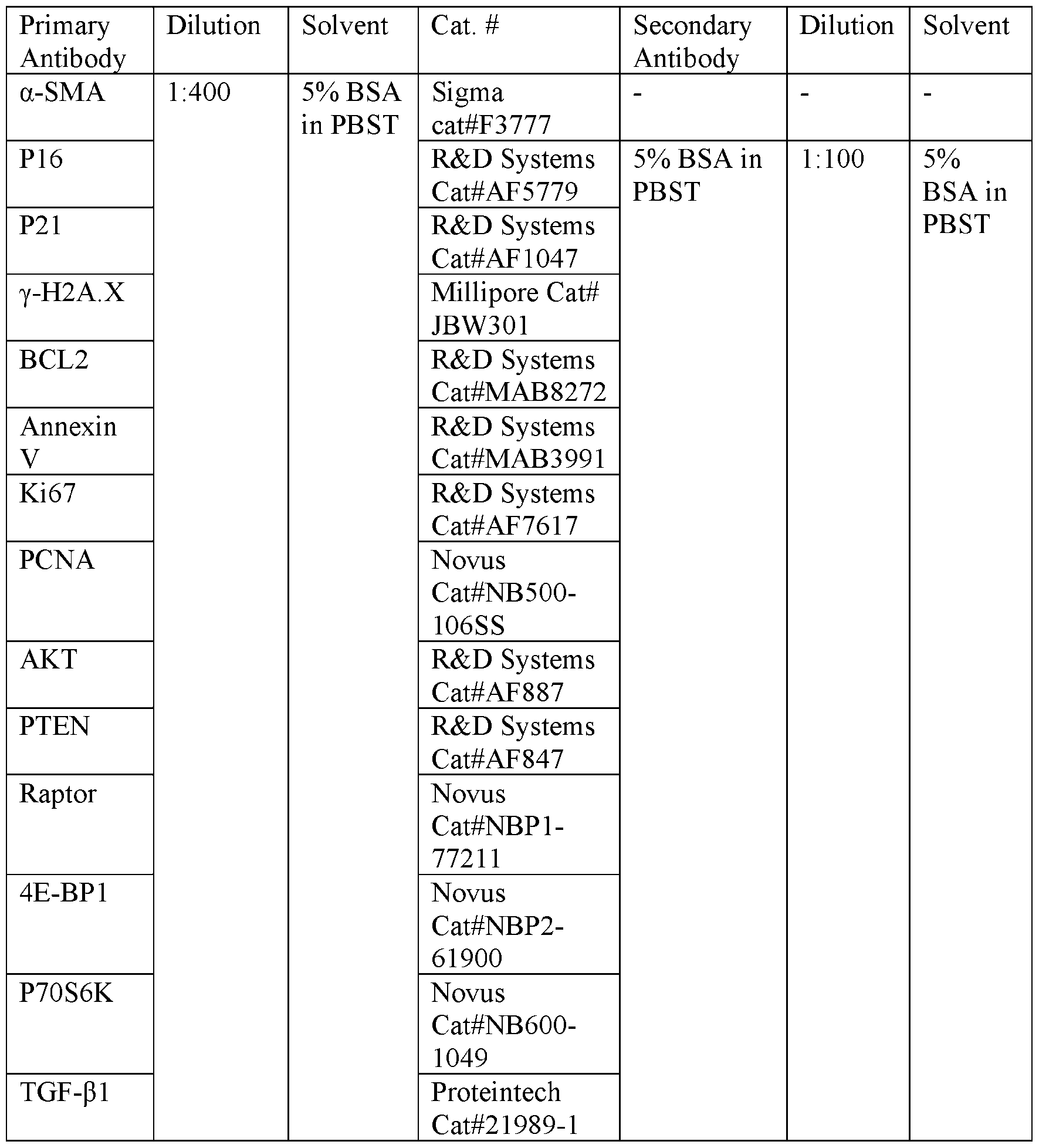
RNA Extraction from Collagen Type VIII Construct and Bulk RNA-Seq: The tendon construct (n = 6 samples per group with each sample consisting of 2 pooled constructs) were harvested from the hToC tissue component immediately following a 24- hr Rapamycin treatment exposure. Under sterile conditions, the vascular component was first removed from the tissue component using tweezers and exposing the tendon construct. The tendon constructs were then carefully removed from the tissue channel and
placed in a 1 .5 ml Eppendorf tube using tweezers. Optimal RNA yield was obtained by pooling two tendon constructs each holding a total of -57,000 cells (TC & tM(p). Collagenase I was used to degrade the collagen and release the cells from the construct by adding 500 pl of 1 mg/ml (215 units/mg) of collagenase I (Thermo Fisher, 17018029) diluted in X-VIVO™ 10 medium and stored at standard conditions for 45 min. Total RNA was isolated from released cells using the RNeasy Plus Micro Kit (Qiagen, 74134) per manufacturers recommendations. To isolate RNA from the EC monolayer, 100 pl of Lysis Buffer was added to the vascular component well for 10 min. The EC lysate was immediately processed following the manufacturers protocol. The RNA concentration was determined via NanoDrop 1000 spectrophotometer (NanoDrop, Wilmington, DE) and RNA quality assessed with the Agilent Bioanalyzer (Agilent, Santa Clara, CA). Messenger RNA isolation and next-generation RNA sequencing analysis was performed by the University of Rochester Genomics Core.
Data Availability: The RNA-seq raw and processed data were deposited in the Gene Expression Omnibus under accession GSE244543 and GSE246391.
Bulk Construct Analysis Techniques, Collagen Contraction Quantification: Images of tissue constructs were taken every 24 hrs over 7 days by placing the tissue channel component on a dissecting microscope (Nikon) to avoid image position variability. Images were converted to grayscale and analyzed in ImageJ for tissue area. a-SMA Quantification through Confocal Imaging: Z-stacks were processed in ImageJ by applying identical ROIs for each image>removing background fluorescence>selecting mean gray value>measure to each z-slice and averaging each slice value for each z-stack. Since the z-stacks were greater than 300 pm, all z-stack values were normalized to a FITC (a-SMA conjugated fluorophore) fluorescent decay curve prior to averaging to account for signal loss over depth of tissue. N = 3 devices per culture condition, and each device was imaged at 3 separate locations to account for bulk tissue variability.
Live-Stain Imaging and Quantification of Macrophage Transmigration in hToC: TC, tMy and cMy were live-stained prior to seeding into the hToC using the ViaFluor SE Cell Proliferation Kit (Biotium, 30068-T) and imaged at 3-, 24- or 72- hrs
respectively. For each image, a z-stack was taken every 10 minutes over 45 minutes starting ~50 pm on top of the porous membrane and 600 pm under the porous membrane to capture cMy migration through the EC monolayer and into the tissue channel component. To prevent cell death during imaging, the hToC was placed on an incubation stage at standard conditions for the entire imaging session. yH2A.X Quantification in Imaris: yH2A.X/DAPI stained tissue constructs were imaged using confocal imaging to create -300 pm z-stacks. Image stacks were quantified using the Imaris Spot-Spot colocalization module. Briefly, the size of each feature (Foci for yH2A.X and nucleus for DAPI) was measured prior to analysis of each image to define each channels Spot measurement. The Spot-Spot colocalization measurements were acquired using the shortest distance to spot calculation in the module. The spots were filtered using intensity to ensure only true colocalized spots were accounted for. N = 3 devices per culture condition, and each device was imaged at 3 separate locations to account for bulk tissue variability. The produced data was exported to Excel for further analysis.
Cellular alignment in Amira: Tissue channel constructs were fixed and stained with cytoskeletal actin as described above and imaged to obtain a 200 - 300 pm z-stacks. These images were analyzed using the commercially available algorithms in Amira software. Briefly, z-stacks were filtered on the actin channel by adding a median filter to represent full cell bodies, thresholded to remove non-specific stain using the Threshold. module and properly segmented out actin cellular bodies which did not colocalize with DAPI stain using the Smoothing. module and Remove Small Spots filter in Segmentation View. Help on Amira thresholding and segmentation methods can be found in Kenney et al [Kenney, H.M. et al., Bone Reports 16, 101167 (2022)]. Once images were filtered to represent only full cellular bodies, each cell was labeled using the Labels. module on a volume rendering of the z-stack to perform the OrientationLabelAnalysis. module, which was defined to report OrientationTheta, Volume 3D, and Index for labeled cellular body. N = 3 devices per culture condition, and each device was imaged at 3 separate locations to account for bulk tissue variability. The produced data was exported to Excel for further analysis.
The results are described herein. hToC design mimics the peritendinous fibrovascular scar niche of acute injury. The objective of the hToC design is to recreate the inflammatory and fibrotic processes in the peritendinous fibrovascular interface in a user-friendly and modular approach. The process of tendon healing is described as having three sequential and overlapping phases: 1) inflammatory, 2) fibroblastic/proliferative, and 3) remodeling, with each phase defined by the cellular and molecular constituents that predominate in the injury microenvironment [Gomez-Florit, M. et al., Advanced Drug Delivery Reviews 185, 114299 (2022); Graham, J.G. et al., Connect Tissue Res 60, 10-20 (2019)]. It is the duration and magnitude of the fibroblastic response that determines if the remodeling phase can resolve into a scarless tendon [Kumar, V. et al., Edn. Tenth edition (Jeremy Bowes, Elsevier; 2021); Khan, U. et al., J Hand Surg Br 21, 813-820 (1996)]. Prolonged exposure of fibroblastic cells to inflammatory signals prompts the excessive deposition of ECM resulting in a fibrovascular scar which can manifest as painful adhesions in patients [Gomez-Florit, M. et al., Advanced Drug Delivery Reviews 185, 114299 (2022); Demidova-Rice, T.N. et al., Adv Skin Wound Care 25, 304-314 (2012)]. While the healthy tendon is well-described as minimally vascularized, it is the neovascularization of the injury microenvironment that facilitates the arrival of immune cells and inflammatory factors that pace the healing process and determine if healing resolves as a scar or native tissue (Fig. 3 A). Interestingly, neovascularization is evident at adhesions when they occur but is limited to the proximal and distal ends of the injured tissue when healing occurs without adhesions [Potenza, A.D., J Bone Joint Surg Am 44-a, 49-64 (1962); Gelberman, R.H. et al., Hand 13, 120- 128 (1981); Richards, H.J., Injury 12, 1-12 (1980); Fenwick, S.A. et al., Arthritis Res 4, 252-260 (2002)]. These observations suggest that understanding the complex interactions between the vasculature and an injured tendon tissue may be key to identifying regulators that prevent the formation of peritendinous adhesions.
Fig. 3A through Fig. 3G depicts an exemplary design of the primary human Tendon-on-a-Chip (hToC) device according to aspects of the present invention. Fig. 3 A shows a schematic of injured tendon with histological image of fibrovascular scar depicts cellular and molecular interactions modeled in the hToC through vascular and tendon tissue interactions. Fig. 3B depicts an exploded view of the hToC device
comprising an optically transparent silicon porous membrane nestled on the acrylic vascular component which come together to form the vascular well component. Fig. 3C and Fig. 3D depict how the tissue channel and transparent imaging layer form the tissue channel component. In some embodiments, a chip is embedded in the vascular component comprising a Dual-Scale (DS) porous membrane with 5 pm pores (red outline) dispersed over a nanopororous (<100nm pores) background (green outline) where ECs are cultured to form a cohesive vascular barrier with developed junction proteins (VE-Cadherin (yellow). Fig. 3E depicts a tenocyte-embedded collagen construct placed in the tissue component where bulk contraction of the hydrogel is induced by anchoring through two horizontal bars (left). F-actin staining shows fibroblastic cell morphology of tenocytes embedded in the type I/III collagen hydrogel depicted with a z- projection of the construct. Fig. 3F depicts a modular design of the hToC device allows for reversible binding of vascular and tissue components through pressure-sensitive adhesive allowing for the combination of the vascular barrier in the vascular component to contact the tendon construct in the tissue channel. Fig. 3G shows VE- Cadherin/ Actin/D API staining show the vascular barrier (yellow) in the vascular component contacting the tendon construct (green) in the tissue channel.
To model the tendon-vascular interface, a two-component, vascular barrier model was customized [McCloskey, M.C. et al., bioRxiv, 2022.2003.2028.486095 (2022)] to accommodate a tendon tissue construct beneath the vascular barrier (Fig. 3B & Fig. 3C). Briefly, the hToC is composed of two mass-manufactured parts: 1) Component 1 is an acrylic block component featuring two fluidic ports for tissue channel access and a 100 pL well with a bottom ledge of exposed pressure sensitive adhesive (PSA) that enables sealing to a membrane ‘chip’ (Fig. 3D); 2) Component 2 features a fluidic channel of -65 pL total volume with horizontal anchors suspended on either end of the channel (See Fig. IM), to hold the tendon matrix in place as myofibroblasts contract. An exposable PSA layer on the open surface of the channel facilitates bonding to Component 1 (Fig. 3F) in assembly of the full hToC (Fig. 3C). The membrane ‘chip’ contains an ultrathin (-100 nm thick) free-standing, porous silicon nitride membrane patterned in a 700 pm x 2 mm window [Mossu, A. et al., Journal of Cerebral Blood Flow & Metabolism 39, 395-410 (2019); Salminen, A.T. et al., Small (Weinheim an der
Bergstrasse, Germany) 15, el 8041 11 -el 8041 11 (2019)]. The optically clear membrane features a dual-scale porosity with 5 pm pores superimposed on a nanoporous silicon nitride (NPN) background (Fig. 3D) [McCloskey, M.C. et al., bioRxiv, 2022.2003.2028.486095 (2022)]. The 5 pm pores provide portals for cell transmigration from the vascular to tendon component, while the nanopores (~60 nm diameter; ~ 15% porosity) allow for paracrine signaling by small molecule exchange throughout the membrane interface between components [Salminen, A.T. et al., Small (Weinheim an der Bergstrasse, Germany) 15, el80411 l-el804111 (2019)] (Fig. 3A).
Human umbilical vein endothelial cells (HUVECs) line the porous membrane to form the vascular interface (Fig. 3D) and human primary tendon fibroblasts (TCs), obtained from tenolysis surgery at the University of Rochester Medical Center, are embedded in a TeleCol®-3 collagen hydrogel and pipetted into component 2 for hydrogel crosslinking and culture (Fig. 3E). Given that TCs were sourced from human scar tissue, it is anticipated that this population exhibits a certain degree of fibrotic activation which is of value given that in the disclosed study, model injury was sought as a baseline state. The addition of tissue resident macrophages (tMcp) into the tissue construct and circulating monocytes into the vascular construct provides known immunomodulators of the inflammatory and fibrotic response native to peritendinous injury [Setten, E. et al., Nature communications 13, 6499-6499 (2022)].
The modular design of the hToC enables the independent culture of the vascular and tissue components before their integration as a composite tissue. This design feature is critical given that HUVECs achieve confluency in only 24 hours while it takes six days for polarization of the tMcp. By accommodating these disparate timelines, the hToC ensures that each component attains optimal functionality before the initiation of experiments, thus enhancing the fidelity and reliability of the model (See Fig. 2H). Assembly fixtures (Fig. 10, top) are used to combine component 1 to component 2 at the time of assembly to create the vascular-tendon interface (see Fig. 3G for imaging of interface) [McCloskey, M.C. et al., bioRxiv, 2022.2003.2028.486095 (2022)]. Modularity also enables end-point assays on each component, as the two components can also be detached following experiments (Fig. 3F). Finally, the components can be utilized individually by attaching a reservoir (See Fig. 10, bottom row) to either component 1 or
2, enabling the study of the vascular or tissue responses independently if desired (see Fig. 2H). The 9 mm x 18 mm footprint of the hToC was selected with plans for 96- well formatted arrays (Fig. 3C), and the device materials and thicknesses were selected to facilitate microscopy and image analysis of cellular and molecular interactions in both components.
Establishment of a model of human peritendinous injury: An ideal model of peritendinous fibrovascular scar formation should replicate the complex cascade of inflammatory, immunological, and fibroblastic responses that occur following injury. In this process, neutrophiles emerge as the initial responders to the injury site during the onset of inflammation. However, their concentration rapidly declines within hours, as macrophages assume the dominant immunological role through recruitment from the bone marrow, guided by chemokine gradients and adhesion molecules [Marsolais, D. et al., Journal of Orthopaedic Research 19, 1203-1209 (2001); Davies, L.C. et al., Nature Immunology 14, 986-995 (2013)]. This dynamic transition highlights the pivotal role of macrophages as key regulators at all stages of repair and fibrosis, capable of reversible polarization into distinct subtypes based on changes in cytokine exposure, ECM proteins, and local cellular environments [Nichols, A.E.C., Best, K.T. & Loiselle, A.E., Translational Research 209, 156-168 (2019); Wynn, T.A. & Vannella, K.M., Immunity 44, 450-462 (2016)]. Macrophages in their wound healing phenotype contribute significantly to fibrotic scar formation by secreting a multitude of growth factors, including TGF-bl33. Known as a potent driver of tissue fibrosis, endogenous and exogenous supply of TGF-bl have been demonstrated to promote myofibroblast differentiation, trigger secretion and deposition of ECM, induce senescent phenotypes, and facilitate the recruitment of immune cells [Nichols, A.E.C., Best, K.T. & Loiselle, A.E., Translational Research 209, 156-168 (2019); Eldred, J. & Wormstone, M., Acta Ophthalmologica 93, n/a-n/a (2015); Kim, K.K. et al., Cold Spring Harb Perspect Biol 10 (2018)]. These cascading effects lead to the persistence of an inflammatory response, ultimately culminating in a chronic state [Eldred, J. & Wormstone, M., Acta Ophthalmologica 93, n/a-n/a (2015); Kim, K.K. et al., Cold Spring Harb Perspect Biol 10 (2018); Vinals, F. & Pouyssegur, J., Molecular and Cellular Biology 21, 7218-7230
(2001); Farhat, Y.M. et al., JOURNAL OF CELLULAR PHYSIOLOGY 230, 318-326 (2015)].
Fig. 4A through Fig. 4D shows the fibrosis and inflammation validation in the hToC device. Fig. 4A shows a schematic of experimental workflow for an hToC device quad-culture assembly according to aspects of the present invention. Fig. 4B depicts the histology sections of quad-cultures showing fibroblastic morphology in tendon construct in the absence (left) and presence (right) of exogenous TGF-01 treatment. Sections were stained for expressed protein markers for myofibroblast activation (a- SMA), collagen-specific molecular chaperone (HSP47), apoptosis (BLC- 2), cellular proliferation (Ki67), cell-cycle arrest/DNA-damage signaling (P16), fibrosis regulator (TGF- 1), and mTOR pathway expression (pAKT, p4EBPl, pS6). Fig. 4C shows the effect of the porous membrane on the EC mono culture stained for leukocyte adhesion and activation markers VE-cadherin (green, column 1), CD31 (red, column 2), ICAM-1 (purple, column 3), and VCAM-1 (yellow, column 3) at (c, row 1) 24- and (c, row 2) 72-hours. Exogenous TGF-pi was added directly to the luminal EC surface and incubated for 72-hours and assessed with the same markers (c, row 3). These results were compared to the EC monolayer removed from a 72-hour cultured quad culture (c, row 4). Fig. 4D shows the supernatants of the quad-cultures sampled from the vascular and tissue sides, combined and sampled using an 8-panel Luminex® assay. The senescence associated secretory protein profile at 24- and 72-hours in the presence and absence of exogenous TGF-pi (N=3-4) were sampled. Ordinary one-way ANOVA used for comparison (*P < 0.05). Scale bar = 50 pm.
In the hToC, the peritendinous injury state was successfully modeled using a quad-culture. In this approach, embedded monocytes isolated from human peripheral blood donors are cocultured with TCs in TeleCol®-3 matrix and polarized into macrophages (tM<I>) over six days in the presence of monocyte-colony stimulating factor (M-CSF) (Fig. 4A). To mimic the arrival of circulating monocytes to the injury site through the vasculature, freshly isolated monocytes were introduced onto the vascular component, while TGF-bl-/+ treatment was directly administered to the tendon component (Fig. 4A). The two components were then assembled to create a quad culture system (TC/tMcp/EC/cMcp) and mark the initiation of the injury model, DO. The cellular
densities within the hToC were informed by the hypo-proliferative in vivo models of injured tendons one week after the insult, ensuring a fibroblast-to-macrophage ratio of 7: 1 and a cM(p density of 10,000 cells per 100 pL38. To minimize potential variability arising from serum in cell culture media, LONZA’s xvivo-10™ serum-free media was utilized for all cultures within the hToC model.
Comparisons between endogenous (TGF-01- quad culture) and exogenous (TGF-P1+ quad culture) treatment of TGF-pi in the hToC revealed the ability to achieve varying levels of disease progression. While most aspects of inflammation and fibrosis could be achieved through endogenous TGF-pi, it was observed that exogenous TGF-pi was necessary to induce cellular hyperproliferation and the development of senescent phenotypes in the tissue component. Additionally, immunocytochemical staining (ICC) of the tissue construct demonstrated significant expression of a-smooth muscle actin (a- SMA) + myofibroblasts when exposed to exogenous TGF-pi, a hallmark of fibrotic tissue. Constructs comprising both tM(p and TCs exhibited higher a-SMA expression compared to TC-only constructs and exhibited greater bulk tissue contraction (See Figs 11C through Fig. 1 IF). TC-only constructs treated with TGF-pi display a similar extent of contraction as TC/tM(p without exogenous TGF-pi. This indicates that tM(p secrete TGF-pi and/or other stimulatory molecules that drive tissue fibrosis without the need for exogenous factors (See Fig 1 IE & Fig. 1 IF). Quantification of activated TGF-pi in the cultures revealed that TCs alone are not effective in activating TGF-pi from its latent form, but that the inclusion of ECs and tMcp significantly increase endogenous TGF-pi levels within the culture (See Fig. 10A through Fig. 10D). Collectively this data indicates that the tissue model has some degree of fibrotic activity before assembling with the vascular component at DO, and that this may be further enhanced with the addition of the vasculature component even in the absence of exogenous TGF-p i and cM(p.
Despite the intrinsic tendency of the hToC to evolve into a fibrotic tissue, immunohistochemical (IHC) staining revealed that fibrotic disease markers, including active ECM deposition (HSP47) and cellular proliferation (Ki67), were more prominently observed in TGF-P1+ conditions (Fig. 4B). Notably, the activation of the phosphatidylinositol-3 -kinase (PI3K)/Akt and mammalian target of rapamycin (mTOR) signaling pathways, critical for cell growth and survival in both physiological and
pathological fibrotic conditions [Alenchery, R.G. et al., Journal of orthopaedic research (2023); Cong, XX. et al., STEM CELLS 36, 527-539 (2018)], was particularly pronounced in the TGF- pi+ culture. This suggests that excess TGF-pi signals the TC/tM(p culture into a more chronic disease state by increasing myofibroblast activation and pro-fibrotic stress signals. The hypothesized transition of a-SMA+ myofibroblasts into a chronic and senescent phenotype was substantiated by the upregulation of cellcycle arrest/DNA-damage marker pl6 and apoptotic marker BCL2 (Fig. 4B). Furthermore, examination of the senescent phenotype through the presence of the histone H2A variant H2AX phosphorylated on Ser 139 (yH2AX) revealed a significant increase in yH2AX foci within the tissue component upon treatment with exogenous TGF-pi. Interestingly, no significant differences were observed between TC-only and TC/tM(p tissue constructs, indicating that TCs predominantly contribute to DNA damage and subsequent senescent phenotype in the model. This senescent phenotype is well-known for its secretory role, releasing pro-fibrotic and inflammatory cytokines that perpetuate the injury response and contribute to progressive tissue degeneration. In the hToC, eight common [Kallenbach, J.G. et al., Sci Rep 12, 3026 (2022)] senescence-associated secretory proteins (SASP) were examined in the quad culture supernatant and observed an elevated profile that was sustained even at 72 hours (Fig. 4D). Remarkably, exogenous TGF-pi treatment rapidly induced the secretory profile within 24 hours and effectively maintained the presence of the complete SASP profile throughout the experimental period of the quad culture (See Fig. 12A & Fig. 12B).
The vascular component exhibited a robust activation of pro-inflammatory ECs following luminal exposure to TGF- pi for a duration of 72 hours (as depicted in Fig. 4C, rows 1-3). This activation was evidenced by the positive staining of key markers including intercellular adhesion molecule- 1 (ICAM-1) and vascular cell adhesion molecule-1 (VCAM-1) following luminal exposure to TGF-pi for a duration of 72 hours (as depicted in Fig. 4C, rows 1-3). Notably, even in the absence of TGF-pi, the EC monolayer exhibited activation after 72 hours. This may be due to the presence of 5 pm pores in the dual scale membrane which permits EC transmigration [Chung, H.H. et al., Lab on a chip 18, 1671-1689 (2018)]. In the quad culture model, the introduction of TGF - pi from the abluminal side resulted in a comparable and robust pro-inflammatory
activation (as shown in Fig 4C, row 4), thereby emphasizing the substantial inflammatory response within the vascular component.
To simulate the arrival of immune cells from the circulatory system, cM(p was introduced onto the vascular component at Do (Fig. 4A). Using live imaging (See Fig. 13A through Fig. 13G), we were able to demonstrate that cMcp transmigrated across the endothelial barrier and into the tissue component. cMcp were detectable into the tissue component within 3 hours after the assembly with the vascular component and their migration plateaued within 24 hours of quad culture (as shown in Fig. 13C & Fig. 13F). Moreover, the presence of tMcp in the tissue component enhanced the recruitment of cMcp into the tissue over 24-hours while the exogenous addition of TGF-pi did not have any significant effect in their migratory kinetics (See Fig. 13B & Fig. 13E). Thus, the transmigration of cMcp from the vasculature is driven by signaling cues developed from the secretory profiles of tissue resident cells.
To summarize, this study provides compelling evidence that the intricate cellular signaling network involving TCs, tMcp, cMcp, and ECs is primarily responsible for driving the secretory profile, including SASP, within the quad culture model. This profile serves as a marker of fibrotic disease on-chip and drives its progression. While the addition of exogenous TGF-bl in the hToC system was not essential for the development of inflammatory and fibrotic phenotypes observed within the quad culture, its presence led to hyperproliferation and a sustained and more mature SASP profile. For this reason, the TGF-bl quad culture model was used for validation studies and therapeutic testing.
Fig. 5A through Fig. 5F shows the results comparing tendon injury vs human tenolysis as measured with the disclosed hToC device. Fig. 5A, Fig. 5B and Fig. 5C show volcano plots detailing significant gene fold changes of - TGF-bl hToC v +TGF-b l hToC (Fig. 5A), Human Control v +TGF-bl hToC (Fig. 5B), and Human Control v Human Tenolysis (Fig. 5C) comparisons. Fig. 5D shows a dotplot graph signifying significantly regulated Reactome pathways commonly shared between the three comparisons. Fig. 5E and Fig. 5F show dissimilarity matrices showing all 34 KEGG pathways (Fig. 5E) and, 26 Reactome pathways shared between +TGF-bl hToC and Human Tenolysis changes from Human Control (Fig. 5F). It should be noted that N = 3
devices per condition representing 3 biological replicates. All DEG followed Padj < 0.05 and abs(Log2(FC)) > 1. hToC quad-culture shares key similarities with in vivo human tendon tenolysis: To further test the validity of the hToC quad culture +TGF- pi as an in vitro model of human peritendinous injury, bulk RNA-sequencing was performed, with the results compared to a published study by Wei Zheng et al, (2019) [Zheng, W. et al., J Adv Res 15, 49-58 (2019)] on human peritendinous fibrosis. Initially, the effect of TGF- i was assessed by analyzing the differential expression of TGF- 1+ compared to TGF- 31- quad cultures. The treatment of TGF-P1+ in the hToC model resulted in 462 downregulated genes and 304 upregulated genes (Fig. 5 A). Notably, the vascular component exhibited fewer than 70 differentially expressed genes (DEGs), indicating a specific effect of TGF-pi on the tissue-related aspects of the model. Furthermore, the gene expression profile of the in vitro disease model (TGF-P1+ quad culture hToC) was compared to healthy human tissue. This analysis revealed 1,011 downregulated genes and 597 upregulated genes (Fig. 5B). This comparison provides evidence that the quad culture hToC model mimics key molecular changes observed in human peritendinous fibrosis. To further support the validity of the model, published results of early-stage fibrotic peritendinous tissue samples (2-3 weeks after initial tendon injury) were compared to human control tendons (Human tenolysis v human control). This analysis identified a total of 1,668 downregulated genes and 1,101 upregulated genes (Fig. 5C). The differences of DEGs between the in vitro model and human tissue samples is similar in both cases (Fig. 5A, Fig. 5B, and Fig. 5C). This underscores that the hToC instigates profound alterations in the transcriptome when compared to human healthy tendon samples, and similar in magnitude to those observed in human tenolysis tissue.
To further support the analysis, GO, KEGG, and Reactome pathway enrichment analyses were performed based on the DEGs identified in the disclosed comparisons. The results revealed significant insights into the molecular pathways associated with peritendinous injury. First, GO dotplots generated for each comparison highlight a downregulation of pathways related to ECM organization in both human tenolysis and the hToC tissue component. Similarly, pathways associated with cell cycle regulation were upregulated in the vascular component of the hToC as well as in human
tenolysis (See Fig. 15B & Fig. 15C). A final dotplot comparison demonstrated shared pathways involving ECM interactions and interleukin signaling pathways across all three systems. These pathways play crucial roles in modulating ECM deposition, remodeling, as well as growth, differentiation, and activation during inflammatory and immune responses in fibrotic injury (Fig. 5D).
The overlapping Reactome (Fig. 5F) and KEGG (Fig. 5E) DEPs in the TGF-P1+ hToC versus human control and human tenolysis versus human control groups were analyzed through dissimilarity heatmaps. These plots assess overall similarity in pairwise comparisons, with darker colors indicating greater congruence and intensity of interaction between the genes. The KEGG pathways indicated higher similarity between the in vitro (+TGF-P1 hToC versus human control) and in vivo (human tenolysis versus human control) DEPs, particularly in the bottom quadrant (Fig. 5E). The Reactome DEPs showed slightly higher dissimilarity indices, but still a significant congruence (Fig. 5F) in key ECM, inflammation, interleukin signaling and the PI3K/AKT signaling pathways associated with peritendinous injury. Notably, the PI3K/AKT signaling pathway emerged as the most differentially expressed pathway in the disease node for the in vitro comparison (See Fig. 16A through Fig. 16D). Shown in Fig. 16A through Fig. 16D is the reactome pathway enrichment analysis of (Fig. 16A) human control v human tenolysis, and (Fig. 16C) -TGF- 1 hToC v +TGF- 1 hToC. Fig. 16A & Fig. 16C display pathways, described from left to right, top to bottom, as: Muscle Contraction, Immune System, chromatin organization, Metabolism of RNA, DNA Replication, Cell Cycle, Programmed Cell Death, Digestion and absorption, Circadian clock, Drug, ADME, DNA Repair, transport of small molecules, Reproduction, Cellular Responses to Stimuli, Developmental biology, Signal Transduction, Metabolism, Sensory Perception, Organelles biogenesis and maintenance, Autophagy, Neural system, hemostasis, Gene Expression (transcription), Disease, Metabolism of proteins, vesicle-mediated transport, cell-cell communication, for homo sapiens (gene names from liver) and homo sapiens, respectively. Additionally, gene set enrichment analysis (GSEA) revealed that mTOR signaling was downregulated in the in vivo comparison, likely due to the later stage of injury, while it remained notably upregulated in the in vitro model Interestingly, IHC staining performed on sections of human tendon tissue (Fig. 7E) revealed the
upregulation of u-SMA-positive cells as well as increased expression of downstream mTOR proteins 4E-BP1 and S6 upon injury. A further comparison of genome-wide overviews between in vitro and in vivo disease also demonstrated a strong correlation, particularly in immune system, signal transduction, and disease-related nodes. The shared genes between the in vivo and in vitro comparisons were explored using the matrisome- associated secreted factor protein database (http://matrisomeproject.mit.edu) which focused on proteins associated with extracellular matrix composition and remodeling [Shao, X. et al., Nucleic Acids Research 48, DI 136-D1144 (2019); Etich, J. et al., Int J Mol Sci 20 (2019)]. By analyzing the shared genes, potential markers of disease may be identified, and gain further insights into the consistency of the peritendinous injury response between the disclosed in vitro model and human samples. This analysis identified 33 genes that were shared between the conditions (See Table 1). These shared genes represent promising candidates to consider as markers for monitoring disease state. The consistency of gene expression and shared markers between the in vitro and human data validates the hToC as a tool for studying the molecular mechanisms of peritendinous injury and discovering potential therapeutic interventions. hToC as pharmacologic screening platform elucidates donor variability: The upregulation of the PI3K/AKT/mT0R signaling pathway in transcriptomic analysis is consistent with the previous observations of murine fibrotic pathophysiology [Alenchery, R.G. et al., Journal of orthopaedic research (2023)]. The PI3K/AKT/mT0R pathway has been previously associated with fibroblast proliferation, TGFbl- induced myofibroblast differentiation, and collagen production [Woodcock, H.V. et al., Nat Commun 10, 6 (2019)]. For these reasons, Rapamycin (RAPA) was investigated, a mTOR kinase inhibitor and FDA-approved drug [Baker, H. et al., J Antibiot (Tokyo) 31, 539-545 (1978); Mohamed, M.A. et al., Bioresour Bioprocess 9, 65 (2022)], to mitigate the development of advanced fibrosis in the hToC. It was predicted that the inhibition of the mTOR pathways with RAPA would block TGF-bl -induced fibrogenic effects including ECM deposition and myofibroblast differentiation similar to in vivo observations [Yoshizaki, A. et al., Arthritis Rheum 62, 2476-2487 (2010)]. To account for patient variability in the experimental design, three distinct cMcp donors were used.
Fig. 6A and Fig. 6B show the results for Rapamycin treatment in the disclosed hToC device. Fig. 6A is a schematic detailing an exemplary quad-culture assembly with 10 ng/ml Rapamycin insult onto the vascular component on DO, followed by a 24-hour culture. Fig. 6B shows the results for the secretome analysis in the hToC device vascular well and tissue component of 24-hour control (CTRL) and Rapamycin treatment (RAPA) through an 8-panel Luminex® assay for pro-inflammatory cytokines. Each dot represents mean of 3 technical replicates for a total of 3 cMcp donors conserved between control and treated conditions.
In these studies, 10 ng/ml of RAPA were added in xvivo-10™ media at the time of TGFbl+ and cMcp (DO) followed by culture for 24 hours (Fig. 6A). This method of drug application simulates the arrival of a single intravenous or oral dose at an injury site [Trepanier, D.J. et al., Clinical Biochemistry 31, 345- 351 (1998)]. To monitor changes in the inflammatory or fibrotic response to RAPA, the SASP profile was evaluated after 24 hours of treatment with an 8-panel Luminex® assay. While no significant changes were observed from control, secreted levels did vary between donors indicating the distinction of monocyte donor (cMcp) gives rise to a unique immune response for the tested cytokines (Fig. 6B).
Fig. 7A through Fig. 7E shows the staining results for mTOR activation and Rapamycin Treatment. Fig. 7A and Fig. 7C show the immunocytochemical staining of vascular monolayer (Fig. 7A) and tissue construct for phosphorylated mTOR proteins pAKT (white), p4EBPl (green), pS6 (orange) with F-actin counterstain (red) shows activation of pathway in the hToC device (Fig. 7C). Fig. 7B shows the immunocytochemical staining on the vascular side, intercellular junction protein VE- Cadherin (yellow), EC marker CD31 (red) and F-actin counterstain (green) show characterization of vascular component in the hToC. Fig. 7D shows the tissue construct staining for myofibroblast marker a-SMA and F-actin counterstain (red) depict myofibroblast changes upon RAPA treatment in the +TGF-blquad culture model. Fig. 7E shows as a comparison, human tissue sections of healthy (top row) and injured tendon (bottom row) are stained for downstream mTOR markers (left) and immune cell infiltration through vasculature (right). (All scale bars = 100 pm)
To examine the response to RAPA in detail, the inhibition of mTOR was directly monitored through ICC staining of upstream pAKT and downstream effector proteins p4E-BPl and pS6 in both the vascular and tissue components. Although p4E- BP1 expression did not significantly change with RAPA treatment in either component, expression of upstream pAKT and downstream pS6 did show some inhibition at the expressed protein level in the vascular component (Fig. 7A). The vascular monolayer, assessed by F-actin, VE-cadherin, and CD31 staining (Fig. 7B), showed a clear enhancement in vascular cohesiveness upon RAPA treatment. Specifically, the expression of junctional VE-cadherin was more evenly distributed in the monolayer, and noticeable gaps in the control monolayers were improved in the treated condition. This ability of RAPA to improve vasculature has been previously reported in neuroinfl ammatory diseases, in part by attenuating the inflammatory response and therefore improving vascular permeability [Towner, R.A. et al., Geroscience 43, 563-578 (2021); Lin, A.L. et al., J Cereb Blood Flow Metab 33, 1412-1421 (2013)]. The vascular impacts of RAPA in inflammatory diseases are overlooked, but the data encourage their further study.
RAPA treatment had impacts at the cellular and protein levels in both the vascular and tissue components. First, the localization of p4E-BPl was strikingly different between cell types, with high expression observed in the cytoplasm of fibroblastic-like cells and exclusive nuclear localization in ECs. This disparity suggests distinct phosphorylation kinetics in these two tissue components (Fig. 7A & Fig. 7C). Furthermore, the ECs displayed almost complete attenuation of pS6 expression, indicating that S6 is a more robust responder to RAPA treatment in ECs (Fig. 7A). In the tissue component, p4E-BPl expression was predominantly associated with round morphology cells rather than spread fibroblastic cells, suggesting that tMcp/cMcp, not TCs, contribute to its expression (Fig. 7C). The expression levels of phosphorylated pAKT, p4E-BPl, and pS6 did not exhibit obvious changes with RAPA treatment and the expression of a-SMA, a marker of myofibroblastic differentiation, significantly decreased and was accompanied by a loss of the fibroblastic morphology (Fig. 7D). While not a complete resolution of the fibrotic phenotype, these later data do indicate some reduction in overall fibrotic response. To ensure that RAPA treatment did not adversely affect cell
viability, a CCK-8 assay was conducted (see Fig. 17), revealing no negative impact on TCs within or outside of the hydrogel after 24 hours of treatment with 10 ng/ml RAPA (see Fig. 17). These results collectively demonstrate that RAPA treatment in the hToC model had substantial effects at the cellular and protein levels in both the vascular and tissue components.
Fig. 8A through Fig. 8F shows the results for the Genomic Response to Rapamycin Treatment in the disclosed hToC device. Fig. 8A is a volcano plot detailing significant gene fold changes of +TGF-bl hToC v +Rapamycin hToC comparison. Fig. 8B is a heatmap of significantly expressed secreted factor genes shared between Rapamycin treatment, +TGF-bl hToC, and human control, in both the vascular and tissue sides. Fig. 8C is a reactome dotplot. Fig. 8D shows a dissimilarity matrix of 13 differentially expressed pathways upon Rapamycin treatment. Fig. 8E and Fig. 8F show dotplots showing significant FC of mTOR, EC inflammatory adhesion molecules (Fig. 8E), and MMP genes (Fig. 8F). N = 3 biological replicates for each condition with each biological replicate comprising 3 technical replicates.
Rapamycin initial pathways of tissue repair: The impact of RAPA on the regulation of the inflammatory and fibrotic response was investigated through bulk RNA- seq of the TGF-bl+ quad culture (‘untreated’) and RAPA treated hToC. Volcano plots comparing treated to untreated samples revealed significant changes in gene expression, with 994 downregulated and 2,170 upregulated DEGs (Fig. 8A). Interestingly, few genes were attributed to changes from the tissue component, indicating that RAPA had little effect on the tissue, while the vascular component produced a significant response. This disparity in response can potentially be attributed to the introduction of RAPA through the vascular component so that it will first interact with ECs/cMcp and must transit the vascular barrier to reach the underlying tissue. The improved vascular integrity resulting from RAPA treatment might further limit its diffusion into the tissue component, thereby reducing effects on TC and tMcp. Previous studies have demonstrated the cytoprotective properties of RAPA in in vitro models of ischemia, suggesting its protective effect against cell damage via autophagy [Gabryel, B., Archives of Medical Science - Civilization Diseases 5, 14-21 (2020)]. Although the hToC is not a model of ischemia, it depicts vascular damage through TGF-bl+ which decreases vascular barrier integrity and
induces angiogenesis [Lebrin, F. et al., Cardiovasc Res 65, 599-608 (2005)]. It is important to note that RAPA was administered as a single dose over 24 hours in this study, which differs from in vivo administration that typically involves multiple doses over extended periods [Trepanier, D.J. et al., Clinical Biochemistry 31, 345- 351 (1998)].
A second transcript analysis of the combined vascular and tissue components revealed that approximately 26% (92 out of 344) of the matrisome- associated secreted factors in the matrisomeDB project database [Shao, X. et al., Nucleic Acids Research 48, DI 136-D1144 (2019)] were detectable under RAPA treatment in the hToC. Approximately 23% (40 out of 171) of the core matrisome proteins involved in collagen synthesis and degradation were detected, indicating the presence of key regulators of the ECM in fibrotic disease and resolution (see Fig. 18, Fig. 19A, and Fig. 19B). A subset of 12 genes showed differential expression between untreated and RAPA treated conditions (Fig. 8B). These transcripts and their protein products are potential candidates for monitoring disease progression and response to therapy.
Next, using a reactome pathway enrichment analysis, 13 DE pathways (DEP) were identified following treatment with RAPA. Particularly notable are DEPs that are associated with immunoregulatory interactions between lymphoid and nonlymphoid cells including selectin and integrin interactions; and various markers of vascular inflammation (Fig. 6C, Fig. 6D). Notably, the expression of AKT1 and RPS6 did not change significantly after RAPA treatment despite the clear effects seen at the protein level by ICC (Fig. 5A through Fig. 5F). On the other hand, the gene encoding for the translation initiating protein EIF4EBP1 exhibited a fold change (FC) of -0.84. Clearly RAPA exerts influence through both translational and post-translational mechanisms in the hToC.
Transcripts of essential ECM deposition proteins such as COL1A1, COL3A1, ACTA2, were significantly upregulated after RAPA treatment. This indicates a potential promotion of ECM remodeling and tissue repair (Fig. 8E). Additionally, matrix metalloproteinases (MMPs) including MMP13 (FC = 14.2), known for their involvement in ECM remodeling, showed increased expression. Importantly, the downregulation of EC adhesion marker ICAM1 (Fig. 6E) indicates that the activation of ECs is suppressed
by RAPA. This is consistent with enhanced barrier function suggested by ICC [Etich, J. et al., Int J Mol Sci 20 (2019)].
Fig. 9 depicts a workflow for MPS disease models in therapeutic discovery. MPS offer a powerful platform for modeling disease by faithfully capturing the cellular, matrix, and environmental cues that shape the desired microenvironment. By integrating these key elements, MPS models enable a deeper understanding of disease pathogenesis, as they can be cross referenced with existing in vivo data. This integration of in vivo and in vitro approaches holds tremendous potential for developing personalized and effective therapeutics tailored to the specific needs of individual patients.
The data presented in this study provide strong validation for the utilization of the hToC as a disease model for fibrovascular injury. Moreover, the importance of building upon existing work in animal or human models to guide the development of relevant and translational disease models should be emphasized (Fig. 9). Leveraging the knowledge gained from these models is essential, especially in cases where the pathophysiology in humans is not yet fully understood. Animal models can provide valuable reference metrics that can be incorporated into desired MPS platforms, ensuring their fidelity and relevance to the field.
The hToC model, by incorporating key elements from both animal and human studies, bridges the gap between preclinical and clinical research. The hToC model enables researchers to investigate and understand the complex mechanisms underlying fibrovascular injury and explore potential therapeutic interventions with a patient-specific approach. This advancement has the potential to revolutionize drug development and treatment strategies by tailoring interventions to individual patients' needs.
Various improvements for the hToC have been identified to enhance its physiological relevance and utility in therapeutic dosing. One key improvement is the introduction of recirculating physiological fluid flow, which allows for clearance of accumulated waste materials and enable ECs to undergo shear priming and physiological conditioning. This integration of fluid flow also facilitates interactions between ECs and circulating immune cells, further enhancing the model’s relevance. However, it should be noted that the incorporation of recirculating flow increases the working volume of the
medium, making it challenging to monitor the culture’s secreted factors. Addressing this limitation is achieved through the incorporation of real-time sensing technology into MPS, enabling the monitoring of secretory profdes and providing valuable information on disease progression and therapeutic efficacy [Cognetti, J.S. et al., Lab on a chip 23, 239-225 (2023)].
Considering the dynamic nature of tendons and their role in mechanical energy transfer, the incorporation of mechanical actuation within the tendon tissue component would be beneficial. This would enable the assessment of physical therapy metrics in conjunction with biological treatments, leading to improved patient outcomes [Killian, M.L. et al., Journal of Shoulder and Elbow Surgery 21, 228-237 (2012)]. While the use of primary cells is highly accessible, it introduces epigenetic effects into the model, as highlighted by the varying SASP response levels observed with different cMcp donors. These variable and difficult-to-control effects make primary cells impractical for clinical trial therapeutic screening. To overcome this challenge, improved models of peritendinous injury should leverage induced pluripotent stem cells (iPSCs) to accurately model and infer outcomes of specific patients and populations [Sayed, N., Liu, C. & Wu, J.C., J Am Coll Cardiol 67, 2161-2176 (2016); Ajalik, R.E. et al., Frontiers in Bioengineering and Biotechnology 10 (2022)]. iPSCs offer the advantage of capturing patient-specific characteristics, allowing for a more precise and personalized approach to therapeutic screening.
In conclusion, these data presented demonstrate the capability of the hToC to effectively induce cellular responses that correlate with the onset of peritendinous injury in human tendons. While the in vitro analysis may not fully replicate the complexities of the in vivo wound bed, several valuable cellular, molecular, and genomic components of peritendinous injury have been identified within the hToC. This model holds great potential for advancing the world’s understanding of fibrovascular injuries and their associated pathophysiology and, when implemented in a higher throughput version, could serve as a valuable tool for screening anti-fibrotic candidates. This would accelerate the discovery process, potentially reducing the reliance on animal models in studying tendon and other fibrotic diseases affecting organs such as the lung [Woodcock, H.V. et al., Nat Commun 10, 6 (2019)], heart [Khan, R. & Sheppard, R., Immunology
118, 10-24 (2006)], liver [Dataller, R. & Brenner, D A. Liver fibrosis. J Clin Invest 115, 209-218 (2005)] and cancer [Piersma, B. et al., Biochim Biophys Acta Rev Cancer 1873, 188356 (2020)]. Further information may be found in Ajalik et al., [Ajalik RE, Linares I, Alenchery RG, et al. Human Tendon-on-a-Chip for Modeling the Myofibroblast Microenvironment in Peritendinous Fibrosis. Adv Healthc Mater. Published online November 15, 2024. doi: 10.1002/adhm.202403116]
The disclosures of each and every patent, patent application, and publication cited herein are hereby each incorporated herein by reference in their entirety. While this invention has been disclosed with reference to specific embodiments, it is apparent that other embodiments and variations of this invention may be devised by others skilled in the art without departing from the true spirit and scope of the invention. The appended claims are intended to be construed to include all such embodiments and equivalent variations.
Claims
1. A microphysiological device; comprising: a first component comprising a frame having at least one opening passing through the frame forming a first interior region, wherein the first interior region comprises a tissue construct; a second component comprising a frame having at least a first opening passing through the frame forming a second interior region; a holder comprising a frame having at least one opening passing through the frame forming a third interior region, and a membrane positioned across the opening comprising at least one a cellular monolayer layered thereon; wherein the holder is removably positioned within the second interior region of the second component, and the first component and second component are fixedly and removably attached thereby fluidly connecting the first, second, and third interior regions.
2. The device of claim 1, further comprising a base layer having a top and bottom surface and a thickness therebetween, wherein the base layer fixedly and removably attaches to the first component.
3. The device of claim 1, wherein the second component comprises a second and third opening passing through the frame.
4. The device of claim 1, wherein the first component comprises first and second crossmembers spanning the opening in the frame, thereby dividing the first interior region into a first end region, middle region, and second end region.
5. The device of claim 1, further comprising one or more gaskets positioned between the first and second components.
6. The device of claim 1, wherein the tissue construct comprises one or more polymers or hydrogels.
7. The device of claim 1, wherein the tissue construct comprises one or more cells comprising tendon fibroblasts, tenoblasts, or tenocytes.
8. The device of claim 7, wherein the one or more cells of the tissue construct further comprise macrophages.
9. The device of claim 1, wherein the cellular monolayer comprises one or more cells comprising endothelial cells or epithelial cells.
10. The device of claim 9, wherein the one or more cells of the cellular monolayer further comprise monocytes.
11. The device of claim 9, wherein one or more support cells are seeded on the opposite side of the membrane from the cellular monolayer, the one or more support cells selected from any of pericyte cells, fibroblast cells, mesenchymal cells or stellate cells.
12. A microphysiological system, comprising: the device of claim 1; a third component comprising a frame having at least a one opening passing through the frame forming a fourth interior region; and an assembly jig.
13. The system of claim 12, further comprising: one or more sensors positioned within the first component or second component, each sensor fluidly connected with the first interior region, or the second interior region, respectively.
14. The system of claim 13, further comprising: a computer electronically and communicatively connected to the one or more sensors.
15. A method for a microphysiological system, comprising the steps of: providing the microphysiological system of claim 12; culturing one or more cells of a first cell type in the first interior region for a first period of time; culturing one or more cells of a second cell type in the second interior region for a second period of time; and combining the first component and the second component and co-culturing all the cells together for a third period of time.
16. The method of claim 15, further comprising the step of treating the first interior region or the second interior region.
17. The method of claim 16, wherein treating the first interior region or the second interior region comprises administering at least one agent.
18. The method of claim 17, wherein the at least one agent comprises any of small molecules, nucleic acids, peptides, siRNAs, shRNAs, miRNAs, ribozymes, antisense nucleic acids, antagonists, inhibitors, agonists, partial agonists, inverse agonists, aptamers, peptidomimetics, viruses, bacteria, cells, or any combination thereof. In some embodiments, the one or more agents are anti-fibrotic agents, anti-cancer therapies, anti-cancer drugs, anti-viral drugs, anti-microbial drugs, anti-arthritic drugs, or anti-fibrotic drugs.
19. The method of claim 15, further comprising separating the first component and the second component and analyzing the components individually.
20. The method of claim 15, wherein the first period of time ranges between 1 hour and 7 days, and the second period of time ranges between 1 hour and 7 days.
Applications Claiming Priority (2)
| Application Number | Priority Date | Filing Date | Title |
|---|---|---|---|
| US202363609826P | 2023-12-13 | 2023-12-13 | |
| US63/609,826 | 2023-12-13 |
Publications (2)
| Publication Number | Publication Date |
|---|---|
| WO2025129003A1 true WO2025129003A1 (en) | 2025-06-19 |
| WO2025129003A9 WO2025129003A9 (en) | 2025-11-13 |
Family
ID=94322943
Family Applications (1)
| Application Number | Title | Priority Date | Filing Date |
|---|---|---|---|
| PCT/US2024/060041 Pending WO2025129003A1 (en) | 2023-12-13 | 2024-12-13 | Microphysiological device, system and method |
Country Status (1)
| Country | Link |
|---|---|
| WO (1) | WO2025129003A1 (en) |
Citations (3)
| Publication number | Priority date | Publication date | Assignee | Title |
|---|---|---|---|---|
| US20170218321A1 (en) * | 2014-10-29 | 2017-08-03 | Corning Incorporated | Cell culture insert |
| US20210079330A1 (en) * | 2014-03-21 | 2021-03-18 | Iontox, Llc | Dynamic multi organ plate |
| WO2022099161A1 (en) * | 2020-11-06 | 2022-05-12 | University Of Rochester | Devices and methods for monitoring cells, tissues, or organs-on-a-chip |
-
2024
- 2024-12-13 WO PCT/US2024/060041 patent/WO2025129003A1/en active Pending
Patent Citations (3)
| Publication number | Priority date | Publication date | Assignee | Title |
|---|---|---|---|---|
| US20210079330A1 (en) * | 2014-03-21 | 2021-03-18 | Iontox, Llc | Dynamic multi organ plate |
| US20170218321A1 (en) * | 2014-10-29 | 2017-08-03 | Corning Incorporated | Cell culture insert |
| WO2022099161A1 (en) * | 2020-11-06 | 2022-05-12 | University Of Rochester | Devices and methods for monitoring cells, tissues, or organs-on-a-chip |
Non-Patent Citations (75)
| Title |
|---|
| A. S HOFFMAN, ADV. DRUG DEL. REV, vol. 43, 2002, pages 3 - 12 |
| AJALIK RELINARES IALENCHERY RG ET AL.: "Human Tendon-on-a-Chip for Modeling the Myofibroblast Microenvironment in Peritendinous Fibrosis", ADV HEALTHC MATER, 15 November 2024 (2024-11-15) |
| AJALIK, R.E. ET AL., FRONTIERS IN BIOENGINEERING AND BIOTECHNOLOGY, vol. 10, 2022 |
| ALENCHERY, R.G. ET AL., JOURNAL OF ORTHOPAEDIC RESEARCH, 2023 |
| BAKER, H. ET AL., J ANTIBIOT (TOKYO, vol. 31, 1978, pages 539 - 545 |
| BARRÉ-SINOUSSI, F.MONTAGUTELLI, X., FUTURE SCI OA, vol. 1, 2015, pages 63 |
| BATALLER, R.BRENNER, D.A.: "Liver fibrosis", J CLIN INVEST, vol. 115, 2005, pages 209 - 218, XP002450194, DOI: 10.1172/JCI200524282 |
| BRANNON-PEPPAS: "Preparation and Characterization of Cross-linked Hydrophilic Networks in Absorbent Polymer Technology", 1990, ELSEVIER, pages: 45 - 66 |
| CHEN, L. ET AL., ONCOTARGET, vol. 9, 2017, pages 7204 - 7218 |
| CHUNG, H.H. ET AL., LAB ON A CHIP, vol. 18, 2018, pages 1671 - 1689 |
| COGNETTI, J.S. ET AL., LAB ON A CHIP, vol. 23, 2023, pages 239 - 225 |
| CONG, X.X. ET AL., STEM CELLS, vol. 36, 2018, pages 527 - 539 |
| DAVIES, L.C. ET AL., NATURE IMMUNOLOGY, vol. 14, 2013, pages 986 - 995 |
| DEMIDOVA-RICE, T.N. ET AL., ADV SKIN WOUND CARE, vol. 25, 2012, pages 304 - 314 |
| DJUDJAJ, S.BOOR, P., MOL ASPECTS MED, vol. 65, 2019, pages 16 - 36 |
| ELDRED, J.WORMSTONE, M., ACTA OPHTHALMOLOGICA, vol. 93, 2015, pages 93 |
| ETICH, J. ET AL., INT J MOL SCI, vol. 20, 2019, pages 20 |
| FARHAT, Y.M. ET AL., JOURNAL OF CELLULAR PHYSIOLOGY, vol. 230, 2015, pages 318 - 326 |
| FARHAT, Y.M. ET AL., PLOS ONE, vol. 7, 2012, pages 51411 |
| FAROOQI, H.M.U. ET AL., NANO CONVERG, vol. 8, 2021, pages 3 |
| FENWICK, S.A. ET AL., ARTHRITIS RES, vol. 4, 2002, pages 252 - 260 |
| GABRYEL, B., ARCHIVES OF MEDICAL SCIENCE - CIVILIZATION DISEASES, vol. 5, 2020, pages 14 - 21 |
| GELBERMAN, R.H. ET AL., HAND, vol. 13, 1981, pages 120 - 128 |
| GOMEZ-FLORIT, M. ET AL., ADVANCED DRUG DELIVERY REVIEWS, vol. 185, 2022, pages 114299 |
| GRAHAM, J.G. ET AL., CONNECT TISSUE RES, vol. 60, 2019, pages 10 - 20 |
| HEUNGSOO SHIN, BIOMATERIALS, vol. 24, 2003, pages 4353 - 4364 |
| HILL-WEST ET AL., PROC. NATL. ACAD. SCI. USA, vol. 91, 1994, pages 5967 - 5971 |
| HUH, D. ET AL., SCIENCE, vol. 328, 2010, pages 1662 - 1668 |
| HWANG ET AL., TISSUE ENG, vol. 12, 2006, pages 2695 - 706 |
| IFKOVITSBURDICK, TISSUE ENG, vol. 13, no. 10, 2007, pages 2369 - 85 |
| IMTIYAZ HOSSAIN, M.CHRISTOPHER MILNE, D.MPH, JD, CLINICAL THERAPEUTICS, vol. 40, 2018, pages 1066 - 1075 |
| KALLENBACH, J.G. ET AL., SCI REP, vol. 12, 2022, pages 3026 |
| KENNEY, H.M. ET AL., BONE REPORTS, vol. 16, 2022, pages 101167 |
| KHAN, R.SHEPPARD, R., IMMUNOLOGY, vol. 118, 2006, pages 10 - 24 |
| KHAN, U. ET AL., J HAND SURG BR, vol. 21, 1996, pages 813 - 820 |
| KILLIAN, M.L. ET AL., JOURNAL OF SHOULDER AND ELBOW SURGERY, vol. 21, 2012, pages 228 - 237 |
| KIM, K.K. ET AL., COLD SPRING HARB PERSPECT BIOL, vol. 10, 2018 |
| KOSTRZEWSKI, T. ET AL., COMMUN BIOL, vol. 4, 2021, pages 1080 |
| LEBRIN, F. ET AL., CARDIOVASC RES, vol. 65, 2005, pages 599 - 608 |
| LIFENET HEALTH LIFESCIENCES: "Microphysiological System", 1 August 2022 (2022-08-01), pages 1 - 2, XP093259904, Retrieved from the Internet <URL:https://lnhlifesciences.org/microphysiological-system> [retrieved on 20250316] * |
| LIN, A.L. ET AL., J CEREB BLOOD FLOW METAB, vol. 33, 2013, pages 1412 - 1421 |
| MARSOLAIS, D. ET AL., JOURNAL OF ORTHOPAEDIC RESEARCH, vol. 19, 2001, pages 1203 - 1209 |
| MCCLOSKEY MOLLY C. ET AL: "The Modular SiM: A Mass Produced, Rapidly Assembled, and Reconfigurable Platform for the Study of Barrier Tissue Models In Vitro", ADVANCED HEALTHCARE MATERIALS, vol. 11, no. 18, 2200804, 15 August 2022 (2022-08-15), pages 1 - 16, XP093259727, ISSN: 2192-2640, Retrieved from the Internet <URL:https://onlinelibrary.wiley.com/doi/full-xml/10.1002/adhm.202200804> DOI: 10.1002/adhm.202200804 * |
| MCCLOSKEY, M.C. ET AL., BIORXIV, 2022 |
| MOHAMED, M.A. ET AL., BIORESOUR BIOPROCESS, vol. 9, 2022, pages 65 |
| MOON, A.M. ET AL., CLIN GASTROENTEROL HEPATOL, vol. 18, 2020, pages 2650 - 2666 |
| MOSSU, A. ET AL., JOURNAL OF CEREBRAL BLOOD FLOW & METABOLISM, vol. 39, 2019, pages 395 - 410 |
| NGUYENWEST, BIOMATERIALS, vol. 23, no. 22, 2002, pages 4307 - 14 |
| NICHOLS, A.E.C.BEST, K.T.LOISELLE, A.E., TRANSLATIONAL RESEARCH, vol. 209, 2019, pages 156 - 168 |
| NIE, D. ET AL., STEM CELLS INTERNATIONAL, vol. 2021, 2021, pages 6638249 - 6638249 |
| NOAH, A.C. ET AL., J APPL PHYSIOL, vol. 128, 1985, pages 473 - 482 |
| OGDEN, H.L. ET AL., MICROMACHINES, 2021, pages 12 |
| PEPPASMIKOS: "Preparation Methods and Structure of Hydrogels in Hydrogels in Medicine and Pharmacy", 1986, CRC PRESS, pages: 1 - 27 |
| PIERSMA, B. ET AL., BIOCHIM BIOPHYS ACTA REV CANCER, vol. 1873, 2020, pages 188356 |
| POTENZA, A.D., J BONE JOINT SURG AM, vol. 44, 1962, pages 49 - 64 |
| RICHARDS, H.J., INJURY, vol. 12, 1980, pages 1 - 12 |
| SAFIRI, S. ET AL., ARTHRITIS & RHEUMATOLOGY, vol. 73, 2021, pages 702 - 714 |
| SALMINEN, A.T. ET AL., SMALL, vol. 15, 2019, pages 1804111 |
| SAYED, N.LIU, C.WU, J.C., J AM COLL CARDIOL, vol. 67, 2016, pages 2161 - 2176 |
| SCHOENENBERGER, A.D. ET AL., BIOMATERIALS, vol. 249, 2020, pages 120034 |
| SETTEN, E. ET AL., NATURE COMMUNICATIONS, vol. 13, 2022, pages 6499 - 6499 |
| SHAO, X. ET AL., NUCLEIC ACIDS RESEARCH, vol. 48, 2019, pages 1136 - 1144 |
| SHEN, J.X. ET AL., CHEM RES TOXICOL, vol. 33, 2020, pages 38 - 60 |
| STAUBER, T. ET AL., ADVANCED HEALTHCARE MATERIALS, vol. 10, 2021, pages 2100741 |
| STOLK, M. ET AL., SCIENTIFIC REPORTS, vol. 7, 2017, pages 9801 |
| TOEPKE, M.W.BEEBE, D.J.: "PDMS absorption of small molecules and consequences in microfluidic applications", LAB ON A CHIP, vol. 6, 2006, pages 1484 - 1486 |
| TOWNER, R.A. ET AL., GEROSCIENCE, vol. 43, 2021, pages 563 - 578 |
| TREPANIER, D.J. ET AL., CLINICAL BIOCHEMISTRY, vol. 31, 1998, pages 345 - 351 |
| VINALS, F.POUYSSEGUR, J., MOLECULAR AND CELLULAR BIOLOGY, vol. 21, 2001, pages 7218 - 7230 |
| W. E. HENNINKC. F. VAN NOSTRUM, ADV. DRUG DEL. REV., vol. 43, 2002, pages 13 - 12 |
| WOODCOCK, H.V. ET AL., NAT COMMUN, vol. 10, 2019, pages 6 |
| WYNN, T.A.RAMALINGAM, T.R., NATURE MEDICINE, vol. 18, 2012, pages 1028 - 1040 |
| WYNN, T.A.VANNELLA, K.M., IMMUNITY, vol. 44, 2016, pages 450 - 462 |
| YOSHIZAKI, A. ET AL., ARTHRITIS RHEUM, vol. 62, 2010, pages 2476 - 2487 |
| ZHENG, W. ET AL., J ADV RES, vol. 15, 2019, pages 49 - 58 |
Also Published As
| Publication number | Publication date |
|---|---|
| WO2025129003A9 (en) | 2025-11-13 |
Similar Documents
| Publication | Publication Date | Title |
|---|---|---|
| US20230159899A1 (en) | Devices and methods for simulating a function of liver tissue | |
| Jain et al. | Spatial confinement downsizes the inflammatory response of macrophages | |
| Musah et al. | Mature induced-pluripotent-stem-cell-derived human podocytes reconstitute kidney glomerular-capillary-wall function on a chip | |
| Sundarakrishnan et al. | Bioengineered in vitro tissue model of fibroblast activation for modeling pulmonary fibrosis | |
| Lacombe et al. | Plant-based scaffolds modify cellular response to drug and radiation exposure compared to standard cell culture models | |
| Zhong et al. | Human immune organoids to decode B cell response in healthy donors and patients with lymphoma | |
| Kolanko et al. | The evolution of in vitro models of lung fibrosis: promising prospects for drug discovery | |
| Donaldson et al. | Photocrosslinkable gelatin hydrogels modulate the production of the major pro-inflammatory cytokine, TNF-α, by human mononuclear cells | |
| Hatch et al. | Engineered alginate hydrogels for effective microfluidic capture and release of endothelial progenitor cells from whole blood | |
| Shin et al. | Functional spheroid organization of human salivary gland cells cultured on hydrogel-micropatterned nanofibrous microwells | |
| JP2018505691A (en) | Devices, platforms and assays for assessing cells | |
| WO2018102201A1 (en) | In vitro epithelial models comprising lamina propria-derived cells | |
| Ismayilzada et al. | Skin-on-a-chip technologies towards clinical translation and commercialization | |
| Jang et al. | Advanced in vitro three-dimensional skin models of atopic dermatitis | |
| Caires et al. | A co‐culture system with three different primary human cell populations reveals that biomaterials and MSC modulate macrophage‐driven fibroblast recruitment | |
| Corum et al. | Using microcontact printing of fibrinogen to control surface-induced platelet adhesion and activation | |
| Peters et al. | Umbilical cord blood-derived mononuclear cells exhibit pericyte-like phenotype and support network formation of endothelial progenitor cells in vitro | |
| Ajalik et al. | Human Tendon‐on‐a‐Chip for Modeling the Myofibroblast Microenvironment in Peritendinous Fibrosis | |
| Gijzen et al. | An immunocompetent human kidney on-a-chip model to study renal inflammation and immune-mediated injury | |
| Yuan et al. | A pulmonary vascular model from endothelialized whole organ scaffolds | |
| Serrano et al. | On-chip engineered human lymphatic microvasculature for physio-/pathological transport phenomena studies | |
| Awad et al. | Human tendon-on-a-chip for modeling vascular inflammatory fibrosis | |
| US20240198337A1 (en) | Bone Marrow on a Chip | |
| Williams et al. | Enabling mesenchymal stromal cell immunomodulatory analysis using scalable platforms | |
| Takahashi et al. | 3D in vitro co-culture disc for spatiotemporal image analysis of cancer–stromal cell interaction |
Legal Events
| Date | Code | Title | Description |
|---|---|---|---|
| 121 | Ep: the epo has been informed by wipo that ep was designated in this application |
Ref document number: 24841346 Country of ref document: EP Kind code of ref document: A1 |