WO2025121150A1 - プリフォームはんだ及びその製造方法、並びにはんだ継手の製造方法 - Google Patents
プリフォームはんだ及びその製造方法、並びにはんだ継手の製造方法 Download PDFInfo
- Publication number
- WO2025121150A1 WO2025121150A1 PCT/JP2024/041303 JP2024041303W WO2025121150A1 WO 2025121150 A1 WO2025121150 A1 WO 2025121150A1 JP 2024041303 W JP2024041303 W JP 2024041303W WO 2025121150 A1 WO2025121150 A1 WO 2025121150A1
- Authority
- WO
- WIPO (PCT)
- Prior art keywords
- metal
- mass
- phase
- content
- metal powder
- Prior art date
- Legal status (The legal status is an assumption and is not a legal conclusion. Google has not performed a legal analysis and makes no representation as to the accuracy of the status listed.)
- Pending
Links
Images


Classifications
-
- B—PERFORMING OPERATIONS; TRANSPORTING
- B23—MACHINE TOOLS; METAL-WORKING NOT OTHERWISE PROVIDED FOR
- B23K—SOLDERING OR UNSOLDERING; WELDING; CLADDING OR PLATING BY SOLDERING OR WELDING; CUTTING BY APPLYING HEAT LOCALLY, e.g. FLAME CUTTING; WORKING BY LASER BEAM
- B23K35/00—Rods, electrodes, materials, or media, for use in soldering, welding, or cutting
- B23K35/02—Rods, electrodes, materials, or media, for use in soldering, welding, or cutting characterised by mechanical features, e.g. shape
- B23K35/0205—Non-consumable electrodes; C-electrodes
-
- B—PERFORMING OPERATIONS; TRANSPORTING
- B23—MACHINE TOOLS; METAL-WORKING NOT OTHERWISE PROVIDED FOR
- B23K—SOLDERING OR UNSOLDERING; WELDING; CLADDING OR PLATING BY SOLDERING OR WELDING; CUTTING BY APPLYING HEAT LOCALLY, e.g. FLAME CUTTING; WORKING BY LASER BEAM
- B23K35/00—Rods, electrodes, materials, or media, for use in soldering, welding, or cutting
- B23K35/22—Rods, electrodes, materials, or media, for use in soldering, welding, or cutting characterised by the composition or nature of the material
- B23K35/24—Selection of soldering or welding materials proper
- B23K35/26—Selection of soldering or welding materials proper with the principal constituent melting at less than 400°C
-
- C—CHEMISTRY; METALLURGY
- C22—METALLURGY; FERROUS OR NON-FERROUS ALLOYS; TREATMENT OF ALLOYS OR NON-FERROUS METALS
- C22C—ALLOYS
- C22C13/00—Alloys based on tin
-
- C—CHEMISTRY; METALLURGY
- C22—METALLURGY; FERROUS OR NON-FERROUS ALLOYS; TREATMENT OF ALLOYS OR NON-FERROUS METALS
- C22C—ALLOYS
- C22C19/00—Alloys based on nickel or cobalt
- C22C19/03—Alloys based on nickel or cobalt based on nickel
Definitions
- the present invention relates to a preform solder and a method for manufacturing the same, as well as a method for manufacturing a solder joint.
- soldering material a joining method using preformed solder is used as the soldering material.
- Preformed solder is a molded product made by processing solder into various shapes such as square, ribbon, and disk shapes.
- a preform solder for example, a preform solder formed by compressing and molding a mixture of a metal powder of Sn and a metal powder made of an alloy of Ni and Fe has been proposed (see Patent Document 1).
- the present invention was made in consideration of the above circumstances, and aims to provide a preform solder and a manufacturing method thereof, as well as a manufacturing method for a solder joint, that improves the thermal conductivity of the solder joint.
- the present invention includes the following aspects. [1] A first metal containing Sn, a second metal made of an alloy containing Ni and Fe, and a third metal whose entire surface is formed of a metal containing Ni, wherein the melting point of the first metal is 300° C.
- the melting point of the alloy in the second metal is greater than 300° C.
- the melting point of the metal containing Ni forming the entire surface of the third metal is greater than 300° C.
- the content of Sn in the first metal is 20% by mass or more and 100% by mass or less with respect to the total mass of the first metal
- the content of Ni in the second metal is 80% by mass or more and 99% by mass or less with respect to the total mass of the second metal
- the content of Fe in the second metal is greater than the total mass of the second metal.
- a content of Ni in the Ni-containing metal forming the entire surface of the third metal is 50% by mass or more and 100% by mass or less with respect to the total mass of the metal forming the entire surface of the third metal;
- a particle size of the second metal is 0.1 to 1000 ⁇ m
- a particle size of the third metal is 0.1 to 1000 ⁇ m
- a content of the second metal is 1 to 70% by mass with respect to a total content of the first metal, the second metal, and the third metal
- a content of the third metal is 1 to 70% by mass with respect to a total content of the first metal, the second metal, and the third metal.
- the third metal has a structure consisting of a core portion and a surface layer covering the core portion, the composition of the metal forming the surface layer of the third metal is different from the compositions of the first metal and the second metal;
- the metal forming the surface layer of the third metal is composed of only Ni or contains Ni and a metal other than Ni, The content of Ni in the metal forming the surface layer of the third metal is 50 mass% or more with respect to the total mass of the metal forming the surface layer of the third metal;
- the melting point of the metal forming the surface layer of the third metal is greater than 300° C.;
- the content of the first metal is 20 to 90 mass% with respect to the total content of the first metal, the second metal, and the third metal;
- the preform solder according to [1], wherein the content of the third metal is 5 to 30 mass% with respect to the total content of the first metal, the second metal, and the third metal.
- a metal structure including a first continuous phase, a second phase dispersed in the first phase, and a third phase dispersed in the first phase, the first phase being composed of a metal containing Sn, the second phase being composed of an alloy containing Ni and Fe, the third phase being composed of a metal containing Ni over the entire surface, the metal constituting the first phase having a melting point of 300°C or less as a whole, the alloy constituting the second phase having a melting point of over 300°C as a whole, the metal containing Ni constituting the entire surface of the third phase having a melting point of over 300°C as a whole, the content of Sn in the metal constituting the first phase being 20% by mass or more and 100% by mass or less with respect to the total mass of the metal, the content of Ni in the alloy constituting the second phase being 80% by mass or more and 99% by mass or less with respect to the total mass of the alloy, and the content of Fe in the alloy constituting the second phase being 100% by mass or more with respect to the total mass of the total mass
- the content of Ni in the Ni-containing metal forming the entire surface of the third phase is 50% by mass or more and 100% by mass or less with respect to the total mass of the metal forming the entire surface of the third phase;
- the grain size of the second phase is 0.1 to 1000 ⁇ m;
- the grain size of the third phase is 0.1 to 1000 ⁇ m;
- the total content of the alloy constituting the second phase is 1 to 70% by mass with respect to the total content of the entire metal constituting the first phase, the entire alloy constituting the second phase, and the entire metal constituting the third phase;
- the total content of the metal constituting the third phase is 1 to 70% by mass with respect to the total content of the entire metal constituting the first phase, the entire alloy constituting the second phase, and the entire metal constituting the third phase; and the preform solder.
- the third phase has a structure consisting of a core portion and a surface layer covering the core portion, and the overall composition of the metal forming the surface layer of the third phase is different from the overall composition of the metal forming the first phase and the overall composition of the alloy forming the second phase, the surface layer of the third phase consists of only Ni or contains Ni and a metal other than Ni, the Ni content in the surface layer of the third phase is 50 mass% or more with respect to the total mass of the surface layer of the third phase, and the overall composition of the metal forming the surface layer of the third phase is The melting point of the preform solder described in [6] is over 300°C, the total content of the metals constituting the first phase is 20 to 90 mass% of the total content of the metals constituting the first phase, the total content of the alloys constituting the second phase, and the total content of the metals constituting the third phase, and the total content of the metals constituting the third phase is 5 to 30 mass% of the total content of the metals constituting the first phase, the
- the preform solder according to [8] which has an intermediate layer between the core portion and the surface layer covering the core portion.
- a method for manufacturing a solder preform comprising: a mixing step of mixing a first metal powder containing Sn, a second metal powder made of an alloy containing Ni and Fe, and a third metal powder whose entire surface is formed of a metal containing Ni, to prepare a metal powder mixture; and a rolling step of rolling the metal powder mixture to produce a solder preform, wherein the melting point of the first metal powder is 300°C or less, the melting point of the alloy in the second metal powder is greater than 300°C, the melting point of the metal containing Ni that forms the entire surface of the third metal powder is greater than 300°C, the content of Sn in the first metal powder is 20% by mass or more and 100% by mass or less with respect to the total mass of the first metal powder, the content of Ni in the second metal powder is 80% by mass or more and 99% by mass or less with respect to the total mass of the second metal powder, and A method for producing a preform solder, in which the Fe content in the second metal powder is 1% by mass or more
- the third metal powder has a structure consisting of a core portion and a surface layer covering the core portion,
- the composition of the metal forming the surface layer of the third metal powder is different from the compositions of the first metal powder and the second metal powder, the metal forming the surface layer of the third metal powder consists of only Ni or contains Ni and a metal other than Ni, the content of Ni in the metal forming the surface layer of the third metal powder is 50 mass% or more with respect to the total mass of the metal forming the surface layer of the third metal powder, the melting point of the metal forming the surface layer of the third metal powder is greater than 300 ° C., and in the mixing step, the first metal powder, the second metal powder, and the third metal powder are mixed in a ratio of 20 to 90 parts by mass of the first metal powder, 1 to 70 parts by mass of the second metal powder, and 5 to 30 parts by mass of the third metal powder.
- [14] The method for producing a preform solder described in [13], wherein the third metal powder has an intermediate layer between the core portion and the surface layer covering the core portion.
- a method for manufacturing a solder joint comprising forming a joint between objects using a solder preform manufactured by the method for manufacturing a solder preform according to any one of [11] to [14].
- [17] A method for manufacturing a solder joint, comprising forming a joint between objects using a solder preform manufactured by the method for manufacturing a solder preform according to [15].
- the present invention provides a preform solder and a manufacturing method thereof, as well as a manufacturing method for a solder joint, that can increase the thermal conductivity of the solder joint.
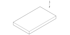
- FIG. 2 is a perspective view of one embodiment of a solder preform.
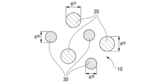
- FIG. 2 is a schematic diagram showing a cross section in the thickness direction of one embodiment of a preform solder.
- 3 is a schematic diagram showing a cross section of a third metal 30A in one embodiment of a solder preform.
- FIG. 4 is a schematic diagram showing a cross section of a third metal 30B in one embodiment of a solder preform.
- FIG. 1 is a SEM image showing a cross section in the thickness direction of the preform solder of Example 1 and Comparative Example 1.
- first metal may mean “particles formed of the first metal,””particles formed of the second metal,””particles formed of the third metal,””particles formed of the fourth metal,” and “particles formed of the fifth metal,” respectively.
- first metal powder may mean "a group of particles formed of a first metal,””a group of particles formed of a second metal,””a group of particles formed of a third metal,””a group of particles formed of a fourth metal,” and “a group of particles formed of a fifth metal,” respectively.
- solder solder 1 shows one embodiment of a solder preform according to the present invention.
- the solder preform 1 is square-shaped and contains a first metal containing Sn, a second metal made of an alloy containing Ni and Fe, and a third metal whose entire surface is made of a metal containing Ni.
- the solder preform 1 is characterized by further containing a third metal whose entire surface is made of a metal containing Ni.
- the first metal includes Sn. Since Sn has excellent ductility, the first metal containing Sn can eliminate voids between the first metals by plastic deformation. In addition, the first metal containing Sn can ensure general performance such as wettability as a soldering material.
- the first metal may include a metal other than Sn.
- metals other than Sn that may be included in the first metal include Ag, Cu, In, Bi, Ni, Ge, P, Co, Ga, Zn, Sb, Pb, Au, Al, Pt, Pd, Fe, Mn, and Zr. These metals other than Sn may include one type or may include two or more types.
- the group of metals other than Sn can be arbitrarily selected from these metals.
- the metal that the first metal may contain may be an elemental metal such as Sn or a metal other than Sn, or may be an alloy of two or more elements of Sn or a metal other than Sn.
- the first metal may be, for example, simple Sn, a mixture of Sn and a metal other than Sn, an alloy of Sn and a metal other than Sn, or a mixture of an alloy containing Sn and a metal other than Sn.
- the first metal may contain unavoidable impurities in addition to the above-mentioned metals. Even if the first metal contains unavoidable impurities, the effects of the present invention are not adversely affected.
- the first metal may be one type or two or more types.
- the melting point of the first metal is preferably 300°C or lower, may be 250°C or lower, or may be 116 to 200°C.
- the melting point of the first metal is equal to or lower than the upper limit of the above-mentioned preferred range, the wettability of the solder can be easily ensured.
- the melting point of the metal to be measured refers to the melting point measured by differential scanning calorimetry (DSC).
- DSC differential scanning calorimetry
- the melting point of the metal to be measured means the temperature at which the amount of heat absorbed per unit time is the highest based on the results of DSC measurement of the metal to be measured.
- the melting point of the metal to be measured means the temperature at the top of that peak.
- the melting point of the metal to be measured means the temperature at the peak top at which the amount of heat absorbed per unit time is the highest among the multiple peak tops.
- the melting point of the metal to be measured is the temperature of the peak top that has the highest amount of heat absorption per unit time among multiple peak tops that the metal to be measured may have.
- the melting points of the first metal and the fourth metal can be measured, for example, using a DSC7020 manufactured by Hitachi High-Tech Science Corp.
- the melting points of the second metal and the third metal can be measured, for example, using a DSC404-F3 Pegasus manufactured by NETZSCH.
- the Sn content in the first metal is preferably 20% by mass or more and 100% by mass or less, based on the total mass of the first metal.
- the Sn content in the first metal is preferably 90% by mass or more, more preferably 95% by mass or more, and even more preferably 100% by mass, based on the total mass of the first metal.
- the second metal is made of an alloy containing Ni and Fe.
- the alloy in the second metal preferably contains Ni and Fe, has a higher melting point than the first metal, and is dispersed within the solder preform.
- the melting point of the alloy in the second metal is preferably more than 300°C, more preferably 500°C or higher, and even more preferably 600 to 1600°C.
- the alloy in the second metal may contain a metal other than Ni and Fe. That is, the second metal may be an alloy of Ni and Fe, or an alloy of Ni, Fe, and a metal other than these, and among these, an alloy of Ni and Fe is preferable.
- metals other than Ni and Fe that the second metal may contain include Sn, Ag, Cu, In, Bi, Ge, P, Co, Ga, Zn, Sb, Pb, Au, Al, Pt, Pd, Mn, and Zr. These metals other than Ni and Fe may contain one type, or may contain two or more types. The group of metals other than Ni and Fe may be arbitrarily selected from these metals.
- the second metal may contain unavoidable impurities in addition to the above-mentioned metals. Even if the second metal contains unavoidable impurities, the effects of the present invention are not adversely affected.
- the second metal may be one type or two or more types.
- the Ni content in the second metal is preferably 80 mass % or more and 99 mass % or less, and more preferably 85 mass % or more and 95 mass % or less, based on the total mass of the second metal.
- the Fe content in the second metal is preferably 1 mass % or more and 20 mass % or less, and more preferably 5 mass % or more and 15 mass % or less, based on the total mass of the second metal.
- particle size of a metal or particle size of a metal powder refers to the average particle size measured on a volume basis using a laser diffraction/scattering type particle size distribution measuring device.
- the average particle size can be measured, for example, using a laser diffraction/scattering particle size distribution measuring device (MT3300EXII) manufactured by Microtrac Bell.
- the second metal preferably has a particle size of 0.1 to 1000 ⁇ m, more preferably 1 to 100 ⁇ m, and even more preferably 5 to 50 ⁇ m.
- the particle size of the second metal is equal to or larger than the lower limit of the above-mentioned preferred range, wettability is easily ensured, whereas when the particle size is equal to or smaller than the upper limit of the above-mentioned preferred range, an intermetallic compound is more easily formed.
- the entire surface of the third metal is made of a metal containing Ni, that is, Ni is exposed on the surface of the third metal.
- the Ni content in the metal forming the entire surface of the third metal is 50 mass % or more and 100 mass % or less with respect to the total mass of the metal forming the entire surface of the third metal.
- the melting point of the metal that forms the entire surface of the third metal is greater than 300°C, preferably 500°C or higher, and more preferably 600 to 1600°C.
- the third metal is preferably dispersed within the solder preform.
- the metal forming the entire surface of the third metal may consist of only Ni, or may contain metals other than Ni.
- Examples of the metal that forms the entire surface of the third metal include simple Ni, an alloy of Ni and a metal other than Ni, and a mixture of an alloy containing Ni and another metal, with simple Ni being preferred.
- examples of the metal other than Ni include Ag, Cu, In, Bi, Ge, P, Co, Ga, Zn, Sb, Pb, Au, Al, Pt, Pd, Fe, Mn, Zr, and Sn. These metals other than Ni may include one type or two or more types. The group of metals other than Ni can be arbitrarily selected from these metals.
- the metal forming the entire surface of the third metal may contain unavoidable impurities in addition to the above-mentioned metals. Even if unavoidable impurities are contained, the effect of the present invention is not affected.
- the metal that forms the entire surface of the third metal may be one type, or two or more types.
- the Ni content in the metal forming the entire surface of the third metal is 50 mass% or more, preferably 70 mass% or more, more preferably 90 mass% or more, even more preferably 95 mass% or more, and particularly preferably 98 mass% or more, relative to the total mass of the metal forming the entire surface.
- the metal forming the entire surface of the third metal contains Fe, it is preferable that the Fe content in the metal forming the entire surface of the third metal is greater than or equal to 0 mass% and less than 5 mass% relative to the total mass of the metal forming the entire surface of the third metal.
- the third metal preferably has a particle size of 0.1 to 1000 ⁇ m, more preferably 1 to 300 ⁇ m, and even more preferably 10 to 200 ⁇ m.
- the particle size of the third metal is at least the lower limit of the above-mentioned preferred range, the thermal conductivity of the solder joint is easily increased.
- the third metal may have a uniform composition throughout, or as described in (2) below, the third metal may have a structure having a plurality of different compositions.
- the third metal may be a metal consisting only of Ni, as described in (1-1) below, or may be a metal containing Ni and a metal other than Ni, as described in (1-2) below.
- the third metal may have a core portion and a surface layer, as described in (2) below.
- the third metal has a uniform composition as a whole (1-1)
- the third metal is composed only of Ni
- the composition of the third metal is different from the compositions of the first metal and the second metal.
- the content of Ni in the metal forming the entire surface of the third metal is 100 mass% relative to the total mass of the metal forming the entire surface of the third metal
- the proportion of Ni in the surface of the third metal is 100% relative to the entire area (100%) of the surface of the third metal.
- the third metal may contain unavoidable impurities in addition to Ni. Even if the third metal contains unavoidable impurities, the effects of the present invention are not adversely affected.
- the composition of the third metal is different from the compositions of the first metal and the second metal.
- the third metal may be a mixture of Ni and a metal other than Ni, an alloy of Ni and a metal other than Ni, or a mixture of an alloy containing Ni and a metal other than Ni.
- metals other than Ni that the third metal may contain include Ag, Cu, In, Bi, Ge, P, Co, Ga, Zn, Sb, Pb, Au, Al, Pt, Pd, Fe, Mn, Zr, and Sn. These metals other than Ni may contain one type or two or more types. The group of metals other than Ni may be arbitrarily selected from these metals.
- the third metal may contain unavoidable impurities in addition to the above-mentioned metals. Even if the third metal contains unavoidable impurities, the effects of the present invention are not adversely affected.
- the third metal of (1-2) may be one type or two or more types.
- the content of Ni in the third metal is 50 mass% or more and 100 mass% or less, preferably 70 mass% or more, more preferably 90 mass% or more, even more preferably 95 mass% or more, and particularly preferably 98 mass% or more, relative to the total mass of the third metal.
- the content of Fe in the third metal is preferably 0 mass % or more and less than 5 mass % with respect to the total mass of the third metal.
- the melting point of the third metal is greater than 300°C, preferably greater than 500°C, and more preferably 600 to 1600°C.
- the particle size of the third metal is preferably 0.1 to 1000 ⁇ m, more preferably 1 to 300 ⁇ m, and even more preferably 10 to 200 ⁇ m.
- the third metal 30A has a core portion 301 and a surface layer 302 covering the core portion 301.
- Rc means the diameter of the core portion 301.
- Rs means the thickness of the surface layer 302.
- the "surface layer covering the core portion” can also be rephrased as a "covering layer covering the core portion”.
- the composition of the metal forming the surface layer 302 is different from the composition of the metal forming the core portion 301.
- the composition of the third metal is different from the compositions of the first metal and the second metal.
- the composition of the metal forming the surface layer of the third metal is different from the compositions of the first metal and the second metal.
- the metal forming the surface layer of the third metal may be made of only Ni, or may be a metal containing Ni and a metal other than Ni. That is, the metal forming the surface layer of the third metal may be Ni alone, or may be an alloy of Ni and a metal other than Ni.
- the metal forming the surface layer of the third metal is preferably Ni alone.
- Metals other than Ni that may be included in the metal forming the surface layer of the third metal include, for example, Ag, Cu, In, Bi, Ge, P, Co, Ga, Zn, Sb, Pb, Au, Al, Pt, Pd, Fe, Mn, Zr, and Sn. These metals other than Ni may include one type or two or more types. The group of metals other than Ni may be arbitrarily selected from these metals.
- the metal forming the surface layer of the third metal may contain unavoidable impurities in addition to the above-mentioned metals. Even if unavoidable impurities are contained, the effect of the present invention is not affected.
- the surface layer of the third metal may be formed of one type of metal or two or more types of metal.
- the content of Ni in the metal forming the surface layer of the third metal is 50 mass% or more and less than 100 mass%, preferably 70 mass% or more, more preferably 80 mass% or more, even more preferably 90 mass% or more, particularly preferably 95 mass% or more, and most preferably 98 mass% or more, relative to the total mass of the metal forming the surface layer of the third metal.
- the metal forming the surface layer of the third metal contains Fe, it is preferable that the Fe content in the metal forming the surface layer of the third metal is greater than or equal to 0 mass% and less than 5 mass% relative to the total mass of the metal forming the surface layer of the third metal.
- the ratio of the surface area of the core portion covered by the surface layer to the total surface area (100%) of the core portion is preferably 50% or more and 100% or less, more preferably 70% or more and 100% or less, even more preferably 90% or more and 100% or less, particularly preferably 95% or more and 100% or less, and most preferably 100%.
- the thickness Rs of the surface layer of the third metal may be, for example, 0.01 ⁇ m or more and 100 ⁇ m or less.
- the thickness of the surface layer of the third metal may be 0.1 ⁇ m or more, 0.3 ⁇ m or more, 0.5 ⁇ m or more, 0.75 ⁇ m or more, 1 ⁇ m or more, or 2 ⁇ m or more.
- the average thickness of the surface layer of the third metal may be 50 ⁇ m or less, 30 ⁇ m or less, 10 ⁇ m or less, 5 ⁇ m or less, 3 ⁇ m or less, or 2 ⁇ m or less.
- the thickness Rs of the surface layer of the third metal, the diameter Rc of the core portion of the third metal described later, the thickness Ri of the intermediate layer, and the thickness of the layer of the fourth metal containing Sn can be measured from the cross-sectional structure of the layer of the third metal and the layer of the fourth metal containing Sn using an optical microscope, a SEM, a transmission electron microscope (TEM), or the like.
- the thickness Rs of the surface layer and the thickness Ri of the intermediate layer can be calculated as the average value of the thicknesses measured at three or more cross sections.
- the diameter Rc of the core portion can be calculated by measuring the diameters of three or more third metal particles and averaging these values.
- the diameter Rc of the core portion of the third metal can be measured as follows.
- the particle size of the metal powder prepared for use as the core portion can be taken as the diameter Rc.
- the surface layer of the third metal may be a plated layer formed by a plating process.
- Examples of the plating method include known electroplating and electroless plating.
- the melting point of the metal forming the surface layer of the third metal is greater than 300°C, preferably greater than 500°C, and more preferably 600 to 1600°C.
- the metal forming the core portion of the third metal may be one type of elemental metal, a mixture of two or more types of elemental metals, an alloy formed of two or more types of metal elements, a mixture of alloys formed of two or more types of metal elements, or a mixture of an alloy formed of two or more types of metal elements and an elemental metal.
- Examples of metals that may be included in the core portion of the third metal include Ag, Cu, In, Bi, Ni, Ge, P, Co, Ga, Zn, Sb, Pb, Au, Al, Pt, Pd, Fe, Mn, Zr, and Sn. These metals may be included in one type or in two or more types.
- the group of metals that may be included in the core portion can be arbitrarily selected from these metals.
- the core portion of the third metal may contain unavoidable impurities in addition to the above-mentioned metals. Even if the core portion of the third metal contains unavoidable impurities, the effect of the present invention is not affected.
- the metal forming the core portion of the third metal may be one type or two or more types.
- the diameter Rc of the core portion of the third metal is preferably 0.1 to 1000 ⁇ m, more preferably 3 to 300 ⁇ m, further preferably 5 to 200 ⁇ m, particularly preferably 20 to 200 ⁇ m, and most preferably 70 to 200 ⁇ m.
- the diameter Rc may be 150 ⁇ m or less, 100 ⁇ m or less, 75 ⁇ m or less, 50 ⁇ m or less, 30 ⁇ m or less, 20 ⁇ m or less, or 15 ⁇ m or less,
- the ratio of Rc to Rs may be 0.1 to 1000, 1 to 300, or 5 to 200.
- the third metal 30A in (2) may be one type or two or more types.
- the third metal 30B may have an intermediate layer 303 between the core portion 301 and the surface layer 302 covering the core portion 301.
- the surface layer 302 covers the core portion 301 via the intermediate layer 303.
- the intermediate layer 303 is adjacent to the core portion 301 and is also adjacent to the surface layer 302. Ri means the thickness of the intermediate layer 303.
- the intermediate layer 303 may cover a part of the core portion 301 or may cover the entire core portion 301, and it is preferable that the intermediate layer 303 covers the entire core portion 301.
- the third metal 30B is similar to the third metal 30A except that it has the intermediate layer 303. By the third metal 30B having the intermediate layer 303, it becomes easier to provide the surface layer 302 of the third metal 30B.
- the composition of the metal forming the intermediate layer 303 is different from the metal forming the core portion 301 and the metal forming the surface layer 302 .
- the intermediate layer may be one layer or two or more layers.
- the metal forming the intermediate layer may be a single type of metal, or an alloy formed from two or more types of metal elements.
- Metals that the intermediate layer may contain include, for example, Ag, Cu, In, Bi, Ni, Ge, P, Co, Ga, Zn, Sb, Pb, Au, Al, Pt, Pd, Fe, Mn, Zr, and Sn. These metals may be contained alone or in combination of two or more. The group of metals that the intermediate layer may contain can be arbitrarily selected from these metals.
- the intermediate layer may contain unavoidable impurities in addition to the above-mentioned metals. Even if the intermediate layer contains unavoidable impurities, the effects of the present invention are not adversely affected.
- the intermediate layer may be formed of one type of metal or two or more types of metal.
- the thickness Ri of the intermediate layer may be, for example, 0.01 ⁇ m or more and 100 ⁇ m or less, 1 ⁇ m or more and 50 ⁇ m or less, or 2 ⁇ m or more and 10 ⁇ m or less.
- the intermediate layer may be a plating formed by a plating process.
- Examples of the plating method include known electroplating and electroless plating.
- Examples of metals forming the core portion 301 and the surface layer 302 of the third metal 30B include the same metals as those described above for the third metal 30A.
- the third metal 30B may be one type or two or more types.
- the preform solder according to the present embodiment may further contain a fourth metal containing Sn that coats the third metal.
- the fourth metal may coat a part of the third metal, or may coat the entire third metal, and preferably coats the entire third metal.
- the third metal may be covered with a layer formed of a fourth metal. In this case, the layer of the fourth metal covering the third metal may be a single layer or two or more layers.
- the fourth metal may contain a metal other than Sn. That is, the fourth metal may be simple Sn, a mixture of Sn and a metal other than Sn, an alloy of Sn and a metal other than Sn, or a mixture of an alloy containing Sn and a metal other than Sn.
- the fourth metal is preferably simple Sn.
- Examples of metals other than Sn that the fourth metal may contain include Ag, Cu, In, Bi, Ni, Ge, P, Co, Ga, Zn, Sb, Pb, Au, Al, Pt, Pd, Fe, Mn, and Zr.
- the fourth metal may contain one type of metal other than Sn, or may contain two or more types.
- the group of metals other than Sn can be arbitrarily selected from these metals.
- the fourth metal may contain unavoidable impurities in addition to the above-mentioned metals. Even if the fourth metal contains unavoidable impurities, the effect of the present invention is not affected.
- the fourth metal may be formed of one type of metal or two or more types of metal.
- the content of Sn in the fourth metal is preferably 20 mass% or more and 100 mass% or less, more preferably 90 mass% or more, even more preferably 95 mass% or more, and particularly preferably 100 mass%, based on the total mass of the fourth metal.
- the average thickness of the fourth metal layer may be, for example, 0.01 ⁇ m or more and 100 ⁇ m or less, 1 ⁇ m or more and 50 ⁇ m or less, or 2 ⁇ m or more and 10 ⁇ m or less.
- the fourth metal layer may be a plated layer formed by a plating process.
- Examples of the plating method include known electroplating and electroless plating.
- the melting point of the fourth metal is preferably 300°C or lower, may be 250°C or lower, or may be 116 to 200°C.
- the melting point of the fourth metal is equal to or lower than the upper limit of the above-mentioned preferred range, the wettability of the preform solder is improved when it is melted, and further, a reduction in voids can be expected.
- the fourth metal contains Sn, which improves wettability when the preform solder melts, and is also expected to reduce voids.
- the metal layer melts after heating begins to melt the preform solder, exposing the surface layer of the third metal, so it does not impede the effect of the present application.
- the mixing ratio of the first metal, the second metal, and the third metal is such that the content of the first metal is preferably 20 to 95 mass %, more preferably 20 to 90 mass %, even more preferably 40 to 90 mass %, particularly preferably 50 to 85 mass %, and most preferably 60 to 75 mass %, relative to the total content of the first metal, the second metal, and the third metal.
- the mixing ratio of the first metal, the second metal, and the third metal is preferably such that the content of the second metal is 1 to 70 mass %, more preferably 3 to 50 mass %, even more preferably 5 to 40 mass %, particularly preferably 5 to 30 mass %, and most preferably 5 to 25 mass %, relative to the total content of the first metal, the second metal, and the third metal.
- the content of the second metal is equal to or greater than the lower limit of the preferred range, the generation of voids during Sn melting is easily suppressed. Also, the heat resistance of the solder joint is further improved.
- the content of the second metal is equal to or less than the upper limit of the preferred range, the generation of a porous structure due to the formation of intermetallic compounds is suppressed, thereby suppressing the generation of voids and making it easier to maintain shear strength. In particular, the generation of microvoids inside the solder joint is easily suppressed.
- the mixing ratio of the first metal, the second metal, and the third metal is such that the content of the third metal is preferably 1 to 70 mass %, more preferably 3 to 50 mass %, even more preferably 5 to 40 mass %, particularly preferably 5 to 30 mass %, and most preferably 20 to 30 mass %, relative to the total content of the first metal, the second metal, and the third metal.
- the content of the third metal is equal to or more than the lower limit of the above-mentioned preferred range, the thermal conductivity of the solder joint is easily increased, and when the content is equal to or less than the upper limit of the above-mentioned preferred range, the generation of voids is suppressed.
- the total content of the first metal, the second metal, and the third metal does not exceed 100% by mass.
- the mixture ratio of the content of the fourth metal to the content of the third metal expressed as a mass ratio of the fourth metal/third metal, may be 0.01 to 10.
- the ratio of the content of the first metal to the content of the second metal is preferably 1 to 50, and more preferably 2 to 9.
- the ratio of the content of the second metal to the content of the third metal is preferably 0.1 or more and 10 or less.
- the preform solder according to the first embodiment is not limited to the above-described embodiment, and may contain a metal other than the first metal, the second metal, the third metal, and the fourth metal (hereinafter also referred to as a "fifth metal").
- the fifth metal is not particularly limited in composition as long as it has a composition different from those of the first metal, the second metal, the third metal, and the fourth metal.
- the fifth metal is preferably a powder made of any one of the elemental metals Ni, Ag, Cu, In, Bi, Ge, P, Co, Ga, Zn, Sb, Pb, Au, Al, Pt, Pd, Fe, Mn, Zr, and Sn, or an alloy formed of two or more of these elemental metals.
- the particle size of the fifth metal is preferably 0.1 to 1000 ⁇ m, more preferably 1 to 100 ⁇ m, and even more preferably 5 to 50 ⁇ m.
- the fifth metal may include one type of metal or may include two or more types of metals.
- the fifth metal is not limited to one type, and metal powders of two or more different compositions may be used.
- FIG. 2 is a schematic diagram showing a cross section in the thickness direction of one embodiment of a solder preform.
- 2 has a metal structure including a first phase 10 which is a continuous phase, a second phase 20 which is dispersed in the first phase, and a third phase 30 which is dispersed in the first phase.
- R20 means the diameter of the second phase 20
- R30 means the diameter of the third phase 30.
- the first phase 10 contains Sn. Metal grain boundaries may be present in the first phase 10.
- the second phase 20 is made of an alloy containing Ni and Fe.
- the third phase 30 is made of a metal whose entire surface is formed of a metal containing Ni.
- the first phase 10 is a continuous phase and is composed of a metal containing Sn.
- the description of the metal containing Sn and its content is the same as that of the first metal described above.
- crystal grain boundaries may exist between the metal crystals containing Sn.
- the melting point of the metals constituting the first phase as a whole can be measured in the same manner as the melting point of the first metal.
- the melting point of the metals constituting the first phase as a whole is determined by the temperature of the peak top having the highest heat absorption per unit time among the plurality of peak tops that the plurality of metals constituting the first phase may have.
- the overall melting point of the metals constituting the second phase is similarly defined.
- the overall melting point of the metal forming the entire surface of the third phase is similarly defined.
- the melting point of the metals constituting the third phase as a whole is defined in the same manner.
- the melting point of the metal forming the surface layer of the third phase as a whole is defined in the same manner.
- the overall melting point of the metals constituting the fourth phase is defined in a similar manner.
- the explanation for the melting point of the metals constituting the first phase as a whole is the same as the explanation for the melting point of the first metal.
- the second phase 20 is dispersed in the first phase 10 .
- the second phase 20 is composed of an alloy containing Ni and Fe.
- the description of the alloy containing Ni and Fe, its particle size, its content, etc. are the same as those in the above ⁇ Second metal>.
- the explanation for the melting point of the alloy constituting the second phase as a whole is the same as the explanation for the melting point of the second metal.
- the grain size of a phase can be measured and calculated from a cross-sectional structure containing that phase using an optical microscope, SEM, transmission electron microscope (TEM), etc.
- the grain size of a phase can be calculated by measuring the diameters of three or more phases and averaging them.
- the particle size of the second phase can be the particle size of the second metal powder prepared to form the second phase.
- the third phase 30 is dispersed in the first phase 10 .
- the entire surface of the third phase 30 is made of a metal containing Ni.
- the metal forming the entire surface of the third phase 30 is preferably simple Ni.
- the explanation of the metal whose entire surface is made of Ni, its particle size, its content, etc. are the same as those in the above ⁇ Third metal>.
- the explanation for the melting point of the metal forming the entire surface of the third phase is the same as that for the melting point of the metal forming the entire surface of the third metal.
- the overall composition of the metal that constitutes the third phase is different from the overall composition of the metal that constitutes the first phase and the overall composition of the alloy that constitutes the second phase.
- the explanation regarding the melting point of the metals constituting the third phase as a whole is similar to the explanation regarding the melting point of the third metal.
- the particle size of the third phase may be the particle size of a third metal powder prepared to form the third phase.
- the overall composition of the metal forming the surface layer of the third phase is different from the overall composition of the metal forming the first phase and the overall composition of the alloy forming the second phase.
- the overall melting point of the metal forming the surface layer of the third phase is similar to the melting point of the metal forming the surface layer of the third metal.
- the explanations for the diameter Rc of the core portion and the thickness Rs of the surface layer of the third phase are the same as those for the diameter Rc of the core portion and the thickness Rs of the surface layer of the third metal, respectively.
- the preform solder 1 may have a metal structure further including a fourth phase containing Sn that covers the third phase.
- the content of the metals constituting the phase means “the total content of the metals constituting the phase”.
- the mixing ratio of the metal constituting the first phase 10, the alloy constituting the second phase 20, and the metal constituting the third phase 30 is preferably such that the content of the metal constituting the first phase is 20 to 95 mass %, more preferably 20 to 90 mass %, even more preferably 40 to 90 mass %, particularly preferably 50 to 85 mass %, and most preferably 60 to 75 mass %, relative to the total content of the metal constituting the first phase, the metal constituting the second phase, and the metal constituting the third phase.
- the mixing ratio of the metal constituting the first phase 10, the alloy constituting the second phase 20, and the metal constituting the third phase 30 is, from the viewpoint of achieving both bondability and shear strength, preferably such that the content of the alloy constituting the second phase 20 is 1 to 70 mass % relative to the total content of the metal constituting the first phase 10, the alloy constituting the second phase 20, and the metal constituting the third phase 30, more preferably 3 to 50 mass %, even more preferably 5 to 40 mass %, particularly preferably 5 to 30 mass %, and most preferably 5 to 25 mass %.
- the content of the alloy constituting the second phase 20 is equal to or greater than the lower limit of the above-mentioned preferred range, the generation of voids during Sn melting is easily suppressed. Also, the heat resistance of the solder joint is further improved.
- the content of the alloy constituting the second phase 20 is equal to or less than the upper limit of the above-mentioned preferred range, the generation of a porous structure due to the formation of intermetallic compounds is suppressed, thereby suppressing the generation of voids and making it easier to maintain the shear strength.
- the mixing ratio of the metal constituting the first phase 10, the alloy constituting the second phase 20, and the metal constituting the third phase 30 is preferably such that the content of the alloy constituting the third phase 30 is 1 to 70 mass %, more preferably 3 to 50 mass %, even more preferably 5 to 40 mass %, particularly preferably 5 to 30 mass %, and most preferably 20 to 30 mass %, relative to the total content of the metal constituting the first phase 10, the alloy constituting the second phase 20, and the metal constituting the third phase 30.
- the content of the metal constituting the third phase 30 is equal to or more than the lower limit of the above-mentioned preferred range, the thermal conductivity of the solder joint is easily increased, and when the content is equal to or less than the upper limit of the above-mentioned preferred range, the occurrence of voids is suppressed.
- the total content of the metal constituting the first phase 10, the content of the metal constituting the second phase 20, and the content of the metal constituting the third phase 30 does not exceed 100% by mass.
- the mixture ratio of the content of the metal constituting the fourth phase to the content of the metal constituting the third phase may be 0.01 to 10 as a mass ratio represented by the fourth phase/third phase.
- the ratio of the content of the metal constituting the first phase 10 to the content of the metal constituting the second phase 20, expressed as the content of the metal constituting the first phase 10/the content of the metal constituting the second phase 20, is preferably 1 to 50, more preferably 2 to 9.
- the ratio of the content of the metal constituting the second phase 30 to the content of the metal constituting the third phase 30, expressed as the content of the metal constituting the second phase 20/the content of the metal constituting the third phase 30, is preferably 0.1 or more and 10 or less.
- the preform solder according to the second embodiment is not limited to the above-mentioned embodiment, and may further have a fifth phase dispersed in the first phase in addition to the first, second, third and fourth phases.
- the explanation of the fifth phase is the same as that of the ⁇ fifth metal> described above.
- the metal structure constituting the preform solder 1 comprises a first phase 10, a second phase 20, and a third phase 30, while being characterized in that a phase containing an intermetallic compound is not present between the first phase 10 and the second phase 20, or the presence ratio of such a phase is low.
- Preform solder 1 has a small content of intermetallic compounds of Sn and Ni in the metal structure, and the content is preferably 0 mass% or more and 70 mass% or less, more preferably 0 mass% or more and 30 mass% or less, and most preferably 0 mass%, relative to the total mass of the metal structure.
- the content of the intermetallic compound of Sn and Ni in the metal structure is equal to or less than the upper limit of the preferred range, the generation of voids during solder joining is more easily suppressed.
- Examples of the shape of the preform solder according to the first or second embodiment described above include a square shape, ribbon shape, disk shape, washer shape, chip shape, wire shape, etc.
- the thermal conductivity of the preform solder according to the first or second embodiment described above is preferably 27 to 100 W/(m ⁇ K), more preferably 30 to 70 W/(m ⁇ K), and even more preferably 45 to 70 W/(m ⁇ K).
- the thermal conductivity of the solder preform can be measured, for example, as follows.
- the prepared preform solder is cut to a size of 45 mm x 15 mm to obtain a test piece.
- the test piece is then sandwiched between ceramic plates and pressurized and heated.
- the pressurized and heated profile is heating at a heating rate of 0.25°C/sec, followed by holding at 250°C for 120 seconds, followed by cooling at a cooling rate of 2°C/sec.
- the pressure is 0.5 MPa.
- the atmosphere during heating is N2 (95%) + H2 (5%).
- the electrical resistivity is measured by the four-probe method using a measuring device such as Loresta-GP MCP-T610 (manufactured by MITSUBISHI CHEMICAL ANALYTECH).
- Two test pieces of the preform solder are prepared, and the probes are placed on three points near the center of each test piece, away from the ends, to measure the electrical resistivity. The average value of these six measured values is taken
- the preform solder according to the first or second embodiment described above can be manufactured using known manufacturing methods, such as melting and rolling. Among these, it is preferable to use the rolling method for manufacturing the preform solder according to this embodiment, since this method is particularly effective in suppressing the generation of intermetallic compounds between Sn and Ni, suppresses the generation of large voids, and reduces the amount of voids that are generated.
- the preform solder according to the present embodiment described above contains a first metal containing Sn, a second metal consisting of an alloy containing Ni and Fe, and a third metal whose entire surface is formed of a metal containing Ni.
- the preform solder according to this embodiment contains a second metal, which suppresses the generation of porous structures due to the formation of intermetallic compounds, and suppresses the generation of voids, particularly during solder joining under high temperature conditions (250°C or higher), making it easier to maintain shear strength.
- the solder preform according to the present embodiment contains a third metal, which makes it possible to increase the thermal conductivity of the solder joint.
- the reason why such an effect is obtained is not clear, but is presumed to be as follows.
- the intermetallic compounds of Cu and Sn and the intermetallic compounds of Ni and Sn have low thermal conductivity compared to Cu, Ni, etc.
- the thermal conductivities of Cu and Ni are 401 W/m ⁇ K and 88.5 W/m ⁇ K, respectively
- the thermal conductivities of the intermetallic compounds Cu 6 Sn 5 (Cu 3 Sn) and Ni 3 Sn 4 are 34 W/m ⁇ K and 20 W/m ⁇ K, respectively.
- the entire surface of the third metal is made of a metal containing Ni, and Ni has low reactivity with Sn, so Ni3Sn4 is unlikely to be generated. In other words, the surface of the third metal is unlikely to react with Sn in the preform solder to form an intermetallic compound, so it is possible to increase the thermal conductivity of the solder joint. Even if the third metal is covered with a metal layer containing Sn, the effect of suppressing the formation of intermetallic compounds by Ni according to the present application can be exerted as long as the metal layer containing Sn melts immediately when the preform solder is joined.
- One embodiment of a method for manufacturing a preform solder according to the present invention is a manufacturing method including a mixing step of mixing a first metal powder containing Sn, a second metal powder made of an alloy containing Ni and Fe, and a third metal powder whose entire surface is formed of a metal containing Ni, to prepare a metal powder mixture, and a rolling step of rolling the metal powder mixture to produce a preform solder.
- the metal constituting the first metal powder used in this embodiment is a metal containing Sn.
- the description of the metal containing Sn is the same as that of the first metal described above.
- the melting point of the first metal powder is preferably 300°C or lower, may be 250°C or lower, or may be 116 to 200°C. When the melting point of the first metal powder is equal to or lower than the upper limit of the above-mentioned preferred range, the wettability of the solder can be easily ensured.
- the Sn content in the first metal powder is preferably 20% by mass or more and 100% by mass or less, based on the total mass of the first metal powder.
- the Sn content in the first metal powder is preferably 90% by mass or more, more preferably 95% by mass or more, and even more preferably 100% by mass, based on the total mass of the first metal powder.
- the first metal powder preferably has a particle size of 0.1 to 1000 ⁇ m, and more preferably 1 to 100 ⁇ m.
- the particle size of the first metal powder is at least the lower limit of the above-mentioned preferred range, wettability is easily ensured, and when the particle size is at most the upper limit of the above-mentioned preferred range, an intermetallic compound is more easily formed.
- the metal constituting the second metal powder used in this embodiment is an alloy containing Ni and Fe, and has a higher melting point than the first metal powder.
- the explanation of the alloy containing Ni and Fe is the same as that of the second metal powder described above.
- the melting point of the alloy in the second metal powder is preferably above 300°C, more preferably 500°C or higher, and even more preferably 600 to 1600°C. When the melting point of the second metal powder is above the lower limit of the above-mentioned preferred range, the shear strength of the solder joint is easily increased even in a high-temperature operating environment.
- the Ni content in the second metal powder is preferably 80 mass % or more and 99 mass % or less, and more preferably 85 mass % or more and 95 mass % or less, based on the total mass of the second metal powder.
- the Fe content in the second metal powder is preferably 1 mass % or more and 20 mass % or less, and more preferably 5 mass % or more and 15 mass % or less, relative to the total mass of the second metal powder.
- the second metal powder preferably has a particle size of 0.1 to 1000 ⁇ m, more preferably 1 to 100 ⁇ m, and even more preferably 5 to 50 ⁇ m.
- the particle size of the second metal powder is at least the lower limit of the above-mentioned preferred range, wettability is easily ensured, and when it is at most the upper limit of the above-mentioned preferred range, intermetallic compounds are more easily formed.
- Third metal powder The entire surface of the third metal powder used in this embodiment is formed of a metal containing Ni.
- the metal constituting the third metal powder is the same as the above-mentioned ⁇ third metal>.
- the entire surface of the third metal powder is preferably composed of pure Ni.
- the third metal preferably has a particle size of 0.1 to 1000 ⁇ m, more preferably 1 to 300 ⁇ m, and even more preferably 10 to 200 ⁇ m.
- the particle size of the third metal is at least the lower limit of the above-mentioned preferred range, the thermal conductivity of the solder joint is easily increased.
- the first metal powder, the second metal powder, and the third metal powder are mixed together to prepare a metal powder mixture.
- the compounding ratio when mixing the two is preferably 20 to 95 parts by mass of the first metal powder, 1 to 70 parts by mass of the second metal powder, and 1 to 70 parts by mass of the third metal powder, and more preferably 20 to 90 parts by mass of the first metal powder, 3 to 50 parts by mass of the second metal powder, and 3 to 50 parts by mass of the third metal powder. It is more preferable to mix the first metal powder at a ratio of 40 to 90 parts by mass, 5 to 40 parts by mass of the second metal powder, and 5 to 40 parts by mass of the third metal powder.
- the first metal powder it is particularly preferable to mix the first metal powder at a ratio of 50 to 85 parts by mass, 5 to 30 parts by mass of the second metal powder, and 5 to 30 parts by mass of the third metal powder. It is particularly preferable to mix the first metal powder at a ratio of 60 to 75 parts by mass, 5 to 25 parts by mass of the second metal powder, and 20 to 30 parts by mass of the third metal powder.
- the mixing step may further include a step of coating the third metal powder with a fourth metal.
- the coating step may be, for example, a step of plating the third metal powder with the fourth metal.
- the mixing step may include a step of premixing the third metal powder with the fourth metal containing Sn prior to the coating step.
- the explanation of the fourth metal is the same as that of the ⁇ fourth metal> described above in the first embodiment of the preform solder.
- the mass ratio of the fourth metal to the third metal powder expressed as a mass ratio of fourth metal/third metal powder, may be 0.01 to 10.
- the compounding ratio of the first metal powder to the second metal powder expressed as the mass of the first metal powder/the mass of the second metal powder, is preferably 1 to 50, more preferably 2 to 9.
- the compounding ratio of the second metal powder to the third metal powder expressed as the mass of the second metal powder/the mass of the third metal powder, is preferably 0.1 or more and 10 or less.
- the metal powder mixture prepared in the mixing step is rolled and formed into a desired shape to produce a solder preform.
- the metal powder mixture can be rolled by a known rolling method, for example, by using a twin-roll rolling machine, etc.
- the number of times of rolling and the rolling load applied to the metal powder mixture can be appropriately set according to the desired shape and thickness of the target preform solder.
- the method for manufacturing a solder preform according to this embodiment includes a mixing step of mixing the first metal powder, the second metal powder, and the third metal powder to prepare a metal powder mixture, and a rolling step.
- the mixing step the third metal powder, the entire surface of which is made of a metal containing Ni, is used, so that it is possible to increase the thermal conductivity of the solder joint.
- an alloy containing Ni and Fe is used as the second metal powder and the metal powder mixture is rolled and processed, the generation of intermetallic compounds between Sn and Ni in the metal structure is suppressed, and a preform solder in which the generation of voids during solder joining is further suppressed can be easily produced.
- the method for producing a solder preform according to this embodiment is useful as a method for producing the solder preform according to the first or second embodiment described above.
- the method for manufacturing preform solder according to the present invention is not limited to the above-described embodiment, and may be an embodiment that further includes other steps in addition to the above-described mixing and rolling steps.
- the method for manufacturing the preform solder according to the present invention is not limited to the above-mentioned embodiment, and a metal powder other than the first metal powder, the second metal powder, and the third metal powder (hereinafter, also referred to as the "fifth metal powder") may be used.
- the metal constituting the fifth metal powder is the same as the above-mentioned "fifth metal”.
- One embodiment of a method for manufacturing a solder joint according to the present invention is a manufacturing method for forming a joint between objects using a preform solder manufactured by the above-mentioned (manufacturing method for preform solder).
- a semiconductor element and a substrate can be bonded.
- the semiconductor element include a silicon carbide (SiC) chip and a Si chip.
- the substrate include a circuit board, a ceramic substrate, a metal substrate, a DCB (Direct Copper Bonding) substrate, etc.
- the electrode on the substrate may be, for example, a Cu electrode, or a Cu electrode that has been plated with Sn, Ni, Ni-Au, Ni-Pd, or Ni-Pd-Au.
- flux may be applied in advance to one or both surfaces of the preform solder that will become the bonding surfaces, the bonding surface of the semiconductor element, or the bonding surface of the substrate.
- the temperature at which the semiconductor element and the substrate are joined is preferably, for example, 120°C or higher and 400°C or lower, but may also be 200°C or higher and 400°C or lower, or 250°C or higher and 400°C or lower, and the method for manufacturing the solder joint of this embodiment is useful for joining under high temperature conditions (250°C or higher).
- the atmosphere in which the objects are joined may be an air atmosphere, an inert atmosphere such as a nitrogen atmosphere, or a reducing atmosphere.
- a nitrogen atmosphere the pressure applied during bonding is preferably adjusted to 0.1 MPa or more and 10 MPa or less.
- the formation of an intermetallic compound by the third metal in the solder joint after reflow is suppressed, thereby making it possible to improve thermal conductivity.
- the alloy containing Ni and Fe reacts with the first metal containing Sn to generate an intermetallic compound, which further improves the heat resistance of the solder joint.
- the generation of voids in the solder joint is further suppressed, making it possible to manufacture a solder joint with increased shear strength.
- the method for manufacturing a solder joint according to this embodiment is particularly useful in applications that require high-temperature solder that does not melt during operation under high-temperature conditions, such as in power semiconductor devices.
- the particle size of the metal powder was measured by measuring the average particle size on a volume basis using a laser diffraction/scattering type particle size distribution measuring device (MT3300EXII) manufactured by Microtrac Bell.
- the melting points of the metal powders were determined by differential scanning calorimetry (DSC).
- the melting points of the first metal powder were measured using a DSC7020 manufactured by Hitachi High-Tech Science Corporation, and the melting points of the second metal powder and the third metal powder were measured using a DSC404-F3 Pegasus manufactured by NETZSCH.
- First metal powder Metal powder of 100% Sn by mass (100% Sn by mass powder) Average particle size 65 ⁇ m (maximum particle size 75 ⁇ m), melting point 232°C
- Second metal powder Metal powder consisting of an alloy of 90% Ni by mass and 10% Fe by mass (Ni-10% Fe by mass powder), average particle size 12.8 ⁇ m
- Third metal powder Third metal powder (1) Metal powder containing 100% Ni by mass (100% Ni by mass powder) Average particle size: 50.7 ⁇ m
- Third metal powder (2) Ni-plated Cu 100% by mass core balls As the core portions of the third metal powder (2), Cu 100% by mass core balls were used.
- the average particle size of the core portions i.e., the diameter Rc of the core portions
- the surface layer of the third metal powder (2) was plated with 100 mass % Ni.
- the plating thickness i.e., the thickness Rs of the surface layer was 1 to 3 ⁇ m.
- Third metal powder (3) Ni-plated Cu 100% by mass core balls As the core portions of the third metal powder (3), Cu 100% by mass core balls were used. The average particle size of the core portions (i.e., the diameter Rc of the core portions) was 55.3 ⁇ m. The surface layer of the third metal powder (3) was plated with 100 mass % Ni. The plating thickness (i.e., the thickness Rs of the surface layer) was 1 to 3 ⁇ m.
- the average particle size of the cores i.e., the diameter Rc of the cores
- the surface layer of the third metal powder (4) was plated with 100 mass % Ni.
- the plating thickness i.e., the thickness Rs of the surface layer was 1 to 3 ⁇ m.
- the plated core balls of the third metal powders (2) to (4) were Cu 100% core balls whose entire surface was coated with Ni 100% by mass plating.
- the Ni 100% by mass plating was formed by electroplating in all cases.
- the melting point of the Ni 100% by mass plating was 1455°C.
- the first metal powder, the second metal powder, the third metal powder, and the fifth metal powder were each prepared as described above. Using these metal powders, the solder preforms of the respective examples were manufactured.
- Example 1 Mixing process: A metal powder mixture was prepared by stirring 75 parts by mass of 100% Sn powder having an average particle size of 65 ⁇ m as the first metal powder, 20 parts by mass of Ni-10% by mass Fe powder having an average particle size of 12.8 ⁇ m as the second metal powder, and 5 parts by mass of the third metal powder (2) as the third metal powder.
- Rolling process Next, the prepared metal powder mixture was introduced into the hopper of a twin-roll rolling mill, the surface temperature of the rolling rolls was set to 100° C., and the rolling load was set to about 25 kN to obtain a strip-shaped rolled material. Thereafter, rolling was repeated to obtain a strip-shaped preform solder having a thickness of 100 ⁇ m.
- Example 2 A strip-shaped preform solder having a thickness of 100 ⁇ m was obtained by sequentially carrying out the mixing step and the rolling step in the same manner as in Example 1, except that the third metal powder was used as the third metal powder and the first metal powder, the second metal powder and the third metal powder (1) were used in a predetermined mixing ratio as shown in Table 1.
- Example 5 A strip-shaped preform solder having a thickness of 100 ⁇ m was obtained by sequentially carrying out the mixing step and the rolling step in the same manner as in Example 1, except that the third metal powder (3) was used as the third metal powder and the first metal powder, the second metal powder and the third metal powder (3) were used in a predetermined mixing ratio as shown in Table 1.
- Example 7 A strip-shaped preform solder having a thickness of 100 ⁇ m was obtained by sequentially carrying out the mixing step and the rolling step in the same manner as in Example 1, except that the third metal powder (4) was used as the third metal powder and the first metal powder, the second metal powder and the third metal powder (4) were used in a predetermined mixing ratio as shown in Table 1.
- Example 3 100 mass% Cu powder having an average particle size of 11.0 ⁇ m was used as the fifth metal powder, and the first metal powder, the second metal powder, and the fifth metal powder were used in a predetermined mixing ratio as shown in Table 1. Except for this, a mixing process and a rolling process were sequentially carried out in the same manner as in Example 1, to obtain a strip-shaped preform solder having a thickness of 100 ⁇ m.
- the preform solder of each example was cut to a size of 45 mm x 15 mm to obtain a test piece of each example.
- Each test piece was sandwiched between ceramic plates and subjected to pressurized heating.
- the pressurized heating profile was heating at a heating rate of 0.25°C/sec, followed by holding at 250°C for 120 seconds, followed by cooling at a cooling rate of 2°C/sec.
- the pressure was 0.5 MPa.
- the atmosphere during heating was N2 (95%) + H2 (5%).
- the electrical resistivity was measured by the four-probe method using a measuring device, Loresta-GP MCP-T610 (manufactured by MITSUBISHI CHEMICAL ANALYTECH). Two test pieces were prepared for each example, and the probes were placed on three points near the center of each test piece, away from the edge, to measure the electrical resistivity. The average value of these six measured values was taken as the electrical resistivity.
- FIG. 5 shows SEM images (magnification: 300 times) showing cross sections in the thickness direction of the solder preforms of Example 1 and Comparative Example 1. It was confirmed that the preform solder of Example 1 had a metal structure including a first phase which was a continuous phase, a second phase which was dispersed in the first phase, and a third phase which was dispersed in the first phase.
- solder preform 10 first phase 20 second phase 30 third phase 30A, 30B Third metal 301 Core portion 302 Surface layer 303 Intermediate layer
Landscapes
- Engineering & Computer Science (AREA)
- Mechanical Engineering (AREA)
- Chemical & Material Sciences (AREA)
- Materials Engineering (AREA)
- Metallurgy (AREA)
- Organic Chemistry (AREA)
- Laminated Bodies (AREA)
- Powder Metallurgy (AREA)
Priority Applications (1)
| Application Number | Priority Date | Filing Date | Title |
|---|---|---|---|
| JP2025555862A JPWO2025121150A1 (https=) | 2023-12-07 | 2024-11-21 |
Applications Claiming Priority (2)
| Application Number | Priority Date | Filing Date | Title |
|---|---|---|---|
| JP2023-207004 | 2023-12-07 | ||
| JP2023207004 | 2023-12-07 |
Publications (1)
| Publication Number | Publication Date |
|---|---|
| WO2025121150A1 true WO2025121150A1 (ja) | 2025-06-12 |
Family
ID=95980957
Family Applications (1)
| Application Number | Title | Priority Date | Filing Date |
|---|---|---|---|
| PCT/JP2024/041303 Pending WO2025121150A1 (ja) | 2023-12-07 | 2024-11-21 | プリフォームはんだ及びその製造方法、並びにはんだ継手の製造方法 |
Country Status (3)
| Country | Link |
|---|---|
| JP (1) | JPWO2025121150A1 (https=) |
| TW (1) | TW202537761A (https=) |
| WO (1) | WO2025121150A1 (https=) |
Citations (8)
| Publication number | Priority date | Publication date | Assignee | Title |
|---|---|---|---|---|
| JP2012076098A (ja) * | 2010-09-30 | 2012-04-19 | Tdk Corp | 電子回路モジュール部品及び電子回路モジュール部品の製造方法 |
| JP2012091223A (ja) * | 2010-09-30 | 2012-05-17 | Tdk Corp | Pbフリーはんだ |
| JP2013081966A (ja) * | 2011-10-06 | 2013-05-09 | Fujitsu Ltd | 導電性接合材料、並びに導体の接合方法、及び半導体装置の製造方法 |
| WO2015114771A1 (ja) * | 2014-01-30 | 2015-08-06 | 千住金属工業株式会社 | Cu核ボール、はんだ継手、フォームはんだ、およびはんだペースト |
| WO2017154330A1 (ja) * | 2016-03-07 | 2017-09-14 | 株式会社村田製作所 | 接合材料及び接合体の製造方法 |
| JP2021020254A (ja) * | 2019-07-26 | 2021-02-18 | 株式会社日本スペリア社 | プリフォームはんだ及び該プリフォームはんだを用いて形成されたはんだ接合体 |
| CN114131237A (zh) * | 2021-12-14 | 2022-03-04 | 浙江亚通焊材有限公司 | 一种泡沫焊锡及其制备方法 |
| JP2022155884A (ja) * | 2021-03-31 | 2022-10-14 | 千住金属工業株式会社 | プリフォームはんだ及びその製造方法、並びにはんだ継手の製造方法 |
-
2024
- 2024-11-21 WO PCT/JP2024/041303 patent/WO2025121150A1/ja active Pending
- 2024-11-21 JP JP2025555862A patent/JPWO2025121150A1/ja active Pending
- 2024-11-22 TW TW113145102A patent/TW202537761A/zh unknown
Patent Citations (8)
| Publication number | Priority date | Publication date | Assignee | Title |
|---|---|---|---|---|
| JP2012076098A (ja) * | 2010-09-30 | 2012-04-19 | Tdk Corp | 電子回路モジュール部品及び電子回路モジュール部品の製造方法 |
| JP2012091223A (ja) * | 2010-09-30 | 2012-05-17 | Tdk Corp | Pbフリーはんだ |
| JP2013081966A (ja) * | 2011-10-06 | 2013-05-09 | Fujitsu Ltd | 導電性接合材料、並びに導体の接合方法、及び半導体装置の製造方法 |
| WO2015114771A1 (ja) * | 2014-01-30 | 2015-08-06 | 千住金属工業株式会社 | Cu核ボール、はんだ継手、フォームはんだ、およびはんだペースト |
| WO2017154330A1 (ja) * | 2016-03-07 | 2017-09-14 | 株式会社村田製作所 | 接合材料及び接合体の製造方法 |
| JP2021020254A (ja) * | 2019-07-26 | 2021-02-18 | 株式会社日本スペリア社 | プリフォームはんだ及び該プリフォームはんだを用いて形成されたはんだ接合体 |
| JP2022155884A (ja) * | 2021-03-31 | 2022-10-14 | 千住金属工業株式会社 | プリフォームはんだ及びその製造方法、並びにはんだ継手の製造方法 |
| CN114131237A (zh) * | 2021-12-14 | 2022-03-04 | 浙江亚通焊材有限公司 | 一种泡沫焊锡及其制备方法 |
Also Published As
| Publication number | Publication date |
|---|---|
| JPWO2025121150A1 (https=) | 2025-06-12 |
| TW202537761A (zh) | 2025-10-01 |
Similar Documents
| Publication | Publication Date | Title |
|---|---|---|
| CN115139009B (zh) | 预成型焊料及其制备方法、以及焊接接头的制备方法 | |
| CN105103279B (zh) | 半导体装置及半导体装置的制造方法 | |
| Takaku et al. | Development of Bi-base high-temperature Pb-free solders with second-phase dispersion: Thermodynamic calculation, microstructure, and interfacial reaction | |
| EP2061625A1 (en) | Modified solder alloys for electrical interconnects, mehtods of production and uses thereof | |
| US20060113683A1 (en) | Doped alloys for electrical interconnects, methods of production and uses thereof | |
| KR20140050728A (ko) | 무연 솔더 조성물 | |
| JP2005503926A (ja) | 高温無鉛はんだに適した改良された組成物、方法およびデバイス | |
| WO2012141331A1 (ja) | 鉛フリーはんだ合金 | |
| JP2023051075A (ja) | はんだ合金、はんだボール、はんだプリフォーム、はんだペースト及びはんだ継手 | |
| US20250282005A1 (en) | Joining material | |
| WO2025121150A1 (ja) | プリフォームはんだ及びその製造方法、並びにはんだ継手の製造方法 | |
| JP7386826B2 (ja) | 成形はんだ及び成形はんだの製造方法 | |
| WO2025159119A1 (ja) | 接合材及びその製造方法、並びに、はんだ継手及びその製造方法 | |
| JP2013052433A (ja) | PbフリーZn系はんだ合金 | |
| JP5979083B2 (ja) | PbフリーAu−Ge−Sn系はんだ合金 | |
| US7816249B2 (en) | Method for producing a semiconductor device using a solder alloy | |
| EP1665337A2 (en) | Doped alloys for electrical interconnects, methods of production and uses thereof | |
| JP7594229B1 (ja) | はんだペースト及びはんだ継手 | |
| HK40078281A (en) | Preformed solder and preparation method thereof, and preparation method of solder joint | |
| JPH081372A (ja) | 複合半田材料及びその製造方法 | |
| Adli et al. | Enhancement on wettability and intermetallic compound formation with an addition of Al on Sn-0.7 Cu lead-free solder fabricated via powder metallurgy method | |
| JP2017136627A (ja) | PbフリーIn系はんだ合金 |
Legal Events
| Date | Code | Title | Description |
|---|---|---|---|
| 121 | Ep: the epo has been informed by wipo that ep was designated in this application |
Ref document number: 24900445 Country of ref document: EP Kind code of ref document: A1 |
|
| ENP | Entry into the national phase |
Ref document number: 2025555862 Country of ref document: JP Kind code of ref document: A |
|
| WWE | Wipo information: entry into national phase |
Ref document number: 2025555862 Country of ref document: JP |