WO2025115366A1 - 充電電流値推定システムおよび充電電流値推定方法 - Google Patents
充電電流値推定システムおよび充電電流値推定方法 Download PDFInfo
- Publication number
- WO2025115366A1 WO2025115366A1 PCT/JP2024/034035 JP2024034035W WO2025115366A1 WO 2025115366 A1 WO2025115366 A1 WO 2025115366A1 JP 2024034035 W JP2024034035 W JP 2024034035W WO 2025115366 A1 WO2025115366 A1 WO 2025115366A1
- Authority
- WO
- WIPO (PCT)
- Prior art keywords
- charge amount
- value
- battery cells
- secondary battery
- data
- Prior art date
- Legal status (The legal status is an assumption and is not a legal conclusion. Google has not performed a legal analysis and makes no representation as to the accuracy of the status listed.)
- Pending
Links
Images








Classifications
-
- G—PHYSICS
- G01—MEASURING; TESTING
- G01R—MEASURING ELECTRIC VARIABLES; MEASURING MAGNETIC VARIABLES
- G01R31/00—Arrangements for testing electric properties; Arrangements for locating electric faults; Arrangements for electrical testing characterised by what is being tested not provided for elsewhere
- G01R31/36—Arrangements for testing, measuring or monitoring the electrical condition of accumulators or electric batteries, e.g. capacity or state of charge [SoC]
- G01R31/367—Software therefor, e.g. for battery testing using modelling or look-up tables
-
- G—PHYSICS
- G01—MEASURING; TESTING
- G01R—MEASURING ELECTRIC VARIABLES; MEASURING MAGNETIC VARIABLES
- G01R31/00—Arrangements for testing electric properties; Arrangements for locating electric faults; Arrangements for electrical testing characterised by what is being tested not provided for elsewhere
- G01R31/36—Arrangements for testing, measuring or monitoring the electrical condition of accumulators or electric batteries, e.g. capacity or state of charge [SoC]
- G01R31/382—Arrangements for monitoring battery or accumulator variables, e.g. SoC
- G01R31/3828—Arrangements for monitoring battery or accumulator variables, e.g. SoC using current integration
-
- G—PHYSICS
- G01—MEASURING; TESTING
- G01R—MEASURING ELECTRIC VARIABLES; MEASURING MAGNETIC VARIABLES
- G01R31/00—Arrangements for testing electric properties; Arrangements for locating electric faults; Arrangements for electrical testing characterised by what is being tested not provided for elsewhere
- G01R31/36—Arrangements for testing, measuring or monitoring the electrical condition of accumulators or electric batteries, e.g. capacity or state of charge [SoC]
- G01R31/385—Arrangements for measuring battery or accumulator variables
-
- G—PHYSICS
- G01—MEASURING; TESTING
- G01R—MEASURING ELECTRIC VARIABLES; MEASURING MAGNETIC VARIABLES
- G01R31/00—Arrangements for testing electric properties; Arrangements for locating electric faults; Arrangements for electrical testing characterised by what is being tested not provided for elsewhere
- G01R31/36—Arrangements for testing, measuring or monitoring the electrical condition of accumulators or electric batteries, e.g. capacity or state of charge [SoC]
- G01R31/396—Acquisition or processing of data for testing or for monitoring individual cells or groups of cells within a battery
-
- H—ELECTRICITY
- H01—ELECTRIC ELEMENTS
- H01M—PROCESSES OR MEANS, e.g. BATTERIES, FOR THE DIRECT CONVERSION OF CHEMICAL ENERGY INTO ELECTRICAL ENERGY
- H01M10/00—Secondary cells; Manufacture thereof
- H01M10/42—Methods or arrangements for servicing or maintenance of secondary cells or secondary half-cells
- H01M10/48—Accumulators combined with arrangements for measuring, testing or indicating the condition of cells, e.g. the level or density of the electrolyte
-
- Y—GENERAL TAGGING OF NEW TECHNOLOGICAL DEVELOPMENTS; GENERAL TAGGING OF CROSS-SECTIONAL TECHNOLOGIES SPANNING OVER SEVERAL SECTIONS OF THE IPC; TECHNICAL SUBJECTS COVERED BY FORMER USPC CROSS-REFERENCE ART COLLECTIONS [XRACs] AND DIGESTS
- Y02—TECHNOLOGIES OR APPLICATIONS FOR MITIGATION OR ADAPTATION AGAINST CLIMATE CHANGE
- Y02E—REDUCTION OF GREENHOUSE GAS [GHG] EMISSIONS, RELATED TO ENERGY GENERATION, TRANSMISSION OR DISTRIBUTION
- Y02E60/00—Enabling technologies; Technologies with a potential or indirect contribution to GHG emissions mitigation
- Y02E60/10—Energy storage using batteries
Definitions
- This technology relates to a charging current value estimation system and a charging current value estimation method.
- Lithium-ion secondary batteries use rare metals such as lithium and cobalt as raw materials. For this reason, repurposing and reusing used battery packs is being considered from the perspective of effective resource utilization, particularly for lithium-ion secondary batteries used in large-scale equipment.
- Repurposing refers to reusing a used battery pack for a purpose other than its original purpose.
- reuse refers to reusing a used battery pack for the same purpose. For example, when repurposing used EV battery packs to build an ESS, or other uses requiring a larger capacity, situations may arise in which multiple used battery packs with different degrees of deterioration are used in combination.
- a charging current value estimation system is a system capable of estimating a charging current value of each secondary battery cell when n (n is a natural number equal to or greater than 2) secondary battery cells are connected in parallel with each other.
- the system includes a memory and a processing circuit.
- the memory stores open circuit voltage data for an integrated charge amount of each secondary battery cell and cell resistance data for an integrated charge amount of each secondary battery cell.
- the processing circuit is capable of calculating a charging current value of each secondary battery cell based on the open circuit voltage data and the cell resistance data acquired from the memory.
- the processing circuit is capable of executing the following two operations.
- a charging current value estimation method is a method capable of estimating a charging current value of each of n (n is a natural number of 2 or more) secondary battery cells when the secondary battery cells are connected in parallel with each other. This method includes the following three steps.
- (B1) acquiring open circuit voltage data for the integrated charge amount of each secondary battery cell and cell resistance data for the integrated charge amount of each secondary battery cell; (B2) deriving an open circuit voltage value for an initial charge amount of each secondary battery cell from the acquired open circuit voltage data, and deriving a resistance value for an initial charge amount of each secondary battery cell from the acquired cell resistance data; (B3) calculating a charging current value of each secondary battery cell when the charge amount of each secondary battery cell is the initial charge amount based on the open circuit voltage value and the resistance value.
- the charging current value of each secondary battery cell is calculated based on open circuit voltage data for the integrated charge amount of each secondary battery cell, and cell resistance data for the integrated charge amount of each secondary battery cell. This makes it possible to achieve a good agreement between the calculation result and the actual measurement result.
- FIG. 1A is a diagram showing an example of a conventional battery cell model
- Fig. 1B is a diagram showing a battery cell model used in the present technology
- FIG. 2 is a diagram illustrating an example of a battery module used in the present technology
- FIG. 3 is a diagram showing an example of an open circuit voltage and an overvoltage in the battery module of FIG.
- FIG. 4 is a diagram illustrating an example of functional blocks of a charging current value estimation system according to the first embodiment of the present technology.
- FIG. 5 is a diagram showing a procedure for estimating the charging current value of two battery cells constituting the battery module of FIG. 2 in the charging current value estimation system of FIG.
- FIG. 6 is a diagram showing the procedure following "A" in FIG. FIG.
- FIG. 7 is a diagram showing the procedure following "B" in FIG.
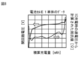
- FIG. 8 is a diagram showing an example of measured values (OCV value, resistance value) of one of two battery cells connected in parallel.
- FIG. 9 is a diagram showing an example of measured values (OCV value, resistance value) of the other battery cell alone of the two battery cells connected in parallel.
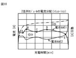
- FIG. 10 is a diagram showing an example of a simulation result (current value, voltage value) of a battery module in which two battery cells are connected in parallel (two-parallel module).
- FIG. 11 is a diagram showing an example of actual measured values (current values, voltage values) of a battery module in which two battery cells are connected in parallel (two-parallel module).
- FIG. 12 is a diagram showing an example of a simulation result (OCV value, initial resistance value) of a battery module in which two battery cells are connected in parallel (two-parallel module).
- FIG. 13 is a diagram showing an example of a simulation result (ODD terms and RBD terms) of a battery module in which two battery cells are connected in parallel (two-parallel module).
- FIG. 14 is a diagram showing an example of a battery module in which three battery cells are connected in parallel (a three-parallel module).
- FIG. 15 is a diagram showing a two-parallel module in which the second and third battery cells in the battery module of FIG. 14 are regarded as one battery cell.
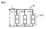
- FIG. 16 is a diagram showing a two-parallel module in which the first and third battery cells in the battery module of FIG. 14 are regarded as one battery cell.
- FIG. 17 is a diagram showing a two-parallel module in which the first and second battery cells in the battery module of FIG. 13 are regarded as one battery cell.
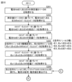
- FIG. 18 is a diagram showing a procedure for estimating the charging current value of the three battery cells constituting the battery module of FIG. 14 in the charging current value estimation system of FIG.
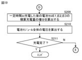
- FIG. 19 is a diagram showing the procedure following "D" in FIG.
- FIG. 11 is a diagram illustrating an example of a functional block of a charging current value estimation system according to a second embodiment of the present technology.
- FIG. 1(A) shows an example of a conventional battery cell model.
- FIG. 1(B) shows a model of a battery cell used in the present technology.
- the battery cell may be described by two elements, an internal resistance R and a voltage source E (FIG. 1(A)).
- the voltage source E which represents the electromotive force component, can input and output electric charge unlimitedly, this model cannot reproduce the manner in which the open circuit voltage changes due to charging and discharging.
- the model of FIG. 1(B) is used, which uses a capacitor C instead of the voltage source E.
- a battery module M in which n (n is a natural number of 2 or more) battery cells are connected in parallel will be described.
- Fig. 2 shows an example of a battery module M used in the present technology.
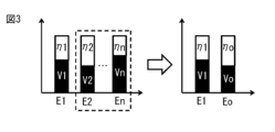
- Fig. 3 shows an example of voltages generated in each of the battery cells E1, E2, ..., En of the battery module M shown in Fig. 2.
- Each of the battery cells E1, E2, ..., En is represented by the model shown in Fig. 1(B).
- each of the battery cells E1, E2, ..., En is a lithium-ion secondary battery.
- the battery cells shown in Figs. 1(A) and 1(B) may be unit cells, battery blocks in which multiple unit cells are connected, or assembled batteries in which a battery block and accessories are integrally packed. In an assembled battery, multiple lithium-ion secondary batteries are connected in series. The assembled battery may also include multiple lithium-ion secondary batteries electrically connected in parallel.
- a block in which the second to n-th battery cells E2, ..., En are connected in parallel is regarded as one large battery cell Eo, and two battery cells E1, Eo are considered to be connected in parallel as a battery module M (FIG. 2).
- the open circuit voltage is Vo
- the internal resistance is Ro
- the differential capacity is Co.
- the sum of the current distribution ratios ⁇ i ( ⁇ 1+ ⁇ o) is 1 (equation (4)), and the following equation (5) is established.
- ⁇ 1+ ⁇ o 1...(4)
- equation (10) is obtained.
- ⁇ V (Ro ⁇ o ⁇ R1 ⁇ 1) ⁇ I...(9)
- ⁇ 1 (Ro/Ra) ⁇ ( ⁇ V/(Ra ⁇ I))...(10)
- the first term on the right hand side of equation (10) is called the RBD term (Resistance Balance Dependent Term) because it is a component determined by the balance of resistance values in the current distribution ratio.
- the second term on the right hand side of equation (10) is called the ODD term (OCV Difference Dependent Term) because it is a component determined by the difference in open circuit voltages.
- the first term on the right-hand side of equation (10) indicates that the current distribution ratio depends on the balance of internal resistance.
- Equation (17) is an analytical solution of the current distribution ratio taking into consideration the passage of time.
- equations (18) and (19) hold true.
- formulas (4) to (20) it is possible to replace battery cell Eo with the same type of battery cell as battery cell E1. In other words, formulas (4) to (20) also hold for a two-parallel battery module in which two battery cells E1 and E2 are connected in parallel. In this case, in formulas (4) to (20), ⁇ o should be replaced with ⁇ 2, Vo with V2, ⁇ o with ⁇ 2, Ro with R2, Co with C2, and ⁇ Vo with ⁇ V2.
- a charging current value estimation system for estimating charging current values I1, I2 of each battery cell E1, E2 in a battery module (two-parallel module) in which the battery cells E1, E2 shown in Fig. 2 are connected in parallel
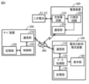
- Fig. 4 shows an example of a schematic configuration of the charging current value estimation system.
- the charging current value estimation system includes, for example, a charging current value estimation device 100, a server device 200, and a power supply device 300 as shown in Fig. 4.
- the charging current value estimation device 100, the server device 200, and the power supply device 300 are capable of communicating with each other via a communication network 400.
- the communication network 400 includes, for example, the Internet, a cloud network, or a network specific to a business operator.
- Battery cell E1 or battery cell E2 is connected to power supply device 300.
- Power supply device 300 is a device that charges and discharges battery cell E1 or battery cell E2, and is a network communication type device that has the function of communicating with external devices.
- Power supply device 200 has, for example, a charge/discharge circuit 310, an IV measurement circuit 320, and a communication unit 330.
- the charge/discharge circuit 310 charges or discharges the battery cell E1 or the battery cell E2.
- the charge/discharge circuit 310 charges or discharges in an OCV (Open Circuit Voltage) measurement mode or a CCV (Closed Circuit Voltage) measurement mode.
- OCV Open Circuit Voltage
- CCV Cell Voltage
- the charge/discharge circuit 310 performs intermittent charging, for example, after completely discharging the battery cell E1 or the battery cell E2.
- the charge/discharge circuit 310 performs intermittent charging, for example, by repeating 0.5C charging for 6 minutes and a pause for 30 minutes.
- the charge/discharge circuit 310 performs constant current charging at 1C, for example, after completely discharging the battery cell E1 or the battery cell E2.
- the IV measurement circuit 320 measures the voltage and current of battery cell E1 or battery cell E2.
- the IV measurement circuit 320 obtains a measurement value D1 by measuring the voltage and current of battery cell E1 in the OCV measurement mode.
- the IV measurement circuit 320 obtains a measurement value D2 by measuring the voltage and current of battery cell E1 in the CCV measurement mode.
- the IV measurement circuit 320 obtains a measurement value D3 by measuring the voltage and current of battery cell E2 in the OCV measurement mode.
- the IV measurement circuit 320 obtains a measurement value D4 by measuring the voltage and current of battery cell E2 in the CCV measurement mode.
- the IV measurement circuit 320 outputs the measurement values D1, D2, D3, and D4 obtained by the measurements to the server device 200 via the communication unit 330.
- the communication unit 330 is a communication interface that communicates with the server device 200 via the communication network 400.
- the communication unit 330 transmits the measurement values D1, D2, D3, and D4 obtained by the IV measurement circuit 320 to the server device 200 via the communication network 400.
- the server device 200 has, for example, a communication unit 210, a control unit 220, and a memory unit 230.
- the communication unit 210 is a communication interface that communicates with the power supply device 300 or the charging current value estimation device 100 via the communication network 400.
- the communication unit 210 receives the measurement values D1, D2, D3, and D4 from the power supply device 300 via the communication network 400, and outputs them to the control unit 220.
- the communication unit 210 transmits the measurement values D1, D2, D3, and D4 input from the control unit 220 to the charging current value estimation device 100 via the communication network 400.
- the control unit 220 includes, for example, a central processing unit (CPU).
- the control unit 220 stores the measurement values D1, D2, D3, and D4 acquired from the power supply device 300 via the communication unit 210 in the memory unit 230.
- the memory unit 230 includes, for example, a non-volatile memory such as a flash memory.
- the measurement values D1, D2, D3, and D4 acquired from the power supply device 300 are stored in the memory unit 230.
- the control unit 220 reads out the measurement values D1, D2, D3, and D4 from the memory unit 230 and outputs them to the charging current value estimation device 100 via the communication unit 210.
- the charging current value estimation device 100 has, for example, a communication unit 110, a data processing unit 120, a storage unit 130, and a display unit 140.
- the communication unit 110 is a communication interface that communicates with the server device 200 via the communication network 400.
- the communication unit 110 receives measurement values D1, D2, D3, and D4 from the server device 200 via the communication network 400, and outputs them to the data processing unit 120.
- the data processing unit 120 includes, for example, a central processing unit (CPU).
- the data processing unit 120 estimates the charging current values I1 and I2 of each battery cell E1, E2 in a battery module (two parallel modules) in which the battery cells E1, E2 are connected in parallel based on the measured values D1, D2, D3, and D4 acquired from the server device 200.
- the data processing unit 120 generates a video signal for displaying an image including the charging current values I1 and I2 of each battery cell E1, E2 obtained by estimation, and outputs the video signal to the display unit 140.
- the display unit 140 includes, for example, a liquid crystal panel or an organic EL panel.
- the display unit 140 displays an image based on the video signal input from the data processing unit 120.
- the storage unit 130 includes, for example, a central processing unit (CPU).
- the storage unit 130 stores various data generated by the data processing unit 120.
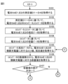
- Fig. 5 shows an example of the procedure for calculating the charging current values I1, I2 of the battery cells E1, E2.
- Fig. 6 shows an example of the procedure following "A” in Fig. 5.
- Fig. 7 shows an example of the procedure following "B” in Fig. 5.
- the data processing unit 120 first acquires the measurement values D1, D2, D3, and D4 of the battery cells E1 and E2 from the server device 200 (step S101).
- the data processing unit 120 generates data on the OCV of the battery cell E1 (OCV data Da) based on the acquired measurement value D1, and stores the data in the memory unit 130 (step S102).
- the data processing unit 120 generates the OCV data Da, for example, by using the measurement value D1 to associate the final voltage V of each pause period of the intermittent charging with the accumulated charge amount Q up to the final timing of each pause period of the intermittent charging.
- the OCV data Da is data that indicates the relationship between the OCV and the accumulated charge amount Q in the battery cell E1.
- the data processing unit 120 generates data (CCV data Db) about the CCV of the battery cell E1 based on the acquired measurement value D2, and stores the data in the memory unit 130 (step S102).
- the data processing unit 120 generates the CCV data Db, for example, by using the measurement value D2 to associate the voltage V at each predetermined timing with the accumulated charge amount Q up to the predetermined timing.
- the CCV data Db is data that indicates the relationship between the CCV and the accumulated charge amount Q in the battery cell E1.
- the data processing unit 120 generates data (OCV data Dc) about the OCV of the battery cell E2 based on the acquired measurement value D3, and stores the data in the memory unit 130 (step S102).
- the data processing unit 120 generates the OCV data Dc, for example, by using the measurement value D3 to associate the final voltage V of each pause period of the intermittent charging with the accumulated charge amount Q up to the final timing of each pause period of the intermittent charging.
- the OCV data Dc is data that indicates the relationship between the OCV and the accumulated charge amount Q in the battery cell E2.
- the data processing unit 120 generates data (CCV data Dd) about the CCV of the battery cell E2 based on the acquired measurement value D4, and stores the data in the memory unit 130 (step S102).
- the data processing unit 120 generates the CCV data Dd, for example, by using the measurement value D4 to associate the voltage V at each predetermined timing with the accumulated charge amount Q up to the predetermined timing.
- the CCV data Dd is data that indicates the relationship between the CCV and the accumulated charge amount Q in the battery cell E2.
- the data processing unit 120 generates data (resistance data De) on the resistance value R1 of the battery cell E1 based on the OCV data Da and CCV data Db of the battery cell E1, and stores the data in the memory unit 130 (step S103). For example, the data processing unit 120 generates the resistance data De by subtracting the OCV value of the OCV data Da from the CCV value of the CCV data Db for each accumulated charge amount Q, and dividing the resulting value (CCV value - OCV value) by the current value at the time the CCV data was obtained.
- the resistance data De is data that indicates the relationship between the resistance value R1 of the battery cell E1 and the accumulated charge amount Q. If the OCV data Da and the CCV data Db do not contain values at the same accumulated charge amount Q, the data processing unit 120 may appropriately perform data interpolation using an interpolation algorithm such as the B-Spline method.
- the data processing unit 120 generates data (resistance data Df) on the resistance value R2 of the battery cell E2 based on the OCV data Dc and CCV data Dd of the battery cell E2, and stores the data in the storage unit 130 (step S103). For example, the data processing unit 120 generates the resistance data Df by subtracting the OCV value of the OCV data Dc from the CCV value of the CCV data Dd for each accumulated charge amount Q, and dividing the resulting value (CCV value - OCV value) by the current value at the time the CCV data was obtained.
- the resistance data Df is data that indicates the relationship between the resistance value R2 of the battery cell E2 and the accumulated charge amount Q. If the OCV data Dc and the CCV data Dd do not contain values at the same accumulated charge amount Q, the data processing unit 120 may appropriately perform data interpolation using an interpolation algorithm such as the B-Spline method.
- the data processing unit 120 generates capacitance data (capacity data Dg) for the capacity value C1 of the battery cell E1 based on the OCV data Da, and stores it in the storage unit 130 (step S104).
- the data processing unit 120 generates the capacity data Dg by numerically differentiating the OCV data Da. For example, the data processing unit 120 extracts the OCV value at a certain integrated charge amount Qk and the OCV value at an integrated charge amount Qk+ ⁇ Q from the OCV data Da, calculates the difference between the two extracted values, and divides ⁇ Q by the value obtained thereby to obtain the capacity value C1 at a certain integrated charge amount Qk. For example, the data processing unit 120 calculates the capacity value C1 at each integrated charge amount Q included in the OCV data Da. When calculating the capacity value C1, the data processing unit 120 may appropriately perform data interpolation using an interpolation algorithm such as the B-Spline method.
- the data processing unit 120 generates data (capacity data Dh) on the capacity value C2 of the battery cell E2 based on the OCV data Dc, and stores it in the storage unit 130 (step S104).
- the data processing unit 120 generates the capacity data Dh by numerically differentiating the OCV data Dc. For example, the data processing unit 120 extracts the OCV value at a certain integrated charge amount Qk and the OCV value at an integrated charge amount Qk+ ⁇ Q from the OCV data Dc, calculates the difference between the two extracted values, and divides ⁇ Q by the value obtained thereby to obtain the capacity value C2 at a certain integrated charge amount Qk. For example, the data processing unit 120 calculates the capacity value C2 at each integrated charge amount Q included in the OCV data Dc. When calculating the capacity value C2, the data processing unit 120 may appropriately perform data interpolation using an interpolation algorithm such as the B-Spline method.
- the data processing unit 120 obtains an OCV value V1 for a certain accumulated charge amount Q1 of the battery cell E1 from the OCV data Da (step S105).
- the data processing unit 120 obtains an OCV value V1 for a certain accumulated charge amount Q2 of the battery cell E2 from the OCV data Dc (step S105).
- the data processing unit 120 obtains a resistance value R1 for a certain accumulated charge amount Q1 of the battery cell E1 from the resistance data De (step S105).
- the data processing unit 120 obtains a resistance value R2 for a certain accumulated charge amount Q2 of the battery cell E2 from the resistance data Df (step S105).
- the data processing unit 120 obtains a capacitance value C1 for a certain accumulated charge amount Q1 of the battery cell E1 from the numerical differentiation of the OCV data Da (step S106).
- the data processing unit 120 obtains the capacity value C2 of the battery cell E2 for a certain accumulated charge amount Q2 from the numerical differentiation of the OCV data Dc (step S106).
- the data processing unit 120 determines whether the difference ⁇ C between the capacity value C1 of the battery cell E1 and the capacity value C2 of the battery cell E1 at a certain accumulated charge amount Q1, Q2 is greater than a predetermined threshold value (step S107). As a result, if the difference ⁇ C is greater than the predetermined threshold value (step S107; Y), the process proceeds to step S108. If the difference ⁇ C is equal to or less than the predetermined threshold value (step S107; N), the process proceeds to step S112.
- the data processing unit 120 executes steps S105, S106, and S107 for the second or subsequent time, it sets the accumulated charge amounts Q1 and Q2 calculated in step S109 or step S113, described below, as the "certain accumulated charge amounts Q1 and Q2". Note that the data processing unit 120 may set any charge amounts as the initial charge amounts Q1 and Q2.
- step S108 the data processing unit 120 substitutes the numerical values (OCV values V1, V2, resistance values R, R2, and capacitance values C1, C2 for the accumulated charge amounts Q1, Q2 of the battery cells E1, E2) acquired in steps S105 and S106 into equation (17) to calculate a current distribution ratio ⁇ 1 for the accumulated charge amount Q1 of the battery cell E1 (step S108).
- the data processing unit 120 further substitutes the calculated current distribution ratio ⁇ 1 into the following equation (21) to calculate a current distribution ratio ⁇ 2 for the accumulated charge amount Q2 of the battery cell E2 (step S108).
- the data processing unit 120 calculates the current values (charging current values I1, I2) flowing through each of the battery cells E1, E2 (step S108).
- the data processing unit 120 calculates the charging current values I1, I2 flowing through each of the battery cells E1, E2, for example, using the following equations (22) and (23).
- the data processing unit 120 calculates increments ⁇ Q1, ⁇ Q2 of the integrated charge amounts Q1, Q2 of the battery cells E1, E2 after charging for a time period ⁇ t (step S109).
- the data processing unit 120 calculates the increment ⁇ Q1 of the integrated charge amount Q1 of the battery cell E1, for example, by substituting the charging current value I1 and the time period ⁇ t into the following equation (24).
- the data processing unit 120 calculates the increment ⁇ Q2 of the integrated charge amount Q2 of the battery cell E2, for example, by substituting the charging current value I2 and the time period ⁇ t into the following equation (25).
- ⁇ Q1 I1 ⁇ t...(24)
- ⁇ Q2 I2 ⁇ t...(25)
- the data processing unit 120 calculates the voltage Va of the entire battery module M in which the battery cells E1 and E2 are connected in parallel (step S110).
- the data processing unit 120 calculates the open circuit voltage value Vx of the battery cell E1 at the integrated charge amount Q1 by, for example, adding the value obtained by multiplying the resistance value R1 of the battery cell E1 at the integrated charge amount Q1 and the current I1 to the OCV value V1 of the battery cell E1 at the integrated charge amount Q1.
- the data processing unit 120 calculates the voltage value Vy of the battery cell E2 at the integrated charge amount Q2 by, for example, adding the value obtained by multiplying the resistance value R2 of the battery cell E2 at the integrated charge amount Q2 and the current I2 to the OCV value V2 of the battery cell E2 at the integrated charge amount Q2. For example, the data processing unit 120 estimates the average value ((Vx+Vy)/2) of the voltage value Vx of the battery cell E1 and the voltage value Vy of the battery cell E2 as the voltage value of the entire battery module M.
- the data processing unit 120 may calculate the internal resistance of the entire battery module M in which the battery cells E1 and E2 are connected in parallel, as necessary.
- the data processing unit 120 determines whether charging of the battery module M is complete (step S111). If the voltage value of the entire battery module M is equal to or greater than a predetermined threshold (step S111; Y), the data processing unit 120 determines that charging of the battery module M is complete and ends the process. If the voltage value of the entire battery module M is less than the predetermined threshold (step S111; N), the data processing unit 120 determines that charging of the battery module M is not complete and returns to step S105.
- step S107 If the difference ⁇ C is equal to or less than the predetermined threshold in step S107 (step S107; N), the data processing unit 120 proceeds to step S112.
- step S112 the data processing unit 120 calculates the current distribution ratio ⁇ 1 for the integrated charge amount Q1 of the battery cell E1 by substituting the numerical values acquired in steps S105 and S106 (OCV values V1, V2 and resistance values R, R2 for the integrated charge amounts Q1, Q2 of the battery cells E1, E2) into equation (10) (step S112).
- the data processing unit 120 further calculates the current distribution ratio ⁇ 2 for the integrated charge amount Q2 of the battery cell E2 by substituting the calculated current distribution ratio ⁇ 1 into equation (21) (step S112).
- the data processing unit 120 calculates increments ⁇ Q1, ⁇ Q2 of the integrated charge amounts Q1, Q2 of the battery cells E1, E2 after charging for a time period ⁇ t (step S113).
- the data processing unit 120 calculates the increment ⁇ Q1 of the integrated charge amount Q1 of the battery cell E1, for example, by substituting the charging current value I1 and the time period ⁇ t into the following equation (27).
- the data processing unit 120 calculates the increment ⁇ Q2 of the integrated charge amount Q2 of the battery cell E2, for example, by substituting the charging current value I2 and the time period ⁇ t into the following equation (28).
- ⁇ Q1 I1 ⁇ t...(27)
- ⁇ Q2 I2 ⁇ t...(28)
- the data processing unit 120 calculates the voltage Va of the entire battery module M in which the battery cells E1 and E2 are connected in parallel (step S114). For example, the data processing unit 120 calculates the voltage value Vx of the battery cell E1 at the integrated charge amount Q1 by adding a value obtained by multiplying the resistance value R1, the current I, and the current distribution ratio ⁇ 1 of the battery cell E1 at the integrated charge amount Q1 to the OCV value V1 of the battery cell E1 at the integrated charge amount Q1 (equation (29)).
- the data processing unit 120 calculates the voltage value Vy of the battery cell E2 at the integrated charge amount Q2 by adding a value obtained by multiplying the resistance value R2, the current I, and the current distribution ratio ⁇ 2 of the battery cell E2 at the integrated charge amount Q2 to the OCV value V2 of the battery cell E2 at the integrated charge amount Q2 (equation (30)).
- the data processing unit 120 estimates, for example, the average value ((Vx+Vy)/2) of the voltage value Vx of the battery cell E1 and the voltage value Vy of the battery cell E2 as the voltage Va of the entire battery module M (equation (31)).
- Vx V1+R1 ⁇ I ⁇ 1...(29)
- Vy V2+R2 ⁇ I ⁇ 2...(30)
- Va (Vx+Vy)/2...(31)
- the data processing unit 120 may calculate the internal resistance Ra of the entire battery module M in which the battery cells E1 and E2 are connected in parallel, as necessary.
- the data processing unit 120 determines whether charging of the battery module M is complete (step S115). If the voltage value Va of the entire battery module M is equal to or greater than a predetermined threshold (step S115; Y), the data processing unit 120 determines that charging of the battery module M is complete and ends the process. If the voltage value Va of the entire battery module M is less than the predetermined threshold (step S115; N), the data processing unit 120 determines that charging of the battery module M is not complete and returns to step S105.
- a new (unused) cell was prepared as the battery cell E1.
- the measured values (OCV data Da and resistance data De) obtained for this battery cell E1 are shown in Fig. 8.
- a battery cell of the same type as the battery cell E1 was prepared as the battery cell E2, which was stored in a fully charged state at high temperature (90°C, 25 days) and deteriorated.
- the measured values (OCV data Dc and resistance data Df) obtained for this battery cell E2 are shown in Fig. 9.
- Fig. 10 shows the simulation results (current values, voltage values) of each battery cell E1, E2 obtained using the data (OCV data Da, Dc and resistance data De, Df) shown in Figs. 8 and 9 in Fig. 10.
- Fig. 11 shows the actual measured current values, voltage values in a battery module (2 parallel module) in which battery cells E1, E2 having the characteristics (OCV data Da, Dc and resistance data De, Df) shown in Figs. 8 and 9 are connected in parallel.
- the simulation results (OCV value, initial resistance value) of each battery cell E1, E2 obtained using the data (OCV data Da, Dc and resistance data De, Df) shown in Figures 8 and 9 are shown in Figure 12. Also, in the charging current value estimation system according to this embodiment, the simulation results (ODD term, RBD term) of battery cell E1 obtained using the data (OCV data Da, Dc and resistance data De, Df) shown in Figures 8 and 9 are shown in Figure 13.
- the OCV of battery cell E2 is elongated overall in the time axis direction compared to the OCV of battery cell E1, and as a result, there are locations where a difference occurs between the OCV of battery cell E2 and the OCV of battery cell E1. Also, from Figure 12, it can be seen that near the end of charging (point E), a difference occurs between the OCV of battery cell E2 and the OCV of battery cell E1 due to a step seen in the OCV of battery cell E1. Also, from Figure 12, it can be seen that, regarding the initial resistance value, the difference between battery cell E1 and battery cell E2 is roughly constant regardless of the charging time, but that there is a complex change between the beginning and end of the charging time.
- the sum of the ODD value and the RBD value corresponds to the current distribution ratio of battery cell E1, and the value obtained by multiplying the current distribution ratio of battery cell E1 by the value of the current flowing through the entire two-parallel module is the current value distributed to battery cell E1. From Figure 13, it was confirmed that the timing of the minimum point of the RBD value at the beginning of charging coincides with the timing of the minimum point of the initial resistance value in Figure 12. From this, it is presumed that the cause of the RBD value becoming a minimum value at the beginning of charging is the balance of the internal resistance of battery cell E1.
- P1 is located near the maximum value of the ODD value and the maximum value of the RBD value, and it was confirmed that the current value distributed to battery cell E1 at P1 is a maximum value. It is presumed that the current value distributed to battery cell E1 at P1 is a maximum value due to the influence of both ODD and RBD.
- P2 is located near the minimum value of the ODD value and the minimum value of the RBD value, and it was confirmed that the current value distributed to battery cell E1 at P2 is a minimum value. It is presumed that the reason the current value distributed to battery cell E1 at P2 is a minimum value is due to the large difference between ODD and RBD.
- P3 is located near the maximum value of the ODD value and the maximum value of the RBD value, and it was confirmed that the current value distributed to battery cell E1 at P3 is a maximum value. It is presumed that the current value distributed to battery cell E1 at P3 is a maximum value due to the influence of both ODD and RBD.
- the charging current value of each battery cell E1, E2 is calculated based on the open circuit voltage data for the integrated charge amount Q1, Q2 of each battery cell E1, E2 and the cell resistance data for the integrated charge amount Q1, Q2 of each battery cell E1, E2. This allows the calculation results to match well with the actual measurement results.
- the integrated charge amount (charge amount after ⁇ t) of each battery cell E1, E2 after a time of ⁇ t has elapsed is derived based on the charge current value at the initial charge amount of each battery cell E1, E2.
- the open circuit voltage value for the integrated charge amount (charge amount after ⁇ t) of each battery cell E1, E2 is derived from the open circuit voltage data
- the resistance value for the integrated charge amount (charge amount after ⁇ t) of each battery cell E1, E2 is derived from the cell resistance data
- the capacity value for the integrated charge amount (charge amount after ⁇ t) of each battery cell E1, E2 is derived from the capacitance data.
- the charge current value of each battery cell E1, E2 when the charge amount of each battery cell E1, E2 is the integrated charge amount (charge amount after ⁇ t) is calculated based on the open circuit voltage value, resistance value, and capacity value at the initial charge amount and the integrated charge amount (charge amount after ⁇ t). This allows the calculation result to match the actual measurement result with even greater accuracy.
- each time ⁇ t passes the integrated charge amount (charge amount after ⁇ t has passed), open circuit voltage value, resistance value, capacity value, and charging current value of each battery cell E1, E2 are calculated. This allows the calculated results to match the actual measured results with even greater accuracy.
- the charging current value of each battery cell E1, E2 when the charge amount of each battery cell E1, E2 is the accumulated charge amount (charge amount after ⁇ t has elapsed) is calculated based on a calculation formula for the charging current value of each battery cell E1, E2, which is obtained by regarding each battery cell E1, E2 as an equivalent circuit including a series-connected capacity Ca and internal resistance R, and the open circuit voltage value, resistance value, and capacity value at the initial charge amount and the accumulated charge amount (charge amount after ⁇ t has elapsed). This makes it possible to more accurately match the calculation result with the actual measurement result.
- the charging current values of the two battery cells E1, E2 included in the two-parallel module are calculated.
- the charging current values of the three battery cells E1, E2, E3 included in a battery module (three-parallel module) in which three battery cells E1, E2, E3 are connected in parallel as shown in FIG. 14 may be calculated.
- the three-parallel module is converted into the following three types of two-parallel modules:
- a first two-parallel module in which two battery cells E1 and Eo1 are connected in parallel (FIG. 15)
- a second two-parallel module in which two battery cells E2 and Eo2 are connected in parallel (FIG. 16)
- a third two-parallel module in which two battery cells E3 and Eo3 are connected in parallel (FIG. 17)
- Fig. 18 shows an example of the procedure for calculating the charging current values I1, I2, and I3 of the three battery cells E1, E2, and E3.
- Fig. 19 shows an example of the procedure following "D" in Fig. 18.
- the data processing unit 120 first obtains the measurement values D1, D2, D3, D4, D5, and D6 of the battery cells E1, E2, and E3 from the server device 200 (step S201).
- Measured value D1 is a measured value obtained in the IV measurement circuit 320 by measuring the voltage and current of battery cell E1 in the OCV measurement mode.
- Measured value D2 is a measured value obtained in the IV measurement circuit 320 by measuring the voltage and current of battery cell E1 in the CCV measurement mode.
- Measured value D3 is a measured value obtained in the IV measurement circuit 320 by measuring the voltage and current of battery cell E2 in the OCV measurement mode.
- Measured value D4 is a measured value obtained in the IV measurement circuit 320 by measuring the voltage and current of battery cell E2 in the CCV measurement mode.
- Measured value D5 is a measured value obtained in the IV measurement circuit 320 by measuring the voltage and current of battery cell E3 in the OCV measurement mode.
- Measured value D6 is a measured value obtained in the IV measurement circuit 320 by measuring the voltage and current of battery cell E3 in the CCV measurement mode.
- the data processing unit 120 generates data (OCV data Da) about the OCV of the battery cell E1 based on the acquired measurement value D1, and stores the data in the memory unit 130 (step S202). For example, the data processing unit 120 generates the OCV data Da by using the measurement value D1 to associate the final voltage V of each pause period of the intermittent charging with the accumulated charge amount Q up to the final timing of each pause period of the intermittent charging.
- the OCV data Da is data that indicates the relationship between the OCV and the accumulated charge amount Q in the battery cell E1.
- the data processing unit 120 generates data (CCV data Db) about the CCV of the battery cell E1 based on the acquired measurement value D2, and stores the data in the memory unit 130 (step S202).
- the data processing unit 120 generates the CCV data Db, for example, by using the measurement value D2 to associate the voltage V at each predetermined timing with the accumulated charge amount Q up to the predetermined timing.
- the CCV data Db is data that indicates the relationship between the CCV and the accumulated charge amount Q in the battery cell E1.
- the data processing unit 120 generates data (OCV data Dc) about the OCV of the battery cell E2 based on the acquired measurement value D3, and stores the data in the memory unit 130 (step S202). For example, the data processing unit 120 generates the OCV data Dc by using the measurement value D3 to associate the final voltage V of each pause period of the intermittent charging with the accumulated charge amount Q up to the final timing of each pause period of the intermittent charging.
- the OCV data Dc is data that indicates the relationship between the OCV and the accumulated charge amount Q in the battery cell E2.
- the data processing unit 120 generates data (CCV data Dd) about the CCV of the battery cell E2 based on the acquired measurement value D4, and stores the data in the memory unit 130 (step S202).
- the data processing unit 120 generates the CCV data Dd, for example, by using the measurement value D4 to associate the voltage V at each predetermined timing with the accumulated charge amount Q up to the predetermined timing.
- the CCV data Dd is data that indicates the relationship between the CCV and the accumulated charge amount Q in the battery cell E2.
- the data processing unit 120 generates data (OCV data Di) on the OCV of the battery cell E3 based on the acquired measurement value D5, and stores the data in the memory unit 130 (step S202). For example, the data processing unit 120 generates the OCV data Di by using the measurement value D5 to associate the final voltage V of each pause period of the intermittent charging with the accumulated charge amount Q up to the final timing of each pause period of the intermittent charging.
- the OCV data Di is data that indicates the relationship between the OCV and the accumulated charge amount Q in the battery cell E3.
- the data processing unit 120 generates data (CCV data Dj) about the CCV of the battery cell E3 based on the acquired measurement value D6, and stores the data in the memory unit 130 (step S202).
- the data processing unit 120 generates the CCV data Dj, for example, by using the measurement value D6 to associate the voltage V at each predetermined timing with the accumulated charge amount Q up to the predetermined timing.
- the CCV data Dj is data that indicates the relationship between the CCV and the accumulated charge amount Q in the battery cell E3.
- the data processing unit 120 generates data (resistance data De) on the resistance value R1 of the battery cell E1 based on the OCV data Da and CCV data Db of the battery cell E1, and stores the data in the memory unit 130 (step S203). For example, the data processing unit 120 generates the resistance data De by subtracting the OCV value of the OCV data Da from the CCV value of the CCV data Db for each accumulated charge amount Q, and dividing the resulting value (CCV value - OCV value) by the current value at the time the CCV data was obtained.
- the resistance data De is data that indicates the relationship between the resistance value R1 of the battery cell E1 and the accumulated charge amount Q. If the OCV data Da and the CCV data Db do not contain values at the same accumulated charge amount Q, the data processing unit 120 may appropriately perform data interpolation using an interpolation algorithm such as the B-Spline method.
- the data processing unit 120 generates data (resistance data Df) on the resistance value R2 of the battery cell E2 based on the OCV data Dc and CCV data Dd of the battery cell E2, and stores the data in the memory unit 130 (step S203). For example, the data processing unit 120 generates the resistance data Df by subtracting the OCV value of the OCV data Dc from the CCV value of the CCV data Dd for each accumulated charge amount Q, and dividing the resulting value (CCV value - OCV value) by the current value at the time the CCV data was obtained.
- the resistance data Df is data that indicates the relationship between the resistance value R2 of the battery cell E2 and the accumulated charge amount Q. If the OCV data Dc and the CCV data Dd do not contain values at the same accumulated charge amount Q, the data processing unit 120 may appropriately perform data interpolation using an interpolation algorithm such as the B-Spline method.
- the data processing unit 120 generates data (resistance data Dk) on the resistance value R3 of the battery cell E3 based on the OCV data Di and CCV data Dj of the battery cell E3, and stores the data in the storage unit 130 (step S203). For example, the data processing unit 120 generates the resistance data Dk by subtracting the OCV value of the OCV data Dj from the CCV value of the CCV data Di for each accumulated charge amount Q, and dividing the resulting value (CCV value - OCV value) by the current value at the time the CCV data was obtained.
- the resistance data Dk is data that indicates the relationship between the resistance value R3 of the battery cell E3 and the accumulated charge amount Q. If the OCV data Di and the CCV data Dj do not contain values at the same accumulated charge amount Q, the data processing unit 120 may appropriately perform data interpolation using an interpolation algorithm such as the B-Spline method.
- the data processing unit 120 generates capacitance data (capacity data Dg) for the capacity value C1 of the battery cell E1 based on the OCV data Da, and stores it in the storage unit 130 (step S204).
- the data processing unit 120 generates the capacity data Dg by numerically differentiating the OCV data Da. For example, the data processing unit 120 extracts the OCV value at a certain integrated charge amount Qk and the OCV value at an integrated charge amount Qk+ ⁇ Q from the OCV data Da, calculates the difference between the two extracted values, and divides ⁇ Q by the value obtained thereby to obtain the capacity value C1 at a certain integrated charge amount Qk. For example, the data processing unit 120 calculates the capacity value C1 at each integrated charge amount Q included in the OCV data Da. When calculating the capacity value C1, the data processing unit 120 may appropriately perform data interpolation using an interpolation algorithm such as the B-Spline method.
- the data processing unit 120 generates data (capacity data Dh) on the capacity value C2 of the battery cell E2 based on the OCV data Dc, and stores it in the storage unit 130 (step S204).
- the data processing unit 120 generates the capacity data Dh by numerically differentiating the OCV data Dc. For example, the data processing unit 120 extracts the OCV value at a certain integrated charge amount Qk and the OCV value at an integrated charge amount Qk+ ⁇ Q from the OCV data Dc, calculates the difference between the two extracted values, and divides ⁇ Q by the value obtained thereby to obtain the capacity value C2 at a certain integrated charge amount Qk. For example, the data processing unit 120 calculates the capacity value C2 at each integrated charge amount Q included in the OCV data Dc. When calculating the capacity value C2, the data processing unit 120 may appropriately perform data interpolation using an interpolation algorithm such as the B-Spline method.
- the data processing unit 120 generates data (capacity data Dm) on the capacity value C3 of the battery cell E3 based on the OCV data Di and stores it in the storage unit 130 (step S204).
- the data processing unit 120 generates the capacity data Dm by numerically differentiating the OCV data Di. For example, the data processing unit 120 extracts an OCV value at a certain integrated charge amount Qk and an OCV value at an integrated charge amount Qk+ ⁇ Q from the OCV data Di, calculates the difference between the two extracted values, and divides ⁇ Q by the value obtained thereby to obtain a capacity value C3 at a certain integrated charge amount Qk. For example, the data processing unit 120 calculates the capacity value C3 at each integrated charge amount Q included in the OCV data Di. When calculating the capacity value C3, the data processing unit 120 may appropriately perform data interpolation using an interpolation algorithm such as the B-Spline method.
- the data processing unit 120 sets three two-parallel modules (a first two-parallel module (FIG. 15), a second two-parallel module (FIG. 16), and a third two-parallel module (FIG. 17)).
- the data processing unit 120 generates OCV data Dx1 and CCV data Dx2 of the battery cell Eo1 included in the first two-parallel module and stores them in the memory unit 130 (step S205).
- the data processing unit 120 generates OCV data Dy1 and CCV data Dy2 of the battery cell Eo2 included in the second two-parallel module and stores them in the memory unit 130 (step S205).
- the data processing unit 120 generates OCV data Dz1 and CCV data Dz2 for the battery cell Eo3 included in the third 2-parallel module and stores them in the memory unit 130 (step S205).
- the data processing unit 120 generates resistance data Dn for battery cell Eo1 based on the OCV data Dx1 and CCV data Dx2 for battery cell Eo1 and stores it in the memory unit 130 (step S206).
- the data processing unit 120 generates resistance data Dp for battery cell Eo2 based on the OCV data Dy1 and CCV data Dy2 for battery cell Eo2 and stores it in the memory unit 130 (step S206).
- the data processing unit 120 generates resistance data Dq for battery cell Eo3 based on the OCV data Dz1 and CCV data Dz2 for battery cell Eo3 and stores it in the memory unit 130 (step S206).
- the data processing unit 120 generates capacity data Dr of the battery cell Eo1 based on the OCV data Dx1 of the battery cell Eo1 and stores it in the storage unit 130 (step S207).
- the data processing unit 120 obtains the capacity data Dr by numerically differentiating the OCV data Dx1.
- the data processing unit 120 generates capacity data Ds of the battery cell Eo2 based on the OCV data Dy1 of the battery cell Eo2 and stores it in the storage unit 130 (step S207).
- the data processing unit 120 obtains the capacity data Ds by numerically differentiating the OCV data Dy1.
- the data processing unit 120 generates capacity data Dt of the battery cell Eo3 based on the OCV data Dz1 of the battery cell Eo3 and stores it in the storage unit 130 (step S207).
- the data processing unit 120 obtains the capacity data Dt by numerically differentiating the OCV data Dz1.
- the data processing unit 120 executes the above-mentioned steps S105 to S108 and S112 for each of the two-parallel modules (the first two-parallel module (FIG. 15), the second two-parallel module (FIG. 16), and the third two-parallel module (FIG. 17)), and calculates the current distribution ratios ⁇ 1, ⁇ 2, ⁇ 3 and the charging current values I1, I2, I3 of the three battery cells E1, E2, E3 (step S208).
- the data processing unit 120 calculates the increments ⁇ Q1, ⁇ Q2, ⁇ Q3 of the integrated charge amounts Q1, Q2, Q3 of the battery cells E1, E2, E3 after charging for a time ⁇ t (step S209).
- the data processing unit 120 calculates the increment ⁇ Q1 of the integrated charge amount Q1 of the battery cell E1, for example, by substituting the charging current value I1 and the time ⁇ t into the formula (24).
- the data processing unit 120 calculates the increment ⁇ Q2 of the integrated charge amount Q2 of the battery cell E2, for example, by substituting the charging current value I2 and the time ⁇ t into the formula (25).
- the data processing unit 120 calculates the voltage Va of the entire battery module M in which the battery cells E1, E2, and E3 are connected in parallel (step S210). For example, the data processing unit 120 calculates the voltage value Vx of the battery cell E1 at the integrated charge amount Q1 by adding a value obtained by multiplying the resistance value R1, the current I1, and the current distribution rate ⁇ 1 of the battery cell E1 at the integrated charge amount Q1 to the OCV value V1 of the battery cell E1 at the integrated charge amount Q1 (equation (29)).
- the data processing unit 120 calculates the voltage value Vy of the battery cell E2 at the integrated charge amount Q2 by adding a value obtained by multiplying the resistance value R2, the current I, and the current distribution rate ⁇ 2 of the battery cell E2 at the integrated charge amount Q2 to the OCV value V2 of the battery cell E2 at the integrated charge amount Q2 (equation (30)).
- the data processing unit 120 calculates the voltage value Vz of the battery cell E3 at the integrated charge amount Q3 by adding a value obtained by multiplying the resistance value R3, the current I, and the current distribution ratio ⁇ 3 of the battery cell E3 at the integrated charge amount Q3 to the OCV value V3 of the battery cell E3 at the integrated charge amount Q3 (equation (34)).
- the data processing unit 120 estimates, for example, the average value ((Vx+Vy+Vz)/3) of the voltage value Vx of the battery cell E1, the voltage value Vy of the battery cell E2, and the voltage value Vz of the battery cell E3 as the voltage Va of the entire battery module M (equation (35)).
- Vz V3+R3 ⁇ I ⁇ 3...(34)
- Va (Vx+Vy+Vz)/3...(35)
- the data processing unit 120 determines whether charging of the battery module M is complete (step S211). If the voltage value Va of the entire battery module M is equal to or greater than a predetermined threshold (step S211; Y), the data processing unit 120 determines that charging of the battery module M is complete and ends the process. If the voltage value Va of the entire battery module M is less than the predetermined threshold (step S211; N), the data processing unit 120 determines that charging of the battery module M is not complete and returns to step S208.
- the charging current values I1, I2, and I3 of three battery cells E1, E2, and E3 included in a battery module (three-parallel module) in which three battery cells E1, E2, and E3 are connected in parallel are calculated.
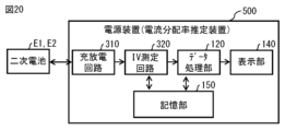
- FIG. 20 illustrates an example of a functional block of the charging current value estimation system according to the second embodiment of the present technology.
- the charging current value estimation system includes a power supply device 500, for example, as shown in Fig. 20.
- the power supply device 500 is a device that charges and discharges a battery cell E1 or a battery cell E2, and is a stand-alone device that does not have a function of communicating with an external device.
- the power supply device 500 includes a charge/discharge circuit 310, an IV measurement circuit 320, a data processing unit 120, a memory unit 150, and a display unit 140.
- the power supply device 500 (charge/discharge circuit 310) is connected to a battery cell E1 or a battery cell E2.
- the storage unit 150 is composed of a non-volatile memory such as a flash memory.
- the storage unit 150 stores the measurement values D1, D2, D3, and D4 acquired by the IV measurement circuit 320 and various data generated by the data processing unit 120.
- the power supply device 500 includes a data processing unit 120, a charge/discharge circuit 310, and an IV measurement circuit 320. This makes it possible to calculate the charging current value of each battery cell E1, E2 simply by providing the power supply device 500.
- the data processing unit 120 may be configured to calculate the charging current values of three battery cells E1, E2, E3 included in a battery module (three-parallel module) in which three battery cells E1, E2, E3 are connected in parallel, by using the method described in the modified example of the first embodiment.
- the data processing unit 120 may be configured to calculate the charging current values of n battery cells E1, E2, ..., En included in a battery module (n-parallel module) in which n battery cells E1, E2, ..., En are connected in parallel, by applying the method described in the modified example of the first embodiment.
- a charging current value estimation system capable of estimating a charging current value of each of n secondary battery cells (n being a natural number of 2 or more) when the secondary battery cells are connected in parallel to each other, comprising: a memory that stores open circuit voltage data for an integrated charge amount of each of the secondary battery cells and cell resistance data for an integrated charge amount of each of the secondary battery cells; a processing circuit capable of calculating a charging current value of each of the secondary battery cells based on the open circuit voltage data and the cell resistance data acquired from the memory;
- the processing circuitry includes: Deriving an open circuit voltage value for an initial charge amount of each of the secondary battery cells from the open circuit voltage data, and deriving a resistance value for an initial charge amount of each of the secondary battery cells from the cell resistance data; and calculating a charging current value of each of the secondary battery cells when the charge amount of each of the secondary battery cells is the initial charge amount, based on the open circuit voltage value and the resistance value.
- the memory further stores capacitance data for an integrated charge amount of each of the secondary battery cells;
- the processing circuitry includes: Deriving a charge amount after ⁇ t, which is a charge amount of each of the secondary battery cells after a time period ⁇ t has elapsed, based on a charging current value of each of the secondary battery cells at the initial charge amount; deriving an open circuit voltage value for the charge amount after ⁇ t of each of the secondary battery cells from the open circuit voltage data, deriving a resistance value for the charge amount after ⁇ t of each of the secondary battery cells from the cell resistance data, and further deriving a capacitance value for the charge amount after ⁇ t of each of the secondary battery cells from the capacitance data; and calculating a charging current value of each of the secondary battery cells when the charge amount of each of the secondary battery cells is the charge amount after ⁇ t has elapsed, based on the open circuit voltage value, the resistance value, and the capacitance value at the initial charge amount and the charge amount after ⁇ t has
- ⁇ 3> The charging current value estimation system described in ⁇ 2>, wherein the processing circuit is capable of calculating the charge amount after ⁇ t has elapsed, the open circuit voltage value, the resistance value, the capacitance value, and the charging current value of each of the secondary battery cells each time the time ⁇ t has elapsed.
- ⁇ 4> a power supply circuit capable of applying a current and a voltage to each of the secondary battery cells without connecting the secondary battery cells in parallel; a measurement circuit that measures an open circuit voltage and a constant current voltage of each of the secondary battery cells by controlling the power supply circuit;
- the charging current value estimation system according to ⁇ 2> or ⁇ 3>, wherein the processing circuit is capable of generating the open circuit voltage data, the cell resistance data, and the capacitance data based on the measurement results of the measurement circuit, and storing the data in the memory.
- the processing circuit is capable of calculating a charging current value of each of the secondary battery cells when the charge amount of each of the secondary battery cells is the charge amount after ⁇ t has elapsed, based on a calculation formula for the charging current value of each of the secondary battery cells, obtained by regarding each of the secondary battery cells as an equivalent circuit including a capacity and internal resistance connected in series, and the open circuit voltage value, the resistance value, and the capacitance value at the initial charge amount and the charge amount after ⁇ t has elapsed.
- the charging current value estimation system described in any one of ⁇ 2> to ⁇ 4>.
- a charging current value estimation method capable of estimating a charging current value of each of n secondary battery cells (where n is a natural number of 2 or more) connected in parallel to each other, comprising: Obtaining open circuit voltage data for an integrated charge amount of each of the secondary battery cells and cell resistance data for an integrated charge amount of each of the secondary battery cells; Deriving an open circuit voltage value for an initial charge amount of each of the secondary battery cells from the acquired open circuit voltage data, and deriving a resistance value for an initial charge amount of each of the secondary battery cells from the acquired cell resistance data; calculating a charging current value of each of the secondary battery cells when a charge amount of each of the secondary battery cells is the initial charge amount, based on the open circuit voltage value and the resistance value.
- ⁇ 7> Obtaining capacitance data for an integrated charge amount of each of the secondary battery cells; Deriving a charge amount after ⁇ t, which is a charge amount of each of the secondary battery cells after a time period ⁇ t has elapsed, based on a charging current value of each of the secondary battery cells at the initial charge amount; deriving an open circuit voltage value for the charge amount after ⁇ t of each of the secondary battery cells from the open circuit voltage data, deriving a resistance value for the charge amount after ⁇ t of each of the secondary battery cells from the cell resistance data, and further deriving a capacitance value for the charge amount after ⁇ t of each of the secondary battery cells from the capacitance data; and calculating a charging current value of each of the secondary battery cells when the charge amount of each of the secondary battery cells is the charge amount after ⁇ t has elapsed, based on the open circuit voltage value, the resistance value, and the capacitance value at the initial charge amount and the charge amount after ⁇ t has elapsed.
- the charging current value estimation method further comprising: calculating the charge amount after ⁇ t has elapsed, the open circuit voltage value, the resistance value, the capacitance value, and the charging current value of each of the secondary battery cells each time the time ⁇ t has elapsed.
- ⁇ 9> applying a current and a voltage to each of the secondary battery cells without connecting the secondary battery cells in parallel, thereby measuring an open circuit voltage and a constant current voltage of each of the secondary battery cells;
- the charging current value estimation method according to ⁇ 7> or ⁇ 8>, further comprising: generating the open circuit voltage data, the cell resistance data, and the capacitance data based on measurement results.
- the charging current value estimation method according to any one of ⁇ 7> to ⁇ 9>, further comprising: calculating a charging current value of each of the secondary battery cells when the charge amount of each of the secondary battery cells is the charge amount after ⁇ t has elapsed, based on a calculation formula for a charging current value of each of the secondary battery cells obtained by regarding each of the secondary battery cells as an equivalent circuit including a capacity and an internal resistance connected in series, and on the open circuit voltage value, the resistance value, and the capacitance value at the initial charge amount and the charge amount after ⁇ t has elapsed.
Landscapes
- Physics & Mathematics (AREA)
- General Physics & Mathematics (AREA)
- Engineering & Computer Science (AREA)
- Manufacturing & Machinery (AREA)
- Chemical & Material Sciences (AREA)
- Chemical Kinetics & Catalysis (AREA)
- Electrochemistry (AREA)
- General Chemical & Material Sciences (AREA)
- Secondary Cells (AREA)
Abstract
本技術の一側面に係る充電電流値推定システムは、n個(ただしnは2以上の自然数)の二次電池セルを互いに並列接続したときの各二次電池セルの充電電流値を推定することの可能なシステムである。このシステムは、各二次電池セルの積算充電量に対する開回路電圧データと、各二次電池セルの積算充電量に対するセル抵抗データとに基づいて各二次電池セルの充電電流値を算出することが可能となっている。
Description
本技術は、充電電流値推定システムおよび充電電流値推定方法に関する。
近年、リチウムイオン二次電池の用途は、電気自動車(EV)や定置型蓄電池システム(ESS)などの、より大規模な機器へと広がっている。リチウムイオン二次電池には、原料としてリチウムやコバルトなどのレアメタルが用いられている。そのため、特に大規模な機器に用いられるリチウムイオン二次電池においては、資源の有効利用の観点から中古電池パックのリパーパスやリユースが検討されている。
リパーパスとは最初の用途とは異なる用途で中古電池パックを再利用することを指す。一方、リユースとは同じ用途で中古電池パックを再利用することを指す。例えば、EVの中古電池パックをリパーパスしてESSを構築する場合など、より容量の大きな用途にて中古電池パックを再利用する場合、劣化度の互いに異なる複数の中古電池パックを組み合わせて使用する状況が生じる。
ところで、劣化度の互いに異なる複数の中古電池パックを並列接続して充電する場合、各中古電池パックに対する電流分配比が異なり、特定の中古電池パックに電流集中が生じるおそれがある。そこで、例えば、並列接続された各中古電池パックの充電電流値をシミュレーションで推定することで、特定の中古電池パックへの電流集中の有無を判定することが考えられる。充電電流値の推定については、例えば、以下の特許文献1,2に開示されている。
ところで、シミュレーションで得られる、並列接続された各中古電池パックの挙動(計算結果)と、実測で得られる、並列接続された各中古電池パックの挙動(実測結果)とが良く一致することが望まれる。従って、計算結果と実測結果とを良く一致させることの可能な充電電流値推定システムおよび充電電流値推定方法を提供することが望ましい。
本技術の第1の側面に係る充電電流値推定システムは、n個(ただしnは2以上の自然数)の二次電池セルを互いに並列接続したときの各二次電池セルの充電電流値を推定することの可能なシステムである。このシステムは、メモリおよび処理回路を備える。メモリは、各二次電池セルの積算充電量に対する開回路電圧データと、各二次電池セルの積算充電量に対するセル抵抗データとを記憶する。処理回路は、メモリから取得した開回路電圧データおよびセル抵抗データに基づいて各二次電池セルの充電電流値を算出することが可能となっている。処理回路は、以下の2つを実行することが可能となっている。
(A1)開回路電圧データから各二次電池セルの初期充電量に対する開回路電圧値を導出するとともに、セル抵抗データから各二次電池セルの初期充電量に対する抵抗値を導出すること
(A2)開回路電圧値および抵抗値に基づいて、各二次電池セルの充電量が初期充電量であるときの各二次電池セルの充電電流値を算出すること
(A1)開回路電圧データから各二次電池セルの初期充電量に対する開回路電圧値を導出するとともに、セル抵抗データから各二次電池セルの初期充電量に対する抵抗値を導出すること
(A2)開回路電圧値および抵抗値に基づいて、各二次電池セルの充電量が初期充電量であるときの各二次電池セルの充電電流値を算出すること
本技術の第2の側面に係る充電電流値推定方法は、n個(ただしnは2以上の自然数)の二次電池セルを互いに並列接続したときの各二次電池セルの充電電流値を推定することの可能な方法である。この方法は、以下の3つを含む。
(B1)各二次電池セルの積算充電量に対する開回路電圧データと、各二次電池セルの積算充電量に対するセル抵抗データとを取得すること
(B2)取得した開回路電圧データから各二次電池セルの初期充電量に対する開回路電圧値を導出するとともに、取得したセル抵抗データから各二次電池セルの初期充電量に対する抵抗値を導出すること
(B3)開回路電圧値および抵抗値に基づいて、各二次電池セルの充電量が初期充電量であるときの各二次電池セルの充電電流値を算出すること
(B1)各二次電池セルの積算充電量に対する開回路電圧データと、各二次電池セルの積算充電量に対するセル抵抗データとを取得すること
(B2)取得した開回路電圧データから各二次電池セルの初期充電量に対する開回路電圧値を導出するとともに、取得したセル抵抗データから各二次電池セルの初期充電量に対する抵抗値を導出すること
(B3)開回路電圧値および抵抗値に基づいて、各二次電池セルの充電量が初期充電量であるときの各二次電池セルの充電電流値を算出すること
本技術の第1の側面に係る充電電流値推定システム、および本技術の第2の側面に係る充電電流値推定方法では、各二次電池セルの積算充電量に対する開回路電圧データと、各二次電池セルの積算充電量に対するセル抵抗データとに基づいて各二次電池セルの充電電流値が算出される。これにより、計算結果と実測結果とを良く一致させることができる。
なお、本技術の効果は、必ずしもここで説明された効果に限定されるわけではなく、後述する本技術に関連する一連の効果のうちのいずれの効果でもよい。
以下、本技術を実施するための形態について、図面を参照して詳細に説明する。なお、説明する順序は、下記の通りである。
1.電池セルのモデル(図1)
2.電池モジュール(図2、図3)
3.時間経過を考慮しない場合の電流分配
4.時間経過を考慮した場合の電流分配
5.第1の実施の形態(図4~図13)
サーバを経由して取得した測定値を用いて、
2並列モジュールにおける充電電流値を推定する例
6.変形例(図14~図19)
3並列モジュールにおける充電電流値を推定する例
7.第2の実施の形態(図20)
電源装置単体で測定と充電電流値の推定を行う例
1.電池セルのモデル(図1)
2.電池モジュール(図2、図3)
3.時間経過を考慮しない場合の電流分配
4.時間経過を考慮した場合の電流分配
5.第1の実施の形態(図4~図13)
サーバを経由して取得した測定値を用いて、
2並列モジュールにおける充電電流値を推定する例
6.変形例(図14~図19)
3並列モジュールにおける充電電流値を推定する例
7.第2の実施の形態(図20)
電源装置単体で測定と充電電流値の推定を行う例
<1.電池セルのモデル>
まず、本技術で用いられる電池セルのモデルについて説明する。図1(A)は、従来の電池セルのモデルの一例を表したものである。図1(B)は、本技術で用いられる電池セルのモデルを表したものである。電池セルの電気的挙動を議論する際、電池セルを内部抵抗Rと電圧源Eの2つの素子で記述することがある(図1(A))。しかし、起電力成分を表す電圧源Eは電荷を無制限に出し入れすることができるため、このモデルでは、充放電によって開回路電圧が変化する様子の再現ができない。本技術では、充放電の概念を取り扱うため、電圧源Eの代わりにキャパシタCを用いた図1(B)のモデルを使用する。
まず、本技術で用いられる電池セルのモデルについて説明する。図1(A)は、従来の電池セルのモデルの一例を表したものである。図1(B)は、本技術で用いられる電池セルのモデルを表したものである。電池セルの電気的挙動を議論する際、電池セルを内部抵抗Rと電圧源Eの2つの素子で記述することがある(図1(A))。しかし、起電力成分を表す電圧源Eは電荷を無制限に出し入れすることができるため、このモデルでは、充放電によって開回路電圧が変化する様子の再現ができない。本技術では、充放電の概念を取り扱うため、電圧源Eの代わりにキャパシタCを用いた図1(B)のモデルを使用する。
理想的なキャパシタは、蓄えている電荷QがキャパシタンスCaと電圧Vとの積で記述される(Q=Ca×V)。理想キャパシタのキャパシタンスは蓄電された電荷Qに寄らず一定であるため、電荷の電圧微分であるdQ/dV値も一定であり、その値はキャパシタンスCaと等しくなる。一方で、電池のdQ/dV値は蓄電された電荷Qに依存することが知られている。すなわち、仮に縦軸をdQ/dV値として横軸を蓄電された電荷Qとしたプロットを描くと、複雑な形状となる。この、dQ/dV値が一定かどうかが、電気的に見た時のキャパシタと電池との差異である。
<2.電池モジュール>
次に、n個(ただしnは2以上の自然数)の電池セルが並列接続された電池モジュールMについて説明する。図2は、本技術で用いられる電池モジュールMの一例を表したものである。図3は、図2に記載の電池モジュールMの各電池セルE1,E2,…,Enに生じる電圧の一例を表したものである。各電池セルE1,E2,…,Enは、図1(B)に記載のモデルで表される。
次に、n個(ただしnは2以上の自然数)の電池セルが並列接続された電池モジュールMについて説明する。図2は、本技術で用いられる電池モジュールMの一例を表したものである。図3は、図2に記載の電池モジュールMの各電池セルE1,E2,…,Enに生じる電圧の一例を表したものである。各電池セルE1,E2,…,Enは、図1(B)に記載のモデルで表される。
なお、各電池セルE1,E2,…,Enは、リチウムイオン二次電池である。図1(A)、図1(B)に記載の電池セルは、単位セルであってもよく、単位セルが複数個接続された電池ブロック、もしくは、電池ブロックおよび付属品が一体的にパッキングされた組電池であってもよい。組電池では、複数のリチウムイオン二次電池が直列に接続されている。組電池内において、電気的に並列に接続された複数のリチウムイオン二次電池が含まれていてもよい。
図2において、各電池セルE1,E2,…,Enの開回路電圧はVi(1≦i≦n)、各電池セルE1,E2,…,Enの内部抵抗はRi、各電池セルE1,E2,…,EnのdQ/dV値(以下、「微分容量」と称する。)はCiであるとする。この電池モジュールMに電流Iを流した時の各電池セルE1,E2,…,Enへの電流分配率をαiとすると、各電池セルE1,E2,…,Enの過電圧ηiは、式(1)で表される。
ηi=Ri×αi×I…(1)
ηi=Ri×αi×I…(1)
電流分配率αiの総和(α1+α2+…αn)は1であり(式(2))、全ての電池セルE1,E2,…,Enは並列接続されている。そのため、各電池セルE1,E2,…,Enにおいて、開回路電圧Vnに過電圧ηiを足し合わせた端子間電圧Vの値は等しく、以下の式(3)が成り立つ。
α1+α2+…αn=1…(2)
V1+η1=V2+η2=…=Vn+ηn=V…(3)
α1+α2+…αn=1…(2)
V1+η1=V2+η2=…=Vn+ηn=V…(3)
次に、説明を単純化させるため、2番目~n番目の電池セルE2,…,Enが並列接続されたブロックを一つの大きな電池セルEoと見なして、2個の電池セルE1,Eoが並列接続された電池モジュールMであると考える(図2)。2番目の大きな電池セルEoにおいて、開回路電圧はVo、内部抵抗はRo、微分容量はCoであるとする。この場合、電流分配率αiの総和(α1+αo)は1であり(式(4))、以下の式(5)が成り立つ。
α1+αo=1…(4)
V1+η1=Vo+ηo=V…(5)
α1+αo=1…(4)
V1+η1=Vo+ηo=V…(5)
内部抵抗の算術的な総和Ra、および微分容量の算術的な総和Caは、以下の式(6)、(7)で表される。
Ra=R1+R2+…+Rn=R1+Ro…(6)
Ca=C1+C2+…+Cn=C1+Co…(7)
Ra=R1+R2+…+Rn=R1+Ro…(6)
Ca=C1+C2+…+Cn=C1+Co…(7)
<3.時間経過を考慮しない場合の電流分配>
開回路電圧V1,Voは充放電によって変化するが、まずは経過時間t=0の瞬間における電流分配について説明する。式(5)に式(1)を代入すると、以下の式(8)が得られる。
V1+R1×α1×I=Vo+Ro×αo×I…(8)
開回路電圧V1,Voは充放電によって変化するが、まずは経過時間t=0の瞬間における電流分配について説明する。式(5)に式(1)を代入すると、以下の式(8)が得られる。
V1+R1×α1×I=Vo+Ro×αo×I…(8)
ここで、開回路電圧の差ΔV=V1-Voを用いて式(8)を整理すると、以下の式(9)が得られる。更に、式(4)を用いて、αoを消去しつつ、α1についてまとめると、式(10)が得られる。
ΔV=(Ro×αo-R1×α1)×I…(9)
α1=(Ro/Ra)-(ΔV/(Ra×I))…(10)
ΔV=(Ro×αo-R1×α1)×I…(9)
α1=(Ro/Ra)-(ΔV/(Ra×I))…(10)
式(10)の右辺第1項は、電流分配率における抵抗値のバランスによって決まる成分という意味で、RBD項(Resistance Balance Dependent Term)と呼ぶことにする。式(10)の右辺第2項は、開回路電圧の差分によって決まる成分という意味で、ODD項(OCV Difference Dependent Term)と呼ぶことにする。
式(10)の右辺第1項は、電流分配分率が内部抵抗のバランスに依存していることを表している。式(10)の右辺第2項は、電流分配分率が開回路電圧の差ΔVに比例することを表している。例えば、もし内部抵抗が同一(R1=Ro、すなわちRa=2R1=2Ro)で、かつ開回路電圧も同一(ΔV=0)であった場合、これらの式を式(10)に代入するとα1=1/2となる。すなわち、2つの電池セルE1,Eoに対して等しく電流が分配される。
<4.時間経過を考慮した場合の電流分配>
次に、t秒間の充放電によって開回路電圧V1およびVoが変化する場合について説明する。まずは簡単のため、時間が経過しても電流分配分率α1,αoは変化しないと仮定し、更に、開回路電圧が変化しても微分容量C1,Coは変化しないと仮定する。電池セルAと電池セルBの微分容量はそれぞれC1、Coであることから、開回路電圧の変化量δV1およびδVoは、以下の式(11),式(12)で表される。
δV1=(αi×I×t)/C1…(11)
δVo=(αo×I×t)/Co…(12)
次に、t秒間の充放電によって開回路電圧V1およびVoが変化する場合について説明する。まずは簡単のため、時間が経過しても電流分配分率α1,αoは変化しないと仮定し、更に、開回路電圧が変化しても微分容量C1,Coは変化しないと仮定する。電池セルAと電池セルBの微分容量はそれぞれC1、Coであることから、開回路電圧の変化量δV1およびδVoは、以下の式(11),式(12)で表される。
δV1=(αi×I×t)/C1…(11)
δVo=(αo×I×t)/Co…(12)
t秒間経過による開回路電圧の差の変化量δΔVは、式(13)で表される。よってt秒後の電池セルAへの電流分配αiは、式(10)におけるΔVをΔV+δΔVに置き換えることにより、式(14)のように表現される。
δΔV=δV1-δVo=((αi/C1)-(αo/Co))×I×t…(13)
α1=(Ro/Ra)-((ΔV+δΔV)/(Ra×I))…(14)
δΔV=δV1-δVo=((αi/C1)-(αo/Co))×I×t…(13)
α1=(Ro/Ra)-((ΔV+δΔV)/(Ra×I))…(14)
式(14)に式(13)を代入すると、式(15)が得られる。式(15)において、式(4)を用いてαoを消去すると、式(16)が得られる。
α1=(Ro/Ra)-(1/(Ra×I))×{ΔV+((α1/C1)-(αo/Co))×I×t}…(15)
α1=(Ro/Ra)-(1/(Ra×I))×{ΔV+((α1/C1)-((1-α1)/Co))×I×t}…(16)
α1=(Ro/Ra)-(1/(Ra×I))×{ΔV+((α1/C1)-(αo/Co))×I×t}…(15)
α1=(Ro/Ra)-(1/(Ra×I))×{ΔV+((α1/C1)-((1-α1)/Co))×I×t}…(16)
式(16)をα1について解くと、式(17)が得られる。
α1=((Ra×C1×Co)/(Ra×C1×Co+Ca×t))×((Ro/Ra)-(ΔV/(Ra×I))+(t/(Ra×Co)))…(17)
α1=((Ra×C1×Co)/(Ra×C1×Co+Ca×t))×((Ro/Ra)-(ΔV/(Ra×I))+(t/(Ra×Co)))…(17)
式(17)が、時間経過も考慮された電流分配率の解析解である。ところで、tの値が十分に大きい場合、式(18),式(19)が成り立つ。
|Ra×C1×Co|<<|Ca×t|…(18)
|(Ro/Ra)-(ΔV/(Ra×I)|<<|t/(Ra×Co)|…(19)
|Ra×C1×Co|<<|Ca×t|…(18)
|(Ro/Ra)-(ΔV/(Ra×I)|<<|t/(Ra×Co)|…(19)
式(18),式(19)の左辺をゼロとしたものを、式(17)に代入すると、電池セルAの電流分配率α1は、式(20)で表される。すなわち、経過時間が十分に大きいと、電流分配率は電池モジュールM全体の容量におけるその電池セルの電流分配率になることがわかる。
α1=C1/Ca…(20)
α1=C1/Ca…(20)
なお、式(4)~式(20)において、電池セルEoを、電池セルE1と同種の電池セルに置き換えることが可能である。つまり、2つの電池セルE1,E2を並列接続された2並列電池モジュールに対しても、式(4)~式(20)は成り立つ。このとき、式(4)~式(20)において、αoをα2に、VoをV2に、ηoをη2に、RoをR2に、CoをC2に、δVoをδV2にそれぞれ読み替えるものとする。
<5.実施の形態>
[構成]
次に、図2に記載の電池セルE1,E2を並列接続された電池モジュール(2並列モジュール)における各電池セルE1,E2の充電電流値I1,I2を推定する充電電流値推定システムについて説明する。図4は、充電電流値推定システムの概略構成の一例を表したものである。充電電流値推定システムは、例えば、図4に示したように、充電電流値推定装置100、サーバ装置200および電源装置300を備える。充電電流値推定装置100、サーバ装置200および電源装置300は、通信ネットワーク400を介して互いに通信可能となっている。通信ネットワーク400は、例えば、インターネット、クラウドネットワーク、または、事業者固有のネットワークなどを含んで構成されている。
[構成]
次に、図2に記載の電池セルE1,E2を並列接続された電池モジュール(2並列モジュール)における各電池セルE1,E2の充電電流値I1,I2を推定する充電電流値推定システムについて説明する。図4は、充電電流値推定システムの概略構成の一例を表したものである。充電電流値推定システムは、例えば、図4に示したように、充電電流値推定装置100、サーバ装置200および電源装置300を備える。充電電流値推定装置100、サーバ装置200および電源装置300は、通信ネットワーク400を介して互いに通信可能となっている。通信ネットワーク400は、例えば、インターネット、クラウドネットワーク、または、事業者固有のネットワークなどを含んで構成されている。
電源装置300には、電池セルE1または電池セルE2が接続される。電源装置300は、電池セルE1または電池セルE2を充放電する装置であり、外部の装置と通信する機能を有するネットワーク通信型の装置である。電源装置200は、例えば、充放電回路310、IV測定回路320および通信部330を有する。
充放電回路310は、電池セルE1または電池セルE2を放電させたり、充電したりする。充放電回路310は、OCV(Open Circuit Voltage)測定モードまたはCCV(Closed Circuit Voltage)測定モードで充放電を行う。充放電回路310は、OCV測定モードにおいて、例えば、電池セルE1または電池セルE2を完全に放電した後に間欠充電を行う。充放電回路310は、OCV測定モードにおいて、例えば、6min間の0.5C充電と、30min間の休止を繰り返す間欠充電を行う。充放電回路310は、CCV測定モードにおいて、例えば、電池セルE1または電池セルE2を完全に放電した後に1Cの定電流充電を行う。
IV測定回路320は、電池セルE1または電池セルE2の電圧および電流を測定する。IV測定回路320は、OCV測定モードにおいて電池セルE1の電圧および電流を測定することにより測定値D1を取得する。IV測定回路320は、CCV測定モードにおいて電池セルE1の電圧および電流を測定することにより測定値D2を取得する。IV測定回路320は、OCV測定モードにおいて電池セルE2の電圧および電流を測定することにより測定値D3を取得する。IV測定回路320は、CCV測定モードにおいて電池セルE2の電圧および電流を測定することにより測定値D4を取得する。IV測定回路320は、測定により得られた測定値D1,D2,D3,D4を、通信部330を介してサーバ装置200に出力する。
通信部330は、通信ネットワーク400を介してサーバ装置200と通信を行う通信インターフェースである。通信部330は、IV測定回路320で得られた測定値D1,D2,D3,D4を、通信ネットワーク400を介してサーバ装置200に送信する。
サーバ装置200は、例えば、通信部210、制御部220および記憶部230を有する。通信部210は、通信ネットワーク400を介して電源装置300または充電電流値推定装置100と通信を行う通信インターフェースである。通信部210は、電源装置300から、通信ネットワーク400を介して測定値D1,D2,D3,D4を受信し、制御部220に出力する。通信部210は、制御部220から入力された測定値D1,D2,D3,D4を、通信ネットワーク400を介して充電電流値推定装置100に送信する。
制御部220は、例えば、中央演算処理装置(CPU:Central Processing Unit)を含んで構成される。制御部220は、通信部210を介して電源装置300から取得した測定値D1,D2,D3,D4を記憶部230に格納する。記憶部230は、例えば、フラッシュメモリなどの不揮発性メモリで構成される。記憶部230には、電源装置300から取得した測定値D1,D2,D3,D4が記憶される。制御部220は、例えば、充電電流値推定装置100からの要求に応じて、記憶部230から測定値D1,D2,D3,D4を読み出し、通信部210を介して充電電流値推定装置100に出力する。
充電電流値推定装置100は、例えば、通信部110、データ処理部120、記憶部130および表示部140を有する。通信部110は、通信ネットワーク400を介してサーバ装置200と通信を行う通信インターフェースである。通信部110は、サーバ装置200から、通信ネットワーク400を介して測定値D1,D2,D3,D4を受信し、データ処理部120に出力する。
データ処理部120は、例えば、中央演算処理装置(CPU)を含んで構成される。データ処理部120は、サーバ装置200から取得した測定値D1,D2,D3,D4に基づいて、電池セルE1,E2を並列接続された電池モジュール(2並列モジュール)における各電池セルE1,E2の充電電流値I1,I2を推定する。データ処理部120は、推定により得られた各電池セルE1,E2の充電電流値I1,I2を含む映像を表示するための映像信号を生成し、表示部140に出力する。表示部140は、例えば、液晶パネルまたは有機ELパネルを含んで構成される。表示部140は、データ処理部120から入力された映像信号に基づいた映像を表示する。記憶部130は、例えば、中央演算処理装置(CPU)を含んで構成される。記憶部130には、データ処理部120で生成された各種データが記憶される。
[算出手順]
次に、電池セルE1,E2の充電電流値I1,I2を算出する手順について説明する。図5は、電池セルE1,E2の充電電流値I1,I2を算出する手順の一例を表したものである。図6は、図5の「A」に続く手順の一例を表したものである。図7は、図5の「B」に続く手順の一例を表したものである。
次に、電池セルE1,E2の充電電流値I1,I2を算出する手順について説明する。図5は、電池セルE1,E2の充電電流値I1,I2を算出する手順の一例を表したものである。図6は、図5の「A」に続く手順の一例を表したものである。図7は、図5の「B」に続く手順の一例を表したものである。
データ処理部120は、まず、サーバ装置200から、電池セルE1,E2の測定値D1,D2,D3,D4を取得する(ステップS101)。データ処理部120は、取得した測定値D1に基づいて、電池セルE1のOCVについてのデータ(OCVデータDa)を生成し、記憶部130に格納する(ステップS102)。データ処理部120は、例えば、測定値D1を用いて、間欠充電の各休止期間の最後の電圧Vと、間欠充電の各休止期間の最後のタイミングまでの積算充電量Qとを対応付けることにより、OCVデータDaを生成する。OCVデータDaは、電池セルE1におけるOCVと積算充電量Qとの関係を示すデータである。
データ処理部120は、取得した測定値D2に基づいて、電池セルE1のCCVについてのデータ(CCVデータDb)を生成し、記憶部130に格納する(ステップS102)。データ処理部120は、例えば、測定値D2を用いて、所定のタイミングごとの電圧Vと、所定のタイミングまでの積算充電量Qとを対応付けることにより、CCVデータDbを生成する。CCVデータDbは、電池セルE1におけるCCVと積算充電量Qとの関係を示すデータである。
データ処理部120は、取得した測定値D3に基づいて、電池セルE2のOCVについてのデータ(OCVデータDc)を生成し、記憶部130に格納する(ステップS102)。データ処理部120は、例えば、測定値D3を用いて、間欠充電の各休止期間の最後の電圧Vと、間欠充電の各休止期間の最後のタイミングまでの積算充電量Qとを対応付けることにより、OCVデータDcを生成する。OCVデータDcは、電池セルE2におけるOCVと積算充電量Qとの関係を示すデータである。
データ処理部120は、取得した測定値D4に基づいて、電池セルE2のCCVについてのデータ(CCVデータDd)を生成し、記憶部130に格納する(ステップS102)。データ処理部120は、例えば、測定値D4を用いて、所定のタイミングごとの電圧Vと、所定のタイミングまでの積算充電量Qとを対応付けることにより、CCVデータDdを生成する。CCVデータDdは、電池セルE2におけるCCVと積算充電量Qとの関係を示すデータである。
データ処理部120は、電池セルE1のOCVデータDaおよびCCVデータDbに基づいて、電池セルE1の抵抗値R1についてのデータ(抵抗データDe)を生成し、記憶部130に格納する(ステップS103)。データ処理部120は、例えば、各積算充電量Qにおいて、CCVデータDbのCCV値から、OCVデータDaのOCV値を差し引き、それにより得られた値(CCV値-OCV値)を、CCVデータ取得時の電流値で除算することにより、抵抗データDeを生成する。抵抗データDeは、電池セルE1における抵抗値R1と積算充電量Qとの関係を示すデータである。データ処理部120は、OCVデータDaおよびCCVデータDbにおいて、同一の積算充電量Qにおける値が含まれていない場合には、適宜、B-Spline法などの補間アルゴリズムを用いてデータ補間を行ってもよい。
データ処理部120は、電池セルE2のOCVデータDcおよびCCVデータDdに基づいて、電池セルE2の抵抗値R2についてのデータ(抵抗データDf)を生成し、記憶部130に格納する(ステップS103)。データ処理部120は、例えば、各積算充電量Qにおいて、CCVデータDdのCCV値から、OCVデータDcのOCV値を差し引き、それにより得られた値(CCV値-OCV値)を、CCVデータ取得時の電流値で除算することにより、抵抗データDfを生成する。抵抗データDfは、電池セルE2における抵抗値R2と積算充電量Qとの関係を示すデータである。データ処理部120は、OCVデータDcおよびCCVデータDdにおいて、同一の積算充電量Qにおける値が含まれていない場合には、適宜、B-Spline法などの補間アルゴリズムを用いてデータ補間を行ってもよい。
データ処理部120は、OCVデータDaに基づいて、電池セルE1の容量値C1についてのキャパシタンスデータ(容量データDg)を生成し、記憶部130に格納する(ステップS104)。データ処理部120は、OCVデータDaを数値微分することにより、容量データDgを生成する。データ処理部120は、例えば、OCVデータDaから、ある積算充電量QkにおけるOCV値と、積算充電量Qk+ΔQにおけるOCV値とを抽出し、抽出した2つの値の差分を計算し、それにより得られた値でΔQを除算することにより、ある積算充電量Qkにおける容量値C1を得る。データ処理部120は、例えば、OCVデータDaに含まれる各積算充電量Qにおいて、容量値C1を算出する。データ処理部120は、容量値C1を算出する際に、適宜、B-Spline法などの補間アルゴリズムを用いてデータ補間を行ってもよい。
データ処理部120は、OCVデータDcに基づいて、電池セルE2の容量値C2についてのデータ(容量データDh)を生成し、記憶部130に格納する(ステップS104)。データ処理部120は、OCVデータDcを数値微分することにより、容量データDhを生成する。データ処理部120は、例えば、OCVデータDcから、ある積算充電量QkにおけるOCV値と、積算充電量Qk+ΔQにおけるOCV値とを抽出し、抽出した2つの値の差分を計算し、それにより得られた値でΔQを除算することにより、ある積算充電量Qkにおける容量値C2を得る。データ処理部120は、例えば、OCVデータDcに含まれる各積算充電量Qにおいて、容量値C2を算出する。データ処理部120は、容量値C2を算出する際に、適宜、B-Spline法などの補間アルゴリズムを用いてデータ補間を行ってもよい。
データ処理部120は、OCVデータDaから、電池セルE1の、ある積算充電量Q1に対するOCV値V1を取得する(ステップS105)。データ処理部120は、OCVデータDcから、電池セルE2の、ある積算充電量Q2に対するOCV値V1を取得する(ステップS105)。データ処理部120は、抵抗データDeから、電池セルE1の、ある積算充電量Q1に対する抵抗値R1を取得する(ステップS105)。データ処理部120は、抵抗データDfから、電池セルE2の、ある積算充電量Q2に対する抵抗値R2を取得する(ステップS105)。データ処理部120は、OCVデータDaの数値微分から、電池セルE1の、ある積算充電量Q1に対する容量値C1を取得する(ステップS106)。データ処理部120は、OCVデータDcの数値微分から、電池セルE2の、ある積算充電量Q2に対する容量値C2を取得する(ステップS106)。
データ処理部120は、ある積算充電量Q1,Q2において、電池セルE1の容量値C1と、電池セルE1の容量値C2との差分ΔCが所定の閾値よりも大きいか否かを判定する(ステップS107)。その結果、差分ΔCが所定の閾値よりも大きい場合(ステップS107;Y)、ステップS108に移行する。差分ΔCが所定の閾値以下である場合(ステップS107;N)、ステップS112に移行する。
データ処理部120は、最初にステップS105,S106,S107を実行する際は、「ある積算充電量Q1,Q2」として、初期充電量Q1,Q2(例えば、Q1=0,Q2=0)を設定する。データ処理部120は、2度目以降にステップS105,S106,S107を実行する際は、「ある積算充電量Q1,Q2」として、後述のステップS109または後述のステップS113で算出した積算充電量Q1,Q2を設定する。なお、データ処理部120は、初期充電量Q1,Q2として、任意の充電量を設定してもよい。
データ処理部120は、ステップS108において、ステップS105,S106で取得した数値(電池セルE1,E2の積算充電量Q1,Q2に対するOCV値V1,V2、抵抗値R,R2および容量値C1,C2)を式(17)に代入することにより、電池セルE1の積算充電量Q1に対する電流分配率α1を算出する(ステップS108)。データ処理部120は、さらに、算出した電流分配率α1を以下の式(21)に代入することにより、電池セルE2の積算充電量Q2に対する電流分配率α2を算出する(ステップS108)。データ処理部120は、各電池セルE1,E2に流れる電流値(充電電流値I1,I2)を算出する(ステップS108)。データ処理部120は、例えば、以下の式(22),式(23)を用いて、各電池セルE1,E2に流れる充電電流値I1,I2を算出する。なお、式(22),式(23)において、Iは、電池モジュールの標準充電条件の電流値である。例えば、3Ahの2つの電池セルが並列接続された電池モジュールで、標準充電条件が0.8Cだった場合、電池モジュールに流す電流Iは、I=3×2×0.8=4.8となる。
α2=1-α1…(21)
I1=I×α1…(22)
I2=I×α2…(23)
α2=1-α1…(21)
I1=I×α1…(22)
I2=I×α2…(23)
データ処理部120は、Δtの時間、充電した後の電池セルE1,E2の積算充電量Q1,Q2の増分ΔQ1,ΔQ2を算出する(ステップS109)。データ処理部120は、例えば、充電電流値I1およびΔtの時間を以下の式(24)に代入することにより、電池セルE1の積算充電量Q1の増分ΔQ1を算出する。データ処理部120は、例えば、充電電流値I2およびΔtの時間を以下の式(25)に代入することにより、電池セルE2の積算充電量Q2の増分ΔQ2を算出する。
ΔQ1=I1×Δt…(24)
ΔQ2=I2×Δt…(25)
ΔQ1=I1×Δt…(24)
ΔQ2=I2×Δt…(25)
データ処理部120は、電池セルE1,E2を並列接続した電池モジュールM全体の電圧Vaを算出する(ステップS110)。データ処理部120は、例えば、電池セルE1の、積算充電量Q1におけるOCV値V1に対して、電池セルE1の、積算充電量Q1における抵抗値R1と、電流I1とを乗じた値を加えることにより、電池セルE1の、積算充電量Q1における開回路電圧値Vxを算出する。データ処理部120は、例えば、電池セルE2の、積算充電量Q2におけるOCV値V2に対して、電池セルE2の、積算充電量Q2における抵抗値R2と、電流I2とを乗じた値を加えることにより、電池セルE2の、積算充電量Q2における電圧値Vyを算出する。データ処理部120は、例えば、電池セルE1の電圧値Vx、および電池セルE2の電圧値Vyの平均値((Vx+Vy)/2)を、電池モジュールM全体の電圧値として推定する。
データ処理部120は、必要に応じて、電池セルE1,E2を並列接続した電池モジュールM全体の内部抵抗を計算してもよい。データ処理部120は、例えば、以下の式(26)を用いて、電池セルE1,E2を並列接続した電池モジュールM全体の内部抵抗を計算してもよい。
R=1/((1/R1)+(1/R2))…(26)
R=1/((1/R1)+(1/R2))…(26)
データ処理部120は、電池モジュールMの充電が完了したか否かを判定する(ステップS111)。データ処理部120は、電池モジュールM全体の電圧値が所定の閾値以上となっている場合には(ステップS111;Y)、電池モジュールMの充電が完了したと判断し、終了する。データ処理部120は、電池モジュールM全体の電圧値が所定の閾値未満となっている場合には(ステップS111;N)、電池モジュールMの充電が完了していないと判断し、ステップS105に戻る。
データ処理部120は、ステップS107において、差分ΔCが所定の閾値以下である場合(ステップS107;N)、ステップS112に移行する。
データ処理部120は、ステップS112において、ステップS105,S106で取得した数値(電池セルE1,E2の積算充電量Q1,Q2に対するOCV値V1,V2および抵抗値R,R2)を式(10)に代入することにより、電池セルE1の積算充電量Q1に対する電流分配率α1を算出する(ステップS112)。データ処理部120は、さらに、算出した電流分配率α1を式(21)に代入することにより、電池セルE2の積算充電量Q2に対する電流分配率α2を算出する(ステップS112)。
データ処理部120は、Δtの時間、充電した後の電池セルE1,E2の積算充電量Q1,Q2の増分ΔQ1,ΔQ2を算出する(ステップS113)。データ処理部120は、例えば、充電電流値I1およびΔtの時間を以下の式(27)に代入することにより、電池セルE1の積算充電量Q1の増分ΔQ1を算出する。データ処理部120は、例えば、充電電流値I2およびΔtの時間を以下の式(28)に代入することにより、電池セルE2の積算充電量Q2の増分ΔQ2を算出する。
ΔQ1=I1×Δt…(27)
ΔQ2=I2×Δt…(28)
ΔQ1=I1×Δt…(27)
ΔQ2=I2×Δt…(28)
データ処理部120は、電池セルE1,E2を並列接続した電池モジュールM全体の電圧Vaを算出する(ステップS114)。データ処理部120は、例えば、電池セルE1の、積算充電量Q1におけるOCV値V1に対して、電池セルE1の、積算充電量Q1における抵抗値R1と、電流Iと、電流分配率α1とを乗じた値を加えることにより、電池セルE1の、積算充電量Q1における電圧値Vxを算出する(式(29))。データ処理部120は、例えば、電池セルE2の、積算充電量Q2におけるOCV値V2に対して、電池セルE2の、積算充電量Q2における抵抗値R2と、電流Iと、電流分配率α2とを乗じた値を加えることにより、電池セルE2の、積算充電量Q2における電圧値Vyを算出する(式(30))。データ処理部120は、例えば、電池セルE1の電圧値Vx、および電池セルE2の電圧値Vyの平均値((Vx+Vy)/2)を、電池モジュールM全体の電圧Vaとして推定する(式(31))。
Vx=V1+R1×I×α1…(29)
Vy=V2+R2×I×α2…(30)
Va=(Vx+Vy)/2…(31)
Vx=V1+R1×I×α1…(29)
Vy=V2+R2×I×α2…(30)
Va=(Vx+Vy)/2…(31)
データ処理部120は、必要に応じて、電池セルE1,E2を並列接続した電池モジュールM全体の内部抵抗Raを計算してもよい。データ処理部120は、例えば、以下の式(32)を用いて、電池セルE1,E2を並列接続した電池モジュールM全体の内部抵抗Raを計算してもよい。
Ra=1/((1/R1)+(1/R2))…(32)
Ra=1/((1/R1)+(1/R2))…(32)
データ処理部120は、電池モジュールMの充電が完了したか否かを判定する(ステップS115)。データ処理部120は、電池モジュールM全体の電圧値Vaが所定の閾値以上となっている場合には(ステップS115;Y)、電池モジュールMの充電が完了したと判断し、終了する。データ処理部120は、電池モジュールM全体の電圧値Vaが所定の閾値未満となっている場合には(ステップS115;N)、電池モジュールMの充電が完了していないと判断し、ステップS105に戻る。
[実施例]
電池セルE1として、新品(未使用)のセルを用意した。この電池セルE1について得られた計測値(OCVデータDaおよび抵抗データDe)を図8に示した。電池セルE2として、電池セルE1と同型の電池セルを満充電状態で高温(90℃、25日)で保存し、劣化させたものを用意した。この電池セルE2について得られた計測値(OCVデータDcおよび抵抗データDf)を図9に示した。
電池セルE1として、新品(未使用)のセルを用意した。この電池セルE1について得られた計測値(OCVデータDaおよび抵抗データDe)を図8に示した。電池セルE2として、電池セルE1と同型の電池セルを満充電状態で高温(90℃、25日)で保存し、劣化させたものを用意した。この電池セルE2について得られた計測値(OCVデータDcおよび抵抗データDf)を図9に示した。
さらに、本実施の形態に係る充電電流値推定システムにおいて、図8、図9に記載のデータ(OCVデータDa,Dcおよび抵抗データDe,Df)を用いて得られた、各電池セルE1,E2のシミュレーション結果(電流値、電圧値)を図10に示した。また、図8、図9に記載の特性(OCVデータDa,Dcおよび抵抗データDe,Df)を有する電池セルE1,E2を並列接続した電池モジュール(2並列モジュール)における実測値電流値、電圧値)を図11に示した。
さらに、本実施の形態に係る充電電流値推定システムにおいて、図8、図9に記載のデータ(OCVデータDa,Dcおよび抵抗データDe,Df)を用いて得られた、各電池セルE1,E2のシミュレーション結果(OCV値、初期抵抗値)を図12に示した。また、本実施の形態に係る充電電流値推定システムにおいて、図8、図9に記載のデータ(OCVデータDa,Dcおよび抵抗データDe,Df)を用いて得られた、電池セルE1のシミュレーション結果(ODD項、RBD項)を図13に示した。
図8、図9から、電池セルE1および電池セルE2の容量が互いに異なっていることが確認された。また、図8から、電池セルE1のOCVについては、充電末期において段差が生じていることが確認された。また、図8、図9から、電池セルE1および電池セルE2の抵抗値(内部抵抗値)は、積算充電量の増大に伴い上がったり下がったりする変化があることが確認された。図8、図9から、電池セルE2の抵抗値(内部抵抗値)は、電池セルE1の抵抗値(内部抵抗値)と比べて、全体的に高くなっている傾向があることが確認された。
図10から、電池セルE1の電流値は、充電時間の増大に伴い上がったり下がったりする変化があることが確認された。すなわち、充電時間の増大に伴い、電池セルE1の充電時間に対する電流値をプロットした曲線は、極小値A、極大値B、極小値C、極大値Dを有することが確認された。また、図10から、充電末期において電池セルE1の電流が下がり始め、その後は単調に減少していることが確認された。一方、図10から、電池セルE2の電流値は、電池セルE1の電流値の変化と相反する変化があることが確認された。すなわち、充電時間の増大に伴い、電池セルE1が極小値Aのときに電池セルE2は極大値となり、電池セルE1が極大値Bのときに電池セルE2は極小値となり、電池セルE1が極小値Cのときに電池セルE2は極大値となり、電池セルE1が極大値Dのときに電池セルE2は極小値となることが確認された。電池セルE2の電流値は、電池セルE1の電流値と比べて、全体的に小さくなっている傾向があることが確認された。ただし、充電末期(E点)において、電池セルE2の電流値の大きさと、電池セルE1の電流値の大きさとが逆転していることが確認された。
図10、図11を対比すると、両者のトレンドが良く一致していることが確認された。ただし、図10に記載のシミュレーション結果(充電時間に対する電流値、および電圧値をプロットした曲線)は、図11に記載の実測値(充電時間に対する電流値、および電圧値をプロットした曲線)と比べて、時間軸方向に全体的に引き延ばされた形状になっていることが確認された。これは、シミュレーションにおける誤差の蓄積が原因の1つにあると考えられる。
図12から、電池セルE2のOCVは、電池セルE1のOCVと比べて、時間軸方向に全体的に引き延ばされた形状になっており、その影響で電池セルE2のOCVと、電池セルE1のOCVとの間に差が生じている箇所が確認された。また、図12から、充電末期(E点)付近において、電池セルE1のOCVに見られる段差の影響で、電池セルE2のOCVと、電池セルE1のOCVとの間に差が生じていることが確認された。また、図12から、初期抵抗値については、電池セルE1と電池セルE2との差が充電時間によらず概ね一定となっているが、充電時間の初期と末期において複雑な変化をしていることが確認された。
図13において、ODD値とRBD値の和が電池セルE1の電流分配率に相当し、電池セルE1の電流分配率に、2並列モジュール全体に流れる電流の値を掛けることにより得られる値が、電池セルE1に分配される電流値である。図13から、充電初期におけるRBD値の極小点のタイミングは、図12の初期抵抗値の極小点のタイミングと一致していることが確認された。このことから、RBD値が充電初期において極小値となった原因には、電池セルE1の内部抵抗のバランスがあることが推定される。
図13において、P1は、ODD値の極大値およびRBD値の極大値の付近に位置しており、P1において、電池セルE1に分配される電流値が極大値となることが確認された。P1において電池セルE1に分配される電流値が極大値となったのは、ODDおよびRBDの双方の影響があったと推定される。
図13において、P2は、ODD値の極小値およびRBD値の極小値の付近に位置しており、P2において、電池セルE1に分配される電流値が極小値となることが確認された。P2において電池セルE1に分配される電流値が極小値となったのは、ODDおよびRBDの差の大きさに原因があったと推定される。
図13において、P3は、ODD値の極大値およびRBD値の極大値の付近に位置しており、P3において、電池セルE1に分配される電流値が極大値となることが確認された。P3において電池セルE1に分配される電流値が極大値となったのは、ODDおよびRBDの双方の影響があったと推定される。
図13において、充電末期に近づくにつれて、電池セルE1に分配される電流値が単調減少していることが確認された。このとき、ODDは単調に減少しているが、RBDは単調増加となっている。すなわち、抵抗バランスによる効果としては、電池セルE1に分配される電流を増やそうとしているが、OCVの差によって電流を減らす効果の方が、抵抗バランスによる効果よりも大きく、結果として、電池セルE1に分配される電流値が単調減少したと推定される。
[効果]
次に、本実施の形態に係る充電電流値推定システムの効果について説明する。
次に、本実施の形態に係る充電電流値推定システムの効果について説明する。
本実施の形態では、各電池セルE1,E2の積算充電量Q1,Q2に対する開回路電圧データと、各電池セルE1,E2の積算充電量Q1,Q2に対するセル抵抗データとに基づいて各電池セルE1,E2の充電電流値が算出される。これにより、計算結果と実測結果とを良く一致させることができる。
本実施の形態では、各電池セルE1,E2の初期充電量における充電電流値に基づいて、Δtの時間が経過した後の各電池セルE1,E2の積算充電量(Δt経過後充電量)が導出される。開回路電圧データから各電池セルE1,E2の積算充電量(Δt経過後充電量)に対する開回路電圧値が導出され、セル抵抗データから各電池セルE1,E2の積算充電量(Δt経過後充電量)に対する抵抗値が導出され、さらに、キャパシタンスデータから各電池セルE1,E2の積算充電量(Δt経過後充電量)に対する容量値が導出される。さらに、初期充電量および積算充電量(Δt経過後充電量)における開回路電圧値、抵抗値および容量値に基づいて、各電池セルE1,E2の充電量が積算充電量(Δt経過後充電量)であるときの各電池セルE1,E2の充電電流値が算出される。これにより、計算結果と実測結果とをより一層、精度良く一致させることができる。
本実施の形態では、Δtの時間が経過するたびに、各電池セルE1,E2の、積算充電量(Δt経過後充電量)、開回路電圧値、抵抗値、容量値および充電電流値が算出される。これにより、計算結果と実測結果とをより一層、精度良く一致させることができる。
本実施の形態では、各電池セルE1,E2を、直列接続された容量Caおよび内部抵抗Rを含む等価回路とみなすことにより得られる、各電池セルE1,E2の充電電流値の算出式と、初期充電量および積算充電量(Δt経過後充電量)における開回路電圧値、抵抗値および容量値とに基づいて、各電池セルE1,E2の充電量が積算充電量(Δt経過後充電量)であるときの各電池セルE1,E2の充電電流値が算出される。これにより、計算結果と実測結果とをより一層、精度良く一致させることができる。
<6.変形例>
次に、本実施の形態に係る充電電流値推定システムの変形例について説明する。
次に、本実施の形態に係る充電電流値推定システムの変形例について説明する。
上記実施の形態では、2並列モジュールに含まれる2つの電池セルE1,E2の充電電流値が算出された。しかし、上記実施の形態において、例えば、図14に示したような、3つの電池セルE1,E2,E3を並列接続した電池モジュール(3並列モジュール)に含まれる3つの電池セルE1,E2,E3の充電電流値が算出されてもよい。
このとき、本変形例では、例えば、図15、図16、図17に示したように、3つの電池セルE1,E2,E3のうち、2つの電池セルが1つの大きな電池セルEo1,Eo2,Eo3にまとめられ、3並列モジュールが、以下の3種類の2並列モジュールに変換される。そして、第1の2並列モジュールを用いて電池セルE1の充電電流値I1(=α1×I)が導出され、第2の2並列モジュールを用いて電池セルE2の充電電流値I2(=α2×I)が導出され、第3の2並列モジュールを用いて電池セルE3の充電電流値I3(=α3×I)が導出される。
・2つの電池セルE1、Eo1を並列接続した第1の2並列モジュール(図15)
・2つの電池セルE2、Eo2を並列接続した第2の2並列モジュール(図16)
・2つの電池セルE3、Eo3を並列接続した第3の2並列モジュール(図17)
・2つの電池セルE1、Eo1を並列接続した第1の2並列モジュール(図15)
・2つの電池セルE2、Eo2を並列接続した第2の2並列モジュール(図16)
・2つの電池セルE3、Eo3を並列接続した第3の2並列モジュール(図17)
[算出手順]
次に、3つの電池セルE1,E2,E3の充電電流値I1,I2,I3を算出する手順について説明する。図18は、3つの電池セルE1,E2,E3の充電電流値I1,I2,I3を算出する手順の一例を表したものである。図19は、図18の「D」に続く手順の一例を表したものである。
次に、3つの電池セルE1,E2,E3の充電電流値I1,I2,I3を算出する手順について説明する。図18は、3つの電池セルE1,E2,E3の充電電流値I1,I2,I3を算出する手順の一例を表したものである。図19は、図18の「D」に続く手順の一例を表したものである。
データ処理部120は、まず、サーバ装置200から、電池セルE1,E2,E3の測定値D1,D2,D3,D4,D5,D6を取得する(ステップS201)。
測定値D1は、IV測定回路320において、OCV測定モードにおいて電池セルE1の電圧および電流を測定することにより得られる測定値である。測定値D2は、IV測定回路320において、CCV測定モードにおいて電池セルE1の電圧および電流を測定することにより得られる測定値である。測定値D3は、IV測定回路320において、OCV測定モードにおいて電池セルE2の電圧および電流を測定することにより得られる測定値である。測定値D4は、IV測定回路320において、CCV測定モードにおいて電池セルE2の電圧および電流を測定することにより得られる測定値である。測定値D5は、IV測定回路320において、OCV測定モードにおいて電池セルE3の電圧および電流を測定することにより得られる測定値である。測定値D6は、IV測定回路320において、CCV測定モードにおいて電池セルE3の電圧および電流を測定することにより得られる測定値である。
データ処理部120は、取得した測定値D1に基づいて、電池セルE1のOCVについてのデータ(OCVデータDa)を生成し、記憶部130に格納する(ステップS202)。データ処理部120は、例えば、測定値D1を用いて、間欠充電の各休止期間の最後の電圧Vと、間欠充電の各休止期間の最後のタイミングまでの積算充電量Qとを対応付けることにより、OCVデータDaを生成する。OCVデータDaは、電池セルE1におけるOCVと積算充電量Qとの関係を示すデータである。
データ処理部120は、取得した測定値D2に基づいて、電池セルE1のCCVについてのデータ(CCVデータDb)を生成し、記憶部130に格納する(ステップS202)。データ処理部120は、例えば、測定値D2を用いて、所定のタイミングごとの電圧Vと、所定のタイミングまでの積算充電量Qとを対応付けることにより、CCVデータDbを生成する。CCVデータDbは、電池セルE1におけるCCVと積算充電量Qとの関係を示すデータである。
データ処理部120は、取得した測定値D3に基づいて、電池セルE2のOCVについてのデータ(OCVデータDc)を生成し、記憶部130に格納する(ステップS202)。データ処理部120は、例えば、測定値D3を用いて、間欠充電の各休止期間の最後の電圧Vと、間欠充電の各休止期間の最後のタイミングまでの積算充電量Qとを対応付けることにより、OCVデータDcを生成する。OCVデータDcは、電池セルE2におけるOCVと積算充電量Qとの関係を示すデータである。
データ処理部120は、取得した測定値D4に基づいて、電池セルE2のCCVについてのデータ(CCVデータDd)を生成し、記憶部130に格納する(ステップS202)。データ処理部120は、例えば、測定値D4を用いて、所定のタイミングごとの電圧Vと、所定のタイミングまでの積算充電量Qとを対応付けることにより、CCVデータDdを生成する。CCVデータDdは、電池セルE2におけるCCVと積算充電量Qとの関係を示すデータである。
データ処理部120は、取得した測定値D5に基づいて、電池セルE3のOCVについてのデータ(OCVデータDi)を生成し、記憶部130に格納する(ステップS202)。データ処理部120は、例えば、測定値D5を用いて、間欠充電の各休止期間の最後の電圧Vと、間欠充電の各休止期間の最後のタイミングまでの積算充電量Qとを対応付けることにより、OCVデータDiを生成する。OCVデータDiは、電池セルE3におけるOCVと積算充電量Qとの関係を示すデータである。
データ処理部120は、取得した測定値D6に基づいて、電池セルE3のCCVについてのデータ(CCVデータDj)を生成し、記憶部130に格納する(ステップS202)。データ処理部120は、例えば、測定値D6を用いて、所定のタイミングごとの電圧Vと、所定のタイミングまでの積算充電量Qとを対応付けることにより、CCVデータDjを生成する。CCVデータDjは、電池セルE3におけるCCVと積算充電量Qとの関係を示すデータである。
データ処理部120は、電池セルE1のOCVデータDaおよびCCVデータDbに基づいて、電池セルE1の抵抗値R1についてのデータ(抵抗データDe)を生成し、記憶部130に格納する(ステップS203)。データ処理部120は、例えば、各積算充電量Qにおいて、CCVデータDbのCCV値から、OCVデータDaのOCV値を差し引き、それにより得られた値(CCV値-OCV値)を、CCVデータ取得時の電流値で除算することにより、抵抗データDeを生成する。抵抗データDeは、電池セルE1における抵抗値R1と積算充電量Qとの関係を示すデータである。データ処理部120は、OCVデータDaおよびCCVデータDbにおいて、同一の積算充電量Qにおける値が含まれていない場合には、適宜、B-Spline法などの補間アルゴリズムを用いてデータ補間を行ってもよい。
データ処理部120は、電池セルE2のOCVデータDcおよびCCVデータDdに基づいて、電池セルE2の抵抗値R2についてのデータ(抵抗データDf)を生成し、記憶部130に格納する(ステップS203)。データ処理部120は、例えば、各積算充電量Qにおいて、CCVデータDdのCCV値から、OCVデータDcのOCV値を差し引き、それにより得られた値(CCV値-OCV値)を、CCVデータ取得時の電流値で除算することにより、抵抗データDfを生成する。抵抗データDfは、電池セルE2における抵抗値R2と積算充電量Qとの関係を示すデータである。データ処理部120は、OCVデータDcおよびCCVデータDdにおいて、同一の積算充電量Qにおける値が含まれていない場合には、適宜、B-Spline法などの補間アルゴリズムを用いてデータ補間を行ってもよい。
データ処理部120は、電池セルE3のOCVデータDiおよびCCVデータDjに基づいて、電池セルE3の抵抗値R3についてのデータ(抵抗データDk)を生成し、記憶部130に格納する(ステップS203)。データ処理部120は、例えば、各積算充電量Qにおいて、CCVデータDiのCCV値から、OCVデータDjのOCV値を差し引き、それにより得られた値(CCV値-OCV値)を、CCVデータ取得時の電流値で除算することにより、抵抗データDkを生成する。抵抗データDkは、電池セルE3における抵抗値R3と積算充電量Qとの関係を示すデータである。データ処理部120は、OCVデータDiおよびCCVデータDjにおいて、同一の積算充電量Qにおける値が含まれていない場合には、適宜、B-Spline法などの補間アルゴリズムを用いてデータ補間を行ってもよい。
データ処理部120は、OCVデータDaに基づいて、電池セルE1の容量値C1についてのキャパシタンスデータ(容量データDg)を生成し、記憶部130に格納する(ステップS204)。データ処理部120は、OCVデータDaを数値微分することにより、容量データDgを生成する。データ処理部120は、例えば、OCVデータDaから、ある積算充電量QkにおけるOCV値と、積算充電量Qk+ΔQにおけるOCV値とを抽出し、抽出した2つの値の差分を計算し、それにより得られた値でΔQを除算することにより、ある積算充電量Qkにおける容量値C1を得る。データ処理部120は、例えば、OCVデータDaに含まれる各積算充電量Qにおいて、容量値C1を算出する。データ処理部120は、容量値C1を算出する際に、適宜、B-Spline法などの補間アルゴリズムを用いてデータ補間を行ってもよい。
データ処理部120は、OCVデータDcに基づいて、電池セルE2の容量値C2についてのデータ(容量データDh)を生成し、記憶部130に格納する(ステップS204)。データ処理部120は、OCVデータDcを数値微分することにより、容量データDhを生成する。データ処理部120は、例えば、OCVデータDcから、ある積算充電量QkにおけるOCV値と、積算充電量Qk+ΔQにおけるOCV値とを抽出し、抽出した2つの値の差分を計算し、それにより得られた値でΔQを除算することにより、ある積算充電量Qkにおける容量値C2を得る。データ処理部120は、例えば、OCVデータDcに含まれる各積算充電量Qにおいて、容量値C2を算出する。データ処理部120は、容量値C2を算出する際に、適宜、B-Spline法などの補間アルゴリズムを用いてデータ補間を行ってもよい。
データ処理部120は、OCVデータDiに基づいて、電池セルE3の容量値C3についてのデータ(容量データDm)を生成し、記憶部130に格納する(ステップS204)。データ処理部120は、OCVデータDiを数値微分することにより、容量データDmを生成する。データ処理部120は、例えば、OCVデータDiから、ある積算充電量QkにおけるOCV値と、積算充電量Qk+ΔQにおけるOCV値とを抽出し、抽出した2つの値の差分を計算し、それにより得られた値でΔQを除算することにより、ある積算充電量Qkにおける容量値C3を得る。データ処理部120は、例えば、OCVデータDiに含まれる各積算充電量Qにおいて、容量値C3を算出する。データ処理部120は、容量値C3を算出する際に、適宜、B-Spline法などの補間アルゴリズムを用いてデータ補間を行ってもよい。
データ処理部120は、3つの2並列モジュール(第1の2並列モジュール(図15)、第2の2並列モジュール(図16)、第3の2並列モジュール(図17))を設定する。データ処理部120は、第1の2並列モジュールに含まれる電池セルEo1のOCVデータDx1およびCCVデータDx2を生成し、記憶部130に格納する(ステップS205)。データ処理部120は、第1の2並列モジュール全体に流れる電流Iと、電池セルEo1の内部抵抗Rxとを乗算することにより、電池セルEo1の過電圧ηx(=I×Rx)を算出し、電池セルEo1のCCVデータDx2から、過電圧ηxを減算することにより、電池セルEo1のOCVデータDx1を取得する。
データ処理部120は、第2の2並列モジュールに含まれる電池セルEo2のOCVデータDy1およびCCVデータDy2を生成し、記憶部130に格納する(ステップS205)。データ処理部120は、第2の2並列モジュール全体に流れる電流Iと、電池セルEo2の内部抵抗Ryとを乗算することにより、電池セルEo2の過電圧ηy(=I×Ry)を算出し、電池セルEo2のCCVデータDy2から、過電圧ηyを減算することにより、電池セルEo2のOCVデータDy1を取得する。
データ処理部120は、第3の2並列モジュールに含まれる電池セルEo3のOCVデータDz1およびCCVデータDz2を生成し、記憶部130に格納する(ステップS205)。データ処理部120は、第3の2並列モジュール全体に流れる電流Iと、電池セルEo3の内部抵抗Rzとを乗算することにより、電池セルEo3の過電圧ηz(=I×Rz)を算出し、電池セルEo3のCCVデータDz2から、過電圧ηzを減算することにより、電池セルEo3のOCVデータDz1を取得する。
データ処理部120は、電池セルEo1のOCVデータDx1およびCCVデータDx2に基づいて、電池セルEo1の抵抗データDnを生成し、記憶部130に格納する(ステップS206)。データ処理部120は、電池セルEo2のOCVデータDy1およびCCVデータDy2に基づいて、電池セルEo2の抵抗データDpを生成し、記憶部130に格納する(ステップS206)。データ処理部120は、電池セルEo3のOCVデータDz1およびCCVデータDz2に基づいて、電池セルEo3の抵抗データDqを生成し、記憶部130に格納する(ステップS206)。
データ処理部120は、電池セルEo1のOCVデータDx1に基づいて、電池セルEo1の容量データDrを生成し、記憶部130に格納する(ステップS207)。データ処理部120は、OCVデータDx1を数値微分することにより、容量データDrを取得する。データ処理部120は、電池セルEo2のOCVデータDy1に基づいて、電池セルEo2の容量データDsを生成し、記憶部130に格納する(ステップS207)。データ処理部120は、OCVデータDy1を数値微分することにより、容量データDsを取得する。データ処理部120は、電池セルEo3のOCVデータDz1に基づいて、電池セルEo3の容量データDtを生成し、記憶部130に格納する(ステップS207)。データ処理部120は、OCVデータDz1を数値微分することにより、容量データDtを取得する。
データ処理部120は、各2並列モジュール(第1の2並列モジュール(図15)、第2の2並列モジュール(図16)、第3の2並列モジュール(図17))に対して、上述のステップS105~S108、S112を実行し、3つの電池セルE1,E2,E3の電流分配率α1,α2,α3および充電電流値I1,I2,I3を算出する(ステップS208)。
データ処理部120は、Δtの時間、充電した後の電池セルE1,E2,E3の積算充電量Q1,Q2,Q3の増分ΔQ1,ΔQ2,ΔQ3を算出する(ステップS209)。データ処理部120は、例えば、充電電流値I1およびΔtの時間を式(24)に代入することにより、電池セルE1の積算充電量Q1の増分ΔQ1を算出する。データ処理部120は、例えば、充電電流値I2およびΔtの時間を式(25)に代入することにより、電池セルE2の積算充電量Q2の増分ΔQ2を算出する。データ処理部120は、例えば、充電電流値I3およびΔtの時間を以下の式(33)に代入することにより、電池セルE3の積算充電量Q3の増分ΔQ3を算出する。
ΔQ3=I3×Δt…(33)
ΔQ3=I3×Δt…(33)
データ処理部120は、電池セルE1,E2,E3を並列接続した電池モジュールM全体の電圧Vaを算出する(ステップS210)。データ処理部120は、例えば、電池セルE1の、積算充電量Q1におけるOCV値V1に対して、電池セルE1の、積算充電量Q1における抵抗値R1と、電流I1と、電流分配率α1とを乗じた値を加えることにより、電池セルE1の、積算充電量Q1における電圧値Vxを算出する(式(29))。データ処理部120は、例えば、電池セルE2の、積算充電量Q2におけるOCV値V2に対して、電池セルE2の、積算充電量Q2における抵抗値R2と、電流Iと、電流分配率α2とを乗じた値を加えることにより、電池セルE2の、積算充電量Q2における電圧値Vyを算出する(式(30))。データ処理部120は、例えば、電池セルE3の、積算充電量Q3におけるOCV値V3に対して、電池セルE3の、積算充電量Q3における抵抗値R3と、電流Iと、電流分配率α3とを乗じた値を加えることにより、電池セルE3の、積算充電量Q3における電圧値Vzを算出する(式(34))。データ処理部120は、例えば、電池セルE1の電圧値Vx、電池セルE2の電圧値Vyおよび電池セルE3の電圧値Vzの平均値((Vx+Vy+Vz)/3)を、電池モジュールM全体の電圧Vaとして推定する(式(35))。
Vz=V3+R3×I×α3…(34)
Va=(Vx+Vy+Vz)/3…(35)
Vz=V3+R3×I×α3…(34)
Va=(Vx+Vy+Vz)/3…(35)
データ処理部120は、電池モジュールMの充電が完了したか否かを判定する(ステップS211)。データ処理部120は、電池モジュールM全体の電圧値Vaが所定の閾値以上となっている場合には(ステップS211;Y)、電池モジュールMの充電が完了したと判断し、終了する。データ処理部120は、電池モジュールM全体の電圧値Vaが所定の閾値未満となっている場合には(ステップS211;N)、電池モジュールMの充電が完了していないと判断し、ステップS208に戻る。
本変形例では、3つの電池セルE1,E2,E3を並列接続した電池モジュール(3並列モジュール)に含まれる3つの電池セルE1,E2,E3の充電電流値I1,I2,I3が算出される。これにより、計算結果と実測結果とを良く一致させることができる。なお、本変形例に記載の方法をn個の電池セルE1,E2,…,Enに応用することにより、n個の電池セルE1,E2,…,Enについて計算結果と実測結果とを良く一致させることができる。
<7.第2の実施形態>
本技術の第2の実施形態に係る充電電流値推定システムについて説明する。図20は、本技術の第2の実施形態に係る充電電流値推定システムの機能ブロックの一例を表したものである。充電電流値推定システムは、例えば、図20に示したように、電源装置500を備える。電源装置500は、電池セルE1または電池セルE2を充放電する装置であり、外部の装置と通信する機能を有しないスタンドアロン型の装置である。
本技術の第2の実施形態に係る充電電流値推定システムについて説明する。図20は、本技術の第2の実施形態に係る充電電流値推定システムの機能ブロックの一例を表したものである。充電電流値推定システムは、例えば、図20に示したように、電源装置500を備える。電源装置500は、電池セルE1または電池セルE2を充放電する装置であり、外部の装置と通信する機能を有しないスタンドアロン型の装置である。
電源装置500は、例えば、図20に示したように、充放電回路310、IV測定回路320、データ処理部120、記憶部150および表示部140を備える。電源装置500(充放電回路310)には、電池セルE1または電池セルE2が接続される。
記憶部150は、例えば、フラッシュメモリなどの不揮発性メモリで構成される。記憶部150には、IV測定回路320で取得した測定値D1,D2,D3,D4や、データ処理部120で生成された各種データが記憶される。
本実施の形態では、電源装置500において、データ処理部120が、充放電回路310およびIV測定回路320とともに設けられる。これにより、電源装置500を用意するだけで、各電池セルE1,E2の充電電流値を算出することができる。
なお、本実施の形態において、データ処理部120は、上記第1の実施の変形例に記載の方法により、3つの電池セルE1,E2,E3を並列接続した電池モジュール(3並列モジュール)に含まれる3つの電池セルE1,E2,E3の充電電流値を算出するようになっていてもよい。また、本実施の形態において、データ処理部120は、上記第1の実施の変形例に記載の方法を応用することにより、n個の電池セルE1,E2,…,Enを並列接続した電池モジュール(n並列モジュール)に含まれるn個の電池セルE1,E2,…,Enの充電電流値を算出するようになっていてもよい。
なお、本技術は、以下のような構成を取ることもできる。
<1>
n個(ただしnは2以上の自然数)の二次電池セルを互いに並列接続したときの各前記二次電池セルの充電電流値を推定することの可能な充電電流値推定システムであって、
各前記二次電池セルの積算充電量に対する開回路電圧データと、各前記二次電池セルの積算充電量に対するセル抵抗データとを記憶するメモリと、
前記メモリから取得した前記開回路電圧データおよび前記セル抵抗データに基づいて各前記二次電池セルの充電電流値を算出することの可能な処理回路と
を備え、
前記処理回路は、
前記開回路電圧データから各前記二次電池セルの初期充電量に対する開回路電圧値を導出するとともに、前記セル抵抗データから各前記二次電池セルの初期充電量に対する抵抗値を導出することと、
前記開回路電圧値および前記抵抗値に基づいて、各前記二次電池セルの充電量が前記初期充電量であるときの各前記二次電池セルの充電電流値を算出することと
を実行することが可能となっている
充電電流値推定システム。
<2>
前記メモリは、各前記二次電池セルの積算充電量に対するキャパシタンスデータを更に記憶し、
前記処理回路は、
各前記二次電池セルの前記初期充電量における充電電流値に基づいて、Δtの時間が経過した後の各前記二次電池セルの充電量であるΔt経過後充電量を導出することと、
前記開回路電圧データから各前記二次電池セルの前記Δt経過後充電量に対する開回路電圧値を導出し、前記セル抵抗データから各前記二次電池セルの前記Δt経過後充電量に対する抵抗値を導出し、さらに、前記キャパシタンスデータから各前記二次電池セルの前記Δt経過後充電量に対するキャパシタンス値を導出することと、
前記初期充電量および前記Δt経過後充電量における前記開回路電圧値、前記抵抗値および前記キャパシタンス値に基づいて、各前記二次電池セルの充電量が前記Δt経過後充電量であるときの各前記二次電池セルの充電電流値を算出することと
を実行することが可能となっている
<1>に記載の充電電流値推定システム。
<3>
前記処理回路は、前記Δtの時間が経過するたびに、各前記二次電池セルの、前記Δt経過後充電量、前記開回路電圧値、前記抵抗値、前記キャパシタンス値および前記充電電流値を算出することが可能となっている
<2>に記載の充電電流値推定システム。
<4>
各前記二次電池セルを並列接続せずに個々の前記二次電池セルに対して電流電圧を印加することの可能な電源回路と、
前記電源回路を制御することにより、個々の前記二次電池セルの開回路電圧および定電流時電圧を計測する計測回路と
を更に備え、
前記処理回路は、前記計測回路での計測結果に基づいて、前記開回路電圧データ、前記セル抵抗データおよび前記キャパシタンスデータを生成し、前記メモリに格納することを実行することが可能となっている
<2>または<3>に記載の充電電流値推定システム。
<5>
前記処理回路は、各前記二次電池セルを、直列接続された容量および内部抵抗を含む等価回路とみなすことにより得られる、各前記二次電池セルの充電電流値の算出式と、前記初期充電量および前記Δt経過後充電量における前記開回路電圧値、前記抵抗値および前記キャパシタンス値とに基づいて、各前記二次電池セルの充電量が前記Δt経過後充電量であるときの各前記二次電池セルの充電電流値を算出することを実行することが可能となっている
<2>ないし<4>のいずれか一項に記載の充電電流値推定システム。
<6>
n個(ただしnは2以上の自然数)の二次電池セルを互いに並列接続したときの各前記二次電池セルの充電電流値を推定することの可能な充電電流値推定方法であって、
各前記二次電池セルの積算充電量に対する開回路電圧データと、各前記二次電池セルの積算充電量に対するセル抵抗データとを取得することと、
取得した前記開回路電圧データから各前記二次電池セルの初期充電量に対する開回路電圧値を導出するとともに、取得した前記セル抵抗データから各前記二次電池セルの初期充電量に対する抵抗値を導出することと、
前記開回路電圧値および前記抵抗値に基づいて、各前記二次電池セルの充電量が前記初期充電量であるときの各前記二次電池セルの充電電流値を算出することと
を含む
充電電流値推定方法。
<7>
各前記二次電池セルの積算充電量に対するキャパシタンスデータを取得することと、
各前記二次電池セルの前記初期充電量における充電電流値に基づいて、Δtの時間が経過した後の各前記二次電池セルの充電量であるΔt経過後充電量を導出することと、
前記開回路電圧データから各前記二次電池セルの前記Δt経過後充電量に対する開回路電圧値を導出し、前記セル抵抗データから各前記二次電池セルの前記Δt経過後充電量に対する抵抗値を導出し、さらに、前記キャパシタンスデータから各前記二次電池セルの前記Δt経過後充電量に対するキャパシタンス値を導出することと、
前記初期充電量および前記Δt経過後充電量における前記開回路電圧値、前記抵抗値および前記キャパシタンス値に基づいて、各前記二次電池セルの充電量が前記Δt経過後充電量であるときの各前記二次電池セルの充電電流値を算出することと
を更に含む
<6>に記載の充電電流値推定方法。
<8>
前記Δtの時間が経過するたびに、各前記二次電池セルの、前記Δt経過後充電量、前記開回路電圧値、前記抵抗値、前記キャパシタンス値および前記充電電流値を算出することを更に含む
<7>に記載の充電電流値推定方法。
<9>
各前記二次電池セルを並列接続せずに個々の前記二次電池セルに対して電流電圧を印加することにより、個々の前記二次電池セルの開回路電圧および定電流時電圧を計測することと、
計測結果に基づいて、前記開回路電圧データ、前記セル抵抗データおよび前記キャパシタンスデータを生成することと
を更に含む
<7>または<8>に記載の充電電流値推定方法。
<10>
各前記二次電池セルを、各前記二次電池セルを、直列接続された容量および内部抵抗を含む等価回路とみなすことにより得られる、各前記二次電池セルの充電電流値の算出式と、前記初期充電量および前記Δt経過後充電量における前記開回路電圧値、前記抵抗値および前記キャパシタンス値とに基づいて、各前記二次電池セルの充電量が前記Δt経過後充電量であるときの各前記二次電池セルの充電電流値を算出することを更に含む
<7>ないし<9>のいずれか一項に記載の充電電流値推定方法。
<1>
n個(ただしnは2以上の自然数)の二次電池セルを互いに並列接続したときの各前記二次電池セルの充電電流値を推定することの可能な充電電流値推定システムであって、
各前記二次電池セルの積算充電量に対する開回路電圧データと、各前記二次電池セルの積算充電量に対するセル抵抗データとを記憶するメモリと、
前記メモリから取得した前記開回路電圧データおよび前記セル抵抗データに基づいて各前記二次電池セルの充電電流値を算出することの可能な処理回路と
を備え、
前記処理回路は、
前記開回路電圧データから各前記二次電池セルの初期充電量に対する開回路電圧値を導出するとともに、前記セル抵抗データから各前記二次電池セルの初期充電量に対する抵抗値を導出することと、
前記開回路電圧値および前記抵抗値に基づいて、各前記二次電池セルの充電量が前記初期充電量であるときの各前記二次電池セルの充電電流値を算出することと
を実行することが可能となっている
充電電流値推定システム。
<2>
前記メモリは、各前記二次電池セルの積算充電量に対するキャパシタンスデータを更に記憶し、
前記処理回路は、
各前記二次電池セルの前記初期充電量における充電電流値に基づいて、Δtの時間が経過した後の各前記二次電池セルの充電量であるΔt経過後充電量を導出することと、
前記開回路電圧データから各前記二次電池セルの前記Δt経過後充電量に対する開回路電圧値を導出し、前記セル抵抗データから各前記二次電池セルの前記Δt経過後充電量に対する抵抗値を導出し、さらに、前記キャパシタンスデータから各前記二次電池セルの前記Δt経過後充電量に対するキャパシタンス値を導出することと、
前記初期充電量および前記Δt経過後充電量における前記開回路電圧値、前記抵抗値および前記キャパシタンス値に基づいて、各前記二次電池セルの充電量が前記Δt経過後充電量であるときの各前記二次電池セルの充電電流値を算出することと
を実行することが可能となっている
<1>に記載の充電電流値推定システム。
<3>
前記処理回路は、前記Δtの時間が経過するたびに、各前記二次電池セルの、前記Δt経過後充電量、前記開回路電圧値、前記抵抗値、前記キャパシタンス値および前記充電電流値を算出することが可能となっている
<2>に記載の充電電流値推定システム。
<4>
各前記二次電池セルを並列接続せずに個々の前記二次電池セルに対して電流電圧を印加することの可能な電源回路と、
前記電源回路を制御することにより、個々の前記二次電池セルの開回路電圧および定電流時電圧を計測する計測回路と
を更に備え、
前記処理回路は、前記計測回路での計測結果に基づいて、前記開回路電圧データ、前記セル抵抗データおよび前記キャパシタンスデータを生成し、前記メモリに格納することを実行することが可能となっている
<2>または<3>に記載の充電電流値推定システム。
<5>
前記処理回路は、各前記二次電池セルを、直列接続された容量および内部抵抗を含む等価回路とみなすことにより得られる、各前記二次電池セルの充電電流値の算出式と、前記初期充電量および前記Δt経過後充電量における前記開回路電圧値、前記抵抗値および前記キャパシタンス値とに基づいて、各前記二次電池セルの充電量が前記Δt経過後充電量であるときの各前記二次電池セルの充電電流値を算出することを実行することが可能となっている
<2>ないし<4>のいずれか一項に記載の充電電流値推定システム。
<6>
n個(ただしnは2以上の自然数)の二次電池セルを互いに並列接続したときの各前記二次電池セルの充電電流値を推定することの可能な充電電流値推定方法であって、
各前記二次電池セルの積算充電量に対する開回路電圧データと、各前記二次電池セルの積算充電量に対するセル抵抗データとを取得することと、
取得した前記開回路電圧データから各前記二次電池セルの初期充電量に対する開回路電圧値を導出するとともに、取得した前記セル抵抗データから各前記二次電池セルの初期充電量に対する抵抗値を導出することと、
前記開回路電圧値および前記抵抗値に基づいて、各前記二次電池セルの充電量が前記初期充電量であるときの各前記二次電池セルの充電電流値を算出することと
を含む
充電電流値推定方法。
<7>
各前記二次電池セルの積算充電量に対するキャパシタンスデータを取得することと、
各前記二次電池セルの前記初期充電量における充電電流値に基づいて、Δtの時間が経過した後の各前記二次電池セルの充電量であるΔt経過後充電量を導出することと、
前記開回路電圧データから各前記二次電池セルの前記Δt経過後充電量に対する開回路電圧値を導出し、前記セル抵抗データから各前記二次電池セルの前記Δt経過後充電量に対する抵抗値を導出し、さらに、前記キャパシタンスデータから各前記二次電池セルの前記Δt経過後充電量に対するキャパシタンス値を導出することと、
前記初期充電量および前記Δt経過後充電量における前記開回路電圧値、前記抵抗値および前記キャパシタンス値に基づいて、各前記二次電池セルの充電量が前記Δt経過後充電量であるときの各前記二次電池セルの充電電流値を算出することと
を更に含む
<6>に記載の充電電流値推定方法。
<8>
前記Δtの時間が経過するたびに、各前記二次電池セルの、前記Δt経過後充電量、前記開回路電圧値、前記抵抗値、前記キャパシタンス値および前記充電電流値を算出することを更に含む
<7>に記載の充電電流値推定方法。
<9>
各前記二次電池セルを並列接続せずに個々の前記二次電池セルに対して電流電圧を印加することにより、個々の前記二次電池セルの開回路電圧および定電流時電圧を計測することと、
計測結果に基づいて、前記開回路電圧データ、前記セル抵抗データおよび前記キャパシタンスデータを生成することと
を更に含む
<7>または<8>に記載の充電電流値推定方法。
<10>
各前記二次電池セルを、各前記二次電池セルを、直列接続された容量および内部抵抗を含む等価回路とみなすことにより得られる、各前記二次電池セルの充電電流値の算出式と、前記初期充電量および前記Δt経過後充電量における前記開回路電圧値、前記抵抗値および前記キャパシタンス値とに基づいて、各前記二次電池セルの充電量が前記Δt経過後充電量であるときの各前記二次電池セルの充電電流値を算出することを更に含む
<7>ないし<9>のいずれか一項に記載の充電電流値推定方法。
Claims (10)
- n個(ただしnは2以上の自然数)の二次電池セルを互いに並列接続したときの各前記二次電池セルの充電電流値を推定することの可能な充電電流値推定システムであって、
各前記二次電池セルの積算充電量に対する開回路電圧データと、各前記二次電池セルの積算充電量に対するセル抵抗データとを記憶するメモリと、
前記メモリから取得した前記開回路電圧データおよび前記セル抵抗データに基づいて各前記二次電池セルの充電電流値を算出することの可能な処理回路と
を備え、
前記処理回路は、
前記開回路電圧データから各前記二次電池セルの初期充電量に対する開回路電圧値を導出するとともに、前記セル抵抗データから各前記二次電池セルの初期充電量に対する抵抗値を導出することと、
前記開回路電圧値および前記抵抗値に基づいて、各前記二次電池セルの充電量が前記初期充電量であるときの各前記二次電池セルの充電電流値を算出することと
を実行することが可能となっている
充電電流値推定システム。 - 前記メモリは、各前記二次電池セルの積算充電量に対するキャパシタンスデータを更に記憶し、
前記処理回路は、
各前記二次電池セルの前記初期充電量における充電電流値に基づいて、Δtの時間が経過した後の各前記二次電池セルの充電量であるΔt経過後充電量を導出することと、
前記開回路電圧データから各前記二次電池セルの前記Δt経過後充電量に対する開回路電圧値を導出し、前記セル抵抗データから各前記二次電池セルの前記Δt経過後充電量に対する抵抗値を導出し、さらに、前記キャパシタンスデータから各前記二次電池セルの前記Δt経過後充電量に対するキャパシタンス値を導出することと、
前記初期充電量および前記Δt経過後充電量における前記開回路電圧値、前記抵抗値および前記キャパシタンス値に基づいて、各前記二次電池セルの充電量が前記Δt経過後充電量であるときの各前記二次電池セルの充電電流値を算出することと
を実行することが可能となっている
請求項1に記載の充電電流値推定システム。 - 前記処理回路は、前記Δtの時間が経過するたびに、各前記二次電池セルの、前記Δt経過後充電量、前記開回路電圧値、前記抵抗値、前記キャパシタンス値および前記充電電流値を算出することが可能となっている
請求項2に記載の充電電流値推定システム。 - 各前記二次電池セルを並列接続せずに個々の前記二次電池セルに対して電流電圧を印加することの可能な電源回路と、
前記電源回路を制御することにより、個々の前記二次電池セルの開回路電圧および定電流時電圧を計測する計測回路と
を更に備え、
前記処理回路は、前記計測回路での計測結果に基づいて、前記開回路電圧データ、前記セル抵抗データおよび前記キャパシタンスデータを生成し、前記メモリに格納することを実行することが可能となっている
請求項2または請求項3に記載の充電電流値推定システム。 - 前記処理回路は、各前記二次電池セルを、直列接続された容量および内部抵抗を含む等価回路とみなすことにより得られる、各前記二次電池セルの充電電流値の算出式と、前記初期充電量および前記Δt経過後充電量における前記開回路電圧値、前記抵抗値および前記キャパシタンス値とに基づいて、各前記二次電池セルの充電量が前記Δt経過後充電量であるときの各前記二次電池セルの充電電流値を算出することを実行することが可能となっている
請求項2ないし請求項4のいずれか一項に記載の充電電流値推定システム。 - n個(ただしnは2以上の自然数)の二次電池セルを互いに並列接続したときの各前記二次電池セルの充電電流値を推定することの可能な充電電流値推定方法であって、
各前記二次電池セルの積算充電量に対する開回路電圧データと、各前記二次電池セルの積算充電量に対するセル抵抗データとを取得することと、
取得した前記開回路電圧データから各前記二次電池セルの初期充電量に対する開回路電圧値を導出するとともに、取得した前記セル抵抗データから各前記二次電池セルの初期充電量に対する抵抗値を導出することと、
前記開回路電圧値および前記抵抗値に基づいて、各前記二次電池セルの充電量が前記初期充電量であるときの各前記二次電池セルの充電電流値を算出することと
を含む
充電電流値推定方法。 - 各前記二次電池セルの積算充電量に対するキャパシタンスデータを取得することと、
各前記二次電池セルの前記初期充電量における充電電流値に基づいて、Δtの時間が経過した後の各前記二次電池セルの充電量であるΔt経過後充電量を導出することと、
前記開回路電圧データから各前記二次電池セルの前記Δt経過後充電量に対する開回路電圧値を導出し、前記セル抵抗データから各前記二次電池セルの前記Δt経過後充電量に対する抵抗値を導出し、さらに、前記キャパシタンスデータから各前記二次電池セルの前記Δt経過後充電量に対するキャパシタンス値を導出することと、
前記初期充電量および前記Δt経過後充電量における前記開回路電圧値、前記抵抗値および前記キャパシタンス値に基づいて、各前記二次電池セルの充電量が前記Δt経過後充電量であるときの各前記二次電池セルの充電電流値を算出することと
を更に含む
請求項6に記載の充電電流値推定方法。 - 前記Δtの時間が経過するたびに、各前記二次電池セルの、前記Δt経過後充電量、前記開回路電圧値、前記抵抗値、前記キャパシタンス値および前記充電電流値を算出することを更に含む
請求項7に記載の充電電流値推定方法。 - 各前記二次電池セルを並列接続せずに個々の前記二次電池セルに対して電流電圧を印加することにより、個々の前記二次電池セルの開回路電圧および定電流時電圧を計測することと、
計測結果に基づいて、前記開回路電圧データ、前記セル抵抗データおよび前記キャパシタンスデータを生成することと
を更に含む
請求項7または請求項8に記載の充電電流値推定方法。 - 各前記二次電池セルを、各前記二次電池セルを、直列接続された容量および内部抵抗を含む等価回路とみなすことにより得られる、各前記二次電池セルの充電電流値の算出式と、前記初期充電量および前記Δt経過後充電量における前記開回路電圧値、前記抵抗値および前記キャパシタンス値とに基づいて、各前記二次電池セルの充電量が前記Δt経過後充電量であるときの各前記二次電池セルの充電電流値を算出することを更に含む
請求項7ないし請求項9のいずれか一項に記載の充電電流値推定方法。
Applications Claiming Priority (2)
| Application Number | Priority Date | Filing Date | Title |
|---|---|---|---|
| JP2023200217 | 2023-11-27 | ||
| JP2023-200217 | 2023-11-27 |
Publications (1)
| Publication Number | Publication Date |
|---|---|
| WO2025115366A1 true WO2025115366A1 (ja) | 2025-06-05 |
Family
ID=95896396
Family Applications (1)
| Application Number | Title | Priority Date | Filing Date |
|---|---|---|---|
| PCT/JP2024/034035 Pending WO2025115366A1 (ja) | 2023-11-27 | 2024-09-25 | 充電電流値推定システムおよび充電電流値推定方法 |
Country Status (1)
| Country | Link |
|---|---|
| WO (1) | WO2025115366A1 (ja) |
Citations (3)
| Publication number | Priority date | Publication date | Assignee | Title |
|---|---|---|---|---|
| JP2016063717A (ja) * | 2014-09-22 | 2016-04-25 | 住友電気工業株式会社 | 蓄電システム |
| JP2018160960A (ja) * | 2017-03-22 | 2018-10-11 | 株式会社豊田自動織機 | 蓄電装置 |
| JP2020114055A (ja) * | 2019-01-09 | 2020-07-27 | 株式会社デンソー | 電池装置 |
-
2024
- 2024-09-25 WO PCT/JP2024/034035 patent/WO2025115366A1/ja active Pending
Patent Citations (3)
| Publication number | Priority date | Publication date | Assignee | Title |
|---|---|---|---|---|
| JP2016063717A (ja) * | 2014-09-22 | 2016-04-25 | 住友電気工業株式会社 | 蓄電システム |
| JP2018160960A (ja) * | 2017-03-22 | 2018-10-11 | 株式会社豊田自動織機 | 蓄電装置 |
| JP2020114055A (ja) * | 2019-01-09 | 2020-07-27 | 株式会社デンソー | 電池装置 |
Non-Patent Citations (3)
| Title |
|---|
| ONODERA, KANTA; SHIMURA, JUSUKE; WATANABE, HIKARI; SHITANDA, ISAO; ITAGAKI, MASAYUKI: "3H21 Observation and Simulation of Current Distribution in Lithium-Ion Battery Module of Parallelly Connected Cells with Different Degree of Degradation", THE 90TH ELECTROCHEMICAL SOCIETY OF JAPAN ANNUAL MEETING, ECSJ, 2023; TOHOKU, JAPAN; MARCH 27-29, 2023, vol. 90, 29 March 2023 (2023-03-29) - 2023-03-29, XP009564238 * |
| SHIMURA, JUSUKE; UEMORI, MIKU; WATANABE, HIKARI; SHITANDA, ISAO; ITAGAKI, MASAYUKI; HAYASHI, SAORI: "1G19 Observing How the Charging Current is Distributed to Each Cell Connected in Parallel", FALL MEETING MEETING OF THE ELECTROCHEMICAL SOCIETY OF JAPAN ECSJ, 2022; KANAGAWA, JAPAN; SEPTEMBER 8-9, 2022, vol. 2022, 8 September 2022 (2022-09-08) - 2022-09-09, XP009564236 * |
| TORAI, SOICHIRO; KAZUMI, MASAHIRO: "Technology for Estimating the Battery State and a Solution for the Efficient Operation of Battery Energy Storage Systems", YOGOGAWA TECHNICAL REPORT ENGLISH EDITION, YOKOGAWA ELECTRIC CO., MUSASHINO,, JP, vol. 60, no. 1, 26 July 2017 (2017-07-26), JP , pages 25 - 30, XP009564243, ISSN: 0911-8977 * |
Similar Documents
| Publication | Publication Date | Title |
|---|---|---|
| Khaki et al. | An equivalent circuit model for Vanadium Redox Batteries via hybrid extended Kalman filter and Particle filter methods | |
| CN109946623B (zh) | 一种锂电池的soc在线估测方法 | |
| Wei et al. | Online state of charge and model parameter co-estimation based on a novel multi-timescale estimator for vanadium redox flow battery | |
| US12372582B2 (en) | SOC estimation method and system with advanced parameter identification and integrating infinite algorithm | |
| US8099180B2 (en) | State and parameter estimator having integral and differential components for electrical energy accumulators | |
| CN113678009A (zh) | 电池状态推定装置及方法 | |
| CN114740385B (zh) | 一种自适应的锂离子电池荷电状态估计方法 | |
| Chaoui et al. | Adaptive state of charge estimation of lithium-ion batteries with parameter and thermal uncertainties | |
| CN112350400A (zh) | 一种锂电池组无层级主被动均衡电路及方法 | |
| CN107431255A (zh) | 蓄电池控制装置、控制方法、程序、蓄电系统、电力系统 | |
| KR20060097581A (ko) | 전원장치용 상태검지장치, 전원장치 및 전원장치에사용되는 초기 특성 추출장치 | |
| KR20120028000A (ko) | 리튬이온전지의 충전상태 추정방법 및 이 방법을 구현하기 위한 시스템 | |
| CN116184235B (zh) | 电池自放电性能的检测方法和装置 | |
| CN103020445A (zh) | 一种电动车车载磷酸铁锂电池的soc与soh预测方法 | |
| CN120972015A (zh) | 电池管理装置、电池管理方法、电力储存系统 | |
| CN118501717B (zh) | 一种电池参数辨识方法、系统及产品 | |
| CN115659649B (zh) | 基于云端数据的锂电池实时完整ocv-soc曲线的构建方法 | |
| KR102859090B1 (ko) | 배터리 soh 추정 방법 및 이를 적용한 배터리 팩 | |
| CN112379270B (zh) | 一种电动汽车动力电池荷电状态滚动时域估计方法 | |
| WO2022107536A1 (ja) | 電池制御装置およびプログラム | |
| Goh et al. | Successive-approximation algorithm for estimating capacity of Li-ion batteries | |
| Zhang et al. | Joint estimation of SOC and peak power capability for series reused battery pack based on screening process method | |
| Sedighfar et al. | Battery state of charge and state of health estimation for VRLA batteries using Kalman filter and neural networks | |
| Shrivastava et al. | Lithium-ion battery model parameter identification using modified adaptive forgetting factor-based recursive least square algorithm | |
| CN116879775A (zh) | 一种锂电池三阶等效电路参数辨识方法 |
Legal Events
| Date | Code | Title | Description |
|---|---|---|---|
| 121 | Ep: the epo has been informed by wipo that ep was designated in this application |
Ref document number: 24897056 Country of ref document: EP Kind code of ref document: A1 |