WO2025109646A1 - 減速装置 - Google Patents
減速装置 Download PDFInfo
- Publication number
- WO2025109646A1 WO2025109646A1 PCT/JP2023/041599 JP2023041599W WO2025109646A1 WO 2025109646 A1 WO2025109646 A1 WO 2025109646A1 JP 2023041599 W JP2023041599 W JP 2023041599W WO 2025109646 A1 WO2025109646 A1 WO 2025109646A1
- Authority
- WO
- WIPO (PCT)
- Prior art keywords
- input
- output
- boss
- transmission
- rib
- Prior art date
- Legal status (The legal status is an assumption and is not a legal conclusion. Google has not performed a legal analysis and makes no representation as to the accuracy of the status listed.)
- Pending
Links
Images


Classifications
-
- F—MECHANICAL ENGINEERING; LIGHTING; HEATING; WEAPONS; BLASTING
- F16—ENGINEERING ELEMENTS AND UNITS; GENERAL MEASURES FOR PRODUCING AND MAINTAINING EFFECTIVE FUNCTIONING OF MACHINES OR INSTALLATIONS; THERMAL INSULATION IN GENERAL
- F16H—GEARING
- F16H57/00—General details of gearing
- F16H57/02—Gearboxes; Mounting gearing therein
- F16H57/03—Gearboxes; Mounting gearing therein characterised by means for reinforcing gearboxes, e.g. ribs
Definitions
- the present invention relates to a reduction gear device for a saddle-type vehicle.
- a well-known example of a saddle-ride type vehicle is the vehicle described in Patent Document 1.
- power output from a prime mover and a transmission mounted in the center of the vehicle body is transmitted via a drive shaft to a final reduction gear unit mounted in the rear of the vehicle body.
- a reduction gear such as that described in Patent Document 2, which has an intermediate shaft connected to a spaced-apart input shaft and output shaft and in which bevel gears mesh with each other at their respective connection portions, is applied to a saddle-type vehicle, the configuration would be as follows.
- the power output from the transmission is transmitted to an input shaft extending in the vehicle width direction via a transmission means such as a chain, and the power transmitted to the input shaft meshes with a bevel gear formed on the input shaft and is transmitted to the output shaft via a bevel gear formed on one end of the output shaft perpendicular to the input shaft.
- the power transmitted to the output shaft then meshes with a bevel gear formed on a third shaft oriented in the vehicle width direction via a bevel gear formed on the other end of the output shaft, and is transmitted to the third shaft.
- the power transmitted to the third shaft is then transmitted to the left and right rear wheels of the vehicle via a differential device formed on the third shaft.
- JP 2001-328410 A Japanese Patent Application Publication No. 8-42670
- the mating reaction force of the bevel gear acts on the bearings that support the input shaft and the third shaft, which are spaced apart.
- a load that bends up and down acts on the center of the cylindrical housing that contains the output shaft. If the rigidity of the housing is low and it deforms elastically, not only will the strength of the housing decrease, but the gears will not mesh accurately, reducing the strength of the gears and causing the meshing noise to worsen.
- the present invention has been devised to solve the above problems, and has an object to provide a reduction gear transmission including a housing that is lightweight yet has improved strength and durability.
- the reduction gear transmission comprises a housing that houses an input shaft member that rotates about an input shaft, a first transmission shaft member having an input side transmission gear at one end that meshes with an input gear provided on the input shaft member and rotates about a first transmission shaft, and an output shaft member that rotates in the same direction as the input shaft member about an output shaft arranged parallel to the input shaft and has an output gear that meshes with an output side transmission gear provided at the other end of the first transmission shaft member, and a first rib that is erected along the input shaft on the outer circumferential surface of the housing and supports the input shaft member.
- the first rib has a starting point at least one of the vertical upper part of the input boss into which an input bearing that journals an output shaft member is fitted and the vertical upper part of the input side transmission boss into which an input side transmission bearing that journals the first transmission shaft member on the input shaft side is fitted, and is connected to an end point at least one of the vertical upper part of the output boss into which an output bearing that journals an output shaft member is fitted and the vertical upper part of the output side transmission boss into which an output side transmission bearing that journals the first transmission shaft member on the output shaft side is fitted, and is formed in an arc shape with an intermediate portion spaced upward from an imaginary line connecting the input shaft and the output shaft.
- the reduction gear transmission of the present invention includes a housing that accommodates an input shaft member that rotates around the input shaft, an output shaft member that rotates in the same direction as the input shaft member around an output shaft arranged parallel to the input shaft member, an input boss into which an input bearing that supports the input shaft member is fitted, and an output boss into which an output bearing that supports the output shaft member is fitted, and includes a fifth rib that is erected along the input shaft on the outer peripheral surface of the housing, the fifth rib being connected from the vertical upper part of the input boss to the vertical upper part of the output boss, and having an intermediate portion formed in an arc shape that is spaced upward from the imaginary line connecting the input shaft and the output shaft.
- the present invention provides a reduction gear device that is lightweight yet has a housing with enhanced strength and durability.
- FIG. 1 is a perspective view showing a reduction gear transmission according to a first embodiment of the present invention.
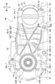
- 1 is a left side view showing a reduction gear transmission according to a first embodiment of the present invention.
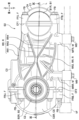
- FIG. 1 is a right side view showing a reduction gear transmission according to a first embodiment of the present invention.
- FIG. 2 is a bottom view showing the reduction gear transmission according to the first embodiment of the present invention.
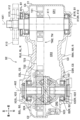
- FIG. 4 is a cross-sectional view taken along line V-V in FIG.
- FIG. 6 is a cross-sectional view taken along line VI-VI in FIG.
- FIG. 7 is a cross-sectional view taken along line VII-VII in FIG. 3 .
- FIG. 4 is a right side view showing a reduction gear transmission according to second and third embodiments of the present invention.
- FIG. 9 is a cross-sectional view taken along line IX-IX of FIG. 8 , showing a reduction gear transmission according to a second embodiment of the present invention.
- 9 is a cross-sectional view taken along line IX-IX of FIG. 8 , showing a reduction gear transmission according to a third embodiment of the present invention.
- FIG. 11 is a right side view showing a reduction gear transmission according to a fourth embodiment of the present invention.
- FIG. 13 is a right side view showing a reduction gear transmission according to a fifth embodiment of the present invention.
- FIG. 13 is a cross-sectional view taken along line XIII-XIII in FIG. 12 .
- a reduction gear transmission S1 according to a first embodiment of the present invention will be described in detail with reference to FIGS. In the description, the same elements are given the same reference numerals and duplicated descriptions are omitted.
- the reduction gear S1 of this embodiment is mounted on a four-wheeled saddle-ride vehicle (not shown) known as a buggy.
- the reduction gear S1 reduces the rotational speed of the rotational force of the prime mover (not shown) output through a transmission (not shown), increasing the rotational torque and transmitting it to the axle (not shown) of the rear wheel (not shown).
- the reduction gear S1 includes a housing CA, an input shaft member X11, a differential mechanism X20 (output shaft member), and a bevel gear mechanism TM1 (transmission means TM) (see FIG. 5).
- the housing CA has a hollow shell shape in which an input side housing chamber CR1, an output side housing chamber CR2, and a transmission section housing chamber CR3 are formed.
- the input side accommodating chamber CR1 is disposed in front of the housing CA, and the output side accommodating chamber CR2 is disposed in the rear of the housing CA.
- a transmission portion accommodating chamber CR3 is formed to connect the input side accommodating chamber CR1 and the output side accommodating chamber CR2.
- the housing CA is divided into three members: a housing front portion C1, a housing rear portion C2, and a housing center portion C3 (see FIGS. 1 and 2).
- the housing front portion C1 and the housing center portion C3 are divided by a plane (input side dividing surface CF1) along the vertical direction including an input axis AX1 described later.
- the housing center portion C3 and the housing rear portion C2 are divided by a plane (output side dividing plane CF2) along the vertical direction including an output axis AX2 described later.
- the housing CA is divided into three by an input side dividing surface CF1 including the input shaft AX1 and an output side dividing surface CF2 including the output shaft AX2.
- the front portion C1 and the central portion C3 of the housing, and the central portion C3 and the rear portion C2 of the housing are fastened to each other by fastening bolts FB screwed into fastening portions F.
- the housing CA is provided with a mount M and is attached to the vehicle frame VF by mount bolts MB (see FIGS. 3 and 4).
- the fastening section F is composed of an input side upper fastening section FFU, an input side lower fastening section FFB, an output side upper fastening section FRU, and an output side lower fastening section FRB (see Figures 2 and 3).
- the input side upper fastening part FFU has a through hole formed in the upper part of the housing front part C1 and a female threaded part formed in the upper part of the housing center part C3, across the input side split surface CF1, and the fastening bolt FB is inserted through the through hole and screwed into the female threaded part.
- the input side lower fastening portion FFB has a through hole formed in the lower part of the housing front portion C1 and a female threaded portion formed in the lower part of the housing center portion C3, across the input side split surface CF1, and the fastening bolt FB is inserted through the through hole and screwed into the female threaded portion.
- the output side upper fastening part FRU has a through hole formed in the upper part of the rear part C2 of the housing and a female threaded part formed in the upper part of the central part C3 of the housing, across the output side split surface CF2, and the fastening bolt FB is inserted through the through hole and screwed into the female threaded part.
- the output side lower fastening part FRB has a through hole formed in the lower part of the rear part C2 of the housing and a female threaded part formed in the lower part of the central part C3 of the housing, across the output side split surface CF2, and the fastening bolt FB is inserted through the through hole and screwed into the female threaded part.
- Mount M is composed of an input side left mount MFL, an input side right mount MFR, an input side left mount MRL, and an output side right mount MRR (see Figures 3 and 4).
- the input side housing chamber CR1 houses an input shaft member X11
- the output side housing chamber CR2 houses a differential mechanism X20 (output shaft member) (see FIG. 5).
- the transmission portion accommodation chamber CR3 accommodates a transmission means TM that links the input shaft member X11 and the differential mechanism X20.
- the housing CA is provided with reinforcing ribs R on the outer surfaces of a left side wall CSL and a right side wall CSR facing in the vehicle width direction. In other words, the housing CA has a plurality of reinforcing ribs R standing on its outer circumferential surface.
- the input shaft member X11 is rotatably supported about an input shaft AX1 that is set along the vehicle width direction.
- the input shaft member X11 has a left end portion that penetrates through a left side wall CSL of the housing CA and is supported by the housing CA via a pair of input bearings X12 in an exposed state.
- the input bearing X12 is made up of a right input bearing X12R and a left input bearing X12L.
- the right input bearing X12R is fitted into a right input boss B1R (input boss B1) formed on the inner surface of the right side wall CSR of the input side accommodation chamber CR1, and supports the right end of the input shaft member X11.
- the left input bearing X12L is fitted into a left input boss B1L (input boss B1) formed on the inner surface of the left side wall CSL of the input side accommodation chamber CR1, and supports the left end side of the input shaft member X11.
- a sprocket X13 is disposed on the left end of the input shaft member X11 that is exposed to the outside of the housing CA, and the power output from the transmission is input via a stretched chain (not shown).
- the differential mechanism X20 (output shaft member) distributes and transmits driving force to the inner and outer axles while creating a rotational difference corresponding to the inner wheel difference that occurs between the inner and outer axles when the vehicle turns.
- the differential mechanism X20 is composed of a differential case X21, a pair of pinion gears X23, and left and right side gears X24, and the left and right side gears X24 are spline-connected to the left and right axles.
- the rotational force input to the differential case X21 is transmitted to the left and right axles (not shown) via the pinion gears X23 and side gears X24.
- the differential case X21 is supported by the housing CA via a pair of output bearings X22, with the output shaft AX2 set in parallel with the input shaft AX1 along the vehicle width direction as the center of rotation.
- the output bearing X22 is made up of a right output bearing X22R and a left output bearing X22L.
- the right output bearing X22R is fitted into a right output boss B2R (output boss B2) formed on the inner surface of the right side wall CSR of the output side accommodation chamber CR2, and supports the right end of the differential case X21.
- the left output bearing X22L is fitted into a left output boss B2L (output boss B2) formed on the inner surface of the left side wall CSL of the output side accommodation chamber CR2, and supports the left end of the differential case X21.
- the side gear X24 is held in a floating state within the differential case X21 so as to be rotatable relative to the output shaft AX2.
- the left and right axles (not shown) rotate about the output shaft AX2.
- the differential mechanism X20 is set so that the axle of the rear wheels and the rotation axis of the differential case X21 coincide with the output shaft AX2.
- the transmission means TM is composed of a bevel gear mechanism TM1 using bevel gears, and transmits the rotational force input to the input shaft member X11 via the first transmission shaft member T10 to a differential case X21 that constitutes the differential mechanism X20 (output shaft member).
- the bevel gear mechanism TM1 is linked so that, when transmitting rotational force, the differential case X21 rotates in the same direction as the input shaft member X11.
- the bevel gear mechanism TM1 includes a first transmission shaft member T10, an input gear T11, an input side transmission gear T13, an output side transmission gear T14, and an output gear T12.
- the first transmission shaft member T10 is disposed between the input shaft AX1 and the output shaft AX2, and is supported rotatably about a transmission shaft AX3 (first transmission shaft).
- the transmission shaft AX3 is set to be perpendicular to the input shaft AX1.
- the input gear T11 is a gear formed on the right end side of the input shaft member X11.
- the input side transmission gear T13 is a gear formed on the front end side of the first transmission shaft member T10.
- the input gear T11 and the input side transmission gear T13 are configured as bevel gears that can mesh with each other.
- the output side transmission gear T14 is a gear formed on the rear end side of the first transmission shaft member T10.
- the output gear T12 is a ring gear formed on the outer periphery of the differential case X21.
- the output side transmission gear T14 and the output gear T12 are configured as hypoid gears that can mesh with each other.
- the front end side of the first transmission shaft member T10 is journaled to the front end portion of the transmission portion accommodation chamber CR3 via an input side transmission bearing T15.
- the rear end side of the first transmission shaft member T10 is journaled to the rear end portion of the transmission portion accommodation chamber CR3 via an output side transmission bearing T16.
- the input side transmission bearing T15 is fitted into an input side transmission boss B3 formed on the inner surface of the front end of the transmission portion accommodating chamber CR3, and supports the front end of the first transmission shaft member T10.
- the output side transmission bearing T16 is fitted into an output side transmission boss B4 formed on the inner surface of the rear end of the transmission portion accommodating chamber CR3, and supports the rear end of the first transmission shaft member T10.
- the reinforcing rib R is made up of a left reinforcing rib RL and a right reinforcing rib RR (see FIGS. 1 to 3).
- the left reinforcing rib RL is provided on the outer circumferential surface of the left side wall CSL of the housing CA along the input axis AX1 (see FIGS. 1 and 2).
- the left reinforcing rib RL is composed of an upper left convex upper rib RL1, an upper left convex middle rib RL2, an upper left convex lower rib RL3, a lower left convex rib RL4, a left front rising rib RL5, and a left front falling rib RL6.
- the right reinforcing rib RR is provided on the outer circumferential surface of the right side wall CSR of the housing CA along the input axis AX1.
- the right reinforcing rib RR is composed of an upper right convex rib RR1, a lower right convex rib RR2, a front right upward rib RR3, and a front right downward rib RR4.
- the upper left convex upper rib RL1 (first rib, fifth rib) originates from the vertical upper part of the left input boss B1L (input boss B1) on the outer peripheral surface of the left side wall CSL, and is connected to the starting point via the input side upper fastening part FFU.
- the upper left convex upper rib RL1 terminates at the vertical upper portion of the left output boss B2L (output boss B2) on the outer circumferential surface of the left side wall CSL, and is connected to the end point via the output side upper fastening part FRU.
- a portion of the left input boss B1L located above the input shaft AX1 is set as the starting point, and a portion of the left output boss B2L located above the input shaft AX1 is set as the end point.
- the left upper convex upper rib RL1 is provided on the left outer peripheral surface of the housing CA along the input axis AX1, with the intermediate portion between the starting point and the end point curved in a vertically upward convex arc shape.
- the upper left convex middle rib RL2 (first rib) originates from the vertical upper part of the input side transmission boss B3 on the outer circumferential surface of the left side wall CSL.
- the upper left convex middle rib RL2 terminates at the left output boss B2L (output boss B2) on the outer circumferential surface of the left side wall CSL.
- the upper left convex middle rib RL2 is provided on the left outer peripheral surface of the housing CA along the input axis AX1, with the intermediate portion between the starting point and the end point curved in a vertically upward convex arc.
- the upper left convex lower rib RL3 (first rib) originates from the input side transmission boss B3 on the outer circumferential surface of the left side wall CSL. Additionally, the upper left convex middle rib RL2 terminates at the output side transmission boss B4 on the outer circumferential surface of the left side wall CSL.
- the upper left convex lower rib RL3 is provided on the left outer peripheral surface of the housing CA along the input axis AX1 with the intermediate portion between the starting point and the end point curved in a vertically upward convex arc shape.
- the upper left convex upper rib RL1, the upper left convex middle rib RL2, and the upper left convex lower rib RL3 form an arc shape whose middle portion is spaced upward from the imaginary straight line L connecting the input shaft AX1 and the output shaft AX2.
- the lower left convex rib RL4 (second rib, sixth rib) originates from the vertical lower part of the left input boss B1L (input boss B1) on the outer peripheral surface of the left side wall CSL, and is connected to the origin via the input side lower fastening part FFB and the input side left mount MFL.
- the left lower convex rib RL4 is connected to the outer circumferential surface of the left side wall CSL at a vertically lower portion of the left output boss B2L (output boss B2).
- a portion of the left input boss B1L located below the input shaft AX1 is set as the starting point
- a portion of the left output boss B2L located below the output shaft AX2 is set as the end point.
- the left lower convex rib RL4 is provided on the left outer peripheral surface of the housing CA along the input axis AX1 with an intermediate portion between the starting point and the end point curved in a vertically downward convex arc shape.
- the left lower convex rib RL4 forms an arc shape with a middle portion spaced downward from the imaginary straight line L connecting the input shaft AX1 and the output shaft AX2.
- the left front rising rib RL5 (third rib, seventh rib) originates from the vertical upper part of the left input boss B1L (input boss B1) on the outer peripheral surface of the left side wall CSL, and is connected to the origin via the input side upper fastening part FFU.
- the left front upward rib RL5 is connected to the outer circumferential surface of the left side wall CSL at a vertically lower portion of the left output boss B2L (output boss B2).
- a portion of the left input boss B1L located above the input shaft AX1 is set as the starting point
- a portion of the left output boss B2L located below the output shaft AX2 is set as the end point.
- the left front upward rib RL5 connects these starting points and ending points in a straight line and is provided on the left outer peripheral surface of the housing CA along the input axis AX1.
- the left front downward rib RL6 (fourth rib, eighth rib) originates from the vertical lower part of the left input boss B1L (input boss B1) on the outer peripheral surface of the left side wall CSL, and is connected to the origin via the input side lower fastening part FFB.
- the left front downward rib RL6 terminates at the vertical upper portion of the left output boss B2L (output boss B2) on the outer circumferential surface of the left side wall CSL, and is connected to the end point via the output-side upper fastening part FRU.
- the left front downward rib RL6 connects these starting points and ending points in a straight line and is provided on the left outer peripheral surface of the housing CA along the input axis AX1.
- the left front upward rib RL5 and the left front downward rib RL6 intersect at the center of the left side wall of the housing CA.
- the upper right convex rib RR1 (first rib, fifth rib) originates from the vertical upper part of the right input boss B1R (input boss B1) on the outer peripheral surface of the right side wall CSR, and is connected to the origin via the input side upper fastening part FFU (see Figure 3).
- the upper right convex rib RR1 terminates at the vertical upper portion of the right output boss B2R (output boss B2) on the outer peripheral surface of the right side wall CSR, and is connected to the end point via the output-side upper fastening part FRU.
- the upper right convex rib RR1 is provided on the right outer peripheral surface of the housing CA along the input axis AX1 with the intermediate portion between the starting point and the end point curved in a vertically upward convex arc.
- the upper right convex rib RR1 forms an arc shape with a middle portion spaced upward from the imaginary straight line L connecting the input shaft AX1 and the output shaft AX2.
- the lower right convex rib RR2 (second rib, sixth rib) originates from the vertical lower part of the right input boss B1R (input boss B1) on the outer peripheral surface of the right side wall CSR, and is connected to the origin via the input side upper fastening part FFU and the input side right mount MFR.
- the right lower convex rib RR2 is connected to the outer circumferential surface of the right side wall CSR at a vertically lower portion of the right output boss B2R (output boss B2).
- a portion of the right input boss B1R located below the input shaft AX1 is set as the starting point
- a portion of the right output boss B2R located below the input shaft AX1 is set as the end point.
- the right lower convex rib RR2 is provided on the right outer peripheral surface of the housing CA along the input axis AX1 with an intermediate portion between the starting point and the end point curved in a vertically downward convex arc shape.
- the right lower convex rib RR2 forms an arc shape with a middle portion spaced downward from the imaginary straight line L connecting the input shaft AX1 and the output shaft AX2.
- the right front rising rib RR3 (third rib, seventh rib) originates from the vertical upper part of the right input boss B1R (input boss B1) on the outer peripheral surface of the right side wall CSR, and is connected to the origin via the input side upper fastening part FFU.
- the right front upward rib RR3 is connected to the outer peripheral surface of the right side wall CSR at a vertically lower portion of the right output boss B2R (output boss B2).
- a portion of the right input boss B1R located above the input shaft AX1 is set as the starting point
- a portion of the right output boss B2R located below the output shaft AX2 is set as the end point.
- the right front upward rib RR3 connects these starting points and ending points in a straight line and is erected on the right outer peripheral surface of the housing CA along the input axis AX1.
- the right front downward rib RR4 (fourth rib, eighth rib) originates from the vertical lower part of the right input boss B1R (input boss B1) on the outer peripheral surface of the right side wall CSR, and is connected to the origin via the input side upper fastening part FFU.
- the right front downward rib RR4 terminates at the vertical upper portion of the right output boss B2R (output boss B2) on the outer peripheral surface of the right side wall CSR, and is connected to the end point via the output-side lower fastening part FRB.
- a portion of the right input boss B1R located below the input shaft AX1 is set as the starting point
- a portion of the right output boss B2R located above the output shaft AX2 is set as the end point.
- the right front downward rib RR4 connects these starting points and ending points in a straight line and is provided on the right outer peripheral surface of the housing CA along the input axis AX1.
- the right front upward rib RR3 and the right front downward rib RR4 intersect at the center of the right side wall of the housing CA.
- the height of each of these reinforcing ribs R is set to be highest near the starting point and near the end point, and lowest near the middle part between the starting point and the end point (see Figures 4, 6, and 7).
- a first rib, a fifth rib (upper-left convex upper rib RL1, upper-right convex rib RR1), a second rib, and a sixth rib (lower-left convex rib RL4, lower-right convex rib RR2) are provided on the left side wall CSL and right side wall CSR of the housing CA.
- first rib By providing a first rib, a fifth rib, a second rib, and a sixth rib to withstand such bending loads, it is possible to avoid increasing the size of the housing CA of the reduction gear S1, and to increase the strength and durability while maintaining a lightweight structure. Furthermore, by preventing the entire device from becoming larger, it is possible to increase the degree of freedom in the layout of peripheral components when the reduction gear transmission S1 is installed in a vehicle.
- first rib, the fifth rib, the second rib, and the sixth rib form an arc shape
- a compressive load acts on the first rib, the fifth rib, the second rib, and the sixth rib in the fore-and-aft direction of the vehicle.
- This provides a sufficient suppression effect against bending the housing CA.
- by suppressing bending deformation of the casing CA it is possible to maintain a proper fit of the gears constituting the transmission means TM. This ensures the strength and durability of the transmission means TM and prevents the generation of abnormal noise due to poor meshing.
- an input side dividing surface CF1 that divides the housing front portion C1 and the housing center portion C3 is a flat surface that is aligned in the vertical direction and includes the input axis AX1.
- the output-side dividing surface CF2 that divides the housing center portion C3 and the housing rear portion C2 is a flat surface that is aligned in the vertical direction and includes the input axis AX1.
- each reinforcing rib R is connected at its start point and end point via a fastening portion F and a mount M. Since the fastening portion F and the mount M are formed to be more rigid than other parts of the housing CA, the rigidity of the housing CA can be further increased by connecting each reinforcing rib R to its starting point and end point via the fastening portion F and the mount M.
- a reduction gear transmission S2 according to a second embodiment of the present invention will be described with reference to FIGS.
- the same elements as those in the first embodiment described above are denoted by the same reference numerals, and duplicated descriptions will be omitted.
- the configuration of the transmission means is different from that of the transmission means TM of the first embodiment.
- the start point and end point of the reinforcing rib R are changed. Except for the transmission means and the reinforcing rib R, the other configurations are the same as those of the first embodiment.
- a chain drive TM2 is adopted as the transmission means.
- the chain drive TM2 is composed of an input sprocket T21, an output sprocket T22, and a chain T23.
- the input sprocket T21 is provided on the input shaft member X11 and rotates together with the input shaft member X11 about the input shaft AX1.
- the output sprocket T22 is provided on the differential case X21 (output shaft member) and rotates together with the differential case X21 about the output shaft AX2.
- the chain T23 is stretched across the input sprocket T21 and the output sprocket T22, and transmits the rotational force of the input sprocket T21 to the output sprocket T22.
- the housing CA does not have configurations equivalent to the input side transmission boss B3 and the output side transmission boss B4. Therefore, the reinforcing rib R disposed above the imaginary straight line L has its starting point set at the vertical upper part of the input boss B1 and its end point set at the vertical upper part of the output boss B2.
- the fifth rib (upper left convex upper rib RL1, upper right convex rib RR1) is erected on the outer circumferential surface of the housing CA along the input axis AX1, with the intermediate portion between its starting point and end point forming an arc shape that moves upward from the imaginary straight line L connecting the input shaft AX1 and the output shaft AX2.
- the reinforcing rib R disposed below the imaginary straight line L has a starting point set at the vertical lower part of the input boss B1 and an end point set at the vertical lower part of the output boss B2.
- the sixth rib (left lower convex rib RL4, right lower convex rib RR2) is erected on the outer circumferential surface of the housing CA along the input axis AX1, with the intermediate portion between the starting point and the end point forming an arc shape that moves downward from the imaginary straight line L connecting the input shaft AX1 and the output shaft AX2.
- a chain drive is adopted as the transmission means, but the present invention is not limited to this.
- a belt drive using a toothed belt (not shown) can be adopted, and the same effects as those of this embodiment can be obtained.
- a reduction gear transmission S3 according to a third embodiment of the present invention will be described with reference to FIGS.
- the same elements as those in the first embodiment described above are denoted by the same reference numerals, and duplicated descriptions will be omitted.
- the configuration of the transmission means is different from that of the transmission means TM of the first embodiment.
- the reinforcing rib R is changed to have the same configuration as that of the second embodiment. Except for the transmission means and the reinforcing rib R, the other configurations are the same as those of the first embodiment.
- the spur gear mechanism TM3 includes a transmission shaft member T31 (second transmission shaft member), an input gear T32, an input side transmission gear T34, an output side transmission gear T35, and an output gear T33.
- the transmission shaft member T31 is disposed between the input shaft AX1 and the output shaft AX2, and is rotatably supported via a transmission bearing T36 around a transmission shaft AX4 (second transmission shaft).
- the transmission shaft AX4 is set to be parallel to the input shaft AX1.
- the input gear T32 is a spur gear formed on the input shaft member X11.
- the input side transmission gear T34 is formed on the transmission shaft member T31, is capable of meshing with the input gear T11, and is configured as a spur gear having a greater number of teeth than the input gear T11.
- the output side transmission gear T35 is a spur gear formed on the transmission shaft member T31.
- the output gear T12 is formed on the outer periphery of the differential case X21, is capable of meshing with the output side transmission gear T35, and is configured as a spur gear having fewer teeth than the input side transmission gear T34.
- the housing CA does not have configurations equivalent to the input side transmission boss B3 and the output side transmission boss B4. Therefore, the reinforcing rib R is modified to have a configuration similar to that of the second embodiment.
- a reduction gear transmission S4 according to a fourth embodiment of the present invention will be described with reference to FIG.
- the same elements as those in the first embodiment described above are denoted by the same reference numerals, and duplicated descriptions will be omitted.
- the configuration of the casing CA is different from that of the first embodiment. Except for the housing CA, the other configurations are similar to those of the first embodiment.
- the configuration of the input-side dividing surface CF1 that divides the housing front portion C1 and the housing center portion C3 is different from that of the first embodiment.
- the input side dividing surface CF1 of this embodiment is configured as a front-down surface including the input shaft AX1.
- the input-side cutting surface CF1 may be formed of a rearwardly sloping surface including the input shaft AX1
- the output-side cutting surface CF2 may be formed of a frontwardly sloping or rearwardly sloping surface including the output shaft AX2.
- a reduction gear transmission S5 according to a fifth embodiment of the present invention will be described with reference to FIGS.
- the same elements as those in the first embodiment described above are denoted by the same reference numerals, and duplicated descriptions will be omitted.
- the configuration of the mount M is different from that of the first embodiment. Except for the mount M, the other configurations are the same as those of the first embodiment.
- the mount M is set horizontally, and the reduction gear S5 is fixed to the vehicle body frame VF via a pair of mount bolts MB. That is, one of the mount bolts MB passes through the input side left mount MFL, the input side right mount MFR, and the vehicle body frame VF, and is screwed into the nut MN. The other mount bolt MB passes through the input side left mount MRL, the output side right mount MRR, and the vehicle body frame VF, and is screwed into a nut MN.
- This configuration makes it possible to mount the reduction gear S5 at a lower position relative to the vehicle body frame VF, which in turn keeps the center of gravity of the vehicle lower, improving driving stability. In addition, when going over a step, the step will no longer interfere with the bolt, further improving reliability.
Landscapes
- Engineering & Computer Science (AREA)
- General Engineering & Computer Science (AREA)
- Mechanical Engineering (AREA)
- General Details Of Gearings (AREA)
Priority Applications (3)
| Application Number | Priority Date | Filing Date | Title |
|---|---|---|---|
| JP2025558925A JPWO2025109646A1 (https=) | 2023-11-20 | 2023-11-20 | |
| PCT/JP2023/041599 WO2025109646A1 (ja) | 2023-11-20 | 2023-11-20 | 減速装置 |
| CN202380102772.3A CN121925526A (zh) | 2023-11-20 | 2023-11-20 | 减速装置 |
Applications Claiming Priority (1)
| Application Number | Priority Date | Filing Date | Title |
|---|---|---|---|
| PCT/JP2023/041599 WO2025109646A1 (ja) | 2023-11-20 | 2023-11-20 | 減速装置 |
Publications (1)
| Publication Number | Publication Date |
|---|---|
| WO2025109646A1 true WO2025109646A1 (ja) | 2025-05-30 |
Family
ID=95826318
Family Applications (1)
| Application Number | Title | Priority Date | Filing Date |
|---|---|---|---|
| PCT/JP2023/041599 Pending WO2025109646A1 (ja) | 2023-11-20 | 2023-11-20 | 減速装置 |
Country Status (3)
| Country | Link |
|---|---|
| JP (1) | JPWO2025109646A1 (https=) |
| CN (1) | CN121925526A (https=) |
| WO (1) | WO2025109646A1 (https=) |
Citations (4)
| Publication number | Priority date | Publication date | Assignee | Title |
|---|---|---|---|---|
| JPS62145790U (https=) * | 1986-07-03 | 1987-09-14 | ||
| JPH0825990A (ja) * | 1994-07-19 | 1996-01-30 | Mazda Motor Corp | 4輪駆動車の動力伝達装置 |
| JP2010221885A (ja) * | 2009-03-24 | 2010-10-07 | Honda Motor Co Ltd | 自動二輪車 |
| JP2023028863A (ja) * | 2021-08-20 | 2023-03-03 | 日本電産株式会社 | 駆動装置 |
-
2023
- 2023-11-20 JP JP2025558925A patent/JPWO2025109646A1/ja active Pending
- 2023-11-20 WO PCT/JP2023/041599 patent/WO2025109646A1/ja active Pending
- 2023-11-20 CN CN202380102772.3A patent/CN121925526A/zh active Pending
Patent Citations (4)
| Publication number | Priority date | Publication date | Assignee | Title |
|---|---|---|---|---|
| JPS62145790U (https=) * | 1986-07-03 | 1987-09-14 | ||
| JPH0825990A (ja) * | 1994-07-19 | 1996-01-30 | Mazda Motor Corp | 4輪駆動車の動力伝達装置 |
| JP2010221885A (ja) * | 2009-03-24 | 2010-10-07 | Honda Motor Co Ltd | 自動二輪車 |
| JP2023028863A (ja) * | 2021-08-20 | 2023-03-03 | 日本電産株式会社 | 駆動装置 |
Also Published As
| Publication number | Publication date |
|---|---|
| JPWO2025109646A1 (https=) | 2025-05-30 |
| CN121925526A (zh) | 2026-04-24 |
Similar Documents
| Publication | Publication Date | Title |
|---|---|---|
| US9586457B2 (en) | Active rotary stabilizer and stabilizer bar link assembly for vehicle | |
| US7913793B2 (en) | Shaft-driven motorcycle with pivotally mounted swing arm and related support structure | |
| JP6518722B2 (ja) | 動力装置の支持構造 | |
| JP7307128B2 (ja) | 自転車用ドライブユニットおよび自転車 | |
| EP1101645B1 (en) | Low floor drive unit assembly for an electrically driven vehicle | |
| JP6865699B2 (ja) | 電気車両および電気車両用の駆動システム | |
| CN110121441B (zh) | 马达驱动装置 | |
| JP6706517B2 (ja) | インホイールモータ駆動装置とサスペンション装置の連結構造 | |
| JP6098276B2 (ja) | シートスライド装置 | |
| WO2018061967A1 (ja) | インホイールモータ駆動装置 | |
| WO2025109646A1 (ja) | 減速装置 | |
| JP6823728B2 (ja) | 車両 | |
| JP2024074920A (ja) | リーン車両 | |
| WO2025109647A1 (ja) | 減速装置 | |
| JP2017106596A (ja) | インホイールモータ駆動装置 | |
| US20230192232A1 (en) | Vehicle | |
| JP5665513B2 (ja) | 作業車両 | |
| CN110758085B (zh) | 一种新能源汽车动力分流用行星齿轮动力传动结构 | |
| WO2025142148A1 (ja) | 動力変換装置 | |
| JP6932875B2 (ja) | モータ駆動装置 | |
| JP6757630B2 (ja) | インホイールモータ駆動装置 | |
| JP7852471B2 (ja) | パワーユニット | |
| CN216045287U (zh) | 差速器齿轮机构及汽车 | |
| JP2025171650A (ja) | 車両 | |
| JP2013002563A (ja) | デファレンシャル装置及びリング・ギヤ |
Legal Events
| Date | Code | Title | Description |
|---|---|---|---|
| 121 | Ep: the epo has been informed by wipo that ep was designated in this application |
Ref document number: 23959391 Country of ref document: EP Kind code of ref document: A1 |
|
| ENP | Entry into the national phase |
Ref document number: 2025558925 Country of ref document: JP Kind code of ref document: A |