Attorney Docket No: 3192-111-01 PCT DIALYZERS UTILIZING SMALL DIAMETER HOLLOW FIBER MEMBRANES BACKGROUND OF THE INVENTION [0001] This application claims the benefit under 35 U.S.C. §119(e) of prior U.S. Provisional Patent Application No.63/547,602, filed November 7, 2023, which is incorporated in its entirety by reference herein. [0002] The present invention relates to dialyzers as well as methods for using the same (e.g., for dialysis). [0003] Hollow fiber membranes are widely used in the filtration of liquids. In particular, hollow fiber membranes are used in medical applications for purifying blood during dialysis treatments of patients with kidney disease. Hollow fiber membranes are formed into bundles within filter modules and used for the extracorporeal treatment of blood. Filter modules of this type for hemopurification, so-called hemodialyzers, are produced on a mass scale. [0004] Conventional hollow fiber membranes for use in hemopurification generally have an inner diameter (ID) between 180 microns (i.e., micrometers or µm) and 250 microns and wall thicknesses between 30 microns and 50 microns to maintain structural integrity of the membrane and allow intralumenal blood passage without undesired shearing, fouling, and associated hemocompatability issues. [0005] WO2018/167280 describes a hollow fiber membrane dialyzer having undulating fibers with a wall thickness of 20 µm to 30 µm, ID of 160 um to 230 um, and a reduced fiber wavelength of 1 mm to 4 mm to improve thermal stability during manufacturing. [0006] WO2012/51595 describes cytopheretic cartridges incorporating hollow fiber membrane bundles for therapeutic sequestration of activated leukocytes from blood. The fibers have a theoretical ID of 50 µm to 240 µm with a wall thickness of about 40 µm. Blood passes through filter modules preferably on the outside of the hollow fiber membranes at a low flow rate to reduce shear forces and promote sequestration onto the membrane.
Attorney Docket No: 3192-111-01 PCT [0007] WO2008/046779 describes a hollow fiber membrane for use in hemodialysis having a theoretical ID of 50 µm to 2000 µm and wall thickness of 10 µm to 200 µm. The membrane has four to five distinct layers, including a selective layer with the lowest pore size on its outer surface, and a supportive layer in the middle of the membrane wall that is denser and has a lower pore size than the two adjacent layers. [0008] It would be beneficial to develop a hollow fiber membrane with a thin wall and low ID that maintains the structural integrity and performance of conventional membranes, without increasing production complexity. The advantages of such a design are further described herein. SUMMARY OF THE PRESENT INVENTION [0009] A feature of the present invention is to provide a hollow fiber membrane that has a narrow inner diameter (ID) for the lumenal compartment. [0010] A further feature of the present invention is to provide a hollow fiber membrane that has a narrow inner diameter for the lumenal compartment in combination with a narrow wall thickness. [0011] An additional feature of the present invention is to provide hollow fibers which can at least partially remove larger uremic solutes from a patient's fluids, such as blood. [0012] A further feature of the present invention is to provide a hollow fiber membrane with a high surface area relative to the weight of the fiber. [0013] Additional features and advantages of the present invention will be set forth in part in the description that follows, and in part will be apparent from the description, or may be learned by practice of the present invention. The objectives and other advantages of the present invention will be realized and attained by means of the elements and combinations particularly pointed out in the description and appended claims. [0014] To achieve these and other advantages, and in accordance with the purposes of the present invention, as embodied and broadly described herein, the present invention relates to a
Attorney Docket No: 3192-111-01 PCT porous hollow fiber membrane. The porous hollow fiber membrane includes a lumenal compartment, an inner surface adjacent to the lumenal compartment, and an outer surface. The porous hollow fiber membrane has a wall that is defined from the inner surface to the outer surface and has a wall thickness of from about 10 µm (micrometers) to about 30 µm. The lumenal compartment has an inner diameter (ID) of from about 90 µm to about 160 µm. An active surface or selective surface is further present at the inner surface of the porous hollow fiber membrane and a non-active region or support region is further present and adjacent to the active surface. The membrane wall may have a generally asymmetric architecture when its porous structure is viewed microscopically or otherwise analyzed for density. Optionally, the porous hollow fiber membrane has a porosity such that the porosity of the membrane generally increases from the active surface (inner surface) across the wall thickness and to the outer surface. [0015] The present invention also relates to porous hollow fiber membranes where the porous hollow fiber membrane includes a lumenal compartment, an inner surface adjacent to the lumenal compartment, and an outer surface. The porous hollow fiber membrane has a wall that is defined from the inner surface to the outer surface and has a wall thickness of from about 10 µm (micrometers) to about 30 µm. The lumenal compartment has an inner diameter (ID) of from about 90 µm to about 160 µm. An active surface or selective surface is further present at the inner surface, or the outer surface, or both the inner surface and the outer surface of the porous hollow fiber membrane, and a non-active region or support region is further present and adjacent to the active surface(s). The porous hollow fiber membrane has a mass density through the wall thickness, such that the mass density from the inner surface to the outer surface is a gradient of increasing or decreasing mass density. [0016] The present invention also relates to a porous hollow fiber membrane having a lumenal compartment and prepared from a solution comprising at least one membrane forming polymer and at least one solvent. The solution can include at least one hydrophobic polymer such as
Attorney Docket No: 3192-111-01 PCT polysulfone (PSF), polyethersulfone (PES), polyarylsulfone (PAS), and/or polyarylethersulfone (PAES), at least one hydrophilic polymer, and at least one solvent. The solution can alternatively include one or more polymethyl methacrylate polymers (PMMA), cellulose triacetate (CTA), polyvinylidene fluoride (PVDF), and/or polyacrylonitrile (PAN), or any copolymer thereof, and at least one solvent, and may exclude a hydrophilic polymer. The porous hollow fiber membrane has a wall thickness of from about 10 µm to about 30 µm. The lumenal compartment has an inner diameter (ID) of from about 90 µm to about 160 µm. The porous hollow fiber membrane has a mass density throughout the wall thickness, such that the mass density from the inner surface to the outer surface is a gradient of increasing or decreasing mass density. [0017] The present invention further relates to a porous hollow fiber membrane for use in extracorporeal blood therapy. The porous hollow fiber membrane includes a lumenal compartment, an inner surface adjacent to the lumenal compartment, and an outer surface. The porous hollow fiber membrane has a wall that is defined from the inner surface to the outer surface and has a wall thickness of from about 20 µm to about 26 µm. The lumenal compartment has an inner diameter (ID) of from about 110 µm to about 140 µm. An active surface is further present at the inner surface of the porous hollow fiber membrane and a non-active region or support region is further present and adjacent to the active surface. Optionally, the porous hollow fiber membrane has porosity such that the porosity of the membrane increases from the active surface across the wall thickness and to the outer surface. [0018] The present invention additionally relates to methods of making the porous hollow fiber membranes of the present invention. [0019] The present invention further relates to a bundle of porous hollow fiber membranes and a dialyzer comprising such a bundle of fibers, the dialyzer having an outer housing, an inner compartment bounded by the inner wall of the housing to contain the bundle, one or more blood
Attorney Docket No: 3192-111-01 PCT ports to enter and exit the housing, and one or more ports for dialysis fluid to enter and exit the housing. [0020] The present invention further relates to a process for dialysis, blood oxygenation, or blood separation comprising contacting blood with the porous membrane of the present invention. For purposes herein, the term “dialysis” can refer to any of the primary and secondary types of dialysis, which can include, e.g., hemodialysis, hemofiltration and/or hemodiafiltration. [0021] It is to be understood that both the foregoing general description and the following detailed description are exemplary and explanatory only and are intended to provide a further explanation of the present invention, as claimed. [0022] The accompanying drawings, which are incorporated in and constitute a part of this application, illustrates various features of the present invention and, together with the description, serve to explain the principles of the present invention. BRIEF DESCRIPTION OF DRAWINGS [0023] FIG.1 is a flow chart illustrating exemplary method steps that can be used to form the hollow fiber membranes of the present invention. [0024] FIG. 2 is a further flow chart illustrating other exemplary method steps that can be used to form the hollow fiber membranes of the present invention. [0025] FIG.3 is a graph that plots sodium overall mass transfer coefficient versus bore fluid water content data related to a hollow fiber membrane of the present invention. [0026] FIG.4A is a graph that plots Sodium (Na) Clearance versus Raw Aqueous KUF for three hollow fiber membranes of the present invention. [0027] FIG.4B is a graph that plots Sodium (Na) Clearance versus Membrane Area for three hollow fiber membranes of the present invention and conventional fiber membrane (F160Re).
Attorney Docket No: 3192-111-01 PCT [0028] FIG.5A is a graph that plots Creatinine Clearance versus Raw Aqueous KUF for three hollow fiber membranes of the present invention. [0029] FIG. 5B is a graph that plots Creatinine Clearance versus Membrane Area for three hollow fiber membranes of the present invention and conventional fiber membrane (F160NRe). [0030] FIG. 6A is a graph that plots B12 Clearance versus Raw Aqueous KUF for three hollow fiber membranes of the present invention. [0031] FIG.6B is a graph that plots B12 Clearance versus Membrane Area for three hollow fiber membranes of the present invention and conventional fiber membrane (F160NRe). [0032] FIG. 7 is a table that sets forth hollow fiber membrane samples with Raw Aqueous KUF, Lab. Aqueous KUF, B2M Clearance, and Albumin Sieving coefficient data. [0033] FIG.8A is graph that plots Albumin Sieving coefficient numbers versus Raw Aqueous KUF for two hollow fiber membranes of the present invention and a conventional fiber membrane (F160NRe). [0034] FIG.8B is a graph that plots Albumin Sieving coefficient versus Membrane Area for three hollow fiber membranes of the present invention and a conventional fiber membrane (F160NRe). [0035] FIG.9A is a table that sets forth data related to conventional dialyzers with respect to membrane area, bundle weight, and aqueous clearance properties. [0036] FIG.9B is a table that sets forth data related to dialyzers of the present invention with respect to membrane area, bundle weight, and aqueous clearance properties. [0037] FIG.10 is a graph that plots pressure drop versus flow rate for hollow fiber membranes of the present invention and conventional fiber membranes. [0038] FIGS.11A-D is a collection of four graphs that plot Time versus a) platelet reduction (FIG.11A), b) TAT (FIG.11B), c) PF-4 (FIG.11C), and d) sC5b-9 (FIG.11D) for a hollow fiber membrane of the present invention and a conventional fiber membrane.
Attorney Docket No: 3192-111-01 PCT [0039] FIG.12 is a collection of four graphs that plot plasma free hemoglobin versus time in one graph and provides bar graphs providing normalized HI, modified index of hemolysis, or hemolysis index for a hollow fiber membrane of the present invention and a conventional fiber membrane (F160NRe). [0040] FIG.13 is a graph that plots Sodium (Na) clearance versus membrane area for several hollow fiber membranes of the present invention (Design 1, 2, 3) and conventional fiber membranes (all others). DETAILED DESCRIPTION OF THE PRESENT INVENTION [0041] The present invention relates to a novel porous hollow fiber membrane as well as to a dialysis membrane. The present invention further relates to a dialyzer with a plurality of the porous hollow fiber membranes. For purposes of the present invention, the terms “membrane”, “fiber membrane”, “hollow fiber membrane” or “fiber” are used herein to refer to the porous hollow fiber membrane of the present invention, unless otherwise specified. [0042] The hollow fiber membrane has a lumenal compartment and an inner surface adjacent to the lumenal compartment. The hollow fiber membrane also has an outer surface. [0043] The hollow fiber membrane has a unique combination of physical parameters with respect to an inner diameter of the lumen and wall thickness. More specifically, the inner diameter and the wall thickness are narrow or thin (and thus the overall diameter or outer diameter of the membrane is narrow as well). The inventive hollow fiber membrane may be referred to herein as “Skinny Fibers” for this reason. [0044] The hollow fiber membrane is essentially a hollow circular or cylindrical object. The inner diameter (ID) or inside diameter or internal diameter of the hollow fiber membrane is a measurement of the distance of a straight line from one point on the inner wall of the object or membrane, through its center, to an opposite point on the inner wall of the membrane
Attorney Docket No: 3192-111-01 PCT (perpendicular to the cylindrical axis of the lumen). As the shape of the hollow fiber membrane that defines the inner wall may not be a perfect circle, for purposes of the present invention, the inner diameter is the longest dimension or longest chord that exists for this measurement. The inner diameter can be an average inner diameter based on taking multiple measurements of the inner diameter at multiple locations of the membrane. For instance, the average inner diameter can be based on 5 measured inner diameters at five different locations of the membrane along the membrane axial length. [0045] Similarly, with respect to the outer diameter (OD) or outside diameter or overall diameter or external diameter of the hollow fiber membrane, the outer diameter is a measurement of the distance of a straight line from one point on the outer wall of the object or membrane, through its center, to an opposite point on the outer wall of the membrane (perpendicular to the cylindrical axis of the lumen). As the shape of the hollow fiber membrane that defines the outer wall may not be a perfect circle, for purposes of the present invention, the outer diameter is the longest dimension or longest chord that exists for this measurement. The outer diameter can be an average outer diameter based on taking multiple measurements of the outer diameter at multiple locations of the membrane. For instance, the average outer diameter can be based on 5 measured outer diameters at five different locations of the membrane. [0046] The hollow fiber membrane has a wall thickness that is defined by the outside surface or external surface of the membrane and the inside surface or internal surface of the membrane. The wall thickness is the difference between the OD and ID. The wall thickness can be considered an average wall thickness based on using the average OD and the average ID as defined above. [0047] Lumenal or lumenal compartment refers to being within the lumen of a membrane- bound cavity or a tubular structure, and the lumen is the cavity or channel within a tube or
Attorney Docket No: 3192-111-01 PCT tubular object or structure. The lumen is defined by the inner surface of the porous hollow fiber membrane and is also defined by the inner diameter as described herein. [0048] The ID can be from about 90 µm to about 160 µm. The ID can be from 90 µm to 160 µm, or from 100 µm to 140 µm, or from 110 µm to 140 µm, or from 95 µm to 160 µm, or from 100 µm to 160 µm, or from 105 µm to 160 µm, or from 110 µm to 160 µm, or from 115 µm to 160 µm, or from 120 µm to 160 µm, or from 125 µm to 160 µm, or from 130 µm to 160 µm, or from 135 µm to 160 µm, or from 140 µm to 160 µm, or from 90 µm to 155 µm, or from 90 µm to 150 µm, or from 90 µm to 145 µm, or from 90 µm to 140 µm, or from 90 µm to 135 µm, or from 90 µm to 130 µm, or from 90 µm to 125 µm, or from 90 µm to 120 µm, or from 90 µm to 115 µm, or from 90 µm to 110 µm, or any range based upon any two values described herein. [0049] The wall thickness of the hollow fiber membrane can be from about 10 µm to about 30 µm. The wall thickness can be from 10 µm to 30 µm, or from 10 µm to 25 µm, or from 20 µm to 26 µm, or from 10 µm to 20 µm, or from 10 µm to 15 µm, or from 15 µm to 30 µm, or from 20 µm to 30 µm, or from 25 µm to 30 µm, or any range based upon any two values described herein. [0050] Prior efforts with hollow fiber membrane production have suggested a lower limit to ID and/or wall thickness because of concerns, in part, with fiber collapse and/or manufacturing challenges when handling thin fibers. Using the methods disclosed herein, however, a hollow fiber membrane with small dimensions (ID and wall thickness) is surprisingly easy to spin even at high speeds, in part because the fiber dries faster, and is at the same time structurally more stable than, for example, a large ID/low wall thickness hollow tube. Hollow fiber membranes produced using the disclosed methods can be manufactured with minimal or no fiber collapses or “flats.” Without wishing to be bound to theory, one feature that distinguishes the inventive membranes is their proportional reduction in ID/wall thickness,
Attorney Docket No: 3192-111-01 PCT as opposed to prior efforts which sought to achieve similar benefits by reducing primarily ID alone, OD alone, or wall thickness alone. [0051] As an option, the porous hollow fiber membrane can be characterized by an inner diameter (ID) to wall aspect ratio (ID/wall aspect ratio). In some embodiments, the ID/wall aspect ratio can be from 4.0 to 6.0, or from 4.5 to 6.0, or from 4.5 to 5.5 , or from 4.8 to 5.4, or from 4.5 to 5.2, or from 4.8 to 5.2 or any range based upon any two values described herein. It has been found that a hollow fiber membrane having an aspect ratio between 4.5 and 5.5 offers excellent performance benefits including excellent small and middle molecule clearance per m
2 of membrane surface area and a high hydraulic permeability, while retaining structural integrity. Other ID/wall aspect ratios may be realized with beneficial results, however. [0052] Further, the hollow fiber membrane and dialyzer of the present invention has a surprisingly high urea and/or sodium mass transfer coefficient per m
2 of membrane surface area (KoA) when compared to conventional high flux dialyzers. [0053] An advantage of the disclosed hollow fiber membrane is that the weight of fiber needed to achieve one m
2 of membrane surface area in a bundle is significantly lower than that required for hollow fiber membranes of conventional dimensions. As an option, the porous hollow fiber membrane can be characterized by a fiber weight. Conventional hollow fiber membranes for uses such as blood dialysis may have fiber weights of 16 grams or more per m
2 of membrane surface area. The membrane of the present invention can have a weight of fiber per m
2 membrane area of less than 16 g, less than 15 g, less than 14 g, less than 13 g, less than 12 g, less than 11 g, less than 10 g, or from 10 to 15.9 g, or from 10 to 15.5 g, or from 10 to 14.5 g, or from 10 g to 15 g, or from 11 g to 13 g per m
2 of membrane. [0054] The porous hollow fiber membrane can be characterized by a non-active region and one or more active surfaces. As an option, the non-active region of the membrane can be considered a support layer or support region. As an option, the active surface can be considered a
Attorney Docket No: 3192-111-01 PCT treated surface or a selective surface or selective layer. The active surface of the membrane can be located at only the inner surface of the membrane or only at the outer surface of the membrane, or at both the inner surface and outer surface of the membrane. [0055] For purposes herein, “an active surface” or “selective surface” or “selective layer” generally refers to the surface that comes into direct contact with the precipitation fluid during the membrane fabrication step. The active surface can comprise the surface region of the membrane. The non-active region is defined as the region of the membrane that does not come in direct contact with the precipitation fluid during the membrane fabrication step. However, it is to be understood that the non-active region(s) can be exposed to the precipitation fluid at some stage of the fabrication wherein the make-up of the precipitation fluid may change (e.g., higher content of water). The non-active region of the membrane can be the non-active surface or the core of the membrane (i.e., within the wall) or both. As used herein, the term “core” or “core region” can refer to an inner geometrical center of the membrane body. [0056] The active surface or selective surface can be characterized as the surface with the smallest pores (e.g., smallest average pore size) and/or as a surface that is capable of discriminating larger particles and proteins preferably retained in blood (e.g., molecules of molecular weight of 60 kDa or higher, or 65 kDa or higher, or 66 kDa or higher, or 67 kDa or higher) from smaller components including water (e.g., molecules of molecular weight of below 60 kDa, or below 65 kDa, or below 66 kDa, or below 67 kDa) preferably to be removed from blood. For instance, anything smaller than albumin (about 66 kDa) can pass through the active surface or selective surface but larger particles are largely or entirely excluded. Accordingly, the active surface or selective surface can be characterized as the surface that is directly exposed to blood. [0057] The active surface can be characterized by a lower porosity or a lower pore density compared to the non-active region or support region. The porosity and/or pore density (e.g.,
Attorney Docket No: 3192-111-01 PCT the number of pores per area) at the active surface can be at least 10% lower, at least 20% lower, at least 30% lower, at least 40% lower, or at least 50% lower in porosity (e.g., average porosity) and/or pore density than the highest porosity found elsewhere in the membrane (i.e., the non-active region). [0058] One problem that can be encountered with thin-walled hollow fiber membranes is poor structural integrity, leading to collapsed fibers, flats, agglutinations, or similar issues. Utilizing the disclosed methods, however, the inventors have been able to overcome this limitation. An advantage of the disclosed hollow fiber membrane is that it may not require a distinct denser region in the membrane wall to provide structural integrity, despite the fibers’ narrow or thin ID and wall thickness. The disclosed hollow fiber membrane can be manufactured at relatively low cost using the methods disclosed while retaining the benefits outlined herein. [0059] As an option, the degree of porosity (e.g., pore density) of the membrane can increase from the active surface or selective surface across the wall thickness and to the surface opposite of the active surface (i.e., a) the surface opposite being the outer surface when the active surface is located at the inner surface of the membrane or b) the surface opposite of the active surface can be the inner surface when the active surface is located at the outer surface). This increase in porosity can be a gradient of increasing porosity (e.g., increasing pore density). This gradient can be linear or non-linear (e.g., exponential and sigmoidal). This feature of “increasing porosity” as described herein and in general, porosity, can be shown, and is preferably shown, using the procedure identified as Measurement Method 2 in the Example section herein. [0060] If the active surface, as an option, is present both at the inner surface and outer surface, then this increase in porosity excludes one of the inner surface or outer surface and the region adjacent to this surface. For example, if the active surface is present on both surfaces, a
Attorney Docket No: 3192-111-01 PCT measurement of porosity starting from immediately adjacent to the inner surface and extending toward the outer surface may show an increasing porosity progressing toward the outer surface until the region adjacent the outer surface is reached or the outer surface itself is reached (i.e., disregarding the thin region of the membrane comprising the outer surface itself). [0061] The active surface can be characterized by a higher mass density compared to the non-active region or support region. The mass density at the active surface can be at least 10% higher, at least 20% higher, at least 30% higher, at least 40% higher, at least 50% higher, or greater than 50% higher in mass density (e.g., average mass density) than the lowest mass density found elsewhere in the membrane (i.e., the non-active region). [0062] As an option, the mass density of the membrane can decrease from the active surface or selective surface across the wall thickness and to the surface opposite of the active surface (i.e., a) the surface opposite being the outer surface when the active surface is located at the inner surface of the membrane or b) the surface opposite of the active surface can be the inner surface when the active surface is located at the outer surface). This decrease in mass density can be a gradient of decreasing mass density. This gradient can be linear or non-linear (e.g., exponential and sigmoidal). [0063] The gradient for either the porosity and/or mass density described herein can be based on three measurements at three different locations through the wall thickness along the same chord (e.g., at the exposed active surface, at a depth of 1/3 of the wall thickness, and at a depth of 2/3 of the wall thickness as measured from the exposed active surface). The gradient can alternatively be based on at least four measurements at four (or more) different locations through the wall thickness along the same chord (e.g., at the exposed active surface, at a depth of ¼ of the wall thickness, at a depth of ½ of the wall thickness, and at a depth of ¾ of the wall thickness, as measured from the exposed active surface). [0064] With the present invention, the central wall region (that is, the wall region that is
Attorney Docket No: 3192-111-01 PCT located nearest the middle of the outer surface and inner surface, such as a region from a depth of 1/3 to 2/3 from the inner surface or outer surface) has a porosity that is always higher than the exposed active surface and/or always higher than the porosity at a depth that is ¼ from the exposed active surface. [0065] If the active surface, as an option, is present at both the inner surface and outer surface, then this increase in porosity excludes one of the inner surface or outer surface and generally the area immediately adjacent that surface. For example, if the active surface is present at both the inner surface and outer surface, then the porosity at a depth of 1/3 from the inner surface and from the outer surface is always higher than the porosity right at the inner surface and right at the outer surface, and the porosity at a depth of 2/3 from the inner surface is about the same as the porosity at a depth of 1/3 from the inner surface. The porosity at a depth of ½ or about ½ would be the region where the porosity would be the highest in this specific embodiment with two active surfaces. [0066] It is to be understood that where the membrane has an active surface on one of the inner surface or the outer surface, but not both, the membrane may generally be described as asymmetrical in its architecture with respect to porosity and/or mass density. Where the membrane has an active surface at both the inner surface and outer surface, however, the membrane may be generally more symmetrical in its architecture. In this case, as an alternative, the membrane porosity can be described as generally trending from dense on its inner surface to increasing porosity (lower mass density) proceeding across the wall of the membrane towards the center of the wall and then generally trending to more dense (less porous) proceeding from the center of the wall to the outer surface. This architecture is associated with precipitation occurring significantly from both the inner surface and outer surface of the forming membrane, as described herein. [0067] The membrane architecture can alternatively be characterized by a term dP/dW,
Attorney Docket No: 3192-111-01 PCT where P is the porosity and W is the wall thickness. The term dP/dW describes the rate of porosity change with respect to location. The absolute value of dP/dW may be used and/or dP/dW may be calculated over only a specific portion of the membrane wall, such as from one surface to a point nearest the midpoint of the membrane, or from one surface to a point 1/3 (or a point ¼) of the way towards the opposite surface, particularly in the case where both the inner surface and outer surface are selective surfaces. In such a case, dP/dW as measured from the inner surface to an area generally near the midpoint of the membrane wall (i.e., where the porosity may start to decrease again) would be expected to have a positive rate/slope, and dP/dW as measured from the area near the midpoint to the outer surface would have a negative rate/slope. It is understood that for such a membrane, the inflection point or region near the midpoint of the membrane wall where porosity changes from progressively increasing to progressively decreasing may be at a measured midpoint half way across the membrane wall or may be slightly shifted to one surface or the other depending on precipitation conditions reflective of the specific environment each surface experiences during membrane formation. When measured in this way, the disclosed thin-walled hollow fiber membrane or a portion reflecting about ¼, ½, or 1/3 of the width of the membrane wall has a dP/dW that is significantly higher than conventional membranes, reflecting a membrane with a rapid or sharp porosity gradient relative to the thickness of the membrane. Alternatively, where the membrane has an active surface on one of the inner surface or the outer surface, but not both, it is understood that dP/dW may have a generally positive rate/slope from the active surface and toward the other surface. [0068] The porosity of a membrane may also be described as the pore volume ratio of a membrane material. With hollow fiber membranes, only the ratio of pore volume on the membrane wall is hereby considered. The lumen of a hollow fiber membrane is not taken into account when calculating porosity. Porosity represents a measure of the permeability of a hollow
Attorney Docket No: 3192-111-01 PCT fiber membrane to fluids and is thus also a measure of the separation capability of the membrane relative to molecules of a certain size. [0069] With the present invention, as an option, the central wall region (that is, the wall region that is located in the middle of the outer surface and inner surface, such as a region from a depth of 1/3 to 2/3 from the inner surface or outer surface) has a mass density that is always lower than the exposed active surface and/or always lower than the mass density at a depth that is ¼ from the exposed active surface. [0070] If the active surface, as an option, is present at both the inner surface and outer surface, then this decrease in mass density excludes one of the inner surface or outer surface and generally the region immediately adjacent to that surface. [0071] An advantage or attractive feature of the present invention is the ability to avoid a denser region or less porous region in the central wall region (e.g., the area that is ½ between the outer surface and inner surface and approximately the area within 10% or within 20% of that ½ point) and yet achieve a thin wall and narrow inner diameter without the membrane collapsing or flattening. Thus, physical or structural stability of the membrane is achieved with this unique design of the present invention. [0072] It is further believed that by avoiding a denser region or less porous region in the central wall region, improved sieving coefficients for one or more molecules are achieved. [0073] The active surface or selective surface can have a surface thickness (or depth from the exposed surface) of about 2 µm or less or about 1 µm or less, such as 1 µm or less or 0.9 µm or less, or 0.8 µm or less, or 0.7 µm or less, or 0.6 µm or less, or 0.5 µm or less, or 0.4 µm or less, or 0.3 µm or less, or 0.3 µm or less, or 0.2 µm or less, 0.1 µm or less or from 0.01 µm to 1 µm or from 0.05 µm to 1 µm, or from 0.1 µm to 1 µm, or from 0.15 µm to 1 µm, or from 0.2 µm to 1 µm, or from 0.25 µm to 1 µm, or from 0.3 µm to 1 µm, or from 0.3 µm to 1 µm, or from 0.35 µm to 1 µm, or from 0.4 µm to 1 µm, or from 0.45 µm to 1 µm, or from 0.5 µm
Attorney Docket No: 3192-111-01 PCT to 1 µm, or from 0.55 µm to 1 µm, or from 0.6 µm to 1 µm, or from 0.65 µm to 1 µm, or from 0.7 µm to 1 µm, or from 0.75 µm to 1 µm, or from 0.01 µm to 0.9 µm, or from 0.01 µm to 0.8 µm, or from 0.01 µm to 0.7 µm, or from 0.01 µm to 0.6 µm, or from 0.01 µm to 0.5 µm, or from 0.01 µm to 0.4 µm, or from 0.01 µm to 0.3 µm, or from 0.01 µm to 0.2 µm, or from 0.01 µm to 0.1 µm, or any range based upon any two values described herein. [0074] The wall of the membrane can be characterized as optionally having a spongy morphology. [0075] The wall of the membrane can be characterized as optionally having a macrovoid morphology. [0076] Optionally, the hollow fiber membrane can have no or substantially no macrovoids or dendritic cavities. Dendritic cavities are understood as macrovoids having finger-like elongations. Macrovoids are described in the cited literature (“Mulder”). Examples of the formation of dendritic cavities can additionally be found in WO2004/056460 A1 Fig.1, WO2013/034611 A1 Fig. 1, 2 and 3 or WO2015/056460 A1 Fig. 5. Membranes without dendritic cavities or macrovoids can exhibit higher mechanical stability. [0077] As an option, the active surface of the membrane can have a composition which contains a higher volumetric concentration of an additive that was present in either the spin mass or the bore fluid (precipitation fluid) or both as compared to the non-active region or support region. As an option, the active surface of the membrane can contain a concentration of the additive which is at least about 5 vol% higher, or at least about 10 vol.% higher, or at least about 20 vol% higher, or at least about 30 vol% higher, or at least about 40 vol% higher, or at least about 50 vol% higher, or at least about 60 vol% higher, or at least about 70 vol% higher, or at least about 80 vol% higher, or at least about 90 vol% higher, or from about 10 vol% higher to all the additive content, or from 15 vol% to about 99 vol% higher, or from about 20 vol% to about 80 vol% higher, or other higher concentrations, or any range based upon any
Attorney Docket No: 3192-111-01 PCT two values described herein, compared to the composition of the non-active region of the membrane or non-active surface, or both. [0078] As an option, considering all of the additive in the membrane, at least about 10 wt.%, or at least about 20 wt%, or at least about 30 wt%, or at least about 40 wt%, or at least about 50 wt%, or at least about 60 wt%, or at least about 70 wt%, or at least about 80 wt%, or at least about 90 wt%, or from about 10 wt% to about 99 wt%, or from 15 wt% to about 90 wt%, or from about 20 wt% to about 80 wt%, or from about 30 wt% to about 70 wt%, or from about 50 wt% to 99 wt%, or from about 75 wt% to 99 wt%, or from about 85 wt% to 99 wt%, or from about 95 wt% to 99 wt% or other percentage amounts, or any range based upon any two values described herein, of all the additive in the membrane can be present in the active surface. [0079] As an option, the additive or an additional additive can be or include a water- insoluble antioxidant, such as a fat-soluble vitamin (e.g., Vitamin E). This type of additive can be present in the spin mass and/or the precipitating fluid (bore fluid). Amounts can be, for instance, at least about 0.001 wt% based on the weight of the spin mass or precipitating fluid (e.g., from about 0.001 wt% to 0.05 wt%). [0080] As an option, the active surface can have a higher gravimetric density compared to the density of the non-active region or a non-active surface, or both, such as at least about 5% higher, or at least about 10% higher, or at least about 20% higher, or at least about 25% higher, from 5% to 50% higher or other values. [0081] With respect to the additive, an example of such an additive is at least one hydrophilic polymer, such as polyvinylpyrrolidone (PVP). The PVP can be one type of PVP or more than one type of PVP, such as two different types of PVPs or three different types of PVPs. The PVP can be a PVP having a K1 to K90 value. For instance, the PVP can be a K30, or can be K90, or can be a K45-55 or any two or all three of these. The K value is a term understood in the art. Weight
Attorney Docket No: 3192-111-01 PCT average molecular weight of the polyvinylpyrrolidone can be determined by a K value using the following equation, also illustrated graphically in FIG. 15 of the BASF Technical Information literature entitled “Kollidon: Polyvinylpyrrolidone for the Pharmaceutical Industry,” wherein MW is the weight average molecular weight, K is the K value, and a is exp (1.055495): MW=a*K2.97159. [0082] As an option, considering all of the additive in the membrane, the additive can be present in the membrane in an amount of at least about 0.1 wt.%, or at least about 0.25 wt%, or at least about 0.5 wt%, or at least about 0.75 wt%, or at least about 1 wt%, or at least about 1.25 wt%, or at least about 1.50 wt%, or at least about 2 wt%, or at least about 2.5 wt%, or at least about 3 wt% or 4 wt% or 5 wt% or 6 wt% or 7 wt% or 8 wt% or 9 wt%, or from about 0.1 wt% to about 10 wt%, or from 0.25 wt% to about 10 wt%, or from about 0.5 wt% to about 8 wt%, or from about 0.75 wt% to about 7 wt%, or from about 1 wt% to about 6 wt%, or from about 1.25 wt% to about 5 wt%, or any range based upon any two values described herein, or other percentage amounts, based on total weight of the membrane. [0083] The precipitation fluid itself, as a preferred option, is not formulated to be formable into a self-supporting membrane structure, whereas the polymer dope solution or spin mass is membrane-formable, i.e., the polymer dope solution is formable into polymeric matrix defining a self-supporting membrane structure. [0084] The spin mass or polymer dope solution can comprise a mixture of at least one polymer (e.g., at least one membrane-forming polymer) and at least one organic solvent that can dissolve the polymer. The mixture of polymer and organic solvent, as a preferred option, can be a homogenous mixture. [0085] The membrane-forming polymer, in an option, is a hydrophobic polymer. The membrane-forming polymer can be, as an option, at least one of polysulfone (PSF), polyethersulfone (PES), polyarylsulfone (PAS), polyarylethersulfone (PAES), polyvinylidene
Attorney Docket No: 3192-111-01 PCT fluoride (PVDF), polyacrylonitrile (PAN), or any copolymer thereof. The membrane-forming polymer, such as when commercially obtained, may be pre-combined with smaller amounts of other co-additives which can be tolerated in the membrane compositions of the present invention. As another option, the membrane-forming polymer can be one or more polymethyl methacrylate polymers (PMMA), cellulose triacetate, or polyacrylonitrile. [0086] The organic solvent used to dissolve the membrane-forming polymer can be, as an option, at least one of dimethylacetamide (DMAC), dimethylformamide (DMF), tetrahydrofuran (THF), N-methylpyrrolidone (NMP), N-ethyl-2-pyrrolidone (NEP), dimethylsulfoxide (DMSO), tetrahydrofuran (THF), N-ethylpyrrolidone (NEP), N-octylpyrrolidone, dimethylformamide (DMF), or butyrolactone. As a preferred option, the organic solvent used to dissolve the membrane-forming polymer is a polar aprotic solvent. The organic solvent can dissolve the membrane-forming polymer(s), e.g., by a wet phase inversion process. [0087] The polymer dope solution, as an option, can further comprise at least one hydrophilic polymer, such as polyvinylpyrrolidone (PVP) (e.g., as described herein) or polyethylene glycol (PEG), or other hydrophilic polymers. If included, the amount of any hydrophilic polymer included in the polymer dope solution can be limited to amounts that do not cause a leaching problem (e.g., an amount below 10 wt% or below 5 wt% or below 1 wt% based on the total weight of the polymer dope solution). [0088] The polymer dope solution can have limited or no water content. Premature coagulation of the polymer dope solution is undesirable to an extent that it would interfere with the ability of the polymer dope solution to extrude or cast or otherwise shape the polymer dope solution into a desired form of the membrane for contact with the precipitation fluid and/or to interact in the desired manner with the precipitation fluid. Water content of the polymer dope solution can be, as an option, less than about 7 wt% water, e.g., 0-6.9 wt% water, or 0-6 wt%
Attorney Docket No: 3192-111-01 PCT water, or 0-5 wt% water, or 0-4 wt% water, or 0-3 wt% water, or 0-2 wt% water, or 0-1 wt% water, or other amounts, based on total weight of the polymer dope solution. [0089] The polymer dope solution can have a composition, as an option, of from about 12 wt% to about 30 wt% membrane-forming polymer, from about 88 wt% to about 63 wt% organic solvent (e.g., polar aprotic solvent), and less than or about 7 wt% water, based on total weight of the polymer dope solution. In another option, the polymer dope solution can have a composition of from about 13 wt% to about 19 wt% polymer, from about 87 wt% to about 75 wt% polar aprotic solvent, and less than about 6 wt% water, based on total weight of the polymer dope solution. Other compositions of the polymer dope solution which include these components may be used. [0090] The resulting combination of components in the polymer dope solution can be mixed, filtered, and spun into hollow fibers with contact made with the precipitation fluid and further processed to form a porous hollow fiber membrane. [0091] One or both of the surfaces of the hollow fiber membrane (i.e., the outer surface and/or the inner surface) can be characterized by a surface roughness (as measured by atomic force microscope, for example). [0092] When one of the surfaces is an active surface and the other surface is not an active surface, the surface roughness of the active surface can be lower than the surface roughness of the other surface. For instance, the surface roughness of the active surface can be 10 nm or lower, such as 9 nm or lower, or 7 nm or lower, or 5 nm or lower, or from 1 nm to 10 nm or from 1 nm to 7 nm, or from 1 nm to 5 nm, or from 1 nm to 3 nm. As an option, the ratio between the surface roughness of the other surface (non-active surface) and the active surface can be at least 20, such as from 20 to 40 or from 21 to 40, or from 25 to 40, or from 30 to 40. In these optional features, the active surface may be the inner surface and the other surface may be the outer surface. [0093] Atomic Force Microscope can be used to measure the surface roughness of the
Attorney Docket No: 3192-111-01 PCT active surface of fiber membranes (AFM, Bruker Dimension Icon). In such a procedure, the fiber membranes were glued on to a glass substrate and cut open using a razor blade in axial direction in case if the inner surface is the active surface. The membrane surfaces were imaged at a scan size of 1µm x 1µm in tapping mode and surface roughness parameter Ra and Rq were then calculated. Similarly, the surface roughness parameters of the non-active surface of the fiber membranes were evaluated using a profilometer (LEXTTM OLS51003D Laser Scanning Microscope). [0094] As an option, the hollow fiber membrane can be characterized by a contact angle by using water, when wetting the at least one surface of the hollow fiber membrane (e.g., the active surface or the inner surface). The active surface of the membrane can have a contact angle of less than 57°, in particular less than 55°, more particularly less than 47°, the lower limit for the contact angle typically being less than 30°, preferably less than 25°, more preferably less than 20°. The contact angle is determined according to the method "Determining Contact Angle θ" as described in the present application. The hydrophilic surface is to be understood as that surface of the hollow fiber membrane having higher hydrophilicity or, respectively, forming the smaller contact angle with the water relative to the other surface of the membrane. Preferentially, the hydrophilic surface is formed in the lumen of the hollow fiber membrane. [0095] The membranes of the present invention can decrease membrane resistance by at least 20%, at least 30%, at least 40%, or at least 50%, compared to commercially available membranes, such as, but not limited to, Optiflux 160 (Fresenius Medical Care, Waltham, MA), e.g., Optiflux 160NRe. The hollow fiber membrane of the present invention may reduce membrane resistance by 50% or more and overall transport resistance by up to 30%. The membrane resistance (membrane thickness) is based or derived from the thickness of the membrane and therefore reducing the wall thickness in the fiber, as in the present invention, reduces the resistance by the
Attorney Docket No: 3192-111-01 PCT same percentage. [0096] The membranes of the present invention when operating in a high flux hemodialysis dialyzer housing may be associated with an internal blood compartment filter pressure drop (ΔP) that is at least two times greater than commercially available membranes (e.g., at least three times greater or at least four times greater or at least five time greater), when measured at a blood flow rate of 300 ml/min (e.g., Optiflux 160). In some embodiments, the transmembrane pressure drop from one end of the dialyzer to the other end of the dialyzer is about 50 mm Hg to about 1000 mmHg at a blood flow rate of 100 to 600 mL/min. [0097] Clotting, clogging, and fouling are common issues associated with hollow fiber membranes. Previous research considering small diameter fiber for blood dialysis therapy has suggested a minimum threshold of above 160 µm ID, below which the risk of clotting, shearing, and associated hemocompatibility problems is too great. However, the inventive membranes overcome these limitations seen in the art at a much lower ID (160 µm or lower, such as about 140 um, 125 µm or lower), even when used for blood-inside, high flux hemodialysis and related blood treatment. [0098] The hollow fiber membrane of the present invention can be optionally characterized by its ultrafiltration coefficient (K
UF) or hydraulic permeability (K
UF per unit area). K
UF is defined as the number of milliliters of fluid per hour that will be transferred across the membrane per mm Hg pressure gradient across the membrane. Hollow fiber membranes produced according to the invention can have a hydraulic permeability, for example, of from at least 50 ml/hr·mm Hg·m
2 or higher, such as from about 50 to about 750 ml/hr·mm Hg·m
2, from about 75 to about 500 ml/hr·mm Hg·m
2, from about 100 to about 500 ml/hr·mm Hg·m
2, from about 100 to about 400 ml/hr·mm Hg·m
2, or from about 150 to about 250 ml/hr·mm Hg·m
2, or other values. The hydraulic permeability can be at least 150 ml/hr·mm Hg·m
2, or at least 170 ml/hr·mm Hg·m
2, or at least 200 ml/hr·mm Hg·m
2, such as from 150 ml/hr·mm Hg·m
2 to 300 ml/hr·mm Hg·m
2.
Attorney Docket No: 3192-111-01 PCT [0099] Hollow fiber membranes with a thin wall and low ID have a high surface area relative to the amount of polymer used to form each fiber, potentially reducing material requirements (e.g., spin mass) and/or production costs while achieving comparable or superior performance to dialyzers incorporating conventional fibers. [00100] The membranes of the present invention can reduce spin mass consumption by at least about 20 wt%, at least about 30 wt%, at least about 40 wt%, or at least about 50 wt% compared to commercially available membranes, such as, but not limited to, Optiflux F160NRe. The savings in spin mass and/or improved efficiency may be characterized by calculating the weight of a hollow fiber membrane bundle (in grams) required to yield one square meter of membrane surface area (in m
2). In this respect, a lower value is preferable. In some embodiments, the inventive membrane has a fiber weight per m
2 surface area that is less than about 16 grams, less than about 15 grams, or less than about 14 grams, or less than about 13 grams, or less than about 12 grams, or less than about 11 grams, or less than about 10 grams. [00101] Alternatively, the savings in spin mass and/or improved efficiency of the inventive membrane may be characterized in terms of the weight of a hollow fiber membrane bundle (in grams) required to achieve a particular target performance metric, such as clearance of specific analytes from blood, or an ultrafiltration target. For example, sodium clearance targets of 280 ml/min may be used as a reference point for conventional hemodialyzers, at a blood flow rate (Qb) of 300 ml/min and dialysate flow rate (Qd) of 500 ml/min. [00102] In some embodiments, the amount of fiber required using the inventive hollow fiber membrane to achieve a sodium clearance target of 280 ml/min (Qb/Qd = 300/500 ml/min) is less than about 20 grams per dialyzer (or housing), or less than about 19 grams, or less than about 18 grams, or less than about 17 grams, or less than about 16 grams, or less than about 15 grams, or less than about 14 grams, or less than about 13 grams, or less than about 12 grams. It will be appreciated that a lower amount of fiber required to achieve a given target threshold reflects
Attorney Docket No: 3192-111-01 PCT improved performance benefits and cost savings compared to a conventional hollow fiber membrane and dialyzer. [00103] Referring to FIG.1, a method of forming a hollow fiber membrane according to an example of the present application, indicated by the identifier 100, includes steps 101A, 101B, 102, 103, and 104. In steps 101A and 101B, polymer dope solution and precipitation fluid are provided, which are used in the production of the porous hollow fiber membrane. The contacting of the polymer dope solution with precipitation fluid in step 102 is followed by rinsing of the membrane in step 103 and drying the rinsed membrane in step 104. Optionally, an additive may be included with the precipitation fluid in step 101B. The additive may be hydrophilic, have low water solubility, and be soluble in a water-polar aprotic solvent mixture, as described herein. Alternatively, the precipitation fluid can exclude an additive. [00104] Following drying of the rinsed membrane (for instance as in step 104 above) and prior to use the membrane may be primed (e.g., in saline or other acceptable fluid) for a standard or prolonged period to rehydrate the membrane and any associated additive, such as for example, to a predetermined moisture content, or for a predetermined time. For purposes of the present invention, a standard priming with saline or other fluid may generally last 10 minutes or about 10 minutes. Further, a prolonged period of priming with saline or other fluid may be 16 hours or about 16 hours. Other priming times can be used greater than or less than the times mentioned here. [00105] In more detail of the process of making the fiber, the hollow fiber can be produced in a method of the present invention, as an option, which comprises extruding or wet spinning the polymer dope solution through an outer ring duct of a spinneret comprising an outer ring duct and an internal hollow core and simultaneously passing the precipitation fluid through the internal hollow core, wherein the precipitation fluid acts directly on the polymer dope solution after issuing from the spinneret. The spun fiber can be cast into an aqueous washing bath with an air gap
Attorney Docket No: 3192-111-01 PCT provided between the base of the spinneret and the aqueous washing bath. Precipitation of dope solution can initiate as the precipitation fluid comes into contact with the precipitation fluid. The precipitation process can continue into the aqueous washing bath. The precipitation process can generally be terminated before the hollow fiber gets as far as the surface of the bath that also dissolves out the organic liquid contained in the hollow fiber and finally fixes the fiber structure. [00106] When precipitation takes place, the first step can be for the inner face of the fiber-like structure to be coagulated so that a dense discriminating layer in the form of a barrier for molecules that are larger than about 60,000 Daltons can be formed. That is, anything smaller than albumin can pass through. With an increase in the distance from this barrier (i.e., deeper into the wall of the fiber), there is an increasing dilution of the precipitation solution with the solvent contained within the spinning composition. Alternatively, precipitation of the outer surface of the fiber-like structure can be facilitated by modifying the solvent mixture of the rinsing bath, adjusting the height of the air gap, modifying the solvent mixture used in the precipitation/bore fluid and/or by using a modified spinneret with a third outermost ring for additional precipitation fluid. In this way, a dense discriminating layer can be formed on the outer surface, the inner surface, or both surfaces. [00107] After that, the fiber can be passed through a hot drying zone. The hollow fiber optionally can be texturized in order to improve the exchange properties thereof. After this, the fiber so produced can be handled in a conventional manner, for example, by winding onto a bobbin, cutting to a desired length, bundling and/or using in manufacture of dialyzers from the cut fibers. [00108] Referring to FIG.2, a method according to an example of the present application for producing a hollow fiber membrane is shown, indicated by the identifier 400, includes steps 401, 402, and 403. As indicated, in step 401, polymer dope solution can be extruded through the spinneret outer ring duct. In step 402, simultaneously with 401, precipitation fluid passes through
Attorney Docket No: 3192-111-01 PCT the spinneret internal hollow core. The precipitation fluid directly contacts the inner surface of the polymer dope solution discharged from the spinneret. In step 403, the hollow fiber is rinsed and dried. [00109] The spin masses of the present invention preferably contain low amounts of water. For instance, the spin masses can contain 4 wt% water or less (based on the weight of the spin mass), such as 0.001 wt% to 4 wt%, 0.01 wt% to 4 wt%, 0.1 wt% to 4 wt%, 0.5 wt% to 3.5 wt%, 0.75 wt% to 3 wt%, 0.9 wt% to 1.7 wt%, and the like. [00110] The spin masses once formed and prior to being used are preferably clear and not cloudy. In other words, the spin mass solution is transparent and not opaque. The spin mass solution is preferably as clear as water (though a different color than water). [00111] The spin mass can have a viscosity, for example, of from about 500 to 10,000 cps or higher and more specifically 1,000 to 2,500 cps (centipoise) at about 25ºC (1 atm) or at about room temperature. These viscosity values can be measured with a standard rotary viscosity measuring instrument, such as a Haake instrument. The casting solution can be freed of undissolved particles, if present, by filtering it, and can then be supplied to an extrusion or wet- spinning spinneret. [00112] A wet-spinning spinneret which can be used for spinning hollow fibers of the present invention can be types, for example, shown in U.S. Pat. Nos.3,691,068; 4,906,375; and 4,051,300, all of which are incorporated in their entireties by reference herein. The spinneret or nozzle, for example, can have a ring duct with a diameter equaling or approximating the desired outer diameter of the hollow fiber. For example, as wet spinning dimensions, the outer diameter orifice can be, as an option, from about 0.2 mm to about 0.5 mm and the inner diameter can be from about 0.1 mm to about 0.4 mm, or other suitable sizes. An advantage of the disclosed hollow fiber membrane is that it is possible to prepare the disclosed thin walled, low ID fibers using spinnerets commonly employed for manufacturing conventionally-sized hollow fiber membranes, such as
Attorney Docket No: 3192-111-01 PCT spinnerets used to manufacture the Optiflux 160 (Fresenius Medical Care, Waltham, MA). A spinneret hollow core can typically extrude solution coaxially into and through this duct through which the precipitating fluid is fed simultaneously with polymer dope solution being fed between the outer surface of the hollow core and inner bore of the ring duct. The precipitating fluid can be pumped through this hollow core so that the precipitating solution emerges from the core tip and makes contact with the hollow fiber configuration that is made up of the extruded polymer dope solution. As indicated, a hollow fiber or capillary membrane can be formed by the precipitating fluid acting in an outward direction on the polymer solution after issuing from the wet-spinning spinneret. A consequence of this can be that a coarse-pored, sponge-like structure is formed in a radially outward direction which can function as a supporting layer for the radially inner membrane. [00113] The amount or ratio of the precipitating fluid supplied to the polymer dope solution in the spinneret can be dependent, for example, on the dimensions of the wet-spinning spinneret, that is to say, the dimensions of the finished hollow fiber. In this respect, it can be desirable, as an option, that the dimensions of the fiber upon precipitation are not changed from those of the hollow fiber configuration before precipitation but after extrusion. As an option, the amount of first composition of the active surface can be controlled by controlling the ratio of the precipitating fluid to the polymer dope solution. The ratios of the volumes used of precipitating fluid to polymer dope solution can be in a range, as an option, of from about 1:0.5 to about 1:4, or other values, given an equal flow rate of the precipitating fluid and of the polymer dope solution, to the area ratios of the hollow fiber, i.e., the ring-area formed by the polymeric substance and the area of the fiber lumen. The precipitating fluid can be supplied to the extruded configuration directly upstream from the spinneret such that the inner or lumen diameter of the extruded and not yet precipitated configuration generally corresponds to the dimensions of the ring spinneret, from which the material is extruded.
Attorney Docket No: 3192-111-01 PCT [00114] The amount or ratio of the precipitating solution supplied to the casting solution in the spinneret can be dependent, for example, on the dimensions of the wet-spinning spinneret, and accordingly, the dimensions of the finished hollow fiber. Upon precipitation, as an option, the dimensions of the fiber are not changed to be different from those of the hollow fiber configuration before precipitation but after extrusion. For this purpose, the ratios of the volumes used of precipitating solution to polymer solution can be in a range, for example, of from about 1:0.5 to about 1:5, with such volumetric ratios being equal, for an equal exit speed of the precipitating solution and of the casting solution, to the area ratios of the hollow fiber, i.e., the ring-area formed by the polymeric substance and the area of the fiber lumen. The precipitating solution can be supplied to the extruded configuration directly upstream from the spinneret such that the inner or lumen diameter of the extruded and not yet precipitated configuration generally corresponds to the dimensions of the ring spinneret, from which the material is extruded. [00115] When precipitation takes place, a portion of the hydrophilic polymer (e.g., PVP) if used (in addition to the membrane forming polymer) can dissolve or wash out of the spinning composition during the rinsing step, whereas a portion can be retained in the coagulated fiber. From about 5% to about 95% by weight of the second polymer (e.g., the hydrophilic polymer(s)) can be dissolved out of the spinning composition so that from about 95% (or more) to about 5% by weight of the hydrophilic polymer used can be left therein. As an example, a majority of the hydrophilic polymer, e.g., PVP, can remain in the fiber. For instance, 50 wt% to 99 wt%, 51 wt% to 90 wt%, or 60 wt% to 80 wt% of the hydrophilic polymer can remain in the fiber. Pore formation can be caused by movement of the PVP toward the inner lumen of the fiber without necessarily being dissolved out. By controlling the temperature of the annular spinneret, the spin mass and coagulant within the strand are brought to the same temperature or virtually the same temperature when being conveyed. By regulating the temperature of the extruded spin mass and the extruded coagulant, the coagulation process can be influenced while the strand passes through
Attorney Docket No: 3192-111-01 PCT the precipitation gap. In particular, however, the temperature of the annular spinneret is to be preset so as to also have a desired pore structure to the hollow fiber membrane form. [00116] In one embodiment of the inventive manufacturing method, the annular spinneret is temperature-controlled to a temperature of 30 °C to 85°C, for example from about 30 °C to 45°C, or from about 45 °C to 65°C, or from about 65 °C to 85°C. In a preferred embodiment, the annular spinneret is temperature-controlled to a temperature of about 40 °C to 45 °C. In a further implementation of the invention, the inventive method for producing a hollow fiber membrane bundle is characterized by the precipitating bath being temperature-controlled to 75°C to 85°C in the spinning process. This precipitating bath temperature contributes to a high ultrafiltration coefficient and a high sieving coefficient for molecules in the mid-molecular weight range. [00117] In addition to the above, other factors influencing fiber ID, wall thickness, porosity and separation performance are the air gap height, dope fluid flow rate (Qd), bore fluid flow rate (Qb), dope velocity at the spinneret (Vd), bore fluid velocity at the spinneret (Vb), fiber take up velocity (Vt) and draw ratio DR (Vt/Vd). One or more of the following parameters can be used: A) a Qd of below 15 mm
3/s, such as from 8 to 14 mm
3/s, or from 9 to 14 mm
3/s, or from 10 to 14 mm
3/s, or from 8 to 12 mm
3/s, or from 8 to 10 mm
3/s, or any range based upon any two values described herein B) a Qb of below 9 mm
3/s, such as from 2.5 to 8 mm
3/s, or from 2.5 to 7 mm
3/s, or from 2.5 to 6 mm
3/s, or from 2.5 to 5 mm
3/s, or from 3 to 8.5 mm
3/s, or from 4 to 8.5 mm
3/s, or from 5 to 8.5 mm
3/s, or any range based upon any two values described herein, C) a Vd of below 200 mm/s, or below 175 mm/s, or below 150 mm/s, such as from 90 to 150 mm/s, or from 95 to 150 mm/s, or from 100 to 150 mm/s, or from 110 to 150 mm/s, or from 120 to 150 mm/s, or from 130 to 150 mm/s, or from 90 to 145 mm/s, or from 90 to 140 mm/s, or from 90 to 135 mm/s, or from 90 to 130 mm/s, or from 90 to 120 mm/s, or any range based upon any two values described herein, D) a Vb of below 250 mm/s, or below 225 mm/s, or below 200 mm/s, such as from 100 to 200 mm/s, or from 100 to 190 mm/s, or from 100 to 180 mm/s, or
Attorney Docket No: 3192-111-01 PCT from 100 to 170 mm/s, or from 100 to 160 mm/s, or from 100 to 150 mm/s, or from 100 to 150 mm/s, or from 100 to 140 mm/s, or from 100 to 130 mm/s, or from 110 to 200 mm/s, or from 120 to 200 mm/s, or from 130 to 200 mm/s, or from 140 mm/s to 200 mm/s, or from 150 to 200 mm/s, or any range based upon any two values described herein; E), a Vb/Vd ratio of from about 1 to 1.7, or from 1 to 1.6, or from 1 to 1.5, or from 1 to 1.4, or from 1 to 1.3, or from 1.1 to 1.7, or from 1.2 to 1.7, or from 1.3 to 1.7, or from 1.4 to 1.7, or any range based upon any two values described herein. Without being bound by theory, it is believed that reducing the dope fluid flow rate, bore fluid flow rate, and air gap contributes substantially to the inventive thin-walled, low ID, yet structurally sound hollow fiber membranes. [00118] The “air gap” or “precipitation gap” height is the distance between the spinneret and the liquid level of the precipitating bath. This gap is controlling for the precipitation time at a given speed of downward motion, that is to say, a given speed of extrusion. This distance can be dependent on solution viscosity, the weight and the precipitation rate of the fiber. The air gap can be set at a distance, for example, from 0.0 meters to about 1.0 meters. In some embodiments, the air gap may be expressed in millimeters and is from about 10 mm to about 100 mm, or from about 15 mm to about 50 mm, or from about 20 mm to about 40 mm. The air gap can be from about 22 mm to about 29 mm. The term “processing time” identifies the length of time it takes the spin mass to pass through the air gap from the spinneret to the liquid level of the precipitating bath. The processing time can in particular be used to influence the outer pore structure but also fiber diameter and wall thickness. [00119] As an option, the pumping rate of the precipitative fiber, Vd (i.e., being fed into the spinneret) can be lower than the draw rate from the spinneret Vt, creating a “draw ratio” (DR) which also reduces the diameter of the fiber and may decrease wall thickness. In some embodiments herein, the draw ratio is greater than 2.2, greater than about 2.5, or greater than about 2.8, or greater than about 3.0, or greater than about 3.3, or greater than about 3.5, or greater than
Attorney Docket No: 3192-111-01 PCT about 4.0. The DR can be from 2.25 to 5 or from 2.5 to 5, or from 2.75 to 5, or from 3 to 5, or from 3.25 to 5, or from 3.5 to 5, or from 3.75 to 5, or from 4 to 5, or from 4.5 to 5, or from 2.5 to 4.75, or from 2.5 to 4.5 or any range based upon any two values described herein. [00120] Without wishing to be bound to theory, the inventors have found that a draw ratio greater than 3.5 may provide a combination of a thin-walled, low ID hollow fiber membrane with excellent hydraulic permeability, clearance, and/or related performance benefits which nevertheless retains excellent structural integrity. [00121] After precipitation, the coagulated fiber can be rinsed in a bath that normally contains water and in which the hollow fiber is kept, such as for about 3 minutes to 10 minutes or more, for washing out the dissolved organic constituents and for fixing the microporous structure of the fiber. After that, the fiber can be passed through a hot drying zone. The hollow fiber produced can have a thin radially inner barrier layer on the inside surface which is adjacent an outer open-pore support region. For example, where the hydrophilic polymer is included in the spinning solutions, the inner face fiber manufactured can contain a dense barrier layer which has a pore diameter, for example, of from about 0.0005 µm to about 0.1 µm, or other values. Adjacent this inner barrier layer on the outside thereof, there can be a foam-like supporting structure. [00122] The hollow fiber dialyzer can further be sterilized using electron beam (e-beam) sterilization, gamma ray irradiation, steam sterilization (including inline steam), or other methods known in the art. [00123] The hollow fiber membranes of the present invention can be used, as an option, for dialysis membranes, ultrafiltration membranes, and microfiltration membranes. The dialysis membranes can be, for example, hemodialysis membranes or hemofilters. Semi-permeable membrane filtration is often used in the purification of proteins, microfiltration and ultrafiltration being the most commonly practiced techniques. Microfiltration can be defined as a low-pressure membrane filtration process which removes suspended solids and colloids generally larger than
Attorney Docket No: 3192-111-01 PCT 0.1 µm in diameter. Such processes can be used to separate particles or microbes that can be seen with the aid of a microscope such as cells, macrophage, and cellular debris. Ultrafiltration membranes are characterized by pore sizes which enable them to retain macromolecules having a molecular weight ranging from about 500 Daltons to about 1,000,000 Daltons. Ultrafiltration is a low-pressure membrane filtration process which separates solutes in a range of from about 0.01 µm to 0.1 µm. Ultrafiltration can be used for concentrating proteins, and removing bacteria and viruses from a solution. Ultrafiltration also can be used for purification treatments, such as water purification. Dialysis membranes can be ultrafiltration membranes which comprise biocompatible materials, such as the hollow fiber membranes of the present invention. [00124] A further goal of the present invention is to prepare hollow fiber membranes with high surface area relative to the volume of each fiber, requiring less spin mass to achieve a total target surface area when such fibers are bundled together, for example, for dialysis applications. A given number of the described “Skinny Fibers” (i.e., the hollow fiber membranes of the present invention) can provide a higher total surface area than a comparable number of conventionally- sized hollow fiber membranes. Accordingly, it becomes possible to pack a greater number of the described fibers into a conventional-sized dialyzer housing and achieve higher performance (clearance, ultrafiltration, etc.) than the conventional dialyzer. Alternatively, a smaller bundle of the described fibers can be packed into a smaller housing to achieve comparable performance to a larger dialyzer (i.e., by still reaching the same total surface area), in any case potentially saving costs and reducing the amount of blood needed to perform hemodialysis or related blood therapies. For example, utilizing the hollow fiber membranes of the present invention may reduce the material costs of production for each dialyzer by at least about 30%, or at least about 40%, or at least about 50%, or at least about 60%, or more than about 60%, without a reduction in therapeutic benefit compared to a conventional dialyzer. The membranes of the present invention can reduce the housing size that houses a bundle of membranes by at least 30%, at least 35%, at least 40%,
Attorney Docket No: 3192-111-01 PCT at least 45%, or at least 50%, while still achieving comparable performance of a dialyzer having a larger housing. The inventive hollow fiber membranes are not limited to any one housing type. Suitable housings may be formed from various polymers (synthetic resins or plastics) including polycarbonate, polypropylene, polyethylene, and any other suitable housing material or combination thereof. [00125] The membranes of the present invention can achieve improved sieving/clearance performance. Clearance data can be measured on hollow fibers of the present invention, for example, according to DIN 58,352. The hollow fiber membranes of the present invention (e.g., the polyarylether polymer fiber or a sulfone polymer fiber like a polysulfone fiber) can have an albumin sieving coefficient of less than about 20%, from about 0.001% to about 1%, from about 0.01% to about 0.75%, from about 0.1% to about 0.5%, from about 0.05% to about 10%, or more than 0.5%. For example, the maximum blood flow for a patient can be from about 450 ml/min to about 500 ml/min. [00126] The hollow fiber membranes of the present invention, such as polyaryletherpolymer fiber (e.g., a sulfone polymer fiber like a polysulfone fiber) when bundled into a dialyzer can have an albumin sieving coefficient less than 1% at a Qb = 300 ml/min, and UFR = 29 ml/min. [00127] The hollow fiber membranes of the present invention, such as a polyaryletherpolymer fiber (e.g., a sulfone polymer fiber like a polysulfone fiber) when fabricated into a dialyzer, for example, of about 1.4 m
2 area, can have a vitamin B12 clearance rate of from about 100 ml/min of vitamin B12 to about 300 ml/min of vitamin B12, from about 150 ml/min of vitamin B12 to about 300 ml/min of vitamin B12, from about 150 ml/min of vitamin B12 to about 250 ml/min of vitamin B12, or from about 75 ml/min of vitamin B12 to about 150 ml/min of vitamin B12 (e.g., each at Qb/Qd=300/500 ml/min). The vitamin B12 clearance rate can be about 250 ml/min at Qb/Qd=300/500 ml/min. [00128] The hollow fiber membranes of the present invention, such as a polysulfone-based
Attorney Docket No: 3192-111-01 PCT fiber fabricated into a dialyzer, for example, of about 1.4 m
2 area, can have a middle molecule (lysozyme) clearance rate of from about 1 ml/min of lysozyme to about 300 ml/min of lysozyme, from about 10 ml/min of lysozyme to about 300 ml/min of lysozyme, from about 50 ml/min of lysozyme to about 250 ml/min of lysozyme, or from about 75 ml/min of lysozyme to about 150 ml/min of lysozyme. The lysozyme clearance rate can be about 92 ml/min. Any of the clearance rates can be stated in respect to Qb/Qd=300/500 ml/min. [00129] The hollow fiber membranes of the present invention, such as a polyarylether polymer fiber (e.g., a sulfone polymer fiber like a polysulfone fiber) fabricated into a dialyzer, for example, of about 1.4 m
2 area, can have a creatinine clearance rate of from about 1 ml/min of creatinine to about 300 ml/min of creatinine, from about 10 ml/min creatinine to about 300 ml/min of creatinine, from about 50 ml/min of creatinine to about 290 ml/min of creatinine, or from about 75 ml/min of creatinine to about 150 ml/min of creatinine. [00130] The hollow fiber membranes of the present invention, such as a polyarylether polymer fiber (e.g., a sulfone polymer fiber like a polysulfone fiber) fabricated into a dialyzer, for example, of about 1.4 m
2 area, can have a beta-2-microglobulin clearance rate of from about 1 ml/min of beta-2-microglobulin to about 300 ml/min of beta-2-microglobulin, from about 10 ml/min of beta-2-microglobulin to about 300 ml/min of beta-2-microglobulin, from about 20 ml/min of beta-2-microglobulin to about 200 ml/min of beta-2-microglobulin, or from about 30 ml/min of beta-2-microglobulin to about 150 ml/min of beta-2-microglobulin. Any of the clearance rates can be stated in respect to Qb/Qd=300/500 ml/min. [00131] Sodium clearance can be ascertained with aqueous solutions for hollow fibers having 1.25 square meters of active surface area according to DIN 58,352 at a blood flow rate of about 280 mL/min. The clearance is equal to or lower than the blood flow or inlet flow. Using the hollow fiber membranes of the present invention, sodium clearance may approach the theoretical maximum clearance value of 300 ml/min with some dialyzer sizes (total
Attorney Docket No: 3192-111-01 PCT membrane areas). The sodium clearance of hollow fibers of the present invention can be, for example, from about 200 to about 300, or from about 250 to about 275, or from about 260 to about 280, or from about 265 to about 275, or other values. The hollow fibers of the present invention, such as the polyarylether polymer fiber (e.g., a sulfone polymer fiber like a polysulfone fiber) can have a sodium clearance rate of from about 1 ml/min of sodium to about 300 ml/min of sodium, from about 10 ml/min of sodium to about 300 ml/min of sodium, from about 50 ml/min of sodium to about 290 ml/min of sodium, or from about 75 ml/min of sodium to about 295 ml/min of sodium. Any of the clearance rates can be stated in respect to Qb/Qd=300/500 ml/min. For example, a sodium clearance rate can be from about 30 ml/min of sodium to about 300 ml/min of sodium with Qb/Qd=300/500 ml/min. [00132] Membranes made from fibers of the present invention can have an excellent separation boundary. The sieving coefficients, for example, can be measured as 1.0 for Vitamin B12, about 0.99 for inulin, from about 0.9 to about 1.0 for myoglobin, and under 0.01 for human albumin, or other values. [00133] The outer diameter of each of the hollow fibers, for example, can be from about 110 μm to about 220 μm or from about 100 μm to about 190 μm. The hollow fibers produced with the present invention can approximate, at least in part, natural kidney function with respect to separating properties (e.g., sieving coefficient). [00134] One advantage of the inventive dialyzer is that it is able to achieve excellent middle molecule clearance without a significant increase in albumin loss, when compared to conventional high flux dialyzers. Other approaches to improve middle molecule clearance rely on increased membrane porosity that necessarily also causes additional albumin loss. The inventive dialyzer and membrane, however, achieve improved clearance through a novel thin- walled membrane structure associated with a high end-to-end pressure drop and transmembrane pressure gradient, and very high surface area to volume ratio, avoiding the
Attorney Docket No: 3192-111-01 PCT disadvantages of highly porous membrane structure. At the same time, the inventive dialyzer and membrane do not require complex modifications to production methods used in conventional high flux dialyzers, and thus also save costs and production time. [00135] As noted, the technical advantages of the inventive hollow fiber membrane may relate primarily to their unique physical dimensions (ID and wall thickness, for instance), allowing a very large total membrane surface area to be packed into a conventionally-sized or even relatively small dialyzer housing. This may be expressed as the ratio of total membrane surface area (A, in m
2) to total dialyzer housing volume (HV, in cm
3). Dialyzer housing volume may be calculated as total (empty) internal volume of the housing of the dialyzer compartment. In some embodiments, the A/HV is greater than about 60 cm
-1, or greater than about 65 cm
-1, or greater than about 70 cm
-1, or greater than about 75 cm
-1. In some embodiments, A/HV is between about 55 cm
-1 and about 100 cm
-1, or between about 60 cm
-1 and about 90 cm
-1, or between about 65 cm
-1 and about 80 cm
-1, or from 60 cm
-1 to 140 cm
-1. The A/HV may be identified as SA/HV herein. [00136] As an option, the membrane of the present invention can include a combination of different fibers. This combination can be utilized in a dialyzer housing as described herein. The combination can be where a) a portion of the fibers that comprise the membrane are described above (e.g., fibers having a unique combination of physical parameters with respect to an inner diameter of the lumen and to wall thickness, for instance where the inner diameter and the wall thickness are narrow or thin. The inner diameter can be from about 90 µm to about 160 µm and/or the wall thickness can be from about 10 µm to about 30 µm), and b) a portion of the fibers are outside of one or both the ID and wall thickness. For instance, the b) portion can include conventional fibers (e.g., an inner diameter (ID) between 180 microns and 250 microns and wall thicknesses between 30 microns and 50 microns). The b) portion can comprise, as an example, from 0.1% to 99% of the number of fibers that form the membrane. The a) portion can
Attorney Docket No: 3192-111-01 PCT comprise, as an example, from about 0.1% to 99% of the number of fibers that form the membrane. Preferably, at least a majority by number (e.g., 50.1% to 99.99%) of the fibers that form the membrane are fibers of the present invention, namely a) fibers with a small ID and wall thickness. [00137] The present invention further relates to a process of using the porous hollow fiber membrane for at least one of membrane filtering or solute and/or solvent exchange which can comprise contacting aqueous-based fluid or contacting blood with the porous hollow fiber membrane described herein. A process for dialysis, blood oxygenation, or blood separation filtering of the present invention can comprise contacting blood with a porous hollow fiber membrane as described herein. [00138] The present invention will be further clarified by the following examples, which are intended to be only exemplary of the present invention. Unless indicated otherwise, all amounts, percentages, ratios and the like used herein are by weight. [00139] EXAMPLES [00140] Measurement method 1: Determining Porosity (density-based method). [00141] A hollow fiber membrane bundle having previously been dried for 2 hours at 105°C in a drying cabinet and consisting of identical hollow fiber membranes is weighed. The mean length of the fibers, the average inner diameter and average outer diameter and the number of fibers is determined. The mean dimensions are determined for at least 10 different fibers of the hollow fiber membrane bundle. The determining of the dimensions occurs at a constant temperature of 20°C. A volume osmosed through the membrane walls of the hollow fiber membranes of the hollow fiber membrane bundle is calculated from the dimensions by assuming that the geometry of the hollow fiber membranes corresponds to a hollow cylinder. From the volume as ascertained and the measured weight, the average density of the membrane structure within the hollow fiber membranes can be calculated. The porosity expressed as a percentage,
Attorney Docket No: 3192-111-01 PCT results from the ratio between determined and theoretical hollow fiber membrane density at full polysulfone material compactness pursuant to the following formula: Porosity = measured fiber density *100 compact polysulfone density [00142] Measurement method 2: Determining Porosity (image analysis method). [00143] Membrane porosity may also be determined using image analysis of cross sections of hollow fiber membranes. The hollow fiber membrane is cut in sections in an axial direction. One option is used to measure porosity, as follows. [00144] The inner surface is observed by scanning electron microscope (SEM) operating at an applied voltage of 15.0 kV at 50,000x. All pores in an arbitrary area of 1 μm x 1 μm are analyzed using an image processing software (ImageJ by NIH). The SEM image is binarized using the Auto Setting of the Image>Adjust>Threshold feature of ImageJ to obtain an image wherein the hollow part is black and the structural part is white. When the hollow part and the structural part cannot be clearly binarized due to the insufficient contrast of the analyte image, the image is processed after coloring the hollow part in black, and total pore (void) area is divided by the total field area to determine porosity. [00145] The process is repeated a total of three times for each sample and the porosity values averaged. To determine porosity at different regions of the membrane wall, the process is performed using fields chosen randomly at the active surface, at approximately 1/3 of the way across the wall of the membrane measuring from the active surface, and at approximately 2/3 of the way across the wall of the membrane measuring from the active surface (in triplicate for each region). Alternatively, fields were chosen at the active surface, at approximately 1/4 of the way across the wall of the membrane measuring from the active surface, at approximately 1/2 of the way across the wall of the membrane measuring from the active surface, and at approximately ¾ of the way across the wall of the membrane measuring from the active surface (in triplicate for
Attorney Docket No: 3192-111-01 PCT each region). Similarly, a region that represents only ¼ of the thickness, ½ of the thickness, or ¾ of the thickness may be chosen to measure porosity, with fields chosen only within that corresponding portion of the membrane wall. For example, fields may be chosen only within the first ¼ of the thickness of the membrane, starting from the active surface, to determine the porosity or a change in porosity (dP/dW) only within that first region of the membrane wall nearest the active surface. As another option, fields may be chosen only within a defined distance starting from the active surface, such as within the first 2 μm, the first 3 μm, the first 4 μm, the first 5 μm, the first 6 μm, the first 7 μm, the first 8 μm, the first 9 μm, the first 10 μm. Porosity in all such cases may be reported as percent (%) porosity per unit length (μm). [00146] Measurement method 3: Determining contact angle θ. [00147] The contact angle of a hollow fiber membrane is determined by the capillary method, wherein the hollow fiber membrane serves as the capillary. The hollow fiber membrane is fixed in a measuring stand. Deionized water, stained with 0.25 mg/ml methylene blue, is filled into the trough disposed at the base of the measuring stand. The hollow fiber membrane, previously given a new cut edge transverse to the longitudinal extension by a straight razor, is immersed in the solution and the capillary height (h) determined after a 20-minute waiting period by ascertaining the height of the stained solution in the hollow fiber membrane above the liquid level of the test liquid in the trough. A new hollow fiber membrane is used after each measurement. The internal radius r of each hollow fiber membrane is determined at the cut edge by light microscopy. [00148] The Young-Laplace equation for capillary pressure can be used to calculate the contact angle:

[00149] The equation for determining the contact angle from a given internal radius, capillary height and known constants can be defined as follows: (II)
Attorney Docket No: 3192-111-01 PCT wherein p = water density at 25°C: 0.997 kg/m
3 g = gravitational acceleration 9.8 m/s
2 h = capillary height, m γ = surface tension of water at room temperature, 0.0728 N/m r = capillary radius θ = the contact angle to be determined. [00150] The contact angle is determined from the average value of 12 measurements. [00151] Measurement method 4: Determination of polyvinylpyrrolidone and nitrogen in a near-surface layer (XPS). [00152] Analysis of at least some of the characteristics mentioned herein can be achieved using Raman spectroscopy, IR Spectroscopy, photoelectron spectroscopy (XPS or ESCA), energy dispersive X-ray spectroscopy (EDS or EDX), or other suitable analytical technique for this evaluation. In general, unless stated otherwise, all measurements are based on conditions of 25 deg C and 1 atm. The content of polyvinylpyrrolidone in a layer near the surface may be, for example, determined using photoelectron spectroscopy (XPS or ESCA). This method can be used to determine the proportion of polyvinylpyrrolidone in a layer of approximately 5-10 nm thick. This layer, which is sampled using the XPS method, is referred to in the following as the “near-surface layer” and is defined by the measuring conditions. [00153] An X-ray photoelectron spectrometer (XPS, Kratos, Manchester, UK) may be used to quantify the elemental composition (specifically of fluorine) in the top 10 nm of the inner lumen of the inventive membranes and conventional Optiflux membranes. Under ultra-low vacuum, an X-ray is used to excite the surface of the material causing ejection of electrons with specific binding energies characteristic of particular atoms. By measuring these characteristic energies, XPS analysis identifies the chemical elements present on the top 3-30 atomic layers
Attorney Docket No: 3192-111-01 PCT (10-100Å) of samples. [00154] A hollow fiber membrane is split using a scalpel or other sharp blade so that the inner surface and thus the selective layer of the hollow fiber membrane is exposed. This sample is fixed on a sample plate and put into the sample chamber. The measuring conditions are defined as follows: - apparatus: Thermo VG Scientific, K-Alpha model - excitation radiation: monochromatic X-ray, AI Kα, 75 W - sample spot diameter: 200 μm - pass energy: 30 eV - angle between source and analyzer: 54° - spectral resolution for an Ag3d signal: 0.48 eV - applied vacuum: 10
-8 mbar - charge compensation provided by flood gun. [00155] The content of PVP in the near-surface layer is determined using the values found for atom% nitrogen (N) and sulfur (S) by means of the following equation: PVP content [in mass%] = 100* (N*111 )/(N*111 + S*442). [00156] This equation applies to the use of bisphenol A-based polysulfone; for polyethersulfone, the following equation is to be used: PVP content [in mass%] = 100* (N*111 )/(N*111 + S*232). [00157] For other polysulfones, the molecular weight of the monomer unit allocatable to the sulfur needs to be determined; for copolymers, the proportion of sulfurous monomers on the copolymer need to be factored in. Each determination is conducted on three hollow fiber membranes with the average value of these measurements being calculated. [00158] Measurement Method 5 – Measuring Hemocompatability. [00159] Heparinized bovine blood with a heparin concentration of 1.5 IU/mL was used for
Attorney Docket No: 3192-111-01 PCT the hemocompatibility study of the hollow fiber membranes of the present invention (‘skinny dialyzers’) and the results were directly compared with current legally marketed device (CLMD). The skinny dialyzers tested were fabricated from fibers of smaller IDs (skinny dialyzers) and the standard F160NRe dialyzer was used as control. Both test and control dialyzers have the same membrane surface area of 1.5 m
2. The blood fill volume of the skinny fiber dialyzer is approximately 50 mL and the F160NRe has a blood fill volume of 87 mL. The test and control dialyzers were first primed by filling the dialysate side of the dialyzer with saline through the dialysate port, then capped and then filling the blood side of the dialyzers with saline. Saline was allowed to recirculate for 10 min and then flushed through each dialyzer. After both the skinny and control dialyzers were completely primed, the donor blood was introduced into the system. Simulations were performed using a blood flow rate of 100 mL/min for 60 min and dialysate flow rate of zero. Hemoconcentration was maintained throughout the experiment. During the experiment, samples were withdrawn for complete blood counts (CBC) and platelet activation at 0, 5, 15, 30, 45 and 60 minutes during the simulation. The platelet activation samples were prepared for plasma by centrifugation and analyzed using platelet factor-4 (PF-4) ELISA kits (DPF40). Platelet count reduction was analyzed with whole blood from CBC using the ADVIA 120 hematology system. All values were normalized to the hematocrit measured in whole blood at each individual time points by calculating the platelet value at that time point multiplied by the initial hematocrit divided by hematocrit at that point. [00160] Measurement Method 6 – Measuring Hemolysis. [00161] The normalized index of hemolysis (NIH) characterizes the concentration of free hemoglobin in plasma (per 100 L of pumped blood) taking into account the hematocrit, the blood flow rate, and the circulation time. [00162] Mechanical hemolysis of the skinny dialyzers was tested and compared with the
Attorney Docket No: 3192-111-01 PCT commercial F160NRe dialyzers. 1.0 L of heparinized bovine blood with a heparin concentration of 1.5 IU/mL was used for the mechanical hemolysis of each dialyzer tested. Before the experiments, the blood lines and the individual dialyzers were flushed with an approximate bovine blood volume of 332 mL for F160NRe control dialyzers and 292 mL for the skinny dialyzers. Then for the mechanical hemolysis study, blood was circulated through the individual dialyzers at a flow rate of 600 mL/min by placing the venous port of the dialyzer submerged in to the blood approximately half way. During the blood circulation, approximately 1.7 mL of blood samples is collected in to a 5 mL centrifuge tube at 5, 30, 60, 120, 180 and 240 minute time points for each system being tested. These blood aliquots samples collected at different time points were centrifuged at 4000x rpm for 15 minutes then immediately pipette off the plasma in to a clean centrifuge tube. The free hemoglobin (fHb) content of the isolated plasma at different time points were then evaluated using the CRIPPS method. [00163] In the CRIPPS method, the partial absorbance of oxyhemoglobin at 576.5 nm is calculated relative to the linear baseline between 560.0 and 592.0 nm. The equation below was used to calculate the free hemoglobin concentration using CRIPPS method,

where OD is the optical density values measured at mentioned wavelengths using a CARY spectrophotometer and k1 is a constant (k1= 187, when using the above equation). [00164] The normalized index of hemolysis (NIH), modified index of hemolysis (MIH), and hemolysis index (HI) were used to normalize and compare the amount of hemolysis produced in the system. The NIH equation takes in to account blood and system parameters so that the measured results can be more accurately compared. The MIH uses these parameters and includes a correction to the total hemoglobin concentration measured in the blood.
Attorney Docket No: 3192-111-01 PCT where ΔfHb = fHb
(t =240*) - fHb
(t =5) (mg/dL) V= volume recirculated (mL) %HCT= Averaged % Hematocrit (HCT) Qb = Blood flow rate (mL/min) ΔT = Sampling time interval (min). The MIH equation used is provided below. The MIH equation produces a very small number so the final values are raised to the 10
6 to reduce the decimal places. ^
^^^^^^^^^^^^^^^ ∗ ^^^^ ∗ (100 − %^^^^^^^^^^^^) ^^^^^^^^^^^^ =
100 ^^^^^^^^ ∗ ^^^^^^^^ ∗ ^^^^^^^^^^^^ The parameters of the equation are as follows: Where ΔfHb = fHb
(t =240*) - fHb
(t =5) (mg/dL) V= volume of blood recirculated (mL) %HCT= Averaged % Hematocrit (HCT) Qb = Blood flow rate (mL/min) tHb = total hemoglobin (mg/dL). The % of hemolysis index was calculated using the following equation,
100 Where ΔfHb = fHb
(t =240*) - fHb
(t =5) (mg/dL) tHb = total hemoglobin (mg/dL). [00165] EXAMPLE 1 – Comparative Example [00166] Conventional hollow fiber membranes (ID ~185 µm, wall thickness ~35 µm) were prepared using wet spinning annular spinnerets having an outer diameter D1 of 0.4 mm and inner diameter D2 of 0.2 mm. Spinning dope solution was prepared by dissolving 16 wt% polysulfone P3500 (PS, from Solvay) and 4 wt% polyvinylpyrrolidone K90 (PVP) in Dimethylacetamide (DMAC) under agitation. Spinning dope was processed into a homogeneous mixture and extruded through the outer ring of the spinneret along with a centrally controlled precipitant (bore fluid) that was fed into the interior of the hollow strand. In this case, the bore fluid was a DMAC solution containing 45.5 wt% water. The spinneret annular gap width was 50 μm with an inner diameter
Attorney Docket No: 3192-111-01 PCT of 200 μm. The temperature of the spinneret and precipitation bath, draw ratio, and other parameters are shown in Table 1 below. The extruded strand was guided through a precipitant chamber into a water precipitation bath heated to approximately 63° C, where it precipitated into a hollow fiber membrane. The air gap was 30 mm. The hollow fiber membrane was subsequently guided through rinsing baths kept at a temperature of 75° C to 90° C. A bundle of 10,752 such fibers, each having a length of approximately 22.6 cm, were collected and introduced into the housing of a hollow fiber membrane dialyzer having an inner diameter of 40.08 mm. The ends of the hollow fiber membranes were potted in the housing of the hollow fiber membrane dialyzer as generally known in the art, so that a first chamber (blood side) was formed within the collective lumenal space of the hollow fibers and a second chamber (dialysate side) was formed between the outer surface of the hollow fibers and the inner wall of the housing. The dialyzer was sterilized using electron beam (e-beam) radiation. The total membrane area (A) of the hollow fiber bundle in the dialyzer housing was 1.4 m
2 at a pack factor (PF) of 44%. [00167] EXAMPLE 2 – Inventive Example [00168] Hollow fiber membranes were made according to Example 1, except that fibers with reduced ID of about 135 µm were made (Design 3). The spinning conditions and fiber properties are reported in Table 1. As shown, dope flow rate (Qd), bore fluid flow rate (Qb), dope fluid velocity (Vd) and bore fluid velocity (Vb) at the spinneret are significantly reduced compared to Example 1, while draw ratio (DR) is significantly increased (over 65%). The ID was 138.7 µm, wall thickness was 25.9 µm, and Aspect Ratio (F-ID/F-W) was 5.36. [00169] EXAMPLE 3 – Inventive Example [00170] Hollow fiber membranes were made according to Example 2 except that a bore fluid of 43.3 wt% water was used to precipitate the fibers, with minimal changes to other spinning parameters. The ID was about 138 µm or 137.1 µm (Design 3), wall thickness was 26.4 µm, and
Attorney Docket No: 3192-111-01 PCT Aspect Ratio (F-ID/F-W) was 5.19. The spinning conditions and dialyzer performance are reported in Table 1. [00171] EXAMPLE 4 – Inventive Example [00172] Hollow fiber membranes of similar membrane area were made according to Example 1 but with various water concentrations in the bore fluid to change the permeability of the membrane, and further reduced dope fluid flow rate (Qd) and bore fluid flow rate (Qb) leading to fiber with smaller dimension of about 110 µm ID (Design 1). Results are shown in Table 1. The overall mass transfer coefficient of sodium as a function of bore fluid water percentage (blood flow rate = 300 ml/min, dialysate flow rate = 500 ml/min) is plotted in FIG.3. [00173] EXAMPLE 5 – Inventive Example [00174] Hollow fiber membranes were made according to Example 1, except that the bore fluid composition was 44.2 wt% water and different dope fluid flow rate (Qd) and bore fluid flow rate (Qb) were used leading to fiber with small dimension of about 125 µm ID (Design 2). Results are shown in Table 1. [00175] Example 6 – Inventive Example [00176] Hollow fiber membranes were made according to Example 1 with the following changes: 1) the PVP content in spinning dope was increased by 0.3 wt%, 2) Vitamin E was added to spinning dope at 0.01 wt%, 3) a bore fluid of 55 wt% water containing 0.15% PVP was used to precipitate the fibers, 4) a smaller housing was used with an effective length of 29 cm and inner diameter of 25.8 mm to house the fiber. Results and additional parameters are shown in Table 1. [00177] For each of Examples 2 through 6 (Inventive Examples), sections of the membrane (fiber) were imaged at 50,000 magnification and at various layers within the membrane, and these layers were analyzed using ImageJ analysis. For these membranes, the active surface was at the inner surface of the porous hollow fiber membrane and a non-active region or support region was further present and adjacent to the active surface. Based on the ImageJ analysis, the
Attorney Docket No: 3192-111-01 PCT membrane wall had a generally asymmetric architecture, and the porous hollow fiber membrane had a porosity such that the porosity of the membrane increased from the active surface (inner surface) across the wall thickness and to the outer surface. Further, the porous hollow fiber membrane had a mass density through the wall thickness, such that the mass density from the inner surface to the outer surface was essentially a gradient of decreasing mass density. [00178] dP/dW within the first ¼ of the thickness of the membrane, closest to the active surface, was determined for the membranes of Example 1 (4.5 %/µm), Example 5 (8.1 %/µm), and Example 6 (10.2 %/µm). [00179] Between 10,000 and 20,000 hollow fiber membranes prepared according to Examples 1-6 were bundled and assembled into polycarbonate dialyzer housings, sealed, and e-beam sterilized as described. Total membrane surface area (A) was between 1.3 m
2 and 1.6 m
2. Housing volume was calculated as total internal volume of the housing within the dialyzer compartment. Membrane surface area to housing volume was calculated and it was determined that inventive dialyzers (Examples 2-6, 65-80 cm
-1) had significantly higher A/HV ratios than the comparative dialyzer (Example 1, 50 cm
-1). [00180] The Examples accordingly demonstrate a range of conditions in hollow fiber membrane production leading to a range of ID values and wall thicknesses.
Attorney Docket No: 3192-111-01 PCT d V
/ 3 b
8 6 . 4 8 4 1 1 8 4 A 2 / 1 . . . 3 . 5 . m / 6 3 3 2 2 1 g 1 1 1 1 1 1 V
1 1 1 1 1 W R
1 0 4 3 4 3 6 0 3 7 2 n 6 o i t V
1 H -
0 3 5 7 4 0 D
. . . . . . / m 5 7 6 7 7 8
a
r e r n i t e n n i b
p- W d
7 . 9 . 9 . 7 6 . 9 . L
6 . 6 . 6 . 6 6 T Q
9 1 1 1 1 1 . 9 0 1 0 1 - F
m c 2 2 2 2 2 . 2 2 . 2 2 9 2
2 n oi t P 5 p i V
0 0 0 0 0 1 r m 2 5 0 6 4 2 8 6 6 9 2 5 P . c u 0 s e N
7 - , 0 3 5 8 1 3 9 1 9 8 6 7 , 0 D
F 1 1 1 1 r e b ) C
i r e A
5 . 5 7 F b i f M
4 . 5 4 . 8 5
6 . 8 5 . 5 5 4 R
1 A
5 6 . 3 9 . 1 1 . 8 0 . 3 2 . 8 . y b D
5 5 5 5 5 5 4 5 4 d e i p u c O 2 5 . 5 H
5 . 3 . 2 . 2 . 1 . 9 . 4 . 1 . 9 c . 8 o 4
5 4 3 4 4 4 4 5 W 4
5 - F
m µ 4 . 3 5 2 6 2 3 2 3 2 5 2 s i t a h t g n E
.t
1 9 . 7 . 1 . 1 . 6 5 i s i 0 0 0 0 0 0 . D I - m 7 8 7 1 . 6 . 4 r e u t o V
0 F µ 8 1 3 1 3 1 1 1 2 1 2 1 e h m
a n i
i d
e C
e m A
0 7 8
0 8 0 8 0 8 0 8 . 9 g r c u
e t
r 3 p
6 6 . 4 4 . 5 2 . 5 2 . 4 4 e .
6 . r d e s a t i u s l o M
7 n i D
n a ) - 2 6 3 6 3 6 3 6 3 6 2 t s e r h n i V ( n r i
e C T
7 e e a g p ° ( m n e i e g n r o e P p a V
4 4 4 4 4 3 . S m s 7 1 9 2 2 1 i d k c i n a r w
i s t c m u P 4 r e - . . . . . . e T T
0 b 4 1 4 0 4 1 4 1 4 0 7 e d h t l t n h t b e l d u o a f l i
E h k o F
S . n i i s l n
i a u g w
o n m c e l e n m u r e c a v g P
6 1 6 1 6 1 6 1 6 1 6 1 …
r i p m
r e r r r l b z p n i a r y l r s A
a g m c 0 3 6 2 6 2 6 2 6 2 0 2 at
i b e e e V
i b F i b b t e F
i F i F o b a i e b u o T i F D
i F H e
t : : : :
: : t : : : o
E DW
m L - - A WD
F V 1
2 3 4 5 .t I - - u I - P x
- - - - 6-
1-
2-
3-
4-
5-
6- N
i F F N
F H H E
x E
x E
x E
x E
x E
x E
x E
x E
x E
x E
x E V -
F
Attorney Docket No: 3192-111-01 PCT Without wishing to be bound to theory, a F-ID/F-W aspect ratio between 4.5 and 5.5 may be associated with improved membrane structural stability and performance, particularly where the F- ID is already below 30 µm (i.e., thin-walled fibers). [00181] EXAMPLE 7. [00182] Dialyzers prepared from the hollow fiber membranes of Examples 2 (“Design 3”, ID ~137 µm or 138 µm), 4 (“Design 1”, ID ~110 µm), and 5 (“Design 2”, ID ~125 µm) were conditioned and e-beam sterilized in conventional housing to determine clearance (ml/min) as a function of Kuf (with A = 1.5 m
2, n = 2-3) or membrane surface area (n = 2-3). Blood was run in the conventional blood- inside configuration for testing, all dialyzers had similar pack factor (PF), and were in the same size housing (“F5 housing”, housing ID 1.34 inches, Fresenius Medical Care, Waltham, MA) the analytes included sodium (FIGS.4A, 4B), creatinine (FIGS.5A, 5B), Vitamin B12 (FIGS.6A, 6B), and β2- microglobulin (B2M) (FIG.7), as well as the albumin sieving coefficient (FIGS.8A, 8B). All tests were performed at a blood flow rate (Qb) = 300 ml/min, dialysate flow rate (Qd) = 500 ml/min, and ultrafiltration rate (UFR) = 0.0 ml/min, where relevant, except albumin sieving (Qb = 300 mL/min, UFR = 29 mL/min). The reference value of the Optiflux F160NRe dialyzer at a raw fiber Kuf/m
2 = 160 and/or a membrane surface area of 1.5 m
2 is shown for comparison. For B2M, the values reported are for conditioned and e-beam sterilized Skinny Fiber dialyzer Design 1 (ID ~110 µm, wall ~23 µm) and Design 3 (ID ~138 µm, wall ~26 µm), at various Kuf values (A = 1.5 m
2, n = 2). [00183] The data demonstrates that Skinny fiber dialyzers have excellent small (e.g., sodium) and middle molecule (B2M > 65 ml/min, at 1.5 m
2) clearance while maintaining low or very low albumin sieving coefficients (<0.01). The data collectively shows that a Skinny Fiber dialyzer can achieve the same or better performance to a conventional dialyzer having a significantly higher surface area. For example, the creatinine clearance of the Optiflux F160NRe dialyzer (A = 1.5 m
2) is 242 ml/min, while the creatinine clearance of the Skinny Fiber Dialyzer Design 3 (ID ~138 µm) at a lower A = 1.18 m
2 is about 250 ml/min (FIG.5B).
Attorney Docket No: 3192-111-01 PCT [00184] FIG. 9A shows the reported clearance performance of various Fresenius Medical Care dialyzers for sodium, creatinine and Vitamin B12, with their respective membrane surface areas (1.5- 2.5 m
2). FIG. 9B shows the clearance performance of three designs of the Skinny Fiber dialyzer (Design 1 = 110 µm ID; Design 2 = 125 µm ID, Design 3 = 138 µm ID) at either 1.1 m
2 or 1.5 m
2. The Skinny Fiber dialyzers were each conditioned and e-beam sterilized, with a bundle weight of 18.0 grams (+/- 1.2 grams) at membrane area = 1.5 m
2 (albumin SC < 0.20%, Qb = 500 ml/min, Qd = 300 ml/min). The data suggests that the reference Optiflux F250 dialyzer with 2.5 m
2 of membrane area could be replaced with a Skinny Fiber dialyzer of 1.5 m
2, and the current Optiflux F160NRe with 1.5 m
2 of membrane area could be replaced with a Skinny Fiber dialyzer of 1.1 m
2. [00185] Example 8. Pressure Drop. [00186] The end-to-end pressure drop was measured at different flow rates using the membranes of Example 1 (comparative) and Example 5 (ID ~125 µm, thickness ~25 µm). Packing density was about 46% in each dialyzer, with membrane area about 1.5 m
2, with blood running inside the fibers (conventional configuration), but the inventive membranes were housed in F5 housing and the comparative Optiflux membranes were housed in F6 housing (housing ID 1.58 inches). FIG.10 shows the pressure drop vs. flow rate for each dialyzer. Both theoretical (dotted lines) and experimentally measured values (solid lines) are shown to demonstrate that the theoretical values are consistent with actual measured values. The data suggests that at a given flow rate, pressure drop across Skinny Fiber dialyzer (ID ~125 µm) is approximately 2.5 times higher than across the conventional dialyzer (here, the Optiflux 160). [00187] Example 9. Hemocompatability. [00188] Hemocompatability and hemolysis were evaluated for the Skinny Fiber dialyzer. [00189] In brief, the experimental dialyzer of Design 1 (ID about 110 µm or ~107 µm, wall 22.95 µm) at a total membrane area of 1.5 m
2 packed in an F5 housing (n=3) was tested for platelet reduction, PF-4 activation, TAT activation, and sC5b-9 activation in a blood-inside configuration
Attorney Docket No: 3192-111-01 PCT at a blood flow rate Qb = 100 ml/min. Design 1 was chosen because it represents the smallest diameter experimental (skinny) fiber tested and would be expected to have the highest hemocompatibility risk associated, for example, with shearing effects. The results are shown in FIG.11. Reference plots for the comparative F160NRe dialyzer (A = 1.5m
2) are also shown (For purposes of this data, the F160 designation, if used here, is equivalent or the same as reference to F160NRe and F160NR). In Table 3, a similar meaning applies to the other dialyzers shown in the table- F180, F200, and F250). The data shows that the hemocompatibility of the experimental dialyzer is comparable to the conventional dialyzer. [00190] The experimental dialyzer of Design 3 (ID about 137 µm or ~138 µm, wall 26 µm) at a total membrane area of 1.5 m
2 packed in an F5 housing (n=3) was tested for mechanical hemolysis in a blood-inside configuration at a blood flow rate Qb = 600 ml/min. The results are shown in FIG.12, including Plasma Free Hemoglobin, fHb (FIG.12A), Hemolysis Index /HI (FIG. 12B), the Modified Index of Hemolysis/MIH (FIG. 12C), and Hemolysis Index (FIG. 12D). Reference results for the comparative F160NRe dialyzer (A = 1.5 m
2) are also shown. The data shows that hemolysis in the experimental dialyzer is comparable to the conventional dialyzer. [00191] Example 10. Mass Transfer Coefficient. [00192] The mass transfer coefficient for sodium was measured as a function of membrane area Na Ko (ml/min.m
2) in dialyzers prepared from the hollow fiber membranes of Examples 1-6. Mass transfer is primarily a diffusional process and is primarily impacted by membrane thickness. Because the wall of the inventive membrane is thinner, the mass transfer coefficients for the inventive membranes in Examples 2-6 are about 18-65% higher compared to Example 1. However, this difference and cost benefit of skinny fiber is magnified when the mass transfer coefficient is normalized by the bundle weight (wt) of the fiber as seen in Table 2. The weight normalized Ko or Ko/Wt for Examples 2-6 became 46 to 140% higher compared to Example 1.
Attorney Docket No: 3192-111-01 PCT Table 2. Na Ko, ml/min.m
2 Na Ko /Wt
[00193] Comparing the sodium transfer Ko of the skinny fiber in Table 2 to the urea transfer Ko (sodium is often used as the marker for urea) of several other market dialyzers shown in Table 3, it is also apparent that the Ko of the inventive (“skinny”) fiber is higher than conventional dialyzers shown. Table 3. Mem. Ko Ko Urea 2 A Urea 2 ) Qb
Attorney Docket No: 3192-111-01 PCT [00194] These results also indicate that the inventive dialyzer has a higher mass transfer coefficient for urea per m
2 of membrane area than any competitor dialyzer evaluated. [00195] Example 11. Comparative Sodium Clearance. [00196] Sodium clearance (ml/min) was evaluated for the inventive dialyzer Designs 1, 2, and 3 at 1.5 m
2 membrane area and compared against several other market dialyzers of various membrane areas, the Optiflux F160NRe (1.5 m
2), F180 (1.7 m
2), F200 (1.9 m
2), and F250 (2.5m
2) (Fresenius Medical Care); FX Coral 50 (1.5 m
2) (Fresenius Medical Care); and Theranova 400 (1.7 m
2) and Theranova 500 (1.9 m
2) (Baxter Intl., Deerfield, IL). The results shown in FIG.13 demonstrate that the inventive dialyzers have higher sodium clearance than comparable dialyzers of the same size (i.e., same membrane surface area) and even have higher sodium clearance than most of the larger dialyzers evaluated. [00197] Example 12. Surface area to Housing Volume Ratio. [00198] The inventive dialyzers Designs 1, 2, and 3 were evaluated for the ratio of membrane surface area to housing volume. This was calculated in multiple ways to capture different aspects. Results are shown in Table 4 below. As shown, the surface area to housing volume ratio (measured either as ECV or ICV) in the inventive dialyzers is significantly greater than conventional dialyzers using the same housing. The ECV is a reference to the external capillary space volume (external capillary volume), which means the remaining volume/space left after the given housing is loaded with fiber membrane to the desired area. The ratio of surface area to this amount of left over volume/external capillary volume is determined and identified as SA/ECV. The ICV is the internal capillary space volume (internal capillary volume), which means the volume of liquid/blood required to fill all of the fibers in the housing/dialyzer. The ratio of surface area of the membranes to the ICV is identified as SA/ICV. The ECV can be understood to be the dialysate volume required to fill a dialyzer and ICV can be understood to be the blood volume required to fill that same dialyzer.
Attorney Docket No: 3192-111-01 PCT [00199] Table 4. Comparison of the surface area to capillary space volumes ratios (both external and internal) of skinny fiber dialyzers with F160NRe dialyzers. The * means that the surface area was calculated based on the inner diameter of the fiber. S.No Design Mem.Area Housing ID based (m2)
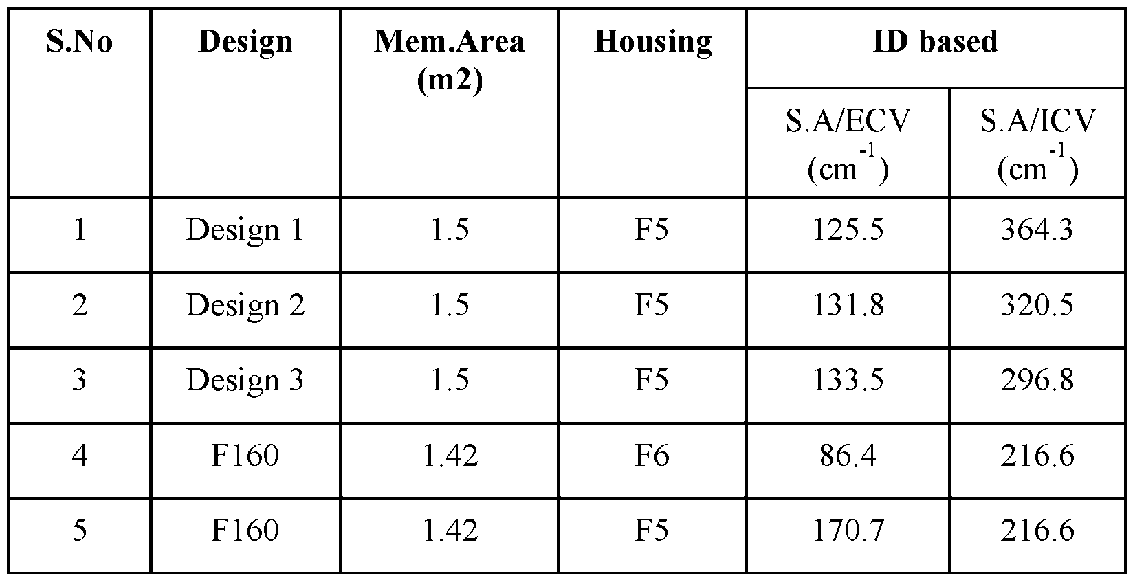
[00200] The present invention includes the following aspects/embodiments/features in any order and/or in any combination: [00201] The present invention in part relates to a porous hollow fiber membrane comprising: a. a lumen compartment, b. an inner surface adjacent to the lumen compartment, and an outer surface; c. a wall having a wall thickness of about 10 µm (micrometers) to about 30 µm; d. an inner diameter (ID) of about 90 µm to about 160 µm; e. a selective surface at the inner surface; and f. a support region adjacent to the selective surface. [00202] The porous hollow fiber membrane of any preceding or following embodiment/feature/aspect, wherein the surface area to capillary volume of the hollow fiber membrane is in the range of 250 to 450 cm
-1, or from 275 to 450 cm
-1 , or from 300 to 450 cm
-1 , or from 325 to 450 cm
-1 , or from 350 to 450 cm
-1 , or from 375 to 450 cm
-1.
Attorney Docket No: 3192-111-01 PCT [00203] The porous hollow fiber membrane of any preceding or following embodiment/feature/aspect, wherein the porosity of the membrane increases from the selective surface across the wall thickness and to the other side. [00204] The present invention also relates to a porous hollow fiber membrane comprising: a. a lumen compartment, b. an inner surface adjacent to the lumen compartment, and an outer surface; c. a wall having a wall thickness of about 10 µm (micrometers) to about 30 µm; d. an inner diameter (ID) of about 90 µm to about 160 µm; e. a selective surface at the inner surface, the outer surface, or both; and f. a support region adjacent to the selective surface, wherein the porous hollow fiber membrane has a mass density throughout the wall thickness, such that the mass density from the inner surface to the outer surface is a gradient of increasing or decreasing mass density. [00205] The porous hollow fiber membrane of any preceding or following embodiment/feature/aspect, wherein the ID is about 100 µm to about 140 µm. [00206] The porous hollow fiber membrane any preceding or following embodiment/feature/aspect, wherein the wall thickness is about 20 µm to about 26 µm. [00207] The porous hollow fiber membrane of any preceding or following embodiment/feature/aspect, wherein the outside diameter (OD) of the fiber membrane varies from 100 µm to 220 µm. [00208] The porous hollow fiber membrane of any preceding or following embodiment/feature/aspect, wherein the fiber bundle weight per unit membrane area is less than 13 g. [00209] The porous hollow fiber membrane of any preceding or following embodiment/feature/aspect, wherein the selective surface has a thickness or depth of about 1 µm
Attorney Docket No: 3192-111-01 PCT or less. [00210] The porous hollow fiber membrane of any preceding or following embodiment/feature/aspect, wherein the wall has a spongy or macrovoid morphology. [00211] The porous hollow fiber membrane of any preceding or following embodiment/feature/aspect, wherein the hydraulic permeability is greater than 50 ml/h.mmHg.m2. [00212] The porous hollow fiber membrane of any preceding or following embodiment/feature/aspect, wherein the contact angle at the inner surface is 40-90°. [00213] The porous hollow fiber membrane of any preceding or following embodiment/feature/aspect, wherein the PVP content at the inner surface as determined by XPS is greater than at the outer surface or a region between the inner surface and outer surface. [00214] The porous hollow fiber membrane of any preceding or following embodiment/feature/aspect, wherein the surface roughness, R
a of the inner surface is less than 10 nm. [00215] The porous hollow fiber membrane of any preceding or following embodiment/feature/aspect, wherein a ratio between the surface roughness, R
a of the non-selective surface to the selective surface is greater than 35. [00216] The porous hollow fiber membrane of any preceding or following embodiment/feature/aspect, wherein the hydraulic permeability is greater than about 150 ml/h.mmHg.m2. [00217] The porous hollow fiber membrane of any preceding or following embodiment/feature/aspect, wherein the hydraulic permeability is greater than about 170 ml/h.mmHg.m2. [00218] The porous hollow fiber membrane of any preceding or following embodiment/feature/aspect, wherein the hydraulic permeability is greater than about 200 ml/h.mmHg.m2.
Attorney Docket No: 3192-111-01 PCT [00219] The porous hollow fiber membrane of any preceding or following embodiment/feature/aspect, wherein the urea mass transfer coefficient, Ko is in the range of 900- 1400 mL/min per unit fiber membrane area at a flow rate of Qb = 300, Qd = 500, and Qf = 0. [00220] The porous hollow fiber membrane of any preceding or following embodiment/feature/aspect, wherein the urea mass transfer coefficient, Ko is preferably higher than 1100 mL/min/m
2 at a flow rate of Qb = 300, Qd = 500, and Qf = 0. [00221] The porous hollow fiber membrane of any preceding or following embodiment/feature/aspect, wherein the beta-2-microglobulin (B2M) mass transfer coefficient, Ko is higher than 60±15 mL/min/m
2 at a blood flow rate Qb = 300, and a dialysate flow rate Qd = 500, and ultrafiltration rate (UFR) = 0. [00222] The porous hollow fiber membrane of any preceding or following embodiment/feature/aspect, wherein the beta-2-microglobulin (B2M) mass transfer coefficient, Ko is higher than 60 mL/min/m
2 at a flow rate of Qb = 300, Qd = 500, and Qf = 0. [00223] The porous hollow fiber membrane of any preceding or following embodiment/feature/aspect, wherein the albumin sieving coefficient is less than 1% at a Qb = 300 ml/min, and UFR = 29 ml/min. [00224] The porous hollow fiber membrane of any preceding or following embodiment/feature/aspect, wherein the albumin sieving coefficient is less than 0.01% at a Qb = 300 ml/min, and UFR = 29 ml/min. [00225] The porous hollow fiber membrane of any preceding or following embodiment/feature/aspect, wherein the ratio of mass transfer coefficient of B2M to the albumin sieving coefficient is in the range of 4,500- 750,000 mL/min/m
2. [00226] The porous hollow fiber membrane of any preceding or following embodiment/feature/aspect, wherein the selective surface is present at the inner surface and the outer surface.
Attorney Docket No: 3192-111-01 PCT [00227] The porous hollow fiber membrane of any preceding or following embodiment/feature/aspect, wherein the membrane is characterized by a rate of change in porosity dP/dW, wherein P is the porosity (in percent) and W is the wall thickness (in µm). [00228] The present invention also relates to a porous hollow fiber membrane prepared from a solution comprising: at least one polyarylether polymer, at least one hydrophilic polymer, and at least one solvent, wherein the hollow fibers each have: an inner diameter of about 90 µm to about 160 µm, and a wall thickness of about 10 µm to about 30 µm; and wherein the porous hollow fiber membrane has a mass density throughout the wall thickness, such that the mass density from the inner surface to the outer surface is a gradient of increasing or decreasing mass density. [00229] The present invention also relates to a porous hollow fiber membrane for use in extracorporeal blood therapy, the membrane comprising: a. a lumenal compartment, b. an inner surface adjacent to the lumenal compartment and an outer surface; c. a wall having a wall thickness of about 20 µm (micrometers) to about 26 µm; d. an inner diameter (ID) of about 110-140 µm; e. a selective surface at the inner surface; and f. a support region adjacent to the selective surface, wherein the porosity of the membrane increases from the selective surface across the wall thickness and to the outer surface. [00230] The present invention also relates to a dialysis membrane prepared from a solution
Attorney Docket No: 3192-111-01 PCT comprising: 10 to 30 wt. % of at least one polyarylether polymer, 1 to 10 wt. % of at least one hydrophilic polymer, and at least one solvent, wherein the dialysis membrane has: a molecular weight retention onset (MWRO) of from 4.8 kDa to 5.2 kDa, and a molecular weight cut-off (MWCO) of from 24.5 kDa to 28 kDa, as determined by dextran sieving before blood contact with the dialysis membrane. [00231] In the methods of the present invention, the polymeric membrane formed from the method can have a molecular weight cut-off (MWCO) of from about 24.5 kDa to about 28 kDa such as from about 25 kDa to about 27 kDa. [00232] The present invention also relates to a method of making the porous hollow fiber membrane of any preceding or following embodiment/feature/aspect, said method comprising: a) providing a solution comprising at least one polyarylether polymer and at least one hydrophilic polymer, at least one polymer and at least one solvent; b) forming the porous hollow fiber membrane by passing said solution through a spinneret to form the porous hollow fiber membrane; c) passing said porous hollow fiber membrane from step (b) through at least one precipitation bath comprising an aqueous solution; d) passing said porous hollow fiber membrane from step (c) through at least one washing bath; e) passing said porous hollow fiber membrane from step (d) through at least one drying chamber; and f) collecting said porous hollow fiber membrane from step (e).
Attorney Docket No: 3192-111-01 PCT [00233] The method or membrane of any preceding or following embodiment/feature/aspect, wherein said forming occurs in a spinning block and said passing of said solution further comprises passing a precipitation fluid through said spinneret to form the porous hollow fiber membrane. [00234] The method or membrane of any preceding or following embodiment/feature/aspect, wherein said at least one polymer comprises at least one hydrophobic polymer and at least one hydrophilic polymer in a solvent comprising at least one polar aprotic solvent. [00235] The method or membrane of any preceding or following embodiment/feature/aspect, wherein said at least one hydrophobic polymer is poly(aryl)ethersulfone (PAES), polysulfone (PSF) or polyethersulfone (PES), or any combinations thereof. [00236] The method or membrane of any preceding or following embodiment/feature/aspect, wherein said at least one hydrophobic polymer is at least one of polysulfone (PSF), polyethersulfone (PES), polyarylsulfone (PAS), polyarylethersulfone (PAES), polyvinylidene fluoride (PVDF), polyacrylonitrile (PAN), cellulose triacetate (CT), or a copolymer thereof. [00237] The method or membrane of any preceding or following embodiment/feature/aspect, wherein said at least one hydrophilic polymer is polyvinylpyrrolidone (PVP), polyethylene glycol (PEG), polyvinyl alcohol (PVA), a copolymer of polypropylene oxide and polyethylene oxide (PPO-PEO), or any combinations thereof. [00238] The method or membrane of any preceding or following embodiment/feature/aspect, wherein said at least one polar aprotic solvent is dimethylacetamide (DMAC), N-methyl-2- pyrrolidone (NMP), dimethylsulfoxide (DMSO), diphenylsulfone (DFS), or any combinations thereof. [00239] The method or membrane of any preceding or following embodiment/feature/aspect, wherein said solution comprises from 10 wt% to about 30 wt% of the at least one hydrophobic polymer, from about 2 wt% to about 30 wt% of the at least one hydrophilic polymer, and from about 60 wt% to about 90 wt% of the at least one polar aprotic solvent.
Attorney Docket No: 3192-111-01 PCT [00240] The method of any preceding or following embodiment/feature/aspect, wherein said spinning block comprising the at least one spinneret having an external ring duct for the solution (spin mass) and a hollow core through which a precipitating solution is simultaneously fed. [00241] The present invention also relates to a method to form the porous hollow fiber membrane polymeric fibers of any preceding claims, said method comprising supplying a spin mass to a spinneret simultaneously with a bore fluid and casting polymeric fibers, wherein said spin mass comprises at least one polymer and at least one organic solvent and said bore fluid comprises at least one aqueous solvent and/or at least one organic solvent. [00242] The present invention also relates to a method for manufacturing a hollow fiber membrane of any preceding or following embodiment/feature/aspect, said method comprising the method steps: • preparing at least one spin mass comprising a hydrophobic and a hydrophilic polymer, at least one aprotic polar solvent, • preparing at least one precipitation fluid or coagulant comprising at least one aprotic polar solvent and/or at least one non-solvent (e.g., water), • conveying the spin mass through at least one annular gap of a spinneret into a hollow strand, • conveying the precipitation fluid through a central bore of the spinneret into the lumen of the strand, • introducing the strand into a precipitating bath and obtaining the hollow fiber membrane. [00243] The present invention also relates to a method for manufacturing the hollow fiber membrane of any preceding or following embodiment/feature/aspect, said method comprising:
Attorney Docket No: 3192-111-01 PCT • providing a spin mass or spinning solution comprising a polysulfone-based material, in particular polysulfone, a vinylpyrrolidone-based polymer, in particular polyvinylpyrrolidone, an aprotic solvent, in particular dimethylacetamide, • providing a precipitation fluid or coagulant liquid comprising water and an aprotic solvent, in particular dimethylacetamide, • co-extruding the spinning solution and the coagulant liquid through a concentric annular spinneret into a hollow strand, whereby the cavity of the strand is filled with coagulant liquid, • conducting the strand through a precipitation gap, • introducing the strand into a precipitating bath comprised substantially of water so as to obtain the porous hollow fiber membrane, • conducting the hollow fiber membranes through at least one rinsing bath and drying the hollow fiber membrane obtained, and optionally • arranging the resulting hollow fiber membranes into a hollow fiber membrane bundle. [00244] The method of any preceding or following embodiment/feature/aspect, wherein the draw ratio is increased by at least 50% as compared to conventional hollow fiber membranes. [00245] The method of any preceding or following embodiment/feature/aspect, wherein the draw ratio is increased by 60-110% as compared to conventional hollow fiber membranes. [00246] The method of any preceding or following embodiment/feature/aspect, wherein the draw ratio is greater than 2.2 and the speed of bore fluid/dope solution leaving spinneret is greater than 0.9. [00247] The present invention also relates to a dialyzer comprising a cylindrical housing with three compartments, a plurality of porous hollow fiber membranes within said housing, a first compartment defined by the internal wall of the housing having a total housing volume (HV), a
Attorney Docket No: 3192-111-01 PCT second compartment within the plurality of porous hollow fiber membranes, the plurality of porous hollow fiber membranes having a total membrane surface area (SA), and third compartment is the volume of the housing not occupied by the plurality of porous hollow fibers (IV, dialysate volume), wherein the porous hollow fiber membranes comprise: a. an outer surface, an inner surface, and a wall having a wall thickness measured from the outer surface to the inner surface; b. a lumen compartment, c. the wall thickness of about 10 µm to about 30 µm; d. an inner diameter (ID) of about 90 µm to about 160 µm; e a selective surface at the inner surface, the outer surface, or both; and f. a support region adjacent to the selective surface, wherein the dialyzer SA/HV ratio is greater than 60 cm
-1. [00248] The dialyzer of any preceding or following embodiment/feature/aspect, wherein SA/HV is greater than 65 cm
-1. [00249] The dialyzer of any preceding or following embodiment/feature/aspect, wherein SA/HV is greater than 70 cm
-1. [00250] The dialyzer of any preceding or following embodiment/feature/aspect, wherein SA/HV is between 60 cm
-1 and 90 cm
-1 or from 60 cm
-1 and 140 cm
-1. [00251] The dialyzer of any preceding or following embodiment/feature/aspect, wherein the SA/blood volume ratio is higher than 250 cm
-1. [00252] The dialyzer of any preceding or following embodiment/feature/aspect, wherein the porosity of the membrane increases from the selective surface across the wall thickness and to the other surface. [00253] The dialyzer of any preceding or following embodiment/feature/aspect, wherein the urea mass transfer coefficient, Ko is in the range of 900 to 1400 mL/min/m
2.
Attorney Docket No: 3192-111-01 PCT [00254] The dialyzer of any of the preceding claims, wherein the packing density is between 35% to 70%. [00255] The dialyzer of any preceding or following embodiment/feature/aspect, wherein the sieving coefficient of human albumin is between 0.01% to 1.0% at a Qb = 300 ml/min, and UFR = 29 ml/min. [00256] The dialyzer of any preceding or following embodiment/feature/aspect, wherein the mass transfer coefficient of B2M is 60±15.0 mL/min/m
2 flow rate of Qb = 300, Qd = 500, and Qf = 0. [00257] The dialyzer of any preceding or following embodiment/feature/aspect, wherein a ratio between the mass transfer coefficient of B2M to the sieving coefficient for human albumin is in the range of 4,500 to750,000 mL/min/m
2. [00258] The dialyzer of any preceding or following embodiment/feature/aspect, wherein the transmembrane pressure drop from one end of the dialyzer to the other end of the dialyzer is in the range of 100 to 1000 mm Hg when the flow rate varies from 100 to 600 mL/min. [00259] The dialyzer of any preceding or following embodiment/feature/aspect, wherein the transmembrane pressure drop from one end of the dialyzer to the other end of the dialyzer is in the range of 200 to 300 mm Hg when the flow rate varies from 100 to 600 mL/min. [00260] The dialyzer of any preceding or following embodiment/feature/aspect, wherein the mass transfer coefficient, Ko of urea is preferably greater than 1100 mL/min/m
2 at a flow rate of Qb = 300, Qd = 500, and Qf = 0. [00261] The dialyzer of any preceding or following embodiment/feature/aspect, wherein the dialyzer comprises greater than 12,000 hollow fiber membranes. [00262] The dialyzer of any preceding or following embodiment/feature/aspect, wherein the dialyzer comprises greater than 10,000 hollow fiber membranes. [00263] The dialyzer of any preceding or following embodiment/feature/aspect, wherein the
Attorney Docket No: 3192-111-01 PCT dialyzer comprises about 15,000 to about 22,000 hollow fiber membranes. [00264] The dialyzer of any preceding or following embodiment/feature/aspect, wherein the effective fiber length to the fiber inner diameter (ID) ratio is in the range of 1400 to 2700 or 2200 to 2700. (The fiber length for instance can be 225600 µm or within 30%, or within 20%, or within 10%, or within 5%, or within 1% of this length). [00265] The dialyzer of any preceding or following embodiment/feature/aspect, wherein the effective fiber length to the fiber inner diameter (ID) ratio is in the range of 1400 to 3250 or in the range of 1840 to 3250. (The fiber length for instance can be 294000 µm or within 30%, or within 20%, or within 10%, or within 5%, or within 1% of this length). [00266] The dialyzer of any preceding or following embodiment/feature/aspect, wherein the sodium clearance is in the range of 270 -292 mL/min when the membrane area changes from 1.0 to 1.5 m
2 at a Qb = 300 ml/min, Qd = 500 ml/min, and Qf=0. [00267] The dialyzer of any preceding or following embodiment/feature/aspect, wherein the dialyzer has a vitamin B12 clearance is in the range from 170 ml/min to 215 ml/min when the membrane area changes from 1.0 to 1.5 m
2 at a Qb = 300, Qd = 500, and Qf = 0. [00268] The dialyzer of any preceding or following embodiment/feature/aspect, wherein the dialyzer has a creatinine clearance is in the range from 245 ml/min to 280 ml/min when the membrane area changes from 1.0 to 1.5 m
2 at a Qb = 300, Qd = 500, and Qf = 0. [00269] The dialyzer of any preceding or following embodiment/feature/aspect, wherein the albumin sieving coefficient is less than 0.05% at a Qb = 300 ml/min, Qd = 500 ml/min, and UFR = 29 ml/min. [00270] The dialyzer of any preceding or following embodiment/feature/aspect, wherein the dialyzer has a molecular weight retention onset (MWRO) of from 4.8 kDa to 5.2 kDa as determined by dextran sieving before blood contact with the dialysis membrane. For purposes of the present invention, the MWRO can be based or determined using a dextran solution in water and following
Attorney Docket No: 3192-111-01 PCT DIN EN 1508637:2014. [00271] The dialyzer of any preceding or following embodiment/feature/aspect, wherein the dialyzer has a molecular weight cut-off (MWCO) of from 24.5 kDa to 28 kDa as determined by dextran sieving before blood contact with the dialysis membrane. This MWCO can be a value for describing the retention capabilities of the membrane and refers to the molecular mass of a solute where the membrane has a rejection of 90%, corresponding to a sieving coefficient of 0.1. The MWCO can also be described as the molecular mass of the solute, such as for example dextrans or proteins, at which the membrane allows passage of 10% of these molecules. For purposes of the present invention, the MWCO can be based or determined using a dextran solution in water and following DIN EN 1508637:2014. [00272] The dialyzer of any preceding or following embodiment/feature/aspect, wherein the dialyzer is e-beam or steam sterilized. [00273] A method of hemodialysis, the method comprising passing blood through a first chamber of a dialysis filter comprising the dialysis membrane or dialyzer of any preceding claim, such that the blood contacts a first side of the hollow fiber membrane; and passing a dialysis solution through a second chamber of the dialysis filter such that the dialysis solution contacts a second opposite side of the hollow fiber membrane to remove waste products from the blood, wherein the first chamber is inside the hollow fiber membrane and the second chamber is between the hollow fiber membrane and an inner wall of the dialysis filter. [00274] A method of hemodialysis, the method comprising passing blood through a first chamber of a dialysis filter comprising the dialysis membrane or dialyzer of any preceding claim, such that the blood contacts a first side of the hollow fiber membrane; and passing a dialysis solution through a second chamber of the dialysis filter such that the dialysis solution contacts a second opposite side of the hollow fiber membrane to remove waste products from the blood, wherein the second chamber is inside the hollow fiber membrane and the first chamber is between
Attorney Docket No: 3192-111-01 PCT the hollow fiber membrane and an inner wall of the dialysis filter. [00275] The method of any preceding or following embodiment/feature/aspect, wherein the membrane is configured to pass blood through the inside of hollow fibers. [00276] The method of any preceding or following embodiment/feature/aspect, wherein the pore size across the wall thickness progressively increases from the selective surface through the support region and to the opposite surface. [00277] The method of any preceding or following embodiment/feature/aspect, wherein the membrane is prepared from a solution comprising: at least one polyarylether polymer, at least one hydrophilic polymer, at least one solvent, and wherein the hollow fibers each have an inner diameter of from about 90 µm to about 140 µm; and a wall thickness of from about 20 µm to about 28 µm. [00278] The porous hollow fiber membrane or method of any preceding or following embodiment/feature/aspect, wherein the membrane is characterized by a rate of change in porosity dP/dW, wherein P is the porosity (in percent) and W is the wall thickness (in µm). [00279] The porous hollow fiber membrane or method of any preceding or following embodiment/feature/aspect, wherein dP/dW, as measured within a region that is no less than ¼ of the thickness of the membrane wall, is at least 5.0 %/µm. [00280] The porous hollow fiber membrane or method of any preceding or following embodiment/feature/aspect, wherein dP/dW, as measured within a region that is no less than ¼ of the thickness of the membrane wall, is at least 8.0 %/µm. [00281] The porous hollow fiber membrane or method of any preceding or following embodiment/feature/aspect, wherein dP/dW, as measured within a region that is no less than ¼ of the thickness of the membrane wall, is at least 10.0 %/µm.
Attorney Docket No: 3192-111-01 PCT [00282] The porous hollow fiber membrane or method of any preceding or following embodiment/feature/aspect, wherein dP/dW, as measured within the first ¼ of the thickness of the membrane wall closest to the active surface, is at least 5.0 %/µm, or at least 8.0 %/µm, or at least 10.0 %/µm. [00283] The porous hollow fiber membrane or method of any preceding or following embodiment/feature/aspect, wherein beneath the selective surface, there is a region of thickness, no less than 2 micron in thickness, where a slope of increasing porosity is at least 5.0 %/µm (or at least 8.0 %/µm, or at least 10.0 %/µm). [00284] The porous hollow fiber membrane or method of any preceding or following embodiment/feature/aspect, wherein dP/dW, as measured within a region that is no less than ¼ of the thickness of the membrane wall, is from 5.0 %/µm to 20 %/µm, or from 8.0 %/µm to 20 %/µm, or from 10 %/µm to 20 %/µm, or from 5.0 %/µm to 18 %/µm, or from 8.0 %/µm to 18 %/µm, or from 10 %/µm to 18 %/µm. [00285] The porous hollow fiber membrane or method of any preceding or following embodiment/feature/aspect, wherein dP/dW, as measured within the first ¼ of the thickness of the membrane wall closest to the active surface, is from 5.0 %/µm to 20 %/µm, or from 8.0 %/µm to 20 %/µm, or from 10 %/µm to 20 %/µm, or from 5.0 %/µm to 18 %/µm, or from 8.0 %/µm to 18 %/µm, or from 10 %/µm to 18 %/µm. [00286] The porous hollow fiber membrane or method of any preceding or following embodiment/feature/aspect, wherein beneath the selective surface, there is a region of thickness, no less than 2 micron in thickness, where a slope of increasing porosity is from 5.0 %/µm to 20 %/µm, or from 8.0 %/µm to 20 %/µm, or from 10 %/µm to 20 %/µm, or from 5.0 %/µm to 18 %/µm, or from 8.0 %/µm to 18 %/µm, or from 10 %/µm to 18 %/µm. [00287] The present invention can include any combination of these various features or embodiments above and/or below as set forth in sentences and/or paragraphs. Any combination of
Attorney Docket No: 3192-111-01 PCT disclosed features herein is considered part of the present invention and no limitation is intended with respect to combinable features. [00288] Applicants specifically incorporate the entire contents of all cited references in this disclosure. Further, when an amount, concentration, or other value or parameter is given as either a range, preferred range, or a list of upper preferable values and lower preferable values, this is to be understood as specifically disclosing all ranges formed from any pair of any upper range limit or preferred value and any lower range limit or preferred value, regardless of whether ranges are separately disclosed. Where a range of numerical values is recited herein, unless otherwise stated, the range is intended to include the endpoints thereof, and all integers and fractions within the range. It is not intended that the scope of the invention be limited to the specific values recited when defining a range. [00289] Other embodiments of the present invention will be apparent to those skilled in the art from consideration of the present specification and practice of the present invention disclosed herein. It is intended that the present specification and examples be considered as exemplary only with a true scope and spirit of the invention being indicated by the following claims and equivalents thereof.
 Attorney Docket No: 3192-111-01 PCT where ΔfHb = fHb(t =240*) - fHb(t =5) (mg/dL) V= volume recirculated (mL) %HCT= Averaged % Hematocrit (HCT) Qb = Blood flow rate (mL/min) ΔT = Sampling time interval (min). The MIH equation used is provided below. The MIH equation produces a very small number so the final values are raised to the 106 to reduce the decimal places. ^^^^^^^^^^^^^^^^ ∗ ^^^^ ∗ (100 − %^^^^^^^^^^^^) ^^^^^^^^^^^^ = 100 ^^^^^^^^ ∗ ^^^^^^^^ ∗ ^^^^^^^^^^^^ The parameters of the equation are as follows: Where ΔfHb = fHb(t =240*) - fHb(t =5) (mg/dL) V= volume of blood recirculated (mL) %HCT= Averaged % Hematocrit (HCT) Qb = Blood flow rate (mL/min) tHb = total hemoglobin (mg/dL). The % of hemolysis index was calculated using the following equation,
 100 Where ΔfHb = fHb(t =240*) - fHb(t =5) (mg/dL) tHb = total hemoglobin (mg/dL). [00165] EXAMPLE 1 – Comparative Example [00166] Conventional hollow fiber membranes (ID ~185 µm, wall thickness ~35 µm) were prepared using wet spinning annular spinnerets having an outer diameter D1 of 0.4 mm and inner diameter D2 of 0.2 mm. Spinning dope solution was prepared by dissolving 16 wt% polysulfone P3500 (PS, from Solvay) and 4 wt% polyvinylpyrrolidone K90 (PVP) in Dimethylacetamide (DMAC) under agitation. Spinning dope was processed into a homogeneous mixture and extruded through the outer ring of the spinneret along with a centrally controlled precipitant (bore fluid) that was fed into the interior of the hollow strand. In this case, the bore fluid was a DMAC solution containing 45.5 wt% water. The spinneret annular gap width was 50 μm with an inner diameter
Attorney Docket No: 3192-111-01 PCT of 200 μm. The temperature of the spinneret and precipitation bath, draw ratio, and other parameters are shown in Table 1 below. The extruded strand was guided through a precipitant chamber into a water precipitation bath heated to approximately 63° C, where it precipitated into a hollow fiber membrane. The air gap was 30 mm. The hollow fiber membrane was subsequently guided through rinsing baths kept at a temperature of 75° C to 90° C. A bundle of 10,752 such fibers, each having a length of approximately 22.6 cm, were collected and introduced into the housing of a hollow fiber membrane dialyzer having an inner diameter of 40.08 mm. The ends of the hollow fiber membranes were potted in the housing of the hollow fiber membrane dialyzer as generally known in the art, so that a first chamber (blood side) was formed within the collective lumenal space of the hollow fibers and a second chamber (dialysate side) was formed between the outer surface of the hollow fibers and the inner wall of the housing. The dialyzer was sterilized using electron beam (e-beam) radiation. The total membrane area (A) of the hollow fiber bundle in the dialyzer housing was 1.4 m2 at a pack factor (PF) of 44%. [00167] EXAMPLE 2 – Inventive Example [00168] Hollow fiber membranes were made according to Example 1, except that fibers with reduced ID of about 135 µm were made (Design 3). The spinning conditions and fiber properties are reported in Table 1. As shown, dope flow rate (Qd), bore fluid flow rate (Qb), dope fluid velocity (Vd) and bore fluid velocity (Vb) at the spinneret are significantly reduced compared to Example 1, while draw ratio (DR) is significantly increased (over 65%). The ID was 138.7 µm, wall thickness was 25.9 µm, and Aspect Ratio (F-ID/F-W) was 5.36. [00169] EXAMPLE 3 – Inventive Example [00170] Hollow fiber membranes were made according to Example 2 except that a bore fluid of 43.3 wt% water was used to precipitate the fibers, with minimal changes to other spinning parameters. The ID was about 138 µm or 137.1 µm (Design 3), wall thickness was 26.4 µm, and
Attorney Docket No: 3192-111-01 PCT Aspect Ratio (F-ID/F-W) was 5.19. The spinning conditions and dialyzer performance are reported in Table 1. [00171] EXAMPLE 4 – Inventive Example [00172] Hollow fiber membranes of similar membrane area were made according to Example 1 but with various water concentrations in the bore fluid to change the permeability of the membrane, and further reduced dope fluid flow rate (Qd) and bore fluid flow rate (Qb) leading to fiber with smaller dimension of about 110 µm ID (Design 1). Results are shown in Table 1. The overall mass transfer coefficient of sodium as a function of bore fluid water percentage (blood flow rate = 300 ml/min, dialysate flow rate = 500 ml/min) is plotted in FIG.3. [00173] EXAMPLE 5 – Inventive Example [00174] Hollow fiber membranes were made according to Example 1, except that the bore fluid composition was 44.2 wt% water and different dope fluid flow rate (Qd) and bore fluid flow rate (Qb) were used leading to fiber with small dimension of about 125 µm ID (Design 2). Results are shown in Table 1. [00175] Example 6 – Inventive Example [00176] Hollow fiber membranes were made according to Example 1 with the following changes: 1) the PVP content in spinning dope was increased by 0.3 wt%, 2) Vitamin E was added to spinning dope at 0.01 wt%, 3) a bore fluid of 55 wt% water containing 0.15% PVP was used to precipitate the fibers, 4) a smaller housing was used with an effective length of 29 cm and inner diameter of 25.8 mm to house the fiber. Results and additional parameters are shown in Table 1. [00177] For each of Examples 2 through 6 (Inventive Examples), sections of the membrane (fiber) were imaged at 50,000 magnification and at various layers within the membrane, and these layers were analyzed using ImageJ analysis. For these membranes, the active surface was at the inner surface of the porous hollow fiber membrane and a non-active region or support region was further present and adjacent to the active surface. Based on the ImageJ analysis, the
Attorney Docket No: 3192-111-01 PCT membrane wall had a generally asymmetric architecture, and the porous hollow fiber membrane had a porosity such that the porosity of the membrane increased from the active surface (inner surface) across the wall thickness and to the outer surface. Further, the porous hollow fiber membrane had a mass density through the wall thickness, such that the mass density from the inner surface to the outer surface was essentially a gradient of decreasing mass density. [00178] dP/dW within the first ¼ of the thickness of the membrane, closest to the active surface, was determined for the membranes of Example 1 (4.5 %/µm), Example 5 (8.1 %/µm), and Example 6 (10.2 %/µm). [00179] Between 10,000 and 20,000 hollow fiber membranes prepared according to Examples 1-6 were bundled and assembled into polycarbonate dialyzer housings, sealed, and e-beam sterilized as described. Total membrane surface area (A) was between 1.3 m2 and 1.6 m2. Housing volume was calculated as total internal volume of the housing within the dialyzer compartment. Membrane surface area to housing volume was calculated and it was determined that inventive dialyzers (Examples 2-6, 65-80 cm-1) had significantly higher A/HV ratios than the comparative dialyzer (Example 1, 50 cm-1). [00180] The Examples accordingly demonstrate a range of conditions in hollow fiber membrane production leading to a range of ID values and wall thicknesses.
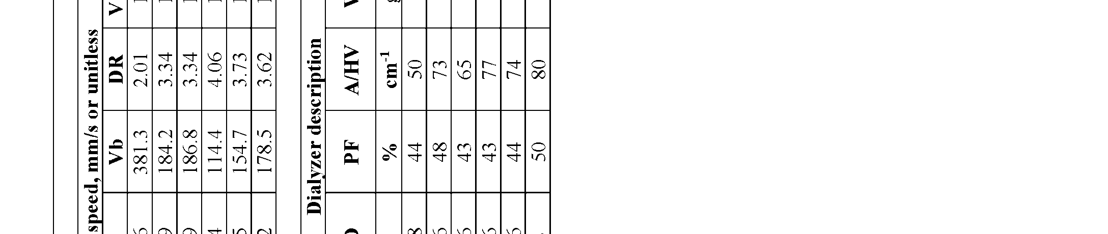 ar e r n i t e n n i b
 p- W d 7 . 9 . 9 . 7 6 . 9 . L 6 . 6 . 6 . 6 6 T Q9 1 1 1 1 1 . 9 0 1 0 1 - F m c 2 2 2 2 2 . 2 2 . 2 2 9 2 2 n oi t P 5 p i V 0 0 0 0 0 1 r m 2 5 0 6 4 2 8 6 6 9 2 5 P . c u 0 s e N 7 - , 0 3 5 8 1 3 9 1 9 8 6 7 , 0 D F 1 1 1 1 r e b ) C i r e A5 . 5 7 F b i f M4 . 5 4 . 8 5 6 . 8 5 . 5 5 4 R 1 A 5 6 . 3 9 . 1 1 . 8 0 . 3 2 . 8 . y b D 5 5 5 5 5 5 4 5 4 d e i p u c O 2 5 . 5 H5 . 3 . 2 . 2 . 1 . 9 . 4 . 1 . 9 c . 8 o 4 5 4 3 4 4 4 4 5 W 4 5 - F m µ 4 . 3 5 2 6 2 3 2 3 2 5 2 s i t a h t g n E.t 1 9 . 7 . 1 . 1 . 6 5 i s i 0 0 0 0 0 0 . D I - m 7 8 7 1 . 6 . 4 r e u t o V 0 F µ 8 1 3 1 3 1 1 1 2 1 2 1 e h ma n i i d e C e m A0 7 8 0 8 0 8 0 8 0 8 . 9 g r c u e t r 3 p 6 6 . 4 4 . 5 2 . 5 2 . 4 4 e . 6 . r d e s a t i u s l o M 7 n i D n a ) - 2 6 3 6 3 6 3 6 3 6 2 t s e r h n i V ( n r i e C T 7 e e a g p ° ( m n e i e g n r o e P p a V 4 4 4 4 4 3 . S m s 7 1 9 2 2 1 i d k c i n a r wi s t c m u P 4 r e - . . . . . . e T T0 b 4 1 4 0 4 1 4 1 4 0 7 e d h t l t n h t b e l d u o a f l i E h k o F S . n i i s l n i a u g wo n m c e l e n m u r e c a v g P 6 1 6 1 6 1 6 1 6 1 6 1 …r i p mr e r r r l b z p n i a r y l r s Aa g m c 0 3 6 2 6 2 6 2 6 2 0 2 ati b e e e Vi b F i b b t e F i F i F o b a i e b u o T i F Di F H et : : : : : : t : : : o E DWm L - - A WDF V 1 2 3 4 5 .t I - - u I - P x - - - - 6- 1- 2- 3- 4- 5- 6- Ni F F N F H H E x E x E x E x E x E x E x E x E x E x E x E V - F
Attorney Docket No: 3192-111-01 PCT Without wishing to be bound to theory, a F-ID/F-W aspect ratio between 4.5 and 5.5 may be associated with improved membrane structural stability and performance, particularly where the F- ID is already below 30 µm (i.e., thin-walled fibers). [00181] EXAMPLE 7. [00182] Dialyzers prepared from the hollow fiber membranes of Examples 2 (“Design 3”, ID ~137 µm or 138 µm), 4 (“Design 1”, ID ~110 µm), and 5 (“Design 2”, ID ~125 µm) were conditioned and e-beam sterilized in conventional housing to determine clearance (ml/min) as a function of Kuf (with A = 1.5 m2, n = 2-3) or membrane surface area (n = 2-3). Blood was run in the conventional blood- inside configuration for testing, all dialyzers had similar pack factor (PF), and were in the same size housing (“F5 housing”, housing ID 1.34 inches, Fresenius Medical Care, Waltham, MA) the analytes included sodium (FIGS.4A, 4B), creatinine (FIGS.5A, 5B), Vitamin B12 (FIGS.6A, 6B), and β2- microglobulin (B2M) (FIG.7), as well as the albumin sieving coefficient (FIGS.8A, 8B). All tests were performed at a blood flow rate (Qb) = 300 ml/min, dialysate flow rate (Qd) = 500 ml/min, and ultrafiltration rate (UFR) = 0.0 ml/min, where relevant, except albumin sieving (Qb = 300 mL/min, UFR = 29 mL/min). The reference value of the Optiflux F160NRe dialyzer at a raw fiber Kuf/m2 = 160 and/or a membrane surface area of 1.5 m2 is shown for comparison. For B2M, the values reported are for conditioned and e-beam sterilized Skinny Fiber dialyzer Design 1 (ID ~110 µm, wall ~23 µm) and Design 3 (ID ~138 µm, wall ~26 µm), at various Kuf values (A = 1.5 m2, n = 2). [00183] The data demonstrates that Skinny fiber dialyzers have excellent small (e.g., sodium) and middle molecule (B2M > 65 ml/min, at 1.5 m2) clearance while maintaining low or very low albumin sieving coefficients (<0.01). The data collectively shows that a Skinny Fiber dialyzer can achieve the same or better performance to a conventional dialyzer having a significantly higher surface area. For example, the creatinine clearance of the Optiflux F160NRe dialyzer (A = 1.5 m2) is 242 ml/min, while the creatinine clearance of the Skinny Fiber Dialyzer Design 3 (ID ~138 µm) at a lower A = 1.18 m2 is about 250 ml/min (FIG.5B).
Attorney Docket No: 3192-111-01 PCT [00184] FIG. 9A shows the reported clearance performance of various Fresenius Medical Care dialyzers for sodium, creatinine and Vitamin B12, with their respective membrane surface areas (1.5- 2.5 m2). FIG. 9B shows the clearance performance of three designs of the Skinny Fiber dialyzer (Design 1 = 110 µm ID; Design 2 = 125 µm ID, Design 3 = 138 µm ID) at either 1.1 m2 or 1.5 m2. The Skinny Fiber dialyzers were each conditioned and e-beam sterilized, with a bundle weight of 18.0 grams (+/- 1.2 grams) at membrane area = 1.5 m2 (albumin SC < 0.20%, Qb = 500 ml/min, Qd = 300 ml/min). The data suggests that the reference Optiflux F250 dialyzer with 2.5 m2 of membrane area could be replaced with a Skinny Fiber dialyzer of 1.5 m2, and the current Optiflux F160NRe with 1.5 m2 of membrane area could be replaced with a Skinny Fiber dialyzer of 1.1 m2. [00185] Example 8. Pressure Drop. [00186] The end-to-end pressure drop was measured at different flow rates using the membranes of Example 1 (comparative) and Example 5 (ID ~125 µm, thickness ~25 µm). Packing density was about 46% in each dialyzer, with membrane area about 1.5 m2, with blood running inside the fibers (conventional configuration), but the inventive membranes were housed in F5 housing and the comparative Optiflux membranes were housed in F6 housing (housing ID 1.58 inches). FIG.10 shows the pressure drop vs. flow rate for each dialyzer. Both theoretical (dotted lines) and experimentally measured values (solid lines) are shown to demonstrate that the theoretical values are consistent with actual measured values. The data suggests that at a given flow rate, pressure drop across Skinny Fiber dialyzer (ID ~125 µm) is approximately 2.5 times higher than across the conventional dialyzer (here, the Optiflux 160). [00187] Example 9. Hemocompatability. [00188] Hemocompatability and hemolysis were evaluated for the Skinny Fiber dialyzer. [00189] In brief, the experimental dialyzer of Design 1 (ID about 110 µm or ~107 µm, wall 22.95 µm) at a total membrane area of 1.5 m2 packed in an F5 housing (n=3) was tested for platelet reduction, PF-4 activation, TAT activation, and sC5b-9 activation in a blood-inside configuration
Attorney Docket No: 3192-111-01 PCT at a blood flow rate Qb = 100 ml/min. Design 1 was chosen because it represents the smallest diameter experimental (skinny) fiber tested and would be expected to have the highest hemocompatibility risk associated, for example, with shearing effects. The results are shown in FIG.11. Reference plots for the comparative F160NRe dialyzer (A = 1.5m2) are also shown (For purposes of this data, the F160 designation, if used here, is equivalent or the same as reference to F160NRe and F160NR). In Table 3, a similar meaning applies to the other dialyzers shown in the table- F180, F200, and F250). The data shows that the hemocompatibility of the experimental dialyzer is comparable to the conventional dialyzer. [00190] The experimental dialyzer of Design 3 (ID about 137 µm or ~138 µm, wall 26 µm) at a total membrane area of 1.5 m2 packed in an F5 housing (n=3) was tested for mechanical hemolysis in a blood-inside configuration at a blood flow rate Qb = 600 ml/min. The results are shown in FIG.12, including Plasma Free Hemoglobin, fHb (FIG.12A), Hemolysis Index /HI (FIG. 12B), the Modified Index of Hemolysis/MIH (FIG. 12C), and Hemolysis Index (FIG. 12D). Reference results for the comparative F160NRe dialyzer (A = 1.5 m2) are also shown. The data shows that hemolysis in the experimental dialyzer is comparable to the conventional dialyzer. [00191] Example 10. Mass Transfer Coefficient. [00192] The mass transfer coefficient for sodium was measured as a function of membrane area Na Ko (ml/min.m2) in dialyzers prepared from the hollow fiber membranes of Examples 1-6. Mass transfer is primarily a diffusional process and is primarily impacted by membrane thickness. Because the wall of the inventive membrane is thinner, the mass transfer coefficients for the inventive membranes in Examples 2-6 are about 18-65% higher compared to Example 1. However, this difference and cost benefit of skinny fiber is magnified when the mass transfer coefficient is normalized by the bundle weight (wt) of the fiber as seen in Table 2. The weight normalized Ko or Ko/Wt for Examples 2-6 became 46 to 140% higher compared to Example 1.
Attorney Docket No: 3192-111-01 PCT Table 2. Na Ko, ml/min.m2 Na Ko /Wt
 [00193] Comparing the sodium transfer Ko of the skinny fiber in Table 2 to the urea transfer Ko (sodium is often used as the marker for urea) of several other market dialyzers shown in Table 3, it is also apparent that the Ko of the inventive (“skinny”) fiber is higher than conventional dialyzers shown. Table 3. Mem. Ko Ko Urea 2 A Urea 2 ) Qb
 Attorney Docket No: 3192-111-01 PCT [00194] These results also indicate that the inventive dialyzer has a higher mass transfer coefficient for urea per m2 of membrane area than any competitor dialyzer evaluated. [00195] Example 11. Comparative Sodium Clearance. [00196] Sodium clearance (ml/min) was evaluated for the inventive dialyzer Designs 1, 2, and 3 at 1.5 m2 membrane area and compared against several other market dialyzers of various membrane areas, the Optiflux F160NRe (1.5 m2), F180 (1.7 m2), F200 (1.9 m2), and F250 (2.5m2) (Fresenius Medical Care); FX Coral 50 (1.5 m2) (Fresenius Medical Care); and Theranova 400 (1.7 m2) and Theranova 500 (1.9 m2) (Baxter Intl., Deerfield, IL). The results shown in FIG.13 demonstrate that the inventive dialyzers have higher sodium clearance than comparable dialyzers of the same size (i.e., same membrane surface area) and even have higher sodium clearance than most of the larger dialyzers evaluated. [00197] Example 12. Surface area to Housing Volume Ratio. [00198] The inventive dialyzers Designs 1, 2, and 3 were evaluated for the ratio of membrane surface area to housing volume. This was calculated in multiple ways to capture different aspects. Results are shown in Table 4 below. As shown, the surface area to housing volume ratio (measured either as ECV or ICV) in the inventive dialyzers is significantly greater than conventional dialyzers using the same housing. The ECV is a reference to the external capillary space volume (external capillary volume), which means the remaining volume/space left after the given housing is loaded with fiber membrane to the desired area. The ratio of surface area to this amount of left over volume/external capillary volume is determined and identified as SA/ECV. The ICV is the internal capillary space volume (internal capillary volume), which means the volume of liquid/blood required to fill all of the fibers in the housing/dialyzer. The ratio of surface area of the membranes to the ICV is identified as SA/ICV. The ECV can be understood to be the dialysate volume required to fill a dialyzer and ICV can be understood to be the blood volume required to fill that same dialyzer.
Attorney Docket No: 3192-111-01 PCT [00199] Table 4. Comparison of the surface area to capillary space volumes ratios (both external and internal) of skinny fiber dialyzers with F160NRe dialyzers. The * means that the surface area was calculated based on the inner diameter of the fiber. S.No Design Mem.Area Housing ID based (m2)