Attorney Docket No.: SP23-321 D
ESIGNED BOTTOM AND FLANGE RING-OFF BREAKAGE OF STRENGTHENED GLASS CONTAINERS VIA GEOMETRICAL FEATURES CROSS-REFERENCE TO RELATED APPLICATIONS
[0001] This application claims the benefit of priority under 35 U.S.C. §119 of U.S. Provisional Application Serial No. 63/600,949 filed on November 20, 2023, and U.S. Provisional Application Serial No. 63/547,919 filed on November 9, 2023, the content of which are relied upon and incorporated herein by reference in their entirety. T
ECHNICAL FIELD [0002] The present specification generally relates to glass containers and, more specifically, to glass pharmaceutical containers formed with features to assure the sterility of pharmaceutical contents stored therein. BACKGROUND
[0003] A concern for food and drug manufacturers is maintaining the sterility of package contents from failing during transport and storage until patient use. While glass containers are superior to many alternative materials, they are not unbreakable and occasionally experience damage from handling and transport. Cracks that extend through the wall thickness may form, compromising the sterility of the contents but not leading to catastrophic failure of the package. Such cracks may result in recalls when detected by a health care professional or end consumer at the point of use, and can be costly to the pharmaceutical or foodstuff manufacturer.
[0004] Accordingly, a need exists for alternative designs for glass containers for use in storing pharmaceutical products. SUMMARY
[0005] The present disclosure provides a strengthened glass container or vessel such as, but not limited to, vials for holding pharmaceutical products or vaccines, and foodstuff containers (e.g., bottles, baby food jars, etc.) in a hermetic and/or sterile state. The strengthened glass container undergoes a strengthening process that produces compression at the surface and tension within the container wall. The strengthened glass container is provided with geometrical features such that when the glass container undergoes the strengthening process,
Attorney Docket No.: SP23-321 the resulting residual stress profile favors desirable crack propagation behaviors. According to embodiments described herein, the crack propagation behavior of the strengthened glass container is controlled so as to promote catastrophic failure of the container, thus rendering the product unusable, should sterility be compromised by a through-wall crack.
[0006] In particular, the strengthened glass containers of the present disclosure comprise a region of modified thickness which, in conjunction with a strengthening process, promotes the formation of a circumferential crack propagation zone conducive to desirable breakage patterns. Such desirable breakage patterns typically involve cracks propagating circumferentially around the glass container, thereby yielding bottom-ring-off (BRO) or flange-ring-off (FRO) breakage patterns.
[0007] According to a first aspect of the present disclosure, a strengthened glass container comprises: a cylindrical body portion with a first end and a second end, the cylindrical body portion comprising an outer diameter (D) and a sidewall having a sidewall thickness (h); a curved heel extending radially inward from the first end of the cylindrical body portion; and a bottom extending from the curved heel and closing the cylindrical body portion at the first end of the cylindrical body portion, the bottom comprising a peak bottom thickness (h
b,peak). A ratio between the peak bottom thickness (h
b,peak) and the sidewall thickness (h) is greater than or equal to 1.3.
[0008] A second aspect includes the first aspect, further comprising a protuberance in the bottom of the strengthened glass container, wherein the protuberance comprises a ring of thickened glass relative to a remaining portion of the bottom, and wherein the protuberance comprises a protuberance thickness (b) corresponding to the peak bottom thickness (hb,peak).
[0009] A third aspect includes the second aspect, wherein the ring of thickened glass comprises a ring diameter (Dr) and wherein a ratio between the ring diameter (Dr) and the outer diameter (D) of the cylindrical body portion is greater than or equal to 0.5.
[0010] A fourth aspect includes the first aspect, wherein the bottom comprises a substantially uniform bottom thickness (h
b) corresponding to the peak bottom thickness (h
b,peak).
[0011] A fifth aspect includes any one of the first through fourth aspects, wherein a ratio between the sidewall thickness (h) and the outer diameter (D) of the cylindrical body portion is less than or equal to 0.06.
Attorney Docket No.: SP23-321
[0012] A sixth aspect includes any one of the first through fifth aspects, wherein the curved heel comprises an inner radius (Ri), and wherein a ratio between the inner radius (Ri) of the curved heel and the sidewall thickness (h) is greater than 3000(h/D - 0.054)
2 + 1.5.
[0013] A seventh aspect includes the sixth aspect, wherein a ratio between the inner radius (R
i) of the curved heel and the outer diameter (D) of the cylindrical body portion is greater than or equal to 0.1.
[0014] An eighth aspect includes any one of the first through seventh aspects, wherein the strengthened glass container comprises a stress profile imparted through strengthening, the
stress profile comprising: a tangential tensile strain energy component (W ), wherein ,
where: E is the Young’s modulus of a glass-based composition of the strengthened glass
container; is the Poisson’s ratio of the glass-based composition of the strengthened glass container; DOC is the depth of compression of surface compressive stress layers imparted via
the strengthening; t is the local wall thickness of the strengthened glass container; is the stress in the tangential direction; is the stress in the hoop direction; and z is a direction normal to the outer surface of the strengthened glass container; a hoop tensile strain energy
component (W ), wherein
a biaxiality ratio (RB) defined as the ratio between the tangential tensile strain energy
component (W ) and the hoop tensile strain energy component (W ). [0015] A ninth aspect includes the eighth aspect, wherein the biaxiality ratio (RB) in the curved heel is greater than or equal to 1.0.
[0016] A tenth aspect includes any one of the eighth or ninth aspects, wherein the stress profile further comprises a frangibility ratio (W /G ), wherein
G , G
[0017] where G is the critical energy release rate of the glass-based composition of the strengthened glass container, wherein
Attorney Docket No.: SP23-321 G
= (1 )K , E
where K is the fracture toughness of the glass-based composition of the strengthened glass container, and wherein the frangibility ratio (W /G ) in the curved heel is greater than or equal to 0.7 and less than or equal to 3.7.
[0018] An eleventh aspect includes any one of the first through tenth aspects, further comprising: a shoulder extending radially inward from the second end of the cylindrical body portion and comprising a shoulder thickness (hs); and a neck extending from the shoulder and comprising a minimum neck thickness (hn,min), wherein a ratio between the shoulder thickness (hs) and the minimum neck thickness (hn,min) is greater than or equal to 1.0.
[0019] A twelfth aspect includes the eleventh aspect, wherein the ratio between the shoulder thickness (hs) and the minimum neck thickness (hn,min) is greater than or equal to 1.5.
[0020] A thirteenth aspect includes the twelfth aspect, wherein the ratio between the shoulder thickness (h
s) and the minimum neck thickness (h
n,min) is greater than or equal to 2.3.
[0021] A fourteenth aspect includes any one of the eleventh through thirteenth aspects, wherein a ratio between the shoulder thickness (h
s) and the sidewall thickness (h) is greater than or equal to 1.3.
[0022] A fifteenth aspect includes any one of the eleventh through fourteenth aspects, wherein the neck comprises a thinned ring of glass relative to a remaining portion of the neck.
[0023] A sixteenth aspect includes any one of the eleventh through fifteenth aspects, wherein the frangibility ratio (W /G ) in the shoulder is greater than or equal to 3.2. [0024] According to a seventeenth aspect of the present disclosure, a strengthened glass container comprises: a cylindrical body portion with a first end and a second end, the cylindrical body portion comprising an outer diameter (D) and a sidewall having a sidewall thickness (h); a curved heel extending radially inward from the first end of the cylindrical body portion; a bottom extending from the curved heel and closing the cylindrical body portion at the first end of the cylindrical body portion; a shoulder extending radially inward from the second end of the cylindrical body portion and comprising a shoulder thickness (h
s); and a neck extending from the shoulder and comprising a minimum neck thickness (h
n,min), wherein a ratio between
Attorney Docket No.: SP23-321 the shoulder thickness (hs) and the minimum neck thickness (hn,min) is greater than or equal to 1.0.
[0025] An eighteenth aspect includes the seventeenth aspect, wherein the ratio between the shoulder thickness (h
s) and the minimum neck thickness (h
n,min) is greater than or equal to 1.5.
[0026] A nineteenth aspect includes the eighteenth aspect, wherein the ratio between the shoulder thickness (h
s) and the minimum neck thickness (h
n,min) is greater than or equal to 2.3.
[0027] A twentieth aspect includes any one of the seventeenth through nineteenth aspects, wherein a ratio between the shoulder thickness (hs) and the sidewall thickness (h) is greater than or equal to 1.3.
[0028] A twenty-first aspect includes any one of the seventeenth through twentieth aspects, wherein the neck comprises a thinned ring of glass relative to a remaining portion of the neck.
[0029] A twenty-second aspect includes any one of the seventeenth through twenty-first aspects, wherein the frangibility ratio (W /G ) in the shoulder is greater than or equal to 3.2. [0030] According to a twenty-third aspect of the present disclosure, a strengthened glass container comprises: a cylindrical body portion with a first end and a second end, the cylindrical body portion comprising an outer diameter (D) and a sidewall having a sidewall thickness (h); a curved heel extending radially inward from the first end of the cylindrical body portion; a bottom extending from the curved heel and closing the cylindrical body portion at the first end of the cylindrical body portion; a shoulder extending radially inward from the second end of the cylindrical body portion and comprising a shoulder thickness (h
s); and a neck extending from the shoulder; wherein the strengthened glass container comprises a stress profile imparted through strengthening, the stress profile comprising: a tangential tensile strain energy
component (W ), wherein ,
where: E is the Young’s modulus of a glass-based composition of the strengthened glass
container; is the Poisson’s ratio of the glass-based composition of the strengthened glass container; DOC is the depth of compression of surface compressive stress layers imparted via
the strengthening; t is the local wall thickness of the strengthened glass container; is the stress in the tangential direction; is the stress in the hoop direction; and z is a direction
Attorney Docket No.: SP23-321 normal to the outer surface of the strengthened glass container; a hoop tensile strain energy
component (W ), wherein
a frangibility ratio (W /G ), wherein W =
W + W G , G
where G is the critical energy release rate of the glass-based composition of the strengthened glass container, wherein ,
where K is the fracture toughness of the glass-based composition of the strengthened glass container, and wherein the frangibility ratio (W /G ) in the shoulder is greater than or equal to 3.2.
[0031] Additional features and advantages of the embodiments described herein will be set forth in the detailed description which follows, and in part will be readily apparent to those skilled in the art from that description or recognized by practicing the embodiments described herein, including the detailed description which follows, the claims, as well as the appended drawings.
[0032] It is to be understood that both the foregoing general description and the following detailed description describe various embodiments and are intended to provide an overview or framework for understanding the nature and character of the claimed subject matter. The accompanying drawings are included to provide a further understanding of the various embodiments, and are incorporated into and constitute a part of this specification. The drawings illustrate the various embodiments described herein, and together with the description serve to explain the principles and operations of the claimed subject matter. B
RIEF DESCRIPTION OF THE DRAWINGS [0033] FIG. 1 schematically depicts a segment of the wall of a strengthened glass container, according to one or more embodiments described herein;
Attorney Docket No.: SP23-321
[0034] FIG. 2 schematically depicts a cross section of a glass container having typical geometric features;
[0035] FIG. 3 schematically depicts a bottom corner of the cross section shown in FIG. 2; [0036] FIG. 4 schematically depicts the compressive surface layers and central region under tension of a strengthened glass container;
[0037] FIG. 5A graphically depicts a residual angular (hoop) stress profile calculated using peridynamic modeling for a strengthened glass container;
[0038] FIG. 5B graphically depicts a residual axial stress profile calculated using peridynamic modeling for a strengthened glass container;
[0039] FIG. 5C graphically depicts a residual radial stress profile calculated using peridynamic modeling for a strengthened glass container;
[0040] FIG. 6 graphically depicts tensile load ratios for the hoop and tangential directions for a standard-sized strengthened glass container;
[0041] FIG. 7A shows simulated crack paths obtained from peridynamic modeling of a standard-sized strengthened glass container, showing “cross-base” breakage patterns;
[0042] FIG. 7B shows a photograph of a broken glass container showing a “cross-base” breakage pattern;
[0043] FIG. 8 schematically depicts a cross section of a bottom corner of a strengthened glass container comprising a ring of thickened glass in the bottom of the glass container, according to one or more embodiments described herein;
[0044] FIG. 9A graphically depicts hoop and tangential tensile energy curves for strengthened glass containers having uniformly thick bottoms (schematically depicted on the right of FIG. 9A), for a strengthened glass containers having a 9 mm outer diameter, a strengthened glass container having an 18 mm outer diameter, and a strengthened glass container having an 30 mm outer diameter;
[0045] FIG. 9B graphically depicts hoop and tangential tensile energy curves for strengthened glass containers comprising a ring of thickened glass in the bottom of the glass
Attorney Docket No.: SP23-321 container (schematically depicted on the right of FIG. 9B), for a strengthened glass container having a 9 mm outer diameter, a strengthened glass container having an 18 mm outer diameter, and a strengthened glass container having an 30 mm outer diameter;
[0046] FIG. 10A graphically depicts a residual angular (hoop) stress profile calculated using peridynamic modeling for a strengthened glass container comprising a ring of thickened glass in the bottom of the glass container;
[0047] FIG. 10B graphically depicts a residual axial stress profile calculated using peridynamic modeling for a strengthened glass container comprising a ring of thickened glass in the bottom of the glass container;
[0048] FIG. 10C graphically depicts a residual radial stress profile calculated using peridynamic modeling for a strengthened glass container comprising a ring of thickened glass in the bottom of the glass container;
[0049] FIG. 11 is a plot of peridynamic modeling results for a strengthened glass container comprising a ring of thickened glass in the bottom of the glass container, wherein the plot shows the breakage mode as a function of the ratio between the protuberance thickness and the sidewall thickness (b/h; x-axis), the ratio between the sidewall thickness and the outer diameter of the glass container (h/D; y-axis), and the ratio between the inner radius of the curved heel and the sidewall thickness (R
i/h; point size);
[0050] FIG. 12 shows photographs of broken 3 mL glass pharmaceutical vials having a standard wall thickness of 1.1 mm;
[0051] FIG. 13A shows photographs of broken 3 mL glass pharmaceutical vials having a reduced wall thickness of 0.7 mm, wherein the vials exhibit BRO breakage patterns;
[0052] FIG. 13B is a photograph showing a magnified view of a broken 3 mL glass pharmaceutical vial having a reduced wall thickness of 0.7 mm, wherein the vial exhibits a BRO breakage pattern;
[0053] FIG. 14 is a plot of peridynamic modeling results for a strengthened glass container comprising a protuberance in the bottom of the glass container, wherein the plot shows the breakage mode as a function of the ratio between the sidewall thickness and the outer diameter of the glass container (h/D; x-axis), the ratio between the inner radius of the curved heel and
Attorney Docket No.: SP23-321 the sidewall thickness (Ri/h; y-axis), and the initial flaw angle used to propagate the crack towards the base of the glass container (point size);
[0054] FIG. 15 is a plot of peridynamic modeling results for a strengthened glass container comprising a protuberance in the bottom of the glass container, wherein the plot shows the breakage mode as a function of the ratio between the sidewall thickness and the outer diameter of the glass container (h/D; x-axis), the ratio between the inner radius of the curved heel and the outer diameter of the glass container (Ri/D; y-axis), and the initial flaw angle used to propagate the crack towards the base of the glass container (point size);
[0055] FIG. 16 is a plot showing peridynamic modeling results for the strengthened glass container comprising a protuberance in the bottom of the glass container, showing the effect of the protuberance position and the initial flaw angle of a propagating crack;
[0056] FIG. 17A graphically depicts a residual angular stress profile calculated using peridynamic modeling for a strengthened glass container having a bottom thickness equal to the sidewall thickness;
[0057] FIG. 17B graphically depicts a residual angular stress profile calculated using peridynamic modeling for a strengthened glass container having a bottom thickness that is 30% greater than the sidewall thickness;
[0058] FIG. 18A graphically depicts tensile load ratios for the strengthened glass containers shown in FIGS.17A and 17B;
[0059] FIG.18B graphically depicts biaxiality ratios at various positions along the tangential direction for the strengthened glass containers shown in FIGS.17A and 17B,;
[0060] FIG. 19 schematically depicts peridynamic fracture modeling results for a strengthened glass container wherein the bottom of the strengthened glass container is 30% thicker than the sidewall of the glass container;
[0061] FIG. 20 is a plot of peridynamic modeling results for a strengthened glass container comprising a thickened bottom, wherein the plot shows the breakage mode as a function of the ratio between the bottom thickness and the sidewall thickness (h
b/h; x-axis), the ratio between the sidewall thickness and the outer diameter of the glass container (h/D; y-axis), and the initial flaw angle used to propagate the crack towards the base of the glass container (point size);
Attorney Docket No.: SP23-321
[0062] FIG. 21A graphically depicts the residual axial stress profile for the top of a standard-sized 3 mL strengthened glass container;
[0063] FIG. 21B plots the tensile load ratio for the hoop and tangential components as a function of position along the tangential direction of the glass container shown in FIG.21A;
[0064] FIG. 22A graphically depicts the residual axial stress profile for the top of a strengthened glass container comprising a thickened shoulder;
[0065] FIG. 22B plots the tensile load ratio for the hoop and tangential components as a function of position along the tangential direction of the glass container shown in FIG.22A;
[0066] FIG. 23A graphically depicts the residual axial stress profile for the top of a strengthened glass container comprising a thinned ring in the neck;
[0067] FIG. 23B plots the tensile load ratio for the hoop and tangential components as a function of position along the tangential direction of the glass container shown in FIG.23A;
[0068] FIG. 24A graphically depicts the residual axial stress profile for the top of a strengthened glass container comprising a thickened shoulder and a thinned ring in the neck;
[0069] FIG. 24B plots the tensile load ratio for the hoop and tangential components as a function of position along the tangential direction of the glass container shown in FIG.24A;
[0070] FIG. 25A schematically depicts peridynamic fracture modeling results for a standard-sized strengthened glass container and an initial flaw angle of 20 ; [0071] FIG. 25B schematically depicts peridynamic fracture modeling results for a strengthened glass container comprising a thickened shoulder with initial flaw angles of 20
(left), 30 (center), and 45 (right); [0072] FIG. 25C schematically depicts peridynamic fracture modeling results for a strengthened glass container comprising a thinned ring in the neck with initial flaw angles of
20 (left), 45 (center), and 60 (right); [0073] FIG. 25D schematically depicts peridynamic fracture modeling results for a strengthened glass container comprising a thickened shoulder and a thinned ring in the neck
with initial flaw angles of 60 (left) and 70 (right);
Attorney Docket No.: SP23-321
[0074] FIG. 26 graphically depicts residual angular (left), radial (center), and axial (right) stress profiles for a strengthened glass container having a thinned neck and shoulder;
[0075] FIG. 27 is a plot showing the biaxiality ratio as a function of position in the shoulder/neck/flange region for (i) the strengthened glass container having a thinned neck and shoulder and (ii) a strengthened glass container having standard dimensions in the neck and shoulder regions;
[0076] FIG. 28 schematically depicts peridynamic fracture modeling results for a strengthened glass container comprising standard dimensions in the neck and shoulder regions;
[0077] FIG. 29 schematically depicts peridynamic fracture modeling results for a strengthened glass container comprising a thinned neck and shoulder with initial flaw angles
of 45 (left) and 60 (right). [0078] FIG. 30 is a plot of peridynamic modeling results for strengthened glass containers of a parametric study described herein, wherein the plot shows the breakage mode as a function of the ratio between the shoulder thickness and the neck outer diameter (hs/NOD; x-axis), the
ratio between the minimum neck thickness and the neck outer diameter (h /NOD; y-axis), and the initial flaw angle used to propagate the crack (point size);
[0079] FIG. 31 is a plot of peridynamic modeling results for strengthened glass containers of the parametric study described herein, wherein the plot shows the breakage mode as a
function of the ratio between (h h ) and ( h + h ) (x-axis) and the initial flaw angle used to propagate the crack (y-axis);
[0080] FIG. 32 is a plot of peridynamic modeling results for strengthened glass containers of the parametric study described herein, wherein the plot shows the breakage mode as a
function of the ratio between the shoulder thickness and the minimum neck thickness (hs/h ; x-axis) and the initial flaw angle used to propagate the crack (y-axis);
[0081] FIG. 33 graphically depicts residual angular (left), radial (center), and axial (right) stress profiles for a strengthened glass container having a thinned shoulder; and
[0082] FIG. 34 schematically depicts peridynamic fracture modeling results for a strengthened glass container comprising a thinned frangible shoulder.
Attorney Docket No.: SP23-321 D
ETAILED DESCRIPTION [0083] In the following description, like reference characters designate like or corresponding parts throughout the several views shown in the figures. It is also understood that, unless otherwise specified, terms such as “top,” “bottom,” “outward,” “inward,” and like directional terms are words of convenience and are not to be construed as limiting terms. In addition, whenever a group is described as comprising at least one of a group of elements and combinations thereof, it is understood that the group may comprise, consist essentially of, or consist of any number of those elements recited, either individually or in combination with each other. Similarly, whenever a group is described as consisting of at least one of a group of elements or combinations thereof, it is understood that the group may consist of any number of those elements recited, either individually or in combination with each other. Unless otherwise specified, a range of values, when recited, includes both the upper and lower limits of the range as well as any ranges therebetween. As used herein, the indefinite articles “a,” “an,” and the corresponding definite article “the” mean “at least one” or “one or more,” unless otherwise specified.
[0084] Reference throughout this specification to “one embodiment,” “certain embodiments,” “some embodiments,” “various embodiments,” “one or more embodiments,” or “an embodiment” means that a particular feature, structure, material, or characteristic described in connection with the embodiment is included in at least one embodiment of the disclosure. Thus, the appearances of the phrases such as “in one or more embodiments,” “in certain embodiments,” “in various embodiments,” “in one embodiment,” “in some embodiments,” or “in an embodiment” in various places throughout this specification are not necessarily referring to the same embodiment. Furthermore, the particular features, structures, materials, or characteristics described in connection with one embodiment may be combined in any suitable manner in one or more other embodiments.
[0085] Referring to the drawings in general, it will be understood that the illustrations are for the purpose of describing particular embodiments and are not intended to limit the disclosure or appended claims thereto. The drawings are not necessarily to scale, and certain features and certain views of the drawings may be shown exaggerated in scale or in schematic in the interest of clarity and conciseness.
Attorney Docket No.: SP23-321
[0086] Glass is a preferred material for pharmaceutical packaging for several reasons, including optical clarity, hermeticity, and chemical inertness. However, it is possible for a glass package to exhibit a through-thickness crack which can destroy the hermeticity or sterility of the contents and yet still effectively contain the pharmaceutical product.
[0087] Described herein are glass containers and methods to promote desirable crack propagation behaviors in such glass containers which result in clearly observable breakage patterns when a crack compromises the integrity of the container. As used herein, terms such as “container” and “vessel” refer to any article that is adapted to hold a solid or fluid for storage. The container may, in some embodiments, be sealable. The method for promoting desirable crack propagation behaviors may rely on the controlled release of elastic energy stored in the walls of the container. In general, cracks will not propagate when experiencing a net compressive stress, and only propagate when the tensile stress is great enough to break bonds at the flaw tip. In general, the propagation direction will be perpendicular to the dominant tension direction.
[0088] A container or vessel, such as a vial for holding sterile substances such as vaccines, biologics, pharmaceuticals, foodstuffs, solutions, or the like, in which crack growth through the thickness of the container wall and laterally across the container surface destroys the integrity of the container, is provided. Non-limiting examples of such containers include glass vials, bottles, food jars, cartridges, syringes, ampules, or the like. Most pharmaceutical vials are made from annealed borosilicate glass. Thus, when the glass container is subjected to an external impact event, the depths of flaws generated and whether they propagate cracks are generally determined by the location of the impact and the energy behind the external impact event. Accordingly, the outcome of the external impact event, e.g., non-catastrophic fracture or catastrophic breakage, is mainly determined by factors beyond the control of the designer. However, for strengthened glass containers made from, for example, soda-lime silicate glass, alkali-alumino silicate glass, alkali-containing borosilicate glass, or alkali-containing aluminoborosilicate glass, including glass containers made from Valor® Glass from Corning® Incorporated, whether a flaw introduced by an external impact event propagates a crack is determined primarily by whether the flaw reaches the internal tensile layer of the container.
[0089] The compressive surface stress created by ion exchange processes generally increases the mechanical performance of glass articles by preventing flaws from extending deep into the glass article where they may propagate cracks. However, although the compressive surface
Attorney Docket No.: SP23-321 stress may prevent a wide range of flaws from penetrating through the compressive layer and propagating cracks, there remains a possibility of an insult to the container that could breach containment. Moreover, unlike annealed glass containers where the annealing process removes residual internal stresses that might drive crack propagation, these deeper flaws in strengthened glass containers can be driven spontaneously by the central tensile stress installed in the glass due to the strengthening process. The unique mode of crack propagation in strengthened glass containers, driven by residual stresses from the strengthening process, provides an opportunity for engineering preferred crack propagation behaviors.
[0090] In the past, crack propagation trajectories in strengthened glass containers were poorly understood. For example, in the case of glass pharmaceutical vials, when an external impact event imparted a large enough force on the glass container or a deep enough scratch/flaw was introduced, the cracks were observed to spiral down the vial body causing interlocking fragments that did not easily fall apart and separate the glass container into multiple pieces. In some cases, cracks would travel straight down the vial body, across the base, and back up before being retained by a label or cap affixed to the glass container. Under such circumstances, the container may not separate into pieces but may, instead, be held together by the label and/or the cap. Scratches on the upper neck that caused a crack to grow up into a flange region of the glass vial may be similarly constrained by the cap. However, these types of breakage patterns are not desirable as the broken glass container may still be able to hold its contents for a period of time, and may appear to be intact from superficial observation.
[0091] As discussed herein, a more favorable type of breakage pattern would involve the flange falling off due to a crack that rings around the neck (referred to herein as a flange-ring-off (FRO) breakage pattern). FRO breakage patterns are favorable because a glass container missing its top portion, e.g., the flange and/or the cap, would be readily observable, thereby allowing users to quickly remove the damaged container. For example, in the case of pharmaceutical vial filling line, damaged vials exhibiting FRO breakage patterns would be less likely to pass through quality screening and the source of the damage may be identified and addressed more quickly.
[0092] Alternatively, when a crack is initiated at the top of the glass container near the flange and travels down the sidewall of the glass container, a more favorable breakage pattern would involve the crack propagating circumferentially around the base of the container so as to ring-off the base (referred to herein as a bottom-ring-off (BRO) breakage pattern). BRO
Attorney Docket No.: SP23-321 breakage patterns are favorable because the resulting broken glass container is no longer capable of retaining its contents. In the context of a glass pharmaceutical vial, a BRO breakage pattern would make it impossible for a healthcare professional to draw up nonsterile pharmaceutical contents for injection as liquid contained in the vial would have drained from the container where the base had detached.
[0093] A cross-sectional schematic view of a segment of the wall of the strengthened glass container is shown in FIG. 1. The container wall 100 comprises at least one glass and has a wall thickness t, a first surface 110, and a second surface 112. The container wall 100 may have a nominal wall thickness t of up to about 6 mm. In some embodiments, the wall thickness t is in a range from 0.05 mm up to about 4 mm, in other embodiments, in a range from about 0.3 mm to about 2 mm, and in still other embodiments, in a range from about 0.9 mm to about 1.5 mm. It should be understood that complex packaging geometries such as vials, cartridges, and bottles may have varying wall thicknesses in different portions of the container. In embodiments of the present disclosure, glass articles are provided with regions of modified thickness for the purpose of aiding and encouraging the formation of circumferential crack propagation zones. In embodiments, the formed circumferential crack propagation zone may be proximate to the region of modified thickness. In embodiments, the formed circumferential crack propagation zone may correspond to the region of modified thickness.
[0094] While the embodiment shown in FIG. 1 depicts a portion of the container wall 100 as flat and planar, in practice, the container wall 100 may take the form of non-planar configurations. The container wall 100 has a first compressive layer 120 extending from the first surface 110 to a depth of compression d1 into the bulk of the container wall 100. In the embodiment shown in FIG.1, the container wall 100 also has a second compressive layer 122 extending from the second surface 112 to a second depth of compression d2. Depths of compression d1, d2 refer to the depth at which the stress changes from negative (compression) to positive (tension). The container wall 100 also has a central region 130 that extends from d1 to d
2. The central region 130 is under a tensile stress which balances or counteracts the compressive stresses of the first and second compressive layers 120 and 122. The central region 130 comprises a maximum central tension CT typically near the center of the container wall 100. First and second compressive layers 120, 122 protect the container wall 100 from the limiting the depth of flaws introduced by impacts to first and second surfaces 110, 112 of the
Attorney Docket No.: SP23-321 container wall 100. The compressive stress reduces the likelihood of a flaw penetrating beyond the depths of compression d1, d2 of the first and second compressive layers 120, 122.
[0095] In embodiments, the surface compressive stress CS in each of the first surface 110 and the second surface 112 may be at least about 200 MPa, at least about 220 MPa, at least about 240 MPa, at least about 260 MPa, at least about 280 MPa, at least about 300 MPa, at least about 320 MPa, at least about 340 MPa, at least about 360 MPa, at least about 380 MPa, at least about 400 MPa, at least about 420 MPa, at least about 440 MPa, at least about 460 MPa, at least about 480 MPa, or at least about 500 MPa. In embodiments, each of the depths of
compression d1, d2 may be at least about 10 m, at least about 20 m, at least about 30 m, at least about 40 m, at least about 50 m, at least about 55 m, at least about 60 m, at least about 70 m, at least about 80 m, at least about 90 m, or at least about 100 m. In embodiments, the depths of compression d1, d2 may be between 5% and 25% of the wall thickness t, between 5% and 20% of the wall thickness t, between 5% and 15% of the wall thickness t, between 5% and 10% of the wall thickness t, between 10% and 25% of the wall thickness t, between 15% and 25% of the wall thickness t, or between 20% and 25% of the wall thickness t. The depths of compression d
1 and d
2 are equal, i.e., d
1=d
2=DOC. The depth of the compression DOC and the surface compressive stress CS may be designed so as to produce a tensile stress distribution in the central region 130 that avoids or, in some embodiments, achieves frangible behavior of the glass article.
[0096] As used herein, the terms “frangible behavior” and “frangibility” refer to violent or energetic fragmentation of a glass container. Frangible behavior is the result of a sufficiently high level of tensile-strain energy (TSE) within a glass article that causes the glass article to, upon fracture, break into multiple parts (for example, more than three) with several bifurcations. In thermally tempered, laminated, or chemically strengthened (for example, strengthened by ion exchange) glass articles, frangible behavior can occur when the balancing of compressive stresses in surfaces or outer regions of the glass article with the tensile stress in the central region of the glass article provides sufficient tensile strain energy to cause crack branching with ejection, expulsion, or “tossing” of small glass particles from the glass article. The velocity at which such ejection occurs is a result of the high amount of tension energy stored within the glass article.
[0097] Frangible behavior may be characterized by at least one of: breaking of the glass container into multiple small pieces (e.g., less than or equal to 1 mm); the number of fragments
Attorney Docket No.: SP23-321 formed per unit area of the glass container; multiple crack branching from an initial crack in the glass container; violent ejection of at least one fragment to a specified distance (e.g., about 5 cm, or about 2 inches) from its original location; and combinations of any of the foregoing breaking (size and density), cracking, and ejecting behaviors. Embodiments of glass containers provided with localized regions of frangibility are described in more detail herein. The frangibility of the glass articles disclosed herein may be determined using methods described in United States Patent Application Publication No. 2021/0395141, entitled “Frangible Glass Articles and Methods of Making the Same” or United States Patent No. 11,639,310, entitled “Glass-Based Articles with Improved Fracture Resistance,” both of which are incorporated herein by reference in their entirety.
[0098] The surface compressive stress CS and depth of compression DOC may be measured using means known in the art. Such means include, but are not limited to, film stress measurement (FSM) using commercially available instruments such as, for example, the FSM- 6000 stress meter, manufactured by Luceo Co., Ltd. (Tokyo, Japan), or the like, and methods of measuring compressive stress and depth of layer are described in ASTM 1422C-99, entitled “Standard Specification for Chemically Strengthened Flat Glass,” and ASTM 1279.19779, entitled, “Standard Test Method for Non-Destructive Photoelastic Measurement of Edge and Surface Stresses in Annealed, Heat-Strengthened, and Fully-Tempered Flat Glass,” the contents of which are incorporated herein by reference in their entirety. Surface stress measurements rely upon the accurate measurement of the stress optical coefficient (SOC), which is related to the birefringence of the glass. The SOC in turn may be measured by methods that are known in the art, such as fiber, four point bend and disc compression methods, both of which are described in ASTM standard ASTM C770-16(2020) titled “Standard Test Method for Measurement of Glass Stress-Optical Coefficient,” the contents of which are incorporated herein by reference in their entirety.
[0099] The maximum central tension CT may be computed using FSM measurements or measured using an immersion polariscope, such as an AP-07 automatic transmission polariscope sold by GlasStress. However, the maximum central tension CT may also be measured using Scattered Light Polariscope (SCALP), such as a SCALP-05 portable scattered light polariscope. The refracted near-field (RNF) method or SCALP may be used to measure the stress profile and the depth of compression DOC. When the RNF method is utilized to measure the stress profile, the maximum central tension CT value provided by SCALP may be
Attorney Docket No.: SP23-321 utilized in the RNF method. In particular, the stress profile measured by RNF may be force balanced and calibrated to the maximum central tension CT value provided by a SCALP measurement. The RNF method is described in United States Patent No. 8,854,623, entitled “Systems and methods for measuring a profile characteristic of a glass sample,” which is incorporated herein by reference in its entirety. In particular, the RNF method includes placing the glass article adjacent to a reference block, generating a polarization-switched light beam that is switched between orthogonal polarizations at a rate of from 1 Hz to 50 Hz, measuring an amount of power in the polarization-switched light beam and generating a polarization- switched reference signal, wherein the measured amounts of power in each of the orthogonal polarizations are within 50% of each other. The method further includes transmitting the polarization-switched light beam through the glass sample and reference block for different depths into the glass sample, then relaying the transmitted polarization-switched light beam to a signal photodetector using a relay optical system, with the signal photodetector generating a polarization-switched detector signal. The method also includes dividing the detector signal by the reference signal to form a normalized detector signal and determining the profile characteristic of the glass sample from the normalized detector signal.
[0100] As noted hereinabove, the glass of the container wall 100 is strengthened by the introduction of a compressive stress in the first and second compressive layers 120, 122. Such compressive stresses may be introduced, for example, by thermal strengthening (tempering) or chemical strengthening (ion exchange).
[0101] Thermally strengthening a glass involves heating the glass to near the softening temperature and then quenching or quickly cooling the glass. As a result, the regions of the glass proximate to the surface of the glass will have a lower surface temperature than the interior of the glass during cooling. As the interior of the glass also cools more slowly to room temperature, it will contract to a smaller specific volume while the specific volume of the surface layer remains high. This leads to a surface compressive layer that gives tempered glass its strength. This process is used, for example, to strengthen automobile side and rear windows. Factors that impact the degree of surface compression for tempered glass may include the air- quench temperature as well as the glass thickness and volume. Tempered glass may have a surface compressive stress CS of at least 10,000 pounds per square inch (psi), or 69 megaPascals (MPa).
Attorney Docket No.: SP23-321
[0102] Traditionally, thermally strengthened glass has been used to prevent failures caused by the introduction of flaws into the glass because thermally strengthened glass often exhibits a relatively large depth of compression (e.g., approximately 21% of the total thickness of the glass), which can prevent the flaws from extending further into the glass wherein they may propagate as cracks. Thermal strengthening has been limited to thick glass-based articles (i.e., glass-based articles having a thickness of about 3 millimeters or greater) because, to achieve the thermal strengthening and the desirable residual stresses, a sufficient thermal gradient must be formed between the core of such articles and the surface. Such thick articles are undesirable or not practical in some applications such as display (e.g., consumer electronics, including mobile phones, tablets, computers, navigation systems, and the like), architecture (e.g., windows, shower panels, countertops etc.), transportation (e.g., automotive, trains, aircraft, sea craft, etc.), appliance, or any application that requires thin and fracture resistant glass articles. In embodiments of the glass containers of the present disclosure, the stress profiles described herein can be achieved by thermal strengthening.
[0103] Chemical strengthening by ion exchange is utilized with glasses containing mobile cations. In this method, glasses containing alkali ions, e.g. Na
+ and/or Li
+ alkali ions, are treated in a molten salt bath containing larger alkali ions, e.g. K
+ and/or Na
+ alkali ions, at a temperature below the glass transition temperature. Although alkali ions rest in specific positions within the rigid glass network, they possess the ability to move between sites. As a result, when an alkali-containing glass is immersed in a molten salt containing larger alkali ions, some larger ions from the molten salt will exchange with those in the outer portions of the glass. If this process is performed at a temperature below the glass transition temperature, such that stress relaxation is sluggish compared to the rate of ion exchange, large ions will be exchanged into rigid sites previously occupied by smaller ions. Since the structure of the glass cannot relax to accommodate the newly acquired larger ions, a biaxial compressive stress is formed. This process can produce a surface layer with an extremely high compressive stress and is currently employed to strengthen products such as aircraft windows, scratch resistant touch-screens on electronic devices, and in ion-exchanged glass containers, such as those made from Valor® Glass from Corning® Incorporated.
[0104] It will be appreciated by those skilled in the art that parameters for the ion exchange process, including, but not limited to, the bath composition and temperature, the immersion time, the number of immersions of the glass, the use of multiple salt baths, and the
Attorney Docket No.: SP23-321 implementation of additional steps such as annealing, washing, and the like, are generally determined based upon the composition of the glass-based substrate, the desired depth of compression, and the desired compressive surface stress CS. By way of example, ion exchange of alkali-containing glasses may be achieved by immersion in at least one molten bath containing a salt such as, but not limited to, nitrates, sulfates, and chlorides of the larger alkali ion. The temperature of the molten salt bath typically may be in a range from about 370°C up to about 520°C. Immersion times may range from about 15 minutes up to about 40 hours. However, bath temperatures and immersion times different from those described above may also be used.
[0105] In addition, non-limiting examples of ion exchange processes in which glass is immersed in multiple ion exchange baths, with washing and/or annealing steps between immersions, are described in U.S. Pat. No. 8,561,429, by Douglas C. Allan et al., issued on Oct.22, 2013, titled “Glass with Compressive Surface for Consumer Applications,” in which glass is strengthened by immersion in multiple, successive, ion exchange treatments in salt baths of different concentrations, and in U.S. Pat. No.8,312,739, by Christopher M. Lee et al., issued on Nov. 20, 2012, and titled “Dual Stage Ion Exchange for Chemical Strengthening of Glass,” in which glass is strengthened by ion exchange in a first bath diluted with an effluent ion, followed by immersion in a second bath having a smaller concentration of the effluent ion than the first bath. The contents of U.S. Pat. Nos. 8,561,429 and 8,312,739 are incorporated herein by reference in their entirety.
[0106] In embodiments, the container wall 100 is strengthened lamination of glasses or glasses and plastics (e.g., glass/glass or glass/plastic/glass lamination) having different moduli and/or coefficients of thermal expansion (CTE), and/or coatings of materials having moduli and/or CTE that differ from those of the glass. In some embodiments, the glass forming first and second compressive layers 120, 122 of the container wall 100 has a CTE that is less than that of the glass forming the central region 130 of container wall 100. Similarly, the glass forming first and second compressive layers 120, 122 of the container wall 100, in embodiments, may have a Young’s modulus that is greater than that of the glass forming the central region 130 of container wall 100.
[0107] The present disclosure contemplates how the strengthening of glass articles having complex geometries tends to produce asymmetrical residual stress profiles wherein the “in-plane” components of central tension are nonuniform. It has now been discovered that crack
Attorney Docket No.: SP23-321 propagation behavior in strengthened glass articles, such as strengthened glass containers, can be predicted and controlled by controlling the magnitude and distribution of the separate components of the central tension.
[0108] Referring now to FIG. 2, a glass container 200 for storing a pharmaceutical composition is schematically depicted in cross section. The glass container 200 comprises a cylindrical body portion 210 having an outer diameter D, a central axis A, a first end 212, a second end 214, and a sidewall 211 having an interior surface 216, an exterior surface 218, and a sidewall thickness h defined as the distance between the interior surface 216 and the exterior surface 218. The glass container 200 generally encloses an interior volume 202. The glass container 200 further comprises a curved heel 220 extending downward and radially inwards from the first end 212 of the cylindrical body portion 210. The curved heel 220 comprises an inner radius Ri. A bottom 230 extends from the curved heel 220 and closes off the first end 212 of the cylindrical body portion 210. The bottom 230 of the glass container 200 may be defined as the portion of the glass container 200 extending inwardly at the first end 212 after the wall of the curved heel 220 has formed at least a 75 degree inward turn, at least an 80 degree inward turn, as least an 85 degree inward turn, at least a 90 degree inward turn, at least a 95 degree inward turn, or at least a 110 degree inward turn, relative to the sidewall 211 of the cylindrical body portion 210. The bottom 230 comprises a bottom thickness h
b and a peak bottom thickness hb,peak (not indicated in FIG. 2). A shoulder 240 extends upward and radially inwards from the second end 214 of the cylindrical body portion 210. A neck 250 extends upward from the shoulder 240 and a flange 260 may extend from the neck 250 to form the top of the glass container 200. In embodiments, a screw top (not shown) extends from the neck 250. In other embodiments, a portion extending from the neck 250 is configured to receive a stopper. The neck 250 comprises a neck thickness hn, a neck inner diameter NID, and a neck outer diameter NOD. The neck 250 may comprise a minimum neck thickness hn,min which, in embodiments, is in the center of the neck. In embodiments, the minimum neck thickness h
n,min corresponds with a ring of reduced thickness in the neck 250 (see FIG. 23A). The shoulder 240 comprises a shoulder thickness hs. The flange 260 comprises a flange outer diameter FOD. The glass container 200 comprises an overall height H1 and a body height H2. The body height H2 is defined by the distance from the lower surface of the bottom 230 of the glass container 200 to the point where the second end 214 of the cylindrical body portion 210 transitions into the shoulder 240.
Attorney Docket No.: SP23-321
[0109] In embodiments, the glass container 200 may be formed from Type I, Type II or Type III glass as defined in USP <660>, including borosilicate glass compositions such as a Type I, Class B glass according to ASTM Standard E438-92. Alternatively, the glass container 200 may be formed from alkali aluminosilicate glass compositions that meet Type I criteria such as those disclosed in U.S. Patent No. 8,551,898, hereby incorporated by reference in its entirety, and sold by Corning® Incorporated as Valor® Glass, or alkaline earth aluminosilicate glasses such as those described in U.S. Patent No. 9,145,329, hereby incorporated by reference in its entirety.
[0110] FIG. 3 schematically depicts a bottom corner of the glass container 200 to illustrate various orientations referenced herein. The “axial” direction refers to a direction parallel with the central axis A of the glass container 200. The “radial” direction is orthogonal to the axial direction and passes through the central axis A of the cylindrical body portion 210. The “hoop” direction is orthogonal to both the axial direction and the radial direction (i.e., it extends into the page in FIG. 3 and approximates a circumferential direction). Finally, the “tangential” direction is orthogonal to both the hoop direction and a surface normal of the wall of the glass container. That is to say, the tangential direction varies based on the point of reference in the glass container 200. For example, the tangential direction in the bottom 230 of the glass container 200 is the same as the radial direction, but the tangential direction in the sidewall 211 of the cylindrical body portion 210 of the container is the same as the axial direction. The hoop and tangential components of the central tension are used to calculate tension energy components of interest.
[0111] It has been found that the local relationship between the hoop and tangential components of central tension may be used to determine how an approaching crack front will behave, i.e., whether it will continue in its propagation direction (i.e., its propagation direction upon approaching the local region) or turn away and become reoriented relative to its propagation direction. Moreover, it has been found that by providing a glass container with regions of modified thickness and thereafter subjecting the glass container to strengthening as described above, the resulting residual stress profile – in particular, the hoop and tangential components of central tension and the relationship therebetween – can be modified so as to promote desirable crack propagation behaviors.
[0112] Without wishing to be bound by theory, it is believed that a gradient in the thickness of the wall of the glass container causes an in-plane expansion differential upon ion exchange,
Attorney Docket No.: SP23-321 and the expansion differential is believed to influence the hoop and tangential components of central tension in controllable ways based on the surrounding geometry. For example, if the bottom of the glass container is thicker than the sidewall forming the cylindrical body portion
of the glass container, the bottom will experience a smaller in-plane strain than the sidewall as a result of the ion exchange process. Peridynamic Modeling
[0113] To investigate how tensile stress distribution and geometry of a strengthened glass container affect the crack propagation behavior and corresponding breakage mode, a peridynamic modeling technique was used. The peridynamic modeling technique used a reference 3 mL vial input structure having an outer diameter of 16.75 mm, a conventional wall thickness of 1.1 mm, a height of 37.7 mm, and a flange outer diameter of 13.15 mm. The vial input structure for the peridynamic model consisted of a coarse grid of cubically arrayed material points, spaced 25 µm apart. Surface compression layers at a depth of 150 µm were
implemented having an initial compressive strain of 2 10-4. The model was equilibrated to achieve force balance thereby generating a balancing tensile stress distribution in the central region of the wall of the modeled glass container. FIG. 4 schematically depicts the central tension region and compressive surface layers of the bottom of the glass container. Flaws were then introduced at various initial flaw angles and locations in the model glass containers and the trajectory of cracks propagating from these flaws were compared to experimental breakage patterns to validate the peridynamic model. The crack propagation behavior and corresponding breakage mode were then studied as a function of various geometric parameters for strengthened glass containers.
[0114] FIGS. 5A, 5B and 5C show the residual angular (hoop) stress profile, residual axial stress profile, and the residual radial stress profile, respectively, produced using the simulated peridynamic model for the bottom of the 3 mL vial input structure. Using the residual stress fields output from the peridynamic model, the first and second principle tensile load ratios (unitless) were calculated according to Equations (2) and (3) below
Attorney Docket No.: SP23-321 where DOC is the depth of compression, t is the local wall thickness of the glass container
(may vary with position along the tangential direction), 1 is the component of stress along the first principle axis, e.g., in the tangential direction, 2 is the component of stress along the second principle axis, e.g., in the hoop direction, is the Poisson’s ratio of the glass-based composition, z is a direction normal to the outer surface of the strengthened glass container, E is the Young’s modulus of the glass-based composition, and GIC is the critical energy release rate defined by:
where K
IC is the fracture toughness of the glass-based composition. As can be seen from Equations (2) and (3) above, the squared stress components in the tangential and hoop directions are integrated through the central region of the wall of the glass container, i.e., between the depths of compression on the inside and outside of the glass container. Equations (2) and (3) include the tensile strain energy associated with the individual hoop and tangential
stress components, W and W . Moreover, when divided by the critical energy release rate, the unitless tensile load ratios (left side of Equations (2) and (3)) can be calculated. It has been found that by evaluating the tensile load ratios along the tangential direction from the center of the bottom 230, through the curved heel 220, and up the sidewall 211 of the cylindrical body portion 210, insight is gained as to how a crack propagating down the sidewall 211 of the glass container 200 will behave as it approaches the bottom 230 of the glass container 200.
[0115] FIG. 6 shows the tensile load ratios for the hoop and tangential components as a function of position along the tangential direction of the 3 mL vial. The type of data curves shown in FIG.6 are referred to herein as the hoop and tangential tensile energy curves. It should be noted that while the magnitudes of the hoop and tangential tensile energy curves shown in FIG.6 and elsewhere herein are not typical, the trends, i.e., the relationship between the tensile load ratios and the relationship of each tensile load ratio with respect to vial position, are believed to fairly represent what would be observed experimentally for a strengthened glass vial. FIG. 7A shows results from crack propagation modeling using the peridynamic theory discussed above, wherein an initial flaw was placed at the top of the 3 mL vial input structure and allowed to propagate as a crack down the wall of the glass vial. As the crack approaches the curved heel, the orientation of the crack becomes more tangential; that is, the crack becomes more axially oriented as it approaches the heel before switching to a radial orientation as it
Attorney Docket No.: SP23-321 crosses the bottom of the glass container. In other words, as the crack approaches the curved heel, it becomes more tangential and maintains its tangential orientation as it crosses the bottom of the vial. FIG. 7B is a photograph of a broken 3 mL vial showing a “shark tooth” cross-base breakage pattern. As can be seen, the experimentally broken vial similarly shows the crack becoming more tangential as it approaches the curved heel before crossing the bottom of the vial. This agreement between the peridynamic modeling results and the observations on breakages of actual 3 mL vials shows that the peridynamic model is able to model the relevant mechanics associated with crack propagation in glass containers.
[0116] When the tensile energy curves of FIG. 6 are compared to the changing orientation of the crack as it approaches the base of the vial in FIGS. 7A and 7B, it is evident that the orientation of the crack tends to shift so as to correspond with the non-dominant component of central tension. In other words, the preferred crack propagation orientation is believed to correspond with an orientation associated with less tensile energy, evaluated in terms of the tensile load ratios discussed above. In the sidewall region of the vial (labeled as “a” in FIG.6), the hoop component of the central tension energy is non-dominant and it can be seen from FIGS. 7A and 7B that the crack is more circumferential (i.e., has a lower crack propagation angle). However, as the crack approaches the curved heel, the tangential energy component becomes non-dominant and the crack propagation angle increases and becomes more tangentially oriented.
[0117] In the context of the present disclosure, “crack propagation angle” refers to the angle of the crack relative to a circumferential direction of the glass container. A crack propagation
angle of 90 corresponds to a crack traveling in the tangential direction. A crack propagation angle of 0 corresponds to a crack travelling in the circumferential (or hoop) direction. Moreover, it should be noted that crack propagation path is inherently probabilistic and that breakage patterns may vary. However, as discussed herein, it is believed that desirable breakage patterns can be encouraged by implementing particular residual stress profiles that promote the formation of desirable circumferential crack propagation zones.
[0118] As discussed above, the peridynamic modeling results suggest that a crack propagating toward the curved heel of a glass container will likely be reoriented to propagate in the circumferential direction if the hoop energy component of central tension is less than the tangential energy component of central tension in the region above the curved heel. Accordingly, as demonstrated below, by providing the glass container with geometrical
Attorney Docket No.: SP23-321 features which promote such a residual stress field upon strengthening, BRO breakage patterns can be encouraged for strengthened glass containers. The peridynamic modeling work detailed herein assesses the effect that numerous geometrical features have on the residual stress field and corresponding crack propagation behavior. Moreover, it has been found that the strengthening process, e.g., an ion exchange process, may be designed so as to achieve desirable values for the tangential tensile energy and hoop tensile energy in various regions of the vial.
[0119] The following portion of the present disclosure describes particular geometric attributes which promote BRO and FRO breakage patterns along with numerical parameters associated with these attributes that have been found to achieve desirable crack propagation behaviors. Protuberance in the Bottom of the Glass Container
[0120] In one embodiment of the present disclosure, a strengthened glass container is provided with a region of modified thickness comprising a protuberance or ridge in the bottom of the container. The protuberance or ridge comprises a ring of thickened glass relative to the remaining portion of the bottom of the container. The bottom corner of a strengthened glass container 300 comprising such a protuberance 370 is schematically depicted in partial cross section in FIG. 8. The strengthened glass container 300 comprises a cylindrical body portion 310 having a diameter D (not shown in FIG.8), a central axis A, a first end 312, a second end 314 (not shown in FIG.8), and a sidewall 311 having an interior surface 316, an exterior surface 318, and a sidewall thickness h defined as the distance between the interior surface 316 and the exterior surface 318. The strengthened glass container 300 generally encloses an interior volume 302. The strengthened glass container 300 further comprises a curved heel 320 extending downward and radially inwards from the first end 312 of the cylindrical body portion 310. The curved heel 320 comprises an inner radius Ri. A bottom 330 extends from the curved heel 320 and closes off the first end 312 of the cylindrical body portion 310. The bottom 330 of the strengthened glass container 300 may be defined as the portion of the strengthened glass container 300 extending inwardly at the first end 312 after the wall of the curved heel 320 has formed at least a 75 degree inward turn, at least an 80 degree inward turn, as least an 85 degree inward turn, at least a 90 degree inward turn, at least a 95 degree inward turn, or at least a 110 degree inward turn, relative to the sidewall 311 of the cylindrical body portion 310. The bottom 330 comprises a bottom thickness h
b and a peak bottom thickness h
b,peak which, in embodiments
Attorney Docket No.: SP23-321 comprising the protuberance, corresponds to the thickness of the bottom 330 at the position of a protuberance 370. As mentioned above, the protuberance 370 comprises a ring of thickened glass relative to a remaining portion of the bottom 330 of the strengthened glass container 300. The ring of thickened glass forming the protuberance has a ring diameter D
r and a protuberance thickness b (corresponding to h
b,peak). The ring of thickened glass forming the protuberance may be coaxially aligned with the central axis A of the strengthened glass container 300. The protuberance thickness b refers to the thickness of the ring of thickened glass in a direction parallel to the central axis A of the strengthened glass container 300.
[0121] While not shown in FIG. 8, the strengthened glass container 300 may comprise the same components at the second end 314 of the cylindrical body portion 310 (e.g., shoulder, flange, neck, etc.) as those of the glass container 200 shown in FIG.2 and described above.
[0122] Conventional glass containers and, in particular, glass pharmaceutical vials, are designed such that the thickness of the bottom of the vial is greater than a certain minimum thickness. Without wishing to be bound by theory, it is believed that the strengthened glass container 300 comprising a ring of thickened glass (i.e., protuberance 370) adjacent to the footprint region of the vial, as described above and shown in FIG. 8, will cause cracks propagating toward the bottom of the strengthened glass container 300 to deviate away from the base, such that the cracks become circumferentially oriented, thereby yielding a BRO breakage pattern. Specifically, it is believed that the residual stress profile resulting from strengthening the strengthened glass container 300 will produce a circumferential crack propagation zone 340 in and above the curved heel 320 of the strengthened glass container 300. In the context of the present disclosure, a circumferential crack propagation zone 340 refers to a region of the glass container wherein a propagating crack that enters the circumferential crack propagation zone is likely to become or stay circumferentially oriented for at least a portion of its trajectory within this region. With more particularity, it is believed that by designing the parameters of the strengthening process and the dimensions of the region of modified thickness (e.g., protuberance 370) in the bottom of the glass container, a circumferential crack propagation zone 340 having a biaxiality ratio R
B favoring circumferential crack propagation may be formed. As used herein, the term “biaxiality ratio” refers to the ratio between the tangential tensile energy and the hoop tensile energy, which may be calculated according to Equation (5) below.
Attorney Docket No.: SP23-321 R
= (5) [0123] In embodiments, the parameters of the strengthening process may be designed to avoid frangibility while promoting tunnel crack growth within the circumferential crack propagation zone 340. As such, the circumferential crack propagation zone 340 may comprise a frangibility ratio, defined as the ratio between the sum of the first and second principal tensile
load energy (WT = W + W ) and the critical energy release rate GIC, that is greater than or equal to 0.7 and less than or equal to 3.7. In embodiments, the frangibility ratio in the curved heel may be greater than or equal to 0.7 and less than or equal to 3.2, greater than or equal to 0.7 and less than or equal to 2.3, greater than or equal to 1.0 and less than or equal to 3.2, greater than or equal to 1.0 and less than or equal to 3.0, greater than or equal to 1.2 and less than or equal to 2.8 greater than or equal to 1.2 and less than or equal to 2.6, greater than or equal to 1.2 and less than or equal to 2.3, greater than or equal to 1.8 and less than or equal to 2.5, greater than or equal to 2.0 and less than or equal to 2.7, greater than or equal to 2.2 and less than or equal to 3.0, or greater than or equal to 2.3 and less than or equal to 3.2. Without wishing to be bound by theory, it is believed frangibility may be avoided for most strengthened glass containers when the frangibility ratio is less than or equal to 2.3. However, it should be understood that the relationship between frangibility and the frangibility ratio is dependent on other parameters such as glass composition, and that in embodiments, frangibility may be avoided even when the frangibility ratio is greater than 2.3.
[0124] In embodiments, the upper limit for the frangibility ratio in the circumferential crack propagation zone 340 may be set in accordance with the teachings of United States Patent Application Publication No.2021/0395141. In embodiments, the lower limit for the frangibility ratio in the circumferential crack propagation zone 340 may be set to avoid delayed crack growth in circumferential crack propagation zone 340 (e.g., W
T/G
IC 0.7).
[0125] As discussed above with reference to FIG. 6, it has been found that circumferential crack propagation orientation may be favored in regions of the glass container wherein the non-dominant component of central tension is the hoop component. In embodiments of the strengthened glass containers presented herein, the circumferential crack propagation zone comprises a biaxiality ratio greater than or equal to 1.0, greater than or equal to 1.1, greater than or equal to 1.2, greater than or equal to 1.3, greater than or equal to 1.4, greater than or equal to 1.5, greater than or equal to 1.6, greater than or equal to 1.7, greater than or equal to
Attorney Docket No.: SP23-321 1.8, greater than or equal to 1.9, or greater than or equal to 2.0. To determine how the above-described protuberance 370 in the bottom of the glass container influences the residual stress profile upon strengthening, peridynamic modeling was performed as described above on glass containers with and without the protuberance, having outer diameters of 9 mm, 18 mm, and 20 mm. The tensile load ratios for the hoop and tangential components were determined at various positions along the tangential direction. The hoop and tangential tensile energy curves for strengthened glass containers having uniformly thick bottoms are shown in FIG. 9A (corresponding glass container schematically depicted on the right of FIG. 9A), for a strengthened glass container having a 9 mm outer diameter, a strengthened glass container having an 18 mm outer diameter, and a strengthened glass container having an 30 mm outer diameter. The hoop and tangential tensile energy curves for strengthened glass containers comprising a ring of thickened glass (i.e., a protuberance) in the bottom of the glass container are shown in FIG. 9B (corresponding glass container schematically depicted on the right of FIG.9B), for a strengthened glass container having a 9 mm outer diameter, a strengthened glass container having an 18 mm outer diameter, and a strengthened glass container having an 30 mm outer diameter. The angular (hoop), axial, and radial residual stress profiles for a glass container comprising a protuberance and having an 18 mm outer diameter are shown in FIGS. 10A, 10B, and 10C, respectively (stresses not to scale).
[0126] The peridynamic modeling results shown in FIGS. 9A and 9B that the strengthened glass container 300 comprising the protuberance 370 in the bottom 230 of the strengthened glass container 300, when strengthened, maintains the hoop tensile energy as the non-dominant component of central tension farther down the sidewall of the strengthened glass container 300, i.e., beyond the curved heel 320 and into the footprint region (labeled as “c” in FIG. 9B (see schematic on the right)). As such, and in accordance with the discussion herein, it has now been found that a crack propagating down the sidewall of the cylindrical body portion is likely to be circumferentially reoriented in and above the curved heel of the glass container in these circumstances (i.e., where the biaxiality ratio greater than 1.0 in and above the curved heel and extending into the footprint region c). The relationship between the modeled hoop and tensile load ratios shown in FIGS.9A and 9B demonstrates how the presence of the protuberance 370 and resulting residual stress field upon strengthening will promote BRO breakage patterns. However, as mentioned above, the energy integral calculations do not fully determine the BRO breakage pattern but rather indicate a propensity for the BRO breakage pattern. To investigate further, peridynamic modeling was used to model crack path as a function of numerous
Attorney Docket No.: SP23-321 geometric parameters associated with the strengthened glass containers disclosed herein, including but not limited to, the protuberance thickness b, the sidewall thickness h, the inner radius Ri of the curved heel, the outer diameter D of the glass container, as well as ratios between these and other geometric parameters.
[0127] FIG. 11 is a plot of peridynamic modeling results showing how crack propagation is influenced by: (i) the protuberance thickness b relative to the sidewall thickness h (b/h; x-axis); (ii) the sidewall thickness h relative to the outer diameter D (h/D; y-axis); and (iii) the ratio between the inner radius Ri of the curved heel and the sidewall thickness h (Ri/h; indicated by the size of the plotted symbols). The three inset diagrams illustrate cross-base, overshoot, and BRO breakage patterns (going from left to right). The triangles represent simulation results wherein the crack, upon approaching the base of the glass container, was temporarily reoriented into a circumferential direction before traveling back up the sidewall of the glass container (“overshoot”). The circles represent BRO breakage patterns. The “X” symbols indicate cross-base breakage outcomes, which are not preferred for reasons discussed above.
[0128] The peridynamic modeling results indicate that BRO breakage patterns can be encouraged by adjusting geometric parameters of the glass containers. Referring again to FIG.11, the prevalence of BRO breakage patterns at and to the right of b/h = 1.3 indicates that it is generally advantageous for the ratio between the protuberance thickness b and the sidewall thickness h to be greater than or equal to 1.3. Moreover, it is believed that as the protuberance
thickness b further increases relative to the sidewall thickness h, e.g., to 1.4 h, 1.5 h, or 1.6 h, the likelihood of BRO breakage patterns will further increase and cracks approaching the base of the glass container from a wider range of angles will become more likely be reoriented into a circumferential direction, yielding a BRO breakage pattern. For example, setting the ratio between the protuberance thickness b and the sidewall thickness h to be greater than or equal to 1.6 is expected to produce a higher percentage of BRO breakage patterns over a wide range of incoming crack angles. In embodiments of the glass containers presented herein, the ratio between the peak bottom thickness hb,peak (e.g., the protuberance thickness b, in embodiments containing a protuberance) and the sidewall thickness h is greater than or equal to 1.3, greater than or equal to 1.4, greater than or equal to 1.5, or greater than or equal to 1.6.
[0129] FIG. 11 also shows that it may, in embodiments, be advantageous for the ratio between the sidewall thickness h and the outer diameter D of the glass container (h/D) to be less than or equal to 0.06. In embodiments of the glass containers presented herein, the ratio
Attorney Docket No.: SP23-321 between the sidewall thickness h and the outer diameter D is less than or equal to 0.06, less than or equal to 0.05, or less than or equal to 0.04. In general, it is believed that lower sidewall thickness to outer diameter ratios (h/D) for glass containers increases the likelihood of a BRO breakage pattern. It is believed that thinner glass allows propagating cracks to turn with a tighter radius of curvature. This theory has been verified experimentally by comparing the crack propagation paths for broken 3 mL vials having a standard sidewall thickness of 1.1 mm with that of broken 3 mL vials having a reduced sidewall thickness of 0.7 mm. For these experiments, damage was introduced into the outer surface of the vials in various locations and at various orientations. The damage types introduced included sharp quasi-static indents, frictive glass to glass contact of uncoated vials, and scratching. The vials were then broken and the associated crack propagation paths were studied. As the outer diameter of a 3 mL vial is 16.75 mm, the above-mentioned 3 mL vials have sidewall thickness to outer diameter ratios (h/D) of 0.066 and 0.042, respectively. The broken 3 mL vials having a standard sidewall thickness of 1.1 mm are shown in FIG.12, where it can be seen that the broken vials remained intact and capable of retaining their contents. However, the broken 3 mL vials having the reduced sidewall thickness of 0.7 mm shown in FIG. 13A reveal BRO breakage patterns wherein the bottoms of the glass containers have been ringed-off thereby preventing the glass containers from retaining their contents. FIG. 13B is a photograph showing a magnified view of a broken 3 mL glass pharmaceutical vial having a reduced wall thickness of 0.7 mm, wherein the vial exhibits a BRO breakage pattern.
[0130] FIG. 14 is a plot of peridynamic modeling results for strengthened glass containers comprising a protuberance wherein protuberance thickness is 40% greater than the sidewall thickness h. In particular, the x-axis of the chart in FIG. 14 is the ratio between the sidewall thickness and the outer diameter of the glass container (h/D), and the y-axis is the ratio between the inner radius of the curved heel and the sidewall thickness (Ri/h). The size of the plotted symbols in FIG. 14 corresponds to the initial flaw angle used to propagate the crack towards the base of the glass containers. As can be seen in FIG. 14, as the sidewall thickness to the outer diameter ratio (h/D) decreases, the inner radius Ri of the curved heel may be increased relative to sidewall thickness h to promote BRO breakage patterns. The peridynamic modeling results indicate that maintaining the criteria shown below in Equation (6) may be advantageous for achieving BRO breakage patterns. R h
> 3000(h D
0.054) + 1.5 (6)
Attorney Docket No.: SP23-321
[0131] Like FIG. 14, FIG. 15 is a plot showing peridynamic modeling results for strengthened glass containers comprising a protuberance wherein protuberance thickness is 40% greater than the sidewall thickness h. However, the y-axis in FIG.15 is the ratio between the inner radius of the curved heel and the outer diameter of the cylindrical body portion of the glass container (R
i/D), rather than the ratio between the inner radius of the curved heel and the sidewall thickness (R
i/h). As in FIG.14, the size of the plotted symbols in FIG.15 corresponds to the initial flaw angle used to propagate the crack towards the base of the glass containers. As shown in FIG. 15, strengthened glass containers comprising (i) a protuberance having a protuberance thickness 40% greater than the sidewall thickness and (ii) a ratio between the inner radius of the curved heel and the outer diameter of the cylindrical body portion of the glass container (Ri/D) of greater than or equal to 0.1, are able to achieve BRO breakage patterns across a wide range of h/D values. In embodiments of the glass containers presented herein, the ratio between the inner radius (Ri) of the curved heel and the outer diameter (D) of the cylindrical body portion is greater than or equal to 0.1, greater than or equal to 0.12, or greater than or equal to 0.14.
[0132] FIG. 16 is a plot showing peridynamic modeling results from an investigation of the influence of the ring diameter D
r of the ring of thickened glass (the protuberance) relative to the outer diameter D of the glass container. FIG.16 reveals this ratio influences the ability of the strengthened glass container to produce BRO breakage patterns from propagating cracks of varying initial flaw angles. A wide range of initial flaw angles were implemented to understand the likelihood of BRO breakage patterns over the wide variety of flaw orientations expected in field conditions. The flaws were introduced halfway up the sidewall of the modeled region and were provided an initial length of 2 mm. The left side of FIG.16 shows residual stress profiles from peridynamic modeling for strengthened glass containers with varying positions of the ring of thickened glass. The diagrams on the right show peridynamic fracture modeling results for propagating cracks initiated with various flaw angles, wherein diagrams having an “X” symbol placed thereon correspond to non-BRO breakage patterns (“overshoot” breakage patterns, in this case). It was found that the radial position of the protuberance in the bottom of the container does have an impact on the BRO breakage likelihood. In particular, it was found that BRO breakage outcomes are favored when the ratio between the ring diameter D
r of the ring of thickened glass and the outer diameter D of the cylindrical body portion is greater than or equal to 0.5. FIG. 16 shows that for strengthened glass containers having D
r/D ratios of greater than 0.55, BRO breakage patterns can be achieved regardless of the crack initiation angle (at least
Attorney Docket No.: SP23-321
up to 60 ). In embodiments of the glass containers presented herein, the ratio between the ring diameter Dr of the ring of thickened glass and the outer diameter D of the cylindrical body portion is greater than 0.4, greater than or equal to 0.45, greater than or equal to 0.5, greater than or equal to 0.55, greater than or equal to 0.6, greater than or equal to 0.65, greater than or equal to 0.7, greater than or equal to 0.75, greater than or equal to 0.8, greater than or equal to 0.85, or greater than or equal to 0.9. Thickened Bottom of the Glass Container
[0133] It has also been found that a thicker overall bottom of a glass container may be beneficial for the promotion of BRO breakage patterns. To investigate this, two peridynamic models were constructed, one having a bottom with a uniform bottom thickness h
b equal to the sidewall thickness h, and one having a bottom with a uniform bottom thickness hb that is 30% greater than the sidewall thickness h. The angular (hoop) stress produced via peridynamic modeling is shown for each of these glass containers in FIG.17A (bottom thickness = sidewall thickness) and 17B (bottom thickness = 1.3 times sidewall thickness), respectively. FIG. 18A is a plot showing tensile load ratios for the hoop and tangential components of central tension that were calculated using the stress profiles produced from peridynamic modeling shown in FIGS. 17A and 17B. FIG. 18B is a plot showing the biaxiality ratio calculated at various positions along the tangential direction using the stress profiles produced from peridynamic modeling shown in FIGS. 17A and 17B. As shown in FIG. 18A, the model with the thicker bottom shows a reduced hoop tensile load ratio down the sidewall and across the bottom of the glass container. However, the tangential tensile load ratio, while showing a similar drop across the bottom of the glass container, remains relatively constant down the sidewall and into the curved heel. FIG.18B reveals how the biaxiality ratio is influenced by a decreasing hoop tensile load ratio but fairly constant tangential tensile load down the sidewall and into the curved heel. In particular, the glass container with a thicker bottom exhibits a higher biaxiality ratio in the region above the curved heel of the glass container. The glass container model having a bottom thickness hb that is 30% larger than its sidewall thickness h retains a biaxiality ratio greater than 1.0 farther down the glass container (i.e., into the curved heel and approaching the footprint). Because regions of the glass container having a biaxiality ratio greater than 1.0 are believed to promote BRO breakage patterns (discussed above with reference to FIGS.9A and 9B), the modeling results shown in FIGS. 17A-18B demonstrate how a thickened bottom
Attorney Docket No.: SP23-321 relative to the sidewall of the glass container may be advantageous for forming circumferential crack propagation zones in and above the curved heel of the glass container.
[0134] FIG. 19 shows simulated fracture patterns from peridynamic modeling for the above-described glass container having a thickened bottom (30% increase relative to the sidewall). As shown, the strengthened glass container with a thickened bottom region is able
to achieve BRO breakage patterns for initial flaw angles of 45 and 60 (left and center diagrams, respectively). However, a crack propagating towards the bottom of the glass
container with an initial flaw angle of 70 led to an overshoot breakage pattern. [0135] FIG. 20 is a plot of peridynamic modeling results for strengthened glass containers comprising a thickened bottom. The x-axis in the plot of FIG.20 is the ratio between the bottom thickness and the sidewall thickness (h
b/h), and the y-axis is the ratio between the sidewall thickness and the outer diameter of the glass container (h/D). The size of the plotted symbols
in FIG. 20 corresponds to the initial flaw angle (from 45 to 70 ) used to propagate the crack towards the base of the glass containers. As shown in FIG. 20, and like the peridynamic modeling results discussed above with respect to glass containers comprising the protuberance in the bottom of the container, the peridynamic fracture modeling results indicate that maintaining a bottom thickness to sidewall thickness ratio (hb/h) greater than or equal to 1.3 is beneficial for promoting BRO breakage patterns. Moreover, maintaining a sidewall thickness to outer diameter ratio (h/D) below 0.06 may also be helpful for promoting BRO breakage patterns.
[0136] Accordingly, embodiments of the present disclosure include strengthened glass containers comprising regions of modified thickness in the bottom of the vial, wherein the region of modified thickness is (i) a protuberance comprising a ring of thickened glass relative to the remaining portion of the bottom of the glass container or (ii) a bottom of the glass container that is thickened throughout. Without wishing to be bound by theory, it is believed that both of these thickened features, when subjected to appropriate strengthening conditions, lead to an expansion differential which promotes greater tangential tension and less hoop tension down the sidewall and into the curved heel region, leading to an increased biaxiality ratio and an increased propensity for BRO breakage patterns. Regions of Modified Thickness in the Upper Portion of the Glass Container
Attorney Docket No.: SP23-321
[0137] In embodiments of the present disclosure, a strengthened glass container is provided with a region of modified thickness in the upper portion of the glass container so as to encourage flange-ring-off (FRO) breakage patterns wherein propagating cracks ring around the neck rather than travel down into the shoulder and sidewall of the glass container. As discussed above with respect to the bottom of the glass container, it is believed that the residual stress profile resulting from strengthening a glass container having a region of modified thickness in the upper portion of the glass container may produce a circumferential crack propagation zone 340 in the neck of the glass container, as schematically depicted in FIG.21A. In other words, it is believed that geometric features in the upper portion of the glass container may be implemented to create a circumferential crack propagation zone 340 in the neck of the glass container upon strengthening.
[0138] FIGS. 21A and 21B show a residual axial stress profile and corresponding tensile energy curves, respectively, from peridynamic modeling using the top of a standard-sized 3 mL glass container as the input structure subjected to simulated strengthening. The tensile energy curves shown in FIG. 21B indicate a biaxiality ratio (see Equation (5) above) greater than 1.0 extending from (i) the transition between the flange (location a in FIG.21A) and the upper neck (location b in FIG.21A) to (ii) the transition between the center neck (location c in FIG.21A) and lower neck (location d in FIG.21A) (indicated by the tangential tensile energy being greater than the hoop tensile energy in this region). Moreover, it can be seen that the biaxiality ratio reaches a maximum in the upper neck region for a standard-sized 3 mL glass container.
[0139] FIG. 25A shows the simulated crack propagation path from peridynamic modeling of the glass container shown in FIG. 21A, where the initial flaw angle of the simulated crack
was set to 20 . As can be seen, even at the relatively low initial flaw angle of 20 , the standard-sized 3 mL vial was not able to retain the crack in the neck region. Rather, the crack travels through the neck region and down into the shoulder region. This indicates that a biaxiality ratio greater than 1.0 may not be enough to circumferentially reorient cracks propagating downward from the flange region into the neck region. However, as discussed below, the biaxiality ratio is still considered an important factor in determining favorable crack propagation behaviors in the upper portion of glass containers. Without wishing to be bound by theory, it is believed that a propagating crack is more likely to enter an adjacent region with reduced thickness due to the inherently higher compliance (ease of which a crack is able to
Attorney Docket No.: SP23-321 open) of said region with reduced thickness. Embodiments of the glass containers introduced and discussed below are believed to take advantage of this theory in promoting FRO breakage patterns. Thickened Shoulder
[0140] In embodiments, the thickness of the shoulder of the strengthened glass container is increased relative to the neck of the glass container. As discussed above with respect to the bottom of the glass container, it is believed that by providing the glass container with a thickened shoulder region and subjecting the glass container to appropriate strengthening, the differential thickness created between the thickened shoulder region and the neck of the glass container may, upon strengthening, lead to the formation of a circumferential crack propagation zone in the neck of the glass container, the circumferential crack propagation zone being defined in part by a favorable biaxiality ratio.
[0141] FIGS. 22A and 22B show a residual axial stress profile and corresponding tensile energy curves, respectively, from peridynamic modeling using the top of a 3 mL glass container comprising a thickened shoulder as the input structure subjected to simulated strengthening. As shown in FIG. 22B, the shape of the tensile energy curves deviate relative to the tensile energy curves for the standard-size 3 mL glass container shown in FIG. 21B. In particular, the hoop tensile energy curve for the 3 mL glass container comprising a thickened shoulder is lower further down the vial into the lower neck region. The tangential energy curve in FIG.22B shows less of a plateau between the upper neck and the lower neck and sharply declines at and below the center neck region. These features, in combination with the reduced compliance of the shoulder, are believed promote a FRO breakage pattern.
[0142] FIG. 25B shows simulated crack propagation paths obtained from peridynamic modeling of the strengthened glass container having the thickened shoulder region shown in
FIG. 22A, where the initial flaw angle of the simulated crack was set to 20 , 30 , and 45 , going from left to right. As can be seen, the thickened shoulder region improves the ability of the neck of the strengthened glass container to retain propagating cracks thereby resulting in flange-ring-off (FRO) breakage patterns. The peridynamic fracture modeling results shown in FIG.25B show that the strengthened glass container having the thickened shoulder region was
able to capture cracks propagating at initial angles of 20 and 30 , but not at 45 , as indicated.
Attorney Docket No.: SP23-321 Thinned Ring in the Neck
[0143] In embodiments, the neck of the strengthened glass container is provided with a ring having reduced thickness relative to the remaining portion of the neck. Without wishing to be bound by theory, it is believed that by providing the glass container with a thinned ring in the neck and subjecting the glass container to an appropriate strengthening process, the differential thickness created by the thinned ring in the neck may, upon strengthening, lead to the formation of a circumferential crack propagation zone in the neck of the glass container, the circumferential crack propagation zone being defined in part by a high biaxiality ratio. It is believed that the high biaxiality ratio in combination with the increased compliance of the thinned region contributes to the promotion of FRO breakage patterns.
[0144] FIGS. 23A and 23B show a residual axial stress profile and corresponding tensile energy curves, respectively, from peridynamic modeling using the top of a 3 mL glass container comprising a thinned ring in the neck as the input structure subjected to simulated strengthening. In embodiments, the thinned ring in the neck comprises a region on the outer surface of the neck that extends inwardly relatively to the remaining outer surface of the neck, as shown in FIG.23A. As shown in FIG.23B, the strengthening of a glass container comprising a thinned ring in the neck region leads to a maximum biaxiality ratio in the center neck region at a position corresponding with the thinned ring. Moreover, the wider gap between the hoop and tangential tensile energy curves in the center neck regions indicates that the biaxiality ratio for glass containers comprising a thinned ring in the neck reaches a greater magnitude than for the glass containers of FIGS. 21A or 22A (see corresponding tensile energy curves in FIGS. 22A and 22B, respectively). Without wishing to be bound by theory, it is believed that these aspects of the residual stress profile contribute to the ability of the glass container to produce FRO breakage patterns.
[0145] FIG. 25C shows simulated crack propagation paths obtained from peridynamic modeling of the strengthened glass container having the thinned ring in the neck shown in
FIG. 23A, where the initial flaw angle of the simulated crack was set to 20 , 45 , and 60 , going from left to right. As can be seen, the thinned ring in the neck improves the ability of the neck of the strengthened glass container to capture propagating cracks resulting in flange-ring-off (FRO) breakage patterns. The peridynamic fracture modeling results shown in FIG.25C show that the strengthened glass container having a thinned ring in the neck was able to capture
cracks propagating from the flange at initial angles of 20 and 45 , but not at 60 , as indicated.
Attorney Docket No.: SP23-321 Thickened Shoulder and Thinned Ring in the Neck
[0146] In embodiments, the strengthened glass container is provided with a thickened shoulder region as well as a thinned ring in the neck. Without wishing to be bound by theory, it is believed that by providing the glass container with a thickened shoulder region and a thinned ring in the neck, and subjecting the glass container to appropriate strengthening, the differential thickness created by the thickened shoulder and the thinned ring in the neck may, upon strengthening, lead to the formation of a circumferential crack propagation zone in the neck of the glass container, the circumferential crack propagation zone being defined in part by a high biaxiality ratio.
[0147] FIGS. 24A and 24B show a residual axial stress profile and corresponding tensile energy curves, respectively, from peridynamic modeling using the top of a 3 mL glass container comprising both a thickened shoulder and a thinned ring in the neck as the input structure subjected to simulated strengthening. In embodiments, the thinned ring in the neck comprises a region on the inner surface of the neck that extends outwardly relatively to the remaining inner surface of the neck, as shown in FIG.24A. Like the glass container comprising a thinned ring in the neck but not having a thickened shoulder (FIG. 23A), the embodiment comprising both features (FIG.24A) produces a maximum biaxiality ratio in the center neck region of the glass container. However, the tensile energy curves shown in FIG. 24B also indicate that this embodiment possesses a biaxiality ratio greater than 1.0 in a broader portion of the glass container, even in the lower neck, which was not the case for the glass containers shown in FIGS.21A, 22A, and 23A. As with the embodiment shown in FIG.22A, it is believed that the differential thickness created by the thickened shoulder region resulted in a decrease in the hoop tensile load ratio in the lower neck region, which permitted a biaxiality ratio greater than 1.0 in this region.
[0148] FIG. 25D shows simulated crack propagation paths obtained from peridynamic modeling of the strengthened glass container having the thickened shoulder region and the thinned ring shown in FIG.24A, where the initial flaw angle of the simulated crack was set to
60 and 70 , going from left to right. As can be seen, the strengthened glass container of FIG. 24A was able to capture cracks propagating at initial angles up to at least 60 , but not at 70 , as indicated. Without wishing to be bound by theory, it is believed that biaxiality ratio having a high maximum in the center neck region and being >1.0 over a broad range contributed to the ability of the strengthened glass container of FIGS. 24A to capture cracks
Attorney Docket No.: SP23-321
propagating at initial crack angles of 60 and reorient them circumferentially to produce FRO breakage patterns. Thinned Neck and Shoulder in a Strengthened Glass Container
[0149] In another embodiment of the present disclosure, the neck and the shoulder of the strengthened glass container are designed with a decreased wall thickness. To investigate the fracture behavior of glass containers comprising a thin neck and shoulder, two models were created, a glass container having a standard-sized 3 mL flange and neck (as shown above in FIG.21A) and a glass container having a thinned neck and shoulder. FIG.26 shows the residual angular (hoop), axial, and radial stress profiles from peridynamic modeling using the top of a 3 mL glass container comprising a thinned neck and shoulder. FIG. 27 is a plot showing the biaxiality ratios calculated at various positions in the upper portion of the glass container having a standard-sized 3 mL flange and neck (as shown above in FIG.21A) and the glass container having a thinned neck and shoulder. The labels for the positions on the x-axis of the plot in FIG. 27 correspond to those shown in the residual axial stress profile in FIG. 26 (right). The biaxiality ratio calculations suggest that by implementing a thinned neck and shoulder, an increased biaxiality ratio can be obtained in the neck region of a strengthened glass container. Without wishing to be bound by theory, it is believed that the increased magnitude for the biaxiality ratio will promote circumferential crack propagation in these regions.
[0150] FIG. 28 shows simulated crack propagation paths obtained from peridynamic modeling of the top of a standard-sized 3 mL strengthened glass container, where a flaw was
inserted in the center of the neck at initial flaw angles of 45 (left) and 60 (right). FIG. 29 shows simulated crack propagation paths obtained from peridynamic modeling of the top of a strengthened glass container having a thinned neck and shoulder, where a flaw was inserted in
the center of the neck at initial flaw angles of 45 (left) and 60 (right). As shown in FIG. 28, the fracture pattern for the standard-sized 3 mL neck and shoulder thickness resulted in flange breaks, which are undesirable due to container closure integrity (CCI) concerns. However, the peridynamic fracture modeling results for the strengthened glass container comprising the thinned neck and shoulder region reveal that the crack turns more quickly, avoids growth into the flange, and reorients to have a circumferential crack propagation direction. Without wishing to be bound by theory, in addition to the stress profile imparted via strengthening, it is believed that the thinner wall in the neck, and the associated increased compliance, contributes to the
Attorney Docket No.: SP23-321 ability of the neck to circumferentially reorient the crack because a thinner glass wall would permit a tighter crack curvature compared to a thicker glass wall. Parameterized Study of Geometric Features in the Upper Portion of the Glass Container
[0151] In order to determine with more particularity how geometric features of the shoulder and neck influence breakage patterns, a parametric study was performed using peridynamic modeling. For the parametric study, two sets of input structures models were produced based on the upper portion of a 3 mL vial. The input structure models of the first set were based on the thinned neck and shoulder embodiment discussed above and shown in FIG.26. The input structure models of the second set were based on the above embodiment comprising a thickened shoulder region as well as a thinned ring in the neck, as shown in FIG.24A. For all of the input structure models of the parametric study: the neck outer diameter NOD ranged from 9.0 mm to 10.7 mm; the minimum neck thickness hn,min ranged from 0.8 to 1.825 mm; and the shoulder thickness hs ranged from 0.41 to 2.0 mm. Surface compression layers at a depth of 150 µm
were implemented having an initial compressive strain of 2 10-4. The input structure models were equilibrated to achieve force balance thereby generating a balancing tensile stress distribution in the central region of the wall of the modeled glass container. Flaws were introduced in the center of the neck (i.e., label c in FIG. 21A) at various initial flaw angles ranging from 20° to 70° and the trajectory of cracks propagating from these flaws were analyzed. The crack propagation behavior and corresponding breakage mode were then studied as a function of the initial flaw angles and the various geometric parameters for the neck and shoulder of the strengthened glass containers.
[0152] FIG. 30 is a plot showing breakage patterns from peridynamic modeling for the strengthened glass containers of the above-described parametric study. In particular, the x-axis of the chart in FIG.30 is the ratio between the shoulder thickness and the neck outer diameter (h
s/N
OD) and the y-axis is the ratio between the minimum neck thickness and the neck outer diameter (hn,min/NOD). The size of the plotted symbols in FIG.30 corresponds to the initial flaw angle. The triangles represent simulation results wherein a “shark tooth” breakage pattern was observed (“SHK”). The circles represent FRO breakage patterns. The “X” symbols represent simulation results wherein one end of the crack entered the shoulder and the other end of the crack was arrested in the flange (“ShB Far”). The prevalence of FRO breakage patterns below the diagonal dotted line in FIG. 30 indicates that the ratio between the shoulder thickness h
s and the minimum neck thickness h
n,min may be another important metric to quantify the
Attorney Docket No.: SP23-321 propensity of FRO breakage modes. Specifically, it has been found that FRO breakage patterns may be favored when the shoulder thickness hs is greater than the minimum neck thickness hn,min.
[0153] FIG. 31 is a plot showing the same peridynamic modeling results as shown in FIG. 30, with the data plotted in a different manner. In particular, the y-axis of the plot in FIG. 31 corresponds to the initial flaw angle and the x-axis of the plot in FIG. 31 corresponds to the ratio shown below in Equation (7): ,
,
[0154] Based on the results shown in FIG. 31, FRO breakage outcomes may favored when the ratio shown in Equation (7) is greater than or equal to zero. FRO breakage outcomes may be even more favored when the ratio shown in Equation (7) is greater than or equal to 0.2, and even more favored when the ratio shown in Equation (7) is greater than or equal to 0.4. In embodiments of the glass containers presented herein, the ratio shown in Equation (7) may be greater than or equal to zero, greater than or equal to 0.1, greater than or equal to 0.2, greater than or equal to 0.3, or greater than or equal to 0.4.
[0155] FIG. 32 is another plot showing the same peridynamic modeling results as shown in FIG. 30, with the data again plotted in a different manner. In particular, the y-axis of the plot in FIG.32 corresponds to the initial flaw angle and the x-axis of the plot in FIG.32 corresponds to the ratio between the shoulder thickness h
s and the minimum neck thickness h
n,min.
[0156] Based on the results shown in FIG.32, FRO breakage outcomes may be favored when the ratio between the shoulder thickness hs and the minimum neck thickness hn,min is greater than or equal to 1.0. FRO breakage patterns may be even more favored when hs/hn,min is greater than or equal to 1.5, and even more favored when hs/hn,min is greater than or equal to 2.35. In embodiments of the glass containers presented herein, the ratio between the shoulder thickness hs and the minimum neck thickness hn,min may be greater than or equal to 1.0, greater than or equal to 1.1, greater than or equal to 1.2, greater than or equal to 1.3, greater than or equal to 1.4, greater than or equal to 1.5, greater than or equal to 1.6, greater than or equal to 1.7, greater than or equal to 1.8, greater than or equal to 1.9, greater than or equal to 2.0, greater than or equal to 2.1, greater than or equal to 2.2, greater than or equal to 2.3, greater than or equal to 2.35, greater than or equal to 2.4, or greater than or equal to 2.5.
Attorney Docket No.: SP23-321
[0157] In embodiments of the glass containers presented herein, the ratio between the shoulder thickness hs and the sidewall thickness h may be greater than or equal to 1.0, greater than or equal to 1.05, greater than or equal to 1.1, greater than or equal to 1.15, greater than or equal to 1.2, greater than or equal to 1.25, greater than or equal to 1.3, greater than or equal to 1.35, greater than or equal to 1.4, greater than or equal to 1.45, greater than or equal to 1.5, 1.55, greater than or equal to 1.6, greater than or equal to 1.65, greater than or equal to 1.7, greater than or equal to 1.75, greater than or equal to 1.8, greater than or equal to 1.85, greater than or equal to 1.9, greater than or equal to 1.95, or greater than or equal to 2.0. Local Frangibility in a Strengthened Glass Container
[0158] In embodiments of the present disclosure, strengthened glass containers are provided with localized frangibility. It has been found that local regions can be engineered to be frangible by adjusting the wall thickness and implementing ion exchange processes that result in these local regions meeting quantitative frangibility limits such as those described in United States Patent Application Publication No.2021/0395141 or United States Patent No.11,639,310, both of which were introduced above and incorporated herein by reference in their entirety. In embodiments, a target region of the strengthened glass container comprises a reduced thickness, and the strengthening process is designed such that the target region becomes frangible. In particular, the thickness of the target region and the strengthening process may be designed such that the frangibility ratio WT/GIC in the target region is greater than or equal to 3.2. For strengthened glass containers designed with a shallower DOC, such as certain pharmaceutical containers, the frangibility ratio WT/GIC in the target region may be greater than or equal to 2.3. In embodiments, the frangibility ratio WT/GIC in the target region is greater than or equal to 2.3, greater than or equal to 2.4, greater than or equal to 2.5, greater than or equal to 2.6, greater than or equal to 2.7, greater than or equal to 2.8, greater than or equal to 2.9, greater than or equal to 3.0, greater than or equal to 3.1, greater than or equal to 3.2, greater than or equal to 3.3, greater than or equal to 3.4, greater than or equal to 3.5, greater than or equal to 3.6, greater than or equal to 3.7, greater than or equal to 3.8, greater than or equal to 3.9, greater than or equal to 4.0, greater than or equal to 4.1, greater than or equal to 4.2, greater than or equal to 4.3, greater than or equal to 4.4, or greater than or equal to 4.5.
[0159] In embodiments, the shoulder of the strengthened glass container comprises a reduced thickness, and the strengthening process is designed such that the shoulder becomes frangible. In particular, the thickness of the shoulder and the strengthening process may be
Attorney Docket No.: SP23-321 designed such that the frangibility ratio WT/GIC in the shoulder is greater than or equal to 3.2. For strengthened glass containers designed with a shallower DOC, such as certain pharmaceutical containers, the frangibility ratio WT/GIC in the shoulder may be greater than or equal to 2.3. In embodiments, the frangibility ratio W
T/G
IC in the shoulder is greater than or equal to 2.3, greater than or equal to 2.4, greater than or equal to 2.5, greater than or equal to 2.6, greater than or equal to 2.7, greater than or equal to 2.8, greater than or equal to 2.9, greater than or equal to 3.0, greater than or equal to 3.1, greater than or equal to 3.2, greater than or equal to 3.3, greater than or equal to 3.4, greater than or equal to 3.5, greater than or equal to 3.6, greater than or equal to 3.7, greater than or equal to 3.8, greater than or equal to 3.9, greater than or equal to 4.0, greater than or equal to 4.1, greater than or equal to 4.2, greater than or equal to 4.3, greater than or equal to 4.4, or greater than or equal to 4.5.
[0160] For example, when the strengthening process comprises ion exchange, the temperature of the ion exchange bath, the composition of the ion exchange bath, and duration of the ion exchange treatment may be controlled so as to make only regions of certain thickness, e.g., the thin shoulder, to be frangible. As discussed above and in U.S. Patent Application Publication No. 2021/0395141, it is possible to adjust the stored elastic energy to be great enough so that crack fronts which extend into the central tensile region will self-propagate and bifurcate so as to cause complete separation of glass and catastrophic failure of the container. It is believed that a crack propagating into the engineered frangible shoulder region will bifurcate in the shoulder while leaving the flange and sidewall of the glass container relatively unbroken, thereby yielding an unusable container.
[0161] FIG. 33 shows the residual angular (hoop), axial, and radial stress profiles from peridynamic modeling using the top of a 3 mL glass container comprising a thinned shoulder as the input structure subjected to simulated strengthening. It can be seen by comparing the residual axial stress profile in FIG.33 (right) with the residual axial stress profile in FIG.21A (corresponding to a standard-sized 3 mL glass container) that the thinned shoulder region results in an increase in the residual axial stress in the neck of the glass container. FIG. 34 shows peridynamic fracture modeling results wherein the frangible nature of the shoulder can be seen as the crack bifurcates throughout the shoulder.
[0162] It should be understood that while the strengthened glass container shown in FIGS.33 and 34 comprises a frangible shoulder region, the concept of reducing the thickness and adjusting the strengthening process to produce a frangible region could be applied
Attorney Docket No.: SP23-321 anywhere on the glass container. For example, another favorable location would be the curved heel to enhance BRO breakage patterns. In such embodiments, the curved heel would be made thinner than the sidewall of the glass container and the strengthening process would be designed to make the curved heel frangible while leaving the sidewall and the bottom of the glass container non-frangible. Method of Forming a Strengthened Glass Container
[0163] In one embodiment of the present disclosure, a method of forming a strengthened glass container is provided, the method comprising: preparing a glass article in the form of a container comprising: a cylindrical body portion having a first end and a second end, the cylindrical body portion comprising an outer diameter D and a sidewall having a sidewall thickness h; a curved heel extending radially inward from the first end of the cylindrical body portion; a bottom that extends from the curved heel and closes the cylindrical body portion at the first end of the cylindrical body portion. The method further comprises producing, with an apparatus designed to produce regions of modified thickness in glass articles, a region of modified thickness in the glass article. The method further comprises imparting a stress profile to the glass article via strengthening to create a circumferential crack propagation zone within or adjacent to the region of modified thickness, the circumferential crack propagation zone having a biaxiality ratio promoting circumferential crack propagation.
[0164] Converting machines may be used to convert glass tubing into glass containers. As discussed above, these converting machines may reform long lengths of glass tubing into a plurality of glass articles using steps which include flame working, rotating and stationary tool forming, thermal separation, and/or score and shock cutoff steps. The method of forming strengthened glass containers disclosed herein may involve the use of moulding tools configured to shape predetermined regions of the strengthened glass container where which the thickness is to be modified. That is to say, the method of the present disclosure may involve the use of an apparatus designed to produce regions of modified thickness in glass containers. In this manner, the specific geometrical parameters described above relating to the various embodiments of the strengthened glass containers may be achieved. Moreover, it is contemplated that other glass container forming techniques such as, for example, Individual Section (IS) press, blow molding, and spin molding, could also be used to form the glass containers of the present disclosure. Those skilled in the art would understand how to adjust
Attorney Docket No.: SP23-321 various levers of these technologies to produce the geometric features of the class containers described herein.
[0165] The strengthening process of the method of forming strengthened glass containers may involve ion exchange treatment as described above. However, particular conditions for the ion exchange treatment may be designed as needed to form directional stress profiles for the central tension region that promote BRO and FRO breakage patterns. Moreover, as discussed above, the strengthening process may be designed to produce local frangible regions in the resulting strengthened glass container.
[0166] One benefit of the strengthened glass containers of the present disclosure is that they may be formed with only minor alterations of the existing converting process. Additionally, the strengthened glass containers of the present disclosure achieve desirable breakage modes without sacrificing overall strength as the circumferential crack propagation zones are not regions of structural weakness. Rather, as discussed in detail above, the circumferential crack propagation zones are merely regions wherein directional components of the tensile stress distribution favor particular crack propagation behaviors, specifically, BRO and FRO breakage patterns.
[0167] In summary, the present disclosure provides strengthened glass containers with regions of modified thickness that, after being subjected to a strengthening process, create circumferential crack propagation zones wherein approaching cracks are circumferentially reoriented. The differential thickness associated with the regions of modified thickness will cause an expansion differential upon ion exchange, and this expansion differential may influence the hoop and tangential components of central tension in controllable ways based on the surrounding geometry. The present inventors have used peridynamic modeling to explore how various geometrical parameters associated with the region(s) of modified thickness may be adjusted to achieve desired crack propagation behaviors in particular regions of the strengthened glass containers. The present disclosure explains how geometric ratios that define the relative sizes of various features of the glass container may be tailored so as to achieve directional tensile stress distributions upon strengthening that encourage BRO and FRO breakage patterns with cracks approaching from a range of initial crack angles.
[0168] In some embodiments discussed above, the bottom of the strengthened glass container is provided with a region of modified thickness that, upon strengthening of the glass
Attorney Docket No.: SP23-321 container, results in the formation of a circumferential crack propagation zone in and above the curved heel of the glass container. The peridynamic fracture modeling results show that the circumferential crack propagation zone created in and above the curved heel is able to circumferentially reorient approaching cracks so as to achieve bottom-ring-off (BRO) breakage patterns. In other embodiments presented herein, regions of modified thickness are provided to the upper portion of the strengthened glass container so as to create circumferential crack propagation zones in the neck of the glass container. The peridynamic fracture modeling results show that the circumferential crack propagation zone created in the neck is able to circumferentially reorient approaching cracks so as to achieve flange-ring-off (FRO) breakage patterns. In other embodiments, the region of modified thickness is made particularly thin such that, upon strengthening, it becomes frangible.
[0169] Finally, it should be understood that the features disclosed herein may be combined in various ways in the strengthened glass containers. In the case of the strengthened glass containers designed so as to achieve BRO breakage patterns, several geometrical ratios are provided with specified limits found to encourage these breakage patterns. For example, the present disclosure describes strengthened glass containers with the following geometrical
features: h/D 0.06; b/h 1.3; Ri/h > 3000(h/D 0.054)2 + 1.5; and Ri/D > 0.1. In embodiments, the strengthened glass containers comprise at least two, at least three, or at least four of these geometrical features, in any combination.
[0170] Additionally, it should be understood that both the lower and the upper portion of the strengthened glass containers may be provided with regions of modified thickness so as to promote both BRO and FRO breakage patterns. Embodiments promoting both BRO and FRO breakage patterns may be particularly advantageous due to their ability to circumferentially reorient cracks traveling towards or within the upper portion of the glass container as well as those traveling towards the base of the glass container. Finally, embodiments may comprise a combination of features promoting BRO and/or FRO breakage patterns with those resulting in localized regions of frangibility. For example, the bottom of the glass container may be provided with a protuberance designed to, upon strengthening, aid the formation of a circumferential crack propagation zone encouraging BRO breakage patterns, and the upper portion of the glass container may comprise a thinned shoulder that, upon ion exchange, is frangible.
Attorney Docket No.: SP23-321
[0171] Ranges can be expressed herein as from “about” one particular value, and/or to “about” another particular value. When such a range is expressed, another embodiment includes from the one particular value and/or to the other particular value. Similarly, when values are expressed as approximations, by use of the antecedent “about,” it will be understood that the particular value forms another embodiment. It will be further understood that the endpoints of each of the ranges are significant both in relation to the other endpoint, and independently of the other endpoint.
[0172] Unless otherwise expressly stated, it is in no way intended that any method set forth herein be construed as requiring that its steps be performed in a specific order, nor that with any apparatus specific orientations be required. Accordingly, where a method claim does not actually recite an order to be followed by its steps, or that any apparatus claim does not actually recite an order or orientation to individual components, or it is not otherwise specifically stated in the claims or description that the steps are to be limited to a specific order, or that a specific order or orientation to components of an apparatus is not recited, it is in no way intended that an order or orientation be inferred, in any respect. This holds for any possible non-express basis for interpretation, including: matters of logic with respect to arrangement of steps, operational flow, order of components, or orientation of components; plain meaning derived from grammatical organization or punctuation, and; the number or type of embodiments described in the specification.
[0173] It will be apparent to those skilled in the art that various modifications and variations can be made to the embodiments described herein without departing from the spirit and scope of the claimed subject matter. Thus it is intended that the specification cover the modifications and variations of the various embodiments described herein provided such modification and variations come within the scope of the appended claims and their equivalents.
[0174] Moreover, while the present disclosure is primarily directed to glass containers converted from glass tubes, embodiments of the present disclosure also include molded glass containers comprising regions of modified thickness. The molded glass containers would demonstrate many of the improvements of converted glass containers. For example, regardless of the manufacturing method used to create the glass container, glass containers comprising regions of modified thickness and subjected to a strengthening process may comprise internal stress states favoring desirable crack propagation behaviors such as the BRO and FRO breakage patterns discussed herein.
 where: E is the Young’s modulus of a glass-based composition of the strengthened glass container; is the Poisson’s ratio of the glass-based composition of the strengthened glass container; DOC is the depth of compression of surface compressive stress layers imparted via the strengthening; t is the local wall thickness of the strengthened glass container; is the stress in the tangential direction; is the stress in the hoop direction; and z is a direction normal to the outer surface of the strengthened glass container; a hoop tensile strain energy component (W ), wherein
 a biaxiality ratio (RB) defined as the ratio between the tangential tensile strain energy component (W ) and the hoop tensile strain energy component (W ). [0015] A ninth aspect includes the eighth aspect, wherein the biaxiality ratio (RB) in the curved heel is greater than or equal to 1.0. [0016] A tenth aspect includes any one of the eighth or ninth aspects, wherein the stress profile further comprises a frangibility ratio (W /G ), wherein
 G , G [0017] where G is the critical energy release rate of the glass-based composition of the strengthened glass container, wherein
Attorney Docket No.: SP23-321 G = (1 )K , E where K is the fracture toughness of the glass-based composition of the strengthened glass container, and wherein the frangibility ratio (W /G ) in the curved heel is greater than or equal to 0.7 and less than or equal to 3.7. [0018] An eleventh aspect includes any one of the first through tenth aspects, further comprising: a shoulder extending radially inward from the second end of the cylindrical body portion and comprising a shoulder thickness (hs); and a neck extending from the shoulder and comprising a minimum neck thickness (hn,min), wherein a ratio between the shoulder thickness (hs) and the minimum neck thickness (hn,min) is greater than or equal to 1.0. [0019] A twelfth aspect includes the eleventh aspect, wherein the ratio between the shoulder thickness (hs) and the minimum neck thickness (hn,min) is greater than or equal to 1.5. [0020] A thirteenth aspect includes the twelfth aspect, wherein the ratio between the shoulder thickness (hs) and the minimum neck thickness (hn,min) is greater than or equal to 2.3. [0021] A fourteenth aspect includes any one of the eleventh through thirteenth aspects, wherein a ratio between the shoulder thickness (hs) and the sidewall thickness (h) is greater than or equal to 1.3. [0022] A fifteenth aspect includes any one of the eleventh through fourteenth aspects, wherein the neck comprises a thinned ring of glass relative to a remaining portion of the neck. [0023] A sixteenth aspect includes any one of the eleventh through fifteenth aspects, wherein the frangibility ratio (W /G ) in the shoulder is greater than or equal to 3.2. [0024] According to a seventeenth aspect of the present disclosure, a strengthened glass container comprises: a cylindrical body portion with a first end and a second end, the cylindrical body portion comprising an outer diameter (D) and a sidewall having a sidewall thickness (h); a curved heel extending radially inward from the first end of the cylindrical body portion; a bottom extending from the curved heel and closing the cylindrical body portion at the first end of the cylindrical body portion; a shoulder extending radially inward from the second end of the cylindrical body portion and comprising a shoulder thickness (hs); and a neck extending from the shoulder and comprising a minimum neck thickness (hn,min), wherein a ratio between
Attorney Docket No.: SP23-321 the shoulder thickness (hs) and the minimum neck thickness (hn,min) is greater than or equal to 1.0. [0025] An eighteenth aspect includes the seventeenth aspect, wherein the ratio between the shoulder thickness (hs) and the minimum neck thickness (hn,min) is greater than or equal to 1.5. [0026] A nineteenth aspect includes the eighteenth aspect, wherein the ratio between the shoulder thickness (hs) and the minimum neck thickness (hn,min) is greater than or equal to 2.3. [0027] A twentieth aspect includes any one of the seventeenth through nineteenth aspects, wherein a ratio between the shoulder thickness (hs) and the sidewall thickness (h) is greater than or equal to 1.3. [0028] A twenty-first aspect includes any one of the seventeenth through twentieth aspects, wherein the neck comprises a thinned ring of glass relative to a remaining portion of the neck. [0029] A twenty-second aspect includes any one of the seventeenth through twenty-first aspects, wherein the frangibility ratio (W /G ) in the shoulder is greater than or equal to 3.2. [0030] According to a twenty-third aspect of the present disclosure, a strengthened glass container comprises: a cylindrical body portion with a first end and a second end, the cylindrical body portion comprising an outer diameter (D) and a sidewall having a sidewall thickness (h); a curved heel extending radially inward from the first end of the cylindrical body portion; a bottom extending from the curved heel and closing the cylindrical body portion at the first end of the cylindrical body portion; a shoulder extending radially inward from the second end of the cylindrical body portion and comprising a shoulder thickness (hs); and a neck extending from the shoulder; wherein the strengthened glass container comprises a stress profile imparted through strengthening, the stress profile comprising: a tangential tensile strain energy component (W ), wherein ,
 where: E is the Young’s modulus of a glass-based composition of the strengthened glass container; is the Poisson’s ratio of the glass-based composition of the strengthened glass container; DOC is the depth of compression of surface compressive stress layers imparted via the strengthening; t is the local wall thickness of the strengthened glass container; is the stress in the tangential direction; is the stress in the hoop direction; and z is a direction
Attorney Docket No.: SP23-321 normal to the outer surface of the strengthened glass container; a hoop tensile strain energy component (W ), wherein
 a frangibility ratio (W /G ), wherein W = W + W G , G where G is the critical energy release rate of the glass-based composition of the strengthened glass container, wherein ,
 where K is the fracture toughness of the glass-based composition of the strengthened glass container, and wherein the frangibility ratio (W /G ) in the shoulder is greater than or equal to 3.2. [0031] Additional features and advantages of the embodiments described herein will be set forth in the detailed description which follows, and in part will be readily apparent to those skilled in the art from that description or recognized by practicing the embodiments described herein, including the detailed description which follows, the claims, as well as the appended drawings. [0032] It is to be understood that both the foregoing general description and the following detailed description describe various embodiments and are intended to provide an overview or framework for understanding the nature and character of the claimed subject matter. The accompanying drawings are included to provide a further understanding of the various embodiments, and are incorporated into and constitute a part of this specification. The drawings illustrate the various embodiments described herein, and together with the description serve to explain the principles and operations of the claimed subject matter. BRIEF DESCRIPTION OF THE DRAWINGS [0033] FIG. 1 schematically depicts a segment of the wall of a strengthened glass container, according to one or more embodiments described herein;
Attorney Docket No.: SP23-321 [0034] FIG. 2 schematically depicts a cross section of a glass container having typical geometric features; [0035] FIG. 3 schematically depicts a bottom corner of the cross section shown in FIG. 2; [0036] FIG. 4 schematically depicts the compressive surface layers and central region under tension of a strengthened glass container; [0037] FIG. 5A graphically depicts a residual angular (hoop) stress profile calculated using peridynamic modeling for a strengthened glass container; [0038] FIG. 5B graphically depicts a residual axial stress profile calculated using peridynamic modeling for a strengthened glass container; [0039] FIG. 5C graphically depicts a residual radial stress profile calculated using peridynamic modeling for a strengthened glass container; [0040] FIG. 6 graphically depicts tensile load ratios for the hoop and tangential directions for a standard-sized strengthened glass container; [0041] FIG. 7A shows simulated crack paths obtained from peridynamic modeling of a standard-sized strengthened glass container, showing “cross-base” breakage patterns; [0042] FIG. 7B shows a photograph of a broken glass container showing a “cross-base” breakage pattern; [0043] FIG. 8 schematically depicts a cross section of a bottom corner of a strengthened glass container comprising a ring of thickened glass in the bottom of the glass container, according to one or more embodiments described herein; [0044] FIG. 9A graphically depicts hoop and tangential tensile energy curves for strengthened glass containers having uniformly thick bottoms (schematically depicted on the right of FIG. 9A), for a strengthened glass containers having a 9 mm outer diameter, a strengthened glass container having an 18 mm outer diameter, and a strengthened glass container having an 30 mm outer diameter; [0045] FIG. 9B graphically depicts hoop and tangential tensile energy curves for strengthened glass containers comprising a ring of thickened glass in the bottom of the glass
Attorney Docket No.: SP23-321 container (schematically depicted on the right of FIG. 9B), for a strengthened glass container having a 9 mm outer diameter, a strengthened glass container having an 18 mm outer diameter, and a strengthened glass container having an 30 mm outer diameter; [0046] FIG. 10A graphically depicts a residual angular (hoop) stress profile calculated using peridynamic modeling for a strengthened glass container comprising a ring of thickened glass in the bottom of the glass container; [0047] FIG. 10B graphically depicts a residual axial stress profile calculated using peridynamic modeling for a strengthened glass container comprising a ring of thickened glass in the bottom of the glass container; [0048] FIG. 10C graphically depicts a residual radial stress profile calculated using peridynamic modeling for a strengthened glass container comprising a ring of thickened glass in the bottom of the glass container; [0049] FIG. 11 is a plot of peridynamic modeling results for a strengthened glass container comprising a ring of thickened glass in the bottom of the glass container, wherein the plot shows the breakage mode as a function of the ratio between the protuberance thickness and the sidewall thickness (b/h; x-axis), the ratio between the sidewall thickness and the outer diameter of the glass container (h/D; y-axis), and the ratio between the inner radius of the curved heel and the sidewall thickness (Ri/h; point size); [0050] FIG. 12 shows photographs of broken 3 mL glass pharmaceutical vials having a standard wall thickness of 1.1 mm; [0051] FIG. 13A shows photographs of broken 3 mL glass pharmaceutical vials having a reduced wall thickness of 0.7 mm, wherein the vials exhibit BRO breakage patterns; [0052] FIG. 13B is a photograph showing a magnified view of a broken 3 mL glass pharmaceutical vial having a reduced wall thickness of 0.7 mm, wherein the vial exhibits a BRO breakage pattern; [0053] FIG. 14 is a plot of peridynamic modeling results for a strengthened glass container comprising a protuberance in the bottom of the glass container, wherein the plot shows the breakage mode as a function of the ratio between the sidewall thickness and the outer diameter of the glass container (h/D; x-axis), the ratio between the inner radius of the curved heel and
Attorney Docket No.: SP23-321 the sidewall thickness (Ri/h; y-axis), and the initial flaw angle used to propagate the crack towards the base of the glass container (point size); [0054] FIG. 15 is a plot of peridynamic modeling results for a strengthened glass container comprising a protuberance in the bottom of the glass container, wherein the plot shows the breakage mode as a function of the ratio between the sidewall thickness and the outer diameter of the glass container (h/D; x-axis), the ratio between the inner radius of the curved heel and the outer diameter of the glass container (Ri/D; y-axis), and the initial flaw angle used to propagate the crack towards the base of the glass container (point size); [0055] FIG. 16 is a plot showing peridynamic modeling results for the strengthened glass container comprising a protuberance in the bottom of the glass container, showing the effect of the protuberance position and the initial flaw angle of a propagating crack; [0056] FIG. 17A graphically depicts a residual angular stress profile calculated using peridynamic modeling for a strengthened glass container having a bottom thickness equal to the sidewall thickness; [0057] FIG. 17B graphically depicts a residual angular stress profile calculated using peridynamic modeling for a strengthened glass container having a bottom thickness that is 30% greater than the sidewall thickness; [0058] FIG. 18A graphically depicts tensile load ratios for the strengthened glass containers shown in FIGS.17A and 17B; [0059] FIG.18B graphically depicts biaxiality ratios at various positions along the tangential direction for the strengthened glass containers shown in FIGS.17A and 17B,; [0060] FIG. 19 schematically depicts peridynamic fracture modeling results for a strengthened glass container wherein the bottom of the strengthened glass container is 30% thicker than the sidewall of the glass container; [0061] FIG. 20 is a plot of peridynamic modeling results for a strengthened glass container comprising a thickened bottom, wherein the plot shows the breakage mode as a function of the ratio between the bottom thickness and the sidewall thickness (hb/h; x-axis), the ratio between the sidewall thickness and the outer diameter of the glass container (h/D; y-axis), and the initial flaw angle used to propagate the crack towards the base of the glass container (point size);
Attorney Docket No.: SP23-321 [0062] FIG. 21A graphically depicts the residual axial stress profile for the top of a standard-sized 3 mL strengthened glass container; [0063] FIG. 21B plots the tensile load ratio for the hoop and tangential components as a function of position along the tangential direction of the glass container shown in FIG.21A; [0064] FIG. 22A graphically depicts the residual axial stress profile for the top of a strengthened glass container comprising a thickened shoulder; [0065] FIG. 22B plots the tensile load ratio for the hoop and tangential components as a function of position along the tangential direction of the glass container shown in FIG.22A; [0066] FIG. 23A graphically depicts the residual axial stress profile for the top of a strengthened glass container comprising a thinned ring in the neck; [0067] FIG. 23B plots the tensile load ratio for the hoop and tangential components as a function of position along the tangential direction of the glass container shown in FIG.23A; [0068] FIG. 24A graphically depicts the residual axial stress profile for the top of a strengthened glass container comprising a thickened shoulder and a thinned ring in the neck; [0069] FIG. 24B plots the tensile load ratio for the hoop and tangential components as a function of position along the tangential direction of the glass container shown in FIG.24A; [0070] FIG. 25A schematically depicts peridynamic fracture modeling results for a standard-sized strengthened glass container and an initial flaw angle of 20 ; [0071] FIG. 25B schematically depicts peridynamic fracture modeling results for a strengthened glass container comprising a thickened shoulder with initial flaw angles of 20 (left), 30 (center), and 45 (right); [0072] FIG. 25C schematically depicts peridynamic fracture modeling results for a strengthened glass container comprising a thinned ring in the neck with initial flaw angles of 20 (left), 45 (center), and 60 (right); [0073] FIG. 25D schematically depicts peridynamic fracture modeling results for a strengthened glass container comprising a thickened shoulder and a thinned ring in the neck with initial flaw angles of 60 (left) and 70 (right);
Attorney Docket No.: SP23-321 [0074] FIG. 26 graphically depicts residual angular (left), radial (center), and axial (right) stress profiles for a strengthened glass container having a thinned neck and shoulder; [0075] FIG. 27 is a plot showing the biaxiality ratio as a function of position in the shoulder/neck/flange region for (i) the strengthened glass container having a thinned neck and shoulder and (ii) a strengthened glass container having standard dimensions in the neck and shoulder regions; [0076] FIG. 28 schematically depicts peridynamic fracture modeling results for a strengthened glass container comprising standard dimensions in the neck and shoulder regions; [0077] FIG. 29 schematically depicts peridynamic fracture modeling results for a strengthened glass container comprising a thinned neck and shoulder with initial flaw angles of 45 (left) and 60 (right). [0078] FIG. 30 is a plot of peridynamic modeling results for strengthened glass containers of a parametric study described herein, wherein the plot shows the breakage mode as a function of the ratio between the shoulder thickness and the neck outer diameter (hs/NOD; x-axis), the ratio between the minimum neck thickness and the neck outer diameter (h /NOD; y-axis), and the initial flaw angle used to propagate the crack (point size); [0079] FIG. 31 is a plot of peridynamic modeling results for strengthened glass containers of the parametric study described herein, wherein the plot shows the breakage mode as a function of the ratio between (h h ) and ( h + h ) (x-axis) and the initial flaw angle used to propagate the crack (y-axis); [0080] FIG. 32 is a plot of peridynamic modeling results for strengthened glass containers of the parametric study described herein, wherein the plot shows the breakage mode as a function of the ratio between the shoulder thickness and the minimum neck thickness (hs/h ; x-axis) and the initial flaw angle used to propagate the crack (y-axis); [0081] FIG. 33 graphically depicts residual angular (left), radial (center), and axial (right) stress profiles for a strengthened glass container having a thinned shoulder; and [0082] FIG. 34 schematically depicts peridynamic fracture modeling results for a strengthened glass container comprising a thinned frangible shoulder.
Attorney Docket No.: SP23-321 DETAILED DESCRIPTION [0083] In the following description, like reference characters designate like or corresponding parts throughout the several views shown in the figures. It is also understood that, unless otherwise specified, terms such as “top,” “bottom,” “outward,” “inward,” and like directional terms are words of convenience and are not to be construed as limiting terms. In addition, whenever a group is described as comprising at least one of a group of elements and combinations thereof, it is understood that the group may comprise, consist essentially of, or consist of any number of those elements recited, either individually or in combination with each other. Similarly, whenever a group is described as consisting of at least one of a group of elements or combinations thereof, it is understood that the group may consist of any number of those elements recited, either individually or in combination with each other. Unless otherwise specified, a range of values, when recited, includes both the upper and lower limits of the range as well as any ranges therebetween. As used herein, the indefinite articles “a,” “an,” and the corresponding definite article “the” mean “at least one” or “one or more,” unless otherwise specified. [0084] Reference throughout this specification to “one embodiment,” “certain embodiments,” “some embodiments,” “various embodiments,” “one or more embodiments,” or “an embodiment” means that a particular feature, structure, material, or characteristic described in connection with the embodiment is included in at least one embodiment of the disclosure. Thus, the appearances of the phrases such as “in one or more embodiments,” “in certain embodiments,” “in various embodiments,” “in one embodiment,” “in some embodiments,” or “in an embodiment” in various places throughout this specification are not necessarily referring to the same embodiment. Furthermore, the particular features, structures, materials, or characteristics described in connection with one embodiment may be combined in any suitable manner in one or more other embodiments. [0085] Referring to the drawings in general, it will be understood that the illustrations are for the purpose of describing particular embodiments and are not intended to limit the disclosure or appended claims thereto. The drawings are not necessarily to scale, and certain features and certain views of the drawings may be shown exaggerated in scale or in schematic in the interest of clarity and conciseness.
Attorney Docket No.: SP23-321 [0086] Glass is a preferred material for pharmaceutical packaging for several reasons, including optical clarity, hermeticity, and chemical inertness. However, it is possible for a glass package to exhibit a through-thickness crack which can destroy the hermeticity or sterility of the contents and yet still effectively contain the pharmaceutical product. [0087] Described herein are glass containers and methods to promote desirable crack propagation behaviors in such glass containers which result in clearly observable breakage patterns when a crack compromises the integrity of the container. As used herein, terms such as “container” and “vessel” refer to any article that is adapted to hold a solid or fluid for storage. The container may, in some embodiments, be sealable. The method for promoting desirable crack propagation behaviors may rely on the controlled release of elastic energy stored in the walls of the container. In general, cracks will not propagate when experiencing a net compressive stress, and only propagate when the tensile stress is great enough to break bonds at the flaw tip. In general, the propagation direction will be perpendicular to the dominant tension direction. [0088] A container or vessel, such as a vial for holding sterile substances such as vaccines, biologics, pharmaceuticals, foodstuffs, solutions, or the like, in which crack growth through the thickness of the container wall and laterally across the container surface destroys the integrity of the container, is provided. Non-limiting examples of such containers include glass vials, bottles, food jars, cartridges, syringes, ampules, or the like. Most pharmaceutical vials are made from annealed borosilicate glass. Thus, when the glass container is subjected to an external impact event, the depths of flaws generated and whether they propagate cracks are generally determined by the location of the impact and the energy behind the external impact event. Accordingly, the outcome of the external impact event, e.g., non-catastrophic fracture or catastrophic breakage, is mainly determined by factors beyond the control of the designer. However, for strengthened glass containers made from, for example, soda-lime silicate glass, alkali-alumino silicate glass, alkali-containing borosilicate glass, or alkali-containing aluminoborosilicate glass, including glass containers made from Valor® Glass from Corning® Incorporated, whether a flaw introduced by an external impact event propagates a crack is determined primarily by whether the flaw reaches the internal tensile layer of the container. [0089] The compressive surface stress created by ion exchange processes generally increases the mechanical performance of glass articles by preventing flaws from extending deep into the glass article where they may propagate cracks. However, although the compressive surface
Attorney Docket No.: SP23-321 stress may prevent a wide range of flaws from penetrating through the compressive layer and propagating cracks, there remains a possibility of an insult to the container that could breach containment. Moreover, unlike annealed glass containers where the annealing process removes residual internal stresses that might drive crack propagation, these deeper flaws in strengthened glass containers can be driven spontaneously by the central tensile stress installed in the glass due to the strengthening process. The unique mode of crack propagation in strengthened glass containers, driven by residual stresses from the strengthening process, provides an opportunity for engineering preferred crack propagation behaviors. [0090] In the past, crack propagation trajectories in strengthened glass containers were poorly understood. For example, in the case of glass pharmaceutical vials, when an external impact event imparted a large enough force on the glass container or a deep enough scratch/flaw was introduced, the cracks were observed to spiral down the vial body causing interlocking fragments that did not easily fall apart and separate the glass container into multiple pieces. In some cases, cracks would travel straight down the vial body, across the base, and back up before being retained by a label or cap affixed to the glass container. Under such circumstances, the container may not separate into pieces but may, instead, be held together by the label and/or the cap. Scratches on the upper neck that caused a crack to grow up into a flange region of the glass vial may be similarly constrained by the cap. However, these types of breakage patterns are not desirable as the broken glass container may still be able to hold its contents for a period of time, and may appear to be intact from superficial observation. [0091] As discussed herein, a more favorable type of breakage pattern would involve the flange falling off due to a crack that rings around the neck (referred to herein as a flange-ring-off (FRO) breakage pattern). FRO breakage patterns are favorable because a glass container missing its top portion, e.g., the flange and/or the cap, would be readily observable, thereby allowing users to quickly remove the damaged container. For example, in the case of pharmaceutical vial filling line, damaged vials exhibiting FRO breakage patterns would be less likely to pass through quality screening and the source of the damage may be identified and addressed more quickly. [0092] Alternatively, when a crack is initiated at the top of the glass container near the flange and travels down the sidewall of the glass container, a more favorable breakage pattern would involve the crack propagating circumferentially around the base of the container so as to ring-off the base (referred to herein as a bottom-ring-off (BRO) breakage pattern). BRO
Attorney Docket No.: SP23-321 breakage patterns are favorable because the resulting broken glass container is no longer capable of retaining its contents. In the context of a glass pharmaceutical vial, a BRO breakage pattern would make it impossible for a healthcare professional to draw up nonsterile pharmaceutical contents for injection as liquid contained in the vial would have drained from the container where the base had detached. [0093] A cross-sectional schematic view of a segment of the wall of the strengthened glass container is shown in FIG. 1. The container wall 100 comprises at least one glass and has a wall thickness t, a first surface 110, and a second surface 112. The container wall 100 may have a nominal wall thickness t of up to about 6 mm. In some embodiments, the wall thickness t is in a range from 0.05 mm up to about 4 mm, in other embodiments, in a range from about 0.3 mm to about 2 mm, and in still other embodiments, in a range from about 0.9 mm to about 1.5 mm. It should be understood that complex packaging geometries such as vials, cartridges, and bottles may have varying wall thicknesses in different portions of the container. In embodiments of the present disclosure, glass articles are provided with regions of modified thickness for the purpose of aiding and encouraging the formation of circumferential crack propagation zones. In embodiments, the formed circumferential crack propagation zone may be proximate to the region of modified thickness. In embodiments, the formed circumferential crack propagation zone may correspond to the region of modified thickness. [0094] While the embodiment shown in FIG. 1 depicts a portion of the container wall 100 as flat and planar, in practice, the container wall 100 may take the form of non-planar configurations. The container wall 100 has a first compressive layer 120 extending from the first surface 110 to a depth of compression d1 into the bulk of the container wall 100. In the embodiment shown in FIG.1, the container wall 100 also has a second compressive layer 122 extending from the second surface 112 to a second depth of compression d2. Depths of compression d1, d2 refer to the depth at which the stress changes from negative (compression) to positive (tension). The container wall 100 also has a central region 130 that extends from d1 to d2. The central region 130 is under a tensile stress which balances or counteracts the compressive stresses of the first and second compressive layers 120 and 122. The central region 130 comprises a maximum central tension CT typically near the center of the container wall 100. First and second compressive layers 120, 122 protect the container wall 100 from the limiting the depth of flaws introduced by impacts to first and second surfaces 110, 112 of the
Attorney Docket No.: SP23-321 container wall 100. The compressive stress reduces the likelihood of a flaw penetrating beyond the depths of compression d1, d2 of the first and second compressive layers 120, 122. [0095] In embodiments, the surface compressive stress CS in each of the first surface 110 and the second surface 112 may be at least about 200 MPa, at least about 220 MPa, at least about 240 MPa, at least about 260 MPa, at least about 280 MPa, at least about 300 MPa, at least about 320 MPa, at least about 340 MPa, at least about 360 MPa, at least about 380 MPa, at least about 400 MPa, at least about 420 MPa, at least about 440 MPa, at least about 460 MPa, at least about 480 MPa, or at least about 500 MPa. In embodiments, each of the depths of compression d1, d2 may be at least about 10 m, at least about 20 m, at least about 30 m, at least about 40 m, at least about 50 m, at least about 55 m, at least about 60 m, at least about 70 m, at least about 80 m, at least about 90 m, or at least about 100 m. In embodiments, the depths of compression d1, d2 may be between 5% and 25% of the wall thickness t, between 5% and 20% of the wall thickness t, between 5% and 15% of the wall thickness t, between 5% and 10% of the wall thickness t, between 10% and 25% of the wall thickness t, between 15% and 25% of the wall thickness t, or between 20% and 25% of the wall thickness t. The depths of compression d1 and d2 are equal, i.e., d1=d2=DOC. The depth of the compression DOC and the surface compressive stress CS may be designed so as to produce a tensile stress distribution in the central region 130 that avoids or, in some embodiments, achieves frangible behavior of the glass article. [0096] As used herein, the terms “frangible behavior” and “frangibility” refer to violent or energetic fragmentation of a glass container. Frangible behavior is the result of a sufficiently high level of tensile-strain energy (TSE) within a glass article that causes the glass article to, upon fracture, break into multiple parts (for example, more than three) with several bifurcations. In thermally tempered, laminated, or chemically strengthened (for example, strengthened by ion exchange) glass articles, frangible behavior can occur when the balancing of compressive stresses in surfaces or outer regions of the glass article with the tensile stress in the central region of the glass article provides sufficient tensile strain energy to cause crack branching with ejection, expulsion, or “tossing” of small glass particles from the glass article. The velocity at which such ejection occurs is a result of the high amount of tension energy stored within the glass article. [0097] Frangible behavior may be characterized by at least one of: breaking of the glass container into multiple small pieces (e.g., less than or equal to 1 mm); the number of fragments
Attorney Docket No.: SP23-321 formed per unit area of the glass container; multiple crack branching from an initial crack in the glass container; violent ejection of at least one fragment to a specified distance (e.g., about 5 cm, or about 2 inches) from its original location; and combinations of any of the foregoing breaking (size and density), cracking, and ejecting behaviors. Embodiments of glass containers provided with localized regions of frangibility are described in more detail herein. The frangibility of the glass articles disclosed herein may be determined using methods described in United States Patent Application Publication No. 2021/0395141, entitled “Frangible Glass Articles and Methods of Making the Same” or United States Patent No. 11,639,310, entitled “Glass-Based Articles with Improved Fracture Resistance,” both of which are incorporated herein by reference in their entirety. [0098] The surface compressive stress CS and depth of compression DOC may be measured using means known in the art. Such means include, but are not limited to, film stress measurement (FSM) using commercially available instruments such as, for example, the FSM- 6000 stress meter, manufactured by Luceo Co., Ltd. (Tokyo, Japan), or the like, and methods of measuring compressive stress and depth of layer are described in ASTM 1422C-99, entitled “Standard Specification for Chemically Strengthened Flat Glass,” and ASTM 1279.19779, entitled, “Standard Test Method for Non-Destructive Photoelastic Measurement of Edge and Surface Stresses in Annealed, Heat-Strengthened, and Fully-Tempered Flat Glass,” the contents of which are incorporated herein by reference in their entirety. Surface stress measurements rely upon the accurate measurement of the stress optical coefficient (SOC), which is related to the birefringence of the glass. The SOC in turn may be measured by methods that are known in the art, such as fiber, four point bend and disc compression methods, both of which are described in ASTM standard ASTM C770-16(2020) titled “Standard Test Method for Measurement of Glass Stress-Optical Coefficient,” the contents of which are incorporated herein by reference in their entirety. [0099] The maximum central tension CT may be computed using FSM measurements or measured using an immersion polariscope, such as an AP-07 automatic transmission polariscope sold by GlasStress. However, the maximum central tension CT may also be measured using Scattered Light Polariscope (SCALP), such as a SCALP-05 portable scattered light polariscope. The refracted near-field (RNF) method or SCALP may be used to measure the stress profile and the depth of compression DOC. When the RNF method is utilized to measure the stress profile, the maximum central tension CT value provided by SCALP may be
Attorney Docket No.: SP23-321 utilized in the RNF method. In particular, the stress profile measured by RNF may be force balanced and calibrated to the maximum central tension CT value provided by a SCALP measurement. The RNF method is described in United States Patent No. 8,854,623, entitled “Systems and methods for measuring a profile characteristic of a glass sample,” which is incorporated herein by reference in its entirety. In particular, the RNF method includes placing the glass article adjacent to a reference block, generating a polarization-switched light beam that is switched between orthogonal polarizations at a rate of from 1 Hz to 50 Hz, measuring an amount of power in the polarization-switched light beam and generating a polarization- switched reference signal, wherein the measured amounts of power in each of the orthogonal polarizations are within 50% of each other. The method further includes transmitting the polarization-switched light beam through the glass sample and reference block for different depths into the glass sample, then relaying the transmitted polarization-switched light beam to a signal photodetector using a relay optical system, with the signal photodetector generating a polarization-switched detector signal. The method also includes dividing the detector signal by the reference signal to form a normalized detector signal and determining the profile characteristic of the glass sample from the normalized detector signal. [0100] As noted hereinabove, the glass of the container wall 100 is strengthened by the introduction of a compressive stress in the first and second compressive layers 120, 122. Such compressive stresses may be introduced, for example, by thermal strengthening (tempering) or chemical strengthening (ion exchange). [0101] Thermally strengthening a glass involves heating the glass to near the softening temperature and then quenching or quickly cooling the glass. As a result, the regions of the glass proximate to the surface of the glass will have a lower surface temperature than the interior of the glass during cooling. As the interior of the glass also cools more slowly to room temperature, it will contract to a smaller specific volume while the specific volume of the surface layer remains high. This leads to a surface compressive layer that gives tempered glass its strength. This process is used, for example, to strengthen automobile side and rear windows. Factors that impact the degree of surface compression for tempered glass may include the air- quench temperature as well as the glass thickness and volume. Tempered glass may have a surface compressive stress CS of at least 10,000 pounds per square inch (psi), or 69 megaPascals (MPa).
Attorney Docket No.: SP23-321 [0102] Traditionally, thermally strengthened glass has been used to prevent failures caused by the introduction of flaws into the glass because thermally strengthened glass often exhibits a relatively large depth of compression (e.g., approximately 21% of the total thickness of the glass), which can prevent the flaws from extending further into the glass wherein they may propagate as cracks. Thermal strengthening has been limited to thick glass-based articles (i.e., glass-based articles having a thickness of about 3 millimeters or greater) because, to achieve the thermal strengthening and the desirable residual stresses, a sufficient thermal gradient must be formed between the core of such articles and the surface. Such thick articles are undesirable or not practical in some applications such as display (e.g., consumer electronics, including mobile phones, tablets, computers, navigation systems, and the like), architecture (e.g., windows, shower panels, countertops etc.), transportation (e.g., automotive, trains, aircraft, sea craft, etc.), appliance, or any application that requires thin and fracture resistant glass articles. In embodiments of the glass containers of the present disclosure, the stress profiles described herein can be achieved by thermal strengthening. [0103] Chemical strengthening by ion exchange is utilized with glasses containing mobile cations. In this method, glasses containing alkali ions, e.g. Na+ and/or Li+ alkali ions, are treated in a molten salt bath containing larger alkali ions, e.g. K+ and/or Na+ alkali ions, at a temperature below the glass transition temperature. Although alkali ions rest in specific positions within the rigid glass network, they possess the ability to move between sites. As a result, when an alkali-containing glass is immersed in a molten salt containing larger alkali ions, some larger ions from the molten salt will exchange with those in the outer portions of the glass. If this process is performed at a temperature below the glass transition temperature, such that stress relaxation is sluggish compared to the rate of ion exchange, large ions will be exchanged into rigid sites previously occupied by smaller ions. Since the structure of the glass cannot relax to accommodate the newly acquired larger ions, a biaxial compressive stress is formed. This process can produce a surface layer with an extremely high compressive stress and is currently employed to strengthen products such as aircraft windows, scratch resistant touch-screens on electronic devices, and in ion-exchanged glass containers, such as those made from Valor® Glass from Corning® Incorporated. [0104] It will be appreciated by those skilled in the art that parameters for the ion exchange process, including, but not limited to, the bath composition and temperature, the immersion time, the number of immersions of the glass, the use of multiple salt baths, and the
Attorney Docket No.: SP23-321 implementation of additional steps such as annealing, washing, and the like, are generally determined based upon the composition of the glass-based substrate, the desired depth of compression, and the desired compressive surface stress CS. By way of example, ion exchange of alkali-containing glasses may be achieved by immersion in at least one molten bath containing a salt such as, but not limited to, nitrates, sulfates, and chlorides of the larger alkali ion. The temperature of the molten salt bath typically may be in a range from about 370°C up to about 520°C. Immersion times may range from about 15 minutes up to about 40 hours. However, bath temperatures and immersion times different from those described above may also be used. [0105] In addition, non-limiting examples of ion exchange processes in which glass is immersed in multiple ion exchange baths, with washing and/or annealing steps between immersions, are described in U.S. Pat. No. 8,561,429, by Douglas C. Allan et al., issued on Oct.22, 2013, titled “Glass with Compressive Surface for Consumer Applications,” in which glass is strengthened by immersion in multiple, successive, ion exchange treatments in salt baths of different concentrations, and in U.S. Pat. No.8,312,739, by Christopher M. Lee et al., issued on Nov. 20, 2012, and titled “Dual Stage Ion Exchange for Chemical Strengthening of Glass,” in which glass is strengthened by ion exchange in a first bath diluted with an effluent ion, followed by immersion in a second bath having a smaller concentration of the effluent ion than the first bath. The contents of U.S. Pat. Nos. 8,561,429 and 8,312,739 are incorporated herein by reference in their entirety. [0106] In embodiments, the container wall 100 is strengthened lamination of glasses or glasses and plastics (e.g., glass/glass or glass/plastic/glass lamination) having different moduli and/or coefficients of thermal expansion (CTE), and/or coatings of materials having moduli and/or CTE that differ from those of the glass. In some embodiments, the glass forming first and second compressive layers 120, 122 of the container wall 100 has a CTE that is less than that of the glass forming the central region 130 of container wall 100. Similarly, the glass forming first and second compressive layers 120, 122 of the container wall 100, in embodiments, may have a Young’s modulus that is greater than that of the glass forming the central region 130 of container wall 100. [0107] The present disclosure contemplates how the strengthening of glass articles having complex geometries tends to produce asymmetrical residual stress profiles wherein the “in-plane” components of central tension are nonuniform. It has now been discovered that crack
Attorney Docket No.: SP23-321 propagation behavior in strengthened glass articles, such as strengthened glass containers, can be predicted and controlled by controlling the magnitude and distribution of the separate components of the central tension. [0108] Referring now to FIG. 2, a glass container 200 for storing a pharmaceutical composition is schematically depicted in cross section. The glass container 200 comprises a cylindrical body portion 210 having an outer diameter D, a central axis A, a first end 212, a second end 214, and a sidewall 211 having an interior surface 216, an exterior surface 218, and a sidewall thickness h defined as the distance between the interior surface 216 and the exterior surface 218. The glass container 200 generally encloses an interior volume 202. The glass container 200 further comprises a curved heel 220 extending downward and radially inwards from the first end 212 of the cylindrical body portion 210. The curved heel 220 comprises an inner radius Ri. A bottom 230 extends from the curved heel 220 and closes off the first end 212 of the cylindrical body portion 210. The bottom 230 of the glass container 200 may be defined as the portion of the glass container 200 extending inwardly at the first end 212 after the wall of the curved heel 220 has formed at least a 75 degree inward turn, at least an 80 degree inward turn, as least an 85 degree inward turn, at least a 90 degree inward turn, at least a 95 degree inward turn, or at least a 110 degree inward turn, relative to the sidewall 211 of the cylindrical body portion 210. The bottom 230 comprises a bottom thickness hb and a peak bottom thickness hb,peak (not indicated in FIG. 2). A shoulder 240 extends upward and radially inwards from the second end 214 of the cylindrical body portion 210. A neck 250 extends upward from the shoulder 240 and a flange 260 may extend from the neck 250 to form the top of the glass container 200. In embodiments, a screw top (not shown) extends from the neck 250. In other embodiments, a portion extending from the neck 250 is configured to receive a stopper. The neck 250 comprises a neck thickness hn, a neck inner diameter NID, and a neck outer diameter NOD. The neck 250 may comprise a minimum neck thickness hn,min which, in embodiments, is in the center of the neck. In embodiments, the minimum neck thickness hn,min corresponds with a ring of reduced thickness in the neck 250 (see FIG. 23A). The shoulder 240 comprises a shoulder thickness hs. The flange 260 comprises a flange outer diameter FOD. The glass container 200 comprises an overall height H1 and a body height H2. The body height H2 is defined by the distance from the lower surface of the bottom 230 of the glass container 200 to the point where the second end 214 of the cylindrical body portion 210 transitions into the shoulder 240.
Attorney Docket No.: SP23-321 [0109] In embodiments, the glass container 200 may be formed from Type I, Type II or Type III glass as defined in USP <660>, including borosilicate glass compositions such as a Type I, Class B glass according to ASTM Standard E438-92. Alternatively, the glass container 200 may be formed from alkali aluminosilicate glass compositions that meet Type I criteria such as those disclosed in U.S. Patent No. 8,551,898, hereby incorporated by reference in its entirety, and sold by Corning® Incorporated as Valor® Glass, or alkaline earth aluminosilicate glasses such as those described in U.S. Patent No. 9,145,329, hereby incorporated by reference in its entirety. [0110] FIG. 3 schematically depicts a bottom corner of the glass container 200 to illustrate various orientations referenced herein. The “axial” direction refers to a direction parallel with the central axis A of the glass container 200. The “radial” direction is orthogonal to the axial direction and passes through the central axis A of the cylindrical body portion 210. The “hoop” direction is orthogonal to both the axial direction and the radial direction (i.e., it extends into the page in FIG. 3 and approximates a circumferential direction). Finally, the “tangential” direction is orthogonal to both the hoop direction and a surface normal of the wall of the glass container. That is to say, the tangential direction varies based on the point of reference in the glass container 200. For example, the tangential direction in the bottom 230 of the glass container 200 is the same as the radial direction, but the tangential direction in the sidewall 211 of the cylindrical body portion 210 of the container is the same as the axial direction. The hoop and tangential components of the central tension are used to calculate tension energy components of interest. [0111] It has been found that the local relationship between the hoop and tangential components of central tension may be used to determine how an approaching crack front will behave, i.e., whether it will continue in its propagation direction (i.e., its propagation direction upon approaching the local region) or turn away and become reoriented relative to its propagation direction. Moreover, it has been found that by providing a glass container with regions of modified thickness and thereafter subjecting the glass container to strengthening as described above, the resulting residual stress profile – in particular, the hoop and tangential components of central tension and the relationship therebetween – can be modified so as to promote desirable crack propagation behaviors. [0112] Without wishing to be bound by theory, it is believed that a gradient in the thickness of the wall of the glass container causes an in-plane expansion differential upon ion exchange,
Attorney Docket No.: SP23-321 and the expansion differential is believed to influence the hoop and tangential components of central tension in controllable ways based on the surrounding geometry. For example, if the bottom of the glass container is thicker than the sidewall forming the cylindrical body portion of the glass container, the bottom will experience a smaller in-plane strain than the sidewall as a result of the ion exchange process. Peridynamic Modeling [0113] To investigate how tensile stress distribution and geometry of a strengthened glass container affect the crack propagation behavior and corresponding breakage mode, a peridynamic modeling technique was used. The peridynamic modeling technique used a reference 3 mL vial input structure having an outer diameter of 16.75 mm, a conventional wall thickness of 1.1 mm, a height of 37.7 mm, and a flange outer diameter of 13.15 mm. The vial input structure for the peridynamic model consisted of a coarse grid of cubically arrayed material points, spaced 25 µm apart. Surface compression layers at a depth of 150 µm were implemented having an initial compressive strain of 2 10-4. The model was equilibrated to achieve force balance thereby generating a balancing tensile stress distribution in the central region of the wall of the modeled glass container. FIG. 4 schematically depicts the central tension region and compressive surface layers of the bottom of the glass container. Flaws were then introduced at various initial flaw angles and locations in the model glass containers and the trajectory of cracks propagating from these flaws were compared to experimental breakage patterns to validate the peridynamic model. The crack propagation behavior and corresponding breakage mode were then studied as a function of various geometric parameters for strengthened glass containers. [0114] FIGS. 5A, 5B and 5C show the residual angular (hoop) stress profile, residual axial stress profile, and the residual radial stress profile, respectively, produced using the simulated peridynamic model for the bottom of the 3 mL vial input structure. Using the residual stress fields output from the peridynamic model, the first and second principle tensile load ratios (unitless) were calculated according to Equations (2) and (3) below
 Attorney Docket No.: SP23-321 where DOC is the depth of compression, t is the local wall thickness of the glass container (may vary with position along the tangential direction), 1 is the component of stress along the first principle axis, e.g., in the tangential direction, 2 is the component of stress along the second principle axis, e.g., in the hoop direction, is the Poisson’s ratio of the glass-based composition, z is a direction normal to the outer surface of the strengthened glass container, E is the Young’s modulus of the glass-based composition, and GIC is the critical energy release rate defined by:
 where KIC is the fracture toughness of the glass-based composition. As can be seen from Equations (2) and (3) above, the squared stress components in the tangential and hoop directions are integrated through the central region of the wall of the glass container, i.e., between the depths of compression on the inside and outside of the glass container. Equations (2) and (3) include the tensile strain energy associated with the individual hoop and tangential stress components, W and W . Moreover, when divided by the critical energy release rate, the unitless tensile load ratios (left side of Equations (2) and (3)) can be calculated. It has been found that by evaluating the tensile load ratios along the tangential direction from the center of the bottom 230, through the curved heel 220, and up the sidewall 211 of the cylindrical body portion 210, insight is gained as to how a crack propagating down the sidewall 211 of the glass container 200 will behave as it approaches the bottom 230 of the glass container 200. [0115] FIG. 6 shows the tensile load ratios for the hoop and tangential components as a function of position along the tangential direction of the 3 mL vial. The type of data curves shown in FIG.6 are referred to herein as the hoop and tangential tensile energy curves. It should be noted that while the magnitudes of the hoop and tangential tensile energy curves shown in FIG.6 and elsewhere herein are not typical, the trends, i.e., the relationship between the tensile load ratios and the relationship of each tensile load ratio with respect to vial position, are believed to fairly represent what would be observed experimentally for a strengthened glass vial. FIG. 7A shows results from crack propagation modeling using the peridynamic theory discussed above, wherein an initial flaw was placed at the top of the 3 mL vial input structure and allowed to propagate as a crack down the wall of the glass vial. As the crack approaches the curved heel, the orientation of the crack becomes more tangential; that is, the crack becomes more axially oriented as it approaches the heel before switching to a radial orientation as it
Attorney Docket No.: SP23-321 crosses the bottom of the glass container. In other words, as the crack approaches the curved heel, it becomes more tangential and maintains its tangential orientation as it crosses the bottom of the vial. FIG. 7B is a photograph of a broken 3 mL vial showing a “shark tooth” cross-base breakage pattern. As can be seen, the experimentally broken vial similarly shows the crack becoming more tangential as it approaches the curved heel before crossing the bottom of the vial. This agreement between the peridynamic modeling results and the observations on breakages of actual 3 mL vials shows that the peridynamic model is able to model the relevant mechanics associated with crack propagation in glass containers. [0116] When the tensile energy curves of FIG. 6 are compared to the changing orientation of the crack as it approaches the base of the vial in FIGS. 7A and 7B, it is evident that the orientation of the crack tends to shift so as to correspond with the non-dominant component of central tension. In other words, the preferred crack propagation orientation is believed to correspond with an orientation associated with less tensile energy, evaluated in terms of the tensile load ratios discussed above. In the sidewall region of the vial (labeled as “a” in FIG.6), the hoop component of the central tension energy is non-dominant and it can be seen from FIGS. 7A and 7B that the crack is more circumferential (i.e., has a lower crack propagation angle). However, as the crack approaches the curved heel, the tangential energy component becomes non-dominant and the crack propagation angle increases and becomes more tangentially oriented. [0117] In the context of the present disclosure, “crack propagation angle” refers to the angle of the crack relative to a circumferential direction of the glass container. A crack propagation angle of 90 corresponds to a crack traveling in the tangential direction. A crack propagation angle of 0 corresponds to a crack travelling in the circumferential (or hoop) direction. Moreover, it should be noted that crack propagation path is inherently probabilistic and that breakage patterns may vary. However, as discussed herein, it is believed that desirable breakage patterns can be encouraged by implementing particular residual stress profiles that promote the formation of desirable circumferential crack propagation zones. [0118] As discussed above, the peridynamic modeling results suggest that a crack propagating toward the curved heel of a glass container will likely be reoriented to propagate in the circumferential direction if the hoop energy component of central tension is less than the tangential energy component of central tension in the region above the curved heel. Accordingly, as demonstrated below, by providing the glass container with geometrical
Attorney Docket No.: SP23-321 features which promote such a residual stress field upon strengthening, BRO breakage patterns can be encouraged for strengthened glass containers. The peridynamic modeling work detailed herein assesses the effect that numerous geometrical features have on the residual stress field and corresponding crack propagation behavior. Moreover, it has been found that the strengthening process, e.g., an ion exchange process, may be designed so as to achieve desirable values for the tangential tensile energy and hoop tensile energy in various regions of the vial. [0119] The following portion of the present disclosure describes particular geometric attributes which promote BRO and FRO breakage patterns along with numerical parameters associated with these attributes that have been found to achieve desirable crack propagation behaviors. Protuberance in the Bottom of the Glass Container [0120] In one embodiment of the present disclosure, a strengthened glass container is provided with a region of modified thickness comprising a protuberance or ridge in the bottom of the container. The protuberance or ridge comprises a ring of thickened glass relative to the remaining portion of the bottom of the container. The bottom corner of a strengthened glass container 300 comprising such a protuberance 370 is schematically depicted in partial cross section in FIG. 8. The strengthened glass container 300 comprises a cylindrical body portion 310 having a diameter D (not shown in FIG.8), a central axis A, a first end 312, a second end 314 (not shown in FIG.8), and a sidewall 311 having an interior surface 316, an exterior surface 318, and a sidewall thickness h defined as the distance between the interior surface 316 and the exterior surface 318. The strengthened glass container 300 generally encloses an interior volume 302. The strengthened glass container 300 further comprises a curved heel 320 extending downward and radially inwards from the first end 312 of the cylindrical body portion 310. The curved heel 320 comprises an inner radius Ri. A bottom 330 extends from the curved heel 320 and closes off the first end 312 of the cylindrical body portion 310. The bottom 330 of the strengthened glass container 300 may be defined as the portion of the strengthened glass container 300 extending inwardly at the first end 312 after the wall of the curved heel 320 has formed at least a 75 degree inward turn, at least an 80 degree inward turn, as least an 85 degree inward turn, at least a 90 degree inward turn, at least a 95 degree inward turn, or at least a 110 degree inward turn, relative to the sidewall 311 of the cylindrical body portion 310. The bottom 330 comprises a bottom thickness hb and a peak bottom thickness hb,peak which, in embodiments
Attorney Docket No.: SP23-321 comprising the protuberance, corresponds to the thickness of the bottom 330 at the position of a protuberance 370. As mentioned above, the protuberance 370 comprises a ring of thickened glass relative to a remaining portion of the bottom 330 of the strengthened glass container 300. The ring of thickened glass forming the protuberance has a ring diameter Dr and a protuberance thickness b (corresponding to hb,peak). The ring of thickened glass forming the protuberance may be coaxially aligned with the central axis A of the strengthened glass container 300. The protuberance thickness b refers to the thickness of the ring of thickened glass in a direction parallel to the central axis A of the strengthened glass container 300. [0121] While not shown in FIG. 8, the strengthened glass container 300 may comprise the same components at the second end 314 of the cylindrical body portion 310 (e.g., shoulder, flange, neck, etc.) as those of the glass container 200 shown in FIG.2 and described above. [0122] Conventional glass containers and, in particular, glass pharmaceutical vials, are designed such that the thickness of the bottom of the vial is greater than a certain minimum thickness. Without wishing to be bound by theory, it is believed that the strengthened glass container 300 comprising a ring of thickened glass (i.e., protuberance 370) adjacent to the footprint region of the vial, as described above and shown in FIG. 8, will cause cracks propagating toward the bottom of the strengthened glass container 300 to deviate away from the base, such that the cracks become circumferentially oriented, thereby yielding a BRO breakage pattern. Specifically, it is believed that the residual stress profile resulting from strengthening the strengthened glass container 300 will produce a circumferential crack propagation zone 340 in and above the curved heel 320 of the strengthened glass container 300. In the context of the present disclosure, a circumferential crack propagation zone 340 refers to a region of the glass container wherein a propagating crack that enters the circumferential crack propagation zone is likely to become or stay circumferentially oriented for at least a portion of its trajectory within this region. With more particularity, it is believed that by designing the parameters of the strengthening process and the dimensions of the region of modified thickness (e.g., protuberance 370) in the bottom of the glass container, a circumferential crack propagation zone 340 having a biaxiality ratio RB favoring circumferential crack propagation may be formed. As used herein, the term “biaxiality ratio” refers to the ratio between the tangential tensile energy and the hoop tensile energy, which may be calculated according to Equation (5) below.
Attorney Docket No.: SP23-321 R = (5) [0123] In embodiments, the parameters of the strengthening process may be designed to avoid frangibility while promoting tunnel crack growth within the circumferential crack propagation zone 340. As such, the circumferential crack propagation zone 340 may comprise a frangibility ratio, defined as the ratio between the sum of the first and second principal tensile load energy (WT = W + W ) and the critical energy release rate GIC, that is greater than or equal to 0.7 and less than or equal to 3.7. In embodiments, the frangibility ratio in the curved heel may be greater than or equal to 0.7 and less than or equal to 3.2, greater than or equal to 0.7 and less than or equal to 2.3, greater than or equal to 1.0 and less than or equal to 3.2, greater than or equal to 1.0 and less than or equal to 3.0, greater than or equal to 1.2 and less than or equal to 2.8 greater than or equal to 1.2 and less than or equal to 2.6, greater than or equal to 1.2 and less than or equal to 2.3, greater than or equal to 1.8 and less than or equal to 2.5, greater than or equal to 2.0 and less than or equal to 2.7, greater than or equal to 2.2 and less than or equal to 3.0, or greater than or equal to 2.3 and less than or equal to 3.2. Without wishing to be bound by theory, it is believed frangibility may be avoided for most strengthened glass containers when the frangibility ratio is less than or equal to 2.3. However, it should be understood that the relationship between frangibility and the frangibility ratio is dependent on other parameters such as glass composition, and that in embodiments, frangibility may be avoided even when the frangibility ratio is greater than 2.3. [0124] In embodiments, the upper limit for the frangibility ratio in the circumferential crack propagation zone 340 may be set in accordance with the teachings of United States Patent Application Publication No.2021/0395141. In embodiments, the lower limit for the frangibility ratio in the circumferential crack propagation zone 340 may be set to avoid delayed crack growth in circumferential crack propagation zone 340 (e.g., WT/GIC 0.7). [0125] As discussed above with reference to FIG. 6, it has been found that circumferential crack propagation orientation may be favored in regions of the glass container wherein the non-dominant component of central tension is the hoop component. In embodiments of the strengthened glass containers presented herein, the circumferential crack propagation zone comprises a biaxiality ratio greater than or equal to 1.0, greater than or equal to 1.1, greater than or equal to 1.2, greater than or equal to 1.3, greater than or equal to 1.4, greater than or equal to 1.5, greater than or equal to 1.6, greater than or equal to 1.7, greater than or equal to
Attorney Docket No.: SP23-321 1.8, greater than or equal to 1.9, or greater than or equal to 2.0. To determine how the above-described protuberance 370 in the bottom of the glass container influences the residual stress profile upon strengthening, peridynamic modeling was performed as described above on glass containers with and without the protuberance, having outer diameters of 9 mm, 18 mm, and 20 mm. The tensile load ratios for the hoop and tangential components were determined at various positions along the tangential direction. The hoop and tangential tensile energy curves for strengthened glass containers having uniformly thick bottoms are shown in FIG. 9A (corresponding glass container schematically depicted on the right of FIG. 9A), for a strengthened glass container having a 9 mm outer diameter, a strengthened glass container having an 18 mm outer diameter, and a strengthened glass container having an 30 mm outer diameter. The hoop and tangential tensile energy curves for strengthened glass containers comprising a ring of thickened glass (i.e., a protuberance) in the bottom of the glass container are shown in FIG. 9B (corresponding glass container schematically depicted on the right of FIG.9B), for a strengthened glass container having a 9 mm outer diameter, a strengthened glass container having an 18 mm outer diameter, and a strengthened glass container having an 30 mm outer diameter. The angular (hoop), axial, and radial residual stress profiles for a glass container comprising a protuberance and having an 18 mm outer diameter are shown in FIGS. 10A, 10B, and 10C, respectively (stresses not to scale). [0126] The peridynamic modeling results shown in FIGS. 9A and 9B that the strengthened glass container 300 comprising the protuberance 370 in the bottom 230 of the strengthened glass container 300, when strengthened, maintains the hoop tensile energy as the non-dominant component of central tension farther down the sidewall of the strengthened glass container 300, i.e., beyond the curved heel 320 and into the footprint region (labeled as “c” in FIG. 9B (see schematic on the right)). As such, and in accordance with the discussion herein, it has now been found that a crack propagating down the sidewall of the cylindrical body portion is likely to be circumferentially reoriented in and above the curved heel of the glass container in these circumstances (i.e., where the biaxiality ratio greater than 1.0 in and above the curved heel and extending into the footprint region c). The relationship between the modeled hoop and tensile load ratios shown in FIGS.9A and 9B demonstrates how the presence of the protuberance 370 and resulting residual stress field upon strengthening will promote BRO breakage patterns. However, as mentioned above, the energy integral calculations do not fully determine the BRO breakage pattern but rather indicate a propensity for the BRO breakage pattern. To investigate further, peridynamic modeling was used to model crack path as a function of numerous
Attorney Docket No.: SP23-321 geometric parameters associated with the strengthened glass containers disclosed herein, including but not limited to, the protuberance thickness b, the sidewall thickness h, the inner radius Ri of the curved heel, the outer diameter D of the glass container, as well as ratios between these and other geometric parameters. [0127] FIG. 11 is a plot of peridynamic modeling results showing how crack propagation is influenced by: (i) the protuberance thickness b relative to the sidewall thickness h (b/h; x-axis); (ii) the sidewall thickness h relative to the outer diameter D (h/D; y-axis); and (iii) the ratio between the inner radius Ri of the curved heel and the sidewall thickness h (Ri/h; indicated by the size of the plotted symbols). The three inset diagrams illustrate cross-base, overshoot, and BRO breakage patterns (going from left to right). The triangles represent simulation results wherein the crack, upon approaching the base of the glass container, was temporarily reoriented into a circumferential direction before traveling back up the sidewall of the glass container (“overshoot”). The circles represent BRO breakage patterns. The “X” symbols indicate cross-base breakage outcomes, which are not preferred for reasons discussed above. [0128] The peridynamic modeling results indicate that BRO breakage patterns can be encouraged by adjusting geometric parameters of the glass containers. Referring again to FIG.11, the prevalence of BRO breakage patterns at and to the right of b/h = 1.3 indicates that it is generally advantageous for the ratio between the protuberance thickness b and the sidewall thickness h to be greater than or equal to 1.3. Moreover, it is believed that as the protuberance thickness b further increases relative to the sidewall thickness h, e.g., to 1.4 h, 1.5 h, or 1.6 h, the likelihood of BRO breakage patterns will further increase and cracks approaching the base of the glass container from a wider range of angles will become more likely be reoriented into a circumferential direction, yielding a BRO breakage pattern. For example, setting the ratio between the protuberance thickness b and the sidewall thickness h to be greater than or equal to 1.6 is expected to produce a higher percentage of BRO breakage patterns over a wide range of incoming crack angles. In embodiments of the glass containers presented herein, the ratio between the peak bottom thickness hb,peak (e.g., the protuberance thickness b, in embodiments containing a protuberance) and the sidewall thickness h is greater than or equal to 1.3, greater than or equal to 1.4, greater than or equal to 1.5, or greater than or equal to 1.6. [0129] FIG. 11 also shows that it may, in embodiments, be advantageous for the ratio between the sidewall thickness h and the outer diameter D of the glass container (h/D) to be less than or equal to 0.06. In embodiments of the glass containers presented herein, the ratio
Attorney Docket No.: SP23-321 between the sidewall thickness h and the outer diameter D is less than or equal to 0.06, less than or equal to 0.05, or less than or equal to 0.04. In general, it is believed that lower sidewall thickness to outer diameter ratios (h/D) for glass containers increases the likelihood of a BRO breakage pattern. It is believed that thinner glass allows propagating cracks to turn with a tighter radius of curvature. This theory has been verified experimentally by comparing the crack propagation paths for broken 3 mL vials having a standard sidewall thickness of 1.1 mm with that of broken 3 mL vials having a reduced sidewall thickness of 0.7 mm. For these experiments, damage was introduced into the outer surface of the vials in various locations and at various orientations. The damage types introduced included sharp quasi-static indents, frictive glass to glass contact of uncoated vials, and scratching. The vials were then broken and the associated crack propagation paths were studied. As the outer diameter of a 3 mL vial is 16.75 mm, the above-mentioned 3 mL vials have sidewall thickness to outer diameter ratios (h/D) of 0.066 and 0.042, respectively. The broken 3 mL vials having a standard sidewall thickness of 1.1 mm are shown in FIG.12, where it can be seen that the broken vials remained intact and capable of retaining their contents. However, the broken 3 mL vials having the reduced sidewall thickness of 0.7 mm shown in FIG. 13A reveal BRO breakage patterns wherein the bottoms of the glass containers have been ringed-off thereby preventing the glass containers from retaining their contents. FIG. 13B is a photograph showing a magnified view of a broken 3 mL glass pharmaceutical vial having a reduced wall thickness of 0.7 mm, wherein the vial exhibits a BRO breakage pattern. [0130] FIG. 14 is a plot of peridynamic modeling results for strengthened glass containers comprising a protuberance wherein protuberance thickness is 40% greater than the sidewall thickness h. In particular, the x-axis of the chart in FIG. 14 is the ratio between the sidewall thickness and the outer diameter of the glass container (h/D), and the y-axis is the ratio between the inner radius of the curved heel and the sidewall thickness (Ri/h). The size of the plotted symbols in FIG. 14 corresponds to the initial flaw angle used to propagate the crack towards the base of the glass containers. As can be seen in FIG. 14, as the sidewall thickness to the outer diameter ratio (h/D) decreases, the inner radius Ri of the curved heel may be increased relative to sidewall thickness h to promote BRO breakage patterns. The peridynamic modeling results indicate that maintaining the criteria shown below in Equation (6) may be advantageous for achieving BRO breakage patterns. R h > 3000(h D 0.054) + 1.5 (6)
Attorney Docket No.: SP23-321 [0131] Like FIG. 14, FIG. 15 is a plot showing peridynamic modeling results for strengthened glass containers comprising a protuberance wherein protuberance thickness is 40% greater than the sidewall thickness h. However, the y-axis in FIG.15 is the ratio between the inner radius of the curved heel and the outer diameter of the cylindrical body portion of the glass container (Ri/D), rather than the ratio between the inner radius of the curved heel and the sidewall thickness (Ri/h). As in FIG.14, the size of the plotted symbols in FIG.15 corresponds to the initial flaw angle used to propagate the crack towards the base of the glass containers. As shown in FIG. 15, strengthened glass containers comprising (i) a protuberance having a protuberance thickness 40% greater than the sidewall thickness and (ii) a ratio between the inner radius of the curved heel and the outer diameter of the cylindrical body portion of the glass container (Ri/D) of greater than or equal to 0.1, are able to achieve BRO breakage patterns across a wide range of h/D values. In embodiments of the glass containers presented herein, the ratio between the inner radius (Ri) of the curved heel and the outer diameter (D) of the cylindrical body portion is greater than or equal to 0.1, greater than or equal to 0.12, or greater than or equal to 0.14. [0132] FIG. 16 is a plot showing peridynamic modeling results from an investigation of the influence of the ring diameter Dr of the ring of thickened glass (the protuberance) relative to the outer diameter D of the glass container. FIG.16 reveals this ratio influences the ability of the strengthened glass container to produce BRO breakage patterns from propagating cracks of varying initial flaw angles. A wide range of initial flaw angles were implemented to understand the likelihood of BRO breakage patterns over the wide variety of flaw orientations expected in field conditions. The flaws were introduced halfway up the sidewall of the modeled region and were provided an initial length of 2 mm. The left side of FIG.16 shows residual stress profiles from peridynamic modeling for strengthened glass containers with varying positions of the ring of thickened glass. The diagrams on the right show peridynamic fracture modeling results for propagating cracks initiated with various flaw angles, wherein diagrams having an “X” symbol placed thereon correspond to non-BRO breakage patterns (“overshoot” breakage patterns, in this case). It was found that the radial position of the protuberance in the bottom of the container does have an impact on the BRO breakage likelihood. In particular, it was found that BRO breakage outcomes are favored when the ratio between the ring diameter Dr of the ring of thickened glass and the outer diameter D of the cylindrical body portion is greater than or equal to 0.5. FIG. 16 shows that for strengthened glass containers having Dr/D ratios of greater than 0.55, BRO breakage patterns can be achieved regardless of the crack initiation angle (at least
Attorney Docket No.: SP23-321 up to 60 ). In embodiments of the glass containers presented herein, the ratio between the ring diameter Dr of the ring of thickened glass and the outer diameter D of the cylindrical body portion is greater than 0.4, greater than or equal to 0.45, greater than or equal to 0.5, greater than or equal to 0.55, greater than or equal to 0.6, greater than or equal to 0.65, greater than or equal to 0.7, greater than or equal to 0.75, greater than or equal to 0.8, greater than or equal to 0.85, or greater than or equal to 0.9. Thickened Bottom of the Glass Container [0133] It has also been found that a thicker overall bottom of a glass container may be beneficial for the promotion of BRO breakage patterns. To investigate this, two peridynamic models were constructed, one having a bottom with a uniform bottom thickness hb equal to the sidewall thickness h, and one having a bottom with a uniform bottom thickness hb that is 30% greater than the sidewall thickness h. The angular (hoop) stress produced via peridynamic modeling is shown for each of these glass containers in FIG.17A (bottom thickness = sidewall thickness) and 17B (bottom thickness = 1.3 times sidewall thickness), respectively. FIG. 18A is a plot showing tensile load ratios for the hoop and tangential components of central tension that were calculated using the stress profiles produced from peridynamic modeling shown in FIGS. 17A and 17B. FIG. 18B is a plot showing the biaxiality ratio calculated at various positions along the tangential direction using the stress profiles produced from peridynamic modeling shown in FIGS. 17A and 17B. As shown in FIG. 18A, the model with the thicker bottom shows a reduced hoop tensile load ratio down the sidewall and across the bottom of the glass container. However, the tangential tensile load ratio, while showing a similar drop across the bottom of the glass container, remains relatively constant down the sidewall and into the curved heel. FIG.18B reveals how the biaxiality ratio is influenced by a decreasing hoop tensile load ratio but fairly constant tangential tensile load down the sidewall and into the curved heel. In particular, the glass container with a thicker bottom exhibits a higher biaxiality ratio in the region above the curved heel of the glass container. The glass container model having a bottom thickness hb that is 30% larger than its sidewall thickness h retains a biaxiality ratio greater than 1.0 farther down the glass container (i.e., into the curved heel and approaching the footprint). Because regions of the glass container having a biaxiality ratio greater than 1.0 are believed to promote BRO breakage patterns (discussed above with reference to FIGS.9A and 9B), the modeling results shown in FIGS. 17A-18B demonstrate how a thickened bottom
Attorney Docket No.: SP23-321 relative to the sidewall of the glass container may be advantageous for forming circumferential crack propagation zones in and above the curved heel of the glass container. [0134] FIG. 19 shows simulated fracture patterns from peridynamic modeling for the above-described glass container having a thickened bottom (30% increase relative to the sidewall). As shown, the strengthened glass container with a thickened bottom region is able to achieve BRO breakage patterns for initial flaw angles of 45 and 60 (left and center diagrams, respectively). However, a crack propagating towards the bottom of the glass container with an initial flaw angle of 70 led to an overshoot breakage pattern. [0135] FIG. 20 is a plot of peridynamic modeling results for strengthened glass containers comprising a thickened bottom. The x-axis in the plot of FIG.20 is the ratio between the bottom thickness and the sidewall thickness (hb/h), and the y-axis is the ratio between the sidewall thickness and the outer diameter of the glass container (h/D). The size of the plotted symbols in FIG. 20 corresponds to the initial flaw angle (from 45 to 70 ) used to propagate the crack towards the base of the glass containers. As shown in FIG. 20, and like the peridynamic modeling results discussed above with respect to glass containers comprising the protuberance in the bottom of the container, the peridynamic fracture modeling results indicate that maintaining a bottom thickness to sidewall thickness ratio (hb/h) greater than or equal to 1.3 is beneficial for promoting BRO breakage patterns. Moreover, maintaining a sidewall thickness to outer diameter ratio (h/D) below 0.06 may also be helpful for promoting BRO breakage patterns. [0136] Accordingly, embodiments of the present disclosure include strengthened glass containers comprising regions of modified thickness in the bottom of the vial, wherein the region of modified thickness is (i) a protuberance comprising a ring of thickened glass relative to the remaining portion of the bottom of the glass container or (ii) a bottom of the glass container that is thickened throughout. Without wishing to be bound by theory, it is believed that both of these thickened features, when subjected to appropriate strengthening conditions, lead to an expansion differential which promotes greater tangential tension and less hoop tension down the sidewall and into the curved heel region, leading to an increased biaxiality ratio and an increased propensity for BRO breakage patterns. Regions of Modified Thickness in the Upper Portion of the Glass Container
Attorney Docket No.: SP23-321 [0137] In embodiments of the present disclosure, a strengthened glass container is provided with a region of modified thickness in the upper portion of the glass container so as to encourage flange-ring-off (FRO) breakage patterns wherein propagating cracks ring around the neck rather than travel down into the shoulder and sidewall of the glass container. As discussed above with respect to the bottom of the glass container, it is believed that the residual stress profile resulting from strengthening a glass container having a region of modified thickness in the upper portion of the glass container may produce a circumferential crack propagation zone 340 in the neck of the glass container, as schematically depicted in FIG.21A. In other words, it is believed that geometric features in the upper portion of the glass container may be implemented to create a circumferential crack propagation zone 340 in the neck of the glass container upon strengthening. [0138] FIGS. 21A and 21B show a residual axial stress profile and corresponding tensile energy curves, respectively, from peridynamic modeling using the top of a standard-sized 3 mL glass container as the input structure subjected to simulated strengthening. The tensile energy curves shown in FIG. 21B indicate a biaxiality ratio (see Equation (5) above) greater than 1.0 extending from (i) the transition between the flange (location a in FIG.21A) and the upper neck (location b in FIG.21A) to (ii) the transition between the center neck (location c in FIG.21A) and lower neck (location d in FIG.21A) (indicated by the tangential tensile energy being greater than the hoop tensile energy in this region). Moreover, it can be seen that the biaxiality ratio reaches a maximum in the upper neck region for a standard-sized 3 mL glass container. [0139] FIG. 25A shows the simulated crack propagation path from peridynamic modeling of the glass container shown in FIG. 21A, where the initial flaw angle of the simulated crack was set to 20 . As can be seen, even at the relatively low initial flaw angle of 20 , the standard-sized 3 mL vial was not able to retain the crack in the neck region. Rather, the crack travels through the neck region and down into the shoulder region. This indicates that a biaxiality ratio greater than 1.0 may not be enough to circumferentially reorient cracks propagating downward from the flange region into the neck region. However, as discussed below, the biaxiality ratio is still considered an important factor in determining favorable crack propagation behaviors in the upper portion of glass containers. Without wishing to be bound by theory, it is believed that a propagating crack is more likely to enter an adjacent region with reduced thickness due to the inherently higher compliance (ease of which a crack is able to
Attorney Docket No.: SP23-321 open) of said region with reduced thickness. Embodiments of the glass containers introduced and discussed below are believed to take advantage of this theory in promoting FRO breakage patterns. Thickened Shoulder [0140] In embodiments, the thickness of the shoulder of the strengthened glass container is increased relative to the neck of the glass container. As discussed above with respect to the bottom of the glass container, it is believed that by providing the glass container with a thickened shoulder region and subjecting the glass container to appropriate strengthening, the differential thickness created between the thickened shoulder region and the neck of the glass container may, upon strengthening, lead to the formation of a circumferential crack propagation zone in the neck of the glass container, the circumferential crack propagation zone being defined in part by a favorable biaxiality ratio. [0141] FIGS. 22A and 22B show a residual axial stress profile and corresponding tensile energy curves, respectively, from peridynamic modeling using the top of a 3 mL glass container comprising a thickened shoulder as the input structure subjected to simulated strengthening. As shown in FIG. 22B, the shape of the tensile energy curves deviate relative to the tensile energy curves for the standard-size 3 mL glass container shown in FIG. 21B. In particular, the hoop tensile energy curve for the 3 mL glass container comprising a thickened shoulder is lower further down the vial into the lower neck region. The tangential energy curve in FIG.22B shows less of a plateau between the upper neck and the lower neck and sharply declines at and below the center neck region. These features, in combination with the reduced compliance of the shoulder, are believed promote a FRO breakage pattern. [0142] FIG. 25B shows simulated crack propagation paths obtained from peridynamic modeling of the strengthened glass container having the thickened shoulder region shown in FIG. 22A, where the initial flaw angle of the simulated crack was set to 20 , 30 , and 45 , going from left to right. As can be seen, the thickened shoulder region improves the ability of the neck of the strengthened glass container to retain propagating cracks thereby resulting in flange-ring-off (FRO) breakage patterns. The peridynamic fracture modeling results shown in FIG.25B show that the strengthened glass container having the thickened shoulder region was able to capture cracks propagating at initial angles of 20 and 30 , but not at 45 , as indicated.
Attorney Docket No.: SP23-321 Thinned Ring in the Neck [0143] In embodiments, the neck of the strengthened glass container is provided with a ring having reduced thickness relative to the remaining portion of the neck. Without wishing to be bound by theory, it is believed that by providing the glass container with a thinned ring in the neck and subjecting the glass container to an appropriate strengthening process, the differential thickness created by the thinned ring in the neck may, upon strengthening, lead to the formation of a circumferential crack propagation zone in the neck of the glass container, the circumferential crack propagation zone being defined in part by a high biaxiality ratio. It is believed that the high biaxiality ratio in combination with the increased compliance of the thinned region contributes to the promotion of FRO breakage patterns. [0144] FIGS. 23A and 23B show a residual axial stress profile and corresponding tensile energy curves, respectively, from peridynamic modeling using the top of a 3 mL glass container comprising a thinned ring in the neck as the input structure subjected to simulated strengthening. In embodiments, the thinned ring in the neck comprises a region on the outer surface of the neck that extends inwardly relatively to the remaining outer surface of the neck, as shown in FIG.23A. As shown in FIG.23B, the strengthening of a glass container comprising a thinned ring in the neck region leads to a maximum biaxiality ratio in the center neck region at a position corresponding with the thinned ring. Moreover, the wider gap between the hoop and tangential tensile energy curves in the center neck regions indicates that the biaxiality ratio for glass containers comprising a thinned ring in the neck reaches a greater magnitude than for the glass containers of FIGS. 21A or 22A (see corresponding tensile energy curves in FIGS. 22A and 22B, respectively). Without wishing to be bound by theory, it is believed that these aspects of the residual stress profile contribute to the ability of the glass container to produce FRO breakage patterns. [0145] FIG. 25C shows simulated crack propagation paths obtained from peridynamic modeling of the strengthened glass container having the thinned ring in the neck shown in FIG. 23A, where the initial flaw angle of the simulated crack was set to 20 , 45 , and 60 , going from left to right. As can be seen, the thinned ring in the neck improves the ability of the neck of the strengthened glass container to capture propagating cracks resulting in flange-ring-off (FRO) breakage patterns. The peridynamic fracture modeling results shown in FIG.25C show that the strengthened glass container having a thinned ring in the neck was able to capture cracks propagating from the flange at initial angles of 20 and 45 , but not at 60 , as indicated.
Attorney Docket No.: SP23-321 Thickened Shoulder and Thinned Ring in the Neck [0146] In embodiments, the strengthened glass container is provided with a thickened shoulder region as well as a thinned ring in the neck. Without wishing to be bound by theory, it is believed that by providing the glass container with a thickened shoulder region and a thinned ring in the neck, and subjecting the glass container to appropriate strengthening, the differential thickness created by the thickened shoulder and the thinned ring in the neck may, upon strengthening, lead to the formation of a circumferential crack propagation zone in the neck of the glass container, the circumferential crack propagation zone being defined in part by a high biaxiality ratio. [0147] FIGS. 24A and 24B show a residual axial stress profile and corresponding tensile energy curves, respectively, from peridynamic modeling using the top of a 3 mL glass container comprising both a thickened shoulder and a thinned ring in the neck as the input structure subjected to simulated strengthening. In embodiments, the thinned ring in the neck comprises a region on the inner surface of the neck that extends outwardly relatively to the remaining inner surface of the neck, as shown in FIG.24A. Like the glass container comprising a thinned ring in the neck but not having a thickened shoulder (FIG. 23A), the embodiment comprising both features (FIG.24A) produces a maximum biaxiality ratio in the center neck region of the glass container. However, the tensile energy curves shown in FIG. 24B also indicate that this embodiment possesses a biaxiality ratio greater than 1.0 in a broader portion of the glass container, even in the lower neck, which was not the case for the glass containers shown in FIGS.21A, 22A, and 23A. As with the embodiment shown in FIG.22A, it is believed that the differential thickness created by the thickened shoulder region resulted in a decrease in the hoop tensile load ratio in the lower neck region, which permitted a biaxiality ratio greater than 1.0 in this region. [0148] FIG. 25D shows simulated crack propagation paths obtained from peridynamic modeling of the strengthened glass container having the thickened shoulder region and the thinned ring shown in FIG.24A, where the initial flaw angle of the simulated crack was set to 60 and 70 , going from left to right. As can be seen, the strengthened glass container of FIG. 24A was able to capture cracks propagating at initial angles up to at least 60 , but not at 70 , as indicated. Without wishing to be bound by theory, it is believed that biaxiality ratio having a high maximum in the center neck region and being >1.0 over a broad range contributed to the ability of the strengthened glass container of FIGS. 24A to capture cracks
Attorney Docket No.: SP23-321 propagating at initial crack angles of 60 and reorient them circumferentially to produce FRO breakage patterns. Thinned Neck and Shoulder in a Strengthened Glass Container [0149] In another embodiment of the present disclosure, the neck and the shoulder of the strengthened glass container are designed with a decreased wall thickness. To investigate the fracture behavior of glass containers comprising a thin neck and shoulder, two models were created, a glass container having a standard-sized 3 mL flange and neck (as shown above in FIG.21A) and a glass container having a thinned neck and shoulder. FIG.26 shows the residual angular (hoop), axial, and radial stress profiles from peridynamic modeling using the top of a 3 mL glass container comprising a thinned neck and shoulder. FIG. 27 is a plot showing the biaxiality ratios calculated at various positions in the upper portion of the glass container having a standard-sized 3 mL flange and neck (as shown above in FIG.21A) and the glass container having a thinned neck and shoulder. The labels for the positions on the x-axis of the plot in FIG. 27 correspond to those shown in the residual axial stress profile in FIG. 26 (right). The biaxiality ratio calculations suggest that by implementing a thinned neck and shoulder, an increased biaxiality ratio can be obtained in the neck region of a strengthened glass container. Without wishing to be bound by theory, it is believed that the increased magnitude for the biaxiality ratio will promote circumferential crack propagation in these regions. [0150] FIG. 28 shows simulated crack propagation paths obtained from peridynamic modeling of the top of a standard-sized 3 mL strengthened glass container, where a flaw was inserted in the center of the neck at initial flaw angles of 45 (left) and 60 (right). FIG. 29 shows simulated crack propagation paths obtained from peridynamic modeling of the top of a strengthened glass container having a thinned neck and shoulder, where a flaw was inserted in the center of the neck at initial flaw angles of 45 (left) and 60 (right). As shown in FIG. 28, the fracture pattern for the standard-sized 3 mL neck and shoulder thickness resulted in flange breaks, which are undesirable due to container closure integrity (CCI) concerns. However, the peridynamic fracture modeling results for the strengthened glass container comprising the thinned neck and shoulder region reveal that the crack turns more quickly, avoids growth into the flange, and reorients to have a circumferential crack propagation direction. Without wishing to be bound by theory, in addition to the stress profile imparted via strengthening, it is believed that the thinner wall in the neck, and the associated increased compliance, contributes to the
Attorney Docket No.: SP23-321 ability of the neck to circumferentially reorient the crack because a thinner glass wall would permit a tighter crack curvature compared to a thicker glass wall. Parameterized Study of Geometric Features in the Upper Portion of the Glass Container [0151] In order to determine with more particularity how geometric features of the shoulder and neck influence breakage patterns, a parametric study was performed using peridynamic modeling. For the parametric study, two sets of input structures models were produced based on the upper portion of a 3 mL vial. The input structure models of the first set were based on the thinned neck and shoulder embodiment discussed above and shown in FIG.26. The input structure models of the second set were based on the above embodiment comprising a thickened shoulder region as well as a thinned ring in the neck, as shown in FIG.24A. For all of the input structure models of the parametric study: the neck outer diameter NOD ranged from 9.0 mm to 10.7 mm; the minimum neck thickness hn,min ranged from 0.8 to 1.825 mm; and the shoulder thickness hs ranged from 0.41 to 2.0 mm. Surface compression layers at a depth of 150 µm were implemented having an initial compressive strain of 2 10-4. The input structure models were equilibrated to achieve force balance thereby generating a balancing tensile stress distribution in the central region of the wall of the modeled glass container. Flaws were introduced in the center of the neck (i.e., label c in FIG. 21A) at various initial flaw angles ranging from 20° to 70° and the trajectory of cracks propagating from these flaws were analyzed. The crack propagation behavior and corresponding breakage mode were then studied as a function of the initial flaw angles and the various geometric parameters for the neck and shoulder of the strengthened glass containers. [0152] FIG. 30 is a plot showing breakage patterns from peridynamic modeling for the strengthened glass containers of the above-described parametric study. In particular, the x-axis of the chart in FIG.30 is the ratio between the shoulder thickness and the neck outer diameter (hs/NOD) and the y-axis is the ratio between the minimum neck thickness and the neck outer diameter (hn,min/NOD). The size of the plotted symbols in FIG.30 corresponds to the initial flaw angle. The triangles represent simulation results wherein a “shark tooth” breakage pattern was observed (“SHK”). The circles represent FRO breakage patterns. The “X” symbols represent simulation results wherein one end of the crack entered the shoulder and the other end of the crack was arrested in the flange (“ShB Far”). The prevalence of FRO breakage patterns below the diagonal dotted line in FIG. 30 indicates that the ratio between the shoulder thickness hs and the minimum neck thickness hn,min may be another important metric to quantify the
Attorney Docket No.: SP23-321 propensity of FRO breakage modes. Specifically, it has been found that FRO breakage patterns may be favored when the shoulder thickness hs is greater than the minimum neck thickness hn,min. [0153] FIG. 31 is a plot showing the same peridynamic modeling results as shown in FIG. 30, with the data plotted in a different manner. In particular, the y-axis of the plot in FIG. 31 corresponds to the initial flaw angle and the x-axis of the plot in FIG. 31 corresponds to the ratio shown below in Equation (7): ,
 , [0154] Based on the results shown in FIG. 31, FRO breakage outcomes may favored when the ratio shown in Equation (7) is greater than or equal to zero. FRO breakage outcomes may be even more favored when the ratio shown in Equation (7) is greater than or equal to 0.2, and even more favored when the ratio shown in Equation (7) is greater than or equal to 0.4. In embodiments of the glass containers presented herein, the ratio shown in Equation (7) may be greater than or equal to zero, greater than or equal to 0.1, greater than or equal to 0.2, greater than or equal to 0.3, or greater than or equal to 0.4. [0155] FIG. 32 is another plot showing the same peridynamic modeling results as shown in FIG. 30, with the data again plotted in a different manner. In particular, the y-axis of the plot in FIG.32 corresponds to the initial flaw angle and the x-axis of the plot in FIG.32 corresponds to the ratio between the shoulder thickness hs and the minimum neck thickness hn,min. [0156] Based on the results shown in FIG.32, FRO breakage outcomes may be favored when the ratio between the shoulder thickness hs and the minimum neck thickness hn,min is greater than or equal to 1.0. FRO breakage patterns may be even more favored when hs/hn,min is greater than or equal to 1.5, and even more favored when hs/hn,min is greater than or equal to 2.35. In embodiments of the glass containers presented herein, the ratio between the shoulder thickness hs and the minimum neck thickness hn,min may be greater than or equal to 1.0, greater than or equal to 1.1, greater than or equal to 1.2, greater than or equal to 1.3, greater than or equal to 1.4, greater than or equal to 1.5, greater than or equal to 1.6, greater than or equal to 1.7, greater than or equal to 1.8, greater than or equal to 1.9, greater than or equal to 2.0, greater than or equal to 2.1, greater than or equal to 2.2, greater than or equal to 2.3, greater than or equal to 2.35, greater than or equal to 2.4, or greater than or equal to 2.5.
Attorney Docket No.: SP23-321 [0157] In embodiments of the glass containers presented herein, the ratio between the shoulder thickness hs and the sidewall thickness h may be greater than or equal to 1.0, greater than or equal to 1.05, greater than or equal to 1.1, greater than or equal to 1.15, greater than or equal to 1.2, greater than or equal to 1.25, greater than or equal to 1.3, greater than or equal to 1.35, greater than or equal to 1.4, greater than or equal to 1.45, greater than or equal to 1.5, 1.55, greater than or equal to 1.6, greater than or equal to 1.65, greater than or equal to 1.7, greater than or equal to 1.75, greater than or equal to 1.8, greater than or equal to 1.85, greater than or equal to 1.9, greater than or equal to 1.95, or greater than or equal to 2.0. Local Frangibility in a Strengthened Glass Container [0158] In embodiments of the present disclosure, strengthened glass containers are provided with localized frangibility. It has been found that local regions can be engineered to be frangible by adjusting the wall thickness and implementing ion exchange processes that result in these local regions meeting quantitative frangibility limits such as those described in United States Patent Application Publication No.2021/0395141 or United States Patent No.11,639,310, both of which were introduced above and incorporated herein by reference in their entirety. In embodiments, a target region of the strengthened glass container comprises a reduced thickness, and the strengthening process is designed such that the target region becomes frangible. In particular, the thickness of the target region and the strengthening process may be designed such that the frangibility ratio WT/GIC in the target region is greater than or equal to 3.2. For strengthened glass containers designed with a shallower DOC, such as certain pharmaceutical containers, the frangibility ratio WT/GIC in the target region may be greater than or equal to 2.3. In embodiments, the frangibility ratio WT/GIC in the target region is greater than or equal to 2.3, greater than or equal to 2.4, greater than or equal to 2.5, greater than or equal to 2.6, greater than or equal to 2.7, greater than or equal to 2.8, greater than or equal to 2.9, greater than or equal to 3.0, greater than or equal to 3.1, greater than or equal to 3.2, greater than or equal to 3.3, greater than or equal to 3.4, greater than or equal to 3.5, greater than or equal to 3.6, greater than or equal to 3.7, greater than or equal to 3.8, greater than or equal to 3.9, greater than or equal to 4.0, greater than or equal to 4.1, greater than or equal to 4.2, greater than or equal to 4.3, greater than or equal to 4.4, or greater than or equal to 4.5. [0159] In embodiments, the shoulder of the strengthened glass container comprises a reduced thickness, and the strengthening process is designed such that the shoulder becomes frangible. In particular, the thickness of the shoulder and the strengthening process may be
Attorney Docket No.: SP23-321 designed such that the frangibility ratio WT/GIC in the shoulder is greater than or equal to 3.2. For strengthened glass containers designed with a shallower DOC, such as certain pharmaceutical containers, the frangibility ratio WT/GIC in the shoulder may be greater than or equal to 2.3. In embodiments, the frangibility ratio WT/GIC in the shoulder is greater than or equal to 2.3, greater than or equal to 2.4, greater than or equal to 2.5, greater than or equal to 2.6, greater than or equal to 2.7, greater than or equal to 2.8, greater than or equal to 2.9, greater than or equal to 3.0, greater than or equal to 3.1, greater than or equal to 3.2, greater than or equal to 3.3, greater than or equal to 3.4, greater than or equal to 3.5, greater than or equal to 3.6, greater than or equal to 3.7, greater than or equal to 3.8, greater than or equal to 3.9, greater than or equal to 4.0, greater than or equal to 4.1, greater than or equal to 4.2, greater than or equal to 4.3, greater than or equal to 4.4, or greater than or equal to 4.5. [0160] For example, when the strengthening process comprises ion exchange, the temperature of the ion exchange bath, the composition of the ion exchange bath, and duration of the ion exchange treatment may be controlled so as to make only regions of certain thickness, e.g., the thin shoulder, to be frangible. As discussed above and in U.S. Patent Application Publication No. 2021/0395141, it is possible to adjust the stored elastic energy to be great enough so that crack fronts which extend into the central tensile region will self-propagate and bifurcate so as to cause complete separation of glass and catastrophic failure of the container. It is believed that a crack propagating into the engineered frangible shoulder region will bifurcate in the shoulder while leaving the flange and sidewall of the glass container relatively unbroken, thereby yielding an unusable container. [0161] FIG. 33 shows the residual angular (hoop), axial, and radial stress profiles from peridynamic modeling using the top of a 3 mL glass container comprising a thinned shoulder as the input structure subjected to simulated strengthening. It can be seen by comparing the residual axial stress profile in FIG.33 (right) with the residual axial stress profile in FIG.21A (corresponding to a standard-sized 3 mL glass container) that the thinned shoulder region results in an increase in the residual axial stress in the neck of the glass container. FIG. 34 shows peridynamic fracture modeling results wherein the frangible nature of the shoulder can be seen as the crack bifurcates throughout the shoulder. [0162] It should be understood that while the strengthened glass container shown in FIGS.33 and 34 comprises a frangible shoulder region, the concept of reducing the thickness and adjusting the strengthening process to produce a frangible region could be applied
Attorney Docket No.: SP23-321 anywhere on the glass container. For example, another favorable location would be the curved heel to enhance BRO breakage patterns. In such embodiments, the curved heel would be made thinner than the sidewall of the glass container and the strengthening process would be designed to make the curved heel frangible while leaving the sidewall and the bottom of the glass container non-frangible. Method of Forming a Strengthened Glass Container [0163] In one embodiment of the present disclosure, a method of forming a strengthened glass container is provided, the method comprising: preparing a glass article in the form of a container comprising: a cylindrical body portion having a first end and a second end, the cylindrical body portion comprising an outer diameter D and a sidewall having a sidewall thickness h; a curved heel extending radially inward from the first end of the cylindrical body portion; a bottom that extends from the curved heel and closes the cylindrical body portion at the first end of the cylindrical body portion. The method further comprises producing, with an apparatus designed to produce regions of modified thickness in glass articles, a region of modified thickness in the glass article. The method further comprises imparting a stress profile to the glass article via strengthening to create a circumferential crack propagation zone within or adjacent to the region of modified thickness, the circumferential crack propagation zone having a biaxiality ratio promoting circumferential crack propagation. [0164] Converting machines may be used to convert glass tubing into glass containers. As discussed above, these converting machines may reform long lengths of glass tubing into a plurality of glass articles using steps which include flame working, rotating and stationary tool forming, thermal separation, and/or score and shock cutoff steps. The method of forming strengthened glass containers disclosed herein may involve the use of moulding tools configured to shape predetermined regions of the strengthened glass container where which the thickness is to be modified. That is to say, the method of the present disclosure may involve the use of an apparatus designed to produce regions of modified thickness in glass containers. In this manner, the specific geometrical parameters described above relating to the various embodiments of the strengthened glass containers may be achieved. Moreover, it is contemplated that other glass container forming techniques such as, for example, Individual Section (IS) press, blow molding, and spin molding, could also be used to form the glass containers of the present disclosure. Those skilled in the art would understand how to adjust
Attorney Docket No.: SP23-321 various levers of these technologies to produce the geometric features of the class containers described herein. [0165] The strengthening process of the method of forming strengthened glass containers may involve ion exchange treatment as described above. However, particular conditions for the ion exchange treatment may be designed as needed to form directional stress profiles for the central tension region that promote BRO and FRO breakage patterns. Moreover, as discussed above, the strengthening process may be designed to produce local frangible regions in the resulting strengthened glass container. [0166] One benefit of the strengthened glass containers of the present disclosure is that they may be formed with only minor alterations of the existing converting process. Additionally, the strengthened glass containers of the present disclosure achieve desirable breakage modes without sacrificing overall strength as the circumferential crack propagation zones are not regions of structural weakness. Rather, as discussed in detail above, the circumferential crack propagation zones are merely regions wherein directional components of the tensile stress distribution favor particular crack propagation behaviors, specifically, BRO and FRO breakage patterns. [0167] In summary, the present disclosure provides strengthened glass containers with regions of modified thickness that, after being subjected to a strengthening process, create circumferential crack propagation zones wherein approaching cracks are circumferentially reoriented. The differential thickness associated with the regions of modified thickness will cause an expansion differential upon ion exchange, and this expansion differential may influence the hoop and tangential components of central tension in controllable ways based on the surrounding geometry. The present inventors have used peridynamic modeling to explore how various geometrical parameters associated with the region(s) of modified thickness may be adjusted to achieve desired crack propagation behaviors in particular regions of the strengthened glass containers. The present disclosure explains how geometric ratios that define the relative sizes of various features of the glass container may be tailored so as to achieve directional tensile stress distributions upon strengthening that encourage BRO and FRO breakage patterns with cracks approaching from a range of initial crack angles. [0168] In some embodiments discussed above, the bottom of the strengthened glass container is provided with a region of modified thickness that, upon strengthening of the glass
Attorney Docket No.: SP23-321 container, results in the formation of a circumferential crack propagation zone in and above the curved heel of the glass container. The peridynamic fracture modeling results show that the circumferential crack propagation zone created in and above the curved heel is able to circumferentially reorient approaching cracks so as to achieve bottom-ring-off (BRO) breakage patterns. In other embodiments presented herein, regions of modified thickness are provided to the upper portion of the strengthened glass container so as to create circumferential crack propagation zones in the neck of the glass container. The peridynamic fracture modeling results show that the circumferential crack propagation zone created in the neck is able to circumferentially reorient approaching cracks so as to achieve flange-ring-off (FRO) breakage patterns. In other embodiments, the region of modified thickness is made particularly thin such that, upon strengthening, it becomes frangible. [0169] Finally, it should be understood that the features disclosed herein may be combined in various ways in the strengthened glass containers. In the case of the strengthened glass containers designed so as to achieve BRO breakage patterns, several geometrical ratios are provided with specified limits found to encourage these breakage patterns. For example, the present disclosure describes strengthened glass containers with the following geometrical features: h/D 0.06; b/h 1.3; Ri/h > 3000(h/D 0.054)2 + 1.5; and Ri/D > 0.1. In embodiments, the strengthened glass containers comprise at least two, at least three, or at least four of these geometrical features, in any combination. [0170] Additionally, it should be understood that both the lower and the upper portion of the strengthened glass containers may be provided with regions of modified thickness so as to promote both BRO and FRO breakage patterns. Embodiments promoting both BRO and FRO breakage patterns may be particularly advantageous due to their ability to circumferentially reorient cracks traveling towards or within the upper portion of the glass container as well as those traveling towards the base of the glass container. Finally, embodiments may comprise a combination of features promoting BRO and/or FRO breakage patterns with those resulting in localized regions of frangibility. For example, the bottom of the glass container may be provided with a protuberance designed to, upon strengthening, aid the formation of a circumferential crack propagation zone encouraging BRO breakage patterns, and the upper portion of the glass container may comprise a thinned shoulder that, upon ion exchange, is frangible.
Attorney Docket No.: SP23-321 [0171] Ranges can be expressed herein as from “about” one particular value, and/or to “about” another particular value. When such a range is expressed, another embodiment includes from the one particular value and/or to the other particular value. Similarly, when values are expressed as approximations, by use of the antecedent “about,” it will be understood that the particular value forms another embodiment. It will be further understood that the endpoints of each of the ranges are significant both in relation to the other endpoint, and independently of the other endpoint. [0172] Unless otherwise expressly stated, it is in no way intended that any method set forth herein be construed as requiring that its steps be performed in a specific order, nor that with any apparatus specific orientations be required. Accordingly, where a method claim does not actually recite an order to be followed by its steps, or that any apparatus claim does not actually recite an order or orientation to individual components, or it is not otherwise specifically stated in the claims or description that the steps are to be limited to a specific order, or that a specific order or orientation to components of an apparatus is not recited, it is in no way intended that an order or orientation be inferred, in any respect. This holds for any possible non-express basis for interpretation, including: matters of logic with respect to arrangement of steps, operational flow, order of components, or orientation of components; plain meaning derived from grammatical organization or punctuation, and; the number or type of embodiments described in the specification. [0173] It will be apparent to those skilled in the art that various modifications and variations can be made to the embodiments described herein without departing from the spirit and scope of the claimed subject matter. Thus it is intended that the specification cover the modifications and variations of the various embodiments described herein provided such modification and variations come within the scope of the appended claims and their equivalents. [0174] Moreover, while the present disclosure is primarily directed to glass containers converted from glass tubes, embodiments of the present disclosure also include molded glass containers comprising regions of modified thickness. The molded glass containers would demonstrate many of the improvements of converted glass containers. For example, regardless of the manufacturing method used to create the glass container, glass containers comprising regions of modified thickness and subjected to a strengthening process may comprise internal stress states favoring desirable crack propagation behaviors such as the BRO and FRO breakage patterns discussed herein.
 where: E is the Young’s modulus of a glass-based composition of the strengthened glass container; is the Poisson’s ratio of the glass-based composition of the strengthened glass container; DOC is the depth of compression of surface compressive stress layers imparted via the strengthening; t is the local wall thickness of the strengthened glass container; is the stress in the tangential direction; is the stress in the hoop direction; and z is a direction normal to the outer surface of the strengthened glass container; a hoop tensile strain energy component (W ), wherein
Attorney Docket No.: SP23-321
 a biaxiality ratio (RB) defined as the ratio between the tangential tensile strain energy component (W ) and the hoop tensile strain energy component (W ). 12. The strengthened glass container of claim 11, wherein the biaxiality ratio (RB) in the curved heel is greater than or equal to 1.0. 13. The strengthened glass container of claim 11, wherein the stress profile further comprises a frangibility ratio (W /G ), wherein W = W + W G , G where G is the critical energy release rate of the glass-based composition of the strengthened glass container, wherein G = (1 )K , E where K is the fracture toughness of the glass-based composition of the strengthened glass container, and wherein the frangibility ratio (W /G ) in the curved heel is greater than or equal to 0.7 and less than or equal to 3.7. 14. A strengthened glass container comprising: a cylindrical body portion with a first end and a second end, the cylindrical body portion comprising an outer diameter (D) and a sidewall having a sidewall thickness (h); a curved heel extending radially inward from the first end of the cylindrical body portion; a bottom extending from the curved heel and closing the cylindrical body portion at the first end of the cylindrical body portion; a shoulder extending radially inward from the second end of the cylindrical body portion and comprising a shoulder thickness (hs); and a neck extending from the shoulder and comprising a minimum neck thickness (hn,min), wherein a ratio between the shoulder thickness (hs) and the minimum neck thickness (hn,min) is greater than or equal to 1.0.
Attorney Docket No.: SP23-321 15. The strengthened glass container of claim 14, wherein the ratio between the shoulder thickness (hs) and the minimum neck thickness (hn,min) is greater than or equal to 1.5. 16. The strengthened glass container of claim 15, wherein the ratio between the shoulder thickness (hs) and the minimum neck thickness (hn,min) is greater than or equal to 2.3. 17. The strengthened glass container of claim 14, wherein a ratio between the shoulder thickness (hs) and the sidewall thickness (h) is greater than or equal to 1.3. 18. The strengthened glass container of claim 17, wherein the neck comprises a thinned ring of glass relative to a remaining portion of the neck. 19. The strengthened glass container of claim 14, wherein the neck comprises a thinned ring of glass relative to a remaining portion of the neck. 20. A strengthened glass container comprising: a cylindrical body portion with a first end and a second end, the cylindrical body portion comprising an outer diameter (D) and a sidewall having a sidewall thickness (h); a curved heel extending radially inward from the first end of the cylindrical body portion; a bottom extending from the curved heel and closing the cylindrical body portion at the first end of the cylindrical body portion; a shoulder extending radially inward from the second end of the cylindrical body portion and comprising a shoulder thickness (hs); and a neck extending from the shoulder; wherein the strengthened glass container comprises a stress profile imparted through strengthening, the stress profile comprising: a tangential tensile strain energy component (W ), wherein ,
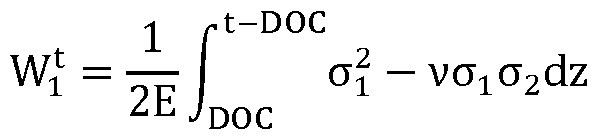 where: E is the Young’s modulus of a glass-based composition of the strengthened glass container;
Attorney Docket No.: SP23-321 is the Poisson’s ratio of the glass-based composition of the strengthened glass container; DOC is the depth of compression of surface compressive stress layers imparted via the strengthening; t is the local wall thickness of a wall of the strengthened glass container; is the stress in the tangential direction; is the stress in the hoop direction; and z is a direction normal to the outer surface of the strengthened glass container; a hoop tensile strain energy component (W ), wherein
 a frangibility ratio (W /G ), wherein W W + W = , G G where G is the critical energy release rate of the glass-based composition of the strengthened glass container, wherein G = (1 )K , E where K is the fracture toughness of the glass-based composition of the strengthened glass container, and wherein the frangibility ratio (W /G ) in the shoulder is greater than or equal to 3.2.