WO2025094281A1 - 設備監視システム、及び設備監視方法 - Google Patents
設備監視システム、及び設備監視方法 Download PDFInfo
- Publication number
- WO2025094281A1 WO2025094281A1 PCT/JP2023/039301 JP2023039301W WO2025094281A1 WO 2025094281 A1 WO2025094281 A1 WO 2025094281A1 JP 2023039301 W JP2023039301 W JP 2023039301W WO 2025094281 A1 WO2025094281 A1 WO 2025094281A1
- Authority
- WO
- WIPO (PCT)
- Prior art keywords
- power transmission
- span
- frequency
- measurement point
- facility
- Prior art date
- Legal status (The legal status is an assumption and is not a legal conclusion. Google has not performed a legal analysis and makes no representation as to the accuracy of the status listed.)
- Pending
Links
Images


Classifications
-
- G—PHYSICS
- G01—MEASURING; TESTING
- G01H—MEASUREMENT OF MECHANICAL VIBRATIONS OR ULTRASONIC, SONIC OR INFRASONIC WAVES
- G01H9/00—Measuring mechanical vibrations or ultrasonic, sonic or infrasonic waves by using radiation-sensitive means, e.g. optical means
-
- G—PHYSICS
- G01—MEASURING; TESTING
- G01V—GEOPHYSICS; GRAVITATIONAL MEASUREMENTS; DETECTING MASSES OR OBJECTS; TAGS
- G01V8/00—Prospecting or detecting by optical means
- G01V8/10—Detecting, e.g. by using light barriers
- G01V8/12—Detecting, e.g. by using light barriers using one transmitter and one receiver
- G01V8/16—Detecting, e.g. by using light barriers using one transmitter and one receiver using optical fibres
Definitions
- the present invention relates to an equipment monitoring system and an equipment monitoring method.
- Patent Document 1 describes an anomaly detection device that acquires backward Rayleigh scattered light from an OPGW (optical fiber composite overhead ground wire), generates vibration information for a frequency range including the natural frequency of the optical fiber composite overhead ground wire based on the acquired backward Rayleigh scattered light, and detects anomalies in power transmission equipment based on the generated vibration information.
- OPGW optical fiber composite overhead ground wire
- Patent document 2 describes how the distance in the line direction of the overhead power line from the imaging means to the moving object is calculated based on two-dimensional position data and the separation distance and focal length of each imaging means, and a danger zone is set on a plane that is approximately perpendicular to the overhead power line at the position of the moving object at the obtained distance, and an alarm is issued when the moving object enters this danger zone.
- JP 2023-50257 A Japanese Patent Application Publication No. 3-89103
- the present invention was made in consideration of this background, and aims to provide an equipment monitoring system and equipment monitoring method that can monitor the approach or contact of objects such as equipment to power transmission equipment and prevent accidents such as power outages.
- One of the means for solving the above problem is an equipment monitoring system that includes an optical analysis unit and an information processing device, and acquires the time change in vibration intensity for each frequency of the optical fiber at measurement points set along the optical fiber attached to the power transmission line using DAS (Distributed Acoustic Sensing), extracts the span having the measurement point where the time change in vibration intensity for each frequency includes an aspect caused by sound waves emitted from an object present in the vicinity of the measurement point as an object approach span, and generates information indicating the extracted object approach span.
- DAS Distributed Acoustic Sensing
- the present invention makes it possible to monitor the approach or contact of objects such as equipment to power transmission facilities, and to prevent accidents such as power outages.
- FIG. 1 is a diagram illustrating a schematic configuration of a facility monitoring system.
- FIG. 2 is a diagram illustrating a mechanism for measuring a vibration state by a DAS.
- FIG. 1 shows the trajectory of a patrol helicopter flying along a power line.
- 1 is a diagram showing an example of a change in vibration intensity over time for each frequency of an optical fiber.
- FIG. 1 is a diagram showing the main configuration of an equipment monitoring device.
- FIG. 2 is a diagram showing main functions of the equipment monitoring device.
- 13 is a flowchart illustrating an equipment monitoring process. 13 is an example of an object approach information presentation screen.
- FIG. 1 shows a schematic configuration of an equipment monitoring system 1 described as one embodiment of the present invention.
- the equipment monitoring system 1 includes an equipment monitoring device 100 provided in a substation 6 or the like, and a work schedule management device 300.
- the equipment monitoring device 100 is configured using an information processing device (computer).
- the equipment monitoring device 100 is communicatively connected to the work schedule management device 300 via a communication network (not shown).
- the communication network may be, for example, a LAN (Local Area Network), a WAN (Wide Area Network), the Internet, a PLC (Power Line Communication), a public communication network, a dedicated line, etc.
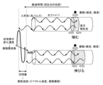
- the equipment monitoring device 100 uses the optical fiber 4a of the OPGW4 (OPTICAL fiber composite overhead ground wire) (optical fiber composite overhead ground wire) installed on the power transmission line 3 as a vibration detection sensor, and acquires the vibration state at each measurement point by a technology (distributed multipoint vibration measurement method (hereinafter referred to as "DAS" (Distributed Acoustic Sensing)) that measures the vibration state (vibration intensity, vibration frequency) based on the expansion and contraction of the optical fiber 4a at each of multiple measurement positions (hereinafter referred to as "measurement points") set along the optical fiber 4a.
- DAS distributed multipoint vibration measurement method
- the vibration state at each measurement point is acquired using the principle of a C-OTDR (Coherent detection Optical Time Domain Reflectometer).
- FIG. 2 is a diagram explaining the mechanism by which the equipment monitoring device 100 measures the vibration state at each measurement point using DAS.
- the equipment monitoring device 100 inputs a light pulse (laser pulse, hereinafter also referred to as "incident light") from the end face of the optical fiber 4a, and measures the change speed ( ⁇ stretching frequency) of the phase difference of the backscattered light of the light pulse at each measurement point.
- the phase difference is estimated from the intensity change due to the interference between the backscattered lights.
- the equipment monitoring device 100 determines the vibration frequency (for example, vibration frequency in the range of up to 10 kHz) of the longitudinal wave and transverse wave of the optical fiber 4a at each measurement point based on the measured change speed.
- the vibration frequency for example, vibration frequency in the range of up to 10 kHz
- the equipment monitoring device 100 also determines the vibration intensity (spectral intensity, vibration amplitude) at each measurement point based on the phase difference for each vibration frequency.
- the equipment monitoring device 100 also determines the position of each measurement point (distance from the end face) based on the elapsed time from the time when the incident light is input to the end face to the time when the return light is received.
- the above measurement points are set, for example, at predetermined intervals d (m) along the optical fiber that are shorter than the span of the transmission tower 2 (0 (m), d (m), ..., N (m), N + d (m), N + 2 d (m)).
- predetermined interval d is 5 (m) and measurement points are set over a maximum range of 70 (km) of the transmission line 3, approximately 14,000 measurement points will be set along the optical fiber.
- the vibration state at each measurement point includes a vibration state caused by sound waves emitted from objects located near the power transmission equipment (power transmission tower 2, power transmission line 3, substation 6, etc.).
- the equipment monitoring device 100 acquires information about objects located near the power transmission equipment based on the vibration state at each measurement point.
- the work schedule management device 300 manages information about the schedule of work to be performed in the vicinity of the power transmission equipment (hereinafter referred to as "work schedule 311") in a database.
- Work to be managed includes, for example, patrols and inspections of the power transmission equipment, replacement and expansion work of the power transmission equipment, and various work performed in the vicinity of the power transmission equipment (including work unrelated to the power transmission equipment).
- the work schedule management device 300 provides the contents of the work schedule 311 to the equipment monitoring device 100.
- the work schedule 311 is registered in and managed in the database, for example, by the manager of the power transmission equipment.
- Figure 3A shows an example of the flight trajectory of a patrol helicopter flying along a power line 3 for patrol inspection work.
- the figure shows on a map the flight path (flight trajectory) of a patrol helicopter flying along power transmission towers 2 with identifiers (hereinafter referred to as "tower IDs") of "58" to "68.”
- Figure 3B is a graph showing the time change for each frequency in the vibration state of each measurement point, acquired by the equipment monitoring device 100 using the DAS when the patrol helicopter flew along the route shown in Figure 3A.
- Each of the three graphs shows the time change in vibration intensity for each frequency of the optical fiber 4a, measured at a specific measurement point for each span with an identifier (hereinafter referred to as "span ID") of "61_62", “62_63”, and "63_64".
- span ID an identifier
- time flows from top to bottom on the page.
- the shade of color in this figure represents the vibration intensity (arbitrary unit) for each frequency (the lighter the color, the greater the vibration intensity).
- the time-dependent change in vibration intensity for each frequency at each measurement point obtained by the DAS exhibits a pattern caused by sound waves emitted from objects such as equipment located near each measurement point. Based on the above-mentioned pattern in the time-dependent change in vibration intensity for each frequency at each observed measurement point, it is possible to identify spans where objects are present nearby (hereinafter referred to as "object approach spans").
- the change over time in vibration intensity for each frequency at each measurement point obtained by the DAS shows behavior that is caused by an object coming into contact with the power transmission equipment near each measurement point. Therefore, based on the above behavior in the change over time in vibration intensity for each frequency at each observed measurement point, it is possible to determine whether an object is coming into contact with the power transmission equipment.
- the equipment monitoring device 100 acquires information about objects present in the vicinity of the power transmission equipment based on the time-dependent changes in vibration state for each frequency acquired at the measurement points of each span, and provides the acquired information to the manager of the power transmission equipment.
- FIG. 4A is a diagram showing the main configuration of the equipment monitoring device 100.
- the equipment monitoring device 100 comprises a processor 101, a main memory device 102 (memory), an auxiliary memory device 103 (external memory device), an input device 104, an output device 105, a communication device 106, and an optical analysis unit 107. These are connected so as to be able to communicate via a bus, a communication cable, or the like.
- all or a part of the equipment monitoring device 100 may be realized using virtual information processing resources, such as a virtual server provided by a cloud system, for example.
- the processor 101 is configured using, for example, a CPU (Central Processing Unit), an MPU (Micro Processing Unit), a GPU (Graphics Processing Unit), an FPGA (Field Programmable Gate Array), an ASIC (Application Specific Integrated Circuit), an AI (Artificial Intelligence) chip, etc.
- a CPU Central Processing Unit
- MPU Micro Processing Unit
- GPU Graphics Processing Unit
- FPGA Field Programmable Gate Array
- ASIC Application Specific Integrated Circuit
- AI Artificial Intelligence
- the main memory device 102 is a memory device used by the processor 101 when executing a program, and is, for example, ROM (Read Only Memory), RAM (Random Access Memory), non-volatile memory (NVRAM (Non Volatile RAM)), etc.
- ROM Read Only Memory
- RAM Random Access Memory
- NVRAM Non Volatile RAM
- the auxiliary storage device 103 is a device that stores programs and data, and can be configured, for example, with an SSD (Solid State Drive), a hard disk drive, an optical storage device (CD (Compact Disc), DVD (Digital Versatile Disc), etc.). Programs and data can be read into the auxiliary storage device 103 from other information processing devices equipped with non-transient recording media or non-transient storage devices via a recording medium reading device or communication device 106. The programs and data stored (memorized) in the auxiliary storage device 103 are read into the main storage device 102 as needed.
- SSD Solid State Drive
- CD Compact Disc
- DVD Digital Versatile Disc
- the input device 104 is an interface that accepts information input from the outside, such as a keyboard, a mouse, a touch panel, or a voice input device.
- the output device 105 is an interface that outputs various information such as the progress of processing and the results of processing to the outside.
- the output device 105 is, for example, a display device (liquid crystal monitor, LCD (Liquid Crystal Display) etc.) that visualizes the various information described above, a device that converts the various information described above into audio (audio output device (speaker etc.)), or a device that converts the various information described above into text (printing device etc.).
- the information processing device 10 may be configured to input and output information between it and other devices via the communication device 106.
- the input device 104 and the output device 105 constitute a user interface that realizes interactive processing with the user (accepting information, providing information, etc.).
- the communication device 106 is a device that realizes communication with other devices via a communication network (such as a LAN (Local Area Network), WAN (Wide Area Network), the Internet, a public communication network, a dedicated line, etc.).
- the communication device 106 is a wired or wireless communication interface that realizes communication with other devices via a communication medium, such as a NIC (Network Interface Card), a wireless communication module, or a USB module (USB: Universal Serial Bus), etc.
- the optical analysis unit 107 is a device that uses a DAS to measure the vibration state of a measurement point, and includes a vibration measurement device using a C-OTDR and a signal processing circuit.
- the optical analysis unit 107 includes a CW (continuous wave) laser light source that generates an optical pulse (laser light) to be input to the end face of the optical fiber 4a, an optical pulse generator, an optical amplifier, optical equipment (optical detector, optical interferometer), a signal processing circuit (phase calculation circuit, etc.), etc.
- the optical analysis unit 107 and the optical fiber 4a are connected, for example, by optically connecting the output part of the laser light source of the optical analysis unit 107 to the connection port (socket) of the core wire of the OPGW installed in the substation. Therefore, the connection does not cause any impact on the power system, such as a power outage.
- the equipment monitoring device 100 may be equipped with, for example, an operating system, a file system, a DBMS (DataBase Management System) (relational database, NoSQL, etc.), a KVS (Key-Value Store), etc.
- an operating system e.g., an operating system, a file system, a DBMS (DataBase Management System) (relational database, NoSQL, etc.), a KVS (Key-Value Store), etc.
- DBMS DataBase Management System
- NoSQL NoSQL, etc.
- KVS Key-Value Store
- the various functions of the equipment monitoring device 100 are realized by the processor 101 reading and executing programs stored in the main memory device 102, or by the hardware (FPGA, ASIC, AI chip, etc.) that constitutes the equipment monitoring device 100.
- the equipment monitoring device 100 stores various information (data), for example, as tables in a database or files managed by a file system.
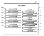
- FIG. 4B is a block diagram explaining the main functions of the equipment monitoring device 100.
- the equipment monitoring device 100 has the following functions: a memory unit 110, a vibration state measurement unit 120, an object approach span identification unit 125, a work schedule presence/absence determination unit 130, a confirmation instruction generation unit 132, a contact presence/absence determination unit 135, an equipment abnormality presence/absence determination unit 140, a response information generation unit 145, and an object approach information presentation unit 150.
- the memory unit 110 stores the vibration state for each measurement point 111, the object approach span 112, the work schedule 113, the confirmation instruction 114, the contact presence/absence determination result 115, the equipment abnormality presence/absence determination result 116, the response information 117, and the power transmission equipment information 118.
- the vibration state measurement unit 120 uses the DAS to measure the time change (time series data) of the vibration state (vibration intensity, vibration frequency) at each measurement point on each span, and manages the measurement results as the vibration state for each measurement point 111.
- the vibration state for each measurement point 111 includes, for example, the information shown in each graph in Figure 3B.
- the object approaching span identification unit 125 identifies an object approaching span based on the change over time in vibration intensity for each frequency during the above-mentioned period at each measurement point managed in the vibration state for each measurement point 111. For example, when vibration intensity equal to or greater than a preset threshold is observed at the same frequency during the same time period at each measurement point of multiple adjacent spans, the object approaching span identification unit 125 identifies these spans as object approaching spans. The object approaching span identification unit 125 manages the span IDs of the identified object approaching spans as object approaching spans 112.
- the work schedule determination unit 130 acquires the work schedule 311 for the period during which vibration intensity equal to or greater than the threshold value is observed in the object approach span from the work schedule management device 300, and determines whether or not there is work scheduled to be performed in the object approach span during the period (whether or not advance information about the work has been acquired).
- the confirmation instruction generation unit 132 When the work plan existence determination unit 130 determines that there is no work scheduled to be performed in the object approach span during the above-mentioned period (preliminary information has not been acquired), the confirmation instruction generation unit 132 generates a confirmation instruction including information indicating that confirmation is required from the on-site worker, and manages the generated confirmation instruction as a confirmation instruction 114 by associating it with the span ID of the object approach span.
- the contact determination unit 135 determines whether or not an object has come into contact with the power transmission equipment based on the change over time in vibration intensity for each frequency at the measurement point of the object approach span during the above-mentioned period, and manages the determination result as the contact determination result 115 in association with the span ID. For example, the contact determination unit 135 determines that an object has come into contact with the power transmission equipment when multiple vibration intensities equal to or greater than a preset threshold are observed at the same time at the measurement points of spans adjacent to the object approach span.
- the equipment abnormality determination unit 140 determines whether or not an abnormality (such as a broken wire or partial deformation) has occurred in the power transmission equipment, and manages the determination result in the equipment abnormality determination result 116. For example, the equipment abnormality determination unit 140 determines whether or not an abnormality has occurred in the power transmission equipment in the object approach span by comparing the natural frequency of the optical fiber 4a understood from the vibration intensity for each frequency at the measurement point in the object approach span after the object has contacted with the natural frequency of the optical fiber 4a understood from the vibration intensity for each frequency in the object approach span in normal times (before the object has contacted) that have been stored in advance. For example, the equipment abnormality determination unit 140 determines that an abnormality has occurred in the power transmission equipment in the object approach span when a natural frequency different from the natural frequency in normal times is observed a predetermined number or more.
- an abnormality such as a broken wire or partial deformation
- the correspondence information generating unit 145 generates information indicating the object approach span with which the object came into contact and information indicating the action that the administrator should take for the object approach span (the power transmission equipment of the object approach span) (hereinafter referred to as "correspondence information"), and manages the generated correspondence information as correspondence information 117.
- the correspondence information generating unit 145 manages the correspondence information in correspondence with the span ID in the power transmission equipment information 118, and generates the correspondence information by comparing the span ID of the object approach span with the power transmission equipment information 118.
- the power transmission equipment information 118 includes, in addition to the correspondence information, information on the tower ID and the power transmission equipment associated with the span ID (such as the position of the power transmission tower 2, information on the power transmission equipment installed in the power transmission tower 2 and its surroundings), and the correspondence information generating unit 145 adds this information to the correspondence information as necessary.
- the object approaching information presentation unit 150 presents the contents of the confirmation instruction 114 and the contents of the response information 117 to the manager.
- the object approaching information presentation unit 150 generates a screen (object approaching information presentation screen 600 described later) that lists, for example, the contents of the object approaching span 112, the contents of the work schedule 113, the contents of the confirmation instruction 114, the contents of the contact presence/absence determination result 115, the contents of the response information 117, and the like, and presents it to the manager.
- FIG. 5 is a flowchart explaining the processing performed by the equipment monitoring device 100 (hereinafter referred to as "equipment monitoring processing S500").
- equipment monitoring processing S500 will be explained with reference to the same figure. Note that, as a premise for the following explanation, it is assumed that the work scheduled to be performed on each span has already been registered in the work schedule management device 300. Furthermore, it is assumed that the vibration state measurement unit 120 of the equipment monitoring device 100 measures the time change in the vibration state (vibration intensity, vibration frequency) of each measurement point on each span in real time using DAS, and manages the latest vibration state of each measurement point as the vibration state for each measurement point 111.
- vibration state measurement unit 120 of the equipment monitoring device 100 measures the time change in the vibration state (vibration intensity, vibration frequency) of each measurement point on each span in real time using DAS, and manages the latest vibration state of each measurement point as the vibration state for each measurement point 111.
- the object approaching span identification unit 125 monitors the vibration state 111 for each measurement point in real time (S511 to S512: No). When the object approaching span identification unit 125 identifies an object presence span (S512: Yes), it manages the identified object presence span as an object approaching span 112 (S513).
- the work schedule determination unit 130 acquires the work schedule for the above-mentioned period in the object approach span from the work schedule management device 300, and determines whether or not there is work scheduled for the above-mentioned period in the object approach span (whether or not advance information has been acquired) (S514). If there is no work scheduled for the above-mentioned period (S514: No), the process proceeds to S515. If there is work scheduled for the above-mentioned period (S514: Yes), the process proceeds to S519.
- the confirmation instruction generation unit 132 generates information indicating that on-site confirmation is required and manages it as a confirmation instruction 114.
- the contact determination unit 135 determines whether the object has come into contact with the power transmission equipment based on the state of the change over time in vibration intensity for each frequency at the measurement point in the object approach span during the above-mentioned period, and manages the determination result as the contact determination result 115 (S516). If the contact determination unit 135 determines that the object has come into contact with the power transmission equipment (S516: Yes), the process proceeds to S517. If the contact determination unit 135 determines that the object has not come into contact with the power transmission equipment (S516: No), the process returns to S519.
- the equipment abnormality determination unit 140 determines whether or not an abnormality has occurred in the power transmission equipment in the object approach span. If the equipment abnormality determination unit 140 determines that an abnormality has occurred in the power transmission equipment in the object approach span (S517: Yes), the determination result is managed as the equipment abnormality determination result 116, and processing proceeds to S518. On the other hand, if the equipment abnormality determination unit 140 determines that no abnormality has occurred in the power transmission equipment in the object approach span (S517: No), processing proceeds to S519.
- the correspondence information generation unit 145 generates correspondence information for the object approach span in which it is determined that an abnormality has occurred, and manages the generated correspondence information as correspondence information 117.
- the object approaching information presentation unit 150 generates a screen that presents information about the approaching object (hereinafter referred to as the "object approaching information presentation screen 600") and presents the generated object approaching information presentation screen 600 to the administrator.
- FIG. 6 shows an example of an object approach information display screen 600.
- the example object approach information presentation screen 600 has a display field 611 for the observation date and time, a display field 612 for the object approach span, a display field 613 for the work schedule and confirmation instructions, a display field 614 for whether or not there is contact, and a display field 615 for corresponding information.
- the observation date and time display field 611 displays the date and time when the object approach span identification unit 125 identified the object approach span.
- the object approach span display field 612 displays the span ID (contents of object approach span 112) of the object approach span identified by the object approach span identification unit 125.
- the work schedule and confirmation instruction display field 613 displays the contents of the work schedule 311 for the above-mentioned period of the object approach span acquired by the work schedule presence/absence determination unit 130, and the contents of the confirmation instruction 114 generated by the confirmation instruction generation unit 132.
- the contact presence/absence display field 614 displays the result of the judgment made by the contact presence/absence determination unit 135 (contents of the contact presence/absence determination result 115).
- the contents of the correspondence information 117 are displayed in the correspondence information display field 615.
- the manager can quickly check information about the span where the object is approaching (span ID, whether work is scheduled, whether the object is in contact with the power transmission equipment, etc.), whether any action is required, and what action should be taken, and can take the necessary action efficiently and quickly.
- information regarding an object approaching the power transmission facility can be obtained remotely and quickly based on information obtained using the DAS, and provided to the manager of the power transmission facility. Therefore, based on the information provided, the manager can quickly grasp that an object has approached the power transmission facility and the impact that the object has had on the power transmission facility, and can efficiently monitor the approach or contact of an object with the power transmission facility to prevent accidents such as power outages.
- the object approach information presentation unit 150 may receive a span (span ID) designation from the user, and present at least one of the object approach span 112, work schedule 113, confirmation instruction 114, contact presence/absence determination result 115, equipment abnormality presence/absence determination result 116, and corresponding information 117, which correspond to the received span.
- a span span ID
- the object approach information presentation unit 150 may receive a span (span ID) designation from the user, and present at least one of the object approach span 112, work schedule 113, confirmation instruction 114, contact presence/absence determination result 115, equipment abnormality presence/absence determination result 116, and corresponding information 117, which correspond to the received span.
- the extraction of the object approach span by the object approach span identification unit 125 and the determination of whether or not the object is in contact with the power transmission equipment by the contact determination unit 135 may be performed using a machine learning model that has been trained to output the determination result of the object approach span or the object's contact with the power transmission equipment as the objective variable when feature quantities extracted by performing image recognition processing on the graph (image) shown in Figure 3B are input as explanatory variables.
- information on the surrounding environment of the location where the object is located may be acquired, and the type of object may be identified by taking this information into consideration. For example, if the surrounding environment of the location where the object is located is a residential area, it may be estimated that the object is likely to be heavy machinery.
- the change over time in vibration intensity for each frequency at a measurement point shows a characteristic pattern for each type of object. Therefore, based on the change over time in vibration intensity for each frequency at each observed measurement point, the type of object present near each measurement point may be identified, and the identified type of object may be presented.
- Equipment monitoring system 2 Transmission tower 3 Transmission line 4 OPGW 4a Optical fiber 100 Equipment monitoring device 107
- Optical analysis unit 110 Memory unit 111 Vibration state for each measurement point 112 Object approaching span 113 Work schedule 114 Confirmation instruction 115 Contact presence/absence determination result 116 Equipment abnormality presence/absence determination result 117 Correspondence information 118 Power transmission equipment information 120 Vibration state measurement unit 125 Object approaching span identification unit 130 Work schedule presence/absence determination unit 132 Confirmation instruction generation unit 135 Contact presence/absence determination unit 140 Equipment abnormality presence/absence determination unit 145 Correspondence information generation unit 150 Object approaching information presentation unit S500 Equipment monitoring process 600 Object approaching information presentation screen
Landscapes
- Physics & Mathematics (AREA)
- General Physics & Mathematics (AREA)
- Life Sciences & Earth Sciences (AREA)
- General Life Sciences & Earth Sciences (AREA)
- Geophysics (AREA)
- Measurement Of Mechanical Vibrations Or Ultrasonic Waves (AREA)
- Geophysics And Detection Of Objects (AREA)
Priority Applications (2)
| Application Number | Priority Date | Filing Date | Title |
|---|---|---|---|
| PCT/JP2023/039301 WO2025094281A1 (ja) | 2023-10-31 | 2023-10-31 | 設備監視システム、及び設備監視方法 |
| JP2024504538A JP7525082B1 (ja) | 2023-10-31 | 2023-10-31 | 設備監視システム、及び設備監視方法 |
Applications Claiming Priority (1)
| Application Number | Priority Date | Filing Date | Title |
|---|---|---|---|
| PCT/JP2023/039301 WO2025094281A1 (ja) | 2023-10-31 | 2023-10-31 | 設備監視システム、及び設備監視方法 |
Publications (1)
| Publication Number | Publication Date |
|---|---|
| WO2025094281A1 true WO2025094281A1 (ja) | 2025-05-08 |
Family
ID=91967703
Family Applications (1)
| Application Number | Title | Priority Date | Filing Date |
|---|---|---|---|
| PCT/JP2023/039301 Pending WO2025094281A1 (ja) | 2023-10-31 | 2023-10-31 | 設備監視システム、及び設備監視方法 |
Country Status (2)
| Country | Link |
|---|---|
| JP (1) | JP7525082B1 (https=) |
| WO (1) | WO2025094281A1 (https=) |
Citations (10)
| Publication number | Priority date | Publication date | Assignee | Title |
|---|---|---|---|---|
| JPH05180690A (ja) * | 1991-12-27 | 1993-07-23 | Sumitomo Electric Ind Ltd | 電力ケーブルの外傷予知方法 |
| JPH07280639A (ja) * | 1994-04-11 | 1995-10-27 | Sumitomo Electric Ind Ltd | 送電設備の音響分析による設備異常診断システム |
| JP2002152937A (ja) * | 2000-11-13 | 2002-05-24 | Toshiba Corp | 異常信号監視装置 |
| WO2022004626A1 (ja) * | 2020-06-29 | 2022-01-06 | 日本電気株式会社 | 長尺インフラストラクチャの保護監視システム、保護監視装置、保護監視方法及び保護監視プログラムを記憶する記憶媒体 |
| JP2022507455A (ja) * | 2018-11-13 | 2022-01-18 | ファイバー センス ピーティーワイ リミテッド | 分散型光ファイバセンシングのための方法及びシステム |
| WO2022045117A1 (ja) * | 2020-08-25 | 2022-03-03 | 日本電気株式会社 | 障害予測システム、障害予測装置及び障害予測方法 |
| JP7235115B2 (ja) * | 2019-07-17 | 2023-03-08 | 日本電気株式会社 | 光ファイバセンシングシステム、光ファイバセンシング機器、及び異常判断方法 |
| JP2023050257A (ja) * | 2021-09-30 | 2023-04-11 | 富士通株式会社 | 異常検出プログラム、異常検出装置、及び異常検出方法 |
| JP2023078151A (ja) * | 2017-07-18 | 2023-06-06 | ファイバー センス リミテッド | 海洋環境における分散音響センシングの方法及びシステム |
| JP2023538196A (ja) * | 2020-08-25 | 2023-09-07 | エヌイーシー ラボラトリーズ アメリカ インク | 都市規模の音響インパルスの検出と位置特定 |
Family Cites Families (2)
| Publication number | Priority date | Publication date | Assignee | Title |
|---|---|---|---|---|
| WO2021029186A1 (ja) * | 2019-08-13 | 2021-02-18 | 日本電気株式会社 | 光ファイバセンシングシステム、光ファイバセンシング機器、及び停電検出方法 |
| WO2021059477A1 (ja) * | 2019-09-27 | 2021-04-01 | 日本電気株式会社 | 光ファイバセンシングシステム、監視方法、及び非一時的なコンピュータ可読媒体 |
-
2023
- 2023-10-31 JP JP2024504538A patent/JP7525082B1/ja active Active
- 2023-10-31 WO PCT/JP2023/039301 patent/WO2025094281A1/ja active Pending
Patent Citations (10)
| Publication number | Priority date | Publication date | Assignee | Title |
|---|---|---|---|---|
| JPH05180690A (ja) * | 1991-12-27 | 1993-07-23 | Sumitomo Electric Ind Ltd | 電力ケーブルの外傷予知方法 |
| JPH07280639A (ja) * | 1994-04-11 | 1995-10-27 | Sumitomo Electric Ind Ltd | 送電設備の音響分析による設備異常診断システム |
| JP2002152937A (ja) * | 2000-11-13 | 2002-05-24 | Toshiba Corp | 異常信号監視装置 |
| JP2023078151A (ja) * | 2017-07-18 | 2023-06-06 | ファイバー センス リミテッド | 海洋環境における分散音響センシングの方法及びシステム |
| JP2022507455A (ja) * | 2018-11-13 | 2022-01-18 | ファイバー センス ピーティーワイ リミテッド | 分散型光ファイバセンシングのための方法及びシステム |
| JP7235115B2 (ja) * | 2019-07-17 | 2023-03-08 | 日本電気株式会社 | 光ファイバセンシングシステム、光ファイバセンシング機器、及び異常判断方法 |
| WO2022004626A1 (ja) * | 2020-06-29 | 2022-01-06 | 日本電気株式会社 | 長尺インフラストラクチャの保護監視システム、保護監視装置、保護監視方法及び保護監視プログラムを記憶する記憶媒体 |
| WO2022045117A1 (ja) * | 2020-08-25 | 2022-03-03 | 日本電気株式会社 | 障害予測システム、障害予測装置及び障害予測方法 |
| JP2023538196A (ja) * | 2020-08-25 | 2023-09-07 | エヌイーシー ラボラトリーズ アメリカ インク | 都市規模の音響インパルスの検出と位置特定 |
| JP2023050257A (ja) * | 2021-09-30 | 2023-04-11 | 富士通株式会社 | 異常検出プログラム、異常検出装置、及び異常検出方法 |
Also Published As
| Publication number | Publication date |
|---|---|
| JPWO2025094281A1 (https=) | 2025-05-08 |
| JP7525082B1 (ja) | 2024-07-30 |
Similar Documents
| Publication | Publication Date | Title |
|---|---|---|
| Fouda et al. | Pattern recognition of optical fiber vibration signal of the submarine cable for its safety | |
| KR102301201B1 (ko) | IoT 센서 기반 회전 기기의 정밀 상태 진단 장치 및 방법 | |
| CN113467433A (zh) | 一种机械设备故障检测的方法及装置 | |
| CN116186642B (zh) | 一种基于多维特征融合的分布式光纤传感事件预警方法 | |
| CN114613116B (zh) | 防外破预警方法、装置、设备及存储介质 | |
| JP2023109769A (ja) | 学習装置、異常兆候検知装置、異常兆候検知システム、学習方法およびプログラム | |
| JP7630642B2 (ja) | 分散型光ファイバセンシングを用いた配電変圧器の位置特定と監視 | |
| CN118568159A (zh) | 一种盐穴储气库的风险预警可视化系统 | |
| CN107255677A (zh) | 一种基于压电智能传感器的大坝安全损伤监测系统 | |
| JP7525082B1 (ja) | 設備監視システム、及び設備監視方法 | |
| CN120592821B (zh) | 基于多模态数据的风机健康状态检测方法、装置、设备及介质 | |
| CN109019349A (zh) | 故障检测方法、检测器、计算机存储介质及起重机 | |
| CN116576957A (zh) | 光缆外破预警界面的显示方法、装置、设备及存储介质 | |
| JP7474937B1 (ja) | 落雷監視システム、及び落雷監視方法 | |
| CN120658767A (zh) | 基于边缘计算的景区文物古迹智能保护与监测系统 | |
| JP7464206B1 (ja) | 設備監視システム、及び設備監視方法 | |
| CN119691599A (zh) | 一种应用于地铁故障的智能运维方法、装置及电子设备 | |
| CN118529094A (zh) | 一种轨道监测方法、设备、介质和产品 | |
| JP7845110B2 (ja) | 電力設備の監視システム、及び監視方法 | |
| KR102195266B1 (ko) | 음향신호를 이용한 플랜트 설비의 결함 진단 방법 | |
| WO2025109652A1 (ja) | 設備監視システム、及び設備監視方法 | |
| Nanadic et al. | Comparative study of vibration condition indicators for detecting cracks in spur gears | |
| JP7460042B1 (ja) | 災害発生予測システム、及び災害発生予測方法 | |
| Wen et al. | Research on Dynamic Monitoring of Train Running Part Using Integrated Detection System | |
| Bodnar et al. | A case study of the use of statistical processing of the armature rotation irregularities for the diagnostics of locomotive traction electric motors |
Legal Events
| Date | Code | Title | Description |
|---|---|---|---|
| ENP | Entry into the national phase |
Ref document number: 2024504538 Country of ref document: JP Kind code of ref document: A |
|
| WWE | Wipo information: entry into national phase |
Ref document number: 2024504538 Country of ref document: JP |
|
| 121 | Ep: the epo has been informed by wipo that ep was designated in this application |
Ref document number: 23957609 Country of ref document: EP Kind code of ref document: A1 |