WO2025089222A1 - バルブ装置および緩衝器 - Google Patents
バルブ装置および緩衝器 Download PDFInfo
- Publication number
- WO2025089222A1 WO2025089222A1 PCT/JP2024/037369 JP2024037369W WO2025089222A1 WO 2025089222 A1 WO2025089222 A1 WO 2025089222A1 JP 2024037369 W JP2024037369 W JP 2024037369W WO 2025089222 A1 WO2025089222 A1 WO 2025089222A1
- Authority
- WO
- WIPO (PCT)
- Prior art keywords
- control rod
- plunger
- valve
- movable part
- housing
- Prior art date
- Legal status (The legal status is an assumption and is not a legal conclusion. Google has not performed a legal analysis and makes no representation as to the accuracy of the status listed.)
- Pending
Links
Images


Classifications
-
- F—MECHANICAL ENGINEERING; LIGHTING; HEATING; WEAPONS; BLASTING
- F16—ENGINEERING ELEMENTS AND UNITS; GENERAL MEASURES FOR PRODUCING AND MAINTAINING EFFECTIVE FUNCTIONING OF MACHINES OR INSTALLATIONS; THERMAL INSULATION IN GENERAL
- F16F—SPRINGS; SHOCK-ABSORBERS; MEANS FOR DAMPING VIBRATION
- F16F9/00—Springs, vibration-dampers, shock-absorbers, or similarly-constructed movement-dampers using a fluid or the equivalent as damping medium
- F16F9/32—Details
- F16F9/34—Special valve constructions; Shape or construction of throttling passages
-
- F—MECHANICAL ENGINEERING; LIGHTING; HEATING; WEAPONS; BLASTING
- F16—ENGINEERING ELEMENTS AND UNITS; GENERAL MEASURES FOR PRODUCING AND MAINTAINING EFFECTIVE FUNCTIONING OF MACHINES OR INSTALLATIONS; THERMAL INSULATION IN GENERAL
- F16F—SPRINGS; SHOCK-ABSORBERS; MEANS FOR DAMPING VIBRATION
- F16F9/00—Springs, vibration-dampers, shock-absorbers, or similarly-constructed movement-dampers using a fluid or the equivalent as damping medium
- F16F9/32—Details
- F16F9/44—Means on or in the damper for manual or non-automatic adjustment; such means combined with temperature correction
Definitions
- the present invention relates to a valve device and a shock absorber.
- Shock absorbers are used, for example, by being interposed between the body and wheels of a vehicle, and suppress vibrations between the body and wheels by the damping force generated when the shock absorbers expand and contract.
- such a shock absorber is configured with a cylinder, a piston movably inserted into the cylinder to divide the cylinder into an extension side chamber and a compression side chamber filled with hydraulic oil, a piston rod movably inserted into the cylinder and connected to the piston, a tank for storing hydraulic oil, an extension side leaf valve provided on the piston to allow the hydraulic oil to flow with resistance from the extension side chamber to the compression side chamber, a compression side leaf valve provided on the piston to resist the flow of hydraulic oil from the compression side chamber to the extension side chamber, a bypass passage connecting the extension side chamber and the compression side chamber via the piston rod, and a valve device provided in the bypass passage to resist the flow of hydraulic oil passing through the bypass passage.
- the valve device is equipped with a control rod that is inserted axially movably into a cylindrical piston rod, a cylindrical valve seat that is fixed inside the piston rod and installed in the bypass passage, a needle that adjusts the flow area in the bypass passage by moving away from and toward the valve seat within the piston rod depending on the displacement of the control rod, and an adjuster that is screwed into a hole in a vehicle mounting bracket provided at the tip of the piston rod and has its tip abutting the control rod.
- the adjuster is cylindrical and has a conical contact portion at its tip that contacts the tip of the control rod, a threaded portion on the outer periphery of the base end, and a groove at the base end for inserting a tool. It is screwed into a threaded hole that opens from the side of the bracket and faces the opening at the top end of the piston rod.
- the adjuster By using a tool to rotate the adjuster, the adjuster can be moved axially back and forth within the threaded hole.
- the conical abutment portion pushes the control rod into the piston rod, so that the control rod moves in a direction that inserts into the piston rod, shortening the distance between the needle and the valve seat and reducing the flow path area in the valve.
- the abutment portion retracts and the pressure inside the piston rod that the needle receives presses the control rod in a direction that moves out of the piston rod, so that the control rod moves in a direction that removes it from within the piston rod, moving the needle away from the valve seat and increasing the flow path area in the valve.
- the shock absorber user can manually operate an adjuster to adjust the degree to which the valve opens, thereby adjusting the damping force generated by the shock absorber.
- a shock absorber is used by being installed between the body of a vehicle and the rear wheel, increasing the damping force when the vehicle starts can suppress sinking of the body on the rear wheel side, increasing the ground load of the rear wheel and improving traction, but after starting, the damping force becomes excessive and it is preferable to reduce the damping force. Also, if the damping force is increased while a saddle-type vehicle is stopped, it is possible to suppress the up and down movement of the body when riding and stabilize the body posture when riding, but it is better to reduce the damping force when driving.
- the present invention aims to provide a valve device and shock absorber that can temporarily increase damping force and is inexpensive.
- the valve device of the present invention is equipped with a valve that has a movable part that is capable of reciprocating motion and is biased to one side by the pressure in the flow path, and that increases the flow resistance in the flow path when the movable part is displaced to the other side, and a temporary fixing device that can temporarily fix the movable part and releases the temporary fixation of the movable part when the force biasing the movable part to one side reaches or exceeds a predetermined value.
- the damping force can be temporarily increased by temporarily fixing the movable part in a position where the valve increases the flow path resistance, and the damping force can be decreased when the temporary fixation of the movable part is released by the action of pressure in the flow path.
- the shock absorber of the present invention comprises a cylinder, a cylindrical piston rod inserted into the cylinder so as to be axially movable, a piston connected to the tip end of the piston rod and inserted into the cylinder so as to be axially movable, and dividing the inside of the cylinder into an extension side chamber and a compression side chamber, a damping passage communicating between the extension side chamber and the compression side chamber, a control rod housed within the piston rod so as to be axially movable, and biased towards the base end of the piston rod by the pressure within the damping passage, a valve which increases the flow resistance in the damping passage when the control rod is displaced towards the tip end of the piston rod, and a valve capable of temporarily fixing the control rod and biasing the control rod towards the base end.
- the temporary fixing device releases the temporary fixation of the control rod when the force exerted by the temporary fixing device exceeds a predetermined value.
- the temporary fixing device has a bracket attached to the base end of the piston rod, a housing hole that opens from the outside and faces one end of the control rod, and allows the device to be attached to a vehicle, and a plunger that is housed in the housing hole and can move relative to the bracket and abut against one end of the control rod to displace the control rod, and temporarily fixes the control rod by restricting the relative movement of the plunger with respect to the bracket, and a stopper that is inserted into the housing hole and can change its position, and that stops the plunger from retracting toward the opening side from the housing hole when it abuts against the plunger.
- the shock absorber configured in this way, the damping force can be temporarily increased by temporarily fixing the control rod at a position where the needle valve increases the flow resistance, and the damping force can be decreased when the temporary fixing of the control rod is released by the action of pressure in the damping passage.
- the shock absorber can temporarily increase the damping force and then decrease it, and since an actuator such as a motor is not required to increase the damping force, the cost is also low.
- the shock absorber is applied to a saddle-type vehicle, the damping force can be temporarily increased while the vehicle is stopped, and the sinking of the vehicle body when the user gets on the saddle-type vehicle can be suppressed, the vehicle body posture can be stabilized when the user is on the vehicle, and the damping force can be decreased while the vehicle is moving, improving the ride comfort of the vehicle.
- the plunger and the stopper are accommodated in an accommodation hole provided in a bracket provided at the base end of the piston rod, and the stopper can be rotated from the outside without interference from the suspension spring, so that the control rod can be easily temporarily fixed, and the burden on the user is reduced.
- FIG. 1 is a cross-sectional view of a shock absorber according to one embodiment.
- FIG. 2 is a diagram showing a shock absorber attached to a saddle-type vehicle.
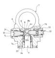
- FIG. 3 is a partially enlarged cross-sectional view of the shock absorber according to the embodiment.
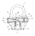
- FIG. 4 is an enlarged cross-sectional view of the temporary fixing device in a state where the stopper is operated to push the movable part toward the other side with the plunger.
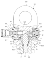
- FIG. 5 is an enlarged cross-sectional view of the temporary fixing device in a state in which the movable portion is temporarily fixed by the plunger.
- FIG. 6 is a diagram showing a first modified example of the temporary fixing device.
- FIG. 7 is a diagram showing a second modified example of the temporary fixing device.
- FIG. 8 is a diagram showing a third modified example of the temporary fixing device in a state in which the movable portion is temporarily fixed.
- FIG. 9 is a diagram showing a third modified example of the temporary fixing device in a state in which the movable portion has been moved to one side.
- a shock absorber D equipped with a valve device V in one embodiment includes a cylinder 1, a cylindrical piston rod 2 inserted into the cylinder 1 so as to be movable in the axial direction, a piston 3 connected to the tip end of the piston rod 2 and inserted into the cylinder 1 so as to be movable in the axial direction and which divides the inside of the cylinder 1 into an extension side chamber R1 and a compression side chamber R2, a damping passage P which communicates between the extension side chamber R1 and the compression side chamber R2, and a valve device V.
- this shock absorber D is installed between the body F and the rear wheel W of a saddle-type vehicle M, such as a motorcycle, to suppress vibrations of the body F and the rear wheel W. Note that the shock absorber D may also be used to suppress vibrations of vehicles other than the saddle-type vehicle M.
- the cylinder 1 is cylindrical, and its lower end in FIG. 1 is closed by a bottom cap 11.
- the rod guide 10 is provided on its inner periphery with an annular seal member 10a that slides against the outer periphery of the piston rod 2, and an annular bush 10b.
- the seal member 10a seals the outer periphery of the piston rod 2 to seal the inside of the cylinder 1, and the bush 10b guides the axial movement of the piston rod 2.
- the inside of the cylinder 1 is divided into an extension side chamber R1 and a compression side chamber R2, which are filled with liquid, by a piston 3 attached to the outer periphery of the tip of the piston rod 2.
- the liquid is hydraulic oil, but liquids other than hydraulic oil, such as water or an aqueous solution, can also be used.
- the piston rod 2 is cylindrical and hollow inside, with its upper end in FIG. 1 penetrating the rod guide 10 and protruding outside the cylinder 1.
- a bracket 7 is attached to the upper end of the piston rod 2 in FIG. 1 as a housing having a connecting portion 7b that can be connected to the vehicle body F of the saddle-type vehicle M. Furthermore, a small diameter portion 2a is provided at the lower end of the piston rod 2 to which the piston 3 is attached.
- the piston rod 2 also has a horizontal hole 2b that opens from the side above the small diameter portion 2a in FIG. 1 where the piston 3 is attached and leads to the inside, forming a damping passage P that connects the expansion side chamber R1 and the compression side chamber R2 through the horizontal hole 2b and the interior.
- the inner diameter of the piston rod 2 is largest at the upper portion in FIG. 1, second largest at the lower portion slightly above and below the horizontal hole 2b in FIG. 1, and smallest at the intermediate portion 2c between the upper and lower portions.
- the piston 3 is annular and is attached to the outer periphery of the small diameter portion 2a of the piston rod 2, and has an extension side port 3a and a compression side port 3b that communicate in parallel with the extension side chamber R1 and the compression side chamber R2, respectively.
- An extension side damping valve 13 is annular and attached to the outer periphery of the small diameter portion 2a to open and close the extension side port 3a, and is stacked at the lower end of the piston 3 in FIG. 1.
- a compression side piston valve 14 is annular and attached to the outer periphery of the small diameter portion 2a to open and close the compression side port 3b, and is stacked at the upper end of the piston 3 in FIG. 1.
- the piston 3, the extension side damping valve 13, and the compression side piston valve 14 are fitted to the outer periphery of the small diameter portion 2a of the piston rod 2, and are fixed to the piston rod 2 by a piston nut 15 that is screwed to the lower end of the small diameter portion 2a.
- the extension side damping valve 13 is a laminated leaf valve that is composed of multiple annular plates stacked on the lower end of the piston 3 in FIG. 1, and is fixed on the inner circumferential side.
- the extension side damping valve 13 opens and closes the extension side port 3a.
- the extension side damping valve 13 opens to provide resistance to the flow of liquid passing through the extension side port 3a from the extension side chamber R1 to the compression side chamber R2, and closes to block the extension side port 3a when the shock absorber D is contracted.
- extension side damping valve 13 may be a damping valve other than a laminated leaf valve as long as it provides resistance to the flow of liquid from the extension side chamber R1 to the compression side chamber R2 and exerts a damping force that prevents the expansion of the shock absorber D when the shock absorber D is expanded.
- the compression side piston valve 14 is a laminated leaf valve that is composed of multiple annular plates stacked on the upper end of the piston 3 in FIG. 1, and is fixed on the inner circumferential side.
- the compression side piston valve 14 opens and closes the compression side port 3b.
- the valve opens to provide resistance to the flow of liquid passing through the compression side port 3b from the compression side chamber R2 to the expansion side chamber R1, and when the shock absorber D expands, the valve closes to block the compression side port 3b.
- compression side piston valve 14 is a valve that provides resistance to the flow of liquid from the compression side chamber R2 to the expansion side chamber R1 when the shock absorber D contracts, but it may be a check valve that does not provide much resistance to the flow of liquid when open.
- the bottom cap 11 includes a cap portion 11a that is attached to the lower end of the cylinder 1 in FIG. 1, a tank holding portion 11b that holds the tank 16, and a connection portion 11c that extends from the side of the cap portion 11a and is connected to the tank holding portion 11b.
- the cap portion 11a is cylindrical with a bottom and is attached to the lower end of the cylinder 1 in FIG. 1, closing the lower end of the cylinder 1.
- a connecting portion 11d that can be connected to a swing arm SA that holds the rear wheel W of a saddle-type vehicle M.
- a cylindrical tank 16 is attached to the tank holding portion 11b.
- a free piston 17 is inserted into the tank 16 so that it can slide freely, and the tank 16 is divided into a liquid chamber L filled with liquid by the free piston 17, and an air chamber G filled with gas. Gas is sealed in the air chamber G so that the pressure in the air chamber G is at least equal to or higher than atmospheric pressure when the shock absorber D is fully extended.
- the liquid chamber L and the air chamber G in the tank 16 can be divided by using a diaphragm, bladder, etc., in addition to using the free piston 17.
- the fluid chamber L in the tank 16 is connected to the compression side chamber R2 in the cylinder 1 through the compression side damping passage 11e and the suction passage 11f provided in the connection portion 11c.
- the compression side damping passage 11e is provided with a compression side damping valve 18 that only allows fluid to flow from the compression side chamber R2 to the fluid chamber L of the tank 16 and provides resistance to the fluid flow
- the suction passage 11f is provided with an extension side check valve 19 that only allows fluid to flow from the fluid chamber L to the compression side chamber R2.
- An annular lower spring bearing 20 is attached to the outer periphery of the cylinder 1, and an annular upper spring bearing 21 held by a bracket 7 is provided on the outer periphery of the upper end in FIG. 1, which is the base end of the piston rod 2.
- the shock absorber D is constantly biased in the extension direction by a suspension spring 22 interposed between the lower spring bearing 20 and the upper spring bearing 21. Therefore, when the connecting portion 7b of the bracket 7 is connected to the body F of the saddle-type vehicle M and the connecting portion 11d of the bottom cap 11 is connected to the swing arm SA, the shock absorber D is interposed between the body F and the rear wheel W, and elastically supports the body F by the suspension spring 22.
- the valve device V is equipped with a control rod 4 as a movable part that is housed within the piston rod 2 and is axially movable and is biased toward the base end of the piston rod 2 by the pressure of the liquid attempting to pass through the damping passage P as a flow path, a needle valve 5 as a valve that increases the flow path resistance when the control rod 4 is displaced toward the tip end of the piston rod 2, and a temporary fixing device 6 that temporarily fixes the control rod 4.
- a control rod 4 as a movable part that is housed within the piston rod 2 and is axially movable and is biased toward the base end of the piston rod 2 by the pressure of the liquid attempting to pass through the damping passage P as a flow path
- a needle valve 5 as a valve that increases the flow path resistance when the control rod 4 is displaced toward the tip end of the piston rod 2
- a temporary fixing device 6 that temporarily fixes the control rod 4.
- the needle valve 5 as a valve includes an annular valve seat member 51 attached to the inner circumference of the piston rod 2 below the horizontal hole 2b in FIG. 1, and a needle valve body 52 inserted into the piston rod 2 so as to be movable in the axial direction and approach the valve seat member 51.
- the needle valve body 52 includes a conical needle 52a at its lower end in FIG. 1, which is its tip, and its rear end is integrally connected to the tip of the control rod 4, so that it can move axially inside the piston rod 2 together with the control rod 4.
- the needle valve body 52 may be integral with the control rod 4 as a movable part, as in the valve device V of this embodiment, or it may be separate from the control rod 4 and abut against the control rod 4.
- the needle valve body 52 together with the valve seat member 51, constitutes the needle valve 5, and by moving in the vertical direction in FIG. 1, which is the axial direction, within the piston rod 2, the needle 52a at the tip can be moved closer to or closer to the upper open end of the valve seat member 51, thereby adjusting the size of the annular gap between the needle 52a and the valve seat member 51.
- the needle valve 5 can adjust the flow area in the damping passage P, and can adjust the amount of resistance applied to the flow of liquid passing through the damping passage P.
- the needle valve 5 closes, cutting off communication between the expansion side chamber R1 and the compression side chamber R2 through the damping passage P.
- the control rod 4 which serves as a movable part, is inserted into the piston rod 2 so as to be movable in the axial direction, with its upper end protruding upward from the upper end of the piston rod 2.
- the outer diameter of the control rod 4 becomes smaller on the lower side in FIG. 1 from midway in the axial direction, and the control rod 4 has a large diameter part 4a on the upper side, a small diameter part 4b on the lower side, and a conical head 4c provided at one end, which is the upper end in FIG. 1, and a needle valve body 52 is integrally formed at the lower end of the small diameter part 4b.
- the outer circumference of the small diameter portion 4b of the control rod 4 is in sliding contact with the inner circumference of the middle portion 2c of the piston rod 2, which has the smallest inner diameter.
- the outer diameter of the large diameter portion 4a of the control rod 4 is smaller than the inner diameter of the upper end portion of the piston rod 2, and the upper end of the control rod 4 is slidably inserted into the inner circumference of the annular bearing 23 and annular packing 24 provided on the inner circumference of the upper end of the piston rod 2. Therefore, the control rod 4 is guided by the inner circumference of the piston rod 2 and can move in the axial direction inside the piston rod 2 without axial wobble.
- the needle valve body 52 can move in the axial direction without eccentricity with respect to the valve seat member 51, and when the needle 52a is seated on the valve seat member 51, it comes into close contact with the inner periphery of the upper end of the valve seat member 51 in FIG. 1, tightly closing the damping passage P.
- the gap between the large diameter portion 4a and the piston rod 2 is sealed with a packing 24, preventing some of the liquid passing through the damping passage P from passing between the control rod 4 and the piston rod 2 and leaking out of the shock absorber D from the upper end of the piston rod 2.
- the needle valve body 52 is subjected to the pressure of the liquid in the damping passage P, and is urged by this pressure towards the base end of the piston rod 2, which is the upper part in FIG. 1.
- the force pressing the needle valve body 52 due to the pressure acting on the needle valve body 52 is also transmitted to the control rod 4, and the control rod 4 is also urged towards the base end of the piston rod 2 by the pressure in the damping passage P, which serves as a flow path.
- the needle valve body 52 approaches the valve seat member 51, narrowing the flow path area between the needle valve body 52 and the valve seat member 51 and increasing the flow path resistance in the damping passage P.
- the needle valve 5 as a valve has a control rod (movable part) 4 that is reciprocable and is biased upward in FIG. 1 (one side) by the pressure in the damping passage (flow path) P, and when the control rod (movable part) 4 is displaced downward in FIG. 1 (the other side), it increases the flow resistance in the damping passage (flow path) P.
- the temporary fixing device 6 is capable of temporarily fixing the control rod 4 as a movable part, and releases the temporary fixation of the control rod 4 when the force biasing the control rod 4 toward one side (upper side in FIG. 1) reaches or exceeds a predetermined value.
- the temporary fixing device 6 includes a bracket 7 having an outwardly opening receiving hole 7c attached to the upper end (in FIG. 3) which is the base end of the piston rod 2, a plunger 8 received in the receiving hole 7c and abutting against a head 4c provided at one end of the control rod 4, and an O-ring 9 attached to the outer periphery of the plunger 8.
- the bracket 7 attached to the upper end of the piston rod 2 includes a bracket body 7a that is screwed to the upper end of the piston rod 2 and has a receiving hole 7c that opens from the side, and a connecting portion 7b that is provided at the upper end of the bracket body 7a and can be connected to the vehicle body F of the saddle-type vehicle M, as shown in Figures 1 and 3.
- the bracket body 7a is disk-shaped when viewed from the axial direction of the piston rod 2, with two parallel sides formed by cutting the disk off at opposing planes on the side. It is equipped with a circular cross-sectional accommodation hole 7c that opens from one of the lateral planes and extends radially to the center, an adjuster accommodation hole 7d that opens from the other lateral plane and extends radially toward the center, a screw hole 7e that opens from the center of the lower end and extends upward in Figure 3, and into which the upper end of the piston rod 2 is screwed, and an insertion hole 7f that connects the upper end of the screw hole 7e to the accommodation hole 7c and the adjuster accommodation hole 7d and into which the upper end of the control rod 4 is inserted.
- the axes of the accommodation hole 7c and the adjuster accommodation hole 7d provided in the bracket main body 7a are aligned in the diameter direction of the bracket main body 7a when viewed from the axial direction of the piston rod 2, but are offset in the axial direction of the piston rod 2 as shown in Figure 3 when viewed from the side in a direction perpendicular to the piston rod 2.
- the adjuster accommodation hole 7d is located at a position farther away from the piston rod 2 than the accommodation hole 7c.
- the accommodation hole 7c has a small inner diameter at the back side and is provided with a small diameter hole portion 7c1 at the back side, a large diameter hole portion 7c2 at the opening side and a screw portion 7c3 on the inner circumference of the opening side of the small diameter hole portion 7c1.
- the adjuster accommodation hole 7d has a small inner diameter at the back side and is provided with a tip portion 7d1 at the back side and a large diameter opening side portion 7d2 at the opening side, and reaches beyond the center of the bracket main body 7a to the tip of the accommodation hole 7c.
- a screw groove is formed on the inner circumference of the tip portion 7d1 of the adjuster accommodation hole 7d.
- the plunger 8 is housed deep inside the housing hole 7c and has a cylindrical portion 8a that slides against the inner circumference of the housing hole 7c, and an abutment portion 8b that closes the right side of the cylindrical portion 8a in FIG. 3, which is the side opposite the stopper, and abuts against the head 4c of the control rod 4, which is the movable part.
- An annular groove 8a1 is provided on the outer circumference of the cylindrical portion 8a, and an O-ring 9 is fitted inside the annular groove 8a1.
- the abutment portion 8b has a conical external shape and can come into contact with the conical surface of the head 4c of the control rod 4.
- the plunger 8 is accommodated in the accommodation hole 7c and can move axially within the accommodation hole 7c, but the O-ring 9 attached to the outer periphery of the plunger 8 is in close contact with the inner periphery of the wall that forms the accommodation hole 7c of the bracket 7, and when an attempt is made to displace the plunger 8 within the accommodation hole 7c relative to the bracket 7, the O-ring 9 exerts a frictional force to resist, so that the movement of the plunger 8 can be restricted by this frictional force at any position within the small diameter hole portion 7c1 of the accommodation hole 7c.
- the temporary fixing device 6 can temporarily fix the control rod 4 as a movable part by restricting the movement of the plunger 8 relative to the bracket 7 as a housing.
- the plunger 8 When the plunger 8 is pushed into the back side of the accommodation hole 7c, it can move the control rod 4 downward in Fig. 1 until the needle valve body 52 abuts against the valve seat member 51, and when the needle valve body 52 is maximally separated from the valve seat member 51, the control rod 4 moves maximally upward in Fig. 1, and accordingly moves to the most open side within the accommodation hole 7c. Therefore, the plunger 8 can move within the accommodation hole 7c to temporarily fix the control rod 4 as a movable part at any position between its movement limit toward the upper side in Fig. 1 (one side) and its movement limit toward the lower side in Fig. 1 (the other side), and when the force urging the control rod 4 toward the upper side in Fig.
- the temporary fixing of the control rod 4 is released.
- the temporary fixing device 6 in this embodiment can temporarily fix the control rod 4 as a movable part between its movement limit toward the upper side in Fig. 1 (one side) and its movement limit toward the lower side in Fig. 1 (the other side), and when the force urging the control rod 4 toward the upper side in Fig. 1 (one side) reaches or exceeds a predetermined value, the temporary fixing of the control rod 4 is released and the control rod 4 is allowed to move.
- the predetermined value can be set arbitrarily, but in order to improve traction when starting the saddle-type vehicle M, if it is set to a value slightly larger than the force that is thought to act on the control rod 4 when the shock absorber D is in an expanded or contracted state that can be expected when starting, the control rod 4 can be temporarily fixed when starting, and when the shock absorber D expands or contracts significantly as the vehicle continues to travel thereafter, the force acting on the control rod 4 increases and exceeds the predetermined value, and the temporary fixation of the control rod 4 can be released during normal travel after starting.
- a stopper 30 is accommodated in the accommodation hole 7c on the opening side of the plunger 8.
- the stopper 30 includes a body 30a having a screw groove on its outer periphery and screwed to the screw portion 7c3 of the accommodation hole 7c, a shaft portion 30b protruding from the plunger side end of the body 30a and slidably inserted into the tube portion 8a of the plunger 8, a sliding portion 30c provided on the anti-plunger side of the body 30a and slidably inserted into the large diameter hole portion 7c2 of the accommodation hole 7c, a seal ring 30d accommodated in an annular groove provided on the outer periphery of the sliding portion 30c and in sliding contact with the inner periphery of the large diameter hole portion 7c2 of the accommodation hole 7c, and an operating portion 30e having a groove protruding from the axial center portion on the anti-plunger side of the sliding portion 30c and allowing the insertion of the tip of a screwdriver (not shown).
- the stopper 30 is prevented from falling out of the accommodation hole 7c by a C-ring 31 attached to the inner circumference of the inner wall at the open end of the accommodation hole 7c, and the screw groove on the outer circumference of the body 30a is screwed into the screw portion 7c3 of the accommodation hole 7c. Therefore, when the stopper 30 is rotated relative to the bracket 7 using a screwdriver (not shown), the feed screw moves the stopper 30 in the axial direction within the accommodation hole 7c. When the stopper 30 is rotated and moved toward the back of the accommodation hole 7c, the body 30a comes into contact with the end face of the tube portion 8a of the plunger 8, and both the stopper 30 and the plunger 8 move toward the back of the accommodation hole 7c.
- the plunger 8 can be displaced toward the back of the accommodation hole 7c, pushing the control rod 4 and the needle valve body 52 downward in FIG. 1, and increasing the flow resistance in the needle valve 5.
- the shaft portion 30b of the stopper 30 is slidably inserted into the tubular portion 8a of the plunger 8, and the tubular portion 8a of the plunger 8 is in sliding contact with the inner circumference of the accommodation hole 7c, so that the plunger 8 can move smoothly within the accommodation hole 7c without rattling, and rotation of the stopper 30 is also made easy.
- the stopper 30 is provided with a seal ring 30d, which prevents liquid from leaking from within the accommodation hole 7c.
- the plunger 8 can be moved by rotating the stopper 30, and the control rod 4 as the movable part can be displaced in a direction that increases the flow resistance of the needle valve 5.
- the stopper 30 is then rotated to move the stopper 30 toward the opening side within the accommodation hole 7c, the plunger 8 separates from the stopper 30 and remains in place within the accommodation hole 7c, and only the stopper 30 retracts within the accommodation hole 7c.
- a gap is created between the right end of the body 30a of the stopper 30 in FIG. 3 and the left end of the tube 8a of the plunger 8 in FIG. 3.
- the plunger 8, which has been separated from the stopper 30, is restricted in movement by the temporary fixing device 6, so that the control rod 4, which serves as the movable part, is temporarily fixed by the plunger 8 and the O-ring 9, and the needle valve 5 maintains a state in which the flow resistance is increased. Thereafter, as the shock absorber D expands and contracts, the pressure in the damping passage P increases, and when the force that causes the plunger 8 to move back in the accommodation hole 7c via the control rod 4 due to this pressure exceeds a predetermined value and exceeds the frictional force of the O-ring 9, the temporary fixation by the temporary fixing device 6 is released, and the needle valve body 52 and the control rod 4 move upward in FIG. 1, while the plunger 8 moves leftward in FIG. 3 within the accommodation hole 7c, eventually coming into contact with the stopper 30 and stopping the movement of the plunger 8 leftward in FIG. 3.
- the plunger 8 displaces towards the opening side within the accommodation hole 7c, but abuts against the stopper 30 to prevent it from falling out of the accommodation hole 7c.
- the stopping position of the stopper 30 also determines the stopping position of the plunger 8 after the temporary fixation of the control rod 4 is released, so it is also possible to set the distance between the needle valve body 52 and the valve seat member 51 after the temporary fixation of the control rod 4 is released by the stopping position of the stopper 30.
- the plunger 8 can displace the control rod 4 as a movable part by rotating it from a position that closes the needle valve 5 to a position that opens it to its maximum extent, and the temporary fixing device 6 can temporarily fix the control rod 4 at any position within the range in which the control rod 4 can be displaced.
- the adjuster 32 is equipped with a screw shaft 32a that is screwed into the inner circumference of the tip 7d1 of the adjuster housing hole 7d, a conical adjuster head 32b provided at the tip of the screw shaft 32a, which is the left end in FIG. 3, a cylindrical rear end 32c that is connected to the right end in FIG. 3, which is the rear end of the screw shaft 32a, and has a groove 32d at its rear end that allows the insertion of a screwdriver (not shown), and a hole 32e that passes diametrically through the rear end 32c near the screw shaft 32a.
- the outer periphery of the screw shaft 32a of the adjuster 32 is screwed into a screw portion formed on the inner periphery of the tip 7d1 of the adjuster accommodating hole 7d.
- the adjuster head 32b has a conical external shape and can contact the conical surface of the head 4c of the control rod 4.
- the adjuster accommodating hole 7d is positioned upward in FIG. 3 from the accommodating hole 7c in which the plunger 8 is accommodated, so the adjuster head 32b is also positioned upward in FIG. 3 from the abutment portion 8b of the plunger 8.
- a ring groove is formed on the outer periphery of the rear end 32c of the adjuster 32, and a seal ring 32f is fitted in the ring groove.
- a pair of balls 32g, 32g and a spring 32h that is interposed between the balls 32g, 32g and biases the balls 32g, 32g in a direction that causes them to protrude outward from both sides of the hole 32e are housed in a hole 32e provided in the rear end 32c.
- a flange 32i is provided on the right side in FIG. 3, behind the hole 32e in the rear end 32c.
- the collar 33 is cylindrical and is attached to the bracket 7 by being screwed into the opening side 7d2 of the adjuster accommodating hole 7d.
- the inner diameter varies along the way, with the inner diameter on the right side being smaller than the left side in FIG. 3.
- the inner circumference of the part of the collar 33 where the inner diameter is larger has a number of grooves aligned in the circumferential direction along the axial direction that allow the ball 32g to fit into it.
- the adjuster 32 When the adjuster 32 is inserted into the adjuster accommodating hole 7d and screwed into it to accommodate it in the adjuster accommodating hole 7d, and then the collar 33 is attached to the opening side 7d2 of the adjuster accommodating hole 7d, the outer diameter of the flange 32i of the adjuster 32 is larger than the inner diameter of the part of the collar 33 where the inner diameter is smaller, so the adjuster 32 is prevented from falling out of the adjuster accommodating hole 7d.
- the seal ring 32f attached to the rear end 32c of the adjuster 32 slides against the inner circumference of the portion of the collar 33 with a small inner diameter, sealing the gap between the adjuster 32 and the collar 33. Furthermore, the balls 32g, 32g housed in the hole 32e of the adjuster 32 are biased by the spring 32h and fitted into a groove provided on the inner circumference of the collar 33, forming a detent that prevents the adjuster 32 from rotating relative to the collar 33.
- the adjuster 32 When the adjuster 32 is rotated, it can move axially in the adjuster housing hole 7d in the manner of a feed screw depending on the direction in which the adjuster 32 rotates, and when the adjuster 32 moves to the rear side of the adjuster housing hole 7d, the control rod 4 is displaced downward in FIG. 1, and the needle valve body 52 moves until it seats on the valve seat member 51, thereby closing the needle valve 5.
- the adjuster 32 When the adjuster 32 is rotated to move the adjuster 32 toward the opening side of the adjuster housing hole 7d, the adjuster head 32b retreats and moves away from the head 4c of the control rod 4, so that if the plunger 8 is ignored, there is room for the control rod 4 to move upward in FIG. 1.
- the needle valve body 52 and the control rod 4 are pressed upward in FIG. 1 by the pressure in the damping passage P, and unless they come into contact with the plunger 8, the control rod 4 can move upward until the head 4c comes into contact with the adjuster head 32b.
- the adjuster 32 can adjust the flow resistance of the needle valve 5 by rotating the control rod 4, which acts as a movable part, from a state in which the needle valve 5 is closed to a state in which the needle valve 5 is fully open.
- the shock absorber D is constructed as described above and is interposed between the vehicle body F and the rear wheel W of the saddle-type vehicle M by the connecting part 11d provided on the bottom cap 11 and the connecting part 7b provided on the bracket 7 serving as a housing attached to the end of the piston rod 2.
- the shock absorber D in this embodiment is interposed between the vehicle body F and the rear wheel W by connecting the piston rod 2 to the vehicle body F and the cylinder 1 to the rear wheel W, but it may also be interposed between the vehicle body F and the rear wheel W by connecting the piston rod 2 to the rear wheel W and connecting the cylinder 1 to the vehicle body F upside down.
- shock absorber D The operation of the shock absorber D will be described below. First, the operation of the shock absorber D will be described when the plunger 8 is fully retracted toward the opening side within the accommodation hole 7c and does not interfere with the head 4c of the control rod 4.
- the extension stroke of the shock absorber D in which the piston 3 moves upward in FIG. 1 relative to the cylinder 1, liquid moves from the extension side chamber R1, which is compressed by the piston 3, to the compression side chamber R2 via the extension side port 3a.
- the shock absorber D applies resistance to the flow of liquid passing through the extension side port 3a by the extension side damping valve 13, generating an extension side damping force that hinders extension.
- the needle valve 5 in the damping passage P is open, the liquid moves from the extension side chamber R1 to the compression side chamber R2 through not only the extension side damping valve 13 but also the needle valve 5, so the needle valve 5 also contributes to the generation of the extension side damping force. Since the plunger 8 is fully retracted toward the opening side within the accommodation hole 7c and does not interfere with the head 4c of the control rod 4, the control rod 4 can be displaced vertically within the piston rod 2 by rotating the adjuster 32, moving the needle valve body 52 closer to or farther from the valve seat member 51, changing the flow passage area and adjusting the damping force on the extension side.
- the compression side damping valve 18 closes and blocks the compression side damping passage 11e, so the characteristics of the damping force during the extension stroke of shock absorber D are determined by the extension side damping valve 13 and the needle valve 5, and the compression side damping valve 18 does not affect the damping force during the extension stroke.
- the expansion side chamber R1 and the contraction side chamber R2 are in communication with each other through the compression side port 3b, so that the compression side piston valve 14 applies resistance to the flow of liquid, creating a pressure difference between the expansion side chamber R1 and the contraction side chamber R2. Therefore, during the contraction stroke, the shock absorber D generates a damping force by the compression side damping valve 18 and the compression side piston valve 14 that hinders the contraction operation of the shock absorber D.
- the needle valve 5 can be used to adjust the pressure difference and adjust the damping force on the compression side of the shock absorber D.
- the compression side check valve opens to connect the expansion side chamber R1 and the contraction side chamber R2, so there is almost no difference in pressure between the expansion side chamber R1 and the contraction side chamber R2.
- the area of the piston 3 facing the expansion side chamber R1 is smaller than the area of the piston 3 facing the contraction side chamber R2 by the area of the circle of the outer diameter of the piston rod 2, and the pressure in the cylinder 1 increases due to the compression side damping valve 18, so the contracting shock absorber D can exert a damping force in the direction that hinders the contraction, which is the pressure in the cylinder 1 multiplied by the area of the circle of the outer diameter of the piston rod 2. Therefore, during the contraction stroke of the shock absorber D equipped with a compression side check valve, the compression side damping valve 18 determines the damping force characteristics of the shock absorber D during the contraction stroke, and the needle valve 5 has almost no effect on the damping force during the contraction stroke.
- the stopper 30 is rotated to move the plunger 8 to the back side in the accommodation hole 7c and abut against the control rod 4, and the control rod 4 is pushed downward in FIG. 4.
- the plunger 8 pushes the control rod 4 to the maximum extent and the needle valve body 52 is seated on the valve seat member 51, the control rod 4 cannot move downward in FIG. 4 even if an attempt is made to rotate the stopper 30, so the stopper 30 cannot be rotated.
- the stopper 30 is rotated in the opposite direction, and the plunger 8 is moved toward the opening of the accommodation hole 7c until it abuts against the C-ring 31, as shown in FIG. 5.
- the movement of the plunger 8 is restricted by the frictional force generated between the O-ring 9 and the inner circumference of the accommodation hole 7c in the bracket 7, so the plunger 8 remains in a position where the control rod 4 is displaced to the other side (the lower side in FIG. 1) as much as possible to close the needle valve 5. Therefore, the control rod 4 is prevented from moving to one side (the upper side in FIG. 1) by the plunger 8, and is temporarily fixed by the temporary fixing device 6 in a position where the needle valve 5 is closed and the flow resistance is maximized.
- the adjuster 32 is rotated to set the damping force to be generated in the shock absorber D while the saddle-type vehicle M is traveling.
- This rotation of the adjuster 32 may be performed prior to the rotation of the stopper 30.
- the control rod 4, which has been pushed in by the plunger 8 by the subsequent rotation of the stopper 30, is temporarily fixed at a lower position in FIG. 1 relative to the position of the control rod 4 adjusted by the adjuster 32.
- the saddle-type vehicle M is driven.
- unevenness in the road surface causes the rear wheel W to move relatively toward or away from the vehicle body F, and vibrations that cause the shock absorber D to expand or contract are input.
- the shock absorber D expands or contracts, it generates a damping force that hinders the expansion or contraction as described above, but because the control rod 4 is temporarily fixed, the needle valve 5 maintains the damping force of the shock absorber D at a high level unless the force acting through the control rod 4 to move the plunger 8 back toward the opening side within the accommodation hole 7c due to the pressure in the damping passage P exceeds the frictional force generated by the O-ring 9, as the control rod 4 remains in the temporarily fixed position.
- the control rod 4 in the needle valve 5 can be temporarily fixed by the temporary fixing device 6, so that the damping force of the shock absorber D can be temporarily increased when the saddle-riding vehicle M starts moving. Not only can this suppress the sinking of the rear side of the vehicle body F when the saddle-riding vehicle M starts moving, increase the ground load, improve traction, and obtain good acceleration performance, but it can also reduce the damping force on the extension side when the saddle-riding vehicle M is subsequently driven, resulting in a good ride comfort.
- the valve device V of this embodiment has a control rod (movable part) 4 that is reciprocable and biased to one side by the pressure in the damping passage (flow path) P, and is equipped with a needle valve (valve) 5 that increases the flow resistance in the damping passage (flow path) P when the control rod (movable part) 4 is displaced to the other side, and a temporary fixing device 6 that can temporarily fix the control rod (movable part) 4 and releases the temporary fixation of the control rod (movable part) 4 when the force biasing the control rod (movable part) 4 to one side reaches or exceeds a predetermined value.
- the damping force can be temporarily increased by temporarily fixing the control rod (movable part) 4 at a position where the needle valve (valve) 5 increases the flow path resistance, and the damping force can be decreased when the temporary fixation of the control rod (movable part) 4 is released by the action of pressure in the damping passage (flow path) P.
- the damping force can be temporarily increased and then decreased, and since no actuator such as a motor is required to increase the damping force, costs are also low. Therefore, the valve device V is suitable for use in a shock absorber D used in a vehicle.
- the temporary fixing device 6 in the valve device V of this embodiment includes a bracket (housing) 7 having a receiving hole 7c that opens from the outside and faces one end of the control rod (movable part) 4, and a plunger 8 that is received in the receiving hole 7c and is movable relative to the bracket (housing) 7 and can abut against one end of the control rod (movable part) 4 to displace the control rod (movable part) 4, and temporarily fixes the control rod (movable part) 4 by restricting the relative movement of the plunger 8 with respect to the bracket (housing) 7.
- the control rod (movable part) 4 in the needle valve (valve) 5 can be operated by operating the plunger 8 from the outside, so that the plunger 8 can be easily operated from the outside to easily increase the damping force temporarily.
- the temporary fixing device 6 restricts the relative movement of the plunger 8, there is no need to adopt a structure that directly temporarily fixes the control rod (movable part) 4 in the needle valve (valve) 5, and the temporary fixing device 6 can be applied inexpensively by utilizing an existing needle valve (valve) 5.
- the temporary fixing device 6 includes the bracket (housing) 7 and the plunger 8, and the control rod (movable part) 4 is temporarily fixed by restricting the relative movement of the plunger 8 with respect to the bracket (housing) 7.
- the control rod (movable part) 4 may be temporarily fixed directly.
- an O-ring may be attached to one of the outer periphery of the control rod (movable part) 4 and the inner periphery of the piston rod 2, and the O-ring may be brought into sliding contact with the other of the outer periphery of the control rod (movable part) 4 and the inner periphery of the piston rod 2 to temporarily fix the control rod (movable part) 4 by the frictional force of the O-ring.
- the accommodation hole 7c, the plunger 8, and the stopper 30 may be eliminated, and the degree of opening of the needle valve (valve) 5 may be adjusted according to the damping force temporarily generated by rotating the adjuster 32, and then the adjuster 32 may be rotated in the reverse direction to move it back from the control rod (movable part) 4, and the adjuster 32 may be positioned in a position according to the damping force that is normally desired to be generated when the saddle-type vehicle M is traveling. In this way, even if the adjuster 32 is rotated in the reverse direction and moved backward, the control rod 4 is temporarily fixed by the O-ring acting as a temporary fixing device, so the damping force can be temporarily increased.
- valve device V reduces the damping force, enabling it to generate a damping force suitable for the running of the saddle-type vehicle M.
- the temporary fixing device 6 temporarily fixes the control rod (movable part) 4 by the frictional force of the O-ring 9, but as shown in Fig. 6, the temporary fixing device 6 may be configured with a groove 7c4 provided circumferentially on the inner circumference of the accommodation hole 7c, and the plunger 8 having a solid cylindrical part 8d instead of the tubular part 8a, and a ball 35 and a spring 36 in a hole 8d1 provided in the cylindrical part 8d.
- the temporary fixing device 6 configured in this manner can temporarily fix the control rod (movable part) 4 by having the ball 35 engaged in the groove 7c4 by being biased by the spring 36 when the plunger 8 abuts against the control rod (movable part) 4 to position the control rod (movable part) 4 at the lowest position.
- the temporary fixing device 6 may temporarily fix the control rod (movable part) 4 using a detent mechanism. If the grooves 7c4 are provided in the housing hole 7c at multiple locations by shifting them in the axial direction, the temporary fixing position of the control rod (movable part) 4 can be set at multiple locations. Also, a detent mechanism may be provided between the control rod (movable part) 4 and the piston rod 2 without using the plunger 8, and this may be used as the temporary fixing device 6.
- the temporary fixing device 6 may be configured with a housing 7 having an accommodating hole 7c that opens from the outside and faces the upper end which is one end of the control rod 4 as the movable part, a step portion 4d provided on the side near the upper end of the control rod (movable part), a pin 40 that is accommodated in the accommodating hole 7c and is movable relative to the housing 7 and that restricts movement upward in Figure 7, which becomes one side of the control rod (movable part), when it abuts against the step portion 4d of the control rod (movable part) 4, and a spring 41 that biases the pin 40 toward the control rod (movable part) 4.
- the housing 7 accommodates a pin case 42 that is movable relative to the housing 7 and can move toward and away from the conical head 4c at the upper end of the control rod (movable part) 4 in the radial direction of the control rod (movable part) 4, and a stopper ring 43 that is fixed to the open end of the accommodation hole 7c and prevents the pin case 42 from falling out of the accommodation hole 7c.
- the control rod (movable part) 4 has a smaller outer diameter at the top end than at the bottom, and has a step 4d on the side near the top end.
- the step 4d is tapered.
- the pin case 42 is a cylinder with a bottom, and is slidably inserted into the accommodation hole 7c with the bottom side facing outward from the housing 7, and has a protrusion 42a at the tip of the cylinder that can abut against the head 4c of the control rod (movable part) 4.
- the stopper ring 43 is fixed to the accommodation hole 7c, and faces the flange 43a on the inner circumference and the step 42b on the outer circumference of the pin case 42. Therefore, when the stopper ring 43 abuts against the step 42b of the pin case 42, it restricts the movement of the pin case 42 in the direction of coming out of the accommodation hole 7c, preventing the pin case 42 from coming out of the accommodation hole 7c.
- the pin 40 is slidably inserted, and a spring 41 is housed between the pin 40 and the bottom.
- the spring 41 urges the pin 40 so as to push it outward from inside the pin case 42.
- the pin 40 is constantly urged by the spring 41, causing its spherical tip to abut against the side of the control rod (movable part) 4.
- the pin 40 is movable in the axial direction within the pin case 42, and is therefore permitted to move radially within the accommodation hole 7c of the housing 7, perpendicular to the axial direction of the control rod (movable part) 4.
- the pin 40 When the control rod (movable part) 4 is in a position other than the lowest position, the pin 40 abuts below the step 4d on the side of the control rod (movable part) 4, whereas when the control rod (movable part) 4 is in the lowest position, the pin 40 is positioned above the step 4d on the side of the control rod (movable part) 4 and is pressed by the spring 41 so as to catch on the step 4d.
- the temporary fixing device 6 configured as described above operates as follows.
- the control rod (movable part) 4 When the control rod (movable part) 4 is in a position other than the lowest position, the bottom of the pin case 42 is pushed from the outside to move the pin case 42 to the back of the accommodation hole 7c, and the protrusion 42a of the pin case 42 comes into contact with the head 4c, and the movement of the pin case 42 to the back of the accommodation hole 7c moves the control rod (movable part) 4 to the other side, the downward side in FIG. 7, and is positioned at the lowest position.
- the pin 40 is pressed by the spring 41 and protrudes toward the control rod (movable part) 4, and the tip of the pin 40 faces the step 4d in the axial direction of the control rod (movable part) 4 and gets caught on the step 4d, restricting the movement of the control rod (movable part) 4 to one side, the upward side in FIG. 7.
- the temporary fixation device 6 may be composed of the housing 7, the pin 40, the spring 41, and the step 4d formed on the side of the control rod (movable part) 4.
- the shape of the tip of the pin 40 and the shape of the step 4d can be arbitrarily changed in design as long as the pin 40 can be retracted when a force acting to move the control rod (movable part) 4 to one side acts.
- the temporary fixing device 6 of the second modified example is equipped with a pin case 42, and by pressing the pin case 42, the control rod (movable part) 4 can be easily moved to a position where it can be temporarily fixed by the pin 40, making temporary fixing easy.
- the temporary fixing device 6 can be prevented from becoming large. After temporarily fixing the control rod (movable part) 4, the biasing force of the spring 41 can be used to return the pin case 42 to its original position in preparation for the next temporary fixing.
- the temporary fixing device 6 must be able to temporarily fix the control rod (movable part) 4, and when a force equal to or greater than a predetermined value is applied to the control rod (movable part) 4 to move it to one side, it must release the temporary fixation and allow the control rod (movable part) 4 to move, so it may also be able to temporarily fix the control rod (movable part) 4 by using hydraulic pressure in addition to the above.
- valve device V of this embodiment is equipped with a stopper 30 that is inserted into the accommodation hole 7c of the bracket (housing) 7 of the temporary fixing device 6, is position-changeable, and stops the plunger 8 from retracting from the accommodation hole 7c toward the opening side when it comes into contact with the plunger 8.
- the plunger 8 can be moved by operating the stopper 30, and when the stopper 30 is retracted after the plunger 8 is moved to the back side of the accommodation hole 7c, the plunger 8 is pushed by the control rod (movable part) 4 and retracts in the accommodation hole 7c, and the stopper 30 abuts against the plunger 8 to stop the plunger 8. Therefore, with the valve device V of this embodiment, the control rod (movable part) 4 can be temporarily fixed by moving the plunger 8 by operating the stopper 30, making it easy to set the temporary flow resistance of the needle valve (valve) 5 and to prevent the plunger 8 from falling out of the accommodation hole 7c.
- the stopper 30 is screwed in the valve device V of this embodiment, even if the pressure in the damping passage (flow passage) P is high, the control rod (movable part) 4 can be easily pushed into the accommodation hole 7c against the pressure in the damping passage (flow passage) P by rotating the stopper 30. If the stopper 30 does not need to have the function of pushing in the plunger 8 and it is sufficient to prevent the plunger 8 from slipping out of the accommodation hole 7c, a C-pin or the like for preventing the plunger from slipping out may be provided on the inner circumference of the opening end of the accommodation hole 7c.
- the temporary fixing device 6 may be configured with a chamber between the plunger 8 and the stopper 30 that is compressed when the plunger 8 retreats to the opening side of the accommodation hole 7c, and a relief valve that contains liquid in the chamber and releases the liquid in the chamber to another location when a force of a predetermined value or greater is applied to the control rod (movable part) 4.
- the plunger 8 in the valve device V of this embodiment has a tubular portion 8a that slides against the inner circumference of the accommodation hole 7c and an abutment portion 8b that closes the side of the tubular portion 8a opposite the stopper and abuts against the control rod (movable portion) 4, and the stopper 30 has a body portion 30a that is screwed into a threaded portion 7c3 provided in the accommodation hole 7c, and a shaft portion 30b that protrudes from the plunger side end of the body portion 30a and is slidably inserted into the tubular portion 8a of the plunger 8.
- the temporary fixing device 6 in the valve device V of this embodiment is equipped with an O-ring 9 that is attached to the outer periphery of the plunger 8 and is in close contact with the inner periphery of the receiving hole 7c of the bracket (housing) 7 to generate a frictional force that prevents the plunger 8 from moving relative to the bracket (housing) 7.
- the frictional force of the O-ring 9 is used to temporarily fix the control rod (movable part) 4, so that the control rod (movable part) 4 can be temporarily fixed at any position within the stroke range of the control rod (movable part) 4, and the temporary fixing device 6 is inexpensive.
- the bracket (housing) 7 in the valve device V of this embodiment has an adjuster accommodation hole 7d that opens outward and faces one end of the control rod (movable part) 4, and is provided with an adjuster 32 that is accommodated in the adjuster accommodation hole 7d and can abut one end of the control rod (movable part) 7, and can displace the control rod (movable part) 4 by rotating it relative to the bracket (housing) 7.
- the damping force can be adjusted during normal operation by the adjuster 32 for adjusting the damping force, and the temporary fixing device 6 that temporarily fixes the control rod (movable part) 4 with the plunger 8 only needs to be used for the purpose of temporarily increasing the damping force, and it is no longer necessary to highly accurately manage the stop position of the plunger 8 after the temporary fixing of the control rod (movable part) 4 by the temporary fixing device 6 is released, so the structure of the temporary fixing device 6 is simplified. Therefore, according to the valve device V of this embodiment, the damping force can be adjusted with high precision, and the increase in cost due to the installation of the temporary fixing device 6 can be suppressed.
- the valve device V of this embodiment is provided with the adjuster 32 as described above, but it is also possible to omit the adjuster 32 by having the stopper 30 act as an adjuster and adjusting the position of the stopper 30 after the plunger 8 has been moved to the rear of the accommodation hole 7c so that the flow resistance of the needle valve (valve) 5 generates a damping force suitable for normal use when the stopper 30 restricts the retraction of the plunger 8.
- the adjuster 32 may be eliminated and the plunger 8 may be moved to a position where the damping force is temporarily increased by operating the stopper 30, and the normal damping force generated by the valve device V may be adjusted at the final stopping position of the stopper 30.
- the accommodation hole 7c in the bracket (housing) 7 that accommodates the plunger 8 and the adjuster accommodation hole 7d that accommodates the adjuster 32 are offset in the axial direction of the piston rod 2, and the adjuster accommodation hole 7d is disposed farther away from the control rod (movable part) 4 than the accommodation hole 7c, so that the control rod (movable part) 4 can be displaced while preventing interference between the adjuster 32 and the plunger 8, and the control rod (movable part) 4 can be positioned at a temporarily fixed position by the plunger 8.
- accommodation hole 7c and the adjuster accommodation hole 7d are disposed in a straight line facing each other with respect to the bracket (housing) 7 when the piston rod 2 is viewed in the axial direction, but as long as the control rod (movable part) 4 can be displaced by the plunger 8 and the adjuster 32, the installation direction and angle of the accommodation hole 7c and the adjuster accommodation hole 7d with respect to the bracket (housing) 7 can be arbitrarily changed in design.
- the plunger 8 and adjuster 32 are in contact with the head 4c at the upper end in FIG. 3, which is one end of the control rod (movable part) 4.
- a groove with an inclined surface may be provided on the side below the upper end of the control rod (movable part) 4, and the plunger 8 may be arranged so that it can abut against the groove, and the adjuster 32 may be arranged so that it can abut against the head 4c, which is one end of the control rod (movable part) 4.
- the adjuster 32 may be arranged so that it can abut against the groove, and the plunger 8 may be arranged so that it can abut against the head 4c.
- the valve is a needle valve 5 composed of a control rod 4 as a movable part, and a needle valve body 52 and a valve seat member 51 that are integral with the tip of the control rod 4, but it is sufficient if the resistance to the flow of liquid flowing through the damping passage P can be changed by the displacement of the control rod 4 as a movable part.
- a spool valve may be formed that is cylindrical and has a port that is slidably inserted into the piston rod 2 and can face the horizontal hole 2b of the piston rod 2, and that can change the degree of opposition between the horizontal hole 2b and the port by axial movement of the control rod 4 relative to the piston rod 2, thereby adjusting the flow path area.
- the damping force adjustment valve may also use the extension port 3a (compression port 3b) as a damping passage P, and include a spring bearing that can move axially relative to the piston rod 2 in conjunction with the control rod 4, and a spring that is interposed between the spring bearing and the extension damping valve 13 (compression piston valve 14) to bias the extension damping valve 13 (compression piston valve 14).
- the biasing force of the spring can be adjusted by the displacement of the control rod 4, thereby adjusting the resistance that the extension damping valve 13 (compression piston valve 14) provides to the flow of liquid passing through the extension port 3a (compression port 3b).
- the bracket 7 attached to the upper end of the piston rod 2 in FIG. 1 serves as the housing for the temporary fixing device 6 so that the plunger 8 can easily access the control rod 4, which is the moving part of the needle valve 5.
- the bottom cap 11 may also be used as the housing for the temporary fixing device 6 to provide the plunger 8 and adjuster 32.
- the shock absorber D of this embodiment includes a cylinder 1, a cylindrical piston rod 2 inserted into the cylinder 1 so as to be movable in the axial direction, a piston 3 connected to the tip side of the piston rod 2 and inserted into the cylinder 1 so as to be movable in the axial direction, and dividing the inside of the cylinder 1 into an extension side chamber R1 and a compression side chamber R2, a damping passage P communicating the extension side chamber R1 and the compression side chamber R2, a control rod 4 housed within the piston rod 2 so as to be movable in the axial direction and biased toward the base end side of the piston rod 2 by the pressure in the damping passage P, a needle valve (valve 5) which increases the flow resistance in the damping passage P when the control rod 4 is displaced toward the tip side of the piston rod 2, and a needle valve (valve 5) which can temporarily fix the control rod 4 and biases the control rod 4 toward the base end side.
- the temporary fixing device 6 releases the temporary fixing of the control rod 4 when the biasing force reaches a predetermined value or more.
- the temporary fixing device 6 has a bracket 7 attached to the base end of the piston rod 2, a housing hole 7c that opens from the outside and faces one end of the control rod 4, and allows the device to be attached to a vehicle, and a plunger 8 that is housed in the housing hole 7c and can move relative to the bracket 7 and displace the control rod 4 by abutting against one end of the control rod 4, and temporarily fixes the control rod 4 by restricting the relative movement of the plunger 8 to the bracket 7, and a stopper 30 that is inserted into the housing hole 7c and can change its position, and that stops the plunger 8 from retracting toward the opening side from the housing hole 7c when it abuts against the plunger 8.
- the damping force can be temporarily increased by temporarily fixing the control rod 4 at a position where the needle valve 5 increases the flow resistance, and the damping force can be decreased when the temporary fixing of the control rod 4 is released by the action of pressure in the damping passage P.
- the damping force can be temporarily increased and then decreased, and since an actuator such as a motor is not required to increase the damping force, the cost is also low.
- the shock absorber D of this embodiment if applied to a saddle-type vehicle M, the damping force can be temporarily increased while the vehicle is stopped, and sinking of the vehicle body F can be suppressed when the user is riding on the saddle-type vehicle M, the vehicle body posture can be stabilized while riding, and the damping force can be decreased while driving, improving the ride comfort of the vehicle.
- the plunger 8 and stopper 30 are accommodated in the accommodation hole 7c provided in the bracket 7 provided at the base end of the piston rod 2, and the stopper 30 can be rotated from the outside without interference from the suspension spring 22, so the control rod 4 can be easily temporarily fixed, reducing the burden on the user.
- the shock absorber D in this embodiment is interposed between the vehicle body F and the rear wheel W of the saddle-riding vehicle M.
- the control rod 4 is temporarily fixed to temporarily increase the flow resistance of the needle valve 5, increasing the damping force when the saddle-riding vehicle M starts, suppressing sinking of the vehicle body F on the rear wheel side, increasing the ground contact load of the rear wheel W, improving traction, and improving the acceleration performance of the saddle-riding vehicle M.
- a good ride comfort can be achieved by reducing the damping force a while after starting.
- the plunger 8 has a conical abutment portion 8b at its tip, and moves within the accommodation hole 7c in the extension direction of the accommodation hole 7c to displace the control rod 4 as a movable part; however, the plunger 8 may have a cam with a cam surface along the circumferential direction at its tip, and displace the control rod 4 by rotating around the axis of the accommodation hole 7c relative to the accommodation hole 7c.
- the temporary fixing device may be configured to temporarily fix the control rod 4 by restricting the rotation of the plunger 8 relative to the accommodation hole 7c.
- the temporary fixing device 6a in the third modified example may include a housing 50 having a pressure chamber CP that faces one end of the control rod 51 as a movable part, which is the upper end in FIG. 8, and that urges the control rod 51 downward in FIG. 8, which is the other side, with internal pressure.
- the temporary fixing device 6a in the third modified example also includes a second plunger 52 that is accommodated in the second plunger accommodating hole 50c in the housing 50 and is movable relative to the housing 50 and can displace the control rod 51 by abutting against the upper end 51c, which is one end of the control rod 51, and an air valve 53 that is provided on the second plunger 52 and that allows gas to be injected from outside into the pressure chamber CP.
- the bracket 50 is attached to the upper end of the piston rod 2 and includes a bracket body 50a that is screwed to the upper end of the piston rod 2 and has a second plunger accommodating hole 50c that opens from the side, and a connecting portion 50b that is provided at the upper end of the bracket body 50a and can be connected to the vehicle body F of the saddle-type vehicle M.
- the bracket body 50a is disk-shaped when viewed from the axial direction of the piston rod 2, with two parallel sides formed by cutting the disk off at opposing planes on the side. It is equipped with a second plunger accommodating hole 50c with a circular cross section that opens from one of the lateral planes and extends radially to the center, an adjuster accommodating hole 50d with a circular cross section that opens from the other lateral plane and extends radially toward the center, a screw hole 50e that opens from the center of the lower end and extends upward in Figure 8 and into which the upper end of the piston rod 2 is screwed, and an insertion hole 50f that connects the upper end of the screw hole 50e to the second plunger accommodating hole 50c and the adjuster accommodating hole 50d and into which the upper end of the control rod 51 is inserted.
- the second plunger accommodating hole 50c and the adjuster accommodating hole 50d provided in the bracket body 50a are arranged coaxially, and the axes of the second plunger accommodating hole 50c and the adjuster accommodating hole 50d are arranged perpendicular to the axes of the piston rod 2 and the control rod 51.
- the adjuster 32 and the collar 33 that fits around the outer periphery of the adjuster 32 are accommodated.
- the second plunger accommodating hole 50c has a small inner diameter at the back and is equipped with a small diameter hole portion 50c1 and a large diameter hole portion 50c2 at the opening side, forming a pressure chamber CP within the small diameter hole portion 50c1. Since the pressure chamber CP also faces the adjuster accommodating hole 50d, in this example, packings 61, 62 are provided between the collar 33 and the housing 50, and between the adjuster 32 and the collar 33, respectively, to prevent gas from leaking from the pressure chamber CP through the adjuster accommodating hole 50d.
- the inner diameter of the upper end of the piston rod 2 in FIG. 8 is expanded in three stages, with the largest inner diameter at the top being the large inner diameter section 2d, the medium inner diameter section 2e, which is smaller than the inner diameter of the large inner diameter section 2d, and the lower end of the medium inner diameter section 2e being smaller than the inner diameter of the medium inner diameter section 2e.
- Between the medium inner diameter section 2e and the small inner diameter section 2f there is a tapered surface 2g, the inner diameter of which changes from the inner diameter of the medium inner diameter section 2e to the inner diameter of the small inner diameter section 2f.
- An annular bearing 23 and an annular packing 24 are attached to the inner circumference of the large inner diameter section 2d of the piston rod 2.
- a packing 60 is provided above the screw hole 50e to which the piston rod 2 of the housing 50 is screwed, and the gap between the housing 50 and the piston rod 2 is sealed.
- the control rod 51 which serves as a movable part inserted into the piston rod 2, is inserted into the piston rod 2 so as to be movable in the axial direction, and its upper end protrudes upward from the upper end of the piston rod 2.
- the control rod 51 has a large diameter section 51a at its upper end, the outer diameter of which is larger than that of the small diameter section 51b on the lower side.
- the large diameter portion 51a includes a maximum outer diameter portion 51a1 having the largest outer diameter, a tapered portion 51a2 provided below the maximum outer diameter portion 51a1 and having a gradually decreasing outer diameter, a medium diameter portion 51a3 provided below the tapered portion 51a2 and having an outer diameter larger than the maximum outer diameter portion 51a1 and larger than the small diameter portion 51b, and an annular groove 51a4 provided circumferentially on the medium diameter portion 51a3.
- a cone 51c is provided at one end of the control rod 51, which is the upper end in FIG. 8, and a needle valve body (not shown) is integrally formed at the other end, which is the lower end of the small diameter portion 51b of the control rod 51.
- the maximum outer diameter portion 51a1 of the control rod 51 is slidably inserted into the inner circumference of the bearing 23 and packing 24 attached to the inner circumference of the large inner diameter portion 2d of the piston rod 2.
- the gap between the control rod 51 and the piston rod 2 is sealed by the packing 24, and the control rod 51 can move in the axial direction (up and down in FIG. 8) without axial wobble relative to the piston rod 2.
- the gap between the control rod 51 and the piston rod 2 is sealed by the packing 24, and the gap between the housing 50 and the piston rod 2 is sealed by the packing 60, so that the gas sealed in the pressure chamber CP facing the upper end of the control rod 51 is prevented from entering the cylinder 1, and the liquid in the cylinder 1 is prevented from leaking into the pressure chamber CP.
- annular O-ring 55 is fitted in the annular groove 51a4 of the control rod 51.
- the control rod 51 is positioned downward as shown in FIG. 8 and the O-ring 55 faces the small inner diameter portion 2f of the piston rod 2, the O-ring 55 adheres closely to the inner surface of the small inner diameter portion 2f, cutting off communication between the annular gap c1 between the control rod 51 and the medium inner diameter portion 2e of the piston rod 2 and the annular gap c2 between the small diameter portion 51b of the control rod 51 and the small inner diameter portion 2f of the piston rod 2.
- the outer diameter of the small diameter portion 51b of the control rod 51 is smaller than the inner diameter of the intermediate portion 2c below the small inner diameter portion 2f of the piston rod 2, and an annular gap is formed between the small diameter portion 51b of the control rod 51 and the intermediate portion 2c of the piston rod 2.
- the outer diameter of the O-ring 55 is smaller than the inner diameter of the medium inner diameter portion 2e, and a gap is created between the O-ring 55 and the medium inner diameter portion 2e.
- the control rod 51 moves to the other side to its maximum extent and the needle valve 5, which is a valve in the valve device V, is in a closed position and the O-ring 55 moves from facing the small inner diameter portion 2f to one side, and when the needle valve 5 opens to a predetermined opening or more, the O-ring 55 faces the medium inner diameter portion 2e, and the pressure-receiving area that receives the pressure in the damping passage P is larger when the needle valve 5 is at or above the predetermined opening than when it is below the predetermined opening.
- the second plunger 52 is cylindrical and slidably inserted into the second plunger receiving hole 50c in the housing 50, and can move radially of the control rod 51 relative to the housing 50.
- the second plunger 52 is cylindrical and includes a sliding portion 52a that is slidably inserted into the small diameter hole portion 50c1 of the second plunger accommodating hole 50c, a tapered abutment portion 52b that is provided on the outer periphery of the tip of the sliding portion 52a and can abut against the head portion 51c of the control rod 51, a flange 52c that is provided on the outer periphery of the middle portion and is inserted into the large diameter hole portion 50c2 of the second plunger accommodating hole 50c, and a cap 52d that is screwed to the inner periphery of the rear end to close the rear portion.
- the temporary fixing device 6a also includes a stopper ring 54 that is fixed to the large diameter hole portion 50c2 of the second plunger accommodating hole 50c.
- the stopper ring 54 has a flange 54a on its inner circumference that faces a flange 52c on the outer circumference of the second plunger 52.
- the stopper ring 54 restricts the movement of the second plunger 52 in the direction of coming out of the second plunger accommodating hole 50c, preventing the second plunger 52 from coming out of the second plunger accommodating hole 50c.
- packings 63, 64 are provided between the second plunger 52 and the stopper ring 54 and between the stopper ring 54 and the housing 50, respectively, thereby preventing gas from leaking from the pressure chamber CP through the second plunger accommodating hole 50c.
- the air valve 53 is provided in the second plunger 52.
- the air valve 53 is composed of a passage leading to the pressure chamber CP formed in the small diameter hole portion 50c1 of the second plunger receiving hole 50c and a check valve.
- the check valve opens to allow the supply of gas into the pressure chamber CP.
- the air valve 53 is fixed to the second plunger 52 by screwing it in, and when it is desired to reduce the pressure in the pressure chamber CP, the air valve 53 can be loosened from the second plunger 52 or the check valve can be opened.
- the air valve 53 is composed of a passage and a check valve, it may also be composed of a simple rubber plug.
- gas can be supplied to the pressure chamber CP through the injection needle by inserting the injection needle into the rubber stopper, and by removing the injection needle after the gas is injected, the hole made by the injection needle is blocked, preventing the gas in the pressure chamber CP from leaking to the outside.
- the temporary fixing device 6a configured as described above operates as follows.
- the control rod (movable part) 51 is in a position other than the lowest position, and the second plunger 52 is pushed from the outside to move the second plunger 52 toward the back of the second plunger accommodating hole 50c, the abutment part 52b of the second plunger 52 abuts against the head 51c, and the movement of the second plunger 52 toward the back of the second plunger accommodating hole 50c causes the control rod (movable part) 51 to move downward from the position shown in FIG. 9, which is the other side in the figure, and is positioned at the lowest position shown in FIG. 8.
- the control rod 51 When the force pushing the second plunger 52 is released, the control rod 51 returns to its original position before being pushed in by the pressure of the pressure chamber CP, but if the force pushing the control rod 51 to the other side by the pressure in the pressure chamber CP is greater than the force pushing the control rod 51 to one side by the pressure of the damping passage (flow path) P, the control rod 51 maintains the position pushed in by the second plunger 52, reducing the opening of the needle valve 5, and does not return to the position before being pushed in by the second plunger 52. In this way, when the control rod 51 reduces the opening of the needle valve 5, the shock absorber D generates a high damping force.
- gas can be supplied into the pressure chamber CP through the air valve 53 in advance to increase the pressure in the pressure chamber CP, so that when the force pushing the second plunger 52 is released, the control rod 51 will be maintained in the position where it was pushed in by the second plunger 52.
- the control rod (movable part) 51 moves to one side and returns to the position regulated by the adjuster 32 shown in FIG. 9, and the O-ring 55 faces the medium inner diameter part 2e of the piston rod 2, the pressure-receiving area that receives the pressure of the damping passage (flow path) P of the control rod 51 becomes larger than when the control rod 51 reduces the opening of the needle valve 5. Therefore, when the control rod 51 moves to one side, the force pressing the control rod 51 to one side by the pressure of the damping passage (flow path) P is greater than the force pressing the control rod 51 to the other side by the pressure in the pressure chamber CP, and the control rod 51 is prevented from moving to the other side that reduces the opening of the needle valve 5. In this way, the temporary fixing device 6a can temporarily fix the control rod 51 by using gas.
- the temporary fixing device 6a in the valve device V configured as above includes a housing 50 having a pressure chamber CP that faces one end of the control rod (movable part) 51 and biases the control rod (movable part) to the other side with the pressure of the gas sealed inside.
- the damping force can be temporarily increased by temporarily fixing the control rod (movable part) 51 using the gas pressure at a position where the needle valve (valve) 5 increases the flow resistance, and the damping force can be decreased when the temporary fixing of the control rod (movable part) 51 is released by the action of the pressure in the damping passage (flow passage) P.
- the damping force can be temporarily increased and then decreased, and since an actuator such as a motor is not required to increase the damping force, the cost is also low. Therefore, the valve device V is suitable for use in a shock absorber D used in a vehicle.
- the pressure-receiving area of the control rod (movable part) 51 which receives the pressure in the damping passage (flow path) P that moves the control rod (movable part) 51 to one side, becomes larger when the control rod (movable part) 51 moves to one side and the opening of the needle valve (valve) 5 becomes a predetermined opening or more.
- valve device V configured in this way, after the temporary fixing of the control rod (movable part) 51 is released, the pressure in the pressure chamber CP can be prevented from automatically causing the control rod (movable part) 51 to reduce the opening of the needle valve (valve) 5 to increase the damping force, and the damping force can be prevented from fluctuating between high and low after the temporary fixing is released.
- the housing 50 in the valve device V has a second plunger receiving hole 50c that opens from the outside and communicates with the pressure chamber CP
- the temporary fixing device 6a is equipped with a second plunger 52 that is received in the second plunger receiving hole 50c and is movable relative to the housing 50 and can displace the control rod (movable part) 51 by abutting one end of the control rod (movable part) 51, and an air valve 53 that is provided on the second plunger 52 and allows gas to be injected from the outside into the pressure chamber CP.
- valve device V configured in this way, the pressure in the pressure chamber CP can be easily adjusted through the air valve 53, and the temporary fixing position of the control rod (movable part) 51 can be set using the second plunger 52, making it easy to set the temporary flow resistance of the needle valve (valve) 5, and the air valve 53 is provided integrally with the second plunger 52, so the temporary fixing device 6a does not become larger.
- the second plunger 52 makes it possible to set a temporary fixed position for the control rod (movable part) 51, facilitating the setting of temporary flow resistance for the needle valve (valve) 5; however, the second plunger 52 may be eliminated and only the air valve 53 may be attached directly to the housing 50 to allow adjustment of the pressure in the pressure chamber CP.
- the location of the pressure chamber CP in the housing 50 is not limited to the location shown in the figure, and can be arbitrarily modified in design as long as it is installed in the housing 50 so that the control rod (movable part) 51 can be biased toward the other side that reduces the opening of the needle valve (valve) 5.
Landscapes
- Engineering & Computer Science (AREA)
- General Engineering & Computer Science (AREA)
- Mechanical Engineering (AREA)
- Fluid-Damping Devices (AREA)
Priority Applications (1)
| Application Number | Priority Date | Filing Date | Title |
|---|---|---|---|
| JP2025553326A JPWO2025089222A1 (https=) | 2023-10-27 | 2024-10-21 |
Applications Claiming Priority (2)
| Application Number | Priority Date | Filing Date | Title |
|---|---|---|---|
| JP2023-184886 | 2023-10-27 | ||
| JP2023184886 | 2023-10-27 |
Publications (1)
| Publication Number | Publication Date |
|---|---|
| WO2025089222A1 true WO2025089222A1 (ja) | 2025-05-01 |
Family
ID=95516046
Family Applications (1)
| Application Number | Title | Priority Date | Filing Date |
|---|---|---|---|
| PCT/JP2024/037369 Pending WO2025089222A1 (ja) | 2023-10-27 | 2024-10-21 | バルブ装置および緩衝器 |
Country Status (2)
| Country | Link |
|---|---|
| JP (1) | JPWO2025089222A1 (https=) |
| WO (1) | WO2025089222A1 (https=) |
Citations (6)
| Publication number | Priority date | Publication date | Assignee | Title |
|---|---|---|---|---|
| JPS6082321U (ja) * | 1983-11-11 | 1985-06-07 | 株式会社昭和製作所 | 節度感装置 |
| JPS6275237U (https=) * | 1985-10-30 | 1987-05-14 | ||
| JP2001263400A (ja) * | 2000-03-15 | 2001-09-26 | Showa Corp | 油圧緩衝器 |
| JP2011012695A (ja) * | 2009-06-30 | 2011-01-20 | Showa Corp | 油圧緩衝器 |
| JP2012047310A (ja) * | 2010-08-30 | 2012-03-08 | Kyb Co Ltd | リヤクッションユニット |
| US20120235332A1 (en) * | 2011-03-14 | 2012-09-20 | Sram, Llc | Control Assembly For A Bicycle Shock Absorber |
-
2024
- 2024-10-21 JP JP2025553326A patent/JPWO2025089222A1/ja active Pending
- 2024-10-21 WO PCT/JP2024/037369 patent/WO2025089222A1/ja active Pending
Patent Citations (6)
| Publication number | Priority date | Publication date | Assignee | Title |
|---|---|---|---|---|
| JPS6082321U (ja) * | 1983-11-11 | 1985-06-07 | 株式会社昭和製作所 | 節度感装置 |
| JPS6275237U (https=) * | 1985-10-30 | 1987-05-14 | ||
| JP2001263400A (ja) * | 2000-03-15 | 2001-09-26 | Showa Corp | 油圧緩衝器 |
| JP2011012695A (ja) * | 2009-06-30 | 2011-01-20 | Showa Corp | 油圧緩衝器 |
| JP2012047310A (ja) * | 2010-08-30 | 2012-03-08 | Kyb Co Ltd | リヤクッションユニット |
| US20120235332A1 (en) * | 2011-03-14 | 2012-09-20 | Sram, Llc | Control Assembly For A Bicycle Shock Absorber |
Also Published As
| Publication number | Publication date |
|---|---|
| JPWO2025089222A1 (https=) | 2025-05-01 |
Similar Documents
| Publication | Publication Date | Title |
|---|---|---|
| US20230113046A1 (en) | Twin tube damper with remote gas reservoir | |
| JP4611018B2 (ja) | 圧力調整式制御弁及び二次ピストンを備えた油圧式ダンパ | |
| JP5639870B2 (ja) | 車両用液圧緩衝器 | |
| JP4700519B2 (ja) | フロントフォークの減衰力調整装置 | |
| US11649873B1 (en) | User-adjustable multi-stage shock absorbers | |
| JP5660653B2 (ja) | 油圧緩衝器 | |
| WO2025089222A1 (ja) | バルブ装置および緩衝器 | |
| WO2024180999A1 (ja) | 緩衝器 | |
| JP6047035B2 (ja) | 車両用液圧緩衝器 | |
| JP5452372B2 (ja) | 流体圧緩衝器 | |
| JP2008240918A (ja) | 減衰力発生装置 | |
| JP6464036B2 (ja) | 減衰バルブ及び緩衝器 | |
| JP2007146947A (ja) | 油圧緩衝器 | |
| JP7335844B2 (ja) | バルブ調整装置および緩衝器 | |
| JP2024066126A (ja) | バルブ装置 | |
| JP4059669B2 (ja) | 油圧緩衝器の減衰力調整装置 | |
| JPH0727166A (ja) | ショックアブソーバの減衰力調整装置 | |
| JP2002054677A (ja) | 油圧緩衝器とそのばね荷重調整方法 | |
| WO2024089993A1 (ja) | 緩衝器 | |
| JP2024066128A (ja) | フロントフォーク | |
| WO2025126762A1 (ja) | バルブおよびシリンダ装置 | |
| JP2024066127A (ja) | フロントフォーク | |
| JP2002235787A (ja) | 油圧緩衝器 | |
| JP2001263400A (ja) | 油圧緩衝器 | |
| JP2001263409A (ja) | 油圧緩衝器 |
Legal Events
| Date | Code | Title | Description |
|---|---|---|---|
| 121 | Ep: the epo has been informed by wipo that ep was designated in this application |
Ref document number: 24882335 Country of ref document: EP Kind code of ref document: A1 |
|
| ENP | Entry into the national phase |
Ref document number: 2025553326 Country of ref document: JP Kind code of ref document: A |
|
| WWE | Wipo information: entry into national phase |
Ref document number: 2025553326 Country of ref document: JP |
|
| WWE | Wipo information: entry into national phase |
Ref document number: A 95005/2026 Country of ref document: AT |