WO2025089106A1 - Hinge - Google Patents
Hinge Download PDFInfo
- Publication number
- WO2025089106A1 WO2025089106A1 PCT/JP2024/036372 JP2024036372W WO2025089106A1 WO 2025089106 A1 WO2025089106 A1 WO 2025089106A1 JP 2024036372 W JP2024036372 W JP 2024036372W WO 2025089106 A1 WO2025089106 A1 WO 2025089106A1
- Authority
- WO
- WIPO (PCT)
- Prior art keywords
- locking member
- hinge body
- base frame
- hinge
- door
- Prior art date
- Legal status (The legal status is an assumption and is not a legal conclusion. Google has not performed a legal analysis and makes no representation as to the accuracy of the status listed.)
- Pending
Links
Images



Classifications
-
- E—FIXED CONSTRUCTIONS
- E05—LOCKS; KEYS; WINDOW OR DOOR FITTINGS; SAFES
- E05D—HINGES OR SUSPENSION DEVICES FOR DOORS, WINDOWS OR WINGS
- E05D11/00—Additional features or accessories of hinges
-
- E—FIXED CONSTRUCTIONS
- E05—LOCKS; KEYS; WINDOW OR DOOR FITTINGS; SAFES
- E05D—HINGES OR SUSPENSION DEVICES FOR DOORS, WINDOWS OR WINGS
- E05D11/00—Additional features or accessories of hinges
- E05D11/10—Devices for preventing movement between relatively-movable hinge parts
- E05D11/1014—Devices for preventing movement between relatively-movable hinge parts for maintaining the hinge in only one position, e.g. closed
-
- E—FIXED CONSTRUCTIONS
- E05—LOCKS; KEYS; WINDOW OR DOOR FITTINGS; SAFES
- E05D—HINGES OR SUSPENSION DEVICES FOR DOORS, WINDOWS OR WINGS
- E05D3/00—Hinges with pins
- E05D3/06—Hinges with pins with two or more pins
- E05D3/16—Hinges with pins with two or more pins with seven parallel pins and four arms
-
- E—FIXED CONSTRUCTIONS
- E05—LOCKS; KEYS; WINDOW OR DOOR FITTINGS; SAFES
- E05D—HINGES OR SUSPENSION DEVICES FOR DOORS, WINDOWS OR WINGS
- E05D7/00—Hinges or pivots of special construction
- E05D7/12—Hinges or pivots of special construction to allow easy detachment of the hinge from the wing or the frame
- E05D7/123—Hinges or pivots of special construction to allow easy detachment of the hinge from the wing or the frame specially adapted for cabinets or furniture
-
- E—FIXED CONSTRUCTIONS
- E05—LOCKS; KEYS; WINDOW OR DOOR FITTINGS; SAFES
- E05D—HINGES OR SUSPENSION DEVICES FOR DOORS, WINDOWS OR WINGS
- E05D3/00—Hinges with pins
- E05D3/06—Hinges with pins with two or more pins
- E05D3/16—Hinges with pins with two or more pins with seven parallel pins and four arms
- E05D2003/166—Vertical pivot-axis
-
- E—FIXED CONSTRUCTIONS
- E05—LOCKS; KEYS; WINDOW OR DOOR FITTINGS; SAFES
- E05Y—INDEXING SCHEME ASSOCIATED WITH SUBCLASSES E05D AND E05F, RELATING TO CONSTRUCTION ELEMENTS, ELECTRIC CONTROL, POWER SUPPLY, POWER SIGNAL OR TRANSMISSION, USER INTERFACES, MOUNTING OR COUPLING, DETAILS, ACCESSORIES, AUXILIARY OPERATIONS NOT OTHERWISE PROVIDED FOR, APPLICATION THEREOF
- E05Y2600/00—Mounting or coupling arrangements for elements provided for in this subclass
- E05Y2600/50—Mounting methods; Positioning
- E05Y2600/56—Positioning, e.g. re-positioning, or pre-mounting
-
- E—FIXED CONSTRUCTIONS
- E05—LOCKS; KEYS; WINDOW OR DOOR FITTINGS; SAFES
- E05Y—INDEXING SCHEME ASSOCIATED WITH SUBCLASSES E05D AND E05F, RELATING TO CONSTRUCTION ELEMENTS, ELECTRIC CONTROL, POWER SUPPLY, POWER SIGNAL OR TRANSMISSION, USER INTERFACES, MOUNTING OR COUPLING, DETAILS, ACCESSORIES, AUXILIARY OPERATIONS NOT OTHERWISE PROVIDED FOR, APPLICATION THEREOF
- E05Y2600/00—Mounting or coupling arrangements for elements provided for in this subclass
- E05Y2600/60—Mounting or coupling members; Accessories therefor
- E05Y2600/63—Retainers
-
- E—FIXED CONSTRUCTIONS
- E05—LOCKS; KEYS; WINDOW OR DOOR FITTINGS; SAFES
- E05Y—INDEXING SCHEME ASSOCIATED WITH SUBCLASSES E05D AND E05F, RELATING TO CONSTRUCTION ELEMENTS, ELECTRIC CONTROL, POWER SUPPLY, POWER SIGNAL OR TRANSMISSION, USER INTERFACES, MOUNTING OR COUPLING, DETAILS, ACCESSORIES, AUXILIARY OPERATIONS NOT OTHERWISE PROVIDED FOR, APPLICATION THEREOF
- E05Y2900/00—Application of doors, windows, wings or fittings thereof
- E05Y2900/10—Application of doors, windows, wings or fittings thereof for buildings or parts thereof
- E05Y2900/13—Type of wing
- E05Y2900/132—Doors
Definitions
- a hinge is known in which a hinge body 51 attached to a door and a hinge body 52 attached to a mounting member for the door are connected so as to be able to open and close.
- a base frame 53 is used to facilitate mounting of the door to the mounting member. That is, the hinge body 51 is fixed to the door, the base frame 53 is fixed to the mounting member, and the hinge body 52 is fitted and fixed into the base frame 53 while the door is supported.
- the hinge body 52 slips out of the base frame 53 when it is fitted into the base frame 53, the hinge body 52 cannot be fixed to the base frame 53 using the screws 54. To prevent this, the hinge body 52 is temporarily fixed to the base frame 53. That is, a hole 53a is provided in the lower part of the base frame 53, and a protrusion 52a is provided in the lower part of the hinge body 52. When the hinge body 52 is fitted into the base frame 53, the protrusion 52a of the hinge body 52 fits into the hole 53a of the base frame 53, and the weight of the door temporarily fixes the hinge body 52 to the base frame 53.
- a similar hinge temporary fixing structure is also disclosed in Figure 4 of Patent Document 1.
- the hole 53a in the base frame 53 and the protrusion 52a in the hinge body 52 are located at the back, making it difficult to see and to check whether the protrusion 52a is fitted into the hole 53a.
- the present invention aims to provide a hinge that makes it easy to temporarily attach the hinge body to the base frame.
- one aspect of the present invention is a hinge in which a hinge body attached to a door and a hinge body attached to a mounting member of the door are connected so as to be able to open and close, and the hinge body attached to one of the door or the mounting member of the door is fitted and fixed to a base frame which is fixed to the door or the mounting member of the door, in which a locking member is provided slidably on one of the base frame or the hinge body, and a biasing member is provided to bias the locking member, and the locking member is used to temporarily secure the hinge body to the base frame.
- the present invention makes it easy to temporarily attach the hinge body to the base frame.
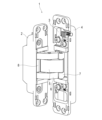
- FIG. 1 is a perspective view of a hinge according to a first embodiment of the present invention.
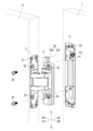
- 1 is a perspective view of the hinge of the present embodiment in a state in which the hinge body is fitted and fixed to the base frame.
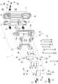
- FIG. FIG. 2 is an exploded perspective view of the hinge of the present embodiment.
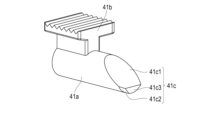
- FIG. 2 is an exploded perspective view of a main part of the hinge of the present embodiment.
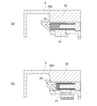
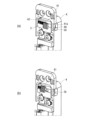
- FIG. 6A and 6B are horizontal cross-sectional views of the main part of the hinge of this embodiment (FIG. 6A shows the protruding position of the locking member, and FIG. 6B shows the retracted position of the locking member).
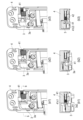
- FIG. 7(b1) to (b3) are cross-sectional views taken along line bb in FIGS.
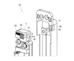
- FIG. 11 is a perspective view of a main part of a hinge according to a second embodiment of the present invention.
- FIG. 11A is a perspective view showing a state in which the hinge body is temporarily fixed to the base frame
- FIG. 11B is a perspective view showing a state in which the locking member is held in a retracted position.
- FIG. 1 is a perspective view showing a conventional hinge.
- the hinge 1 of the first embodiment of the present invention is a hidden hinge that includes a hinge body 2 that is attached to a door d, and a hinge body 3 that is attached to a mounting member f of the door (frame, cabinet, wall, etc.).
- the hinge body 2 and the hinge body 3 are connected via multiple arms 5 to 8 so that they can be opened and closed.
- the hinge 1 in this embodiment is not particularly limited, but it may be provided on some of the multiple hinges as long as the door d does not fall off.
- the multiple arms 5 to 8 include center arms 5 and 6 and side arms 7 and 8.
- the center arms 5 and 6 are formed in a roughly V-shape in plan view, and are rotatably connected by an axis 21 so that they cross at roughly the center.
- the base 5a of the center arm 5 is rotatably connected to an axis 22 supported by the bracket 12 of the hinge body 2.
- the tip 5b of the center arm 5 is rotatably connected to the tip of the side arm 7 by an axis 23.
- the base end of the side arm 7 is rotatably connected to an axis 24 supported by the bracket 15 of the hinge body 3.
- the base 6a of the center arm 6 is rotatably connected to an axis 25 supported by the bracket 15 of the hinge body 3.
- the tip 6b of the center arm 6 is rotatably connected to the tip of the side arm 8 by an axis 26.
- the base end of the side arm 8 is rotatably connected to an axis 27 supported by the bracket 12 of the hinge body 2.
- Reference numerals 28 and 29 denote spacers to prevent contact between metals.
- arms 5 to 8 is not limited to the above.
- side arms 7 and 8 may be omitted, and the tips of center arms 5 and 6 may be connected to bracket 12 of hinge body 2 and bracket 15 of hinge body 3 via an axis so as to be rotatable and slidable.
- hinge 1 may be a one-axis hinge, and hinge body 2 and hinge body 3 may be connected to each other rotatably via an axis.
- the hinge body 2 is fitted into a recess provided at the edge of the door d, and then fixed to the door d with a screw 31.
- a base frame (not shown) may be fixed to the door d, and the hinge body 2 may be fitted and fixed to the base frame.
- the hinge body 3 is fitted and fixed to the base frame 4 which is fixed to the mounting member f of the door. That is, the base frame 4 is fitted into a recess provided on the inner surface of the mounting member f and the base frame 4 is fixed to the mounting member f of the door with the screws 32. After that, the hinge body 3 is fitted into the base frame 4 and then the hinge body 3 is fixed to the base frame 4 with the screws 33.
- the hinge body 3 is provided with a screw 33 for adjusting the up-down position of the door d and a screw 34 for adjusting the front-rear position of the door d.
- the hinge body 2 is provided with a screw 35 for adjusting the left-right position of the door d.
- An example of the position adjustment structure is described below, but the position adjustment structure is not limited to this.
- the base frame 4 is provided with an insert nut (female thread) 37 into which the up-down position adjustment screw 33 screws.
- the insert nut 37 may be formed integrally with the base frame 4.
- the hinge body 3 includes a main body frame 14 that is fixed to the base frame 4 so that its up-down position can be adjusted, and a bracket 15 that is fixed to the main body frame 14 so that its front-rear position can be adjusted.
- the main frame 14 has a vertically extending long hole 14a through which the vertical position adjustment screw 33 passes. With the vertical position adjustment screw 33 loosened, the main frame 14 can be adjusted by moving it vertically relative to the base frame 4. After adjustment, the main frame 14 is fixed to the base frame 4 using the vertical position adjustment screw 33.
- the hinge body 2 comprises a body frame 11 fixed to the door d, and a bracket 12 fixed to the body frame 11 so that its left-right position can be adjusted.
- a recess 11a that matches the shape of the bracket 12 is formed in the body frame 11.
- a left-right adjustment screw 35 is supported on the body frame 11 so that it can rotate but cannot move axially.
- the left-right adjustment screw 35 screws into the bracket 12. When the left-right adjustment screw 35 is turned, the bracket 12 moves left-right relative to the body frame 11 due to the action of the feed screw.
- a locking member 41 is provided on the base frame 4 so as to be slidable.
- a biasing member 42 that biases the locking member 41 is also provided on the base frame 4.
- the hinge body 2 is temporarily fixed to the base frame 4 using the locking member 41.
- the position of the locking member 41 can be held at a protruding position shown in FIG. 6(a) and a retracted position retracted from this protruding position shown in FIG. 6(b).
- the amount of protrusion of the locking member 41 from the wall surface 45d in the protruding position is indicated by P1
- the amount of protrusion of the locking member 41 from the wall surface 45d in the retracted position is indicated by P2.
- the locking member 41 is rotated in a locking direction A and an unlocking direction B to switch the position of the locking member 41 between a retracted position and an extended position.
- a wall portion 45 having a wall surface 45d that faces the cam 3a (see FIG. 2) of the hinge body 3 is formed on the upper portion of the base frame 4.
- a guide groove 45a with an arc-shaped cross section that slidably guides the slide shaft 41a of the locking member 41 is formed on this wall portion 45.
- the locking member 41 can rotate a predetermined angle in the locking direction A and the unlocking direction B around the slide shaft 41a.
- a first stopper 45b and a second stopper 45c against which the locking member 41 abuts are formed on the wall portion 45.
- the locking member 41 includes a slide shaft 41a and an operating plate 41b that is integrally formed on the outer surface of the slide shaft 41a.
- the slide shaft 41a is cylindrical with a bottom (see FIG. 4).
- the biasing member 42 is housed inside the slide shaft 41a.
- a cam 41c is formed at the tip of the slide shaft 41a.
- the cam 41c has a first cam surface 41c1 consisting of a large inclined surface on the front side, a second cam surface 41c2 consisting of a small inclined surface on the back side, and an abutment cam surface 41c3 perpendicular to the slide shaft 41a.
- the operating plate 41b is roughly T-shaped when viewed in the axial direction.
- the upper surface of the operating plate 41b is formed with serrations to prevent slipping.
- the biasing member 42 is, for example, a coil spring.
- the biasing member 42 is interposed between the locking member 41 and the spring receiver 43, and biases the locking member 41 toward the hinge body 3.
- the biasing member 42 is not limited to a coil spring, and may be a disc spring, a leaf spring, or the like.
- a spring retainer 43 is fixed to the end of the guide groove 45a of the base frame 4.
- the spring retainer 43 has a large-diameter knurled portion 43a that is fixed to the end of the guide groove 45a, and a small-diameter support shaft 43b that is inserted into the biasing member 42.
- a cam 3a extending in the vertical direction is formed on the upper end of the hinge body 3.
- the cam 3a has a V-shaped cross section and includes a first cam surface 3a1 on the front side and a second cam surface 3a2 on the back side.
- the first cam surface 3a1 and the second cam surface 3a2 are formed into flat inclined surfaces.
- Figure 7 shows an example of an operation diagram when fitting the hinge body 3 into the base frame 4.
- the position of the locking member 41 is held in the protruding position ( Figure 6 (a)).
- Figures 7 (a1) and (b1) when the hinge body 3 is fitted into the base frame 4, the second cam surface 3a2 of the cam 3a of the hinge body 3 comes into contact with the first cam surface 41c1 of the cam 41c of the locking member 41, and the locking member 41 slides backward.
- the biasing member 42 slides the locking member 41 forward toward the hinge body 3, as shown in Figures 7 (a3) and (b3).
- the locking member 41 advances until the protruding position or the abutting cam surface 41c3 abuts against the hinge body 3. This prevents the hinge body 3 from coming off the base frame 4, and allows the hinge body 3 to be temporarily fixed to the base frame 4.
- Figure 8 shows an example of an operation diagram when removing the hinge body 3 from the base frame 4.
- the worker slides the locking member 41 in the backward direction, then rotates it in the locking direction to hold the locking member 41 in the retracted position ( Figure 8 (b1)).
- Figures 8 (a2) and (b2) when the hinge body 3 is pulled out from the base frame 4, the first cam surface 3a1 of the cam 3a of the hinge body 3 comes into contact with the second cam surface 41c2 of the cam 41c of the locking member 41, and the locking member 41 slides in the backward direction.
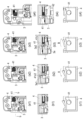
- FIG. 9 shows another example of the operation diagram when the hinge body 3 is fitted into the base frame 4.
- the worker slides the locking member 41 in the backward direction, and then rotates it in the locking direction to hold the locking member 41 in the retracted position (FIG. 9(b1)).
- the hinge body 3 is fitted into the base frame 4, as shown in FIG. 9(a2) and (b2), the second cam surface 3a2 of the cam 3a of the hinge body 3 comes into contact with the first cam surface 41c1 of the cam 41c of the locking member 41, and the locking member 41 slides in the backward direction.
- FIG. 9(a1) the worker slides the locking member 41 in the backward direction, and then rotates it in the locking direction to hold the locking member 41 in the retracted position (FIG. 9(b1)).
- a torque in the unlocking direction B acts on the locking member 41 by the second cam surface 3a2 of the hinge body 3 and the first cam surface 41c1 of the locking member 41, and the locking member 41 slides while rotating in the unlocking direction B.
- FIGS. 9(a3) and 9(b3) when the cam 3a of the hinge body 3 climbs over the cam 41c of the locking member 41, the biasing member 42 slides the locking member 41 toward the hinge body 3 to the protruding position.
- the hinge body 3 is temporarily fixed to the base frame 4 using a locking member 41 that is slidable relative to the base frame 4, making it easy to temporarily fix the hinge body 3 to the base frame 4.
- the position of the locking member 41 can be easily changed by rotating the locking member 41 in the locking direction A and the unlocking direction B to switch between the retracted position and the extended position.
- the locking member 41 can be disposed on the front side of the hinge body 3 in the provisionally fastened state, making it easy to check the provisionally fastened state.
- FIG. 10 shows a perspective view of the main parts of a hinge 47 according to a second embodiment of the present invention.
- Reference numeral 3 denotes the hinge body
- reference numeral 4 denotes the base frame.
- a locking member 41 and a biasing member 42 are provided on the hinge body 3 side.
- a hole 48 is formed in the base frame 4 into which the locking member 41 can be locked.
- the configurations of the hinge body 3 and base frame 4 are substantially the same as those of the hinge 1 of the first embodiment except for the above points, so the same reference numerals are used and their explanations are omitted.
- the configurations of the locking member 41, the biasing member 42, and the spring bearing 43 are also substantially the same as those of the hinge 1 of the first embodiment except for the above points, so the same reference numerals are used and their explanations are omitted.
- the position of the locking member 41 can be held in a protruding position shown in FIG. 10 and a retracted position shown in FIG. 11(b).
- the slide shaft 41a of the locking member 41 protrudes from the wall surface 3b of the hinge body 3.
- the slide shaft 41a of the locking member 41 retracts into the wall surface 3b of the hinge body 3.
- the locking member 41 is rotated in the locking direction A and the unlocking direction B to switch the position of the locking member 41 between the retracted position and the protruding position.
- the worker slides the locking member 41 in the backward direction and then rotates it in the locking direction A to hold the locking member 41 in the retracted position. In this state, the hinge body 3 can be removed from the base frame 4 by pulling it out of the base frame 4.
- the hinge 47 of the second embodiment provides the following advantages. Since the hinge body 3 is temporarily fixed to the base frame 4 using the locking member 41 that is slidable relative to the hinge body 3, the task of temporarily fixing the hinge body 3 to the base frame 4 can be easily performed.
- the position of the locking member 41 can be held in the protruding position and the retracted position, so the hinge body 3 can be easily removed from the base frame 4.
- the position of the locking member 41 can be easily changed by rotating the locking member 41 in the locking direction A and the unlocking direction B to switch between the retracted position and the extended position.
- hinge 2 hinge body 3: hinge body 4: base frame 41: locking member 42: biasing member 47: hinge A: locking direction B: unlocking direction
Landscapes
- Engineering & Computer Science (AREA)
- Mechanical Engineering (AREA)
- Hinges (AREA)
Abstract
Description
本発明は、扉に取り付けられるヒンジ本体と扉の取付部材(例えば枠、キャビネット本体、壁等)に取り付けられるヒンジ本体とが開閉可能に連結されるヒンジに関する。 The present invention relates to a hinge in which a hinge body attached to a door and a hinge body attached to a mounting member of the door (e.g., a frame, a cabinet body, a wall, etc.) are connected so as to be able to open and close.
図12に示すように、扉に取り付けられるヒンジ本体51と扉の取付部材に取り付けられるヒンジ本体52とが開閉可能に連結されるヒンジが知られている。ベースフレーム53は、取付部材への扉の取り付けを容易にするために使用される。すなわち、扉にヒンジ本体51を固定し、取付部材にベースフレーム53を固定し、扉を支持した状態でヒンジ本体52をベースフレーム53に嵌め込み固定する。
As shown in FIG. 12, a hinge is known in which a
しかし、ヒンジ本体52をベースフレーム53に嵌め込んだ状態で、ヒンジ本体52がベースフレーム53から抜け出てしまうと、ねじ54を用いてヒンジ本体52をベースフレーム53に固定できない。これを防止するため、ヒンジ本体52をベースフレーム53に仮止めしている。すなわち、ベースフレーム53の下部に穴53aを設け、ヒンジ本体52の下部に凸部52aを設け、ヒンジ本体52をベースフレーム53に嵌め込んだ状態で、ヒンジ本体52の凸部52aがベースフレーム53の穴53aに嵌り、扉の自重によってヒンジ本体52をベースフレーム53に仮止めしている。同様なヒンジの仮止め構造は、特許文献1の図4にも開示されている。
However, if the
しかし、従来のヒンジにおいては、ベースフレーム53の穴53a及びヒンジ本体52の凸部52aが奥側にあるので、見づらく、穴53aに凸部52aが嵌まっているかを確認しにくい。
However, in conventional hinges, the
本発明は、ヒンジ本体をベースフレームに仮止めする作業を容易にすることができるヒンジを提供することを目的とする。 The present invention aims to provide a hinge that makes it easy to temporarily attach the hinge body to the base frame.
上記課題を解決するために、本発明の一態様は、扉に取り付けられるヒンジ本体と扉の取付部材に取り付けられるヒンジ本体とが開閉可能に連結され、扉又は扉の取付部材の一方に取り付けられるヒンジ本体が扉又は扉の取付部材の一方に固定されるベースフレームに嵌め込み固定されるヒンジにおいて、前記ベースフレーム又は前記ヒンジ本体の一方にスライド可能に係止部材を設けると共に、前記係止部材を付勢する付勢部材を設け、前記係止部材を用いて前記ヒンジ本体を前記ベースフレームに仮止めするヒンジである。 In order to solve the above problems, one aspect of the present invention is a hinge in which a hinge body attached to a door and a hinge body attached to a mounting member of the door are connected so as to be able to open and close, and the hinge body attached to one of the door or the mounting member of the door is fitted and fixed to a base frame which is fixed to the door or the mounting member of the door, in which a locking member is provided slidably on one of the base frame or the hinge body, and a biasing member is provided to bias the locking member, and the locking member is used to temporarily secure the hinge body to the base frame.
本発明によれば、ヒンジ本体をベースフレームに仮止めする作業を容易にすることができる。 The present invention makes it easy to temporarily attach the hinge body to the base frame.
以下、添付図面に基づいて、本発明の実施形態のヒンジを詳細に説明する。ただし、本発明のヒンジは種々の形態で具体化することができ、本明細書に記載される実施形態に限定されるものではない。本実施形態は、明細書の開示を十分にすることによって、当業者が発明を十分に理解できるようにする意図をもって提供されるものである。
(第1実施形態)
Hereinafter, a hinge according to an embodiment of the present invention will be described in detail with reference to the accompanying drawings. However, the hinge according to the present invention can be embodied in various forms and is not limited to the embodiments described in the present specification. The present embodiment is provided with the intention of enabling a person skilled in the art to fully understand the invention by fully disclosing the specification.
First Embodiment
図1及び図2に示すように、本発明の第1実施形態のヒンジ1は、扉dに取り付けられるヒンジ本体2と、扉の取付部材f(枠、キャビネット、壁等)に取り付けられるヒンジ本体3と、を備える隠し蝶番である。ヒンジ本体2とヒンジ本体3とは、複数本のアーム5~8を介して開閉可能に連結される。
As shown in Figures 1 and 2, the
通常、扉dの上下には複数のヒンジが設けられる。本実施形態のヒンジ1は、特に限定されるものではないが、扉dが脱落しなければ、複数のヒンジのうちの一部に設ければよい。
Normally, multiple hinges are provided above and below the door d. The
以下に、閉じ位置にある扉dを開き側から見た方向、すなわち図2の上下、左右、前後の各方向を用いてヒンジ1の構成を説明する。
Below, the configuration of the
図1に示すように、複数本のアーム5~8は、センターアーム5,6と、サイドアーム7,8と、を備える。図3に示すように、センターアーム5,6は、平面視が略への字状に形成されており、それらが略中央部でクロスするように軸21により回転自在に連結される。
As shown in FIG. 1, the
センターアーム5の基部5aは、ヒンジ本体2のブラケット12に支持される軸22に回転自在に連結される。センターアーム5の先端部5bは、サイドアーム7の先端部に軸23により回転自在に連結される。サイドアーム7の基端部は、ヒンジ本体3のブラケット15に支持される軸24に回転自在に連結される。
The
センターアーム6の基部6aは、ヒンジ本体3のブラケット15に支持される軸25に回転自在に連結される。センターアーム6の先端部6bは、サイドアーム8の先端部に軸26により回転自在に連結される。サイドアーム8の基端部は、ヒンジ本体2のブラケット12に支持される軸27に回転自在に連結される。符号28,29は、金属同士の接触を防止するためのスペーサである。
The
アーム5~8の構成は、上記に限られない。例えばサイドアーム7,8を省略し、センターアーム5,6の先端部をヒンジ本体2のブラケット12及びヒンジ本体3のブラケット15に軸により回転自在にかつスライド自在に連結してもよい。また、ヒンジ1を1軸ヒンジにし、ヒンジ本体2とヒンジ本体3とを軸を介して互いに回転可能に連結してもよい。
The configuration of
図2に示すように、ヒンジ本体2は、扉dの小口に設けた凹所に嵌め込んだ後、ねじ31によって扉dに固定される。なお、扉dに図示しないベースフレームを固定し、ベースフレームにヒンジ本体2を嵌め込み固定してもよい。
As shown in FIG. 2, the
一方、ヒンジ本体3は、扉の取付部材fに固定されるベースフレーム4に嵌め込み固定される。すなわち、取付部材fの内面に設けた凹所にベースフレーム4を嵌め込み、ねじ32によってベースフレーム4を扉の取付部材fに固定しておき、その後、ベースフレーム4にヒンジ本体3を嵌め込んだ後、ねじ33によってヒンジ本体3をベースフレーム4に固定する。
On the other hand, the
図3に示すように、ベースフレーム4には、上下方向に細長い凹部4aが形成される。凹部4aは、底壁と、底壁を枠状に囲む側壁とによって形成される。凹部4aの上下方向の長さは、ヒンジ本体3の上下方向の長さよりも所定長さだけ長い。ヒンジ本体3は、凹部4aに嵌め外し自在であり、上下方向に移動可能である。ベースフレーム4の上下の側壁には、フランジ4bが延設される。フランジ4bには、ねじ32(図2参照)の通し穴が形成される。
As shown in FIG. 3, the
ヒンジ本体3には、扉dの上下位置調節ねじ33及び前後位置調節ねじ34が設けられる。ヒンジ本体2には、扉dの左右位置調節ねじ35が設けられる。以下に位置調節構造の一例を説明するが、位置調節構造はこれに限定されるものではない。
The
ベースフレーム4には、上下位置調節ねじ33が螺合するインサートナット(雌ねじ)37が設けられる。ベースフレーム4にインサートナット37を一体に形成してもよい。ヒンジ本体3は、ベースフレーム4に上下位置調節可能に固定される本体フレーム14と、本体フレーム14に前後位置調節可能に固定されるブラケット15と、を備える。
The
本体フレーム14には、上下位置調節ねじ33が通る上下方向に延びる長穴14aが形成される。上下位置調節ねじ33を緩めた状態で、本体フレーム14をベースフレーム4に対して上下方向に移動調節できる。調節後、本体フレーム14は、ベースフレーム4に上下位置調節ねじ33を用いて固定される。
The
本体フレーム14には、前後位置調節ねじ34が螺合するねじ穴14bが形成される。ブラケット15には、前後位置調節ねじ34が通る前後方向に延びる長穴15aが形成される。前後位置調節ねじ34を緩めた状態で、ブラケット15を本体フレーム14に対して前後方向に移動調節できる。
The
ヒンジ本体2は、扉dに固定される本体フレーム11と、本体フレーム11に左右位置調節可能に固定されるブラケット12と、を備える。本体フレーム11には、ブラケット12に形状を合わせた凹部11aが形成される。本体フレーム11には、左右調節ねじ35が回転可能に軸方向に移動不可能に支持される。左右調節ねじ35は、ブラケット12に螺合する。左右調節ねじ35を回すと、送りねじの作用によって、本体フレーム11に対してブラケット12が左右方向に移動する。
The
図4に示すように、ベースフレーム4には、スライド可能に係止部材41が設けられる。また、ベースフレーム4には、係止部材41を付勢する付勢部材42が設けられる。そして、この係止部材41を用いてヒンジ本体2をベースフレーム4に仮止めする。
As shown in FIG. 4, a locking
係止部材41の位置は、図6(a)に示す突出位置とこの突出位置より引っ込んだ図6(b)に示す引っ込み位置とに保持可能である。突出位置における壁面45dからの係止部材41の突出量をP1で示し、引っ込み位置における壁面45dからの係止部材41の突出量をP2で示す。
The position of the locking
図4に示すように、係止部材41をロック方向A及びロック解除方向Bに回転させて、係止部材41の位置を引っ込み位置と突出位置に切り替える。
As shown in FIG. 4, the locking
ベースフレーム4の上部には、ヒンジ本体3のカム3a(図2参照)に対向する壁面45dを有する壁部45が形成される。この壁部45には、係止部材41のスライド軸41aをスライド可能に案内する断面円弧状の案内溝45aが形成される。係止部材41は、スライド軸41aを中心にロック方向A及びロック解除方向Bに所定角度だけ回転できる。壁部45には、係止部材41が突き当たる第1ストッパ45bと第2ストッパ45cが形成される。
A
図5に示すように、係止部材41は、スライド軸41aと、スライド軸41aの外面に一体に形成される作動プレート41bと、を備える。スライド軸41aは、有底円筒状である(図4参照)。スライド軸41aの内部には、付勢部材42が収容される。
As shown in FIG. 5, the locking
スライド軸41aの先端部には、カム41cが形成される。カム41cは、表側の大きい傾斜面からなる第1カム面41c1と、裏側の小さい傾斜面からなる第2カム面41c2と、スライド軸41aに直角な突当てカム面41c3と、を備える。
A
作動プレート41bは、軸方向視が略T字状である。作動プレート41bの上面には、滑り止めのためのギザギザが形成される。
The
図4に示すように、付勢部材42は、例えばコイルばねである。付勢部材42は、係止部材41とばね受け43との間に介在し、係止部材41をヒンジ本体3に向かって付勢する。付勢部材42は、コイルばねに限られず、皿ばね、板ばね等でもよい。
As shown in FIG. 4, the biasing
ベースフレーム4の案内溝45aの端部には、ばね受け43が固定される。ばね受け43は、案内溝45aの端部に固定される大径のローレット部43aと、付勢部材42に挿入される小径の支持軸43bと、を備える。
A
図4に示すように、作業者が係止部材41の作動プレート41bの下端部を押して係止部材41をロック解除方向Bに回転させれば、係止部材41が付勢部材42によって付勢されて前進方向にスライドし、作動プレート41bが第1ストッパ45bに当接する。このため、係止部材41の位置を突出位置(図6(a))に保持することができる。一方、作業者が係止部材41の作動プレート41bを付勢部材42に抗して後退方向にスライドさせ、作動プレート41bの上端部を押して係止部材41をロック方向Aに回転させれば、作動プレート41bが第2ストッパ45cに当接する。このため、係止部材41の位置を引っ込み位置(図6(b))に保持することができる。
As shown in FIG. 4, when an operator presses the lower end of the
図2に示すように、ヒンジ本体3をベースフレーム4に嵌め込む際、ヒンジ本体3が係止部材41に接触して、係止部材41がスライドする。ヒンジ本体3の上端部には、上下方向に延びるカム3aが形成される。カム3aは、断面V字状であり、表側の第1カム面3a1と、裏側の第2カム面3a2と、を備える。第1カム面3a1と第2カム面3a2は、平らな傾斜面に形成される。
As shown in FIG. 2, when the
図7は、ヒンジ本体3をベースフレーム4に嵌め込む際の動作図の一例を示す。この例では、係止部材41の位置は、突出位置(図6(a))に保持されている。図7(a1)(b1)に示すように、ヒンジ本体3をベースフレーム4に嵌め込めば、ヒンジ本体3のカム3aの第2カム面3a2が係止部材41のカム41cの第1カム面41c1に接触して、係止部材41が後退方向にスライドする。その後、図7(a2)(b2)に示すように、ヒンジ本体3のカム3aが係止部材41のカム41cを乗り越えると、図7(a3)(b3)に示すように、付勢部材42が係止部材41をヒンジ本体3に向かって前進方向にスライドさせる。このとき、係止部材41は、突出位置又は突当てカム面41c3がヒンジ本体3に突き当たるまで前進する。したがって、ヒンジ本体3がベースフレーム4から抜けるのを防止でき、ヒンジ本体3をベースフレーム4に仮止めすることができる。
Figure 7 shows an example of an operation diagram when fitting the
図8は、ヒンジ本体3をベースフレーム4から取り外す際の動作図の一例を示す。この例では、まず、図8(a1)に示すように、作業者が係止部材41を後退方向にスライドさせた後、ロック方向に回転させ、係止部材41の位置を引っ込み位置(図8(b1))に保持する。そして、図8(a2)(b2)に示すように、ヒンジ本体3をベースフレーム4から引き抜くと、ヒンジ本体3のカム3aの第1カム面3a1が係止部材41のカム41cの第2カム面41c2に接触して、係止部材41が後退方向にスライドする。このとき、図8(c2)に示すように、ヒンジ本体3の第1カム面3a1と係止部材41の第2カム面41c2によって、係止部材41にはロック方向Aにトルクが働く。このため、係止部材41は、ロック状態を保ったままスライドする。その後、図8(a3)(b3)に示すように、ヒンジ本体3のカム3aが係止部材41のカム41cを乗り越えれば、図8(a4)(b4)に示すように、付勢部材42が係止部材41をヒンジ本体3に向かって前進方向にスライドさせる。このとき、図8(c3)に示すように、ヒンジ本体3の第2カム面3a2と係止部材41の第1カム面41c1によって、係止部材41にはロック解除方向Bのトルクが働き、係止部材41はロック解除方向Bに回転しながら突出位置(図8(b4))まで前進する。
Figure 8 shows an example of an operation diagram when removing the
図9は、ヒンジ本体3をベースフレーム4に嵌め込む際の動作図の他の例を示す。この例では、まず図9(a1)に示すように、作業者が係止部材41を後退方向にスライドさせた後、ロック方向に回転させ、係止部材41の位置を引っ込み位置(図9(b1))に保持する。そして、ヒンジ本体3をベースフレーム4に嵌め込むと、図9(a2)(b2)に示すように、ヒンジ本体3のカム3aの第2カム面3a2が係止部材41のカム41cの第1カム面41c1に接触して、係止部材41が後退方向にスライドする。このとき、ヒンジ本体3の第2カム面3a2と係止部材41の第1カム面41c1によって、図9(c2)に示すように、係止部材41にロック解除方向Bのトルクが働き、係止部材41はロック解除方向Bに回りながらスライドする。その後、図9(a3)(b3)に示すように、ヒンジ本体3のカム3aが係止部材41のカム41cを乗り越えれば、付勢部材42が係止部材41をヒンジ本体3に向かって突出位置までスライドさせる。
以下に本実施形態のヒンジの効果を説明する。
9 shows another example of the operation diagram when the
The effects of the hinge of this embodiment will be described below.
本実施形態のヒンジ1によれば、ベースフレーム4に対してスライド可能な係止部材41を用いて、ヒンジ本体3をベースフレーム4に仮止めするので、ヒンジ本体3をベースフレーム4に仮止めする作業を容易にすることができる。
In the
係止部材41の位置を突出位置と引っ込み位置とに保持可能であるので、ヒンジ本体3をベースフレーム4から容易に取り外し、又はヒンジ本体3をベースフレーム4に容易に嵌め込むことができる。
The position of the locking
係止部材41をロック方向A及びロック解除方向Bに回転させて、係止部材41の位置を引っ込み位置と突出位置に切り替えるので、係止部材41の位置の切り替えが容易である。
The position of the locking
ベースフレーム4に係止部材41と付勢部材42を設けるので、仮止め状態において係止部材41をヒンジ本体3の前面側に配置でき、仮止め状態を確認し易い。
(第2実施形態)
Since the
Second Embodiment
図10は、本発明の第2実施形態のヒンジ47の主要部の斜視図を示す。符号3はヒンジ本体、符号4はベースフレームである。第2実施形態のヒンジ47では、係止部材41と付勢部材42がヒンジ本体3側に設けられる。ベースフレーム4には、係止部材41が係止可能な穴48が形成される。
FIG. 10 shows a perspective view of the main parts of a
ヒンジ本体3、ベースフレーム4の構成は、上記の点を除いて、第1実施形態のヒンジ1と略同一であるので、同一の符号を附してその説明を省略する。係止部材41、付勢部材42、ばね受け43の構成も、上記の点を除いて、第1実施形態のヒンジ1と略同一であるので、同一の符号を附してその説明を省略する。
The configurations of the
係止部材41の位置は、図10に示す突出位置と図11(b)に示す引っ込み位置とに保持可能である。図10に示す突出位置において、係止部材41のスライド軸41aはヒンジ本体3の壁面3bから突出する。図11(b)に示す引っ込み位置において、係止部材41のスライド軸41aはヒンジ本体3の壁面3b内に引っ込む。図10に示すように、係止部材41をロック方向A及びロック解除方向Bに回転させて、係止部材41の位置を引っ込み位置と突出位置に切り替える。
The position of the locking
図10に示すように、ヒンジ本体3をベースフレーム4に嵌め込む際、係止部材41がベースフレーム4の穴48の前壁50に接触して、係止部材41が後退方向にスライドする。その後、図11(a)に示すように、係止部材41がベースフレーム4の前壁50を乗り越えると、付勢部材42が係止部材41を前進方向にスライドさせ、係止部材41がベースフレーム4の穴48に係止する。したがって、ヒンジ本体3がベースフレーム4から抜けるのを防止でき、ヒンジ本体3をベースフレーム4に仮止めすることができる。
As shown in Figure 10, when the
ヒンジ本体3をベースフレーム4から取り外す際は、図11(b)に示すように、作業者が係止部材41を後退方向にスライドさせた後、ロック方向Aに回転させ、係止部材41の位置を引っ込み位置に保持する。この状態で、ヒンジ本体3をベースフレーム4から引き抜けば、ヒンジ本体3をベースフレーム4から取り外すことができる。
When removing the
第2実施形態のヒンジ47によれば、以下の効果を奏する。
ヒンジ本体3に対してスライド可能な係止部材41を用いて、ヒンジ本体3をベースフレーム4に仮止めするので、ヒンジ本体3をベースフレーム4に仮止めする作業を容易にすることができる。
The
Since the
係止部材41の位置を突出位置と引っ込み位置とに保持可能であるので、ヒンジ本体3をベースフレーム4から容易に取り外すことができる。
The position of the locking
係止部材41をロック方向A及びロック解除方向Bに回転させて、係止部材41の位置を引っ込み位置と突出位置に切り替えるので、係止部材41の位置の切り替えが容易である。
The position of the locking
本明細書は、2023年10月27日出願の特願2023-184432に基づく。この内容はすべてここに含めておく。 This specification is based on Japanese Patent Application No. 2023-184432, filed on October 27, 2023, the entire contents of which are incorporated herein by reference.
1…ヒンジ
2…ヒンジ本体
3…ヒンジ本体
4…ベースフレーム
41…係止部材
42…付勢部材
47…ヒンジ
A…ロック方向
B…ロック解除方向
REFERENCE SIGNS LIST 1: hinge 2: hinge body 3: hinge body 4: base frame 41: locking member 42: biasing member 47: hinge A: locking direction B: unlocking direction
Claims (4)
前記ベースフレーム又は前記ヒンジ本体の一方にスライド可能に係止部材を設けると共に、前記係止部材を付勢する付勢部材を設け、
前記係止部材を用いて前記ヒンジ本体を前記ベースフレームに仮止めするヒンジ。 A hinge in which a hinge body attached to a door and a hinge body attached to a mounting member of the door are connected so as to be able to open and close, and the hinge body attached to one of the door or the mounting member of the door is fitted and fixed to a base frame fixed to the door or the mounting member of the door,
a locking member is slidably provided on one of the base frame and the hinge body, and a biasing member is provided to bias the locking member;
The hinge body is temporarily fixed to the base frame by using the locking member.
Priority Applications (3)
| Application Number | Priority Date | Filing Date | Title |
|---|---|---|---|
| CN202480068186.6A CN122070411A (en) | 2023-10-27 | 2024-10-11 | hinge |
| JP2025553153A JPWO2025089106A1 (en) | 2023-10-27 | 2024-10-11 | |
| US19/568,788 US20260210165A1 (en) | 2023-10-27 | 2026-03-17 | Hinge |
Applications Claiming Priority (2)
| Application Number | Priority Date | Filing Date | Title |
|---|---|---|---|
| JP2023-184432 | 2023-10-27 | ||
| JP2023184432 | 2023-10-27 |
Related Child Applications (1)
| Application Number | Title | Priority Date | Filing Date |
|---|---|---|---|
| US19/568,788 Continuation US20260210165A1 (en) | 2023-10-27 | 2026-03-17 | Hinge |
Publications (1)
| Publication Number | Publication Date |
|---|---|
| WO2025089106A1 true WO2025089106A1 (en) | 2025-05-01 |
Family
ID=95515888
Family Applications (1)
| Application Number | Title | Priority Date | Filing Date |
|---|---|---|---|
| PCT/JP2024/036372 Pending WO2025089106A1 (en) | 2023-10-27 | 2024-10-11 | Hinge |
Country Status (4)
| Country | Link |
|---|---|
| US (1) | US20260210165A1 (en) |
| JP (1) | JPWO2025089106A1 (en) |
| CN (1) | CN122070411A (en) |
| WO (1) | WO2025089106A1 (en) |
Citations (4)
| Publication number | Priority date | Publication date | Assignee | Title |
|---|---|---|---|---|
| JPS62121288A (en) * | 1985-11-19 | 1987-06-02 | 余合住金産業株式会社 | Hinge |
| JPH05113068A (en) * | 1991-10-23 | 1993-05-07 | Sugatsune Ind Co Ltd | Hinge |
| JP2009097271A (en) * | 2007-10-18 | 2009-05-07 | Daiken Corp | Open door structure |
| JP2018066203A (en) * | 2016-10-20 | 2018-04-26 | 中西産業株式会社 | Pivot hinge |
-
2024
- 2024-10-11 CN CN202480068186.6A patent/CN122070411A/en active Pending
- 2024-10-11 WO PCT/JP2024/036372 patent/WO2025089106A1/en active Pending
- 2024-10-11 JP JP2025553153A patent/JPWO2025089106A1/ja active Pending
-
2026
- 2026-03-17 US US19/568,788 patent/US20260210165A1/en active Pending
Patent Citations (4)
| Publication number | Priority date | Publication date | Assignee | Title |
|---|---|---|---|---|
| JPS62121288A (en) * | 1985-11-19 | 1987-06-02 | 余合住金産業株式会社 | Hinge |
| JPH05113068A (en) * | 1991-10-23 | 1993-05-07 | Sugatsune Ind Co Ltd | Hinge |
| JP2009097271A (en) * | 2007-10-18 | 2009-05-07 | Daiken Corp | Open door structure |
| JP2018066203A (en) * | 2016-10-20 | 2018-04-26 | 中西産業株式会社 | Pivot hinge |
Also Published As
| Publication number | Publication date |
|---|---|
| JPWO2025089106A1 (en) | 2025-05-01 |
| US20260210165A1 (en) | 2026-07-23 |
| CN122070411A (en) | 2026-05-19 |
Similar Documents
| Publication | Publication Date | Title |
|---|---|---|
| US11168502B2 (en) | Door device | |
| US20240076907A1 (en) | Multi-point exit device | |
| JP5291834B2 (en) | Hinge device and base for hinge device | |
| JP2010133234A (en) | Shielding door hinge | |
| CN104220689B (en) | Hinge apparatus | |
| JP4980182B2 (en) | One-touch pad mounting mechanism | |
| JP2009167636A (en) | Hinge device and hinge device for folding door | |
| JP5291835B2 (en) | Hinge device | |
| WO2020110423A1 (en) | Glove compartment lock device | |
| CN122070411A (en) | hinge | |
| JP2511639Y2 (en) | Pivot pot hinge | |
| JPH0860929A (en) | Door stopper | |
| JP2017115297A (en) | Door roller | |
| JP7546274B2 (en) | Door closing assistance device | |
| JP3231669B2 (en) | Slide wing lock device | |
| JP7563867B2 (en) | ACTUATOR FOR SAFETY SWITCH AND SAFETY SWITCH EQUIPPED WITH THE ACTUATOR | |
| JPH09317286A (en) | Door lock | |
| JP6537880B2 (en) | Hinge | |
| JP6637557B1 (en) | Door opening holding structure and door stopper | |
| JP2006257861A (en) | Hidden pivot hinge and door with it | |
| JP3491772B2 (en) | Opening adjuster | |
| JP2001182424A (en) | Pivot part structure in the rotating member | |
| JP2005002715A (en) | Supporting device of overhanging door | |
| JP4337025B2 (en) | hinge | |
| JP3190539B2 (en) | Door opening adjuster |
Legal Events
| Date | Code | Title | Description |
|---|---|---|---|
| 121 | Ep: the epo has been informed by wipo that ep was designated in this application |
Ref document number: 24882219 Country of ref document: EP Kind code of ref document: A1 |
|
| ENP | Entry into the national phase |
Ref document number: 2025553153 Country of ref document: JP Kind code of ref document: A |
|
| WWE | Wipo information: entry into national phase |
Ref document number: 2025553153 Country of ref document: JP |
|
| NENP | Non-entry into the national phase |
Ref country code: DE |