WO2025089011A1 - 化学分析装置、中空糸脱気モジュール及び恒温水の脱気方法 - Google Patents
化学分析装置、中空糸脱気モジュール及び恒温水の脱気方法 Download PDFInfo
- Publication number
- WO2025089011A1 WO2025089011A1 PCT/JP2024/035540 JP2024035540W WO2025089011A1 WO 2025089011 A1 WO2025089011 A1 WO 2025089011A1 JP 2024035540 W JP2024035540 W JP 2024035540W WO 2025089011 A1 WO2025089011 A1 WO 2025089011A1
- Authority
- WO
- WIPO (PCT)
- Prior art keywords
- housing
- hollow fiber
- internal space
- fiber membrane
- joint structure
- Prior art date
- Legal status (The legal status is an assumption and is not a legal conclusion. Google has not performed a legal analysis and makes no representation as to the accuracy of the status listed.)
- Pending
Links
Images


Classifications
-
- B—PERFORMING OPERATIONS; TRANSPORTING
- B01—PHYSICAL OR CHEMICAL PROCESSES OR APPARATUS IN GENERAL
- B01D—SEPARATION
- B01D61/00—Processes of separation using semi-permeable membranes, e.g. dialysis, osmosis or ultrafiltration; Apparatus, accessories or auxiliary operations specially adapted therefor
-
- B—PERFORMING OPERATIONS; TRANSPORTING
- B01—PHYSICAL OR CHEMICAL PROCESSES OR APPARATUS IN GENERAL
- B01D—SEPARATION
- B01D63/00—Apparatus in general for separation processes using semi-permeable membranes
- B01D63/02—Hollow fibre modules
-
- B—PERFORMING OPERATIONS; TRANSPORTING
- B01—PHYSICAL OR CHEMICAL PROCESSES OR APPARATUS IN GENERAL
- B01D—SEPARATION
- B01D71/00—Semi-permeable membranes for separation processes or apparatus characterised by the material; Manufacturing processes specially adapted therefor
- B01D71/06—Organic material
- B01D71/26—Polyalkenes
-
- B—PERFORMING OPERATIONS; TRANSPORTING
- B01—PHYSICAL OR CHEMICAL PROCESSES OR APPARATUS IN GENERAL
- B01D—SEPARATION
- B01D71/00—Semi-permeable membranes for separation processes or apparatus characterised by the material; Manufacturing processes specially adapted therefor
- B01D71/06—Organic material
- B01D71/30—Polyalkenyl halides
- B01D71/32—Polyalkenyl halides containing fluorine atoms
-
- B—PERFORMING OPERATIONS; TRANSPORTING
- B01—PHYSICAL OR CHEMICAL PROCESSES OR APPARATUS IN GENERAL
- B01D—SEPARATION
- B01D71/00—Semi-permeable membranes for separation processes or apparatus characterised by the material; Manufacturing processes specially adapted therefor
- B01D71/06—Organic material
- B01D71/48—Polyesters
-
- B—PERFORMING OPERATIONS; TRANSPORTING
- B01—PHYSICAL OR CHEMICAL PROCESSES OR APPARATUS IN GENERAL
- B01D—SEPARATION
- B01D71/00—Semi-permeable membranes for separation processes or apparatus characterised by the material; Manufacturing processes specially adapted therefor
- B01D71/06—Organic material
- B01D71/70—Polymers having silicon in the main chain, with or without sulfur, nitrogen, oxygen or carbon only
-
- C—CHEMISTRY; METALLURGY
- C02—TREATMENT OF WATER, WASTE WATER, SEWAGE, OR SLUDGE
- C02F—TREATMENT OF WATER, WASTE WATER, SEWAGE, OR SLUDGE
- C02F1/00—Treatment of water, waste water, or sewage
- C02F1/20—Treatment of water, waste water, or sewage by degassing, i.e. liberation of dissolved gases
-
- C—CHEMISTRY; METALLURGY
- C02—TREATMENT OF WATER, WASTE WATER, SEWAGE, OR SLUDGE
- C02F—TREATMENT OF WATER, WASTE WATER, SEWAGE, OR SLUDGE
- C02F1/00—Treatment of water, waste water, or sewage
- C02F1/44—Treatment of water, waste water, or sewage by dialysis, osmosis or reverse osmosis
-
- G—PHYSICS
- G01—MEASURING; TESTING
- G01N—INVESTIGATING OR ANALYSING MATERIALS BY DETERMINING THEIR CHEMICAL OR PHYSICAL PROPERTIES
- G01N35/00—Automatic analysis not limited to methods or materials provided for in any single one of groups G01N1/00 - G01N33/00; Handling materials therefor
Definitions
- the present invention relates to a chemical analyzer, a hollow fiber degassing module, and a method for degassing constant temperature water.
- the chemical analyzer is equipped with a degassing module with a hollow fiber membrane, and this degassing module has a mechanism for creating negative pressure on the outside or inside of the hollow fiber membrane, so that when the liquid passes through the inside or outside of the hollow fiber membrane, only the gas in the liquid is separated from the wall of the hollow fiber.
- Chemical analyzers are used, for example, to measure components of body fluids such as blood and urine, and are widely used in hospital laboratories and testing centers.
- a conventional chemical analysis device has been proposed that, for the purpose of miniaturizing the entire system and preventing a decline in the performance of the degassing section in the degassed water storage tank, enables degassing of dissolved gases in pure water by heating and maintaining the pure water taken in from the outside at a temperature slightly higher than the operating temperature in a degassing section composed mainly of a preheat tank (Patent Document 1).
- Patent Document 1 A conventional chemical analysis device has been proposed that, for the purpose of miniaturizing the entire system and preventing a decline in the performance of the degassing section in the degassed water storage tank, enables degassing of dissolved gases in pure water by heating and maintaining the pure water taken in from the outside at a temperature slightly higher than the operating temperature in a degassing section composed mainly of a preheat tank.
- Patent Document 1 proposes a storage tank for storing a large amount of degassed water, and cannot accommodate the miniaturization of the entire system.
- Patent Document 2 a hollow fiber degassing module made of silicone resin hollow fiber membranes, which has a mechanism in which negative pressure is applied to the outside of the hollow fiber membrane so that when the liquid passes through the inside of the hollow fiber membrane, only the gas in the liquid is separated from the wall of the hollow fiber.
- An effective way to solve this problem is to remove the dissolved gas from the RO water.
- Another method that can efficiently remove dissolved gas is to incorporate a hollow fiber degassing module into the chemical analysis device and perform continuous degassing.
- the performance requirements for a hollow fiber degassing module to be incorporated into the device include (1) having a specified degassing performance, (2) being small enough to be installed in the device, (3) having low pressure loss, and (4) having a long life.
- a bamboo shoot joint is generally used at the connection between the housing and the tube member.
- the hose band metal ring
- the tube member is pulled out each time, so stress is repeatedly applied to the bamboo shoot part of the joint, and the bamboo shoot joint is likely to break near the base due to tensile fatigue.
- a bamboo shoot joint is also used for the joint connected to the hollow fiber, and there is a concern that the bamboo shoot joint is prone to breaking and water leakage.
- the tube member when the tube member is inserted into the bamboo shoot joint, the tube is connected while being screwed, so stress is generated in a direction perpendicular to the axial direction of the bamboo shoot joint, making the bamboo shoot joint prone to breaking, and there is also a concern that compression fatigue and bending fatigue may occur due to repeated screwing.
- the bamboo shoot joint deteriorates as described above, gas or water leaks from the base of the bamboo shoot joint, and the original performance of the hollow fiber degassing module is reduced.
- friction between the bamboo joint and the tube member can cause the inner surface of the tube member to be scraped off, which can result in a decrease in the sealing ability between the bamboo joint and the tube member, making it easier for dirt (particles) to get in.
- the present invention aims to provide a hollow fiber degassing module that is small and has low pressure loss, and that can maintain its original good degassing performance even when used continuously for long periods of time, and that can also suppress the growth of bacteria, etc., as well as a chemical analyzer equipped with the hollow fiber degassing module and a method for degassing constant temperature water.
- the chemical analysis device in the first aspect of the present invention is a chemical analysis device for performing chemical or biochemical analysis of a sample, and includes a constant temperature bath for maintaining the temperature of a container containing the sample, and a degassing section having a hollow fiber degassing module for degassing dissolved gas contained in the constant temperature water in the constant temperature bath, the hollow fiber degassing module having a housing and a hollow fiber membrane arranged in the internal space of the housing, the housing connecting the outside of the housing with the internal space of the hollow fiber membrane, and supplying the constant temperature water from the outside of the housing to the inside of the hollow fiber membrane.
- a first liquid supply section for discharging the degassed constant temperature water from the internal space of the hollow fiber membrane to the outside of the housing
- a first liquid discharge section for connecting the internal space of the hollow fiber membrane to the outside of the housing and discharging the degassed constant temperature water from the internal space of the hollow fiber membrane to the outside of the housing
- at least one first gas discharge section for connecting the internal space of the housing to the outside of the housing and reducing the pressure in the internal space of the housing
- the hollow fiber degassing module has a one-touch joint structure or a luer fitting joint structure for connecting the housing and a tube member to the at least one first gas discharge section.
- the hollow fiber degassing module may further have a one-touch joint structure or a luer fitting joint structure in at least one of the first liquid supply section and the first liquid discharge section, which connects the housing and the tube member.
- the housing may have an extension section that is integral with the housing and extends outward from the housing to which the one-touch joint structure or the luer fitting joint structure is attached.
- the housing may further have at least one rib portion provided on the extension portion.
- the housing may have a cylinder arranged so that its axis is substantially horizontal, a first lid attached to one axial end of the cylinder, and a second lid attached to the other axial end of the cylinder, and the first liquid supply unit may be provided on the first lid, the first liquid discharge unit may be provided on the second lid, and the at least one first gas discharge unit may be provided on the cylinder.
- the cylinder may have a cylindrical shape with its axis parallel to the horizontal direction, and the at least one first gas exhaust section may be provided on the peripheral wall of the cylinder.
- the cylindrical body may have a first screw-type portion where the cylindrical body and the first lid portion screw together, and a second screw-type portion where the cylindrical body and the second lid portion screw together.
- the hollow fiber degassing module may have a first sealing portion that seals one axial end of the cylinder and a second sealing portion that seals the other axial end of the cylinder, and one longitudinal end of the hollow fiber membrane may be fixed to the first sealing portion, and the other longitudinal end of the hollow fiber membrane may be fixed to the second sealing portion.
- the hollow fiber membrane may be made of polyolefin resin, fluororesin or silicone resin.
- the housing may be made of polyolefin resin or aromatic polyester resin.
- the chemical analysis device in the second aspect of the present invention is a chemical analysis device for performing chemical analysis or biochemical analysis of a sample, and includes a constant temperature bath for maintaining the temperature of a container containing the sample, and a degassing section having a hollow fiber degassing module for degassing dissolved gas contained in the constant temperature water in the constant temperature bath, the hollow fiber degassing module having a housing and a hollow fiber membrane arranged in the internal space of the housing, the housing connecting the outside of the housing to the internal space of the housing, and supplying the constant temperature water from the outside of the housing to the internal space of the housing.
- a second liquid supply section for supplying degassed constant temperature water to the housing
- a second liquid discharge section for connecting the internal space of the housing to the outside of the housing and discharging the degassed constant temperature water from the internal space of the housing to the outside of the housing
- at least one second gas discharge section for connecting the internal space of the hollow fiber membrane to the outside of the housing and reducing the pressure in the internal space of the hollow fiber membrane
- the hollow fiber degassing module has a one-touch joint structure or a luer fitting joint structure for connecting the housing and a tube member to the at least one second gas discharge section.
- the hollow fiber degassing module may further have a one-touch joint structure or a luer fitting joint structure in at least one of the second liquid supply section and the second liquid discharge section, which connects the housing and the tube member.
- the housing may have an extension section that is integral with the housing and extends outward from the housing to include the one-touch joint structure or the luer fitting joint structure.
- the housing may further have at least one rib portion provided on the extension portion.
- the housing may have a cylinder arranged so that its axis is substantially vertical, a third lid attached to the axial lower end of the cylinder, and a fourth lid attached to the axial upper end of the cylinder, and the second liquid supply unit may be provided on the cylinder, the second liquid discharge unit may be provided on the fourth lid, and the at least one second gas discharge unit may be provided on the third lid.
- the at least one second gas exhaust section may be provided in the third lid section.
- the cylinder may have a third screw portion where the cylinder and the third lid are screwed together, and a fourth screw portion where the cylinder and the fourth lid are screwed together.
- the hollow fiber degassing module may have a third sealing portion that seals the axial upper end of the cylinder and a fourth sealing portion that seals the axial lower end of the cylinder, and the upper longitudinal end of the hollow fiber membrane may be fixed to the third sealing portion, and the lower longitudinal end of the hollow fiber membrane may be fixed to the fourth sealing portion.
- the hollow fiber membrane may be made of polyolefin resin, fluororesin or silicone resin.
- the housing may be made of polyolefin resin or aromatic polyester resin.
- the hollow fiber degassing module in the third aspect of the present invention is a hollow fiber degassing module for performing chemical or biochemical analysis of a sample, and includes a housing and a hollow fiber membrane disposed in the internal space of the housing, the housing includes a first liquid supply section that connects the outside of the housing to the internal space of the hollow fiber membrane and supplies the constant temperature water from the outside of the housing to the inside of the hollow fiber membrane, a first liquid discharge section that connects the internal space of the hollow fiber membrane to the outside of the housing and discharges the degassed constant temperature water from the internal space of the hollow fiber membrane to the outside of the housing, and at least one first gas discharge section that connects the internal space of the housing to the outside of the housing and reduces the pressure in the internal space of the housing, and the at least one first gas discharge section has a one-touch joint structure or a luer fitting joint structure that connects the housing to a tube member.
- the hollow fiber degassing module in the fourth aspect of the present invention is a hollow fiber degassing module for performing chemical or biochemical analysis of a sample, and includes a housing and a hollow fiber membrane disposed in the internal space of the housing, the housing includes a second liquid supply section that connects the outside of the housing to the internal space of the housing and supplies constant temperature water from the outside of the housing to the internal space of the housing, a second liquid discharge section that connects the internal space of the housing to the outside of the housing and discharges the degassed constant temperature water from the internal space of the housing to the outside of the housing, and at least one second gas discharge section that connects the internal space of the hollow fiber membrane to the outside of the housing and reduces the pressure in the internal space of the hollow fiber membrane, and the at least one second gas discharge section has a one-touch joint structure or a luer fitting joint structure that connects the housing to a tube member.
- the method for degassing constant temperature water in the fifth aspect of the present invention is a method for degassing dissolved gas contained in the constant temperature water in the constant temperature bath in the chemical analysis device in the first or second aspect, and in the hollow fiber degassing module, the constant temperature water is degassed by supplying constant temperature water to the outside of the hollow fiber membrane and reducing the pressure inside the hollow fiber membrane.
- the present invention provides a chemical analyzer equipped with a hollow fiber degassing module that is small and has low pressure loss, and that can maintain its original good degassing performance even when used continuously for long periods of time, and that can also suppress the growth of bacteria, etc., and a method for degassing constant temperature water.
- FIG. 1 is a diagram illustrating an example of a configuration of a chemical analysis system including a chemical analysis apparatus according to an embodiment of the present invention.
- FIG. 2 is a diagram illustrating an example of the configuration of a chemical analysis apparatus according to an embodiment of the present invention.
- FIG. 3 is a diagram showing an example of the configuration of an internal perfusion type hollow fiber degassing module provided in the chemical analysis apparatus of FIG. 4(A) is a partial cross-sectional view showing the configuration of a first sealing portion provided at one axial end of the cylindrical body in FIG. 3, and FIG. 4(B) is a partial cross-sectional view showing the configuration of a second sealing portion provided at the other axial end of the cylindrical body in FIG. 3.
- FIG. 4(A) is a partial cross-sectional view showing the configuration of a first sealing portion provided at one axial end of the cylindrical body in FIG. 3
- FIG. 4(B) is a partial cross-sectional view showing the configuration of a second sealing portion provided at the other axial end of
- FIG. 5 is a cross-sectional view showing an example of the configuration of a one-touch joint structure provided in the gas discharge portion of FIG.
- FIG. 6 is a diagram showing a modified example of the internal perfusion type hollow fiber degassing module of FIG.
- FIG. 7 is a diagram showing an external perfusion type hollow fiber degassing module.
- 8(A) is a partial cross-sectional view showing the configuration of a third sealing portion provided at the axial lower end of the cylindrical body in FIG. 7, and
- FIG. 8(B) is a partial cross-sectional view showing the configuration of a fourth sealing portion provided at the axial upper end of the cylindrical body in FIG. 7.
- FIG. 9 is a side view showing a modification of the hollow fiber degassing module of FIG. FIG.
- FIG. 10(A) is a top view showing another modified example of the hollow fiber degassing module of FIG. 8, FIG. 10(B) is a side view, and FIG. 10(C) is a front view.
- FIG. 11 is a diagram showing another modified example of the internal perfusion type hollow fiber degassing module of FIG.
- FIG. 12 is a diagram showing another modified example of the internal perfusion type hollow fiber degassing module of FIG.
- FIG. 13 is a block diagram showing a modification of the chemical analysis apparatus in FIG.
- FIG. 14 is a block diagram that illustrates a schematic diagram of another modified example of the chemical analysis apparatus in FIG.
- FIG. 14 is a block diagram that illustrates a schematic diagram of another modified example of the chemical analysis system of FIG.
- FIG. 16 is a block diagram showing a schematic diagram of a modified example of the (bio)chemical analysis section in FIG.
- FIG. 1 is a diagram illustrating an example of a configuration of a chemical analysis system including a chemical analysis apparatus according to an embodiment of the present invention.
- the chemical analysis system includes a pure water supplying apparatus 1A and a chemical analysis apparatus 2A.
- a degassing apparatus (degassing section) 3 that degasses the constant temperature water supplied from the pure water supplying apparatus 1A, and a reaction tank 5 in a (bio)chemical analysis section 4A are disposed within the chemical analysis apparatus 2A.
- the pure water supplying apparatus 1A and the degassing apparatus 3 are connected by a flow path 3a, and the degassing apparatus 3 and the reaction tank 5 are connected by a flow path 3b.
- the degassing device 3 and the vacuum pump 6 are connected via a flow path 3c.
- the flow path 3c is, for example, an air intake pipe.
- the pure water supplied from the pure water supplying device 1A to the degassing device 3 is degassed of dissolved oxygen and air bubbles by the operation of the vacuum pump.
- the pure water degassed by the degassing device 3 is supplied to the reaction tank (constant temperature tank) 5 via the flow path 3b.
- the degassing device 3 and the reaction tank 5 form a circulation path, and the pure water degassed by the degassing device 3 may be supplied to the circulation path.
- the degassing device 3 has a hollow fiber degassing module 20A, to which flow paths 3a and 3b are connected.
- the chemical analysis device 2A performs chemical or biochemical analysis of a sample (hereinafter, "chemical or biochemical analysis” will also be referred to as “(bio)chemical analysis”).
- This chemical analysis device 2A is configured to reduce the pressure on the outside or inside of the hollow fiber membrane, so that when the liquid passes through the inside or outside of the hollow fiber membrane, only the gas in the liquid is separated from the liquid through the wall of the hollow fiber.
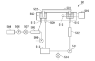
- FIG. 2 is a schematic diagram showing an example of the configuration of a chemical analysis apparatus according to an embodiment of the present invention.
- the chemical analysis apparatus 2A has a water supply tank 11A, a thermostatic bath 12A, and a hollow fiber degassing module 20A.
- the water supply tank 11A and the thermostatic bath 12A are connected to each other via a flow path 13A that forms a circulation path, and a liquid feed pump 14A is provided in the flow path 13A.
- the water supply tank 11A is connected to the flow path 13A via a water supply pump 15A.
- a supply pipe 12AA is attached to the liquid supply side of the thermostatic bath 12A, and a discharge pipe 12AB is attached to the liquid discharge side.
- the hollow fiber degassing module 20A is provided in the flow path 13A, and a vacuum pump 6 is further connected via a flow path 3c.
- pure water is supplied from the water supply tank 11A to the flow path 13A by operation of the water supply pump 15A.
- the pure water supplied to the flow path 13A is supplied to the thermostatic bath 12A and the hollow fiber degassing module 20A by the operation of the liquid feed pump 14A.
- the pure water supplied to the thermostatic bath 12A is heated to a predetermined temperature, and the pure water supplied from the thermostatic bath 12A to the hollow fiber degassing module 20A is degassed of dissolved oxygen and air bubbles by the operation of the vacuum pump 6.
- the hollow fiber degassing module 20A has a hollow fiber membrane bundle 22 in which multiple hollow fiber membranes 220 are bundled together in a blind shape with warp threads (see Figures 4(A) and 4(B)).
- the hollow fiber membrane bundle 22 may be referred to as the "hollow fiber membrane 220" below. Details of the hollow fiber membrane will be described later.
- the chemical analysis device 2A performs chemical or biochemical analysis of a sample (hereinafter, "chemical or biochemical analysis” will also be referred to as “(bio)chemical analysis”).
- This chemical analysis device 2A is configured to reduce the pressure on the outside or inside of the hollow fiber membrane, so that when the liquid passes through the inside or outside of the hollow fiber membrane, only the gas in the liquid is separated from the liquid through the wall of the hollow fiber.
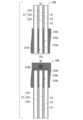
- FIG. 3 is a schematic diagram showing an example of the configuration of an internal perfusion type hollow fiber degassing module 20A provided in the chemical analysis device 2A of FIG. 2.
- constant temperature water W1 is supplied to the inside of the hollow fiber membrane 220, and the outside of the hollow fiber membrane 220 is depressurized to degas the constant temperature water W1 and produce degassed constant temperature water W2.
- the hollow fiber degassing module 20A has a housing 210 and a hollow fiber membrane 220 arranged in the internal space S1 of the housing 210.
- the housing 210 has a cylinder 211 arranged so that the axial direction L is approximately horizontal, a first lid 212A attached to one axial end 211a of the cylinder 211, and a second lid 213A attached to the other axial end 211b of the cylinder 211.
- the cylindrical body 211 has an internal space S1, and the hollow fiber membrane 220 is housed in the internal space S1.
- the cylindrical body 211 has, for example, a cylindrical shape extending in the axial direction L, and both ends of the cylindrical body 211 are open.
- the cylindrical body 211 has a first screw portion 214 where the cylindrical body 211 and the first lid portion 212A screw together, and a second screw portion 215 where the cylindrical body 211 and the second lid portion 213A screw together.
- the first lid portion 212A and the second lid portion 213A are fixed to the cylindrical body 211 by the first screw portion 214 and the second screw portion 215, respectively.
- the first lid 212A and the second lid 213A can be attached to the cylindrical body 211 by fitting, bonding, welding, etc., not limited to screwing. Either or both of the first lid 212A and the second lid 213A may be detachably attached to the cylindrical body 211.
- a seal such as an O-ring (not shown) may be provided at the attachment portion of the first lid 212A and the second lid 213A to the cylindrical body 211.
- the seal is an O-ring, it is preferable that the O-ring is disposed in an annular groove formed at the axial end 211a or the axial other end 211b of the cylindrical body 211.
- the seal can prevent liquid leakage that may occur between the cylindrical body 211 and the first lid 212A or the second lid 213A. Since the seal is not constantly in contact with liquid, the material of the seal is not particularly limited as long as the above-mentioned effect can be obtained. From the viewpoint of stain resistance, the material of the sealing portion is preferably a polyolefin resin such as polypropylene resin, the above-mentioned fluororesin, or an aromatic polyester resin such as polycarbonate resin or polyethylene terephthalate.
- the first lid portion 212A has a substantially disk-shaped first wall portion 212Aa arranged perpendicular to the axial direction L, and a substantially ring-shaped second wall portion 212Ab extending from the periphery of the first wall portion 212Aa parallel to the axial direction L.
- the first lid portion 212A is fixed to the cylindrical body 211 by the inner peripheral surface of the first lid portion 212A engaging with the outer peripheral surface of the cylindrical body 211.
- the housing 210 has a liquid supply section (first liquid supply section) 216A that connects the outside of the housing 210 with the internal space S2 of the hollow fiber membrane 220 and supplies constant temperature water W1 from the outside of the housing 210 to the internal space S2 of the hollow fiber membrane 220.
- the liquid supply section 216A is formed, for example, in the first wall section 212Aa of the first lid section 212A, and has a liquid supply port 216Aa for supplying constant temperature water W1 into the first lid section 212A.
- the liquid supply port is not particularly limited, but is, for example, a circular opening in side view formed on the central axis of the cylinder 211.
- a flow path 3a that is connected to the degassing device 3 is connected to the liquid supply section 216A.
- the connection between the liquid supply section 216A and the flow path 3a is not particularly limited, and may be performed by screwing or fitting.
- the second lid portion 213A has a substantially disk-shaped first wall portion 213Aa arranged perpendicular to the axial direction L, and a substantially ring-shaped second wall portion 213Ab extending from the periphery of the first wall portion 213Aa parallel to the axial direction L.
- the second lid portion 213A is fixed to the cylindrical body 211 by the inner peripheral surface of the second lid portion 213A engaging with the outer peripheral surface of the cylindrical body 211.
- the housing 210 has a liquid discharge section (first liquid discharge section) 217A that connects the internal space S2 of the hollow fiber membrane 220 to the outside of the housing 210 and discharges the degassed constant temperature water W2 from the internal space S2 of the hollow fiber membrane 220 to the outside of the housing 210.
- the liquid discharge section 217A is formed, for example, in the first wall section 213Aa of the second lid section 213A and has a liquid discharge port 217Aa for supplying the constant temperature water W2 to the outside.
- the liquid discharge port 217Aa is not particularly limited, but is, for example, a circular opening in side view formed on the central axis of the cylinder 211.
- the liquid discharge section 217A is connected to the flow path 3b that is connected to the reaction tank 5.
- the connection between the liquid discharge section 217A and the flow path 3b is not particularly limited, and may be made by screwing or fitting.
- the connection between the liquid discharge section 217A and the flow path 3b may also be made by a predetermined structure described later.
- the housing 210 also has a gas exhaust section (first gas exhaust section) 218A that connects the internal space S1 of the housing 210 to the outside of the housing 210 and reduces the pressure in the internal space S1 of the housing 210.
- the gas exhaust section 218A is formed in the cylindrical body 211, for example, and has a gas exhaust port 218Aa for exhausting gas G from the internal space S1. This allows moisture generated within the cylindrical body 211 to be exhausted from the cylindrical body 211 to the outside via the gas exhaust section 218A.
- a flow path 3c that is connected to the vacuum pump 6 is connected to the gas exhaust section 218A.
- the gas exhaust section 218A and the flow path 3c are connected by a predetermined structure that will be described later.
- the housing 210 has two gas exhaust sections 218A, 218A.
- the two gas exhaust sections 218A, 218A are arranged side by side in the axial direction L in the housing 210. This allows the entire internal space S1 of the housing 210 to be efficiently and evenly depressurized.
- the housing 210 may have multiple gas exhaust sections 218A, 218A, ... or may have one gas exhaust section 218A.
- the materials of the cylinder 211, first lid 212A, and second lid 213A that constitute the housing 210 are not particularly limited, but from the standpoint of ease of manufacture, chemical resistance, and stain resistance, polyolefin resins such as polypropylene resin, and aromatic polyester resins such as polycarbonate resin and polyethylene terephthalate are preferred.
- the cylinder 211, first lid 212A, and second lid 213A can be manufactured by injection molding.
- the hollow fiber membrane 220 is a hollow fiber-shaped membrane that allows gas to pass through but not liquid to pass through.
- materials for the hollow fiber membrane 220 include polyolefin resins such as polypropylene and poly(4-methylpentene-1), PTFE, amorphous fluoropolymers, tetrafluoroethylene-perfluoroalkylvinyl ether copolymers (hereinafter also referred to as PFA), tetrafluoroethylene-hexafluoropropylene copolymers (hereinafter also referred to as FEP), tetrafluoroethylene-ethylene copolymers (hereinafter also referred to as ETFE), polychlorotrifluoroethylene (hereinafter also referred to as PCTFE), polyvinylidene fluoride (hereinafter also referred to as
- the amorphous fluoropolymer (hereinafter also referred to as "Teflon (registered trademark) AF”) may be, more specifically, an amorphous fluororesin containing a copolymer with tetrafluoroethylene and perfluoro 2,2-dimethyl-1,3-dioxole as comonomers.
- Teflon (registered trademark) AF amorphous fluororesin containing a copolymer with tetrafluoroethylene and perfluoro 2,2-dimethyl-1,3-dioxole as comonomers.
- the membrane shape (sidewall shape) of the hollow fiber membrane 220 include a porous membrane, a microporous membrane, and a homogeneous membrane (non-porous membrane) that does not have porosity.
- Examples of the membrane form of the hollow fiber membrane 220 include a symmetric membrane (homogeneous membrane) in which the chemical or physical structure of the entire membrane is homogeneous, and an asymmetric membrane (heterogeneous membrane) in which the chemical or physical structure of the membrane differs depending on the part of the membrane.
- An asymmetric membrane is a membrane that has a non-porous dense layer and a porous layer. In this case, the dense layer may be formed anywhere in the membrane, such as the surface layer of the membrane or the inside of the porous membrane.
- Heterogeneous membranes also include composite membranes with different chemical structures and multi-layered membranes such as a three-layer structure.
- heterogeneous membranes using poly(4-methylpentene-1) resin have a dense layer that blocks liquids, making them particularly suitable for degassing liquids other than water, such as constant temperature water.
- a dense layer is formed on the outer surface of the hollow fibers.
- the hollow fiber membrane bundle 22 can be formed, for example, into a sheet-like material in which a plurality of hollow fiber membranes 220 are bundled in a blind shape with warp threads.
- the sheet-like material is wound to form the hollow fiber membrane bundle 22, and both ends of the hollow fiber membrane bundle 22 are fixed with a sealing material described below, thereby manufacturing the hollow fiber degassing module 20A.
- polyolefin resins such as polypropylene resin and the above-mentioned fluororesins are cited as examples of materials preferred for the warp threads.
- FIG. 4(A) is a partial cross-sectional view showing the configuration of a first sealing portion 231A provided at one axial end 211a of the cylindrical body 211 in FIG. 3, and FIG. 4(B) is a partial cross-sectional view showing the configuration of a second sealing portion 232A provided at the other axial end 211b of the cylindrical body 211 in FIG. 3.
- the hollow fiber degassing module 20A has a first sealing part 231A that seals one axial end 211a (see Figure 3) of the cylindrical body 211, and a second sealing part 232A that seals the other axial end 211b (see Figure 3) of the cylindrical body 211.
- One longitudinal end 220a of the hollow fiber membrane 220 is fixed to the first sealing part 231A, and the other longitudinal end 220b of the hollow fiber membrane 220 is fixed to the second sealing part 232A. That is, one longitudinal end 22a of the hollow fiber membrane bundle 22 is fixed to the first sealing part 231A, and the other longitudinal end 22b is fixed to the second sealing part 232A.
- the first sealing portion 231A fills the entire area except for the internal space S2 of the hollow fiber membrane 220 in a cross section perpendicular to the axial direction L of the cylindrical body 211. In other words, the first sealing portion 231A does not fill the internal space S2 of the hollow fiber membrane 220, but fills between the hollow fiber membranes 220 and between the hollow fiber membrane bundle 22 and the inner wall of the cylindrical body 211.
- the second sealing portion 232A fills the entire area except for the internal space S2 of the hollow fiber membrane 220 in a cross section perpendicular to the axial direction L of the cylindrical body 211. In other words, the second sealing portion 232A does not fill the internal space S2 of the hollow fiber membrane 220, but fills between the hollow fiber membranes 220 and between the hollow fiber membrane bundle 22 and the inner wall of the cylindrical body 211.
- the first sealing portion 231A and the second sealing portion 232A are not particularly limited, but from the standpoint of ease of manufacture, chemical resistance, and stain resistance, it is preferable that they are formed from, for example, a cured product of a curable resin composition containing an epoxy resin or a (meth)acrylic resin, or a polyolefin resin such as polyethylene or polypropylene.
- the first sealing portion 231A seals one axial end 211a of the cylinder 211 while communicating the internal space S3 of the first lid portion 212A with the internal space S2 of the hollow fiber membrane 220.
- the second sealing portion 232A seals the other axial end 211b of the cylinder 211 while communicating the internal space S4 of the second lid portion 213A with the internal space S2 of the hollow fiber membrane 220.
- the internal space S3 of the first lid portion 212A and the internal space S4 of the second lid portion 213A are partitioned from the internal space S1 of the housing 210 by the first sealing portion 231A and the second sealing portion 232A, respectively, and the internal space S3 of the first lid portion 212A, the internal space S2 of the hollow fiber membrane 220, and the internal space S4 of the second lid portion 213A are communicated in this order.
- the constant temperature water W1 supplied from the liquid supply unit 216A to the internal space S3 of the first lid unit 212A is supplied only to the internal space S2 of the hollow fiber membrane 220 and is prevented from flowing into the internal space S1 of the housing 210.
- the internal space S1 of the housing 210 is depressurized, preferably to a vacuum, by exhausting air from the gas exhaust port 218Aa by the vacuum pump 6. Then, as the constant temperature water W1 passes through the internal space S2 of the hollow fiber membrane 220, the dissolved gas and air bubbles in the constant temperature water W1 are drawn to the outside of the hollow fiber membrane 220, thereby degassing the constant temperature water W1 (degassing method).
- the degassed constant temperature water W2 flows only from the internal space S2 of the hollow fiber membrane 220 into the internal space S4 of the second lid portion 213A, and is supplied from the liquid discharge portion 217A into the reaction tank 5 of the (bio)chemical analysis portion 4A.
- the liquid contact parts with constant temperature water W1, W2 are mainly composed of first lid part 212A, first sealing part 231A, hollow fiber membrane 220, second sealing part 232A, and second lid part 213A.
- the hollow fiber degassing module 20A has one-touch joint structures 701A, 701A in the gas discharge parts 218A, 218A that connect the housing 210 and the tube member.
- the one-touch joint structures 701A, 701A are attached to the housing 210 in a sealed state such as airtightness.
- Fig. 5 is a cross-sectional view showing an example of the configuration of the one-touch joint structure 701A provided in the gas discharge section 218A of Fig. 3.
- the one-touch joint structure 701A has a joint body 701Aa fixed to the housing 210, and a tube connection part 701Ab to which a tube member T constituting the flow path 3c is detachably connected.
- the tube connection part 701Ab has a recess 701Ac provided on one end side of the joint body 701Aa in the axial direction, a seal member 701Ad accommodated in the recess 701Ac, a buckling ring 701Ae and a locking ring 701Af accommodated in the recess 701Ac and disposed on the tube insertion port side of the seal member 701Ad, a tube insertion port 701Ag, and a collar 701Ah and an opening sleeve 701Ai attached to the tube insertion port 701Ag.
- the tube member T can be attached and detached very easily.
- the end Ta of the tube member T is inserted into the one-touch joint structure 701A all the way to the innermost part of the recess 701Ac, so that the tube member T and the lock ring 701Af fit together, and the tube member T is fixed to the one-touch joint structure 701A.
- the release sleeve 701Ai is pushed toward the joint body 701Aa along the axial direction of the joint body 701Aa, so that the lock ring 701Af is released from the tube member T, and the tube member T is pulled out from the one-touch joint structure 701A.
- the one-touch joint structure refers to one in which the tube member and the joint can be attached or detached with a single operation, and is, for example, a structure in which the tube member or the joint side member can be easily attached and detached by moving the tube member or the joint side member in one direction, such as the axial direction.
- the one-touch joint structure 701A of this embodiment is not limited to the configuration shown in FIG. 5.
- the one-touch joint structure 701A only needs to have a fixing part that is fixed to the housing and a tube connection part to which a tube member is detachably connected, and to have a structure in which the tube member and the tube connection part are connected in a sealed state when the tube is attached.
- the one-touch joint structure 701A in FIG. 5 can be replaced with a lure fitting structure described later, and the one-touch joint structure and the lure fitting structure described later can be used in combination in the hollow fiber degassing module 20A.
- the hollow fiber degassing module 20A As a manufacturing method of the hollow fiber degassing module 20A, for example, a predetermined number of hollow fibers are bundled together to form the hollow fiber membrane bundle 22. At this time, an external support 234 may be used to cover the hollow fiber membrane bundle 22.
- a gas exhaust port 218Aa is provided on the peripheral wall of the cylindrical body, and a screw portion and/or an O-ring groove portion is provided at both axial ends of the cylindrical body as necessary to form the cylindrical body 211.
- one axial end 211a of the cylindrical body 211 and one longitudinal end 22a of the hollow fiber membrane bundle 22 are fixed with a sealing material to form a first sealing portion 231A
- the other axial end 211b of the cylindrical body 211 and the other longitudinal end 22b of the hollow fiber membrane bundle 22 are fixed with a sealing material to form a second sealing portion 232A.
- the end faces of the first sealing portion 231A and the second sealing portion 232A are cut.
- the first lid portion 212A is attached to one axial end portion 211a of the cylindrical body 211, and the second lid portion 213A is attached to the other axial end portion 211b of the cylindrical body 211 to form the housing 210.
- the one-touch joint structures 701A, 701A are fixed to the gas exhaust ports 218Aa, 218Aa of the cylindrical body 211 by screwing or adhesive. This completes the manufacture of the hollow fiber degassing module 20A having the housing 210 and the hollow fiber membrane 220.
- the housing 210 has a gas discharge section 218A that connects the internal space S1 of the housing 210 to the outside of the housing 210 and reduces the pressure of the internal space S1 of the housing 210, and the gas discharge section 218A has a one-touch joint structure 701A that connects the housing 210 to the tube member, so that the water liquefied in the internal space S1 easily flows into the gas discharge section 218A by gravity and is discharged from the gas discharge section 218A to the outside.
- the one-touch joint structure 701A allows the tube member to be easily removed, excessive stress is not applied to the one-touch joint structure 701A when the water accumulated in the internal space S1 or the gas discharge section 218A is periodically removed, and tensile fatigue failure at the connection between the housing 210 and the one-touch joint structure 701A can be prevented.
- compression fatigue failure and bending fatigue failure can be prevented by easily attaching the tube member. Therefore, deterioration of the connection between the housing 210 and the one-touch joint structure 701A is suppressed to prevent gas leakage, and the original performance of the hollow fiber degassing module 20A can be maintained for a long period of time.
- the inner surface of the tube member is not scraped due to friction between the one-touch joint structure 701A and the tube member, and the inclusion of dust (particles) and the like can be prevented for a long period of time by maintaining good sealing between the one-touch joint structure 701A and the tube.
- FIG. 6 is a diagram showing a modified example of the internal perfusion type hollow fiber degassing module 20A of FIG. 3.
- the hollow fiber degassing module 20AA of FIG. 6 differs from the internal perfusion type hollow fiber degassing module 20A of FIG. 3 in that the liquid supply section 216A and the liquid discharge section 217A each have one-touch joint structures 702A, 702A that connect the housing 210 and the tube member.
- the one-touch joint structure 702A can also be replaced with a lure fitting structure described later, and the one-touch joint structure and the lure fitting structure described later can also be used in combination in the hollow fiber degassing module 20AA.
- the inner surface of the tube member is not scraped off by friction between the one-touch joint structure 702A and the tube member, as compared to conventional bamboo shoot joints, and it is possible to prevent contamination of the liquid side, i.e., the constant temperature water side, with dirt (particles) for a long period of time.
- the one-touch joint structures 702A, 702A allow the tube member to be easily attached and detached, it is possible to prevent fatigue failure at the connection between the housing 210 and the one-touch joint structure 702A, and it is possible to prevent water leakage from that part.
- FIG. 7 is a diagram showing an external perfusion type hollow fiber degassing module.
- the chemical analysis device 2A may have an external reflux type hollow fiber degassing module 20B instead of the internal reflux type hollow fiber degassing module shown in FIG. 3.
- constant temperature water W1 is supplied to the outside of the hollow fiber membrane 220 and the inside of the hollow fiber membrane 220 is depressurized, thereby degassing the constant temperature water W1 and producing degassed constant temperature water W2.
- the hollow fiber degassing module 20B has a housing 210 and a hollow fiber membrane 220 arranged in the internal space S1 of the housing 210.
- the housing 210 has a cylinder 211 arranged so that the axial direction L is approximately vertical, a third lid 212B attached to the axial lower end 211c of the cylinder 211, and a fourth lid 213B attached to the axial upper end 211d of the cylinder 211.
- the cylindrical body 211 has an internal space S1, and the hollow fiber membrane 220 is housed in the internal space S1.
- the cylindrical body 211 has, for example, a cylindrical shape extending in the axial direction L, and both ends of the cylindrical body 211 are open.
- the cylindrical body 211 has a first screw portion 214 at which the cylindrical body 211 and the third lid portion 212B screw together, and a second screw portion 215 at which the cylindrical body 211 and the fourth lid portion 213B screw together.
- the third lid portion 212B and the fourth lid portion 213B are fixed to the cylindrical body 211 by the first screw portion 214 and the second screw portion 215, respectively.
- the third lid portion 212B and the fourth lid portion 213B can be attached to the cylindrical body 211 by fitting, bonding, welding, etc., not limited to screwing. Either or both of the third lid portion 212B and the fourth lid portion 213B may be detachably attached to the cylindrical body 211.
- a seal portion such as an O-ring (not shown) may be provided at the attachment portion of the third lid portion 212B and the fourth lid portion 213B to the cylindrical body 211.
- the seal portion is composed of an O-ring, it is preferable that the O-ring is disposed in a ring-shaped groove portion or the like formed in the axial lower end portion 211c or the axial upper end portion 211d of the cylindrical body 211.
- the seal portion can prevent liquid leakage that may occur between the cylindrical body 211 and the third lid portion 212B or the fourth lid portion 213B. Since the seal portion is not constantly in contact with liquid, the material of the seal portion is not particularly limited as long as the above-mentioned action and effect can be obtained. From the viewpoint of stain resistance, the material of the sealing portion is preferably a polyolefin resin such as polypropylene resin, the above-mentioned fluororesin, or an aromatic polyester resin such as polycarbonate resin or polyethylene terephthalate.
- the third lid portion 212B may have a substantially disk-shaped first wall portion 212Ba arranged perpendicular to the axial direction L, and a substantially ring-shaped second wall portion 212Bb extending parallel to the axial direction L from the periphery of the first wall portion 212Ba.
- the third lid portion 212B is fixed to the cylindrical body 211 by the inner peripheral surface of the third lid portion 212B engaging with the outer peripheral surface of the cylindrical body 211.
- the fourth lid portion 213B may have a substantially disk-shaped first wall portion 213Ba arranged perpendicular to the axial direction L, and a substantially ring-shaped second wall portion 213Bb extending parallel to the axial direction L from the periphery of the first wall portion 213Ba.
- the fourth lid portion 213B is fixed to the cylindrical body 211 by the inner peripheral surface of the fourth lid portion 213B engaging with the outer peripheral surface of the cylindrical body 211.
- the housing 210 has a liquid supply section (second liquid supply section) 216B that connects the outside of the housing 210 to the internal space S1 of the housing 210 and supplies constant temperature water W1 from the outside of the housing 210 to the internal space S1 of the housing 210.
- the liquid supply section 216B is provided in the cylindrical body 211.
- the liquid supply section 216B is formed, for example, in the cylindrical body 211 and has a liquid supply port 216Ba for supplying the constant temperature water W1 into the cylindrical body 211.
- the liquid supply port is not particularly limited, but is a circular opening in side view formed at the axial lower end 211c of the cylindrical body 211 or in its vicinity.
- a flow path 3a connected to the degassing device 3 is connected to the liquid supply port 216Ba.
- the liquid supply port 216Ba and the flow path 3a are preferably connected by a predetermined structure described below. However, this is not limiting, and the connection between the liquid supply port 216Ba and the flow path 3a may be made in a form other than the specified structure described below.
- the housing 210 has a liquid discharge section (second liquid discharge section) 217B that connects the internal space S1 of the housing 210 to the outside of the housing 210 and discharges the degassed constant temperature water W2 from the internal space S1 of the housing 210 to the outside of the housing 210.
- the liquid discharge section 217B is provided in the fourth lid section 213B.
- the liquid discharge section 217B is formed, for example, in the first wall section 213Ba of the fourth lid section 213B and has a liquid discharge port 217Ba for supplying the constant temperature water W2 to the outside.
- the liquid discharge port 217Ba is not particularly limited, but is, for example, a circular opening in a side view formed on the central axis of the cylindrical body 211.
- the liquid discharge port 217Ba is connected to a flow path 3b that is connected to the reaction tank 5.
- the liquid discharge port 217Ba and the flow path 3b are preferably connected by a predetermined structure described later. However, this is not limiting, and the connection between the liquid outlet 217Ba and the flow path 3b may be made in a form other than the specified structure described below.
- the housing 210 has a gas discharge section (second gas discharge section) 218B for connecting the internal space S2 of the hollow fiber membrane 220 to the outside of the housing 210 and reducing the pressure of the internal space S2 of the hollow fiber membrane 220.
- the gas discharge section 218B is formed, for example, in the first wall section 212Ba of the third lid section 212B and has a gas discharge port 218Ba for discharging the gas G in the internal space S2.
- the gas discharge section 218B is provided in the third lid section 212B. It is preferable that the gas discharge section 218B is provided in the third lid section 212B.
- the housing 210 also has a central pipe 233 arranged inside the cylindrical body 211 so as to be parallel to the axial direction of the cylindrical body 211, and an external support 234 that is approximately coaxial with the central pipe 233 and arranged between the cylindrical body 211 and the central pipe 233.
- the central pipe 233, external support 234, and cylindrical body 211 are arranged in this order from the center to the outside in the radial direction of the housing 210.
- a hollow fiber membrane bundle 22 is disposed between the central pipe 233 and the external support 234.
- the materials of the cylinder 211, the third lid portion 212B and the fourth lid portion 213B that constitute the housing 210, and the material of the hollow fiber membrane 220 can be the same as those of the internal perfusion type hollow fiber degassing module 20A.
- the hollow fiber membrane bundle 22 can be formed, for example, as a sheet-like material in which a number of hollow fiber membranes 220 are bundled in a blind shape with warp threads.
- the sheet-like material can be bundled into a cylindrical shape to form a hollow fiber membrane bundle, and both ends of the cylindrically bundled hollow fiber membrane bundle can be fixed with a sealing material to manufacture the hollow fiber degassing module 20B.
- the material of the warp threads can be the same as that of the internal perfusion type hollow fiber degassing module 20A.
- One longitudinal end 220a of the hollow fiber membrane 220 is fixed to the third sealing portion 231B, and the other longitudinal end 220b of the hollow fiber membrane 220 is fixed to the fourth sealing portion 232B. That is, one longitudinal end 22a of the hollow fiber membrane bundle 22 is fixed to the third sealing portion 231B, and the other longitudinal end 22b is fixed to the fourth sealing portion 232B.
- the third sealing portion 231B fills the entire area except for the internal space S2 of the hollow fiber membrane 220 in a cross section perpendicular to the axial direction L of the cylindrical body 211. In other words, the third sealing portion 231B does not fill the internal space S2 of the hollow fiber membrane 220, but fills between the hollow fiber membranes 220 and between the hollow fiber membrane bundle 22 and the inner wall of the cylindrical body 211.
- the fourth sealing portion 232B fills the entire area except for the internal space S2 of the hollow fiber membrane 220 in a cross section perpendicular to the axial direction L of the cylindrical body 211. In other words, the fourth sealing portion 232B does not fill the internal space S2 of the hollow fiber membrane 220, but fills between the hollow fiber membranes 220 and between the hollow fiber membrane bundle 22 and the inner wall of the cylindrical body 211.
- the fourth sealing portion 232B has a communication port 232Ba that communicates the internal space S1 of the housing 210 with the internal space S4 of the fourth lid portion 213B.
- the fourth sealing portion 232B also blocks the other longitudinal end portion 220b of the hollow fiber membrane 220. Therefore, the internal space S2 of the hollow fiber membrane 220 does not communicate with the internal space S4 of the fourth lid portion 213B.
- the materials for the third sealing section 231B and the fourth sealing section 232B can be the same as those for the internal perfusion type hollow fiber degassing module 20A.
- the third sealing portion 231B seals the axial lower end 211c of the cylinder 211 while communicating the internal space S3 of the third lid portion 212B with the internal space S2 of the hollow fiber membrane 220.
- the fourth sealing portion 232B seals the axial upper end 211d of the cylinder 211 while blocking the internal space S4 of the fourth lid portion 213B with the internal space S2 of the hollow fiber membrane 220.
- the internal space S3 of the third lid portion 212B and the internal space S1 of the housing 210 are partitioned by the third sealing portion 231B, the internal space S4 of the fourth lid portion 213B and the internal space S1 of the housing 210 are in communication, and the internal space S3 of the third lid portion 212B and the internal space S2 of the hollow fiber membrane 220 are in communication.
- the constant temperature water W1 supplied from the liquid supply unit 216B to the internal space S1 of the housing 210 is supplied only to the internal space S4 of the fourth lid portion 213B and is prevented from flowing into the internal space S3 of the third lid portion 212B.
- the internal space S2 of the hollow fiber membrane 220 is depressurized, preferably to a vacuum, by exhausting air from the gas exhaust port 218Ba by the vacuum pump 6. Then, as the constant temperature water W1 passes through the internal space S1 of the housing 210, the dissolved gas and air bubbles in the constant temperature water W1 are drawn into the inside of the hollow fiber membrane 220, thereby degassing the constant temperature water W1.
- the degassed constant temperature water W2 flows only from the internal space S1 of the housing 210 into the internal space S4 of the fourth lid portion 213B, and is supplied from the liquid discharge portion 217B into the reaction tank 5 of the (bio)chemical analysis portion 4A.
- the liquid contact parts with constant temperature water W1, W2 are mainly composed of third sealing part 231B, hollow fiber membrane 220, fourth sealing part 232B, and fourth lid part 213B.
- the gas discharge section 218B has a one-touch joint structure 701B that connects the housing 210 and the tube member.
- the one-touch joint structure 701B is attached to the housing 210 in a sealed state, such as airtightness.
- the second liquid supply section 216B and the second liquid discharge section 217B each have a one-touch joint structure 702B, 702B that connects the housing 210 and the tube member.
- the one-touch joint structures 702B, 702B are attached to the housing 210 in a sealed state, such as watertightness.
- the structure of the one-touch joint structures 701B, 702B is similar to the one-touch joint structure 701A ( Figure 5).
- the one-touch joint structures 701B and 702B of this embodiment are not limited to the configuration shown in FIG. 5, and may have a fixing part that is fixed to the housing and a tube connection part to which the tube member is detachably connected, and may have a structure in which the tube member and the tube connection part are connected in a sealed state when the tube is attached.
- a sheet-like material in which a plurality of hollow fiber membranes 220 are bundled in a blind shape with warp threads is wound around a cylindrical central pipe 233 and bundled into a cylindrical shape to form the hollow fiber membrane bundle 22.
- an external support 234 may be used to cover the hollow fiber membrane bundle 22.
- a liquid supply port 216Ba is provided on the peripheral wall of the cylindrical body, and a screw portion and/or an O-ring groove portion are provided at both axial ends of the cylindrical body as necessary to form the cylindrical body 211.
- one axial end of the cylindrical body 211 and one longitudinal end 22a of the hollow fiber membrane bundle 22 are fixed with a sealing material to form the third sealing portion 231B.
- the other axial end of the cylindrical body 211 and the other longitudinal end 22b of the hollow fiber membrane bundle 22 are fixed with a sealing material to form the fourth sealing portion 232B.
- only the third sealing portion 231B or the end faces of the third sealing portion 231B and the fourth sealing portion 232B are cut.
- the third lid portion 212B is attached to the one axial end of the cylindrical body 211 on which the third sealing portion 231B is provided, and the fourth lid portion 213B is attached to the other axial end of the cylindrical body 211 on which the fourth sealing portion 232B is provided to form the housing 210, thereby manufacturing the hollow fiber degassing module 20B having the housing 210 and the hollow fiber membranes 220.
- the hollow fiber degassing module 20B has a gas exhaust section 218B that connects the internal space S2 of the hollow fiber membrane 220 to the outside of the housing 210 and reduces the pressure in the internal space S2 of the hollow fiber membrane 220. Since the gas exhaust section 218B is provided in the housing 210, the water liquefied in the internal space S2 is exhausted to the outside from the gas exhaust section 218B. Therefore, water is less likely to accumulate in the internal space S2 of the hollow fiber membrane 220, the internal space S3 of the third lid section 212B, and the gas exhaust section 218B, and the original good degassing performance can be maintained even with long-term continuous use.
- the humidity of the internal space S2 of the hollow fiber membrane 220 and the gas exhaust section 218B can be kept low, bacteria and the like are less likely to occur even when opened after operation, and the proliferation of bacteria and the like in the internal space S2 of the hollow fiber membrane 220, the internal space S3 of the third lid section 212B, and the gas exhaust section 218B can be suppressed.
- the one-touch joint structure 701B allows the tube member to be easily removed, excessive stress is not applied to the one-touch joint structure 701B when the water accumulated in the internal space S3 or the gas discharge section 218B is periodically removed, and tensile fatigue failure at the connection between the housing 210 and the one-touch joint structure 701B can be prevented.
- the one-touch joint structure 701B when inserting a tube member into the one-touch joint structure 701B, compression fatigue failure and bending fatigue failure can be prevented by easily attaching the tube member. Therefore, deterioration of the connection between the housing 210 and the one-touch joint structure 701B is suppressed to prevent gas leakage, and the original performance of the hollow fiber degassing module 20B can be maintained for a long period of time.
- the inner surface of the tube is not scraped due to friction between the one-touch joint structure 701B and the tube member, and the inclusion of dust (particles) and the like can be prevented for a long period of time by maintaining good sealing between the one-touch joint structure 701B and the tube member.
- the one-touch joint structure 701B allows the tube member to be easily attached and detached, fatigue failure at the connection between the housing 210 and the one-touch joint structure 702B can be prevented, making it possible to prevent water leakage from that portion.
- the one-touch joint structures 701B and 702B can be replaced with a lure fitting structure described below, and the one-touch joint structure and the lure fitting structure described below can be used in combination in the hollow fiber degassing module 20B.
- Fig. 9 is a side view showing a modification of the hollow fiber degassing module 20B in Fig. 7.
- the structure of the hollow fiber degassing module 20D in Fig. 9 is basically the same as that of the hollow fiber degassing module 20B, except that the structures of the second liquid supply section 216B, the second liquid discharge section 217B, and the gas discharge section 218B are different.
- the hollow fiber degassing module 20D has a liquid supply section (second liquid supply section) 216D, a liquid discharge section (second liquid discharge section) 217D, and a gas discharge section 218D.
- the hollow fiber degassing module 20D has a one-touch joint structure 701B in the gas discharge section 218D that connects the housing 210D to the tube member.
- the hollow fiber degassing module 20D also has one-touch joint structures 702B, 702B in the liquid supply section 216D and the liquid discharge section 217D that connect the housing 210D to the tube member.
- the housing 210D has an extension section 210Da that is integral with the housing 210D and extends outward from the housing 210D to which the one-touch joint structure 701B is attached, and a rib section 210Db that is provided on the extension section 210Da.
- a metal ring member 210Dc and a nut 210Dd fixed to the ring member 210Dc are arranged at the end of the extension section 210Da, and the one-touch joint structure 701B is arranged inside the nut 210Dd.
- the housing 210D has extensions 210De, 210De that are integral with the housing 210D and extend outward from the housing 210D to which one-touch joint structures 702B, 702B are attached, and ribs 210Df, 210Df that are provided on the extensions 210De, 210De.
- a metal ring member 210Dg and a nut 210Dh fixed to the ring member 210Dg are disposed at the end of the extension 210De, and the one-touch joint structure 701B is disposed inside the nut 210Dh.
- the housing 210D has an extension portion 210Da which is formed integrally with the housing 210D, extends outward from the housing 210D and has one-touch joint structure 701B attached thereto, and extension portions 210De, 210De which are formed integrally with the housing 210D, extend outward from the housing 210D and have one-touch joint structures 702B, 702B attached thereto.
- This improves the strength of the connection between the housing 210D and the one-touch joint structure 701B, preventing fatigue failure and reliably preventing gas and water leakage.
- the housing 210D has a rib portion 210Db provided on the extension portion 210Da and rib portions 210Df, 210Df provided on the extension portions 210De, 210De, which further improves the strength of the extension portions 210Da, 210De, 210De, and more reliably prevents gas and water leakage.
- the extension and rib portions are provided in the hollow fiber degassing module 20D, which is an external perfusion type, but this is not limiting, and the extension and rib portions may also be provided in the hollow fiber degassing module 20D, which is an internal reflux type.
- the extension and rib portions may be provided in the gas discharge portion 218A, the liquid supply portion 216A, and the liquid discharge portion 217A of the hollow fiber degassing module 20B in Figure 3.
- the one-touch joint structures 701B and 702B can be replaced with a lure fitting structure, which will be described later, and the one-touch joint structure and the lure fitting structure, which will be described later, can be used in combination in the hollow fiber degassing module 20D.
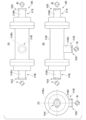
- Fig. 10(A) is a top view
- Fig. 10(B) is a side view
- Fig. 10(C) is a front view showing another modification of the hollow fiber degassing module 20B shown in Fig. 7.
- the structure of the hollow fiber degassing module 20E in Figs. 10(A) to 10(C) is basically the same as that of the hollow fiber degassing module 20B, except that the structures of the second liquid supply section 216B, the second liquid discharge section 217B, and the gas discharge section 218B are different.
- the hollow fiber degassing module 20E has a liquid supply section (second liquid supply section) 216E, a liquid discharge section (second liquid discharge section) 217E, and a gas discharge section 218E.
- the hollow fiber degassing module 20E has a luer fitting joint structure 701E in the gas discharge section 218E that connects the housing 210E to the tube member.
- the hollow fiber degassing module 20E also has luer fitting joint structures 702E, 702E in the liquid supply section 216E and the liquid discharge section 217E that connect the housing 210E to the tube member.
- the housing 210E in the gas discharge section 218E, has an extension section 210Ea that is integral with the housing 210E and extends outward from the housing 210E to form a lure fitting joint structure 701E.
- the housing 210E in the liquid supply section 216E and the liquid discharge section 217E, the housing 210E has extension sections 210Eb, 210Eb that are integral with the housing 210E and extend outward from the housing 210E to form lure fitting joint structures 702E, 702E.
- the lure fitting joint structure 701E constitutes, for example, a male terminal of the lure fitting joint structure, and engages with a female terminal provided at the end of the tube member to fix the tube member to the housing 210E.
- the configuration of the lure fitting joint structure 702E is the same as the configuration of the lure fitting joint structure 701E.
- the tube member T can be attached and detached very easily, as in the case of a one-touch joint structure.
- the lure fitting joint structure 701E constituting the male terminal is inserted into the end of the tube member constituting the female terminal and rotated, so that the male and female terminals engage with each other, and the tube member is fixed to the lure fitting joint structure 701E.
- the end of the tube member constituting the female terminal is rotated in the opposite direction to that when attached, so that the male and female terminals are released from engagement, and the tube member and the lure fitting joint structure 701E are separated.
- the lure fitting joint structure refers to one in which the tube member and joint can be attached or detached with a single operation, and is a structure in which the tube member can be easily attached and detached with respect to the male terminal on the housing side by rotating the female terminal to which the tube member is attached in one direction, such as the circumferential direction around the axis.
- the housing 210E has an extension portion 210Ea that is integral with the housing 210E, extends outward from the housing 210E, and has the luer fitting joint structure 701E attached thereto, and extension portions 210Eb, 210Eb that are integral with the housing 210E, extend outward from the housing 210E, and have the luer fitting joint structures 702E, 702E attached thereto.
- This improves the strength of the connection between the housing 210E and the luer fitting joint structures 701E, 702E, and reliably prevents gas and water leakage.
- the housing 210E may have a rib portion provided on the extension portion 210Ea and a rib portion provided on the extension portions 210Eb, 210Eb. This further improves the strength of the extension portions 210Ea, 210Eb, 210Eb, and makes it possible to more reliably prevent gas leakage and water leakage.
- the housing 210C also has a gas exhaust section (first gas exhaust section) 218C that connects the internal space S5 of the housing 210C to the outside of the housing 210C and reduces the pressure in the internal space S5 of the housing 210C.
- the gas exhaust section 218C is formed in, for example, the cylindrical body 211C and has a gas exhaust port 218Ca for exhausting gas G in the internal space S5.
- the gas exhaust section 218C is provided in the housing 210C.
- the gas exhaust section 218C is preferably provided on the peripheral wall of the cylindrical body 211C.
- the gas exhaust section 218C, 218C has a one-touch joint structure 701C, 701C that connects the housing 210C and the tube member.
- the one-touch joint structure 701C, 701C is attached to the housing 210C in an airtight or other sealed state.
- the one-touch joint structure can also be replaced with a luer fitting joint structure, and the one-touch joint structure and the luer fitting structure can also be used in combination in the hollow fiber degassing module 20C.
- FIG. 12 is a diagram showing another modified example of the internal perfusion type hollow fiber degassing module of FIG. 3.
- the hollow fiber degassing module 20C of FIG. 12 differs from the internal perfusion type hollow fiber degassing module 20C of FIG. 11 in that the liquid supply section 216C and the liquid discharge section 217C each have one-touch joint structures 702C, 702C that connect the housing 210C and the tube member.
- the one-touch joint structure can also be replaced with a luer fitting joint structure, and the one-touch joint structure and the luer fitting structure can also be used in combination in the hollow fiber degassing module 20C.
- the inner surface of the tube member is not scraped off by friction between the one-touch joint structure 702C and the tube member, compared to conventional bamboo shoot joints, and it is possible to prevent contamination of the liquid side, i.e., the constant temperature water side, with dirt (particles) for a long period of time.
- the one-touch joint structures 702C, 702C allow the tube member to be easily attached and detached, it is possible to prevent fatigue failure at the connection between the housing 210C and the one-touch joint structure 702C, and it is possible to prevent water leakage from that part.
- Fig. 13 is a block diagram showing a modification of the chemical analysis apparatus 2A in Fig. 1.
- the chemical analysis apparatus 2D in Fig. 13 differs from the chemical analysis apparatus 2A in that it does not have a circulation path and has a liquid-borne particle counter.
- the chemical analysis device 2D has a water supply tank 11A, a thermostatic bath 12A, and a hollow fiber degassing module 20A.
- the water supply tank 11A and the thermostatic bath 12A are connected to each other via a flow path 18A, and a liquid feed pump 14A is provided in the flow path 18A.
- the water supply tank 11A is connected to the flow path 18A via a water supply pump 15A.
- a discharge pipe 12AB is attached to the liquid discharge side of the thermostatic bath 12A.
- the hollow fiber degassing module 20A is provided in the flow path 18A, and is further connected to a vacuum pump 6 via a flow path 3c.
- the liquid-borne particle meter 19A is disposed downstream of the hollow fiber degassing module 20A in the flow path 18A, and a supply pipe 19AA is attached to the liquid supply side of the liquid-borne particle meter 19A, and a discharge pipe 19AB is attached to the liquid discharge side.
- the pure water heated to a predetermined temperature in the thermostatic bath 12A is supplied to the hollow fiber degassing module 20A by the operation of the liquid feed pump 14A.
- Dissolved oxygen and air bubbles are degassed from the pure water supplied to the hollow fiber degassing module 20A by the operation of the vacuum pump 6.
- the pure water is supplied from the water supply tank 11A to the flow path 13A by the operation of the water supply pump 15A.
- the pure water discharged from the hollow fiber degassing module 20A is supplied to the liquid-borne particle meter 19A, and the liquid-borne particle meter 19A measures the particles in the pure water.
- the hollow fiber degassing module 20A may be provided in the chemical analysis device 2D.
- the hollow fiber degassing modules 20B, 20C, 20D, and 20E may be provided in the chemical analysis device 2D.
- FIG. 14 is a block diagram that illustrates another modified example of the chemical analysis apparatus 2A in FIG.
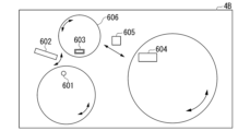
- the chemical analysis device 2B includes a reaction disk 401, a reaction vessel 402, a reaction tank 403, and a circulation pump 306.
- the reaction vessel 402 attached to the circumference of the circular reaction disk 401 is immersed in a liquid held in a similarly circular reaction tank 403.
- the liquid in the reaction tank 403 is constantly circulated by a circulation pump 306 installed between a discharge pipe 404 and a supply pipe 405, and the temperature is controlled by controlling the heater 307 to be on/off.
- the path including the circulation pump 306 and the heater 307 between the discharge pipe 404 and the supply pipe 405 constitutes a hot water circulation path. This keeps the reaction liquid held inside the reaction vessel 402 at an optimum temperature for reaction (e.g., 37° C.).
- the hot water circulation flow path may be provided with a cooling unit 308 for cooling the constant temperature water in the reaction tank 403 when the temperature of the constant temperature water becomes too high.
- a water supply tank 309 and a water supply pump 310 are connected to the hot water circulation flow path, and the supply of pure water from the water supply tank 309 is controlled by the water supply pump 310 and the water supply valve 311.
- a waste liquid valve 312 is provided in the hot water circulation flow path, and the constant temperature water is discharged as waste liquid outside the flow path when the high temperature water circulating in the reaction tank 403 is replaced.
- a degassing device 313 having a hollow fiber degassing module 20A or 20B is provided in the hot water circulation flow path, and dissolved gas in the constant temperature water supplied to the degassing device 313 is degassed by the operation of a vacuum pump 314.
- a beam of light irradiated from a light source lamp 315 passes through a reaction liquid, which is a mixture of a sample and a reagent held in a reaction vessel 402, and the transmitted light is measured by a multi-wavelength photometer 316, thereby performing qualitative and quantitative analysis of specific components in the sample.
- FIG. 15 is a block diagram showing another modified example of the chemical analysis system of FIG. 1.
- the chemical analysis apparatus 2C includes a reaction disk 501, a reaction vessel 502, a reaction tank 503, a water supply tank 504, and a water supply pump 506.
- the reaction vessel 502 attached to the circumference of the circular reaction disk 501 is immersed in constant temperature water held in a similarly circular reaction tank 503.
- the reaction tank 503 is supplied with constant temperature water from the water supply tank 504.
- a degassing device 505 having a hollow fiber degassing module 20A or 20B is provided on the flow path between the water supply tank 504 and the reaction tank 503, and the supply of constant temperature water is controlled by a water supply pump 506 and a water supply valve 507.
- the dissolved gas in the constant temperature water supplied to the degassing device 505 is degassed by the operation of a vacuum pump 508, and is supplied to the reaction tank 503 from a supply pipe 517.
- the constant temperature water in the reaction tank 503 is constantly circulated by a circulation pump 511 installed between the discharge pipe 509 and the supply pipe 510, and the temperature is controlled by the on/off control of a heater 512.
- the path including the circulation pump 511 and the heater 512 between the discharge pipe 509 and the supply pipe 510 constitutes a hot water circulation path. This keeps the reaction liquid held inside the reaction vessel 502 at an optimum temperature for the reaction (e.g. 37°C).
- the hot water circulation flow path may be provided with a cooling unit 513 for cooling the constant temperature water in the reaction tank 503 if the temperature of the constant temperature water becomes too high.
- the hot water circulation flow path is also provided with a waste liquid valve 514, which discharges the constant temperature water from the flow path as waste liquid when replacing the constant temperature water circulating in the reaction tank 503.
- a beam of light emitted from a light source lamp 515 passes through a reaction solution made by mixing a sample and a reagent held in a reaction vessel 502, and the transmitted light is measured by a multi-wavelength photometer 516, thereby performing qualitative and quantitative analysis of specific components in the sample.
- FIG. 16 is a block diagram that illustrates a modified example of the (bio)chemical analysis section 4A in FIG.
- the (bio)chemical analysis unit 4B may have a specimen container 601, a specimen dispensing mechanism 602, a reaction container 603, a reagent container 604, and a reagent dispensing mechanism 605.
- a specimen sent from the specimen container 601 to the reaction container 603 via the specimen dispensing mechanism 602 and a reagent sent from the reagent container 604 to the reaction container 603 via the reagent dispensing mechanism 605 can be mixed and stirred.
- the reaction container 603 is kept at a constant temperature by constant temperature water stored in a reaction tank 606.
- a degassing device (not shown) having a hollow fiber degassing module 20A or 20B is provided on a flow path that supplies constant temperature water to the reaction tank 606, and the supply of constant temperature water is controlled.
- the chemical analysis device of the above embodiment may also have a control unit (not shown) that is configured with an information processing device having a CPU, memory, I/O, microcomputer, latches, etc., and programs and data for automatic analysis and diagnosis stored in memory.
- a control unit configured with an information processing device having a CPU, memory, I/O, microcomputer, latches, etc., and programs and data for automatic analysis and diagnosis stored in memory.
- the CPU can process or centrally control the information required for the operation of the chemical analysis device and the analysis operation.
- ⁇ Preparation of hollow fiber degassing module> A plurality of internal perfusion-type hollow fiber degassing modules having a structure similar to that of the hollow fiber degassing module in Fig. 3, or external perfusion-type hollow fiber degassing modules having a structure similar to that of the hollow fiber degassing module in Fig. 7 were fabricated.
- the joint structures in the liquid supply section/gas supply section and gas discharge section shown in Table 2 were used, and the connection forms between the housing and the joint structures in the liquid supply section/gas supply section and gas discharge section were as shown in Table 1.
- each hollow fiber degassing module The material of the hollow fiber in each hollow fiber degassing module, the model of the hollow fiber degassing module, the name of the manufacturer, the perfusion method, and the connection form between the housing and the joint structure are shown in Table 1.
- Table 1 “screwed” refers to the male thread of the joint structure being screwed into the female thread of the housing, and “welded” refers to the joint structure (e.g., the bamboo shoot part) being joined to the housing by melting the resin.
- screwd (with ribs) refers to the male thread of the joint structure being screwed into the female thread provided on the ribbed extension part of the housing.
- PP lure fitting joint structure made of polypropylene
- one-touch refers to a one-touch joint structure
- bamboo shoot refers to a bamboo shoot joint structure made of polypropylene
- bamboo shoot refers to a bamboo shoot joint structure made of metal.
- Example 1 An internal circulation type hollow fiber degassing module A was prepared, in which the joint structures in the liquid supply section/gas supply section and gas discharge section were Luer fitting joint structures, and the connections between the housing and the joint structures in the liquid supply section/gas supply section and gas discharge section were screwed.
- Example 2 Internal reflux type/external perfusion type hollow fiber degassing modules E to H were prepared in the same manner as in Example 1, except that the joint structures in the liquid supply unit/gas supply unit and gas discharge unit, and the connection forms between the housings and the joint structures in the liquid supply unit/gas supply unit and gas discharge unit were changed to those shown in Tables 1 and 2.
- ⁇ Test method 1 1-month evaluation of 5°C storage durability test> (1)
- a chemical analyzer having the same configuration as the chemical analyzer shown in FIG. 1 was used to connect the hollow fiber degassing modules of each of the Examples and Comparative Examples with the joint structures shown in Table 2. Pure water was circulated (flow rate: 500 mL/min) and a vacuum pump (ULVAC, Inc., "DAP-6D", 10 kPa (abs)) was operated to perform degassing for 22 hours.
- the female terminal on the tube member side was inserted into the male terminal on the housing side while rotating and fixed.
- the female terminal on the tube member side was rotated in the opposite direction and removed.
- the tube member was inserted into the one-touch joint structure and fixed.
- the release sleeve was pressed in the axial direction and the tube member was removed.
- the tube member was screwed into the bamboo shoot joint structure and fixed with a hose band (metal ring).
- the hose band (metal ring) was removed, and the tube member was removed from the bamboo shoot joint while twisting it.
- ⁇ Test method 2 Evaluation of one-month storage durability test at 25°C> The test was carried out and evaluated in the same manner as in Test Method 1, except that the temperature of the thermostatic bath (manufactured by AS ONE Corporation, "OF-600S”) was changed to 25° C. The results are shown in Table 3.
- ⁇ Test method 3 Evaluation of one-month storage durability test at 40°C> The test was carried out and evaluated in the same manner as in Test Method 1, except that the temperature of the thermostatic bath (manufactured by AS ONE Corporation, "OF-600S”) was changed to 40° C. The results are shown in Table 4.
- Comparative Examples 1 to 4 and 7 to 10 there were more than 1,000 particles of dust (particle size 0.1 ⁇ m or more) generated from the tube members.
- the strength of the joint structure in at least one of the liquid supply section, liquid discharge section, and gas discharge section was poor.
Landscapes
- Chemical & Material Sciences (AREA)
- Chemical Kinetics & Catalysis (AREA)
- Life Sciences & Earth Sciences (AREA)
- Water Supply & Treatment (AREA)
- Engineering & Computer Science (AREA)
- Hydrology & Water Resources (AREA)
- Organic Chemistry (AREA)
- Environmental & Geological Engineering (AREA)
- Analytical Chemistry (AREA)
- Pathology (AREA)
- Immunology (AREA)
- General Physics & Mathematics (AREA)
- General Health & Medical Sciences (AREA)
- Biochemistry (AREA)
- Physics & Mathematics (AREA)
- Health & Medical Sciences (AREA)
- Degasification And Air Bubble Elimination (AREA)
- Separation Using Semi-Permeable Membranes (AREA)
Priority Applications (1)
| Application Number | Priority Date | Filing Date | Title |
|---|---|---|---|
| JP2025549650A JPWO2025089011A1 (https=) | 2023-10-26 | 2024-10-04 |
Applications Claiming Priority (2)
| Application Number | Priority Date | Filing Date | Title |
|---|---|---|---|
| JP2023184019 | 2023-10-26 | ||
| JP2023-184019 | 2023-10-26 |
Publications (1)
| Publication Number | Publication Date |
|---|---|
| WO2025089011A1 true WO2025089011A1 (ja) | 2025-05-01 |
Family
ID=95515551
Family Applications (1)
| Application Number | Title | Priority Date | Filing Date |
|---|---|---|---|
| PCT/JP2024/035540 Pending WO2025089011A1 (ja) | 2023-10-26 | 2024-10-04 | 化学分析装置、中空糸脱気モジュール及び恒温水の脱気方法 |
Country Status (2)
| Country | Link |
|---|---|
| JP (1) | JPWO2025089011A1 (https=) |
| WO (1) | WO2025089011A1 (https=) |
Citations (9)
| Publication number | Priority date | Publication date | Assignee | Title |
|---|---|---|---|---|
| JPH0481637U (https=) * | 1990-11-28 | 1992-07-16 | ||
| JPH08108050A (ja) * | 1994-10-13 | 1996-04-30 | Ube Ind Ltd | 水処理膜モジュール |
| JP2005144241A (ja) * | 2003-11-11 | 2005-06-09 | Sumitomo Electric Fine Polymer Inc | 濾過装置 |
| WO2015198730A1 (ja) * | 2014-06-26 | 2015-12-30 | 株式会社日立ハイテクノロジーズ | 自動分析装置 |
| JP2018531779A (ja) * | 2015-08-28 | 2018-11-01 | アイデックス ヘルス アンド サイエンス エルエルシー | 膜気液接触器 |
| WO2020261659A1 (ja) | 2019-06-26 | 2020-12-30 | 株式会社日立ハイテク | 自動分析装置 |
| WO2021131145A1 (ja) * | 2019-12-25 | 2021-07-01 | 住友電工ファインポリマー株式会社 | 中空糸膜モジュールの製造方法及び中空糸膜モジュール |
| JP2023184019A (ja) | 2022-06-17 | 2023-12-28 | 株式会社シー・エス・テクノロジー | 試験システム、試験用ブラウザー及び試験用端末 |
| JP2025165761A (ja) | 2024-04-23 | 2025-11-05 | 株式会社ディスコ | 加工方法、及び研磨装置 |
-
2024
- 2024-10-04 JP JP2025549650A patent/JPWO2025089011A1/ja active Pending
- 2024-10-04 WO PCT/JP2024/035540 patent/WO2025089011A1/ja active Pending
Patent Citations (9)
| Publication number | Priority date | Publication date | Assignee | Title |
|---|---|---|---|---|
| JPH0481637U (https=) * | 1990-11-28 | 1992-07-16 | ||
| JPH08108050A (ja) * | 1994-10-13 | 1996-04-30 | Ube Ind Ltd | 水処理膜モジュール |
| JP2005144241A (ja) * | 2003-11-11 | 2005-06-09 | Sumitomo Electric Fine Polymer Inc | 濾過装置 |
| WO2015198730A1 (ja) * | 2014-06-26 | 2015-12-30 | 株式会社日立ハイテクノロジーズ | 自動分析装置 |
| JP2018531779A (ja) * | 2015-08-28 | 2018-11-01 | アイデックス ヘルス アンド サイエンス エルエルシー | 膜気液接触器 |
| WO2020261659A1 (ja) | 2019-06-26 | 2020-12-30 | 株式会社日立ハイテク | 自動分析装置 |
| WO2021131145A1 (ja) * | 2019-12-25 | 2021-07-01 | 住友電工ファインポリマー株式会社 | 中空糸膜モジュールの製造方法及び中空糸膜モジュール |
| JP2023184019A (ja) | 2022-06-17 | 2023-12-28 | 株式会社シー・エス・テクノロジー | 試験システム、試験用ブラウザー及び試験用端末 |
| JP2025165761A (ja) | 2024-04-23 | 2025-11-05 | 株式会社ディスコ | 加工方法、及び研磨装置 |
Non-Patent Citations (2)
| Title |
|---|
| ANONYMOUS: "Degassing Module for Biochemical Analysis", SEPAREL, 28 May 2022 (2022-05-28), pages 1 - 4, XP093309196, Retrieved from the Internet <URL:https://web.archive.org/web/20220528000859/https://www.separel.com/products/biochemical.html> [retrieved on 20241127] * |
| ANONYMOUS: "Water degassing and air supply module", SEPAREL, 18 January 2022 (2022-01-18), pages 1 - 5, XP093309197, Retrieved from the Internet <URL:https://web.archive.org/web/20220118094600/https://www.separel.com/products/water.html> [retrieved on 20241127] * |
Also Published As
| Publication number | Publication date |
|---|---|
| JPWO2025089011A1 (https=) | 2025-05-01 |
Similar Documents
| Publication | Publication Date | Title |
|---|---|---|
| JP2024161434A (ja) | 自動分析装置および自動分析方法 | |
| KR102154183B1 (ko) | 정화기 카세트 | |
| CN1922461B (zh) | 封装的交换装置及其制造方法 | |
| TWI415665B (zh) | 過濾模組 | |
| JP2001246232A (ja) | ガス透過膜装置 | |
| JP4584018B2 (ja) | 脱気装置 | |
| JP7718470B2 (ja) | 化学分析装置 | |
| WO2025089011A1 (ja) | 化学分析装置、中空糸脱気モジュール及び恒温水の脱気方法 | |
| JP7800529B2 (ja) | 化学分析装置 | |
| JP7800530B2 (ja) | 化学分析装置 | |
| JP7400870B2 (ja) | 化学分析装置 | |
| CN121941926A (zh) | 化学分析装置、中空纤维脱气组件和恒温水的脱气方法 | |
| JP2008142409A (ja) | 脱気モジュール付医療用送液管 | |
| JPH105503A (ja) | 脱気装置 |
Legal Events
| Date | Code | Title | Description |
|---|---|---|---|
| 121 | Ep: the epo has been informed by wipo that ep was designated in this application |
Ref document number: 24882128 Country of ref document: EP Kind code of ref document: A1 |
|
| ENP | Entry into the national phase |
Ref document number: 2025549650 Country of ref document: JP Kind code of ref document: A |
|
| WWE | Wipo information: entry into national phase |
Ref document number: 2025549650 Country of ref document: JP |