WO2025088760A1 - 軸受保持装置及びモータ - Google Patents
軸受保持装置及びモータ Download PDFInfo
- Publication number
- WO2025088760A1 WO2025088760A1 PCT/JP2023/038742 JP2023038742W WO2025088760A1 WO 2025088760 A1 WO2025088760 A1 WO 2025088760A1 JP 2023038742 W JP2023038742 W JP 2023038742W WO 2025088760 A1 WO2025088760 A1 WO 2025088760A1
- Authority
- WO
- WIPO (PCT)
- Prior art keywords
- bearing
- plain bearing
- retaining
- axial direction
- plain
- Prior art date
- Legal status (The legal status is an assumption and is not a legal conclusion. Google has not performed a legal analysis and makes no representation as to the accuracy of the status listed.)
- Pending
Links
Images


Classifications
-
- F—MECHANICAL ENGINEERING; LIGHTING; HEATING; WEAPONS; BLASTING
- F16—ENGINEERING ELEMENTS AND UNITS; GENERAL MEASURES FOR PRODUCING AND MAINTAINING EFFECTIVE FUNCTIONING OF MACHINES OR INSTALLATIONS; THERMAL INSULATION IN GENERAL
- F16C—SHAFTS; FLEXIBLE SHAFTS; ELEMENTS OR CRANKSHAFT MECHANISMS; ROTARY BODIES OTHER THAN GEARING ELEMENTS; BEARINGS
- F16C35/00—Rigid support of bearing units; Housings, e.g. caps, covers
- F16C35/02—Rigid support of bearing units; Housings, e.g. caps, covers in the case of sliding-contact bearings
-
- F—MECHANICAL ENGINEERING; LIGHTING; HEATING; WEAPONS; BLASTING
- F16—ENGINEERING ELEMENTS AND UNITS; GENERAL MEASURES FOR PRODUCING AND MAINTAINING EFFECTIVE FUNCTIONING OF MACHINES OR INSTALLATIONS; THERMAL INSULATION IN GENERAL
- F16C—SHAFTS; FLEXIBLE SHAFTS; ELEMENTS OR CRANKSHAFT MECHANISMS; ROTARY BODIES OTHER THAN GEARING ELEMENTS; BEARINGS
- F16C17/00—Sliding-contact bearings for exclusively rotary movement
- F16C17/02—Sliding-contact bearings for exclusively rotary movement for radial load only
- F16C17/022—Sliding-contact bearings for exclusively rotary movement for radial load only with a pair of essentially semicircular bearing sleeves
-
- F—MECHANICAL ENGINEERING; LIGHTING; HEATING; WEAPONS; BLASTING
- F16—ENGINEERING ELEMENTS AND UNITS; GENERAL MEASURES FOR PRODUCING AND MAINTAINING EFFECTIVE FUNCTIONING OF MACHINES OR INSTALLATIONS; THERMAL INSULATION IN GENERAL
- F16C—SHAFTS; FLEXIBLE SHAFTS; ELEMENTS OR CRANKSHAFT MECHANISMS; ROTARY BODIES OTHER THAN GEARING ELEMENTS; BEARINGS
- F16C19/00—Bearings with rolling contact, for exclusively rotary movement
- F16C19/52—Bearings with rolling contact, for exclusively rotary movement with devices affected by abnormal or undesired conditions
- F16C19/527—Bearings with rolling contact, for exclusively rotary movement with devices affected by abnormal or undesired conditions related to vibration and noise
-
- F—MECHANICAL ENGINEERING; LIGHTING; HEATING; WEAPONS; BLASTING
- F16—ENGINEERING ELEMENTS AND UNITS; GENERAL MEASURES FOR PRODUCING AND MAINTAINING EFFECTIVE FUNCTIONING OF MACHINES OR INSTALLATIONS; THERMAL INSULATION IN GENERAL
- F16C—SHAFTS; FLEXIBLE SHAFTS; ELEMENTS OR CRANKSHAFT MECHANISMS; ROTARY BODIES OTHER THAN GEARING ELEMENTS; BEARINGS
- F16C23/00—Bearings for exclusively rotary movement adjustable for aligning or positioning
- F16C23/02—Sliding-contact bearings
- F16C23/04—Sliding-contact bearings self-adjusting
- F16C23/043—Sliding-contact bearings self-adjusting with spherical surfaces, e.g. spherical plain bearings
- F16C23/045—Sliding-contact bearings self-adjusting with spherical surfaces, e.g. spherical plain bearings for radial load mainly, e.g. radial spherical plain bearings
-
- F—MECHANICAL ENGINEERING; LIGHTING; HEATING; WEAPONS; BLASTING
- F16—ENGINEERING ELEMENTS AND UNITS; GENERAL MEASURES FOR PRODUCING AND MAINTAINING EFFECTIVE FUNCTIONING OF MACHINES OR INSTALLATIONS; THERMAL INSULATION IN GENERAL
- F16C—SHAFTS; FLEXIBLE SHAFTS; ELEMENTS OR CRANKSHAFT MECHANISMS; ROTARY BODIES OTHER THAN GEARING ELEMENTS; BEARINGS
- F16C25/00—Bearings for exclusively rotary movement adjustable for wear or play
- F16C25/02—Sliding-contact bearings
- F16C25/04—Sliding-contact bearings self-adjusting
-
- F—MECHANICAL ENGINEERING; LIGHTING; HEATING; WEAPONS; BLASTING
- F16—ENGINEERING ELEMENTS AND UNITS; GENERAL MEASURES FOR PRODUCING AND MAINTAINING EFFECTIVE FUNCTIONING OF MACHINES OR INSTALLATIONS; THERMAL INSULATION IN GENERAL
- F16C—SHAFTS; FLEXIBLE SHAFTS; ELEMENTS OR CRANKSHAFT MECHANISMS; ROTARY BODIES OTHER THAN GEARING ELEMENTS; BEARINGS
- F16C27/00—Elastic or yielding bearings or bearing supports, for exclusively rotary movement
- F16C27/02—Sliding-contact bearings
-
- F—MECHANICAL ENGINEERING; LIGHTING; HEATING; WEAPONS; BLASTING
- F16—ENGINEERING ELEMENTS AND UNITS; GENERAL MEASURES FOR PRODUCING AND MAINTAINING EFFECTIVE FUNCTIONING OF MACHINES OR INSTALLATIONS; THERMAL INSULATION IN GENERAL
- F16C—SHAFTS; FLEXIBLE SHAFTS; ELEMENTS OR CRANKSHAFT MECHANISMS; ROTARY BODIES OTHER THAN GEARING ELEMENTS; BEARINGS
- F16C27/00—Elastic or yielding bearings or bearing supports, for exclusively rotary movement
- F16C27/06—Elastic or yielding bearings or bearing supports, for exclusively rotary movement by means of parts of rubber or like materials
- F16C27/063—Sliding contact bearings
-
- F—MECHANICAL ENGINEERING; LIGHTING; HEATING; WEAPONS; BLASTING
- F16—ENGINEERING ELEMENTS AND UNITS; GENERAL MEASURES FOR PRODUCING AND MAINTAINING EFFECTIVE FUNCTIONING OF MACHINES OR INSTALLATIONS; THERMAL INSULATION IN GENERAL
- F16C—SHAFTS; FLEXIBLE SHAFTS; ELEMENTS OR CRANKSHAFT MECHANISMS; ROTARY BODIES OTHER THAN GEARING ELEMENTS; BEARINGS
- F16C33/00—Parts of bearings; Special methods for making bearings or parts thereof
- F16C33/02—Parts of sliding-contact bearings
- F16C33/04—Brasses; Bushes; Linings
- F16C33/06—Sliding surface mainly made of metal
- F16C33/10—Construction relative to lubrication
- F16C33/1025—Construction relative to lubrication with liquid, e.g. oil, as lubricant
- F16C33/103—Construction relative to lubrication with liquid, e.g. oil, as lubricant retained in or near the bearing
- F16C33/104—Construction relative to lubrication with liquid, e.g. oil, as lubricant retained in or near the bearing in a porous body, e.g. oil impregnated sintered sleeve
-
- F—MECHANICAL ENGINEERING; LIGHTING; HEATING; WEAPONS; BLASTING
- F16—ENGINEERING ELEMENTS AND UNITS; GENERAL MEASURES FOR PRODUCING AND MAINTAINING EFFECTIVE FUNCTIONING OF MACHINES OR INSTALLATIONS; THERMAL INSULATION IN GENERAL
- F16C—SHAFTS; FLEXIBLE SHAFTS; ELEMENTS OR CRANKSHAFT MECHANISMS; ROTARY BODIES OTHER THAN GEARING ELEMENTS; BEARINGS
- F16C2229/00—Setting preload
-
- F—MECHANICAL ENGINEERING; LIGHTING; HEATING; WEAPONS; BLASTING
- F16—ENGINEERING ELEMENTS AND UNITS; GENERAL MEASURES FOR PRODUCING AND MAINTAINING EFFECTIVE FUNCTIONING OF MACHINES OR INSTALLATIONS; THERMAL INSULATION IN GENERAL
- F16C—SHAFTS; FLEXIBLE SHAFTS; ELEMENTS OR CRANKSHAFT MECHANISMS; ROTARY BODIES OTHER THAN GEARING ELEMENTS; BEARINGS
- F16C2380/00—Electrical apparatus
- F16C2380/26—Dynamo-electric machines or combinations therewith, e.g. electro-motors and generators
Definitions
- This case relates to a bearing retaining device that holds a plain bearing that rotatably supports a shaft, and a motor to which the bearing retaining device is applied.
- a bearing retaining device that has a substantially disk-shaped bottom surface, a retaining portion erected from the periphery of the bottom surface, and an opening formed on the tip side of the retaining portion, and that holds a bearing inserted from the opening side of the bearing retaining device by the elastic force (restoring force) of the retaining portion.
- Patent Document 1 discloses a cage-shaped bearing retaining device (bearing retainer) that has a circular bottom surface and a plurality of retaining claw portions erected at equal intervals in the circumferential direction of the ring on the bottom surface.
- Patent Document 1 In the bearing retainer of Patent Document 1, the retaining claw portions form a substantially spherical inner peripheral surface, and the bearing inserted into the bearing retainer is held by being closely fitted into the spherical inner peripheral surface.
- Patent Document 1 exemplifies a spherical plain bearing as the bearing held by the bearing retainer, but a bearing retaining device of a similar shape can also be used for a cylindrical plain bearing.
- a plain bearing is a general term for a bearing that supports a rotating body (e.g., a shaft) while lubricating the rotation of the rotating body by the lubricating properties of the bearing material itself or by an oil film of lubricating oil filled inside.
- a plain bearing may generate abnormal noises (e.g., a squealing sound) when the shaft rotates.
- the lubricity of the plain bearing decreases, making the above-mentioned abnormal noises more likely to occur. For this reason, it is desirable for a bearing retention device to not only retain the plain bearing, but also to suppress the generation of such abnormal noises.
- the disclosed bearing retaining device and motor can be realized as the embodiments (application examples) disclosed below, which solve at least part of the above problems.
- Each embodiment from embodiment 2 onwards is an embodiment that can be selected additionally as appropriate, and each is an embodiment that can be omitted. None of the embodiments from embodiment 2 onwards discloses an embodiment or configuration that is essential to the present case.
- the sliding bearing is an oil-impregnated bearing containing lubricating oil.
- the viscosity of the lubricating oil at 40° C. is preferably 8 mm 2 /s or more and 20 mm 2 /s or less.
- the sliding bearing has a through hole into which the shaft is inserted, and that the through hole is tapered such that the inner diameter becomes smaller toward the center in the axial direction.
- Aspect 8 In any aspect including Aspect 1 described above, it is preferable that a vibration-damping member having a higher damping force than the holding portion is interposed between the claw portion and the plain bearing.
- Aspect 9. In the aspect including Aspect 1 described above, it is preferable that a cylindrical portion is provided radially outward of the holding portion so as to surround the holding portion from the outside. In this case, it is preferable that a vibration-damping member having a higher damping force than the holding portion is interposed between the claw portion and the cylindrical portion.
- the disclosed motor comprises a rotor and a stator housed in a housing, and a shaft that rotates integrally with the rotor, and a bearing retaining device according to any one of aspects 1 to 9 above is fixed to the housing and retains a plain bearing that rotatably supports the shaft.
- the disclosed bearing retaining device and motor can suppress abnormal noise around the sliding bearing.
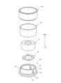
- FIG. 1 is an exploded perspective view of a motor to which a bearing retaining device according to an embodiment is applied;
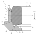
- FIG. 2 is an enlarged axial cross-sectional view of a portion X in FIG. 1 .
- FIG. 3 is an exploded perspective view of the bearing retainer and the plain bearing of FIG. 2 .
- 3 is an enlarged axial half cross-sectional view of a bearing holder, a support portion, and a plain bearing provided in the bearing retaining device of FIG. 2.
- 5 is an enlarged axial half-sectional view of a bearing holder and a plain bearing provided in a bearing retaining device of a first modified example, the view corresponding to the half-sectional view of FIG. 4 .
- FIG. 4 is an enlarged axial half-sectional view of a bearing holder and a plain bearing provided in a bearing retaining device of a first modified example, the view corresponding to the half-sectional view of FIG. 4 .
- FIG. 5 is an enlarged axial half-sectional view of a bearing holder and a plain bearing provided in a bearing retaining device of a second modified example, the view corresponding to the half-sectional view of FIG. 4 .
- FIG. 5 is an enlarged axial half-sectional view of a bearing holder and a plain bearing provided in another example of a bearing retaining device of the second modified example, the view corresponding to the half-sectional view of FIG. 4 .
- FIG. 5 is an enlarged axial half-sectional view of a bearing holder and a plain bearing provided in another example of a bearing retaining device of the second modified example, the view corresponding to the half-sectional view of FIG. 4 .
- the direction in which the center line of the shaft extends is referred to as the axial direction
- the direction perpendicular to the center line is referred to as the radial direction
- the direction going around the center line is referred to as the circumferential direction.
- the direction away from the center of the shaft i.e., the center of the axial length (longitudinal direction) of the shaft
- the opposite direction is referred to as "the other side.
- the direction toward the center line is referred to as "inward”
- the opposite direction (the direction away from the center line) is referred to as "outward.”
- FIG. 1 is an exploded perspective view of a motor 1 to which a bearing retaining device 10 (hereinafter simply referred to as the "retaining device") of this embodiment is applied, with a portion where the retaining device 10 is provided being partially cut away.
- the motor 1 is, for example, a permanent magnet field type, brushed inner rotor type DC motor, and includes a cylindrical housing 3 (fixed member) with a bottom and a flat end plate 4 (fixed member) that closes an opening 3P of the housing 3.
- the housing 3 incorporates a rotor 5 that rotates integrally with the shaft 2, and a cylindrical stator 6 that is disposed radially outward of the rotor 5 and facing the rotor 5.
- a brush holder 7 that supports brushes that come into sliding contact with a commutator of the rotor 5 is provided between the end plate 4 and the rotor 5.
- the motor 1 to which the holding device 10 is applied is not limited to a brushed inner rotor type motor.
- the motor 1 may be, for example, an outer rotor type motor in which the stator 6 is disposed radially inward from the rotor 5.
- the motor 1 may also be a brushless motor. In this case, the brush holder 7 is not required.
- the shaft 2 is a rotating shaft that supports the rotor 5, and also functions as an output shaft that extracts the output (mechanical energy) of the motor 1 to the outside.
- the bottom 3Q of the housing 3 is provided with a recess 3R (cylindrical portion) recessed in the axial direction on its inner side.
- the end plate 4 is also provided with a recess 4R (cylindrical portion) recessed in the axial direction on its inner side.
- Both ends of the shaft 2 are rotatably supported by slide bearings 9 provided in the respective recesses 3R, 4R.
- the retaining device 10 of this embodiment retains the slide bearings 9, and may be applied to both the recess 3R of the housing 3 and the recess 4R of the end plate 4.
- the retaining device 10 provided in the recess 3R of the housing 3 is exemplified, but when the retaining device 10 is applied to the recess 4R of the end plate 4, a configuration similar to that described below can be applied to the end plate 4 side.
- the recess 3R may have a cylindrical shape with a uniform inner diameter in the axial direction, or may have a tapered shape in which the inner diameter of the end portion on one side (hereinafter referred to as the "tapered portion 3Ra") decreases toward one side as shown in the figure.
- the portion corresponding to the bottom surface (end surface on one side in the axial direction) of the recess 3R may be an opening as shown in FIG. 2, or may have a bottom surface portion with an opening through which the shaft 2 passes.
- the plain bearing 9 is a so-called oil-impregnated bearing impregnated with lubricating oil.
- a so-called pumping action occurs and the lubricating oil in the pores of the plain bearing 9 is sucked out to the outside.
- the oil in contact with the surface of the plain bearing 9 is absorbed into the pores by capillary action.
- the viscosity of the lubricating oil for the sliding bearing 9 is not particularly limited. However, from the viewpoint of suppressing the generation of abnormal noise, which will be described later, it is preferable that the viscosity of the lubricating oil is low enough to constitute an oil-impregnated bearing that can obtain sufficient lubrication even in a low-temperature environment (to be able to function as an oil-impregnated bearing). It is also preferable that excessive outflow due to viscosity reduction does not occur even in a high-temperature environment.
- the viscosity of the lubricating oil at 40°C is set to be, for example, 8 mm 2 /s or more and 20 mm 2 /s or less.
- the through hole 9h only needs to have an inner diameter large enough to insert the shaft 2, and the inner diameter may or may not be uniform in the axial direction.
- the through hole 9h is preferably tapered so that the inner diameter becomes smaller toward the center in the axial direction. This ensures proper lubrication even if the shaft 2 is tilted, and also helps to suppress the generation of abnormal noise, which will be described later.
- the retaining device 10 is provided with a bearing holder 20 that is fixed to the recess 3R and holds the plain bearing 9.
- the retaining device 10 of this embodiment is further provided with a support portion 30 and an annular fixing member 40 (cylindrical portion), and preferably also with a vibration damping member 50.
- the plain bearing 9 may generate abnormal noises (e.g., a squealing sound) when the shaft 2 rotates.
- the lubricity of the plain bearing 9 decreases (e.g., the lubricating oil becomes thicker), making the above-mentioned abnormal noise more likely to occur.
- the inventor has found that providing a damping force on the outside of the plain bearing 9 is an effective means for suppressing the generation of such abnormal noises. Therefore, in the retention device 10 of this embodiment, the bearing holder 20 is provided with a configuration that exerts a high damping force on the outside of the plain bearing 9.
- a support portion 30 is provided to maintain the damping force of the bearing holder 20, and a vibration-damping member 50 may be provided between the bearing holder 20 and the annular fixing member 40 to further increase the damping force on the outside of the plain bearing 9.
- the bearing holder 20 is a member that is fixed to the recess 3R and holds the plain bearing 9.
- the bearing holder 20 is provided with an opposing surface 21c that faces one end face 9c (end face) on one side of the plain bearing 9 in the axial direction, and a retaining portion 22 that extends from the outer edge of the opposing surface 21c toward the other side in the axial direction.
- the opposing surface 21c is provided on the base portion 21 on one side of the retaining portion 22.
- the bearing holder 20 is further provided with a fixing portion 23 for fixing the bearing holder 20 to the recess 3R.
- the bearing holder 20 has a substantially circular opposing surface 21c facing the other side in the axial direction, and a retaining portion 22 that is a curved wall (plate) extending from the outer edge (outer periphery) of the opposing surface 21c to the other side and extends in the axial and circumferential directions.
- the retaining portion 22 is a portion that surrounds the plain bearing 9 from the outside in the radial direction to hold the plain bearing 9.
- the plain bearing 9 is inserted into the inside of the retaining portion 22 from the other side in the axial direction, and the retaining portion 22 restricts the plain bearing 9 from moving to the other side and presses it inward, thereby holding it in the bearing holder 20.
- the fixing portion 23 is pressed into the inside of the recess 3R and is fixed between the recess 3R and the tapered portion 3Ra of the recess 3R by the annular fixing member 40, thereby fixing the bearing holder 20 to the recess 3R.
- the above-mentioned configuration that exerts a high damping force outside the plain bearing 9 is provided in the retaining portion 22.
- the bearing holder 20 has these sections 21 to 23 integrally formed from, for example, resin or elastomer.
- the base 21 is expanded in a direction perpendicular to the axial direction, and is defined as the portion of the bearing holder 20 on one side of the axial position of the opposing surface 21c. Therefore, the opposing surface 21c is planar and extends in a direction perpendicular to the axial direction. However, the opposing surface 21c does not have to be planar as long as it faces one end surface 9c of the sliding bearing 9 in the held state.
- the base 21 has a circular outer shape with an outer diameter larger than the outer diameter of the sliding bearing 9 when viewed in the axial direction.
- the outer diameter of the base 21 may or may not be uniform in the axial direction.
- the outer peripheral surface of the base 21 may have a tapered shape in which the outer diameter decreases toward one side, as shown in the figure, corresponding to the shape of the inner peripheral surface of the tapered portion 3Ra of the recess 3R described above.
- the base 21 also has an inner hole on its inner side through which the shaft 2 can be inserted, and for this reason the base 21 has a circular ring shape when viewed in the axial direction. Therefore, the opposing surface 21c also has a circular ring shape when viewed in the axial direction.
- the size of the inner hole of the base 21 is set to be smaller than the outer diameter of at least one end face 9c, and larger than the outer diameter of the shaft 2.
- the inner diameter of the inner hole of the base 21 does not have to be uniform in the axial direction, and may have a stepped shape in which the inner diameter on the other side is larger than the inner diameter on one side, as shown in the figure.
- the retaining portion 22 is a wall-like portion extending from the outer edge of the opposing surface 21c toward the other side in the axial direction, and forms a space radially inward to accommodate (retain) the plain bearing 9.
- the retaining portion 22 can be said to be a portion that surrounds the plain bearing 9 from the radial outside in the retained state, and has a claw portion 24 and a connection portion 25, as shown in Figures 3 and 4.
- the claw portion 24 is a part that contacts the other side portion of the outer circumferential surface 9f of the plain bearing 9 (hereinafter referred to as the "other side outer circumferential surface 9fb") in the retained state, restricting the plain bearing 9 from moving to the other side and pressing (urging) the plain bearing 9 inward.
- the claw portion 24 in the retained state, is located on the other side of the axial center C of the plain bearing 9 and extends in the circumferential direction as shown in FIG. 3.
- the claw portion 24 forms an inner circumferential surface (hereinafter referred to as the "other side inner circumferential surface 24f") that faces inward and surrounds the other side outer circumferential surface 9fb.
- the other side inner circumferential surface 24f is hemispherical in shape with an inner diameter that decreases toward the other side, corresponding to the shape of the other side outer circumferential surface 9fb. Additionally, the inner diameter of the other side inner circumferential surface 24f is set to be smaller than the outer diameter of the other side outer circumferential surface 9fb when the plain bearing 9 is not held by the bearing holder 20 (hereinafter referred to as the "non-holding state").
- the holding portion 22 elastically deforms with the connection portion with the opposing surface 21c (base portion 21) as the base point, so that the claw portion 24 is displaced outward.
- the force (restoring force) that causes the holding portion 22 to return to its original state causes the claw portion 24 to abut against the other outer peripheral surface 9fb from the outside and the other side, and presses the plain bearing 9 inward and to one side, as shown by the white arrow in Figure 4.
- the above-mentioned pressing force of the claw portion 24 restricts the plain bearing 9 from moving to the other side and presses (biases) it inward.
- connection portion 25 is a portion that connects the claw portion 24 and the opposing surface 21c, and extends in the circumferential direction like the claw portion 24.
- the connection portion 25 faces inward and forms a one-side inner circumferential surface 25f that surrounds one side of the outer circumferential surface 9f of the sliding bearing 9 (hereinafter referred to as the "one-side outer circumferential surface 9fa").
- One edge of the one-side inner circumferential surface 25f is connected to the outer edge of the opposing surface 21c.
- the one-side inner circumferential surface 25f has a hemispherical shape with an inner diameter that decreases toward one side, corresponding to the shape of the one-side outer circumferential surface 9fa.
- the gap H is depicted large for ease of understanding, but it is preferable that the gap H be set narrow enough so that the plain bearing 9 does not rattle in the retaining state.
- the size of the gap H is set to, for example, several tens of ⁇ m.
- the one-side outer peripheral surface 9fa of the plain bearing 9 may include not only one side portion of the outer peripheral surface 9f but also the peripheral surface excluding the other-side outer peripheral surface 9fb (i.e., the portion near the center C).
- the claw portion 24 is illustrated as being located on the other side of the center C of the plain bearing 9 in the held state.
- the other-side outer peripheral surface 9fb of the plain bearing 9 may include not only the portion of the outer peripheral surface 9f on the other side (the other side of the center C of the plain bearing 9) but also the portion near the center C of the plain bearing 9.
- the peripheral surface of the outer peripheral surface 9f of the plain bearing 9 that is located on the other side of the one-side outer peripheral surface 9fa and that abuts the claw portion 24 is defined as the other-side outer peripheral surface 9fb
- the peripheral surface that is located on one side of the other-side outer peripheral surface 9fb and that has a gap H between it and the connection portion 25 is defined as the one-side outer peripheral surface 9fa.
- the portion that is located on the other side of the connection portion 25 and abuts the outer peripheral surface 9f (other-side outer peripheral surface 9fb) of the plain bearing 9 is defined as the claw portion 24, and the portion that is located on one side of the claw portion 24 and that has a gap H between it and the outer peripheral surface 9f (one-side outer peripheral surface 9fa) of the plain bearing 9 is defined as the connection portion 25.
- the claw portion 24 may be provided at a distance of a predetermined dimension or more from the fixing portion 23 on the other side without overlapping with the fixing portion 23 at least in the axial direction.
- the plain bearing 9 is allowed to displace radially by the gap H in the held state. Therefore, when the plain bearing 9 is displaced during rotation of the shaft 2, the displacement causes the retaining portion 22 to bend elastically, and the restoring force of the retaining portion 22 acts on the plain bearing 9 through the claw portion 24. Therefore, a damping force is generated outside the plain bearing 9, suppressing abnormal noise.
- the retaining portion 22 of this embodiment is configured to bend more easily in response to the radial displacement of the plain bearing 9 due to the above-mentioned claw portion 24 and connection portion 25.
- connection portion 25 is set to a size that can tolerate the displacement of the claw portion 24 (i.e., the above-mentioned elastic deformation of the retaining portion 22).
- the retaining portion 22 does not have to be cylindrical and surrounds the entire outer peripheral surface 9f of the sliding bearing 9 in the circumferential direction, but may be a cylinder divided in the circumferential direction, i.e., a plurality of curved wall (plate)-like portions arranged with gaps in the circumferential direction.
- the retaining portion 22 may be shaped like a roughly cylinder divided into three in the circumferential direction, as shown in FIG. 3, for example.
- the retaining portion 22 in FIG. 3 is composed of three pieces (wall-like portions) with a partial cylindrical surface (arc-shaped when viewed from the axial direction) that are spaced apart from each other in the circumferential direction (with gaps in between) and stand up from the base 21.
- each piece that constitutes the retaining portion 22 can deform independently when force is applied to each piece. This makes it easier to insert the plain bearing 9 into the bearing holder 20, and each piece can flexibly and elastically deform in response to the displacement of the plain bearing 9 in the retained state. This also improves the formability of the bearing holder 20.
- the fixing portion 23 is a generally cylindrical portion that bulges outward from the outer peripheral surface of one side of the holding portion 22 (e.g., one side of the connection portion 25).
- the outer diameter of the fixing portion 23 is set to be slightly larger than the inner diameter of the recess 3R.
- the outer diameter of the outer peripheral surface of the fixing portion 23 may or may not be uniform in the axial direction.
- the outer peripheral surface of the fixing portion 23 may have a tapered shape in which the outer diameter of the portion on one side decreases toward that side and connects to the outer peripheral surface of the base portion 21, as shown in the figure.
- the axial position of the fixing portion 23 is not limited to one side of the connection portion 25.
- the fixing portion 23 needs to be located at a position that does not impede radial displacement of the claw portion 24 (elastic deformation of the holding portion 22).
- the annular fixing member 40 is a member that fixes the bearing holder 20 by sandwiching the fixing portion 23 between the tapered portion 3Ra of the recess 3R.
- the annular fixing member 40 is, for example, a cylindrical metal ring with an outer diameter slightly larger than the inner diameter of the recess 3R and an inner diameter larger than the outer diameter of the holding portion 22.
- the annular fixing member 40 is pressed into the inside of the recess 3R on the other side of the fixing portion 23, as shown in FIG. 2.
- the bearing holder 20 is fixed by sandwiching the fixing portion 23 between the pressed-in and fixed annular fixing member 40 and the tapered portion 3Ra.
- the holding portion 22 of the bearing holder 20 is surrounded on the outside by the annular fixing member 40, and a gap is formed between the annular fixing member 40 and the holding portion 22.
- the inner diameter of the annular fixing member 40 is set to a size that allows a sufficient gap to be formed between the holding portion 22 and the holding portion 22 so as not to hinder the elastic deformation of the holding portion 22 described above.
- the vibration-damping member 50 is immediately compressed in its thickness direction, and the damping force of the vibration-damping member 50 acts on the plain bearing 9 in addition to the damping force of the holding portion 22. Therefore, the damping force on the outside of the plain bearing 9 is increased.
- the outer diameter of the vibration-damping member 50 is preferably set to be equal to or slightly larger than the inner diameter of the annular fixing member 40. This allows the vibration-damping member 50 to be compressed more reliably in response to the elastic deformation of the holding portion 22, thereby increasing the damping force on the outside of the sliding bearing 9.
- the outer diameter of the vibration-damping member 50 may be set smaller than the inner diameter of the annular fixing member 40. In this case, a gap is formed outside the vibration-damping member 50, i.e., between the vibration-damping member 50 and the annular fixing member 40, but a damping force is generated by the ring-shaped (cylindrical) rubber sheet being stretched outward in response to the elastic deformation of the holding portion 22.
- the outer diameter of the vibration-damping member 50 should be at least a diameter that allows the vibration-damping member 50 to be inserted into the gap between the holding portion 22 and the annular fixing member 40.
- an opposing surface 21c opposing one end surface 9c of the plain bearing 9 and a holding portion 22 extending from the outer edge of the opposing surface 21c toward the other side in the axial direction are provided.
- the holding portion 22 has a claw portion 24 and a connecting portion 25 connecting the opposing surface 21c and the claw portion 24.
- the claw portion 24 restricts the movement of the plain bearing 9 toward the other side, and holds the plain bearing 9 by abutting against the other side outer peripheral surface 9fb of the plain bearing 9 and pressing the plain bearing 9 radially inward.
- a gap H is provided between the connecting portion 25 and the one side outer peripheral surface 9fa of the plain bearing 9.
- the bearing holder 20 having the retaining portion 22 is made of resin or elastomer. In this way, by forming the retaining portion 22 from a material with a damping performance that has a larger loss than metal and is easier to attenuate vibrations, the damping force acting outwardly of the plain bearing 9 can be increased.
- the claw portion 24 presses against the plain bearing 9 having a spherical outer peripheral surface 9f from the outside and the other side as shown by the white arrow in FIG. 4, as in the above-mentioned retaining device 10, the plain bearing 9 is pressed to one side, and the inner peripheral surface 25f on one side of the connection portion 25 and the outer peripheral surface 9fa on one side of the plain bearing 9 may come into contact.
- the movement of the plain bearing 9 to one side is restricted by the support portion 30, so that the gap H between the connection portion 25 and the outer peripheral surface 9fa on one side is more easily maintained. This makes it possible to maintain the damping force on the outside of the plain bearing 9, and ultimately to suppress the generation of abnormal noise around the plain bearing 9.
- the support portion 30 is made of an elastic material that is elastically deformable in the axial direction. This allows the gap H between the connection portion 25 and the outer peripheral surface 9fa of one side to be appropriately maintained while allowing slight axial displacement of the plain bearing 9. This allows normal lubrication of the plain bearing 9 and suppresses the generation of abnormal noise around the plain bearing 9.
- the support portion 30 is made of an elastic material, so that it is possible to maintain the gap H between the connection portion 25 and the outer peripheral surface 9fa on one side while allowing slight displacement of the end surface 9c on one side of the plain bearing 9. Furthermore, if the plain bearing 9 tilts, the elastically deformable support portion 30 (wave washer) acts to return the plain bearing 9 to its original position. This helps the self-aligning function of the plain bearing 9. This makes it possible to suppress the generation of abnormal noise around the plain bearing 9, ensure normal lubrication of the plain bearing 9, and help the self-aligning function of the plain bearing 9.
- an oil-impregnated bearing is used as the plain bearing 9.
- the rotation of the shaft 2 lubricates the rotation of the shaft 2 by sucking the lubricating oil outward as the shaft 2 rotates.
- the lubricating oil hardens, making it difficult for the lubricating oil to be sucked outward even when the shaft 2 rotates, making it easier for abnormal noise to occur.
- the shear force of the lubricant contained in the plain bearing 9 is determined according to the viscosity (hardness) of the lubricant, the area to which the shear force is applied, the rotation speed of the shaft 2, and the size of the clearance (gap) between the plain bearing 9 and the shaft 2.
- the inventors have found that the smaller the shear force of the lubricant, the more the abnormal noise generated around the plain bearing 9 is suppressed. If the through hole 9h of the plain bearing 9 is tapered so that the inner diameter becomes smaller toward the center C in the axial direction, the area of the portion where the clearance between the plain bearing 9 and the shaft 2 becomes smaller can be made smaller.
- the area of the portion that forms a clearance larger than the clearance near the center C in the axial direction can be made larger within the through hole 9h. This makes it possible to reduce the shear force of the lubricant except for the portion near the center C in the axial direction, thereby making it possible to further suppress the generation of abnormal noise around the plain bearing 9.
- an annular fixing member 40 (cylindrical portion) is provided outside the retaining portion 22 to surround the retaining portion 22.
- a vibration-damping member 50 having a higher damping force than the retaining portion 22 is interposed between the retaining portion 22 and the annular fixing member 40.
- the configuration of the holding device 10 described above is an example, and is not limited to the above configuration.
- the support portion 30 is provided as a separate member from the bearing holder 20, but the support portion may be configured integrally with the bearing holder.
- a holding device 10' of a first modified example will be described with reference to Fig. 5.
- the holding device 10' of the first modified example differs from the holding device 10 of the embodiment (above) mainly in that the support portion 30' is provided integrally with the bearing holder 20'.
- FIG. 5 is an enlarged axial half-sectional view of the bearing holder 20' and the plain bearing 9 of the retaining device 10' of the first modified example.
- the same components as those explained in the embodiment are given the same reference numerals, and explanations of the components and effects are omitted.
- components corresponding to those explained in the embodiment are given a prime (') after the reference numerals of the embodiment, and detailed explanations are omitted.
- the bearing holder 20' of the retaining device 10' of the first modified example is provided with a support part 30' in addition to the base part 21 having the above-mentioned opposing surface 21c, the retaining part 22, and the fixed part 23.
- the support part 30' is formed in the shape of a leaf spring extending inward and toward the other side from the outer part of the opposing surface 21c of the base part 21.
- the axial position of the inner end part of the support part 30' is set in the non-retained state to be the other side of the axial position of the one side end face 9c of the plain bearing 9 in the retained state.
- the inner end part of the support part 30' is pressed to one side by the plain bearing 9, and the support part 30' is elastically deformed.
- the plain bearing 9 is restricted from moving to one side by the restoring force of the support part 30' and is urged to the other side.
- the holding device 10' of the first modified example also provides the same effects as the holding device 10 described above.
- the support portion 30' is provided integrally with the bearing holder 20', which reduces the number of parts.
- a self-aligning bearing having a spherical outer peripheral surface 9f has been exemplified as the plain bearing 9 held by the retaining device 10, but the plain bearing may also be one having a cylindrical outer peripheral surface without a self-aligning function.
- a retaining device 10'' of a second modified example will be described with reference to Figure 6.
- the retaining device 10'' of the second modified example differs from the retaining device 10 of the embodiment mainly in that it holds a plain bearing 9'' having a cylindrical outer peripheral surface 9f'' and in that a support portion 30 is not provided.
- FIG. 6 is an enlarged axial half-sectional view of a bearing holder 20" and a plain bearing 9" provided in a retaining device 10" of a second modified example.
- the same components as those explained in the embodiment are given the same reference numerals, and explanations of the components and effects are omitted.
- double quotation marks (") are added to the reference numerals of the embodiment for components corresponding to those explained in the embodiment, and detailed explanations are omitted.
- the plain bearing 9" held by the retaining device 10" of the second modified example is a bearing having a cylindrical outer peripheral surface 9f" as described above.
- the outer diameter of the outer peripheral surface 9f" is, for example, uniform in the axial direction.
- the plain bearing 9" is provided with one end face 9c and an other end face 9d that faces the other of the end faces of the plain bearing 9".
- the plain bearing 9" also has a one-side tapered surface 9ga that connects the one-side end face 9c and the outer peripheral surface 9f", and an other-side tapered surface 9gb that connects the other end face 9d and the outer peripheral surface 9f".
- the through hole 9h" of the plain bearing 9" may be tapered, with the inner diameter decreasing toward the axial center C, similar to the through hole 9h described above. In this case, the generation of abnormal noise can be further suppressed, and even if the plain bearing 9" itself does not have a self-aligning function, the shape of the through hole 9h" can tolerate slight tilt of the shaft 2, so that normal lubrication performance can be obtained even if the shaft 2 is tilted.
- the bearing holder 20" of the retaining device 10" has a retaining portion 22" for retaining such a plain bearing 9".
- the retaining portion 22" is an extension from the opposing surface 21c to the other side, similar to the retaining portion 22 described above, and has a claw portion 24" and a connection portion 25". Note that in this modified example, the support portion 30 provided in the retaining device 10 of the embodiment is omitted, and one side end surface 9c of the plain bearing 9" abuts against the opposing surface 21c in the retained state.
- the claw portion 24" is a portion that, in the retained state, comes into contact with the other side outer peripheral surface 9fb" of the plain bearing 9" and presses (biases) the plain bearing 9" inward.
- the claw portion 24" faces inward and forms an other side inner peripheral surface 24f" that surrounds the other side outer peripheral surface 9fb".
- the other side inner peripheral surface 24f" has an inner diameter that is slightly smaller than the outer diameter of the other side outer peripheral surface 9fb" in the non-retained state.
- the claw portion 24" is also provided with a restricting portion 24g that forms a surface that faces inward on one side of the other side of the other side inner peripheral surface 24f". In the retained state, the claw portion 24" restricts the movement of the plain bearing 9" to the other side by the above-mentioned surface of the restricting portion 24g coming into contact with the other side tapered surface 9gb of the plain bearing 9".
- the claw portion 24" extends from the vicinity of the center C of the plain bearing 9" to the other side.
- the other side inner peripheral surface 24f" abuts the other side portion including the vicinity of the center C of the outer peripheral surface 9f
- the other side outer peripheral surface 9fb" of the plain bearing 9" includes not only the other side portion of the outer peripheral surface 9f" (the other side of the center C of the plain bearing 9") but also the portion near the center C of the plain bearing 9".
- the claw portion 24" need only be spaced a predetermined distance or more away from the fixed portion 23 at least in the axial direction without overlapping with the fixed portion 23, and may extend from one side of the vicinity of the center C of the plain bearing 9" to the other side including the vicinity of the center C, or may extend from the other side of the center C of the plain bearing 9" to the other side.
- connection portion 25" is a portion that connects the claw portion 24" and the opposing surface 21c, like the connection portion 25 described above, and faces inward to form a one-side inner peripheral surface 25f" that surrounds the one-side outer peripheral surface 9fa" of the plain bearing 9".
- the inner diameter of the one-side inner peripheral surface 25f" is set to be larger than the outer diameter of the one-side outer peripheral surface 9fa" in order to form a gap H between the one-side outer peripheral surface 9fa" in the retained state.
- the one-side inner peripheral surface 25f" may have a uniform inner diameter in the axial direction, or may be slightly enlarged toward one side as shown in the figure.
- connection portion 25" may be provided so as to form a gap between the one-side tapered surface 9ga of the plain bearing 9".
- the connection portion 25" may be provided so as to form a gap H at least in the region that overlaps with the fixed portion 23 in the axial direction.
- the second modified retaining device 10" shown in FIG. 6 also provides the same effect as the retaining device 10 described above.
- radial displacement of the plain bearing 9" is permitted by the amount of the gap H. This causes a loss in the retaining portion 22" that corresponds to the amount of displacement, thereby increasing the damping force of the retaining portion 22" and suppressing the generation of abnormal noise around the plain bearing 9".
- FIG. 7 is an enlarged axial half cross-sectional view of the bearing holder 20" and the plain bearing 9" provided in the retaining device 10" of another example of the second modified example.
- the outer peripheral surface 9fa" of one side of the plain bearing 9" is slightly reduced in diameter toward one side, so that a gap H is formed between the connecting portion 25" and the outer peripheral surface 9fa".
- the member that is released (the shape of which is devised) to ensure the gap H may be the plain bearing 9" instead of the bearing holder 20".
- the inner diameter of the inner peripheral surface 25f" of one side of the connecting portion 25" may be uniform in the axial direction.
- the retaining device 10" of the other example shown in FIG. 7 also has the same effect as that of FIG. 6.
- the bearing holders 20, 20', 20" need only be made of a material that has at least damping properties, and do not have to be made of resin or elastomer. Also, the bearing holders 20, 20', 20" need only have at least the retaining parts 22, 22" made of a material that has damping properties, and the base 21, fixing part 23, and support part 30' may be made of a material different from the retaining parts 22, 22".
- the opposing surface 21c need only be a surface that faces at least one end surface 9c of the sliding bearing 9, 9'', and need not be flat or annular.
- the shape of the base 21 on which the opposing surface 21c is provided is not limited to the shape described above.
- the bearing holder 20, 20', 20" may be provided with a portion that engages with the recesses 3R, 4R instead of the fixing portion 23.
- the bearing holder 20, 20', 20" does not need to be fixed to the housing 3 or end plate 4, and may be formed integrally with the housing 3 or end plate 4.
- a wave washer is exemplified as the support part 30 that is provided separately from the bearing holders 20, 20" and is made of an elastic material that can elastically deform in the axial direction, but the support part 30 does not have to be a wave washer.
- the support part 30 may be, for example, a spring material that can expand and contract in the axial direction, or a rubber ring. When the support part 30 is made of a rubber ring, a higher damping force can be obtained than with a metal wave washer.
- the support portion 30, 30' does not have to be an elastic member that can be elastically deformed in the axial direction.
- the support portion 30, 30' may be, for example, a protrusion protruding from the opposing surface 21c of the base 21.
- the support portion 30, 30' may be omitted if the holding device 10, 10' does not require the self-aligning function of the plain bearing 9.
- one side end surface 9c of the plain bearing 9 may abut against the opposing surface 21c of the base 21 in the held state, similar to the holding device 10'' of the second modified example.
- the above-mentioned support portion 30, 30' may be provided in the holding device 10'' of the second modified example.
- the method of fixing the annular fixing member 40 to the recesses 3R, 4R is not limited to press-fitting.
- the annular fixing member 40 only needs to be fixed to the recesses 3R, 4R so as to at least perform the function of fixing the bearing holders 20, 20', 20", and may be fixed by crimping or welding, for example.
- the bearing holders 20, 20', 20" are formed integrally with the housing 3 or the end plate 4, for example by integral molding or processing with a 3D printer, and have a structure that cannot move relative to the housing 3 or the end plate 4, the annular fixing member 40 may be omitted.
- the vibration-damping member 50 may be interposed between the retaining portion 22, 22" and the recesses 3R, 4R.
- the "cylindrical portion surrounding the retaining portion from the outside” described in the claims is not limited to the annular fixing member 40, but may be the recess 3R of the housing 3 or the recess 4R of the end plate 4.
- the above-mentioned “cylindrical portion” may be formed integrally with the bearing holder 20, 20', 20".
- the vibration-damping member 50 has been described as having an inner diameter slightly smaller than the outer diameter of the holding portion 22, 22'', but the inner diameter of the vibration-damping member 50 is not limited to this.
- the vibration-damping member 50 may have an inner diameter slightly larger than the outer diameter of the holding portion 22, 22'', forming a small gap between the vibration-damping member 50 and the holding portion 22, 22''.
- the elastic deformation of the holding portion 22, 22'' is less likely to be hindered by the vibration-damping member 50, and when the holding portion 22, 22'' is significantly deformed, the holding portion 22, 22'' comes into contact with the vibration-damping member 50, and the damping force of the vibration-damping member 50 acts on the sliding bearing 9, 9'' in addition to the damping force of the holding portion 22, 22''. Therefore, the damping force on the outside of the sliding bearing 9, 9'' is increased.
- the vibration-damping member 50 interposed between the retaining portion 22, 22" and the annular fixing member 40 may be omitted.
- the retaining device 10, 10', 10" may be provided with a vibration-damping member having a higher damping force than the retaining portion 22, 22" between the claw portion 24, 24" and the plain bearing 9, 9".
- the vibration-damping member is a separate part from the vibration-damping member 50 described above, and may be made of the same material or a different material. With this configuration, a higher damping force can be provided on the outside of the plain bearing 9, 9".
- the holding devices 10, 10', 10" need only hold the plain bearings 9, 9" that support the rotating shaft 2, and the device to which the holding devices 10, 10', 10" are applied is not limited to a motor.
- the device (rotating machine) to which the holding devices 10, 10', 10" are applied may be, for example, an engine.
Landscapes
- Engineering & Computer Science (AREA)
- General Engineering & Computer Science (AREA)
- Mechanical Engineering (AREA)
- Chemical & Material Sciences (AREA)
- Oil, Petroleum & Natural Gas (AREA)
- Support Of The Bearing (AREA)
Priority Applications (4)
| Application Number | Priority Date | Filing Date | Title |
|---|---|---|---|
| DE112023004749.9T DE112023004749T5 (de) | 2023-10-26 | 2023-10-26 | Lagerhaltevorrichtung und Elektromotor |
| JP2025518441A JPWO2025088760A1 (https=) | 2023-10-26 | 2023-10-26 | |
| CN202380092747.1A CN120530270A (zh) | 2023-10-26 | 2023-10-26 | 轴承保持装置以及马达 |
| PCT/JP2023/038742 WO2025088760A1 (ja) | 2023-10-26 | 2023-10-26 | 軸受保持装置及びモータ |
Applications Claiming Priority (1)
| Application Number | Priority Date | Filing Date | Title |
|---|---|---|---|
| PCT/JP2023/038742 WO2025088760A1 (ja) | 2023-10-26 | 2023-10-26 | 軸受保持装置及びモータ |
Publications (1)
| Publication Number | Publication Date |
|---|---|
| WO2025088760A1 true WO2025088760A1 (ja) | 2025-05-01 |
Family
ID=95515424
Family Applications (1)
| Application Number | Title | Priority Date | Filing Date |
|---|---|---|---|
| PCT/JP2023/038742 Pending WO2025088760A1 (ja) | 2023-10-26 | 2023-10-26 | 軸受保持装置及びモータ |
Country Status (4)
| Country | Link |
|---|---|
| JP (1) | JPWO2025088760A1 (https=) |
| CN (1) | CN120530270A (https=) |
| DE (1) | DE112023004749T5 (https=) |
| WO (1) | WO2025088760A1 (https=) |
Citations (9)
| Publication number | Priority date | Publication date | Assignee | Title |
|---|---|---|---|---|
| JPS506937A (https=) * | 1973-05-24 | 1975-01-24 | ||
| JPS5387342U (https=) * | 1976-12-18 | 1978-07-18 | ||
| JPS5479351U (https=) * | 1977-11-16 | 1979-06-05 | ||
| JPS57114024A (en) * | 1980-11-17 | 1982-07-15 | Gulf & Western Mfg Co | Bearing |
| JPS6150824U (https=) * | 1984-09-07 | 1986-04-05 | ||
| JPH10339323A (ja) * | 1997-06-06 | 1998-12-22 | Asmo Co Ltd | すべり軸受け及びモータ |
| JPH11191944A (ja) * | 1997-12-25 | 1999-07-13 | Ntn Corp | レーザビームプリンタのスピンドルモータ及び回転軸支持装置 |
| JP2001152174A (ja) * | 1999-11-24 | 2001-06-05 | Hitachi Powdered Metals Co Ltd | 焼結含油軸受 |
| JP2006105394A (ja) * | 2004-10-06 | 2006-04-20 | Minebea Co Ltd | 軸受アセンブリ |
-
2023
- 2023-10-26 JP JP2025518441A patent/JPWO2025088760A1/ja active Pending
- 2023-10-26 DE DE112023004749.9T patent/DE112023004749T5/de active Pending
- 2023-10-26 CN CN202380092747.1A patent/CN120530270A/zh active Pending
- 2023-10-26 WO PCT/JP2023/038742 patent/WO2025088760A1/ja active Pending
Patent Citations (9)
| Publication number | Priority date | Publication date | Assignee | Title |
|---|---|---|---|---|
| JPS506937A (https=) * | 1973-05-24 | 1975-01-24 | ||
| JPS5387342U (https=) * | 1976-12-18 | 1978-07-18 | ||
| JPS5479351U (https=) * | 1977-11-16 | 1979-06-05 | ||
| JPS57114024A (en) * | 1980-11-17 | 1982-07-15 | Gulf & Western Mfg Co | Bearing |
| JPS6150824U (https=) * | 1984-09-07 | 1986-04-05 | ||
| JPH10339323A (ja) * | 1997-06-06 | 1998-12-22 | Asmo Co Ltd | すべり軸受け及びモータ |
| JPH11191944A (ja) * | 1997-12-25 | 1999-07-13 | Ntn Corp | レーザビームプリンタのスピンドルモータ及び回転軸支持装置 |
| JP2001152174A (ja) * | 1999-11-24 | 2001-06-05 | Hitachi Powdered Metals Co Ltd | 焼結含油軸受 |
| JP2006105394A (ja) * | 2004-10-06 | 2006-04-20 | Minebea Co Ltd | 軸受アセンブリ |
Also Published As
| Publication number | Publication date |
|---|---|
| JPWO2025088760A1 (https=) | 2025-05-01 |
| CN120530270A (zh) | 2025-08-22 |
| DE112023004749T5 (de) | 2025-09-11 |
Similar Documents
| Publication | Publication Date | Title |
|---|---|---|
| JP2004003582A (ja) | 動圧軸受装置 | |
| JP2005299922A (ja) | フォイル式動圧ジャーナル軸受及びその製造方法。 | |
| JP4442610B2 (ja) | 軸受構造 | |
| WO2025088760A1 (ja) | 軸受保持装置及びモータ | |
| WO2020059695A1 (ja) | 軸受装置 | |
| JP2008283750A (ja) | 油圧ダンパ用モータ | |
| JP2004190855A (ja) | スピンドルモータ | |
| JP2002206525A (ja) | ニードル軸受 | |
| CN2809319Y (zh) | 旋转受限的调心轴承组件 | |
| WO2021166136A1 (ja) | コンプレッサ | |
| JP7479261B2 (ja) | モータ | |
| JPH02179239A (ja) | 玉軸受支持装置 | |
| JP2000055055A (ja) | 転がり軸受用保持器 | |
| JP7804541B2 (ja) | ボールベアリングの保持構造及びファンモータ並びにボールベアリングの保持構造の製造方法 | |
| US12560236B2 (en) | Bearing spacer | |
| JP7811306B1 (ja) | 保持部材、モータ及びブロア | |
| JP3892995B2 (ja) | 動圧型軸受ユニット | |
| JP3386965B2 (ja) | スピンドルモータの軸受構造 | |
| JP2000087964A (ja) | モータ支持軸受構造 | |
| JPH02223346A (ja) | モータ | |
| JP2002235736A (ja) | スピンドルモータ | |
| JP2532997B2 (ja) | 滑り軸受用合成樹脂ブッシュ | |
| JPWO2025088760A5 (https=) | ||
| JP3586044B2 (ja) | モータ用軸受装置 | |
| JP2003184891A (ja) | ジャーナル用ベアリング構体 |
Legal Events
| Date | Code | Title | Description |
|---|---|---|---|
| ENP | Entry into the national phase |
Ref document number: 2025518441 Country of ref document: JP Kind code of ref document: A |
|
| WWE | Wipo information: entry into national phase |
Ref document number: 2025518441 Country of ref document: JP |
|
| 121 | Ep: the epo has been informed by wipo that ep was designated in this application |
Ref document number: 23956811 Country of ref document: EP Kind code of ref document: A1 |
|
| WWE | Wipo information: entry into national phase |
Ref document number: 112023004749 Country of ref document: DE |
|
| WWE | Wipo information: entry into national phase |
Ref document number: 202380092747.1 Country of ref document: CN |
|
| WWP | Wipo information: published in national office |
Ref document number: 202380092747.1 Country of ref document: CN |
|
| WWP | Wipo information: published in national office |
Ref document number: 112023004749 Country of ref document: DE |