WO2025084269A1 - ボールねじ及びボールねじ用シール部品 - Google Patents
ボールねじ及びボールねじ用シール部品 Download PDFInfo
- Publication number
- WO2025084269A1 WO2025084269A1 PCT/JP2024/036617 JP2024036617W WO2025084269A1 WO 2025084269 A1 WO2025084269 A1 WO 2025084269A1 JP 2024036617 W JP2024036617 W JP 2024036617W WO 2025084269 A1 WO2025084269 A1 WO 2025084269A1
- Authority
- WO
- WIPO (PCT)
- Prior art keywords
- plate
- ball screw
- nut
- sealing
- seal
- Prior art date
- Legal status (The legal status is an assumption and is not a legal conclusion. Google has not performed a legal analysis and makes no representation as to the accuracy of the status listed.)
- Pending
Links
Images


Classifications
-
- F—MECHANICAL ENGINEERING; LIGHTING; HEATING; WEAPONS; BLASTING
- F16—ENGINEERING ELEMENTS AND UNITS; GENERAL MEASURES FOR PRODUCING AND MAINTAINING EFFECTIVE FUNCTIONING OF MACHINES OR INSTALLATIONS; THERMAL INSULATION IN GENERAL
- F16H—GEARING
- F16H25/00—Gearings comprising primarily only cams, cam-followers and screw-and-nut mechanisms
- F16H25/18—Gearings comprising primarily only cams, cam-followers and screw-and-nut mechanisms for conveying or interconverting oscillating or reciprocating motions
- F16H25/20—Screw mechanisms
- F16H25/22—Screw mechanisms with balls, rollers, or similar members between the co-operating parts; Elements essential to the use of such members
-
- F—MECHANICAL ENGINEERING; LIGHTING; HEATING; WEAPONS; BLASTING
- F16—ENGINEERING ELEMENTS AND UNITS; GENERAL MEASURES FOR PRODUCING AND MAINTAINING EFFECTIVE FUNCTIONING OF MACHINES OR INSTALLATIONS; THERMAL INSULATION IN GENERAL
- F16H—GEARING
- F16H25/00—Gearings comprising primarily only cams, cam-followers and screw-and-nut mechanisms
- F16H25/18—Gearings comprising primarily only cams, cam-followers and screw-and-nut mechanisms for conveying or interconverting oscillating or reciprocating motions
- F16H25/20—Screw mechanisms
- F16H25/24—Elements essential to such mechanisms, e.g. screws, nuts
-
- F—MECHANICAL ENGINEERING; LIGHTING; HEATING; WEAPONS; BLASTING
- F16—ENGINEERING ELEMENTS AND UNITS; GENERAL MEASURES FOR PRODUCING AND MAINTAINING EFFECTIVE FUNCTIONING OF MACHINES OR INSTALLATIONS; THERMAL INSULATION IN GENERAL
- F16J—PISTONS; CYLINDERS; SEALINGS
- F16J15/00—Sealings
- F16J15/02—Sealings between relatively-stationary surfaces
- F16J15/06—Sealings between relatively-stationary surfaces with solid packing compressed between sealing surfaces
Definitions
- the present invention relates to a ball screw and a sealing part used in the ball screw.
- ball screws that convert rotational motion into linear motion generally comprise a screw shaft with a helical thread groove formed on its outer circumferential surface and a nut with a helical thread groove formed on its inner circumferential surface, and between the thread grooves of the screw shaft and the nut are loaded a large number of balls that roll in conjunction with the rotational motion of the screw shaft or the nut.
- a seal member is usually attached to the end of the nut of the ball screw.
- the seal member has two functions: to prevent grease from leaking from inside the nut, and to prevent foreign matter from entering the nut.
- Patent Document 1 discloses a sealing member that includes a plurality of base plates, a spacer plate sandwiched between the two base plates, and a seal plate that is placed in the seal receiving hole of the spacer plate.
- Patent Document 2 proposes a sealing member that is held by a cover member by combining two identically shaped seal plates having holes that correspond to the cross-sectional shape of the screw groove of the screw shaft at right angles to the axis. These sealing members are thin plates with the aim of designing the nut compactly in the longitudinal direction.
- the sealing members described in Patent Documents 1 and 2 are made of synthetic resin film, rubber or synthetic resin-impregnated fiber sheet, or felt-like material made of a fiber body in which resin fiber and rubber elastic body are fused together.
- sealing members made from synthetic resin films and sealing members made from fiber sheets impregnated with rubber or synthetic resin generally lack flexibility and have poor adhesion to the ball screw shaft, making it difficult to obtain good sealing properties by pressing the sealing member against the surface of the screw shaft, and there is a risk that grease leakage and intrusion of foreign matter cannot be sufficiently suppressed.
- felt-like materials are made by compressing hair-like fibers, so they have no flexibility or elasticity and are difficult to return to their original shape when deformed, so there is a risk that the desired sealing properties cannot be obtained.
- the present invention was made in consideration of the above-mentioned problems, and aims to provide a ball screw and a sealing member for a ball screw that can improve adhesion with the outer peripheral surface of the ball screw shaft, have excellent sealing properties, and reduce wear on the sealing plate.
- a ball screw comprising: a threaded shaft having a helical thread groove formed on its outer circumferential surface; a nut having a helical thread groove formed on its inner circumferential surface; a plurality of balls rolling on a load track defined by the thread groove of the threaded shaft and the thread groove of the nut; and a seal member attached to at least one axial end of the nut and sealing a gap between the threaded shaft and the nut, a sealing member that has a ring-shaped sealing plate having an inner surface that contacts the outer surface of the screw shaft, and a pair of ring-shaped retaining plates that sandwich the sealing plate, and the sealing plate is made of a sponge material.
- the ball screw and ball screw seal member of the present invention have a seal plate made of a specific flexible material, which improves adhesion to the outer circumferential surface of the screw shaft, suppresses leakage of lubricant from inside the nut, and prevents the intrusion of foreign matter from the outside.
- the material that constitutes the seal plate absorbs the lubricant, friction between the seal plate and the screw shaft can be reduced, and wear on the seal plate can be suppressed.
- FIG. 1 is a side view showing a ball screw according to a first embodiment of the present invention.
- FIG. 2 is an enlarged partial cross-sectional view showing a part of the ball screw according to the first embodiment shown in FIG.
- FIG. 3 is a front view showing a face plate for pressing the seal member and the seal member in the first embodiment.
- FIG. 4A is a front view showing the shape of a holding plate in the first embodiment.
- FIG. 4B is a front view showing the shape of the sealing plate in the first embodiment.
- FIG. 4C is a front view showing the shape of the holding plate in the first embodiment.
- FIG. 5 is an enlarged partial cross-sectional view showing a part of a ball screw according to a second embodiment of the present invention.
- FIG. 6A is a front view showing a seal member according to the second embodiment.
- FIG. 6B is a diagram showing a part of a cross section taken along line AA in FIG. 6A.
- FIG. 7A is a front view showing the shape of a holding plate in the second embodiment.
- FIG. 7B is a front view showing the shape of the sealing plate in the second embodiment.
- FIG. 7C is a front view showing the shape of a holding plate in the second embodiment.
- FIG. 8 is a schematic diagram showing an example of an ultrasonic welding device for integrating the sealing members.
- FIG. 9 is a perspective view showing a method of assembling the ball screw according to the second embodiment.
- Fig. 1 is a side view showing the ball screw according to the first embodiment of the present invention.
- Fig. 2 is a partial cross-sectional view showing an enlarged view of a part of the ball screw according to the first embodiment shown in Fig. 1.
- the ball screw 10 comprises a screw shaft 20 extending in the axial direction and having a helical screw groove 21 on its outer circumferential surface, a nut 30 having a helical screw groove 31 on its inner circumferential surface corresponding to the screw groove 21 of the screw shaft 20, a plurality of balls 50 rolling on a load track formed by the screw groove 21 of the screw shaft 20 and the screw groove 31 of the nut 30, and a seal member 40 that seals the gap between the screw shaft 20 and the nut 30.
- the outer peripheral surface of the nut 30 is provided with a number of return paths (not shown), each of which has a scooping portion that scoops up the balls and penetrates the nut 30 so that both ends advance into the load track.
- the balls scooped up at one end of the load track pass through the return path and are returned to the other end of the load track, forming an infinite circulation path.
- the nut 30 has a flange portion 32 formed on one axial end side, and a circular recess 33 having an inner diameter larger than the largest outer peripheral surface of the screw shaft 20 is formed concentrically with the screw shaft 20 at both axial ends.
- the flange portion 32 is fixed to a moving stand or the like of a mechanical device (not shown) with a mounting bolt or the like.
- the sealing member 40 has a ring-shaped sealing plate 42 made of sponge material and a pair of ring-shaped holding plates 41, 43 that sandwich the sealing plate, which are stacked and placed on the inner circumferential surface of the circular recess 33.
- the axial length of the circular recess 33 is designed to be shorter than the thickness of the holding plate 41, sealing plate 42, and holding plate 43 when stacked, forming a pressing margin for the sealing member 40.
- Figure 3 is a front view showing the face plate 60 for holding the seal member 40 and the seal member 40 in the first embodiment.
- the face plate 60 is disposed on the axial end side of the seal member 40, and the face plate 60 is fastened to the nut 30 by a fixing member 61 such as a bolt or a retaining ring.
- the seal member 40 is fixed to both axial ends of the nut 30 with the seal plate 42 being deformed in the thickness direction by being pressed against the face plate 60.
- the material constituting the face plate 60 can be appropriately selected from the same steel material as the nut 30, or a non-porous rubber that is harder than the seal plate 42, etc.
- the face plate 60 is made of rubber, not only the seal member 40 but also the face plate 60 may deform when the face plate 60 is fixed to the nut 30.
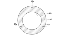
- FIG. 4A is a front view showing the shape of the retaining plate 41 in the first embodiment
- FIG. 4B is a front view showing the shape of the sealing plate 42
- FIG. 4C is a front view showing the shape of the retaining plate 43.
- the seal plate 42 is made of sponge material and has a seal plate hole 42b in the center.
- the seal plate hole 42b has a shape similar to the cross-sectional shape perpendicular to the axial direction of the screw shaft 20. However, since the cross-sectional shape of the screw shaft 20 varies depending on the axial position, the seal plate hole 42b corresponds to the shape of the screw shaft 20 at the phase where the seal plate 42 is arranged.
- the size of the seal plate hole 42b is also formed smaller than the cross-sectional shape of the screw shaft 20 by the amount of the "tightening margin". Therefore, when the screw shaft 20 is passed through the seal plate hole 42b, the inner surface of the seal plate 42, i.e., the tightening margin portion, comes into contact with the outer surface of the screw shaft 20.
- the retaining plates 41 and 43 also have retaining plate holes 41b and 43b in the center.
- the retaining plate holes 41b and 43b also have shapes similar to the cross-sectional shape perpendicular to the axial direction of the screw shaft 20.
- the cross-sectional shape of the screw shaft 20 varies depending on the axial position, so the shapes of the retaining plate holes 41b and 43b are different and correspond to the shape of the screw shaft 20 at the phase in which the retaining plates 41 and 43 are arranged.
- the size of the retaining plate holes 41b and 43b is formed slightly larger than the cross-sectional shape of the screw shaft 20 at each position, so that the inner circumferential surfaces of the retaining plates 41 and 43 do not come into contact with the outer circumferential surface of the screw shaft 20.
- the retaining plate 41, the sealing plate 42, and the retaining plate 43 each have three screw holes 41a, 42a, and 43a so that they are in the same position when they are stacked. Then, the fixing member 61 is inserted from the face plate 60 side and fastened to the nut 30, so that the retaining plate 41, the sealing plate 42, and the retaining plate 43 are fixed in their respective positions that correspond to the phase of the screw shaft 20.
- the sealing member 40 is fixed by the face plate 60, the inner peripheral surface of the sealing plate 42 protrudes toward the screw shaft 20, and the retaining plates 41 and 43 do not come into contact with the outer peripheral surface of the screw shaft 20, and only the sealing plate 42 comes into contact with the screw shaft 20.
- the screw groove 31 of the nut 30 and the screw groove 21 of the screw shaft 20 always face each other, so once the relative positional relationship between the nut 30 and the seal member 40 is determined, the cross-sectional shape of the screw shaft 20 at that position is automatically determined.
- the shapes of the retaining plate holes 41b, 43b and the seal plate hole 42b correspond to the cross-sectional shape of the screw shaft at the center of the plate thickness direction of each component.
- the inner surface shapes of the retaining plate 41, the seal plate 42 and the retaining plate 43 may be determined taking into account the amount of axial movement due to deformation and the change in thickness during deformation.
- the multiple balls 50 roll in a circulation path consisting of a load track and a return path, moving the nut 30 in the axial direction of the screw shaft 20. At this time, the gap between the screw shaft 20 and the nut 30 can be sealed by the seal member 40 attached to the axial end of the nut 30.
- the seal plate 42 constituting the seal member 40 is made of a sponge material with excellent flexibility.
- the sponge material is a porous body having air bubbles inside, but if it is only a sponge material, depending on its hardness, it may not be possible to sufficiently prevent foreign matter from entering the nut and prevent the lubricant in the nut from leaking out of the nut.
- the seal plate 42 is sandwiched between a pair of holding plates 41, 43 made of a material harder than the seal plate 42, and the holding plate holes 41b, 43b have a shape that follows the outer circumferential surface of the screw shaft 20, so that the shape of the seal plate hole 42b of the seal plate 42 can be maintained.
- the sponge material is more flexible than the felt material and also has a moderate elasticity, so that even when pressed against the outer circumferential surface of the screw shaft 20, the force that tries to return to the original shape is strong. Therefore, the tightening margin of the seal plate 42 can be reliably brought into close contact with the outer circumferential surface of the screw shaft 20, and the sealing performance can be further improved compared to conventional ball screws.
- the seal plate 42 since the seal plate 42 is porous, the seal plate 42 absorbs the lubricant on the surface of the thread groove 21, which also has the effect of reducing wear on the seal plate 42.
- the seal member 40 is attached to both ends of the nut 30, but the present invention is not limited to this configuration.
- the seal member 40 may be attached to at least one axial end of the nut 30 as necessary.
- the sealing plate 42 is preferably made of a material containing at least one selected from nitrile butadiene rubber (NBR: Nitril-Butadiene Rubber), hydrogenated nitrile rubber (HNBR: Hydrogenated Acrylonitrile-Butadiene Rubber), ethylene propylene rubber (EPM), ethylene propylene diene rubber (EPDM: Ethylene Propylene Diene Methylene Linkage), vinyl methyl silicone rubber (VMQ), acrylic rubber (ACM), and fluororubber (FKM).
- NBR Nitril-Butadiene Rubber
- HNBR Hydrogenated Acrylonitrile-Butadiene Rubber
- EPM ethylene propylene rubber
- EPDM ethylene propylene diene rubber
- VQ vinyl methyl silicone rubber
- ACM acrylic rubber
- FKM fluororubber
- HNBR, EPM, and EPDM have excellent heat resistance
- VMQ, ACM, and FKM have excellent heat resistance and chemical resistance
- materials containing at least one type selected from resins and elastomers can also be used as the material for the sealing plate 42. Therefore, the material constituting the sealing plate 42 can be appropriately selected depending on the usage environment and application.
- the hardness of the sponge material constituting the sealing plate 42 is preferably 10 or more and 50 or less, as measured by Asker C.
- the above range which is the preferred hardness in the first embodiment, is an extremely soft value compared to non-porous rubber materials. If non-porous rubber were molded to a hardness in the above range, there is a risk that the oil resistance will decrease due to the influence of additives, etc.
- sponge material is selected as the material for the sealing plate 42 because it has excellent sealing performance and is highly flexible.
- the seal plate 42 made of sponge material is used, so even if the hardness is in the soft range of 10 or more as measured by ASKER C, it has high oil resistance and the desired adhesion can be obtained between the seal plate 42 and the screw shaft 20, further improving the sealing performance. Also, if the hardness of the sponge material is 50 or less as measured by ASKER C, appropriate flexibility can be obtained and the sealing performance can be further improved.
- the density of the sponge material or the state of the bubbles there are no particular limitations on the density of the sponge material or the state of the bubbles.
- the closed-cell type is considered to have a lower risk of lubricant leakage and damage to the sealing member. Therefore, in the first embodiment, it is preferable to use the closed-cell type as the sponge material that constitutes the sealing plate 42.
- the sealing plate 42 can be manufactured by punching the sponge material with a die, or by cutting it with a small blade or laser processing.
- the retaining plates 41 and 43 can be made of metal plates. Also, resin plates can be used as long as they are hard enough to retain the shape of the sealing plate 42.
- FIG. 5 is a partial cross-sectional view showing an enlarged portion of the ball screw according to the second embodiment of the present invention.
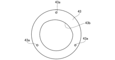
- FIG. 6A is a front view showing a seal member 140 in the second embodiment
- FIG. 6B is a view showing a portion of a cross section taken along line A-A in FIG. 6A.
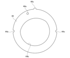
- FIG. 7A is a front view showing the shape of a retaining plate 44 in the second embodiment
- FIG. 7B is a front view showing the shape of a seal plate 45 in the second embodiment
- FIG. 7C is a front view showing the shape of a retaining plate 46 in the second embodiment.
- the same components as those in the first embodiment are given the same reference numerals, and detailed descriptions thereof will be omitted or simplified.
- the ball screw 110 is provided with a seal member 140 that seals the gap between the screw shaft 20 and the nut 30, as in the first embodiment, and the seal member 140 is disposed on the inner circumferential surface of the circular recess 33 of the nut 30.
- a face plate 62 is disposed on the axial end side of the seal member 140, and a metal retaining ring 63 is disposed on the axial end side of the face plate 62.
- the face plate 62 is made of metal, for example, and is disposed to maintain the shape of the seal member 140.
- the face plate hole 62b provided in the face plate 62 is formed to be slightly larger than the cross-sectional shape of the screw shaft 20 at the position where the face plate 62 is disposed.
- the retaining ring 63 is in the shape of a ring having an opening. With the seal member 140 and the face plate 62 disposed on the inner circumferential surface of the circular recess 33, the seal member 140 is fixed to the nut 30 in a pressed state by being fitted to the inner circumferential surface of the circular recess 33.
- the retaining ring 63 is not particularly limited as long as it has a C-shaped configuration, and a concentric retaining ring or a C-shaped retaining ring for shafts can be used. It is particularly preferable to use a concentric retaining ring because it is low cost, has appropriate spring properties, and is easy to work with.
- the seal member 140 has a seal plate 45 and a pair of ring-shaped holding plates 44, 46 that hold the seal plate 45.
- the seal plate 45 has a seal plate hole 45b
- the holding plates 44, 46 also have holding plate holes 44b, 46b that correspond to the shape of the screw shaft 20.
- the seal plate 45 and the holding plates 44, 46 also have protrusions 45c, 44c, 46c, respectively, which serve as alignment when these three plates are stacked.
- recesses 44e, 45e, 46e are provided on both sides that form 90° with respect to the protrusions 45c, 44c, 46c, respectively.
- the holding plates 44, 46 have marking holes 44a, 46a at positions offset from the protrusions 44c, 46c.
- sealing plate 45 and the holding plates 44 and 46 are previously joined together by ultrasonic welding to form an integrated unit.
- welded portions 48 are formed at the interface between the sealing plate 45 and the holding plate 44 and at the interface between the sealing plate 45 and the holding plate 46 at four locations in the circumferential direction of the sealing member 140.
- FIG. 8 is a schematic diagram showing an example of an ultrasonic welding device for integrating the seal members.
- FIG. 9 is a perspective view showing a method of assembling the ball screw according to the second embodiment.
- the lower electrode 71 of the ultrasonic welding device 80 is provided with a plurality of pins 72 protruding upward, and the retaining plate 44, the seal plate 45, and the retaining plate 46 are placed on these pins 72 in this order.
- the seal plate hole 45b and the retaining plate holes 44b, 46b are formed to correspond to the shape of the screw shaft 20 in the phase in which the seal member 140 is arranged.
- the retaining plate 44 and the retaining plate 46 have the same shape of the retaining plate holes 44b, 46b, and by inverting the front and back of one of the retaining plates 46, it is possible to correspond to the shape of the screw shaft 20. Therefore, when stacking the holding plate 44, the sealing plate 45, and the holding plate 46, the positions of the respective convex portions 45c, 44c, 46c and the concave portions 44e, 45e, 46e are aligned, and the mark holes 44a and 46a are positioned so that they do not overlap.
- horn 70 is pressed against them from above in the direction of arrow 74, and ultrasonic waves 73 are generated by horn 70 while pressure is applied to the position corresponding to pin 72.
- welded portions 48 are formed at the interface between sealing plate 45 and holding plate 44 in the pressurized area, and at the interface between sealing plate 45 and holding plate 46, and these are integrated.
- the sealing member 140 and the face plate 62 are inserted in this order into the circular recess 33 formed on the inner circumferential surface of the nut 30.
- the circular recess 33 is provided with a depression 33a, and when inserting the sealing member 140, the insertion position can be determined by aligning these protrusions 44c, 45c, 46c with the depression 33a. Thereafter, the opening 63a of the retaining ring 63 is narrowed while it is inserted into the circular recess 33 and engaged, thereby fixing the sealing member 140 to the inner circumferential surface of the nut 30.
- the gap between the screw shaft 20 and the nut 30 can be sealed by the seal member 140 attached to the axial end of the nut 30.
- the seal plate 45 since a sponge material is used as the material for the seal plate 45, the tightening margin of the seal plate 45 can be securely brought into close contact with the outer circumferential surface of the screw shaft 20, resulting in excellent sealing properties and wear resistance.
- the seal plate 45 and the retaining plates 44 and 46 are previously joined and integrated. Therefore, compared to when the retaining plate 44, seal plate 45, and retaining plate 46 are separate, the insertion of the seal member 140 into the nut 30 can be significantly simplified. Furthermore, when assembling the ball screw 110, the screw shaft 20 is inserted into the nut 30 while rotating the nut 30 or the screw shaft 20, but because the seal member 140 is integrated, it is possible to prevent misalignment between the seal plate 45 and the retaining plates 44 and 46.
- ultrasonic welding is used as a method for joining and integrating the holding plate 44, the sealing plate 45, and the holding plate 46, but the present invention is not limited to this joining method.
- Various joining methods can be used, such as welding by heat, adhesion using adhesives, fastening using fastening materials such as screws or thread, adhesion using adhesive tape, etc., and the structure of the joint will conform to these methods.
- the materials constituting the sealing plate 45 and the holding plates 44, 46 can be the same as those in the first embodiment.
- the holding plates 44, 46 are made of a thermoplastic resin
- the sealing plate 45 is made of a thermosetting resin. It is generally known that ultrasonic welding is easy between the same types of resin materials, but the inventors of the present application have found that ultrasonic welding is suitable for joining the holding plates 44, 46 made of a thermoplastic resin and the sealing plate 45 made of a thermosetting resin.
- the holding plates 44, 46 and the sealing plate 45 are made of the above materials and are joined by ultrasonic welding, the holding plate material melted by ultrasonic waves penetrates into the sponge-like sealing plate 45, resulting in high bonding strength. Also, as shown in Figure 8, they can be easily joined using an ultrasonic welding device, improving manufacturing efficiency. Regardless of the joining method, if the holding plates 44, 46 and the sealing plate 45 are joined in a point pattern in at least two areas, the elasticity of the sealing plate can be well maintained compared to when they are joined in a planar pattern.
- the material constituting the sealing plate 45 can be the same as that in the first embodiment, and in particular, it is preferable to use nitrile butadiene rubber (NBR). In this case, it is preferable to use a material having excellent oil resistance and heat resistance and excellent mechanical strength as the material constituting the holding plates 44, 46. Specifically, it is preferable to use polyacetal resin (POM: Polyoxymethylene) or polybutylene terephthalate (PBT: Polybutylene terephthalate) as the material constituting the holding plates 44, 46, and it is more preferable to use POM.
- POM Polyacetal resin
- PBT Polybutylene terephthalate
- the hardness, density, and bubble state of the sponge material that makes up the sealing plate 45 are the same as in the first embodiment.
- the ball screw seal members 40, 140 according to the first and second embodiments are used in the ball screws 10, 110 according to the first and second embodiments. Details of each seal member are as described above.
- a ball screw comprising: a threaded shaft having a helical thread groove formed on an outer circumferential surface thereof; a nut having a helical thread groove formed on an inner circumferential surface thereof; a plurality of balls rolling on a load track defined by the thread groove of the threaded shaft and the thread groove of the nut; and a seal member attached to at least one axial end of the nut and sealing a gap between the threaded shaft and the nut, a sealing member that has a ring-shaped sealing plate having an inner surface that contacts the outer surface of the screw shaft, and a pair of ring-shaped retaining plates that sandwich the sealing plate, and the sealing plate is made of a sponge material.
- the shape of the seal plate can be maintained and the inner peripheral surface of the seal plate can be reliably brought into close contact with the outer peripheral surface of the screw shaft, so that leakage of lubricant from inside the nut can be suppressed and intrusion of foreign matter from the outside can be prevented, thereby obtaining a ball screw with excellent sealing properties. Also, because the seal plate absorbs the lubricant on the surface of the screw groove, a ball screw with reduced wear of the seal plate can be obtained.
- the seal plate is made of a material including at least one selected from the group consisting of nitrile butadiene rubber, hydrogenated nitrile rubber, ethylene propylene rubber, ethylene propylene diene rubber, vinyl methyl silicone rubber, acrylic rubber, and fluororubber.
- the sealing plate is made of a material having excellent heat resistance and chemical resistance, so that the sealing plate has excellent durability and the sealing performance of the sealing member can be further improved.
- the sealing plate is made of a material containing at least one selected from the group consisting of resin and elastomer. According to this configuration, the sealing plate is made of a material having excellent heat resistance and chemical resistance, so that the sealing plate has excellent durability and the sealing performance of the sealing member can be further improved.
- a sealing member for a ball screw characterized in that it is used in the ball screw according to any one of (1) to (7).
- the shape of the sealing plate can be maintained and the inner surface of the sealing plate can be reliably adhered to the outer surface of the screw shaft, thereby obtaining excellent sealing properties and reducing wear on the sealing plate.
Landscapes
- Engineering & Computer Science (AREA)
- General Engineering & Computer Science (AREA)
- Mechanical Engineering (AREA)
- Transmission Devices (AREA)
Priority Applications (1)
| Application Number | Priority Date | Filing Date | Title |
|---|---|---|---|
| JP2025513725A JPWO2025084269A1 (https=) | 2023-10-20 | 2024-10-15 |
Applications Claiming Priority (2)
| Application Number | Priority Date | Filing Date | Title |
|---|---|---|---|
| JP2023-181063 | 2023-10-20 | ||
| JP2023181063 | 2023-10-20 |
Publications (1)
| Publication Number | Publication Date |
|---|---|
| WO2025084269A1 true WO2025084269A1 (ja) | 2025-04-24 |
Family
ID=95448396
Family Applications (1)
| Application Number | Title | Priority Date | Filing Date |
|---|---|---|---|
| PCT/JP2024/036617 Pending WO2025084269A1 (ja) | 2023-10-20 | 2024-10-15 | ボールねじ及びボールねじ用シール部品 |
Country Status (3)
| Country | Link |
|---|---|
| JP (1) | JPWO2025084269A1 (https=) |
| TW (1) | TWI909760B (https=) |
| WO (1) | WO2025084269A1 (https=) |
Citations (4)
| Publication number | Priority date | Publication date | Assignee | Title |
|---|---|---|---|---|
| JP2002364726A (ja) * | 2001-04-05 | 2002-12-18 | Thk Co Ltd | ボールねじ用シール及びこのボールねじ用シールを用いたボールねじ |
| JP2008128324A (ja) * | 2006-11-20 | 2008-06-05 | Nsk Ltd | 直線運動装置及び直線運動装置用シール部材の製造方法 |
| JP2017003112A (ja) * | 2015-06-12 | 2017-01-05 | 日本精工株式会社 | 直動装置 |
| JP2020093513A (ja) * | 2018-12-04 | 2020-06-18 | 日本発條株式会社 | 発泡シール材、および発泡シール材の製造方法 |
Family Cites Families (7)
| Publication number | Priority date | Publication date | Assignee | Title |
|---|---|---|---|---|
| JPH02105659U (https=) * | 1989-02-09 | 1990-08-22 | ||
| JP2004347922A (ja) * | 2003-05-23 | 2004-12-09 | Fuji Photo Film Co Ltd | 感光材料処理装置 |
| JP2007321845A (ja) * | 2006-05-31 | 2007-12-13 | Ntn Corp | シール部材および該シール部材を用いた軸受 |
| JP2010088148A (ja) * | 2008-09-29 | 2010-04-15 | Sekisui Chem Co Ltd | 止水構造 |
| JP2013164116A (ja) * | 2012-02-10 | 2013-08-22 | Nsk Ltd | ボールねじ装置 |
| JP6127015B2 (ja) * | 2014-04-28 | 2017-05-10 | 貞晋 大工 | 発泡ゴムピグおよびその製造方法 |
| JP6400176B2 (ja) * | 2017-01-12 | 2018-10-03 | Thk株式会社 | ボールねじ装置のシール部材 |
-
2024
- 2024-10-15 WO PCT/JP2024/036617 patent/WO2025084269A1/ja active Pending
- 2024-10-15 JP JP2025513725A patent/JPWO2025084269A1/ja active Pending
- 2024-10-18 TW TW113139705A patent/TWI909760B/zh active
Patent Citations (4)
| Publication number | Priority date | Publication date | Assignee | Title |
|---|---|---|---|---|
| JP2002364726A (ja) * | 2001-04-05 | 2002-12-18 | Thk Co Ltd | ボールねじ用シール及びこのボールねじ用シールを用いたボールねじ |
| JP2008128324A (ja) * | 2006-11-20 | 2008-06-05 | Nsk Ltd | 直線運動装置及び直線運動装置用シール部材の製造方法 |
| JP2017003112A (ja) * | 2015-06-12 | 2017-01-05 | 日本精工株式会社 | 直動装置 |
| JP2020093513A (ja) * | 2018-12-04 | 2020-06-18 | 日本発條株式会社 | 発泡シール材、および発泡シール材の製造方法 |
Also Published As
| Publication number | Publication date |
|---|---|
| TW202526200A (zh) | 2025-07-01 |
| JPWO2025084269A1 (https=) | 2025-04-24 |
| TWI909760B (zh) | 2025-12-21 |
Similar Documents
| Publication | Publication Date | Title |
|---|---|---|
| JP5037682B2 (ja) | リップタイプシール | |
| JP5256204B2 (ja) | 転動装置 | |
| US6565096B2 (en) | Lip type seal | |
| TWI683969B (zh) | 滾珠螺桿裝置的密封構件 | |
| TW201137260A (en) | Seal chain | |
| JP5039551B2 (ja) | メカニカルシール装置 | |
| JP2012092976A (ja) | 回転軸シール | |
| WO2025084269A1 (ja) | ボールねじ及びボールねじ用シール部品 | |
| JP5076638B2 (ja) | ボールねじ装置 | |
| JP4538238B2 (ja) | ガスケット | |
| JP2002159343A (ja) | ブラシ型シール装置 | |
| JP4244585B2 (ja) | 密封装置 | |
| JPH10267134A (ja) | 密封装置及び密封装置の製造方法 | |
| JP4106753B2 (ja) | 密封装置 | |
| JP7691296B2 (ja) | 密封装置 | |
| JP2005054827A (ja) | 密封装置 | |
| JP2009079610A (ja) | 転がり軸受用密封装置 | |
| JP6566040B2 (ja) | シールリング | |
| EP4571152A1 (en) | Secondary seal | |
| JP2006002894A (ja) | シールワッシャ | |
| JPH02204139A (ja) | シートトラック | |
| JPH0446137Y2 (https=) | ||
| GB2295425A (en) | Rolling bearing with seals | |
| JP4732263B2 (ja) | ボールねじの潤滑シール装置 | |
| JPH0534376Y2 (https=) |
Legal Events
| Date | Code | Title | Description |
|---|---|---|---|
| ENP | Entry into the national phase |
Ref document number: 2025513725 Country of ref document: JP Kind code of ref document: A |
|
| WWE | Wipo information: entry into national phase |
Ref document number: 2025513725 Country of ref document: JP |
|
| 121 | Ep: the epo has been informed by wipo that ep was designated in this application |
Ref document number: 24879693 Country of ref document: EP Kind code of ref document: A1 |