WO2025083776A1 - カバー、シール構造および産業機械 - Google Patents
カバー、シール構造および産業機械 Download PDFInfo
- Publication number
- WO2025083776A1 WO2025083776A1 PCT/JP2023/037524 JP2023037524W WO2025083776A1 WO 2025083776 A1 WO2025083776 A1 WO 2025083776A1 JP 2023037524 W JP2023037524 W JP 2023037524W WO 2025083776 A1 WO2025083776 A1 WO 2025083776A1
- Authority
- WO
- WIPO (PCT)
- Prior art keywords
- seating surface
- cover
- mating surface
- industrial machine
- drain port
- Prior art date
- Legal status (The legal status is an assumption and is not a legal conclusion. Google has not performed a legal analysis and makes no representation as to the accuracy of the status listed.)
- Pending
Links
Images


Classifications
-
- B—PERFORMING OPERATIONS; TRANSPORTING
- B23—MACHINE TOOLS; METAL-WORKING NOT OTHERWISE PROVIDED FOR
- B23Q—DETAILS, COMPONENTS, OR ACCESSORIES FOR MACHINE TOOLS, e.g. ARRANGEMENTS FOR COPYING OR CONTROLLING; MACHINE TOOLS IN GENERAL CHARACTERISED BY THE CONSTRUCTION OF PARTICULAR DETAILS OR COMPONENTS; COMBINATIONS OR ASSOCIATIONS OF METAL-WORKING MACHINES, NOT DIRECTED TO A PARTICULAR RESULT
- B23Q11/00—Accessories fitted to machine tools for keeping tools or parts of the machine in good working condition or for cooling work; Safety devices specially combined with or arranged in, or specially adapted for use in connection with, machine tools
- B23Q11/08—Protective coverings for parts of machine tools; Splash guards
-
- B—PERFORMING OPERATIONS; TRANSPORTING
- B23—MACHINE TOOLS; METAL-WORKING NOT OTHERWISE PROVIDED FOR
- B23Q—DETAILS, COMPONENTS, OR ACCESSORIES FOR MACHINE TOOLS, e.g. ARRANGEMENTS FOR COPYING OR CONTROLLING; MACHINE TOOLS IN GENERAL CHARACTERISED BY THE CONSTRUCTION OF PARTICULAR DETAILS OR COMPONENTS; COMBINATIONS OR ASSOCIATIONS OF METAL-WORKING MACHINES, NOT DIRECTED TO A PARTICULAR RESULT
- B23Q11/00—Accessories fitted to machine tools for keeping tools or parts of the machine in good working condition or for cooling work; Safety devices specially combined with or arranged in, or specially adapted for use in connection with, machine tools
- B23Q11/12—Arrangements for cooling or lubricating parts of the machine
-
- B—PERFORMING OPERATIONS; TRANSPORTING
- B25—HAND TOOLS; PORTABLE POWER-DRIVEN TOOLS; MANIPULATORS
- B25J—MANIPULATORS; CHAMBERS PROVIDED WITH MANIPULATION DEVICES
- B25J19/00—Accessories fitted to manipulators, e.g. for monitoring, for viewing; Safety devices combined with or specially adapted for use in connection with manipulators
-
- F—MECHANICAL ENGINEERING; LIGHTING; HEATING; WEAPONS; BLASTING
- F16—ENGINEERING ELEMENTS AND UNITS; GENERAL MEASURES FOR PRODUCING AND MAINTAINING EFFECTIVE FUNCTIONING OF MACHINES OR INSTALLATIONS; THERMAL INSULATION IN GENERAL
- F16H—GEARING
- F16H57/00—General details of gearing
- F16H57/04—Features relating to lubrication or cooling or heating
-
- F—MECHANICAL ENGINEERING; LIGHTING; HEATING; WEAPONS; BLASTING
- F16—ENGINEERING ELEMENTS AND UNITS; GENERAL MEASURES FOR PRODUCING AND MAINTAINING EFFECTIVE FUNCTIONING OF MACHINES OR INSTALLATIONS; THERMAL INSULATION IN GENERAL
- F16N—LUBRICATING
- F16N31/00—Means for collecting, retaining, or draining-off lubricant in or on machines or apparatus
-
- F—MECHANICAL ENGINEERING; LIGHTING; HEATING; WEAPONS; BLASTING
- F16—ENGINEERING ELEMENTS AND UNITS; GENERAL MEASURES FOR PRODUCING AND MAINTAINING EFFECTIVE FUNCTIONING OF MACHINES OR INSTALLATIONS; THERMAL INSULATION IN GENERAL
- F16N—LUBRICATING
- F16N33/00—Mechanical arrangements for cleaning lubricating equipment; Special racks or the like for use in draining lubricant from machine parts
Definitions
- This disclosure relates to a cover, a seal structure, and an industrial machine.
- a lubricant discharge structure in which a lubricant such as grease is injected into a sealed lubricated part such as a reducer, and the used lubricant is discharged from a grease drain port (see, for example, Patent Document 1).
- This lubricant discharge structure includes a tube connected to a grease drain port, a plug that releasably closes the end of the tube, and a cover that houses the tube while it is connected to the grease drain port when the lubricant is not being replaced. By providing a hole in the cover and leaving the plug at the end of the tube exposed from the cover, the plug can be removed to discharge the lubricant from the open end of the tube without removing the cover.
- this structure requires the installation of a tube, a connecting part for connecting the tube to the grease outlet, a fitting for removably attaching the plug to the end of the tube, and the work of installing the tube. Therefore, it is desirable to keep the number of parts, processing labor, and assembly labor low, and to perform the replacement work easily at low cost and without contaminating the inside with the lubricant discharged during replacement.
- One aspect of the present disclosure is a cover that releasably closes the space around a grease drain port for discharging lubricant from a sealed lubricated part of an industrial machine body, and when attached to the industrial machine body, the cover includes a through hole that exposes the grease drain port, a first mating surface that is provided around the entire circumference of the through hole and faces a first seating surface that is provided around the entire circumference of the grease drain port, and a second mating surface that is disposed around the entire circumference facing a second seating surface that is provided in a position that completely surrounds the outside of the first seating surface, and the first mating surface is capable of sealing the entire circumference of the through hole with a first seal member that is compressed between the first seating surface and the first mating surface.
- a seal structure that uses a cover to releasably close the space around a grease drain port for discharging lubricant from a sealed lubricated part of an industrial machine body
- the seal structure comprising: a first seating surface provided on the industrial machine body and provided around the entire periphery of the grease drain port; a second seating surface provided in a position surrounding the outside of the first seating surface around the entire periphery; a through hole provided on the cover and exposing the grease drain port when attached to the industrial machine body; a first mating surface disposed opposite the first seating surface around the entire periphery; and a first seal member that is compressed between the first mating surface and the first seating surface to seal the entire periphery of the through hole.
- an industrial machine comprising an industrial machine body, a cover attached to the industrial machine body, and a first seal member sandwiched between the cover and the industrial machine body, the industrial machine body comprising a first seating surface provided around a grease drain port for discharging lubricant from a sealed lubricated part, and a second seating surface provided in a position surrounding the outside of the first seating surface around the entire circumference, the cover, when attached to the industrial machine body, comprising a through hole exposing the grease drain port, a first mating surface disposed opposite the first seating surface around the entire circumference, and a second mating surface disposed opposite the second seating surface around the entire circumference, and the first seal member is compressed between the first mating surface and the first seating surface, thereby being able to seal the periphery of the through hole around the entire circumference.
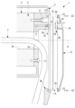
- FIG. 1 is a partial vertical cross-sectional view illustrating a cover, a seal structure, and an industrial machine according to an embodiment of the present disclosure.
- FIG. 2 is a partial side view of the cover and industrial machine of FIG. 1 .
- FIG. 2 is a partial side view of the industrial machine body with the cover of FIG. 1 attached.
- FIG. 3 is a rear view of the cover of FIG. 2 .
- FIG. 2 is a partial exploded vertical cross-sectional view illustrating the cover, the seal structure, and the industrial machine of FIG. 1.
- FIG. 2 is a partial vertical cross-sectional view illustrating a grease draining operation in the industrial machine of FIG. 1 .
- a cover 12, a seal structure 30, and an industrial machine according to one embodiment of the present disclosure will be described below with reference to the drawings.
- a robot 1 will be described as an example of industrial machinery.
- the industrial machinery may be any industrial machinery such as a robot 1, a machine tool, or an injection molding machine that has a sealed lubricated part 4 such as a reducer 3 and a grease drain port 5a for discharging used lubricant from the lubricated part 4.
- the robot 1 has a rotating body (industrial machine body) 2 supported rotatably about a vertical axis with respect to a base (not shown) that is fixed to an installation surface such as a floor.
- the robot 1 also has a first arm (not shown) supported rotatably about a horizontal axis A with respect to the rotating body 2.
- a reduction gear 3 is provided between the rotating body 2 and the first arm, which reduces the rotation of a motor (not shown) and rotates the first arm around the horizontal axis A relative to the rotating body 2.
- the reduction gear 3 has an internal reduction mechanism (not shown) and is filled with a lubricant such as grease to lubricate the reduction mechanism.
- a lubricant such as grease to lubricate the reduction mechanism.
- the reduction gear 3 forms a lubricated part 4 that is sealed by its case, the rotating body 2, and the first arm.
- the rotating body 2 is provided with a grease drain hole 5 that connects the inside of the reduction gear 3 with the outside of the robot 1.
- the grease drain port 5a at the tip of the grease drain hole 5 opens to the vertical side of the rotating body 2 and is closed by a removable plug 6 under normal conditions.
- the grease drain hole 5 is provided inside the radial outer shape of the reduction gear 3 and at a position higher than the horizontal axis A, for example as shown in Figures 1 and 2. This position corresponds to the recommended lubricant filling level in the reduction gear 3.
- the rotating body 2 and the reduction gear 3 are provided with central openings 2a, 3a that penetrate along the horizontal axis A in an area including the horizontal axis A. As shown in FIG. 1, for example, the filament 7 rising from the base side is passed through the central openings 2a, 3a.
- wire body 7 Although only one wire body 7 is shown in FIG. 1, multiple wire bodies may be provided, for example, a cable for driving a motor arranged at the tip side of the first arm, or a tube for supplying water or air.
- the wire body 7 is fixed to the rotating body 2 at a midpoint in the longitudinal direction by a fastener such as a nylon band (not shown), and then wired so as to pass through the central openings 2a and 3a.
- the rotating body 2 has seats (first and second seats) 8, 9 for mounting a cover 12, which will be described later.
- the first seat 8 is a machined flat surface that is provided in a position that completely surrounds the grease drain port 5a and extends in the vertical direction.
- the second seat 9 is also a machined flat surface that extends in the vertical direction and is formed in an annular shape, with its inner edge forming an opening 10 that opens the internal space M of the rotating body 2 to the outside.
- the opening 10 contains a space leading to the base, mounting bolts 11 for attaching the reducer 3 to the rotating body 2, and a central opening 2a.
- the installation of the reducer 3 to the rotating body 2 and wiring of the wires 7 can be performed through the opening 10 that opens to the inside of the second seating surface 9.
- first seating surface 8 and the second seating surface 9 are provided on the same plane and are continuous with each other as shown in FIG. 3.
- the second seating surface 9 has a plurality of screw holes 13 spaced apart in the circumferential direction for attaching the cover 12.
- the robot 1 further includes a cover 12 according to this embodiment that is attached to the rotating body 2 , and a first seal member 14 and a second seal member 15 that seal between the cover 12 and the rotating body 2 .
- the cover 12 includes a through hole 16 that exposes the grease drain port 5a when attached to the rotating body 2, a first mating surface 17 that is disposed opposite the first seating surface 8 over the entire circumference, and a second mating surface 18 that is disposed opposite the second seating surface 9 over the entire circumference.
- the first mating surface 17 and the second mating surface 18 may be unmachined surfaces obtained by manufacturing the cover 12 by die casting, or machined surfaces formed by machining the cover 12 may be used.
- the through hole 16 has a shape that gradually widens from the first mating surface 17 side of the cover 12 toward the outer surface side.
- the first mating surface 17 and the second mating surface 18 are separate but provided on the same plane.
- the first mating surface 17 is provided with a first annular seal groove 19 that completely surrounds the periphery of the through hole 16.
- the second mating surface 18 is provided with a plurality of bolt holes 21 that are provided at positions corresponding to the screw holes 13 of the second seating surface 9 when the second mating surface 18 is disposed opposite the second seating surface 9.
- the second mating surface 18 is also provided with a second annular seal groove 20 that is formed along the inner edge, closer to the inner edge of the second mating surface 18 than all of the bolt holes 21.
- the first seal member 14 is a rubber O-ring housed in the first seal groove 19 .
- the second seal member 15 is an annular seal member having the same cross section and made of the same material as the O-ring accommodated in the second seal groove 20 and is preformed to fit the shape of the second seal groove 20 .
- the seal structure 30 includes a first seating surface 8 and a second seating surface 9 provided on the rotating body 2, a through hole 16 provided on the cover 12, a first mating surface 17 and a second mating surface 18, and a first seal member 14 and a second seal member 15.
- the cover 12 by removing the cover 12 from the rotating body 2, the internal space M of the rotating body 2 is opened by the opening 10, so that installation and removal of the reducer 3, wiring work of the wire body 7, etc. can be performed through the opening 10. Furthermore, by attaching the cover 12 of this embodiment to the rotating body 2, the opening 10 can be blocked to define the internal space M in an airtight state, and the space continuing to the base placed within the opening 10 and the internal structure such as the filament 7 can be hidden.
- the first seal member 14 is accommodated in the first seal groove 19 provided in the cover 12, and the second seal member 15 is accommodated in the second seal groove 20.
- the first seal member 14 and the second seal member 15 are held in place in the first seal groove 19 and the second seal groove 20, respectively, by their elasticity or by the adhesiveness of grease or the like that is additionally used.
- the first mating surface 17 and the second mating surface 18 of the cover 12 are placed opposite the first seating surface 8 and the second seating surface 9 of the rotating body 2, respectively, and the bolts 22 that have passed through the bolt holes 21 of the cover 12 are fastened to the corresponding screw holes 13.
- the first seal member 14 is compressed between the first seal groove 19 and the first seating surface 8, and the second seal member 15 is compressed between the second seal groove 20 and the second seating surface 9.
- the plug 6 is removed from the grease drain port 5a via the through hole 16, and new lubricant is filled through the grease supply port (not shown).
- the lubricant in the lubricated parts 4 is replaced with new lubricant, and the lubricant is filled up to the specified filling level.
- the gap between the rotating body 2 and the cover 12 around the grease drain port 5a is sealed all around by the first seal member 14. Therefore, the lubricant pushed out from the grease drain port 5a does not enter the internal space M of the rotating body 2 through the gap between the rotating body 2 and the cover 12, but is all discharged to the outside through the through hole 16, as shown by the arrow.
- the periphery of the grease drain port 5a is directly sealed by the first seal member 14 disposed between the first seat surface 8 of the rotating body 2 and the first mating surface 17 of the cover 12. This eliminates the need for the tube, the connection parts for connecting the tube to the grease drain port 5a, and the fittings for removably attaching the plug 6 to the tip of the tube, as was previously required, and the installation work for the tube, etc.
- the lubricant can be easily replaced without contaminating the inside of the rotating body 2, for example, the wire body 7, with the lubricant discharged during replacement.
- the second seal member 15 can be omitted in applications that do not require high sealing performance of the internal space M of the rotating body 2. For example, in a robot used in an environment with little mist or dust, the second seal member 15 is unnecessary, and costs due to excessive protection can be prevented from increasing.
- the first and second bearing surfaces 8 and 9 of the rotating body 2 are disposed in the same plane, which facilitates machining.
- the first and second mating surfaces 17 and 18 of the cover 12 are disposed in the same plane, which facilitates machining.
- the through hole 16 of the cover 12 has a shape that widens outward, the plug 6 can be easily removed from the outside, and the lubricant discharged from the grease drain port 5a can be easily discharged and wiped off.
- the first and second seating surfaces 8 and 9 of the rotating body 2 and the first and second mating surfaces 17 and 18 of the cover 12 do not have to be located on the same plane. As long as the first and second seating surfaces 17 and 18 are located in close contact with each other when the cover 12 is attached to the rotating body 2, they do not have to be located on the same plane.
- a cover 12 having both a first seal groove 19 and a second seal groove 20 is used, but instead, only the first seal groove 19 may be provided.
- the second seal groove 20 for mounting the second seal member 15 may not be provided at all.
- an O-ring or an equivalent sealing member is used as the first sealing member 14 and the second sealing member 15, but a flat gasket may be used instead.
- a flat gasket may be used instead of an O-ring.
- the second sealing groove 20 of the cover 12 may be omitted.
- gaskets are used as both the first sealing member 14 and the second sealing member 15, both the first sealing groove 19 and the second sealing groove 20 may be omitted.
- first seal groove 19 is provided on the first mating surface 17 of the cover 12 and the second seal groove 20 is provided on the second mating surface 18
- first seal groove 19 may instead be provided on the first seating surface 8 of the rotating body 2 and the second seal groove 20 on the second seating surface 9.
- the grease drain port 5a in the reducer 3 between the rotating body 2 and the first arm has been given as an example, but it may also be applied to lubricated parts such as reducers and gear boxes in other joints. Also, while a vertical 6-axis articulated robot has been given as an example of industrial machinery, it may also be applied to other types of robots, machine tools, injection molding machines, and other industrial machinery.
- a cover that releasably closes a space around a grease drain port for discharging a lubricant from a sealed lubricated part of an industrial machine body, a through hole for exposing the grease drain port when the bearing is attached to the industrial machine body, a first mating surface provided around the entire circumference of the through hole and opposed to a first seating surface provided around the entire circumference of the grease drain port, and a second mating surface disposed opposite to a second seating surface provided at a position surrounding the outer side of the first seating surface over the entire circumference,
- the cover is capable of sealing the entire periphery of the through hole by a first seal member compressed between the first mating surface and the first seating surface.
- the second seating surface is provided with a plurality of screw holes spaced apart in a circumferential direction
- the cover according to any one of claims 1 to 3, wherein the second mating surface is provided with a plurality of bolt holes that are provided at positions corresponding to the screw holes and through which bolts are passed.
- a seal structure in which a space around a grease drain port for discharging a lubricant from a sealed lubricated part of an industrial machine body is releasably closed by a cover, a first seating surface provided on the industrial machine body and entirely around the grease drain port, and a second seating surface provided at a position surrounding the outside of the first seating surface entirely; a through hole that is provided in the cover and exposes the grease drain port in a state where the cover is attached to the industrial machine body, a first mating surface that is arranged to face the first seating surface over an entire circumference, and a second mating surface that is arranged to face the second seating surface over an entire circumference; a first seal member that is compressed between the first mating surface and the first seating surface to seal the entire periphery of the through hole.
- the second seating surface is provided with a plurality of screw holes spaced apart in a circumferential direction, 10.
- the industrial machine includes an industrial machine body, a cover attached to the industrial machine body, and a first seal member sandwiched between the cover and the industrial machine body, the industrial machine body comprises a first seating surface provided around a grease drain port for discharging lubricant from a sealed lubricated part, and a second seating surface provided at a position surrounding the outside of the first seating surface over the entire circumference, the cover includes, when attached to the industrial machine body, a through hole for exposing the grease drain port, a first mating surface disposed opposite the first seating surface over an entire periphery, and a second mating surface disposed opposite the second seating surface over an entire periphery, The first seal member is compressed between the first mating surface and the first seating surface, thereby sealing the entire periphery of the through hole.
Landscapes
- Engineering & Computer Science (AREA)
- General Engineering & Computer Science (AREA)
- Mechanical Engineering (AREA)
- Robotics (AREA)
- Manipulator (AREA)
- Pressure Vessels And Lids Thereof (AREA)
- General Details Of Gearings (AREA)
- Sealing Of Bearings (AREA)
- Sealing Devices (AREA)
Priority Applications (3)
| Application Number | Priority Date | Filing Date | Title |
|---|---|---|---|
| JP2024505596A JP7481599B1 (ja) | 2023-10-17 | 2023-10-17 | カバー、シール構造および産業機械 |
| PCT/JP2023/037524 WO2025083776A1 (ja) | 2023-10-17 | 2023-10-17 | カバー、シール構造および産業機械 |
| TW113137650A TW202517393A (zh) | 2023-10-17 | 2024-10-01 | 外罩、油封構造以及工業機械 |
Applications Claiming Priority (1)
| Application Number | Priority Date | Filing Date | Title |
|---|---|---|---|
| PCT/JP2023/037524 WO2025083776A1 (ja) | 2023-10-17 | 2023-10-17 | カバー、シール構造および産業機械 |
Publications (1)
| Publication Number | Publication Date |
|---|---|
| WO2025083776A1 true WO2025083776A1 (ja) | 2025-04-24 |
Family
ID=90925998
Family Applications (1)
| Application Number | Title | Priority Date | Filing Date |
|---|---|---|---|
| PCT/JP2023/037524 Pending WO2025083776A1 (ja) | 2023-10-17 | 2023-10-17 | カバー、シール構造および産業機械 |
Country Status (3)
| Country | Link |
|---|---|
| JP (1) | JP7481599B1 (https=) |
| TW (1) | TW202517393A (https=) |
| WO (1) | WO2025083776A1 (https=) |
Citations (9)
| Publication number | Priority date | Publication date | Assignee | Title |
|---|---|---|---|---|
| JPH11254377A (ja) * | 1998-03-10 | 1999-09-21 | Denso Corp | ロボット |
| JP2005177914A (ja) * | 2003-12-18 | 2005-07-07 | Fanuc Ltd | ロボット、工作機械又は射出成形機における潤滑剤排出構造 |
| JP2016017300A (ja) * | 2014-07-07 | 2016-02-01 | 日立建機株式会社 | 作業車両用回転電機の給脂装置 |
| CN107289115A (zh) * | 2016-04-01 | 2017-10-24 | 舍弗勒技术股份两合公司 | 轮内驱动总成 |
| JP2020116716A (ja) * | 2019-01-28 | 2020-08-06 | ファナック株式会社 | ロボット |
| CN113007332A (zh) * | 2021-02-24 | 2021-06-22 | 陕西法士特齿轮有限责任公司 | 一种变速器润滑冷却系统 |
| JP2022085273A (ja) * | 2020-11-27 | 2022-06-08 | 株式会社安川電機 | 潤滑剤供給システム、潤滑剤の供給方法、産業機械の製造方法、及び多関節ロボットの製造方法 |
| JP2022155816A (ja) * | 2021-03-31 | 2022-10-14 | 住友重機械工業株式会社 | 親機械、潤滑剤の封入方法、潤滑剤セット |
| WO2023275972A1 (ja) * | 2021-06-29 | 2023-01-05 | ファナック株式会社 | 潤滑材バス構造およびロボット |
Family Cites Families (2)
| Publication number | Priority date | Publication date | Assignee | Title |
|---|---|---|---|---|
| JP6072707B2 (ja) * | 2014-02-04 | 2017-02-01 | 本田技研工業株式会社 | 変速機のベアリング潤滑構造 |
| CN207261144U (zh) * | 2017-08-30 | 2018-04-20 | 河南柴油机重工有限责任公司 | 一种高压共轨柴油机驱动共轨泵中间齿轮安装装置 |
-
2023
- 2023-10-17 JP JP2024505596A patent/JP7481599B1/ja active Active
- 2023-10-17 WO PCT/JP2023/037524 patent/WO2025083776A1/ja active Pending
-
2024
- 2024-10-01 TW TW113137650A patent/TW202517393A/zh unknown
Patent Citations (9)
| Publication number | Priority date | Publication date | Assignee | Title |
|---|---|---|---|---|
| JPH11254377A (ja) * | 1998-03-10 | 1999-09-21 | Denso Corp | ロボット |
| JP2005177914A (ja) * | 2003-12-18 | 2005-07-07 | Fanuc Ltd | ロボット、工作機械又は射出成形機における潤滑剤排出構造 |
| JP2016017300A (ja) * | 2014-07-07 | 2016-02-01 | 日立建機株式会社 | 作業車両用回転電機の給脂装置 |
| CN107289115A (zh) * | 2016-04-01 | 2017-10-24 | 舍弗勒技术股份两合公司 | 轮内驱动总成 |
| JP2020116716A (ja) * | 2019-01-28 | 2020-08-06 | ファナック株式会社 | ロボット |
| JP2022085273A (ja) * | 2020-11-27 | 2022-06-08 | 株式会社安川電機 | 潤滑剤供給システム、潤滑剤の供給方法、産業機械の製造方法、及び多関節ロボットの製造方法 |
| CN113007332A (zh) * | 2021-02-24 | 2021-06-22 | 陕西法士特齿轮有限责任公司 | 一种变速器润滑冷却系统 |
| JP2022155816A (ja) * | 2021-03-31 | 2022-10-14 | 住友重機械工業株式会社 | 親機械、潤滑剤の封入方法、潤滑剤セット |
| WO2023275972A1 (ja) * | 2021-06-29 | 2023-01-05 | ファナック株式会社 | 潤滑材バス構造およびロボット |
Also Published As
| Publication number | Publication date |
|---|---|
| JP7481599B1 (ja) | 2024-05-10 |
| JPWO2025083776A1 (https=) | 2025-04-24 |
| TW202517393A (zh) | 2025-05-01 |
Similar Documents
| Publication | Publication Date | Title |
|---|---|---|
| CN111482987B (zh) | 机器人 | |
| KR101712531B1 (ko) | 건설 기계의 선회 장치 | |
| CN111409111B (zh) | 工业机器人、机械臂、关节结构及其装配方法 | |
| US8096911B2 (en) | Eccentric oscillating gear mechanism and industrial robot joint construction using the same | |
| JP6736679B2 (ja) | 減速機付きモータ及び多関節ロボット | |
| CN111843982A (zh) | 工业用机器人及其可达半径延长方法 | |
| JPH11254377A (ja) | ロボット | |
| US5727095A (en) | Bearing seal with uniform fluid purge | |
| JP2022503732A (ja) | 減速機、減速モータ及びロボット | |
| JP7481599B1 (ja) | カバー、シール構造および産業機械 | |
| KR101110047B1 (ko) | 공구 매거진용 기어드모터 | |
| US6217219B1 (en) | Bearing seal with uniform fluid purge | |
| US7090220B2 (en) | Cartridge-type bearing seal for machine tool spindle | |
| JP2002018678A (ja) | インデックステーブル | |
| CN115087523B (zh) | 使多个构造部相对地旋转的驱动部的构造和具备关节部的机器人 | |
| US11285622B2 (en) | Wrist structure of robot, and robot | |
| CN118382515A (zh) | 包括密封盖子的工业机器人 | |
| WO2020030296A1 (en) | Bearing device and construction machine | |
| JPH11270698A (ja) | メカニカルシールの組付け方法及び組付け構造 | |
| US20180119795A1 (en) | Lubricant retention shield | |
| JP6355245B2 (ja) | 作業車両用回転電機の給脂装置 | |
| JP3007033B2 (ja) | 工作機械のシール構造 | |
| JP2002349490A (ja) | 流体機械の車室構造 | |
| RU2153459C2 (ru) | Устройство для подвески и поворота рабочего органа грузоподъемного средства | |
| KR200191835Y1 (ko) | 전선단락 및 에어관로의 꼬임방지용 감속기형 서보회전장치 |
Legal Events
| Date | Code | Title | Description |
|---|---|---|---|
| ENP | Entry into the national phase |
Ref document number: 2024505596 Country of ref document: JP Kind code of ref document: A |
|
| WWE | Wipo information: entry into national phase |
Ref document number: 2024505596 Country of ref document: JP |
|
| 121 | Ep: the epo has been informed by wipo that ep was designated in this application |
Ref document number: 23956029 Country of ref document: EP Kind code of ref document: A1 |