WO2025079142A1 - 圧延機の板厚制御装置 - Google Patents
圧延機の板厚制御装置 Download PDFInfo
- Publication number
- WO2025079142A1 WO2025079142A1 PCT/JP2023/036763 JP2023036763W WO2025079142A1 WO 2025079142 A1 WO2025079142 A1 WO 2025079142A1 JP 2023036763 W JP2023036763 W JP 2023036763W WO 2025079142 A1 WO2025079142 A1 WO 2025079142A1
- Authority
- WO
- WIPO (PCT)
- Prior art keywords
- plate thickness
- thickness deviation
- rolling mill
- reel
- calculation unit
- Prior art date
- Legal status (The legal status is an assumption and is not a legal conclusion. Google has not performed a legal analysis and makes no representation as to the accuracy of the status listed.)
- Pending
Links
Images


Classifications
-
- B—PERFORMING OPERATIONS; TRANSPORTING
- B21—MECHANICAL METAL-WORKING WITHOUT ESSENTIALLY REMOVING MATERIAL; PUNCHING METAL
- B21B—ROLLING OF METAL
- B21B37/00—Control devices or methods specially adapted for metal-rolling mills or the work produced thereby
-
- B—PERFORMING OPERATIONS; TRANSPORTING
- B21—MECHANICAL METAL-WORKING WITHOUT ESSENTIALLY REMOVING MATERIAL; PUNCHING METAL
- B21B—ROLLING OF METAL
- B21B37/00—Control devices or methods specially adapted for metal-rolling mills or the work produced thereby
- B21B37/16—Control of thickness, width, diameter or other transverse dimensions
- B21B37/18—Automatic gauge control
-
- B—PERFORMING OPERATIONS; TRANSPORTING
- B21—MECHANICAL METAL-WORKING WITHOUT ESSENTIALLY REMOVING MATERIAL; PUNCHING METAL
- B21C—MANUFACTURE OF METAL SHEETS, WIRE, RODS, TUBES, PROFILES OR LIKE SEMI-MANUFACTURED PRODUCTS OTHERWISE THAN BY ROLLING; AUXILIARY OPERATIONS USED IN CONNECTION WITH METAL-WORKING WITHOUT ESSENTIALLY REMOVING MATERIAL
- B21C47/00—Winding-up, coiling or winding-off metal wire, metal band or other flexible metal material characterised by features relevant to metal processing only
-
- B—PERFORMING OPERATIONS; TRANSPORTING
- B21—MECHANICAL METAL-WORKING WITHOUT ESSENTIALLY REMOVING MATERIAL; PUNCHING METAL
- B21C—MANUFACTURE OF METAL SHEETS, WIRE, RODS, TUBES, PROFILES OR LIKE SEMI-MANUFACTURED PRODUCTS OTHERWISE THAN BY ROLLING; AUXILIARY OPERATIONS USED IN CONNECTION WITH METAL-WORKING WITHOUT ESSENTIALLY REMOVING MATERIAL
- B21C51/00—Measuring, gauging, indicating, counting, or marking devices specially adapted for use in the production or manipulation of material in accordance with subclasses B21B - B21F
Definitions
- the thickness of the material being rolled is controlled to a target thickness value (also called the product thickness or set thickness) by appropriately adjusting the gap between the upper and lower work rolls of the rolling mill (hereinafter referred to as the "roll gap") using a reduction device.
- a target thickness value also called the product thickness or set thickness
- a reel it is common for a reel to be placed on at least one of the entry and exit sides of a rolling mill to wind the rolled material.
- the rolled material is usually wound by inserting its tip into the gap in the part that winds it (the mandrel). In this case, the tip of the rolled material rises, causing the reel to become eccentric as shown in Figure 8.
- tension fluctuations in the rolled material occur between the rolling mill and the reel with each rotation of the reel. Tension fluctuations affect the plate thickness at the exit side of the rolling mill, leading to a decrease in product quality.
- the thickness deviation input determination unit determines the input timing of the thickness deviation based on the travel distance of the rolled material calculated by the travel distance calculation unit and the reel rotation angle calculated by the reel rotation angle calculation unit.
- the thickness deviation storage unit adds and stores the thickness deviations calculated by the thickness deviation calculation unit based on the input timing determined by the thickness deviation input determination unit.
- the thickness deviation output determination unit determines the output timing of the thickness deviation based on the reel rotation angle calculated by the reel rotation angle calculation unit.
- the operation amount calculation unit reads out the integrated value of the thickness deviation stored in the thickness deviation storage unit based on the output timing determined by the thickness deviation output determination unit, and calculates the operation amount of the reduction device of the rolling mill based on this integrated value.
- the sixth aspect has the following features in addition to any one of the first to fifth aspects.
- a tension meter is installed on at least one of the entry side and exit side of the rolling mill, and the reel motor is controlled so that the tension measured by the tension meter becomes the target tension value.
- the operation amount calculation unit is configured to calculate a correction amount for the target tension value based on the operation amount of the reduction device.
- the reduction device by associating the plate thickness deviation with the reel rotation angle, periodic plate thickness fluctuations due to reel eccentricity can be extracted.
- the amount of operation of the reduction device is calculated from the plate thickness fluctuations extracted according to the reel rotation angle, and the reduction device is operated with a faster response than the speed control system of the conventional example. Therefore, even if tension fluctuations in the rolled material occur due to reel eccentricity caused by winding the rolled material around the reel, the effect of reel eccentricity on the plate thickness at the exit of the rolling mill can be reduced.
- the amount of operation of the reduction device can be adjusted using an adjustment coefficient according to the coil diameter.
- FIG. 1 is a schematic diagram showing a configuration of a plate thickness control device for a rolling mill according to an embodiment
- FIG. 2 is a schematic diagram showing a configuration of a process control computer which is a plate thickness control device for a rolling mill according to an embodiment.
- 13 is a diagram for explaining division numbers assigned to the divided portions obtained by dividing a reel into equal rotation angles.
- FIG. FIG. 11 is a diagram showing a first table stored in the plate thickness deviation input determination unit.
- FIG. 11 is a diagram showing a second table stored in the plate thickness deviation storage unit.
- FIG. 11 is a diagram for explaining an example of setting an adjustment coefficient.
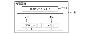
- FIG. 2 is a diagram illustrating an example of a hardware configuration of a process control computer that implements a plate thickness control device.
- FIG. 13 is a diagram for explaining eccentricity of a reel.
- the rolling mill 1 has one rolling stand 11.
- the rolling stand 11 has a pair of upper and lower work rolls 111, a pair of upper and lower backup rolls 112, and an electric motor 113 for rotating the rolls.
- the backup rolls 112 are provided with a reduction device 114, and the reduction opening of the reduction device 114, and thus the roll gap between the upper and lower work rolls 111, is controlled by a reduction opening control device 115.
- the torque control devices 22 and 32 determine the torque (or current) of the electric motors 21 and 31 based on the correction amount of tension control that controls the tension of the rolled material M at the entrance and exit sides of the rolling mill 1 measured by the tension meters 6 and 7 to a given tension target value.
- the cold rolling plant RP is operated by a control system using a computer.
- the computer includes a host computer 40 and a process control computer 41, which are connected to each other via a network.
- An interface screen 42 which is an operation screen for an operator, is connected to the process control computer 41 via the network. The operator can perform operations such as inputting control conditions on the interface screen 42.
- the process control computer 41 executes setting calculation and control of control objects in a series of rolling processes.
- the process control computer 41 also has a function of controlling the reduction aperture of the reduction device 114.
- a target thickness value (product thickness) h REF [mm] of the rolled material M is input to the process control computer 41 from the host computer 40.
- the process control computer 41 appropriately controls each piece of equipment based on the target thickness value h REF [mm] and control conditions provided from the interface screen 42.
- the process control computer 41 calculates the settings of each piece of equipment that can achieve the target thickness value h REF , and operates the actuators of each piece of equipment based on these settings. While each piece of equipment is in operation, the operation of the actuators is corrected according to values obtained from various measuring instruments.
- the process control computer 41 operates the reduction device 114 of the rolling stand 11 of the rolling mill 1 to adjust the roll gap so that the measured thickness value (actual thickness) h of the rolled material M becomes the target thickness value (i.e., to cancel the thickness deviation).
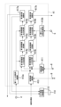
- FIG. 2 is a schematic diagram showing the configuration of a process control computer 41, which is a thickness control device for a rolling mill according to an embodiment.
- FIG. 3 is a diagram for explaining the division numbers assigned to the divided parts obtained by dividing the reels 2 and 3 at equal rotation angles.
- FIG. 4 is a diagram showing a first table Tb1 stored by the thickness deviation input determination unit.
- FIG. 5 is a diagram showing a second table Tb2 stored by the thickness deviation storage unit.
- the process control computer 41 includes a travel distance calculation unit 411, a reel rotation angle calculation unit 412 (412a, 412b), a thickness deviation calculation unit 413, a thickness deviation input determination unit 414 (414a, 414b), a thickness deviation storage unit 415 (415a, 415b), a thickness deviation output determination unit 416 (416a, 416b), and an operation amount calculation unit 417 (417a, 417b).
- the first reel rotation angle calculation unit 412a and the second reel rotation angle calculation unit 412b are not explained individually, but are explained as the reel rotation angle calculation unit 412. The same applies to the thickness deviation input determination unit 414, the thickness deviation storage unit 415, the thickness deviation output determination unit 416, and the operation amount calculation unit 417.
- the travel distance calculation unit 411 calculates the distance ⁇ L traveled by the rolled material M during a calculation period ⁇ t [sec] from the speed v [m/s] of the rolled material M measured by the strip speed meter 8, using the following formula (1).
- the calculation period ⁇ t can be set according to the speed v [m/s] of the rolled material M, and can be set to, for example, 20 msec.
- ⁇ L v ⁇ 1000 ⁇ t...(1)
- the travel distance ⁇ L of the rolled material M may be calculated from the circumferential speed V R [m/s] of the work roll of the rolling mill 1 (hereinafter referred to as "roll circumferential speed") and the forward slip f according to the following formula (2).
- ⁇ L V R ⁇ (1+f) ⁇ ⁇ t...(2)
- the plate thickness deviation calculation unit 413 calculates a plate thickness deviation ⁇ h x [mm] based on the plate thickness measurement value h MEAS [mm] measured by the plate thickness meter 9 using the following formula (3).
- ⁇ h x h MEAS - h REF ...
- h REF is the plate thickness target value [mm].
- the plate thickness deviation ⁇ h x [mm] is transmitted from the plate thickness gauge 9 to the plate thickness deviation calculation unit 413, it may be used as it is.
- the thickness deviation input determination unit 414 determines the timing of inputting the thickness deviation ⁇ h x calculated by the thickness deviation calculation unit 413 to the thickness deviation storage unit 415. As shown in FIG. 3, one rotation of each of the entry reel 2 and the exit reel 3 is divided into N equal rotation angles, and division numbers from 0 to N-1 are assigned in advance. As shown in FIG. 4, the thickness deviation input determination unit 414 has a first table Tb1 that can store N elements corresponding to the division number N (i.e., division number n) of each of the entry reel 2 and the exit reel 3.
- the plate thickness deviation input determination unit 414 adds the movement distance ⁇ L calculated by the movement distance calculation unit 411 to each element in the lower row of the first table Tb1 (see formula (4) below). For example, if the rolled material M moves 50 mm every calculation cycle ⁇ t, 50 mm is added to each element distance L 0 to L N-1 at each calculation timing.
- the control cycle k may be the same as the calculation cycle ⁇ t or may be different from the calculation cycle ⁇ t.
- Ln[k] Ln[k-1]+ ⁇ L[k]...(4)
- the thickness deviation input determination unit 414 clears the distance Ln from the rolling mill 1 corresponding to division number n to zero.
- the thickness deviation storage unit 415 has a structure similar to that of the thickness deviation input determination unit 414. As shown in FIG. 5, the thickness deviation storage unit 415 has a second table Tb2 that can store N elements corresponding to the division number N (i.e., division number n) of each of the entry reel 2 and the exit reel 3.
- the thickness deviation storage unit 415 performs the calculation of the following formula (10), and stores the calculation result in the lower part of the second table Tb2 as a new integrated value of the thickness deviation at the division number n.
- ⁇ h n [k] ⁇ h n [k-1]+ ⁇ h x [k]...(10)
- the forgetting factor ⁇ when the forgetting factor ⁇ is set to 1, the thickness deviation in control cycle k and the thickness deviation stored (already stored) prior to control cycle k (k-1, k-2, ...) are stored with equal weighting.
- the weighting of the thickness deviation stored prior to control cycle k can be reduced. For example, in cases where the correspondence between the division number (rotation angle) and the thickness deviation measurement point shifts over time, the weighting of the thickness deviation measured in the past can be reduced by setting the forgetting factor ⁇ to a value smaller than 1, which advantageously improves the accuracy of thickness control.
- the thickness deviation output determination unit 416 determines the timing for outputting the integrated value of the thickness deviation from the thickness deviation storage unit 415. That is, the thickness deviation output determination unit 416 determines that the output timing of the integrated value of the thickness deviation corresponding to the division number is when the rotation angles of the input reel 2 and output reel 3 calculated by the reel rotation angle calculation unit 412 become the rotation angles corresponding to the division number.
- the thickness deviation output determination unit 416 compensates for the response delay of the screw down device 114 by regarding the response delay of the screw down device 114 as a first-order delay, similarly to the thickness deviation input determination unit 414.
- the output timing for the division number n is determined for the inlet reel 2 using the following formulas (11) and (12), and for the outlet reel 3 using the following formulas (13) and (14), respectively.
- ⁇ ENT and ⁇ DEL are the entry reel rotation angle [rad] and the delivery reel rotation angle [rad] and ⁇ n is the rotation angle [rad] corresponding to division number n.
- T H is the time constant [s] of the screw-down device 114, and ⁇ ENT and ⁇ DEL are the rotation angular velocities [rad/s] of the entry reel 2 and the delivery reel 3.
- ⁇ S is the amount of adjustment of the reduction opening of the reduction device 114 (hereinafter also referred to as the “operation amount”) [mm]
- K is an adjustment coefficient
- M is the mill constant of the rolling mill 1 [kN/mm]
- Q is the plasticity coefficient of the rolled material M [kN/mm]
- ⁇ h n is the integrated value [mm] of the thickness deviation of the division number n.
- the effect of eccentricity of the reels 2, 3 is large when the coil diameter (also called coil diameter) of the rolled material M wound around the reels 2, 3 is small, and gradually decreases as the coil diameter increases. Therefore, as shown in FIG. 6, it is preferable to set the adjustment coefficient K in advance in accordance with changes in the coil diameter, obtain the adjustment coefficient K corresponding to the coil diameter when calculating the roll down opening operation amount ⁇ S, and adjust the operation amount ⁇ S using (multiplying) the obtained adjustment coefficient K. In this way, when the coil diameter is small, the plate thickness control effect by the operation amount ⁇ S can be increased, and when the coil diameter is large, the roll down opening operation amount ⁇ S can be suppressed to prevent it from becoming a disturbance to the plate thickness control.
- the operation amount calculation unit 417 may be configured to set upper and lower limit values, as shown in the following equation (16), for the operation amount (correction amount) ⁇ S of the press-down opening control device 115 calculated by the above equation (15), and to set the operation amount ⁇ S to the upper and lower limit values when this range is exceeded.
- ⁇ S LL is a lower limit value
- ⁇ S UL is an upper limit value.
- the deviation between the tension target value after correction and the tension target value becomes smaller than before the correction, and excessive tension control is not performed, so that it is possible to prevent adverse effects on the thickness at the exit side of the rolling mill 1.
- upper and lower limits may be set for the correction amount of the tension target value, and correction may be performed within that range.
- the relationship between the amount of operation of the roll down opening ⁇ S and the change in tension can be set in advance by changing the roll down opening of the roll down device 114 through an experiment and measuring the change in tension at that time, or by determining the correlation between the amount of change in the roll down opening ( ⁇ S) and the amount of change in tension through a simulation.
- the processing circuit may include at least one processor 41b and at least one memory 41c.
- each function of the process control computer 41 is realized by software, firmware, or a combination of software and firmware.
- the software and firmware are written as programs and stored in the memory 41c.
- the processor 41b realizes the functions of each part of the plate thickness control device 41 by reading and executing the programs stored in the memory 41c.
- the processor 41b is also called a CPU (Central Processing Unit), central processing unit, processing unit, arithmetic unit, microprocessor, microcomputer, or DSP.
- the memory 41c is, for example, a non-volatile or volatile semiconductor memory such as a RAM, ROM, flash memory, EPROM, or EEPROM.
Landscapes
- Engineering & Computer Science (AREA)
- Mechanical Engineering (AREA)
- Control Of Metal Rolling (AREA)
Priority Applications (3)
| Application Number | Priority Date | Filing Date | Title |
|---|---|---|---|
| JP2024556318A JP7772251B2 (ja) | 2023-10-10 | 2023-10-10 | 圧延機の板厚制御装置 |
| CN202380072498.XA CN120129575A (zh) | 2023-10-10 | 2023-10-10 | 轧机的板厚控制装置 |
| PCT/JP2023/036763 WO2025079142A1 (ja) | 2023-10-10 | 2023-10-10 | 圧延機の板厚制御装置 |
Applications Claiming Priority (1)
| Application Number | Priority Date | Filing Date | Title |
|---|---|---|---|
| PCT/JP2023/036763 WO2025079142A1 (ja) | 2023-10-10 | 2023-10-10 | 圧延機の板厚制御装置 |
Publications (1)
| Publication Number | Publication Date |
|---|---|
| WO2025079142A1 true WO2025079142A1 (ja) | 2025-04-17 |
Family
ID=95395387
Family Applications (1)
| Application Number | Title | Priority Date | Filing Date |
|---|---|---|---|
| PCT/JP2023/036763 Pending WO2025079142A1 (ja) | 2023-10-10 | 2023-10-10 | 圧延機の板厚制御装置 |
Country Status (3)
| Country | Link |
|---|---|
| JP (1) | JP7772251B2 (https=) |
| CN (1) | CN120129575A (https=) |
| WO (1) | WO2025079142A1 (https=) |
Citations (3)
| Publication number | Priority date | Publication date | Assignee | Title |
|---|---|---|---|---|
| JPS60257913A (ja) * | 1984-06-04 | 1985-12-19 | Hitachi Ltd | 板厚制御の方法および装置 |
| JP2011011237A (ja) * | 2009-07-02 | 2011-01-20 | Nisshin Steel Co Ltd | 圧延の板厚制御方法 |
| JP2017124428A (ja) * | 2016-01-14 | 2017-07-20 | 株式会社日立製作所 | 圧延機制御装置、圧延機制御方法およびプログラム |
Family Cites Families (1)
| Publication number | Priority date | Publication date | Assignee | Title |
|---|---|---|---|---|
| JPS6146311A (ja) * | 1984-08-10 | 1986-03-06 | Toshiba Corp | 1スタンド多パス圧延機の板厚制御装置 |
-
2023
- 2023-10-10 CN CN202380072498.XA patent/CN120129575A/zh active Pending
- 2023-10-10 JP JP2024556318A patent/JP7772251B2/ja active Active
- 2023-10-10 WO PCT/JP2023/036763 patent/WO2025079142A1/ja active Pending
Patent Citations (3)
| Publication number | Priority date | Publication date | Assignee | Title |
|---|---|---|---|---|
| JPS60257913A (ja) * | 1984-06-04 | 1985-12-19 | Hitachi Ltd | 板厚制御の方法および装置 |
| JP2011011237A (ja) * | 2009-07-02 | 2011-01-20 | Nisshin Steel Co Ltd | 圧延の板厚制御方法 |
| JP2017124428A (ja) * | 2016-01-14 | 2017-07-20 | 株式会社日立製作所 | 圧延機制御装置、圧延機制御方法およびプログラム |
Also Published As
| Publication number | Publication date |
|---|---|
| JP7772251B2 (ja) | 2025-11-18 |
| JPWO2025079142A1 (https=) | 2025-04-17 |
| CN120129575A (zh) | 2025-06-10 |
Similar Documents
| Publication | Publication Date | Title |
|---|---|---|
| JP5581964B2 (ja) | リバース圧延機における板厚制御方法 | |
| KR101285952B1 (ko) | 리버스식 압연기의 판두께 제어 장치 | |
| JPS595364B2 (ja) | 張力制御方法 | |
| US6606534B1 (en) | Strip thickness control apparatus for rolling mill | |
| JP7772251B2 (ja) | 圧延機の板厚制御装置 | |
| JP7643639B2 (ja) | 圧延機の板厚制御方法および剛性監視方法 | |
| EP0075960B1 (en) | Control device for a continuous rolling machine | |
| KR100929015B1 (ko) | 압연재 소성계수 보정에 의한 예측압연하중 보정방법 | |
| WO2024142253A1 (ja) | 圧延機の板厚制御装置 | |
| JP2829065B2 (ja) | 圧延帯板の板厚測定方法 | |
| JP2803573B2 (ja) | テーパー鋼板の製造方法 | |
| JPH0413413A (ja) | 熱間連続圧延機における通板時の板厚制御方法 | |
| JP7503525B2 (ja) | 圧延機の板厚制御装置および該方法ならびに圧延システム | |
| JP3355089B2 (ja) | 板厚制御装置および板厚制御方法 | |
| JP5565214B2 (ja) | 圧延機の板厚制御方法 | |
| JP2650575B2 (ja) | 厚板の板幅制御圧延方法 | |
| JPH08300024A (ja) | 熱間圧延における板幅制御方法 | |
| JPS6335327B2 (https=) | ||
| JP2950182B2 (ja) | テーパー鋼板の製造方法 | |
| JPH10166019A (ja) | 圧延ラインにおける圧延材の形状制御方法 | |
| JPH10263658A (ja) | 熱間仕上圧延機における圧延材の平坦度制御方法 | |
| JPS6347522B2 (https=) | ||
| JP3350294B2 (ja) | タンデムミルの制御方法および制御装置 | |
| JPWO2025079142A5 (https=) | ||
| JPH0745051B2 (ja) | 圧延材の板幅制御方法 |
Legal Events
| Date | Code | Title | Description |
|---|---|---|---|
| ENP | Entry into the national phase |
Ref document number: 2024556318 Country of ref document: JP Kind code of ref document: A |
|
| WWE | Wipo information: entry into national phase |
Ref document number: 2024556318 Country of ref document: JP |
|
| WWE | Wipo information: entry into national phase |
Ref document number: 202417076354 Country of ref document: IN |
|
| WWE | Wipo information: entry into national phase |
Ref document number: 202380072498.X Country of ref document: CN |
|
| WWP | Wipo information: published in national office |
Ref document number: 202417076354 Country of ref document: IN |
|
| WWP | Wipo information: published in national office |
Ref document number: 202380072498.X Country of ref document: CN |
|
| 121 | Ep: the epo has been informed by wipo that ep was designated in this application |
Ref document number: 23955394 Country of ref document: EP Kind code of ref document: A1 |