WO2025069237A1 - 換気空調システム - Google Patents
換気空調システム Download PDFInfo
- Publication number
- WO2025069237A1 WO2025069237A1 PCT/JP2023/035096 JP2023035096W WO2025069237A1 WO 2025069237 A1 WO2025069237 A1 WO 2025069237A1 JP 2023035096 W JP2023035096 W JP 2023035096W WO 2025069237 A1 WO2025069237 A1 WO 2025069237A1
- Authority
- WO
- WIPO (PCT)
- Prior art keywords
- heat medium
- air
- temperature
- heat
- flow path
- Prior art date
- Legal status (The legal status is an assumption and is not a legal conclusion. Google has not performed a legal analysis and makes no representation as to the accuracy of the status listed.)
- Pending
Links
Images


Classifications
-
- F—MECHANICAL ENGINEERING; LIGHTING; HEATING; WEAPONS; BLASTING
- F24—HEATING; RANGES; VENTILATING
- F24F—AIR-CONDITIONING; AIR-HUMIDIFICATION; VENTILATION; USE OF AIR CURRENTS FOR SCREENING
- F24F1/00—Room units for air-conditioning, e.g. separate or self-contained units or units receiving primary air from a central station
- F24F1/0007—Indoor units, e.g. fan coil units
- F24F1/0035—Indoor units, e.g. fan coil units characterised by introduction of outside air to the room
- F24F1/0038—Indoor units, e.g. fan coil units characterised by introduction of outside air to the room in combination with simultaneous exhaustion of inside air
Definitions
- This disclosure relates to a ventilation and air conditioning system that includes a ventilation device having a heat exchanger, a heat source machine that heats a heat medium, and a radiator that uses the heat of the heat medium to heat a space.
- a ventilation system has an intake fan that sends air taken in through an outdoor intake port to an indoor outlet, an exhaust fan that sends air taken in through an indoor intake port to an outdoor outlet, and a heat exchanger.
- heat exchanger heat is exchanged between the air flowing from the outdoor intake port to the indoor outlet and the air flowing from the indoor intake port to the outdoor outlet.
- the outdoor temperature drops significantly
- the indoor air taken in through the indoor intake port is cooled by the outdoor air taken in through the outdoor intake port, which can cause the water vapor contained in the indoor air to freeze in the heat exchanger.
- conventional ventilation systems with heat exchangers have a problem in that the ventilation air volume can decrease due to freezing in the heat exchanger.
- Patent Document 1 discloses a ventilation device in which a first set temperature and a second set temperature lower than the first set temperature are set, and when the outside air temperature is equal to or lower than the first set temperature and higher than the second set temperature, the supply air blower operates intermittently, and when the outside air temperature is equal to or lower than the second set temperature, the supply air blower is stopped to perform type 3 ventilation.
- the ventilation device disclosed in Patent Document 1 can prevent a decrease in ventilation air volume due to freezing in the heat exchanger by warming the heat exchanger with air taken in from the indoor intake port when the outside air temperature is equal to or lower than the second set temperature.
- Patent Document 1 depending on the outdoor temperature conditions, the operation of the supply air blower is stopped for a certain period of time, and the amount of air supplied to the room is not secured.
- the shortage of air supply volume in the room is made up through the openings in the building. In this case, outside air at the outdoor temperature flows into the room, so the heating load increases significantly compared to when air supply involving heat exchange is performed.
- the present disclosure has been made in consideration of the above, and aims to provide a ventilation and air conditioning system that can prevent a decrease in ventilation air volume due to freezing in the heat exchanger and can reduce the heating load.
- the ventilation and air conditioning system of the present disclosure comprises a heat source unit that heats a heat medium, a radiator that releases heat from the heat medium in the space to be heated, a ventilation device having a heat exchanger that exchanges heat between air supplied from the outside to the inside of the room and air exhausted from the inside of the room to the outside, supplying air to the room and exhausting air from the room, an outdoor air heater that uses a heat medium to heat air taken in from the outside before it is introduced into the heat exchanger, and a heat medium circulation circuit section that forms a flow path for the heat medium that is transported from the heat source unit to each of the radiator and the outdoor air heater and returned to the heat source unit.
- the ventilation and air conditioning system disclosed herein has the effect of preventing a decrease in ventilation air volume due to freezing in the heat exchanger and reducing the heating load.
- FIG. 1 is a diagram showing an example of the configuration of a control circuit according to a first or second embodiment
- FIG. 1 is a diagram showing an example of the configuration of a dedicated hardware circuit according to the first or second embodiment
- Embodiment 1. 1 is a first diagram showing a configuration example of a ventilating air-conditioning system 100 according to embodiment 1.
- the ventilating air-conditioning system 100 is a system that ventilates and air-conditions a room.
- the ventilating air-conditioning system 100 includes a heat source unit 1, a radiator 2, and a ventilation device 3.
- the heat source unit 1 and the radiator 2 constitute an air conditioning system that circulates a heat medium through the radiator 2 to condition the air inside a room.
- the heat source unit 1 heats the heat medium.
- the heat source unit 1 is a heat pump type heat source unit.
- the heat source unit 1 is not limited to a heat pump type heat source unit, and may be a heat source unit that heats the heat medium by burning a fossil fuel such as kerosene or gas.
- the heat medium is, for example, tap water.
- the heat medium is not limited to tap water, and may be a dedicated liquid whose components have been adjusted to prevent freezing or rust.
- the radiator 2 releases heat from the heat medium in the space to be heated.
- the space to be heated is the interior of the building 4.
- the radiator 2 is a radiant radiator such as a floor heating panel or a panel heater, or a fan coil unit such as a fan convector.
- the radiator 2 has a heat medium circuit section 21 which is a flow path of the heat medium in the radiator 2.
- the heat medium circuit section 21 has two connection ports 21a and 21b. The heat medium flows into the radiator 2 from the connection port 21a or the connection port 21b. When the heat medium flows into the radiator 2 from the connection port 21a, the heat medium passes through the heat medium circuit section 21 and flows out of the radiator 2 from the connection port 21b. When the heat medium flows into the radiator 2 from the connection port 21b, the heat medium passes through the heat medium circuit section 21 and flows out of the radiator 2 from the connection port 21a.
- the heat source unit 1 includes a hot water generator 11 and a heat pump unit 12.
- the hot water generator 11 generates hot water, which is a heated heat medium.
- the hot water generator 11 includes a heat exchanger 111 in which heat exchange between the heat medium and the refrigerant is performed, a conveying pump 112 that conveys the heat medium, a heat medium tank 113 in which the heat medium is stored, and a heat medium circuit section 114, which is a flow path of the heat medium in the heat source unit 1.
- the heat medium circuit section 114 has two connection ports 114a and 114b.
- the connection port 114a is the inlet of the heat medium circuit section 114.
- the connection port 114b is the outlet of the heat medium circuit section 114.
- the heat medium flows into the heat source unit 1 from the connection port 114a.
- the heat medium that flows into the heat source unit 1 circulates through the hot water generator 11 by passing through the heat medium circuit section 114, and then reaches the connection port 114b.
- the heat pump unit 12 circulates the refrigerant in the refrigerant circulation circuit section 121.
- the heat medium is heated by the transfer of heat from the refrigerant flowing in the refrigerant circulation circuit section 121 to the heat medium flowing in the heat medium circuit section 114.
- the hot water generator 11 heats the heat medium by utilizing the heat taken in by the refrigerant in the heat pump unit 12.
- the heat medium that flows into the heat source unit 1 from the connection port 114a is collected in the heat medium tank 113.
- the heat medium that leaves the heat medium tank 113 passes through the conveying pump 112 and is then heated in the heat exchanger 111.
- the heat medium that has been heated in the heat exchanger 111 flows out of the heat source unit 1 from the connection port 114b.
- the ventilation device 3 is installed in the attic of the building 4.
- the roof of the building 4 is provided with an outdoor intake port 41 for taking in air outside the building 4, and an outdoor outlet port 42 for discharging air outside the building 4.
- the ceiling of the room is provided with an indoor outlet port 43 for supplying air into the room, and an indoor intake port 44 for taking in air from inside the room.
- An outdoor air duct 45, an exhaust duct 46, an air supply duct 47, and a return air duct 48 are installed in the attic.
- the ventilation device 3 is not limited to being installed in the attic.
- the ventilation device 3 may be installed in any space within the building 4, such as under the floor, in the attic, in a machine room, or in a living space.
- One end of the outdoor air duct 45 is connected to the outdoor intake port 41.
- the other end of the outdoor air duct 45 is connected to the outdoor air duct 32 in the ventilation device 3.
- One end of the exhaust duct 46 is connected to the outdoor outlet 42.
- the other end of the exhaust duct 46 is connected to the exhaust duct 33 in the ventilation device 3.
- One end of the supply air duct 47 is connected to the indoor outlet 43.
- the other end of the supply air duct 47 is connected to the supply air duct 34 in the ventilation device 3.
- One end of the return air duct 48 is connected to the indoor intake port 44.
- the other end of the return air duct 48 is connected to the return air duct 35 in the ventilation device 3.
- the white arrow marked "OA” in Figure 1 shows air outside the building 4 being sucked into the outdoor air inlet 41.
- the white arrow marked “EA” in Figure 1 shows air being blown out of the building 4 from the outdoor air outlet 42.
- the white arrow marked "SA” in Figure 1 shows air being blown out into the room from the indoor air outlet 43.
- the white arrow marked “RA” in Figure 1 shows air inside the room being sucked into the indoor air inlet 44.
- the outside air duct 32, the exhaust air duct 33, the supply air duct 34, and the return air duct 35 are provided inside the housing 30 of the ventilation device 3.
- the heat exchanger 31 is housed inside the housing 30. Inside the housing 30, there are arranged an intake air blower that sends air taken in from outside into the room, and an exhaust air blower that sends air taken in from inside the room to the outside.
- the intake air blower and the exhaust air blower are not shown in Figure 1.
- the intake air blower generates an intake air flow that passes through the outdoor intake port 41 and the outdoor air duct 45 and enters the housing 30.
- the intake air flow passes through the outdoor air duct 32, the heat exchanger 31, and the intake air duct 34 in that order within the housing 30.
- the intake air flow that passes through the housing 30 passes through the intake air duct 47 and the indoor air outlet 43 and is blown out into the room.
- the exhaust air blower generates an exhaust air flow that passes through the indoor intake port 44 and the return air duct 48 and enters the housing 30.
- the exhaust air flow passes through the return air duct 35, the heat exchanger 31, and the exhaust air duct 33 in that order within the housing 30.
- the exhaust air flow that passes through the housing 30 passes through the exhaust duct 46 and the outdoor air outlet 42 and is blown out to the outside.
- each of the intake air blower and the exhaust air blower may be disposed outside the housing 30.
- Two or more intake air blowers may be disposed in the ventilation device 3, and two or more exhaust air blowers may be disposed.
- the heat exchanger 31 has a primary air passage through which the exhaust air flows and a secondary air passage through which the supply air flows.
- the primary air passage and the secondary air passage are perpendicular to each other.
- the primary air passage and the secondary air passage are formed in a laminate composed of alternately bonding sheet materials and spacing materials.
- the sheet material is, for example, flat paperboard that has been processed to be flat.
- the spacing material is, for example, corrugated paperboard. Corrugated paperboard is paper with a corrugated uneven surface.
- total heat exchange between the exhaust air flow and the supply air flow takes place via the flat paperboard. Note that the primary air passage and the secondary air passage are not shown in FIG. 1.
- the heat exchanger 31 is an orthogonal type heat exchanger in which the supply air flow and the exhaust air flow are perpendicular to each other, but this is not limited to this.
- the heat exchanger 31 may also be a counterflow type heat exchanger in which the supply air flow and the exhaust air flow are 180 degrees apart.
- the shape of the spacing member may be sawtooth, sinusoidal, rectangular, or any of these shapes that have been modified.
- the spacing member may also be a combination of multiple plate pieces.
- the outdoor air heater 36 uses a heat medium to heat the air taken in from outside before it is introduced into the heat exchanger 31.
- the outdoor air heater 36 is provided with a heat medium circuit section through which the heat medium passes.
- the heat medium circuit section in the outdoor air heater 36 has two connection ports 36a and 36b.
- the heat medium flows into the outdoor air heater 36 from the connection port 36a or the connection port 36b.
- the heat medium passes through the heat medium circuit section and flows out of the outdoor air heater 36 from the connection port 36b.
- the heat medium flows into the outdoor air heater 36 from the connection port 36b, the heat medium passes through the heat medium circuit section and flows out of the outdoor air heater 36 from the connection port 36a.
- the heat medium circuit section in the outdoor air heater 36 is not shown except for the connection ports 36a and 36b.
- the outdoor air heater 36 shown in FIG. 1 is disposed in the outdoor air duct 32.
- the outdoor air duct 32 is an air duct through which air that flows into the ventilation device 3 from the outdoors passes until it reaches the heat exchanger 31.
- the heat medium is transported from the heat source unit 1 to the outdoor air heater 36 in the heat medium circulation circuit section 22, the heat of the heat medium passing through the heat medium circuit section in the outdoor air heater 36 is transferred to the air passing through the outdoor air duct 32.
- the air before being introduced into the heat exchanger 31 is heated in the outdoor air duct 32.
- the outdoor air heater 36 is, for example, a plate fin type heater in which multiple metal plates are connected to a metal tube that constitutes the heat medium circuit section.
- the air in the outdoor air duct 32 is heated by the heat of the heat medium passing through the metal tube being transmitted from the metal tube and metal plate to the air surrounding the metal tube and metal plate.
- the outdoor air heater 36 is not limited to a plate fin type heater, and may be a heater made of a single metal tube.
- the outdoor air heater 36 may be one that heats the air in the outdoor air duct 32 by passing a heat medium through a metal tube that is in contact with the inner wall of the outdoor air duct 32.
- the ventilation and air conditioning system 100 switches the heat medium circulation circuit section 22 between a first state in which the transport of the heat medium to the outdoor air heater 36 is stopped, and a second state in which the heat medium is transported to the outdoor air heater 36.
- the heat medium circulation circuit section 22 has a first flow path 25 and a second flow path 26.
- the first flow path 25 is a flow path through which the heat medium that has passed through the radiator 2 returns to the heat source unit 1 in the first state.
- the second flow path 26 is a flow path that transports the heat medium to the outdoor air heater 36 in the second state.
- the ventilation and air conditioning system 100 includes a flow path switching valve 23, which is a first valve, and a directional control valve 24, which is a second valve.
- the flow path switching valve 23 switches the flow path of the heat medium between a first flow path 25 and a second flow path 26.
- the flow path switching valve 23 functions as a switching unit that switches the heat medium circulation circuit unit 22 between a first state in which the transport of the heat medium to the outdoor air heater 36 is stopped, and a second state in which the heat medium is transported to the outdoor air heater 36.
- the flow path switching valve 23 has three connection ports 23a, 23b, and 23c.
- the directional control valve 24 switches the direction in which the heat medium flows in the heat medium circulation circuit section 22. In the second state, the directional control valve 24 switches the direction in which the heat medium flows between the direction in which the heat medium that flows from the heat source unit 1 to the radiator 2 passes through the outdoor air heater 36 and returns to the heat source unit 1, and the direction in which the heat medium that flows from the heat source unit 1 to the outdoor air heater 36 passes through the radiator 2 and returns to the heat source unit 1.
- the directional control valve 24 has four connection ports 24a, 24b, 24c, and 24d.
- connection port 23a of the flow path switching valve 23 is connected to the connection port 21b of the radiator 2 via a pipe.
- the connection port 23b of the flow path switching valve 23 is connected to the connection port 24c of the direction switching valve 24 via a pipe.
- the connection port 23c of the flow path switching valve 23 is connected to the connection port 36a of the outdoor air heater 36 via a pipe.
- the connection port 24a of the direction switching valve 24 is connected to the connection port 114b of the heat source unit 1 via a pipe.
- connection port 24b of the direction switching valve 24 is connected to the connection port 21a of the radiator 2 via a pipe.
- the connection port 24d of the direction switching valve 24 is connected to the connection port 114a of the heat source unit 1 via a pipe.
- connection port 36b of the outdoor air heater 36 is connected to the connection point 27 via a pipe.
- the connection point 27 is provided in the pipe between the connection port 23b of the flow path switching valve 23 and the connection port 24c of the direction switching valve 24.
- the first flow path 25 is a flow path between the connection port 23b of the flow path switching valve 23 and the connection point 27.
- the second flow path 26 is a flow path between the connection port 23c of the flow path switching valve 23 and the connection port 36a of the outdoor air heater 36, and a flow path between the connection port 36b of the outdoor air heater 36 and the connection point 27.
- the ventilation and air conditioning system 100 includes a control device 5 that controls the ventilation and air conditioning system 100.
- the control device 5 is connected to each of the heat source unit 1, the ventilation device 3, the flow path switching valve 23, and the directional control valve 24 by communication lines.
- the control device 5 controls each of the heat source unit 1, the ventilation device 3, the flow path switching valve 23, and the directional control valve 24 by sending control signals via the communication lines.
- the dashed lines between the control device 5 and each of the heat source unit 1, the ventilation device 3, the flow path switching valve 23, and the directional control valve 24 represent communication lines.
- the control device 5 instructs the flow path switching valve 23 to switch the flow path by sending a control signal to the flow path switching valve 23.
- the flow path switching valve 23 switches the flow path in accordance with the control signal sent from the control device 5.
- the control device 5 instructs the direction switching valve 24 to switch the flow path by sending a control signal to the direction switching valve 24.
- the direction switching valve 24 switches the flow path in accordance with the control signal sent from the control device 5.
- the direction switching valve 24 switches the flow path, thereby switching the direction in which the heat medium flows in the heat medium circulation circuit section 22.
- the ventilation and air conditioning system 100 is equipped with an outdoor air temperature detector that detects the temperature of the air outside.
- the ventilation and air conditioning system 100 shown in FIG. 1 is equipped with two outdoor air temperature detectors 51, 52.
- the outdoor air temperature detector 51 is arranged in the outdoor air duct 32 inside the ventilation device 3.
- the outdoor air temperature detector 51 detects the temperature of the air outside by detecting the temperature of the air passing through the outdoor air duct 32.
- the outdoor air temperature detector 52 is arranged in the heat pump unit 12.
- the outdoor air temperature detector 52 detects the temperature of the air outside in the heat pump unit 12.
- the outdoor air heater 36 heats the air in the outdoor air duct 32 at a position downwind from the position where the outdoor air temperature detector 51 detects the air temperature.
- the outdoor air temperature detector 51 detects the air temperature at a position upwind from the position where the air is heated by the outdoor air heater 36, so it is possible to detect the temperature of the air before it is heated. This allows the ventilation and air conditioning system 100 to accurately detect the temperature of the outdoor air using the outdoor air temperature detector 51.
- the control device 5 is connected to each of the two outside air temperature detectors 51, 52 via a communication line.
- the dashed lines between each of the outside air temperature detectors 51, 52 and the control device 5 represent the communication lines.
- Each of the two outside air temperature detectors 51, 52 outputs a signal indicating the detected temperature to the control device 5 via the communication line. In this way, the control device 5 obtains information on the temperature detected by each of the two outside air temperature detectors 51, 52.
- the control device 5 controls each of the flow path switching valve 23 and the directional control valve 24 based on the temperatures detected by the outside air temperature detectors 51, 52.
- the ventilation and air conditioning system 100 may have only one of the two outdoor temperature detectors 51, 52.
- the ventilation and air conditioning system 100 may use one of the two outdoor temperature detectors 51, 52 as the main outdoor temperature detector and the other as an auxiliary outdoor temperature detector.
- the control device 5 may obtain temperature information based on a signal from the main outdoor temperature detector, and obtain temperature information based on a signal from the auxiliary outdoor temperature detector when a signal cannot be obtained from the main outdoor temperature detector.
- the ventilation and air conditioning system 100 may obtain information indicating the outdoor temperature from a temperature detection means other than the outdoor temperature detectors 51, 52. In the following description, the control device 5 obtains temperature information based on a signal from the outdoor temperature detector 51, which is the main outdoor temperature detector.
- the control device 5 compares the temperature detected by the outside air temperature detector 51 with a first temperature, which is a preset temperature. When the temperature detected by the outside air temperature detector 51 is higher than the first temperature, the control device 5 instructs the flow path switching valve 23 to open the first flow path 25 and close the second flow path 26. When the temperature detected by the outside air temperature detector 51 is higher than the first temperature, the flow path switching valve 23 opens the first flow path 25 and closes the second flow path 26. In other words, when the temperature detected by the outside air temperature detector 51 is higher than the first temperature, the flow path switching valve 23 sets the heat medium circulation circuit section 22 to a first state in which the transport of the heat medium to the outside air heater 36 is stopped.
- the flow path switching valve 23 opens the first flow path 25 by opening the connection ports 23a and 23b, and closes the second flow path 26 by closing the connection port 23c.
- the control device 5 instructs the directional control valve 24 to pass the heat medium between the connection ports 24a and 24b and between the connection ports 24c and 24d.
- the directional control valve 24 passes the heat medium between the connection ports 24a and 24b and passes the heat medium between the connection ports 24c and 24d.
- the directional control valve 24 changes the flow direction of the heat medium in the heat medium circulation circuit section 22 so that the heat medium that has flowed from the heat source unit 1 to the radiator 2 returns to the heat source unit 1 through the connection point 27.
- FIG. 1 shows the ventilation and air conditioning system 100 when the heat medium circulation circuit section 22 is in the first state.
- the straight arrows and broken line arrows shown in FIG. 1 indicate the direction in which the heat medium flows in the heat medium circulation circuit section 22.
- the heat medium flowing out from the connection port 114b of the heat source unit 1 passes through the connection ports 24a and 24b of the directional control valve 24, and flows into the radiator 2 from the connection port 21a of the radiator 2.
- the heat medium that flows through the heat medium circuit section 21 in the radiator 2 flows out from the connection port 21b of the radiator 2, then passes through the connection ports 23a and 23b of the flow path switching valve 23, and reaches the connection port 24c of the directional control valve 24 via the connection point 27. That is, the heat medium passes through the first flow path 25 and reaches the connection port 24c of the directional control valve 24.
- the heat medium passes through the connection ports 24c and 24d of the directional control valve 24, and reaches the connection port 114a of the heat source unit 1.
- the heat medium that flows into the heat source unit 1 from the connection port 114a of the heat source unit 1 is heated inside the heat source unit 1 and flows out of the heat source unit 1 again from the connection port 114b of the heat source unit 1.
- the dashed line in flow path switching valve 23 indicates that the heat medium passes between connection port 23a and connection port 23b in flow path switching valve 23.
- one of the two dashed lines in directional control valve 24 indicates that the heat medium passes between connection port 24a and connection port 24b in directional control valve 24, and the other of the two dashed lines in directional control valve 24 indicates that the heat medium passes between connection port 24c and connection port 24d in directional control valve 24.
- the control device 5 instructs the flow path switching valve 23 to close the first flow path 25 and open the second flow path 26.
- the flow path switching valve 23 closes the first flow path 25 and opens the second flow path 26.
- the flow path switching valve 23 sets the heat medium circulation circuit section 22 to a second state in which the heat medium is transported to the outside air heater 36.
- the control device 5 compares the temperature detected by the outside air temperature detector 51 with a second temperature.
- the second temperature is a temperature lower than the first temperature and is a preset temperature.
- the control device 5 instructs the directional control valve 24 to pass the heat medium between the connection port 24a and the connection port 24b and to pass the heat medium between the connection port 24c and the connection port 24d.
- the directional control valve 24 passes the heat medium between the connection port 24a and the connection port 24b and passes the heat medium between the connection port 24c and the connection port 24d.
- the directional control valve 24 changes the flow direction of the heat medium in the heat medium circulation circuit section 22 so that the heat medium that flows from the heat source unit 1 to the radiator 2 passes through the outdoor air heater 36 and returns to the heat source unit 1.
- the control device 5 instructs the directional control valve 24 to pass the heat medium between the connection port 24a and the connection port 24c and between the connection port 24b and the connection port 24d.
- the directional control valve 24 passes the heat medium between the connection port 24a and the connection port 24c and passes the heat medium between the connection port 24b and the connection port 24d.
- the directional control valve 24 changes the flow direction of the heat medium in the heat medium circulation circuit section 22 so that the heat medium that has flowed from the heat source unit 1 to the outside air heater 36 passes through the radiator 2 and returns to the heat source unit 1.
- FIG. 2 is a second diagram showing an example configuration of the ventilation and air conditioning system 100 according to the first embodiment.
- FIG. 2 shows the ventilation and air conditioning system 100 when the heat medium circulation circuit section 22 is in the second state and the temperature detected by the outside air temperature detector 51 is higher than the second temperature. That is, FIG. 2 shows the ventilation and air conditioning system 100 when the temperature detected by the outside air temperature detector 51 is equal to or lower than the first temperature and higher than the second temperature.
- the straight arrows and broken line arrows shown in FIG. 2 indicate the direction in which the heat medium flows in the heat medium circulation circuit section 22.
- the flow path of the heat medium from the connection port 114b of the heat source unit 1 to the connection port 23a of the flow path switching valve 23 is the same as that shown in FIG. 1.
- the heat medium that reaches the connection port 23a of the flow path switching valve 23 passes through the connection port 23c and heads from the connection port 23c to the outdoor air heater 36.
- the heat medium flows into the outdoor air heater 36 from the connection port 36a of the outdoor air heater 36.
- the heat medium that flows through the heat medium circuit section in the outdoor air heater 36 flows out from the connection port 36b of the outdoor air heater 36, and then reaches the connection port 24c of the directional control valve 24 through the connection point 27.
- the heat medium passes through the second flow path 26 and reaches the connection port 24c of the directional control valve 24.
- the heat medium passes through connection ports 24c and 24d in the directional control valve 24 and reaches connection port 114a of the heat source unit 1.
- the heat medium that flows into the heat source unit 1 from connection port 114a of the heat source unit 1 is heated in the heat source unit 1 and flows out of the heat source unit 1 again from connection port 114b of the heat source unit 1.
- the dashed line in flow path switching valve 23 indicates that the heat medium passes between connection port 23a and connection port 23c in flow path switching valve 23.
- one of the two dashed lines in directional control valve 24 indicates that the heat medium passes between connection port 24a and connection port 24b in directional control valve 24, and the other of the two dashed lines in directional control valve 24 indicates that the heat medium passes between connection port 24c and connection port 24d in directional control valve 24.
- the flow path switching valve 23 opens the second flow path 26 by opening the connection ports 23a and 23c, and closes the first flow path 25 by closing the connection port 23b.
- the directional control valve 24 passes the heat medium between the connection ports 24a and 24b and between the connection ports 24c and 24d, thereby changing the flow direction of the heat medium from the heat source unit 1 to the radiator 2 to return to the heat source unit 1 through the outdoor air heater 36.
- FIG. 3 is a third diagram showing an example configuration of the ventilation and air conditioning system 100 according to the first embodiment.
- FIG. 3 shows the ventilation and air conditioning system 100 when the heat medium circulation circuit section 22 is in the second state and the temperature detected by the outside air temperature detector 51 is equal to or lower than the second temperature. That is, FIG. 3 shows the ventilation and air conditioning system 100 when the temperature detected by the outside air temperature detector 51 is equal to or lower than the first temperature and equal to or lower than the second temperature.
- the straight arrows and broken line arrows shown in FIG. 3 indicate the direction in which the heat medium flows in the heat medium circulation circuit section 22.
- the heat medium circulation circuit section 22 When the heat medium circulation circuit section 22 is in the second state and the temperature detected by the outdoor air temperature detector 51 is equal to or lower than the second temperature, the heat medium flowing out from the connection port 114b of the heat source unit 1 passes through the connection ports 24a and 24c in the directional control valve 24, and heads toward the outdoor air heater 36 via the connection point 27. The heat medium flows into the outdoor air heater 36 from the connection port 36b of the outdoor air heater 36. The heat medium that has flowed through the heat medium circuit section in the outdoor air heater 36 flows out from the connection port 36a of the outdoor air heater 36, and then reaches the connection port 23c of the flow path switching valve 23.
- the heat medium that has reached the connection port 23c of the flow path switching valve 23 passes through the connection port 23a and flows into the radiator 2 from the connection port 21b of the radiator 2.
- the heat medium that flows through the heat medium circuit section 21 in the radiator 2 flows out from the connection port 21a of the radiator 2, then passes through the connection ports 24b and 24d in the directional control valve 24 and reaches the connection port 114a of the heat source unit 1.
- the heat medium that flows into the heat source unit 1 from the connection port 114a of the heat source unit 1 is heated in the heat source unit 1 and flows out again from the connection port 114b of the heat source unit 1 to the outside of the heat source unit 1.
- the dashed line in flow path switching valve 23 indicates that the heat medium passes between connection port 23a and connection port 23c in flow path switching valve 23.
- one of the two dashed lines in directional control valve 24 indicates that the heat medium passes between connection port 24a and connection port 24c in directional control valve 24, and the other of the two dashed lines in directional control valve 24 indicates that the heat medium passes between connection port 24b and connection port 24d in directional control valve 24.
- the flow path switching valve 23 opens the second flow path 26 by opening the connection ports 23a and 23c, and closes the first flow path 25 by closing the connection port 23b.
- the directional control valve 24 passes the heat medium between the connection ports 24a and 24c and between the connection ports 24b and 24d, so that the heat medium flows in a direction in which the heat medium that has flowed from the heat source unit 1 to the outdoor air heater 36 passes through the radiator 2 and returns to the heat source unit 1.
- the flow direction of the heat medium in the heat medium circulation circuit section 22 is opposite to that shown in FIG. 2.
- the flow path switching valve 23 puts the heat medium circulation circuit section 22 into the first state when the temperature detected by the outside air temperature detector 51 is higher than the first temperature, and puts the heat medium circulation circuit section 22 into the second state when the temperature detected by the outside air temperature detector 51 is equal to or lower than the first temperature. In this way, the flow path switching valve 23 switches the heat medium circulation circuit section 22 between the first state and the second state based on the detection result by the outside air temperature detector 51. This allows the ventilation and air conditioning system 100 to switch between heating the air taken into the heat exchanger 31 from outside and stopping the heating of the air taken into the heat exchanger 31 from outside depending on whether the outside air temperature is high or low.
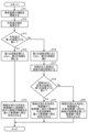
- FIG. 4 is a flowchart showing the procedure of operation of the ventilation and air conditioning system 100 according to the first embodiment.
- the program for implementing the procedure shown in FIG. 4 is stored in the control device 5.
- step S1 the ventilation and air conditioning system 100 starts the operation of the ventilation device 3.
- the control device 5 starts the operation of the ventilation device 3 by sending a control signal to the ventilation device 3.
- the heat source unit 1 does not need to be in a powered state at the time of step S1.
- step S2 the control device 5 acquires the value of the outside air temperature.
- the outside air temperature detector 51 detects the outside air temperature, which is the temperature of the air outside the room, when the ventilation device 3 is in an energized state.
- the outside air temperature detector 51 sends a signal indicating the detected outside air temperature to the control device 5.
- the control device 5 acquires the value of the outside air temperature from the outside air temperature detector 51 by receiving the signal sent from the outside air temperature detector 51.
- the control device 5 acquires the value of the outside air temperature from the outside air temperature detector 51, the heat source unit 1 does not need to be in an energized state at the time of step S2.
- the control device 5 acquires the value of the outside air temperature from the outside air temperature detector 52, the heat source unit 1 is in an energized state at the time of step S2.
- the outside air temperature detector 52 detects the outside air temperature when the heat source unit 1 is in an energized state.
- step S3 the control device 5 determines whether the outside air temperature is higher than the first temperature. If the control device 5 determines that the outside air temperature is higher than the first temperature (step S3, Yes), it instructs the flow path switching valve 23 to open the first flow path 25 and close the second flow path 26. In step S4, the flow path switching valve 23 opens the first flow path 25 and closes the second flow path 26 in accordance with the instruction from the control device 5. In this way, when the temperature detected by the outside air temperature detector 51 is higher than the first temperature, the heat medium circulation circuit section 22 enters a first state in which the transport of heat medium to the outside air heater 36 is stopped.
- step S4 the control device 5 instructs the directional control valve 24 to pass the heat medium between the connection port 24a and the connection port 24b and between the connection port 24c and the connection port 24d.
- the directional control valve 24, in accordance with the instruction from the control device 5, passes the heat medium between the connection port 24a and the connection port 24b and passes the heat medium between the connection port 24c and the connection port 24d.
- the directional control valve 24 changes the flow direction of the heat medium in the heat medium circulation circuit section 22 so that the heat medium that has flowed from the heat source unit 1 to the radiator 2 returns to the heat source unit 1 through the connection point 27.
- the heat medium flows through the heat medium circulation circuit section 22 and is transported to the radiator 2 as shown in FIG. 1.
- step S3 No If the control device 5 determines that the outside air temperature is not higher than the first temperature (step S3, No), that is, if the control device 5 determines that the outside air temperature is equal to or lower than the first temperature, the control device 5 instructs the flow path switching valve 23 to close the first flow path 25 and open the second flow path 26. In step S6, the flow path switching valve 23 closes the first flow path 25 and opens the second flow path 26 in accordance with the instruction from the control device 5.
- step S7 the control device 5 determines whether the outside air temperature is higher than the second temperature. If it is determined that the outside air temperature is higher than the second temperature (step S7, Yes), the control device 5 instructs the directional control valve 24 to pass the heat medium between the connection port 24a and the connection port 24b and between the connection port 24c and the connection port 24d. In accordance with the instruction from the control device 5, the directional control valve 24 passes the heat medium between the connection port 24a and the connection port 24b and passes the heat medium between the connection port 24c and the connection port 24d.
- step S8 the directional control valve 24 changes the flow direction of the heat medium in the heat medium circulation circuit section 22 so that the heat medium that has flowed from the heat source unit 1 to the radiator 2 passes through the outside air heater 36 and returns to the heat source unit 1.
- the heat medium flows through the heat medium circulation circuit section 22 as shown in FIG. 2 and is transported to the radiator 2 and the outdoor air heater 36.
- step S7, No When the control device 5 determines that the outside air temperature is not higher than the second temperature (step S7, No), that is, when the control device 5 determines that the outside air temperature is equal to or lower than the second temperature, the control device 5 instructs the directional control valve 24 to pass the heat medium between the connection port 24a and the connection port 24c and between the connection port 24b and the connection port 24d.
- the directional control valve 24, in accordance with the instruction from the control device 5, passes the heat medium between the connection port 24a and the connection port 24c and passes the heat medium between the connection port 24b and the connection port 24d.
- step S9 the directional control valve 24 changes the flow direction of the heat medium in the heat medium circulation circuit section 22 so that the heat medium that has flowed from the heat source unit 1 to the outdoor air heater 36 passes through the radiator 2 and returns to the heat source unit 1.
- the heat medium flows through the heat medium circulation circuit section 22 as shown in FIG. 3 and is transported to the outdoor air heater 36 and the radiator 2.
- the ventilation and air conditioning system 100 ends the operation according to the procedure shown in FIG. 4. While the operation of the ventilation device 3 continues, the ventilation and air conditioning system 100 periodically obtains the value of the outside air temperature using the control device 5, and repeats the operation from step S2 to step S5, step S8, or step S9.
- the flow path switching valve 23 sets the heat medium circulation circuit section 22 to the second state when the outside air temperature matches the first temperature, but this is not limited to the above.
- the flow path switching valve 23 may set the heat medium circulation circuit section 22 to the first state when the outside air temperature matches the first temperature.
- the flow path switching valve 23 may at least set the heat medium circulation circuit section 22 to the first state when the outside air temperature is higher than the first temperature, and set the heat medium circulation circuit section 22 to the second state when the outside air temperature is lower than the first temperature.
- the directional control valve 24 changes the flow direction of the heat medium from the heat source unit 1 to the outdoor air heater 36 to return to the heat source unit 1 through the radiator 2 when the outdoor air temperature is equal to the second temperature, but this is not limited to the above.
- the directional control valve 24 may change the flow direction of the heat medium from the heat source unit 1 to the radiator 2 to return to the heat source unit 1 through the outdoor air heater 36 when the outdoor air temperature is equal to the second temperature.
- the directional control valve 24 may at least change the flow direction of the heat medium from the heat source unit 1 to the radiator 2 to return to the heat source unit 1 through the outdoor air heater 36 when the outdoor air temperature is higher than the second temperature, and change the flow direction of the heat medium from the heat source unit 1 to the outdoor air heater 36 to return to the heat source unit 1 through the radiator 2 when the outdoor air temperature is lower than the second temperature.
- the flow path switching valve 23 sets the heat medium circulation circuit section 22 to a first state in which the transport of heat medium to the outdoor air heater 36 is stopped.
- the ventilation and air conditioning system 100 can prevent a decrease in ventilation air volume due to freezing in the heat exchanger 31 even if the transport of heat medium to the outdoor air heater 36 is stopped.
- the ventilation and air conditioning system 100 can reduce the energy consumption of the heat source unit 1 by stopping the transport of heat medium to the outdoor air heater 36.
- the ventilation and air conditioning system 100 reduces freezing in the heat exchanger 31 by transporting the heat medium to the outside air heater 36. By reducing freezing in the heat exchanger 31, the ventilation and air conditioning system 100 can prevent a decrease in ventilation air volume due to freezing in the heat exchanger 31.
- the directional control valve 24 changes the flow direction of the heat medium in the heat medium circulation circuit section 22 so that the heat medium that has flowed from the heat source unit 1 to the radiator 2 passes through the outside air heater 36 and returns to the heat source unit 1.
- the heat medium leaving the heat source unit 1 is transported to the radiator 2 before the outside air heater 36.
- the directional control valve 24 changes the flow direction of the heat medium in the heat medium circulation circuit section 22 so that the heat medium that has flowed from the heat source unit 1 to the outdoor air heater 36 passes through the radiator 2 and returns to the heat source unit 1. In this case, the heat medium leaving the heat source unit 1 is transported to the outdoor air heater 36 before the radiator 2.
- the ventilation and air conditioning system 100 can secure a large amount of thermal energy to be released in the outdoor air duct 32 regardless of the heating load inside the room. This allows the ventilation and air conditioning system 100 to reduce freezing in the heat exchanger 31 when the outdoor air temperature drops significantly. By reducing freezing in the heat exchanger 31, the ventilation and air conditioning system 100 can prevent a decrease in the ventilation air volume due to freezing in the heat exchanger 31.
- the ventilation air-conditioning system 100 includes an outdoor air heater 36 that uses a heat medium to heat the air taken in from the outside before it is introduced into the heat exchanger 31, and a heat medium circulation circuit section 22 that configures a flow path for the heat medium that is transported from the heat source unit 1 to each of the radiator 2 and the outdoor air heater 36 and returned to the heat source unit 1.
- the ventilation air-conditioning system 100 can prevent a decrease in ventilation air volume due to freezing in the heat exchanger 31 by heating the air with the outdoor air heater 36.
- the ventilation air-conditioning system 100 can ensure the volume of air supplied indoors because it continues to supply air by the ventilation device 3 regardless of the outdoor air temperature conditions.
- the ventilation air-conditioning system 100 can reduce the heating load compared to when third-type ventilation is performed because it continues to supply air with heat exchange by the ventilation device 3. As described above, the ventilation air-conditioning system 100 has the effect of preventing a decrease in ventilation air volume due to freezing in the heat exchanger 31 and reducing the heating load.
- Embodiment 2. 5 is a first diagram showing a configuration example of a ventilating air-conditioning system 101 according to embodiment 2.
- the ventilating air-conditioning system 101 is a system that ventilates and air-conditions the room.
- the ventilating air-conditioning system 101 includes a heat source unit 1, a radiator 2, and a ventilation device 3.
- the ventilation device 3 of the ventilation and air conditioning system 101 does not have the outdoor air heater 36 shown in FIG. 1.
- the ventilation and air conditioning system 101 has an outdoor air heater 49 arranged in an outdoor air duct 45.
- the same components as those in the first embodiment above are given the same reference numerals, and the following mainly describes the configuration that differs from the first embodiment.
- the outdoor air heater 49 is provided with a heat medium circuit section through which the heat medium passes.
- the heat medium circuit section in the outdoor air heater 49 has two connection ports 49a, 49b.
- the heat medium flows into the outdoor air heater 49 from the connection port 49a or the connection port 49b.
- the heat medium passes through the heat medium circuit section and flows out of the outdoor air heater 49 from the connection port 49b.
- the heat medium flows into the outdoor air heater 49 from the connection port 49b, the heat medium passes through the heat medium circuit section and flows out of the outdoor air heater 49 from the connection port 49a. Note that in FIG. 5, the heat medium circuit section in the outdoor air heater 49 is not shown except for the connection ports 49a, 49b.
- the outside air heater 49 is, for example, a plate fin type heater in which multiple metal plates are connected to a metal tube that constitutes the heat medium circuit section.
- the air in the outside air duct 45 is heated by the heat of the heat medium passing through the metal tube being transmitted from the metal tube and metal plate to the air surrounding the metal tube and metal plate.
- the outside air heater 49 is not limited to a plate fin type heater, and may be a heater made of a single metal tube.
- the outside air heater 49 may be one that heats the air in the outside air duct 45 by passing a heat medium through a metal tube that is in contact with the inner wall of the outside air duct 45.
- the ventilation device 3 can be made smaller than when the outdoor air heater 49 is installed inside the ventilation device 3.
- the degree of freedom in the shape of the outdoor air heater 49 can be increased.
- the ventilation and air conditioning system 101 switches the heat medium circulation circuit section 22 between a first state in which the transport of the heat medium to the outdoor air heater 49 is stopped, and a second state in which the heat medium is transported to the outdoor air heater 49.
- the first flow path 25 is a flow path through which the heat medium that has passed through the radiator 2 returns to the heat source unit 1 in the first state.
- the second flow path 26 is a flow path that transports the heat medium to the outdoor air heater 49 in the second state.
- the flow path switching valve 23 switches the heat medium circulation circuit section 22 between the first state in which the transport of the heat medium to the outdoor air heater 49 is stopped, and the second state in which the heat medium is transported to the outdoor air heater 49.
- the directional control valve 24 switches the flow direction of the heat medium between a direction in which the heat medium flows from the heat source unit 1 to the radiator 2 and returns to the heat source unit 1 through the outdoor air heater 49, and a direction in which the heat medium flows from the heat source unit 1 to the outdoor air heater 49 and returns to the heat source unit 1 through the radiator 2.
- connection port 23c of the flow path switching valve 23 is connected to the connection port 49a of the outdoor air heater 49 via piping.
- the connection port 49b of the outdoor air heater 49 is connected to the connection point 27 via piping.
- the first flow path 25 is a flow path between the connection port 23b of the flow path switching valve 23 and the connection point 27.
- the second flow path 26 is a flow path between the connection port 23c of the flow path switching valve 23 and the connection port 49a of the outdoor air heater 49, and a flow path between the connection port 49b of the outdoor air heater 49 and the connection point 27.
- the outdoor air temperature detector 51 detects the air temperature at a position downwind from the position where the outdoor air heater 49 heats the air. Therefore, when the heat medium circulation circuit section 22 is in the second state, the outdoor air temperature detector 51 detects the temperature of the air heated by the outdoor air heater 49.
- the control device 5 obtains information on the temperature of the air heated by the outdoor air heater 49 from the outdoor air temperature detector 51.
- the ventilation and air conditioning system 101 detects the temperature of the air outside the room using the outdoor air temperature detector 52 arranged in the heat pump unit 12. The control device 5 obtains information on the outdoor air temperature from the outdoor air temperature detector 52.
- the control device 5 compares the outside air temperature detected by the outside air temperature detector 52 with a first temperature, which is a preset temperature. When the outside air temperature is higher than the first temperature, the control device 5 instructs the flow path switching valve 23 to open the first flow path 25 and close the second flow path 26 by sending a control signal to the flow path switching valve 23. When the outside air temperature is higher than the first temperature, the flow path switching valve 23 opens the first flow path 25 and closes the second flow path 26. In other words, when the temperature detected by the outside air temperature detector 52 is higher than the first temperature, the flow path switching valve 23 sets the heat medium circulation circuit section 22 to a first state in which the transport of the heat medium to the outside air heater 49 is stopped.
- the flow path switching valve 23 opens the first flow path 25 by opening the connection ports 23a and 23b, and closes the second flow path 26 by closing the connection port 23c.
- the control device 5 instructs the directional control valve 24 to pass the heat medium between the connection ports 24a and 24b and between the connection ports 24c and 24d.
- the directional control valve 24 passes the heat medium between the connection ports 24a and 24b and passes the heat medium between the connection ports 24c and 24d.
- the directional control valve 24 changes the flow direction of the heat medium in the heat medium circulation circuit section 22 so that the heat medium that has flowed from the heat source unit 1 to the radiator 2 returns to the heat source unit 1 through the connection point 27.
- FIG. 5 shows the ventilation and air conditioning system 101 when the heat medium circulation circuit unit 22 is in the first state.
- the straight arrows and broken line arrows shown in FIG. 5 indicate the direction in which the heat medium flows in the heat medium circulation circuit unit 22.
- the manner in which the heat medium flows is the same as when the heat medium circulation circuit unit 22 is in the first state in embodiment 1.
- the dashed line in flow path switching valve 23 indicates that the heat medium passes between connection port 23a and connection port 23b in flow path switching valve 23.
- one of the two dashed lines in directional control valve 24 indicates that the heat medium passes between connection port 24a and connection port 24b in directional control valve 24, and the other of the two dashed lines in directional control valve 24 indicates that the heat medium passes between connection port 24c and connection port 24d in directional control valve 24.
- the control device 5 instructs the flow path switching valve 23 to close the first flow path 25 and open the second flow path 26.
- the flow path switching valve 23 closes the first flow path 25 and opens the second flow path 26.
- the flow path switching valve 23 sets the heat medium circulation circuit section 22 to a second state in which the heat medium is transported to the outside air heater 49.
- the control device 5 compares the temperature detected by the outside air temperature detector 51 with the first temperature. That is, when the temperature detected by the outside air temperature detector 52 is equal to or lower than the first temperature, the control device 5 compares the temperature of the air heated by the outside air heater 49 with the first temperature. When the temperature of the air heated by the outside air heater 49 is higher than the first temperature, the control device 5 instructs the directional control valve 24 to pass the heat medium between the connection port 24a and the connection port 24b and to pass the heat medium between the connection port 24c and the connection port 24d.
- the directional control valve 24 is in a state in which the heat medium is passed between the connection port 24a and the connection port 24b and the heat medium is passed between the connection port 24c and the connection port 24d.
- the directional control valve 24 changes the flow direction of the heat medium in the heat medium circulation circuit section 22 so that the heat medium that flows from the heat source unit 1 to the radiator 2 passes through the outdoor air heater 49 and returns to the heat source unit 1.
- the control device 5 instructs the directional control valve 24 to pass the heat medium between the connection port 24a and the connection port 24c and between the connection port 24b and the connection port 24d.
- the directional control valve 24 passes the heat medium between the connection port 24a and the connection port 24c and between the connection port 24b and the connection port 24d.
- the directional control valve 24 changes the flow direction of the heat medium in the heat medium circulation circuit section 22 to a direction in which the heat medium that has flowed from the heat source unit 1 to the outdoor air heater 49 passes through the radiator 2 and returns to the heat source unit 1.
- FIG. 6 is a second diagram showing an example configuration of the ventilation and air conditioning system 101 according to the second embodiment.
- FIG. 6 shows the ventilation and air conditioning system 101 when the heat medium circulation circuit section 22 is in the second state and the temperature of the air heated by the outdoor air heater 49 is higher than the first temperature. That is, FIG. 6 shows the ventilation and air conditioning system 101 when the outdoor air temperature is equal to or lower than the first temperature and the temperature of the air heated by the outdoor air heater 49 is higher than the first temperature.
- the straight arrows and broken line arrows shown in FIG. 6 indicate the direction in which the heat medium flows in the heat medium circulation circuit section 22.
- the flow path of the heat medium from the connection port 114b of the heat source unit 1 to the connection port 23a of the flow path switching valve 23 is the same as that shown in FIG. 2.
- the heat medium that reaches the connection port 23a of the flow path switching valve 23 passes through the connection port 23c and heads from the connection port 23c to the outdoor air heater 49.
- the heat medium flows into the outdoor air heater 49 from the connection port 49a of the outdoor air heater 49.
- the heat medium that flows through the heat medium circuit section in the outdoor air heater 49 flows out from the connection port 49b of the outdoor air heater 49, and then reaches the connection port 24c of the directional control valve 24 through the connection point 27. That is, the heat medium passes through the second flow path 26 and reaches the connection port 24c of the directional control valve 24.
- the flow path of the heat medium from the connection port 24c of the directional control valve 24 to the connection port 114a of the heat source unit 1 is the same as that shown in FIG. 2.
- the dashed line in flow path switching valve 23 indicates that the heat medium passes between connection port 23a and connection port 23c in flow path switching valve 23.
- one of the two dashed lines in directional control valve 24 indicates that the heat medium passes between connection port 24a and connection port 24b in directional control valve 24, and the other of the two dashed lines in directional control valve 24 indicates that the heat medium passes between connection port 24c and connection port 24d in directional control valve 24.
- FIG. 7 is a third diagram showing an example configuration of the ventilation and air conditioning system 101 according to the second embodiment.
- FIG. 7 shows the ventilation and air conditioning system 101 when the heat medium circulation circuit section 22 is in the second state and the temperature of the air heated by the outdoor air heater 49 is equal to or lower than the first temperature. That is, FIG. 7 shows the ventilation and air conditioning system 101 when the temperature detected by the outdoor air temperature detector 52 is equal to or lower than the first temperature and the temperature of the air heated by the outdoor air heater 49 is equal to or lower than the first temperature.
- the straight arrows and broken line arrows shown in FIG. 7 indicate the direction in which the heat medium flows in the heat medium circulation circuit section 22.
- the dashed line in flow path switching valve 23 indicates that the heat medium passes between connection port 23a and connection port 23c in flow path switching valve 23.
- one of the two dashed lines in directional control valve 24 indicates that the heat medium passes between connection port 24a and connection port 24c in directional control valve 24, and the other of the two dashed lines in directional control valve 24 indicates that the heat medium passes between connection port 24b and connection port 24d in directional control valve 24.
- the flow path switching valve 23 opens the second flow path 26 by opening the connection ports 23a and 23c, and closes the first flow path 25 by closing the connection port 23b.
- the directional control valve 24 passes the heat medium between the connection ports 24a and 24c and between the connection ports 24b and 24d, so that the heat medium flows in a direction in which the heat medium that has flowed from the heat source unit 1 to the outdoor air heater 49 passes through the radiator 2 and returns to the heat source unit 1.
- the flow direction of the heat medium in the heat medium circulation circuit section 22 is opposite to that shown in FIG. 6.
- step S11 the ventilation and air conditioning system 101 starts the operation of the ventilation device 3. If the heat source unit 1 is not in an energized state at the time of step S11, the ventilation and air conditioning system 101 brings the heat source unit 1 into an energized state.
- step S13 the control device 5 determines whether the outside air temperature is higher than the first temperature. If the control device 5 determines that the outside air temperature is higher than the first temperature (step S13, Yes), the control device 5 instructs the flow path switching valve 23 to open the first flow path 25 and close the second flow path 26 by sending a control signal to the flow path switching valve 23. In step S14, the flow path switching valve 23 opens the first flow path 25 and closes the second flow path 26 in accordance with the instruction from the control device 5. In this way, when the temperature detected by the outside air temperature detector 52 is higher than the first temperature, the heat medium circulation circuit unit 22 enters a first state in which the transport of heat medium to the outside air heater 49 is stopped.
- step S14 the control device 5 sends a control signal to the directional control valve 24 to instruct the directional control valve 24 to pass the heat medium between the connection port 24a and the connection port 24b and between the connection port 24c and the connection port 24d.
- the directional control valve 24 passes the heat medium between the connection port 24a and the connection port 24b and between the connection port 24c and the connection port 24d in accordance with the instruction from the control device 5.
- step S15 the directional control valve 24 changes the flow direction of the heat medium in the heat medium circulation circuit section 22 so that the heat medium that has flowed from the heat source unit 1 to the radiator 2 returns to the heat source unit 1 through the connection point 27.
- the heat medium flows through the heat medium circulation circuit section 22 and is transported to the radiator 2 as shown in FIG. 5.
- step S13, No If the control device 5 determines that the outside air temperature is not higher than the first temperature (step S13, No), that is, if the control device 5 determines that the outside air temperature is equal to or lower than the first temperature, the control device 5 instructs the flow path switching valve 23 to close the first flow path 25 and open the second flow path 26 by sending a control signal to the flow path switching valve 23.
- step S16 the flow path switching valve 23 closes the first flow path 25 and opens the second flow path 26 in accordance with the instruction from the control device 5.
- step S17 the control device 5 acquires the value of the temperature of the heated air.
- the outside air temperature detector 51 detects the temperature of the air heated by the outside air heater 49.
- the outside air temperature detector 51 sends a signal indicating the detected temperature to the control device 5.
- the control device 5 acquires the value of the temperature of the heated air from the outside air temperature detector 51 by receiving the signal sent from the outside air temperature detector 51.
- step S20 the directional control valve 24 changes the flow direction of the heat medium in the heat medium circulation circuit section 22 to a direction in which the heat medium that has flowed from the heat source unit 1 to the outdoor air heater 49 passes through the radiator 2 and returns to the heat source unit 1.
- the heat medium flows through the heat medium circulation circuit section 22 as shown in FIG. 7 and is transported to the outdoor air heater 49 and the radiator 2.
- the flow path switching valve 23 sets the heat medium circulation circuit section 22 to the second state when the outside air temperature matches the first temperature, but this is not limited to the above.
- the flow path switching valve 23 may set the heat medium circulation circuit section 22 to the first state when the outside air temperature matches the first temperature.
- the flow path switching valve 23 may at least set the heat medium circulation circuit section 22 to the first state when the outside air temperature is higher than the first temperature, and set the heat medium circulation circuit section 22 to the second state when the outside air temperature is lower than the first temperature.
- the directional control valve 24 at least directs the flow of the heat medium from the heat source unit 1 to the radiator 2 to return to the heat source unit 1 through the outdoor air heater 49 when the temperature of the heated air is higher than the first temperature, and directs the flow of the heat medium from the heat source unit 1 to the outdoor air heater 49 to return to the heat source unit 1 through the radiator 2 when the temperature of the heated air is lower than the first temperature.
- the ventilation and air conditioning system 101 reduces freezing in the heat exchanger 31 by transporting the heat medium to the outside air heater 49. By reducing freezing in the heat exchanger 31, the ventilation and air conditioning system 101 can prevent a decrease in ventilation air volume due to freezing in the heat exchanger 31.
- the directional control valve 24 changes the flow direction of the heat medium in the heat medium circulation circuit section 22 so that the heat medium that has flowed from the heat source unit 1 to the radiator 2 passes through the outdoor air heater 49 and returns to the heat source unit 1.
- the heat medium leaving the heat source unit 1 is transported to the radiator 2 before the outdoor air heater 49.
- the directional control valve 24 changes the flow direction of the heat medium in the heat medium circulation circuit section 22 so that the heat medium that has flowed from the heat source unit 1 to the outdoor air heater 49 passes through the radiator 2 and returns to the heat source unit 1.
- the heat medium that has left the heat source unit 1 is transported to the outdoor air heater 49 before the radiator 2.
- the ventilation and air conditioning system 101 can secure a large amount of thermal energy to be released in the outdoor air duct 45 regardless of the heating load in the room.
- the ventilation and air conditioning system 101 can reliably heat the air by the outdoor air heater 49 to a temperature that can reduce freezing in the heat exchanger 31.
- the ventilation and air conditioning system 101 can reduce freezing in the heat exchanger 31 when the outdoor air temperature drops significantly.
- the ventilation and air conditioning system 101 can prevent a decrease in the ventilation air volume due to freezing in the heat exchanger 31 by reducing freezing in the heat exchanger 31.
- the ventilation and air conditioning systems 100 and 101 can effectively prevent a decrease in ventilation air volume due to freezing in the heat exchanger 31 when the outside air temperature drops significantly.
- the ventilation and air conditioning systems 100 and 101 are used, for example, for indoor ventilation and indoor air conditioning in cold regions.
Landscapes
- Engineering & Computer Science (AREA)
- Chemical & Material Sciences (AREA)
- Combustion & Propulsion (AREA)
- Mechanical Engineering (AREA)
- General Engineering & Computer Science (AREA)
- Air Conditioning Control Device (AREA)
Priority Applications (2)
| Application Number | Priority Date | Filing Date | Title |
|---|---|---|---|
| JP2025548106A JPWO2025069237A1 (https=) | 2023-09-27 | 2023-09-27 | |
| PCT/JP2023/035096 WO2025069237A1 (ja) | 2023-09-27 | 2023-09-27 | 換気空調システム |
Applications Claiming Priority (1)
| Application Number | Priority Date | Filing Date | Title |
|---|---|---|---|
| PCT/JP2023/035096 WO2025069237A1 (ja) | 2023-09-27 | 2023-09-27 | 換気空調システム |
Publications (1)
| Publication Number | Publication Date |
|---|---|
| WO2025069237A1 true WO2025069237A1 (ja) | 2025-04-03 |
Family
ID=95202392
Family Applications (1)
| Application Number | Title | Priority Date | Filing Date |
|---|---|---|---|
| PCT/JP2023/035096 Pending WO2025069237A1 (ja) | 2023-09-27 | 2023-09-27 | 換気空調システム |
Country Status (2)
| Country | Link |
|---|---|
| JP (1) | JPWO2025069237A1 (https=) |
| WO (1) | WO2025069237A1 (https=) |
Citations (4)
| Publication number | Priority date | Publication date | Assignee | Title |
|---|---|---|---|---|
| JP4656777B2 (ja) | 2001-08-31 | 2011-03-23 | 三菱電機株式会社 | 換気装置 |
| WO2019008694A1 (ja) * | 2017-07-05 | 2019-01-10 | 三菱電機株式会社 | 空気調和機及び空気調和システム |
| JP2021156489A (ja) * | 2020-03-27 | 2021-10-07 | パナソニックIpマネジメント株式会社 | 加湿機能付き熱交換形換気装置 |
| JP2023009560A (ja) * | 2021-07-07 | 2023-01-20 | 三菱電機株式会社 | 熱交換型換気装置 |
-
2023
- 2023-09-27 JP JP2025548106A patent/JPWO2025069237A1/ja active Pending
- 2023-09-27 WO PCT/JP2023/035096 patent/WO2025069237A1/ja active Pending
Patent Citations (4)
| Publication number | Priority date | Publication date | Assignee | Title |
|---|---|---|---|---|
| JP4656777B2 (ja) | 2001-08-31 | 2011-03-23 | 三菱電機株式会社 | 換気装置 |
| WO2019008694A1 (ja) * | 2017-07-05 | 2019-01-10 | 三菱電機株式会社 | 空気調和機及び空気調和システム |
| JP2021156489A (ja) * | 2020-03-27 | 2021-10-07 | パナソニックIpマネジメント株式会社 | 加湿機能付き熱交換形換気装置 |
| JP2023009560A (ja) * | 2021-07-07 | 2023-01-20 | 三菱電機株式会社 | 熱交換型換気装置 |
Also Published As
| Publication number | Publication date |
|---|---|
| JPWO2025069237A1 (https=) | 2025-04-03 |
Similar Documents
| Publication | Publication Date | Title |
|---|---|---|
| CN110799793B (zh) | 空调机以及空调系统 | |
| JP5925004B2 (ja) | 空調換気システム | |
| KR102721113B1 (ko) | 공기조화 시스템 | |
| JP4520370B2 (ja) | 水熱源ヒートポンプ式輻射パネル用空調機 | |
| CN211739391U (zh) | 空调系统 | |
| EP1334852B1 (en) | Air conditioner having engine cooling apparatus | |
| US9080795B2 (en) | Air conditioning system | |
| JP4327296B2 (ja) | 空調システム | |
| US20140248832A1 (en) | Method and Apparatus to Provide Ventilation for a Building | |
| WO2025069237A1 (ja) | 換気空調システム | |
| JP6907653B2 (ja) | 空調システム | |
| KR101562744B1 (ko) | 환기 유니트와 연동되는 공조 시스템 | |
| JP2025054999A (ja) | 換気空調システム | |
| JP4353859B2 (ja) | 空気調和装置 | |
| JP2025055001A (ja) | 換気空調システム | |
| JP2025055000A (ja) | 換気空調システム | |
| KR102438699B1 (ko) | 천장복사패널 적용 하이브리드 바닥공조시스템 및 제어방법 | |
| CN104344550A (zh) | 热泵热水器组 | |
| JP4605725B2 (ja) | 増設凝縮装置及びこれを用いた増設凝縮システム付冷凍サイクル装置 | |
| JP5827717B2 (ja) | ヒートポンプ付ファンコイル式放射空調パネル用空調機 | |
| KR20240082033A (ko) | 히트펌프와 공기 가열 장치를 이용하는 난방 시스템 | |
| KR100952518B1 (ko) | 사계절 냉난방설비의 보조열교환기 | |
| KR20180107494A (ko) | 통합 세대 환기장치 | |
| JP7227516B2 (ja) | 換気装置 | |
| KR101422191B1 (ko) | 정밀습도전용 하이브리드 히트펌프가 장착된 고효율 공기조화기 |
Legal Events
| Date | Code | Title | Description |
|---|---|---|---|
| 121 | Ep: the epo has been informed by wipo that ep was designated in this application |
Ref document number: 23954213 Country of ref document: EP Kind code of ref document: A1 |
|
| ENP | Entry into the national phase |
Ref document number: 2025548106 Country of ref document: JP Kind code of ref document: A |
|
| WWE | Wipo information: entry into national phase |
Ref document number: 2025548106 Country of ref document: JP |