WO2025062926A1 - ソレノイドバルブおよびソレノイドバルブの製造方法 - Google Patents
ソレノイドバルブおよびソレノイドバルブの製造方法 Download PDFInfo
- Publication number
- WO2025062926A1 WO2025062926A1 PCT/JP2024/029601 JP2024029601W WO2025062926A1 WO 2025062926 A1 WO2025062926 A1 WO 2025062926A1 JP 2024029601 W JP2024029601 W JP 2024029601W WO 2025062926 A1 WO2025062926 A1 WO 2025062926A1
- Authority
- WO
- WIPO (PCT)
- Prior art keywords
- valve
- solenoid
- cap
- seat member
- valve seat
- Prior art date
- Legal status (The legal status is an assumption and is not a legal conclusion. Google has not performed a legal analysis and makes no representation as to the accuracy of the status listed.)
- Pending
Links
Images


Classifications
-
- F—MECHANICAL ENGINEERING; LIGHTING; HEATING; WEAPONS; BLASTING
- F16—ENGINEERING ELEMENTS AND UNITS; GENERAL MEASURES FOR PRODUCING AND MAINTAINING EFFECTIVE FUNCTIONING OF MACHINES OR INSTALLATIONS; THERMAL INSULATION IN GENERAL
- F16K—VALVES; TAPS; COCKS; ACTUATING-FLOATS; DEVICES FOR VENTING OR AERATING
- F16K31/00—Actuating devices; Operating means; Releasing devices
- F16K31/02—Actuating devices; Operating means; Releasing devices electric; magnetic
- F16K31/06—Actuating devices; Operating means; Releasing devices electric; magnetic using a magnet, e.g. diaphragm valves, cutting off by means of a liquid
Definitions
- the present invention relates to a solenoid valve and a method for manufacturing a solenoid valve.
- Solenoid valves are used, for example, as damping valves for shock absorbers to adjust the damping force of the shock absorbers.
- Conventional solenoid valves use a structure in which a valve case housing a valve seat member and a valve body is screwed to the cap to apply axial force to the valve seat member and secure it within the valve case, and the cap is screwed to the housing to secure the solenoid and valve seat member.
- the solenoid valve requires two screw-connection steps when assembled, making the assembly process time-consuming, and because there are two screw-connection parts in the area where pressure is applied, there is a possibility that the screw-connection parts may come loose when pressure is applied while the solenoid valve is in use.
- the shape of the screw-connection parts is limited, so there is a limit to how much miniaturization can be achieved with conventional solenoid valves that have two screw-connection parts.
- the present invention aims to provide a solenoid valve that reduces the possibility of loosening, is easy to assemble, and can be made compact, as well as a method for manufacturing the solenoid valve.
- the solenoid valve of the present invention comprises a bottomed cylindrical cap attached to the opening of a valve hole of a housing having a valve hole that opens from one end side, a solenoid housed in the cap, a valve seat member having a port housed in the valve hole and centered radially of the solenoid by the solenoid, and a valve body that can open and close the port in the valve seat member and is driven by the solenoid, and is characterized in that the solenoid and valve seat member are fixed to the housing by being sandwiched between the bottom of the valve hole of the housing and the cap.
- a solenoid valve configured in this manner, by attaching the cap to the housing, the solenoid and valve seat member can be clamped and fixed between the cap and the bottom of the valve hole in the housing, and the valve seat member is aligned with the solenoid, so it is possible to fix the valve seat member to the cap and align the valve seat member with the solenoid without using multiple screw connections, and the solenoid valve can be fixed to the housing without using multiple screw connections as in conventional solenoid valves.
- the method for manufacturing a solenoid valve of the present invention is a method for manufacturing a solenoid valve comprising a cylindrical cap with a bottom that is attached to the opening of the valve hole of a housing having a valve hole that opens from one end, a solenoid housed in the cap, a valve seat member that has a port and is housed in the valve hole and is centered radially of the solenoid by the solenoid, a valve body that can open and close the port in the valve seat member and is driven by the solenoid, and a cylindrical case with a bottom that houses the valve seat member and the valve body inside, and includes the steps of accommodating the solenoid in the cap, accommodating the valve seat member and the valve body in the case, inserting the case into the cap and temporarily fixing the case to the cap, and inserting the cap with the case temporarily fixed into the valve hole and joining the cap to the housing.
- another solenoid valve manufacturing method of the present invention is a manufacturing method for a solenoid valve that includes a bottomed cylindrical cap that is attached to the opening of a valve hole of a housing having a valve hole that opens from one end side, a solenoid housed in the cap, a bottomed cylindrical valve seat member that has a port and is housed in the valve hole and is centered in the radial direction of the solenoid by the solenoid, and a valve body that can open and close the port in the valve seat member and is driven by the solenoid, and includes the steps of housing the solenoid in the cap, housing the valve body in the valve seat member, inserting the valve seat member into the cap and temporarily fixing the valve seat member to the cap, and inserting the cap with the valve seat member temporarily fixed into the valve hole and joining the cap to the housing.
- the solenoid valve can be manufactured simply by providing a screw connection between the cap and the housing, reducing the possibility of loosening and making assembly easier and smaller.
- each part of the solenoid valve can be assembled together, making the assembly of the solenoid valve even easier.
- FIG. 1 is a vertical cross-sectional view of a shock absorber to which a solenoid valve according to an embodiment of the present invention is applied.
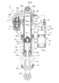
- FIG. 2 is an enlarged cross-sectional view of a solenoid valve according to one embodiment.
- FIG. 3 is an enlarged cross-sectional view of a solenoid valve according to a first modified example of the embodiment.
- the shock absorber D includes a cylinder 31, a piston rod 32 movably inserted into the cylinder 31 in the axial direction, a piston 33 dividing the cylinder 31 into an extension side chamber R1 and a compression side chamber R2, an extension side damping passage 33a and a compression side damping passage 33b provided in the piston 33 and communicating the extension side chamber R1 and the compression side chamber R2, an extension side damping valve 34 fixed to the piston rod 32 for opening and closing the extension side damping passage 33a, a compression side damping valve 35 fixed to the piston rod 32 for opening and closing the compression side damping passage 33b, a tank 36 provided on the side of the cylinder 31, an outer tube 37 covering the outer periphery of the cylinder 31, an upper cap 38 closing the upper end of the cylinder 31 and connecting the cylinder 31 and the tank 36,
- Cylinder 31 is cylindrical and has a hole 31a at its lower end in FIG. 1 that connects the inside and outside, and is inserted into outer tube 37.
- An annular gap is formed between cylinder 31 and outer tube 37, and is connected to the inside of cylinder 31 by hole 31a provided in cylinder 31.
- the upper ends of the cylinder 31 and the outer tube 37 in FIG. 1 are both closed by upper caps 38, and an annular rod guide 40 is attached to the inner circumference of the lower ends of the cylinder 31 and the outer tube 37 in FIG. 1.
- the outer tube 37 is provided with a screw portion 37a on the outer circumference of the upper end side in FIG. 1 into which an annular upper suspension spring bearing 41 and a nut 42 are screwed, and a hole 37b provided on the upper side in FIG. 1, which is the tip side of the screw portion 37a, and which connects the inside and outside of the outer tube 37.
- the upper suspension spring bearing 41 can be moved up and down relative to the outer tube 37 by rotating the screw portion 37a in the manner of a feed screw, and is fixed to the screw portion 37a by tightening the nut 42.
- the piston rod 32 has a small diameter section 32a at its upper end that is smaller in diameter than the lower section, and a bracket 32b at its lower end that can be connected to the body or wheel of a vehicle (not shown), and an annular lower suspension spring bearing 32c that is stacked above the bracket 32b.
- a cylindrical cushion 43 that abuts against the upper end of the bracket 32b is attached to the outer periphery of the lower end of the piston rod 32 in FIG. 1.
- the piston rod 32 is inserted into the cylinder 31 through the inner circumference of the rod guide 40, and its outer circumference is in sliding contact with the inner circumference of a cylindrical bush 40a fixed to the inner circumference of the rod guide 40, so that it can move in the axial direction while being guided by the rod guide 40.
- a cylindrical bush 40a fixed to the inner circumference of the rod guide 40, so that it can move in the axial direction while being guided by the rod guide 40.
- an annular seal member 40b that slides against the outer circumference of the piston rod 32 is provided on the inner circumference of the rod guide 40, and the inside of the cylinder 31 is sealed by the seal member 40b.
- the seal member 40b is provided on the inner circumference of the rod guide 40, but a seal member that seals between the cylinder 31 and the piston rod 32 may be provided below the rod guide 40 independently of the rod guide 40.
- a suspension spring 39 consisting of a coil spring arranged on the outer periphery of the outer tube 37 and the piston rod 32, and the suspension spring 39 constantly biases the piston rod 32 in a direction that moves it outward from the cylinder 31, that is, in a direction that extends the shock absorber D.
- the shock absorber D equipped with the suspension spring 39 in this way is disposed between the body and wheels of a vehicle not shown in the figure, the vehicle body is elastically supported by the suspension spring 39.
- the shock absorber D of this embodiment employs a structure in which the cushion 43 comes into contact with the rod guide 40, but a structure in which an annular stopper facing the cushion 43 is provided below the rod guide 40 in FIG. 1 and the cushion 43 comes into contact with the stopper and is compressed may also be employed.
- An annular piston 33 is attached to the small diameter portion 32a at the upper end of the piston rod 32.
- the piston 33 is annular and is attached to the outer periphery of the small diameter portion 32a of the piston rod 32 together with the extension side damping valve 34 and the compression side damping valve 35 by a piston nut 44.
- the piston 33 When the piston 33 is inserted into the cylinder 31, it divides the inside of the cylinder 31 into an extension side chamber R1 and a compression side chamber R2, which are filled with liquid, and can move axially inside the cylinder 31 together with the piston rod 32.
- the liquid filled in the extension side chamber R1 and the compression side chamber R2 is, for example, hydraulic oil, but it may be a liquid other than hydraulic oil.
- the piston 33 has an extension-side damping passage 33a and a compression-side damping passage 33b that penetrate along the axial direction, and is inserted axially movably into the cylinder 31 to divide the inside of the cylinder 31 into an extension-side chamber R1 and a compression-side chamber R2.
- the extension-side chamber R1 divided in the cylinder 31 by the piston 33 is connected to the annular gap between the cylinder 31 and the outer tube 37 via a hole 31a provided in the cylinder 31.
Landscapes
- Engineering & Computer Science (AREA)
- General Engineering & Computer Science (AREA)
- Mechanical Engineering (AREA)
- Magnetically Actuated Valves (AREA)
Applications Claiming Priority (2)
| Application Number | Priority Date | Filing Date | Title |
|---|---|---|---|
| JP2023-154048 | 2023-09-21 | ||
| JP2023154048A JP2025045955A (ja) | 2023-09-21 | 2023-09-21 | ソレノイドバルブおよびソレノイドバルブの製造方法 |
Publications (1)
| Publication Number | Publication Date |
|---|---|
| WO2025062926A1 true WO2025062926A1 (ja) | 2025-03-27 |
Family
ID=95072969
Family Applications (1)
| Application Number | Title | Priority Date | Filing Date |
|---|---|---|---|
| PCT/JP2024/029601 Pending WO2025062926A1 (ja) | 2023-09-21 | 2024-08-21 | ソレノイドバルブおよびソレノイドバルブの製造方法 |
Country Status (2)
| Country | Link |
|---|---|
| JP (1) | JP2025045955A (https=) |
| WO (1) | WO2025062926A1 (https=) |
Citations (3)
| Publication number | Priority date | Publication date | Assignee | Title |
|---|---|---|---|---|
| JPH04290685A (ja) * | 1991-03-19 | 1992-10-15 | Honda Motor Co Ltd | 油圧切換装置 |
| JP2004239433A (ja) * | 2003-01-16 | 2004-08-26 | Mitsubishi Electric Corp | 電磁弁 |
| JP2011163485A (ja) * | 2010-02-12 | 2011-08-25 | Keihin Corp | ソレノイド装置 |
Family Cites Families (1)
| Publication number | Priority date | Publication date | Assignee | Title |
|---|---|---|---|---|
| DE4024920C2 (de) * | 1990-08-06 | 1996-02-01 | Fichtel & Sachs Ag | Schwingungsdämpfer |
-
2023
- 2023-09-21 JP JP2023154048A patent/JP2025045955A/ja active Pending
-
2024
- 2024-08-21 WO PCT/JP2024/029601 patent/WO2025062926A1/ja active Pending
Patent Citations (3)
| Publication number | Priority date | Publication date | Assignee | Title |
|---|---|---|---|---|
| JPH04290685A (ja) * | 1991-03-19 | 1992-10-15 | Honda Motor Co Ltd | 油圧切換装置 |
| JP2004239433A (ja) * | 2003-01-16 | 2004-08-26 | Mitsubishi Electric Corp | 電磁弁 |
| JP2011163485A (ja) * | 2010-02-12 | 2011-08-25 | Keihin Corp | ソレノイド装置 |
Also Published As
| Publication number | Publication date |
|---|---|
| JP2025045955A (ja) | 2025-04-02 |
Similar Documents
| Publication | Publication Date | Title |
|---|---|---|
| US11761509B2 (en) | Damping force generating mechanism and pressure shock absorber | |
| US5232196A (en) | Proportional solenoid controlled valve | |
| KR101822764B1 (ko) | 액압 완충기 | |
| US4960188A (en) | Single-tube vibration damper of variable damping force | |
| US5335757A (en) | Hydraulic adjustable vibration damper | |
| JP6440861B2 (ja) | 緩衝器及び緩衝器の組立方法 | |
| CN108087481B (zh) | 复原阻尼力及压缩阻尼力独立连续调控的磁流变液减振器 | |
| CN111630295A (zh) | 阻尼阀和缓冲器 | |
| KR102862169B1 (ko) | 완충기의 제조 방법 | |
| WO2025062926A1 (ja) | ソレノイドバルブおよびソレノイドバルブの製造方法 | |
| JP7416672B2 (ja) | 減衰力調整式緩衝器及び減衰力調整弁 | |
| KR20220003099A (ko) | 감쇠력 조정식 완충기 | |
| JP2001165346A (ja) | 油圧緩衝器のソレノイド装置 | |
| US20240191768A1 (en) | Shock absorber | |
| JP2015197126A (ja) | 緩衝器 | |
| WO2023181351A1 (ja) | リアクッションユニット | |
| JP2022141301A (ja) | シリンダ装置 | |
| WO2020261701A1 (ja) | ソレノイド装置、および、それを用いた緩衝器 | |
| JP7522884B1 (ja) | 緩衝器 | |
| CN113883209B (zh) | 缓冲器以及缓冲器的组装方法 | |
| WO2024089993A1 (ja) | 緩衝器 | |
| WO2025220402A1 (ja) | 緩衝器 | |
| WO2025205342A1 (ja) | ソレノイドバルブおよび緩衝器 | |
| WO2023181350A1 (ja) | 緩衝器 | |
| WO2025142278A1 (ja) | 緩衝器 |
Legal Events
| Date | Code | Title | Description |
|---|---|---|---|
| 121 | Ep: the epo has been informed by wipo that ep was designated in this application |
Ref document number: 24866614 Country of ref document: EP Kind code of ref document: A1 |