WO2025062898A1 - 電磁継電器 - Google Patents
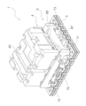
電磁継電器 Download PDFInfo
- Publication number
- WO2025062898A1 WO2025062898A1 PCT/JP2024/029176 JP2024029176W WO2025062898A1 WO 2025062898 A1 WO2025062898 A1 WO 2025062898A1 JP 2024029176 W JP2024029176 W JP 2024029176W WO 2025062898 A1 WO2025062898 A1 WO 2025062898A1
- Authority
- WO
- WIPO (PCT)
- Prior art keywords
- movable contact
- contact piece
- transmission line
- line
- ground
- Prior art date
- Legal status (The legal status is an assumption and is not a legal conclusion. Google has not performed a legal analysis and makes no representation as to the accuracy of the status listed.)
- Ceased
Links
Images



Classifications
-
- H—ELECTRICITY
- H01—ELECTRIC ELEMENTS
- H01H—ELECTRIC SWITCHES; RELAYS; SELECTORS; EMERGENCY PROTECTIVE DEVICES
- H01H50/00—Details of electromagnetic relays
- H01H50/10—Electromagnetic or electrostatic shielding
-
- H—ELECTRICITY
- H01—ELECTRIC ELEMENTS
- H01H—ELECTRIC SWITCHES; RELAYS; SELECTORS; EMERGENCY PROTECTIVE DEVICES
- H01H50/00—Details of electromagnetic relays
- H01H50/14—Terminal arrangements
-
- H—ELECTRICITY
- H01—ELECTRIC ELEMENTS
- H01H—ELECTRIC SWITCHES; RELAYS; SELECTORS; EMERGENCY PROTECTIVE DEVICES
- H01H50/00—Details of electromagnetic relays
- H01H50/16—Magnetic circuit arrangements
- H01H50/18—Movable parts of magnetic circuits, e.g. armature
Definitions
- the present invention relates to an electromagnetic relay.
- the electromagnetic relay in Patent Document 1 includes a movable contact piece, multiple fixed terminals, and a shield plate.
- the electromagnet block When the electromagnet block is turned on and the movable contact piece is pressed by the electromagnet block, both ends of the movable contact piece come into contact with the multiple fixed terminals. This allows the transmission of high-frequency signals.
- the electromagnet block is turned off and the movable contact piece is biased by the return spring, both ends of the movable contact piece leave the multiple fixed terminals and come into contact with the shield plate. This blocks the transmission of high-frequency signals.
- This type of electromagnetic relay can be configured as follows: One end of the movable contact piece is connected to a fixed terminal of the first transmission line. In this state, the movable contact piece is pressed by a pressing member, and the other end of the movable contact piece comes into contact with the fixed terminal of the second transmission line. This allows the transmission of high-frequency signals.
- one end of the movable contact piece is connected to a fixed terminal of the first transmission line, and the other end of the movable contact piece is connected to or detached from the fixed terminal of the second transmission line.
- the other end of the movable contact piece is connected to the fixed terminal of the second transmission line, the other end of the movable contact piece is positioned above the one end of the movable contact piece.
- An object of the present invention is to provide an electromagnetic relay that can improve the insulation loss characteristics.
- An electromagnetic relay includes a base block and a movable contact piece.
- the base block includes a first transmission line, a second transmission line, and a ground plate.
- the movable contact piece is connected to the first transmission line.
- the movable contact piece extends from the first transmission line toward the second transmission line.
- the movable contact piece moves between a connection position where it is connected to the second transmission line and a disconnection position where it is spaced upward from the second transmission line.
- At least a portion of the ground plate is disposed along the movable contact piece in a direction from the first transmission line toward the second transmission line.
- At least one of the ground plate and the movable contact piece is formed so that the distance between the ground plate and the movable contact piece is substantially constant when the movable contact piece is in the connection position.
- At least one of the ground plate and the movable contact piece is formed so that the distance between the ground plate and the movable contact piece is substantially constant when the movable contact piece is in the connecting position.
- the ground plate may have an inclined portion that is inclined so as to approach the movable contact piece as it moves in the above direction when viewed from above the base block.
- the movable contact piece may have an inclined portion that is inclined so as to approach the ground plate as it moves in the above direction when viewed from above the base block. This configuration makes it possible to effectively stabilize the change in impedance of the movable contact piece with a simple configuration. This makes it possible to effectively improve the insulation loss characteristics.
- the inclined portion may include a pair of inclined portions.
- the pair of inclined portions is arranged along both side surfaces of the movable contact piece when viewed from above the base block. This configuration can reliably stabilize the change in impedance of the movable contact piece. In other words, it can reliably improve the insulation loss characteristics.
- the ground plate may have an erected portion extending upward from the surface of the base block.
- the erected portion is arranged parallel to the movable contact piece when viewed from above the base block. This configuration can reliably stabilize the change in impedance of the movable contact piece. In other words, it can reliably improve the insulation loss characteristics.
- the electromagnetic relay of the present invention can improve insulation loss characteristics.
- FIG. FIG. FIG. FIG. FIG. 2 is a top view of a printed circuit board, a first movable contact piece, a second movable contact piece, and a shield plate.
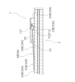
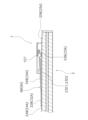
- FIG. FIG. 7 is a partially enlarged cross-sectional view taken along line VII in FIG. 6 (closed state).
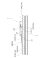
- FIG. 7 is a partially enlarged cross-sectional view taken along line VII in FIG. 6 (open state).
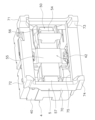
- 2 is a perspective view of the base assembly and the stand as viewed from below.
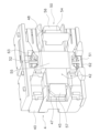
- FIG. FIG. 4 is a perspective view of the base assembly as viewed from below.
- FIG. FIG. 2 is a cross-sectional view of an electromagnetic relay in an open state.
- FIG. 2 is a cross-sectional view of an electromagnetic relay in a closed state.
- FIG. 11 is a top view of a printed circuit board, a first movable contact piece, and a second movable contact piece in another embodiment.
- FIG. 11 is a top view of a printed circuit board, a first movable contact piece, and a second movable contact piece in another embodiment.
- FIG. 7 is a partially enlarged cross-sectional view (closed state) taken along line VII in FIG. 6 in another embodiment.
- the electromagnetic relay according to this embodiment is used to switch between a high-frequency RF signal (an example of a high-frequency signal) and a low-frequency DC signal (an example of a low-frequency signal).
- the electromagnetic relay 1 includes a case 2, a base block 3, a base assembly 4, and a stand 5.
- the base block 3 includes a printed circuit board, a ceramic board, a resin molded product, a metal molded product, a flexible board, and an MID (Molded Interconnect Device).
- MID Molded Interconnect Device
- the base block 3 is a printed circuit board.
- the base block is described using the term "printed circuit board 3".
- the case 2 is omitted in FIG. 2.
- the direction in which the base assembly 4 and the stand 5 are arranged with respect to the printed circuit board 3 is defined as the upper side, and the opposite direction is defined as the lower side.
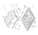
- FIG. 3 is an exploded perspective view of the electromagnetic relay 1.
- the electromagnetic relay 1 includes a first movable contact piece 6A (an example of a movable contact piece), a second movable contact piece 6B (an example of a movable contact piece), and a shield plate 7.
- the first movable contact piece 6A, the second movable contact piece 6B, and the shield plate 7 are disposed on the printed circuit board 3.
- FIG. 4 is a perspective view of the printed circuit board 3. Note that the shield plate 7 is omitted in FIG. 4.
- the printed circuit board 3 includes first to fourth conductor layers 11-14 and first to third dielectric layers 15-17.
- the first to fourth conductor layers 11-14 are made of an electrically conductive material such as copper.
- the first to third dielectric layers 15-17 are made of a dielectric material.
- the first to fourth conductor layers 11-14 and the first to third dielectric layers 15-17 are stacked alternately with each other.
- the first conductor layer 11 is provided on the upper surface of the printed circuit board 3.
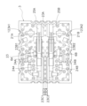
- FIG. 5 is a top view of the printed circuit board 3. Note that the shield plate 7 and the first and second movable contact pieces 6A, 6B are omitted in FIG. 5.
- the first conductor layer 11 is provided with a first RF line 21A, a second RF line 21B, a first DC line 22A, a second DC line 22B, a first ground plate 23 (an example of a ground plate), and a pair of second ground plates 123A1, 123A2.
- the first RF line 21A and the second RF line 21B are transmission lines for passing an RF signal.
- the first RF line 21A includes a first transmission line 24A (an example of a first transmission line) and a second transmission line 25A (an example of a second transmission line).
- the first transmission line 24A and the second transmission line 25A are arranged apart from each other.
- the first transmission line 24A and the second transmission line 25A are electrically isolated from each other.
- the first transmission line 24A is connected to a first input terminal 26A.
- the second transmission line 25A is connected to a first RF terminal 27A.
- the first input terminal 26A and the first RF terminal 27A are through-hole terminals provided on the end faces of the printed circuit board 3.
- the second RF line 21B includes a third transmission line 24B (an example of a first transmission line) and a fourth transmission line 25B (an example of a second transmission line).
- the third transmission line 24B and the fourth transmission line 25B are arranged apart from each other.
- the third transmission line 24B and the fourth transmission line 25B are electrically isolated from each other.
- the third transmission line 24B is connected to a second input terminal 26B.
- the fourth transmission line 25B is connected to a second RF terminal 27B.
- the second input terminal 26B and the second RF terminal 27B are each a through-hole terminal provided on an end surface of the printed circuit board 3.
- the first DC line 22A and the second DC line 22B are transmission lines for passing DC signals.
- the first DC line 22A is connected to the first transmission line 24A and the first ground plate 23.
- a first inductor 28A and a first capacitor 29A are arranged on the first DC line 22A. Note that in the drawings, only a portion of the first inductor 28A is labeled with the reference symbol 28A, and the reference symbols for the other first inductors 28A are omitted.
- the first DC line 22A is connected to the first DC terminal 30A between the first inductor 28A and the first capacitor 29A.
- the first DC terminal 30A is a through-hole terminal provided on the end surface of the printed circuit board 3.
- the first DC line 22A, the first inductor 28A, and the first capacitor 29A function as a low-pass filter that passes DC signals but cuts RF signals.
- the first inductor 28A and the first capacitor 29A are set to cut high-frequency signals of, for example, 1 kHz or higher.
- the second DC line 22B is connected to the third transmission line 24B and the first ground plate 23.
- a second inductor 28B and a second capacitor 29B are arranged on the second DC line 22B. Note that in the drawing, only a portion of the second inductor 28B is labeled with the reference symbol 28B, and the reference symbols for the other second inductors 28B are omitted.
- the second DC line 22B is connected to the second DC terminal 30B between the second inductor 28B and the second capacitor 29B.
- the second DC terminal 30B is a through-hole terminal provided on the end surface of the printed circuit board 3.
- the second DC line 22B, the second inductor 28B, and the second capacitor 29B function as a low-pass filter that passes DC signals but cuts RF signals.
- the second inductor 28B and the second capacitor 29B are set to cut high-frequency signals of, for example, 1 kHz or higher.
- the first ground plate 23 has a ground line 23A and a pair of ground portions 23B1, 23B2.
- the ground line 23A extends between the first transmission line 24A and the third transmission line 24B and along the first transmission line 24A and the third transmission line 24B.
- the ground line 23A extends between the second transmission line 25A and the fourth transmission line 25B and along the second transmission line 25A and the fourth transmission line 25B.
- the pair of ground parts 23B1, 23B2 are formed integrally with the ground line 23A.
- the pair of ground parts 23B1, 23B2 are arranged on both sides of the ground line 23A.
- the pair of ground parts 23B1, 23B2 are arranged on both sides of the first movable contact piece 6A and the second movable contact piece 6B when viewed from above the printed circuit board 3.
- the ground line 23A and the ground portion 23B1 are arranged along the first movable contact piece 6A in the longitudinal direction from the first transmission line 24A toward the second transmission line 25A.
- the ground line 23A and the ground portion 23B1 are formed so that the distance between the ground line 23A and the ground portion 23B1 and the first movable contact piece 6A is substantially constant when the first movable contact piece 6A is in the connection position.
- the ground line 23A and the ground portion 23B2 are arranged along the second movable contact piece 6B in the longitudinal direction from the third transmission line 24B to the fourth transmission line 25B.
- the ground line 23A and the ground portion 23B2 are formed so that the distance between the ground line 23A and the ground portion 23B2 and the second movable contact piece 6B is substantially constant when the second movable contact piece 6B is in the connection position.
- the ground line 23A has a first inclined portion 23A1 and a second inclined portion 23A2.
- the first inclined portion 23A1 and the second inclined portion 23A2 are provided between a pair of ground portions 23B1, 23B2 in a direction perpendicular to the longitudinal direction.
- black circles are drawn at the start and end points of the first inclined portion 23A1 and the second inclined portion 23A2.
- the first inclined portion 23A1 is provided on the side of the ground line 23A on the ground portion 23B1 side. In a top view of the printed circuit board 3, the first inclined portion 23A1 extends along the first movable contact piece 6A. In a top view of the printed circuit board 3, the first inclined portion 23A1 inclines from the outside of the first movable contact piece 6A to approach the side of the first movable contact piece 6A in the longitudinal direction from the first transmission line 24A toward the second transmission line 25A. In a top view of the printed circuit board 3, the first inclined portion 23A1 extends along the first movable contact piece 6A so as to intersect with the side of the first movable contact piece 6A. A part of the first inclined portion 23A1 is disposed below the first movable contact piece 6A.
- the second inclined portion 23A2 extends along the second movable contact piece 6B.
- the second inclined portion 23A2 inclines in the longitudinal direction from the first transmission line 24A toward the second transmission line 25A so as to approach the side of the first movable contact piece 6A from the outside of the first movable contact piece 6A.
- the second inclined portion 23A2 extends along the second movable contact piece 6B so as to intersect with the side of the second movable contact piece 6B. A portion of the second inclined portion 23A2 is disposed below the second movable contact piece 6B.
- the inclination angles of the first and second inclined portions 23A1 and 23A2 are formed so that the impedance ( ⁇ L/C) determined by the inductance component (L) and capacitance component (C) generated between them and the first ground plate 23 is constant.
- the first and second inclined portions 23A1, 23A2 are formed in the longitudinal direction within a range from the first and second connecting portions 32A, 32B of the first and second movable contact pieces 6A, 6B to the first and second contact portions 33A, 33B of the first and second movable contact pieces 6A, 6B.
- the first and second inclined portions 23A1, 23A2 are preferably formed in the longitudinal direction within a range from the first and second connecting portions 32A, 32B of the first and second movable contact pieces 6A, 6B to the base ends P1, P2 of the first and second movable contact pieces 6A, 6B.
- the ground portion 23B1 has a third inclined portion 23B11.
- the third inclined portion 23B11 is provided on a side surface of the ground portion 23B1 so as to face the first inclined portion 23A1.
- black circles are marked at the start and end points of the third inclined portion 23B11.
- the third inclined portion 23B11 extends along the first movable contact piece 6A.
- the third inclined portion 23B11 is formed symmetrically to the first inclined portion 23A1 with respect to the central axis X1 in the longitudinal direction of the first movable contact piece 6A.
- the third inclined portion 23B11 inclines from the outside of the second movable contact piece 6B toward the side of the second movable contact piece 6B in the longitudinal direction from the third transmission line 24B toward the fourth transmission line 25B when viewed from above the printed circuit board 3.
- the third inclined portion 23B11 extends along the first movable contact piece 6A so as to intersect with the side of the first movable contact piece 6A.
- a portion of the third inclined portion 23B11 is disposed below the first movable contact piece 6A.
- the first inclined portion 23A1 and the third inclined portion 23B11 are disposed along both side surfaces of the first movable contact piece 6A when viewed from above the printed circuit board 3.
- the ground portion 23B2 has a fourth inclined portion 23B21.
- the fourth inclined portion 23B21 is provided on the side of the ground portion 23B2 so as to face the second inclined portion 23A2.
- black circles are marked at the start and end points of the fourth inclined portion 23B21.
- the fourth inclined portion 23B21 extends along the second movable contact piece 6B.
- the fourth inclined portion 23B21 is formed symmetrically to the second inclined portion 23A2 with respect to the longitudinal center axis X2 of the second movable contact piece 6B.
- the fourth inclined portion 23B21 is inclined from the outside of the second movable contact piece 6B to approach the side of the second movable contact piece 6B in the longitudinal direction from the third transmission line 24B to the fourth transmission line 25B when viewed from above the printed circuit board 3.
- the fourth inclined portion 23B21 extends along the second movable contact piece 6B so as to intersect with the side of the second movable contact piece 6B.
- a portion of the fourth inclined portion 23B21 is disposed below the second movable contact piece 6B.
- the second inclined portion 23A2 and the fourth inclined portion 23B21 are disposed along both side surfaces of the second movable contact piece 6B.
- the inclination angles of the third and fourth inclined portions 23B11 and 23B21 are formed so that the impedance ( ⁇ L/C) determined by the inductance component (L) and capacitance component (C) generated between them and the first ground plate 23 is constant.
- the third and fourth inclined portions 23B11, 23B21 are formed in the longitudinal direction within the range from the first and second connection portions 32A, 32B of the first and second movable contact pieces 6A, 6B to the first and second contact portions 33A, 33B of the first and second movable contact pieces 6A, 6B.
- the third and fourth inclined portions 23B11, 23B21 are formed in the longitudinal direction within the range from the first and second connection portions 32A, 32B of the first and second movable contact pieces 6A, 6B to the base ends P1, P2 of the first and second movable contact pieces 6A, 6B.
- Each of the pair of second ground plates 123A1, 123A2 is formed separately from the first ground plate 23.
- the pair of second ground plates 123A1, 123A2 are arranged on both sides of the second transmission line 25A and the fourth transmission line 25B.
- the second transmission line 25A is arranged between the ground line 23A and the second ground plate 123A1.
- the fourth transmission line 25B is arranged between the ground line 23A and the second ground plate 123A2.
- the pair of second ground plates 123A1, 123A2 are arranged on both sides of the first movable contact piece 6A and the second movable contact piece 6B when viewed from above the printed circuit board 3.
- the second to fourth conductor layers 12-14 shown in FIG. 4 are ground layers.
- a plurality of through-hole terminals 31 are provided on the end face of the printed circuit board 3. Note that in the drawings, only some of the through-hole terminals 31 are labeled with the reference numeral 31, and the reference numerals of the other through-hole terminals 31 are omitted.
- the through-hole terminals 31 connect the first ground plate 23 and the second to fourth conductor layers 12-14 described above.
- the first movable contact piece 6A and the second movable contact piece 6B are arranged on the printed circuit board 3.
- the first movable contact piece 6A is arranged above the first RF line 21A.
- the first movable contact piece 6A extends from the first transmission line 24A toward the second transmission line 25A.
- the first movable contact piece 6A is formed in a rectangular shape that is long in one direction.
- the first movable contact piece 6A includes a first connection portion 32A, a first contact portion 33A, and a first intermediate portion 34A.
- the first connection portion 32A is connected to the first transmission line 24A.
- the first contact portion 33A is disposed above the second transmission line 25A.
- the first intermediate portion 34A is located between the first connection portion 32A and the first contact portion 33A.
- the first movable contact piece 6A can move between a connected position and a disconnected position (an example of a disconnected position). As shown in Figure 7A, when the first movable contact piece 6A is located in the connected position, the first contact portion 33A contacts the second transmission line 25A. As a result, the first movable contact piece 6A connects the first transmission line 24A and the second transmission line 25A.
- the first contact portion 33A is detached from the second transmission line 25A.
- the first movable contact piece 6A disconnects the first transmission line 24A and the second transmission line 25A.
- the first movable contact piece 6A contacts the shield plate 7 in the disconnecting position. It is preferable that the first movable contact piece 6A contacts the shield plate 7 via the insulating layer 107 in the disconnecting position.
- the insulating layer 107 is attached to the back surface of the shield plate 7.
- the first connection portion 32A of the first movable contact piece 6A is connected to the first transmission line 24A, and the first contact portion 33A of the first movable contact piece 6A is in contact with the second transmission line 25A.
- the base end portion P1 of the first contact portion 33A is positioned above the first connection portion 32A.
- the base end portion P1 of the first contact portion 33A may be interpreted as the connection portion of the first contact portion 33A and the first intermediate portion 34A.
- the bottom surface of the first movable contact piece 6A is inclined in the longitudinal direction from the first transmission line 24A to the second transmission line 25A. As the distance increases in the longitudinal direction from the first transmission line 24A to the second transmission line 25A, the distance between the first intermediate portion 34A and the first ground plate 23 gradually increases.
- the first intermediate portion 34A of the first movable contact piece 6A is disposed between the ground line 23A and the ground portion 23B1.
- a part of the first intermediate portion 34A of the first movable contact piece 6A is disposed between the first inclined portion 23A1 of the ground line 23A and the third inclined portion 23B11 of the ground portion 23B1.
- the second movable contact piece 6B is disposed above the second RF line 21B.
- the second movable contact piece 6B extends from the third transmission line 24B toward the fourth transmission line 25B.
- the second movable contact piece 6B is formed in a rectangular shape that is long in one direction.
- the second movable contact piece 6B includes a second connection portion 32B, a second contact portion 33B, and a second intermediate portion 34B.
- the second connection portion 32B is connected to the third transmission line 24B.
- the second contact portion 33B is disposed above the fourth transmission line 25B.
- the second intermediate portion 34B is located between the second connection portion 32B and the second contact portion 33B.
- the second movable contact piece 6B can move between a connection position and a disconnection position. As shown in Figure 7A, when the second movable contact piece 6B is in the connection position, the second contact portion 33B contacts the fourth transmission line 25B. As a result, the second movable contact piece 6B connects the third transmission line 24B and the fourth transmission line 25B.
- the second movable contact piece 6B when the second movable contact piece 6B is in the interrupting position, the second contact portion 33B is separated from the fourth transmission line 25B. As a result, the second movable contact piece 6B interrupts the third transmission line 24B and the fourth transmission line 25B. In this state, the second movable contact piece 6B contacts the shield plate 7 in the interrupting position. It is preferable that the second movable contact piece 6B contacts the shield plate 7 via the insulating layer 107 in the interrupting position.
- the second connection portion 32B of the second movable contact piece 6B is connected to the third transmission line 24B, and the second contact portion 33B of the second movable contact piece 6B is in contact with the fourth transmission line 25B.
- the base end portion P2 of the second contact portion 33B is positioned above the second connection portion 32B.
- the base end portion P2 of the second contact portion 33B may be interpreted as the connection portion of the second contact portion 33B and the second intermediate portion 34B.
- the bottom surface of the second movable contact piece 6B is inclined in the longitudinal direction from the third transmission line 24B to the fourth transmission line 25B. As the distance increases in the longitudinal direction from the third transmission line 24B to the fourth transmission line 25B, the distance between the second intermediate portion 34B and the first ground plate 23 gradually increases.
- the second intermediate portion 34B of the second movable contact piece 6B is disposed between the second inclined portion 23A2 of the ground line 23A and the ground portion 23B2.
- a part of the second intermediate portion 34B of the second movable contact piece 6B is disposed between the second inclined portion 23A2 of the ground line 23A and the fourth inclined portion 23B21 of the ground portion 23B2.
- the distance between the ground line 23A and the ground portion 23B1 and the first and second movable contact pieces 6A, 6B is configured to be substantially constant.
- the portions where the first to fourth inclined portions 23A1, 23A2, 23B11, and 23B21 are formed may be formed of a high dielectric material formed of a high dielectric material.
- the shield plate 7 is disposed on the printed circuit board 3. As shown in FIG. 3 and FIG. 6, the shield plate 7 is connected to the first ground plate 23. In detail, the shield plate 7 is connected to the first ground plate 23 and the pair of second ground plates 123A1, 123A2.
- the shield plate 7 is made of a conductive material.
- the shield plate 7 is disposed above the first contact portion 33A and the second contact portion 33B. That is, the first contact portion 33A is disposed between the shield plate 7 and the second transmission line 25A. The second contact portion 33B is disposed between the shield plate 7 and the fourth transmission line 25B.
- the shield plate 7 improves the isolation characteristics between the first RF line 21A and the second RF line 21B.
- Figure 8 is a perspective view of the base assembly 4 and the stand 5 as viewed from below.
- Figure 9 is a perspective view of the base assembly 4 as viewed from below.
- Figure 10 is an exploded perspective view of the base assembly 4.
- Figures 11A and 11B are cross-sectional views of the electromagnetic relay 1. As shown in Figures 8 to 10, the base assembly 4 includes a base 40, a coil block 41, and a movable block 42.
- the coil block 41 includes a coil 43, a spool 44, and an iron core 45.
- the coil 43 is wound around the spool 44.
- the iron core 45 is disposed within the coil 43.
- the iron core 45 includes an intermediate portion 46, a first suction portion 47, and a second suction portion 48.
- the intermediate portion 46 is disposed within the coil 43 and extends in the axial direction of the coil 43.
- the first suction portion 47 protrudes from the coil 43 in the axial direction of the coil 43.
- the first suction portion 47 is disposed facing downward.
- the second suction portion 48 protrudes from the coil 43 in the opposite direction to the first suction portion 47 in the axial direction of the coil 43.
- the second suction portion 48 is disposed facing downward.
- FIG. 12 is a perspective view of the movable block 42.
- the movable block 42 includes an iron piece 50, a first hinge spring 51, a second hinge spring 52, a permanent magnet 53, a card 54, and a movable insulating stand 55.
- the iron piece 50 is supported on a movable insulating base 55.
- the iron piece 50 includes a first end 56 and a second end 57.
- the first end 56 protrudes from the movable insulating base 55 in the axial direction of the coil 43.
- the first end 56 is disposed below the first suction portion 47 of the iron core 45 and faces the first suction portion 47.
- the second end 57 protrudes from the movable insulating base 55 in the opposite direction to the first end 56 in the axial direction of the coil 43.
- the second end 57 is disposed below the second suction portion 48 of the iron core 45 and faces the second suction portion 48.
- the first hinge spring 51 is supported by the movable insulating base 55.
- the first hinge spring 51 protrudes from the movable insulating base 55 toward one side of the movable insulating base 55.
- the second hinge spring 52 is supported by the movable insulating base 55.
- the second hinge spring 52 protrudes from the movable insulating base 55 toward the other side of the movable insulating base 55.
- the permanent magnet 53 is attached to the upper surface of the movable insulating base 55.
- the card 54 is supported by the movable insulating base 55.
- the card 54 protrudes downward from the movable insulating base 55.
- the card 54 is disposed above the first movable contact piece 6A and the second movable contact piece 6B.
- the card 54 is disposed above the first intermediate portion 34A of the first movable contact piece 6A and the second intermediate portion 34B of the second movable contact piece 6B.
- the card 54 is connected to the underside of the first end portion 56 of the iron piece 50.
- the card 54 protrudes downward from the underside of the first end portion 56.
- the movable insulating base 55 is supported so as to be swingable relative to the base 40.
- the base 40 includes support protrusions 58 and 59.
- the movable insulating base 55 includes support holes 60 and 61.
- the support protrusions 58 and 59 are disposed in the support holes 60 and 61, and support the movable insulating base 55 so as to be swingable.
- the base 40 includes a first support recess 62 and a second support recess 63.
- the first hinge spring 51 is disposed in the first support recess 62.
- the first hinge spring 51 is connected to the base 40 at the first support recess 62.
- the second hinge spring 52 is disposed in the second support recess 63.
- the second hinge spring 52 is connected to the base 40 at the second support recess 63.
- the movable insulating base 55 is supported on the base 40 so as to be swingable around the first hinge spring 51 and the second hinge spring 52.
- the stand 5 is disposed above the printed circuit board 3 and supports the base assembly 4. More specifically, the stand 5 supports the base 40.
- the coil block 41 is supported by the stand 5 via the base 40.
- the movable block 42 is supported by the stand 5 via the base 40.
- the stand 5 includes a frame 70 and a number of legs 71-74. As shown in FIG. 8, the frame 70 has an opening 75 in the center.
- the movable block 42 is disposed within the opening 75 of the frame 70.
- the card 54 extends downward through the opening 75.
- FIG. 11A shows the electromagnetic relay 1 in an open state.
- the coil 43 is not excited, and the iron piece 50 is not attracted to the iron core 45.
- the first end 56 of the iron piece 50 is attracted to the first attraction portion 47 of the iron core 45 by the magnetic force of the permanent magnet 53 and is in contact with the first attraction portion 47. Therefore, the card 54 is separated from the first movable contact piece 6A and the second movable contact piece 6B, and the first movable contact piece 6A and the second movable contact piece 6B are each located in the disconnection position. Therefore, in the first RF line 21A, the first transmission line 24A and the second transmission line 25A are disconnected from each other. Also, in the second RF line 21B, the third transmission line 24B and the fourth transmission line 25B are disconnected from each other.
- the electromagnetic relay 1 When a current flows through the coil 43, the electromagnetic relay 1 is in the closed state shown in FIG. 11B.
- the electromagnetic relay 1 When the electromagnetic relay 1 is in the closed state, the second end 57 of the iron piece 50 is attracted to the second attraction portion 48 of the iron core 45 by the electromagnetic force of the coil 43 and rises. This causes the iron piece 50 to swing and the first end 56 to descend.
- the card 54 descends together with the first end 56 and presses the first movable contact piece 6A and the second movable contact piece 6B, thereby moving the first movable contact piece 6A and the second movable contact piece 6B to their respective connection positions.
- This causes the first transmission line 24A and the second transmission line 25A to be connected to each other in the first RF line 21A.
- the third transmission line 24B and the fourth transmission line 25B to be connected to each other in the second RF line 21B.
- the magnetic force of the permanent magnet 53 rotates the iron piece 50 in the opposite direction, the second end 57 descends and separates from the second attraction portion 48, and the first end 56 rises.
- the card 54 rises together with the first end 56 and separates from the first movable contact piece 6A and the second movable contact piece 6B.
- the first movable contact piece 6A and the second movable contact piece 6B return to their respective disconnected positions due to the elastic forces of the first movable contact piece 6A and the second movable contact piece 6B.
- the first RF line 21A the first transmission line 24A and the second transmission line 25A are disconnected from each other.
- the third transmission line 24B and the fourth transmission line 25B are disconnected from each other.
- the electromagnetic relay 1 when an RF signal is input to the first input terminal 26A and the second input terminal 26B of the electromagnetic relay 1, the electromagnetic relay 1 is closed.
- the first transmission line 24A and the second transmission line 25A are connected to each other, and the third transmission line 24B and the fourth transmission line 25B are connected to each other. Therefore, the RF signal is output from the first input terminal 26A through the first RF line 21A to the first RF terminal 27A.
- the RF signal is output from the second input terminal 26B through the second RF line 21B to the second RF terminal 27B. Meanwhile, the RF signal is cut at the first DC line 22A and the second DC line 22B, respectively, and therefore the RF signal is prevented from being output from the first and second DC terminals 30A and 30B.
- the electromagnetic relay 1 When a DC signal is input to the first input terminal 26A and the second input terminal 26B of the electromagnetic relay 1, the electromagnetic relay 1 is opened. In this case, the first transmission line 24A and the second transmission line 25A are disconnected from each other, and the third transmission line 24B and the fourth transmission line 25B are disconnected from each other. Therefore, the DC signal is output from the first input terminal 26A through the first DC line 22A without passing through the first RF line 21A, and from the first DC terminal 30A. The DC signal is output from the second input terminal 26B through the second DC line 22B without passing through the second RF line 21B, and from the second DC terminal 30B. This prevents the DC signal from flowing to the first movable contact piece 6A and the second movable contact piece 6B.
- the first ground plate 23 is formed so that the distance between the first ground plate 23 and the first and second movable contact pieces 6A, 6B is substantially constant when the first and second movable contact pieces 6A, 6B are in the connected position.
- the change in impedance of the first and second movable contact pieces 6A, 6B can be stabilized when the first and second movable contact pieces 6A, 6B are in the connected position. This can improve the insulation loss characteristics.
- the first ground plate 23 may have a first inclined portion 23A1 and a third inclined portion 23B11 that incline toward the first movable contact piece 6A in the longitudinal direction when viewed from above the printed circuit board 3.
- the first ground plate 23 may have a second inclined portion 23A2 and a fourth inclined portion 23B21 that incline toward the second movable contact piece 6B in the longitudinal direction when viewed from above the printed circuit board 3.
- This simple configuration effectively stabilizes the impedance changes of the first and second movable contact pieces 6A and 6B. This effectively improves the insulation loss characteristics.
- the first inclined portion 23A1 and the third inclined portion 23B11 are arranged along both side surfaces of the first movable contact piece 6A when viewed from above the printed circuit board 3.
- the second inclined portion 23A2 and the fourth inclined portion 23B21 are arranged along both side surfaces of the second movable contact piece 6B when viewed from above the printed circuit board 3.
- This configuration reliably stabilizes the change in impedance of the first and second movable contact pieces 6A and 6B. In other words, it reliably improves the insulation loss characteristics.
- the first movable contact piece 6A may have inclined portions 61A1, 61A2 that are inclined so as to approach the first ground plate 23 as they move in the longitudinal direction when viewed from above the printed circuit board 3.
- the inclined portions 61A1, 61A2 are provided on both side surfaces of the first intermediate portion 34A.
- black circles are marked at the start and end points of the inclined portions 61A1, 61A2.
- the second movable contact piece 6B may have inclined portions 61B1, 61B2 that are inclined toward the first ground plate 23 as they approach the longitudinal direction when viewed from above the printed circuit board 3.
- the inclined portions 61B1, 61B2 are provided on both side surfaces of the second intermediate portion 34B. In FIG. 13, black circles are indicated at the start and end points of the inclined portions 61B1, 61B2.
- the first inclined portion 23A1 and the second inclined portion 23A2 are not formed on the ground line 23A
- the third inclined portion 23B11 is not formed on the ground portion 23B1
- the fourth inclined portion 23B21 is not formed on the ground portion 23B2. That is, instead of the first inclined portion 23A1, the second inclined portion 23A2, the third inclined portion 23B11, and the fourth inclined portion 23B21, the inclined portions 61A1 and 61A2 are formed on the first movable contact piece 6A, and the inclined portions 61B1 and 61B2 are formed on the second movable contact piece 6B.
- the formation range of the inclined portions 61A1, 61A2, 61B1, and 61B2 can be changed according to the inclination angle ⁇ .
- the first ground plate 23 may further have erected portions 23C1, 23C2, 23C3, and 23C4 extending upward from the surface of the printed circuit board 3.
- the erected portions 23C1, 23C2, 23C3, and 23C4 are arranged parallel to the first and second movable contact pieces 6A and 6B when viewed from above the printed circuit board 3.
- the erected portions 23C1, 23C2 are arranged parallel to both side surfaces of the first intermediate portion 34A of the first movable contact piece 6A.
- the erected portions 23C1, 23C2 are arranged above the first intermediate portion 34A of the first movable contact piece 6A.
- the erected portions 23C1, 23C2 are arranged above the base end portion P1 of the first contact portion 33A of the first movable contact piece 6A. It is preferable that the erected portions 23C1, 23C2 are arranged above the first contact portion 33A of the first movable contact piece 6A.
- the erected portions 23C3, 23C4 are arranged parallel to both side surfaces of the second intermediate portion 34B of the second movable contact piece 6B.
- the erected portions 23C3, 23C4 are arranged above the second intermediate portion 34B of the second movable contact piece 6B.
- the erected portions 23C3, 23C4 are arranged above the base end portion P2 of the second contact portion 33B of the second movable contact piece 6B. It is preferable that the erected portions 23C3, 23C4 are arranged above the second contact portion 33B of the second movable contact piece 6B.
- This configuration reliably stabilizes the change in impedance of the first and second movable contact pieces 6A and 6B. In other words, it reliably improves the insulation loss characteristics.
- a high dielectric 23D1 made of a high dielectric material or a metal body 23D2 may be disposed below the first and second movable contact pieces 6A, 6B, respectively.
- the upper surface of the high dielectric 23D1 or the upper surface of the metal body 23D2 is formed so as to be parallel to the lower surface of the first intermediate portion 34A of the first movable contact piece 6A and the lower surface of the second intermediate portion 34B of the second movable contact piece 6B when the first and second movable contact pieces 6A, 6B are in the connected position.
- This configuration can also improve the insulation loss characteristics.
- the configuration of the printed circuit board 3 is not limited to that of the above embodiment and may be modified.
- the configuration of the transmission lines of the printed circuit board 3 is not limited to that of the above embodiment and may be modified.
- the second RF line 21B and the second DC line 22B may be omitted.
- the configuration of the terminals of the printed circuit board 3 is not limited to that of the above embodiment and may be modified.
- the second input terminal 26B, the second RF terminal 27B, and the second DC terminal 30B may be omitted.
- the RF signal and the DC signal may be passed in the opposite direction to that of the above embodiment.
- the configuration of the base assembly 4 is not limited to that of the above embodiment and may be modified.
- the stand 5 is not limited to being separate from the base 40 and may be integrated with it.
- the electromagnetic relay of the present invention can improve insulation loss characteristics.
Landscapes
- Physics & Mathematics (AREA)
- Electromagnetism (AREA)
- Contacts (AREA)
Abstract
電磁継電器(1)は、プリント基板(3)と、第1可動接触片(6A)と、を備える。プリント基板(3)は、第1伝送線路(24A)、第2伝送線路(25A)、及びグランド板(23)を含む。第1可動接触片(6A)は、第1伝送線路(24A)に接続される。第1可動接触片(6A)は、第1伝送線路(24A)から第2伝送線路(25A)に向けて延びる。第1可動接触片(6A)は接続位置と離脱位置との間で移動する。グランド板(23)の少なくとも一部は、第1伝送線路(24A)から第2伝送線路(25A)に向かう方向において、第1可動接触片(6A)に沿って配置される。第1可動接触片(6A)が接続位置に位置する状態でグランド板(23)及び第1可動接触片(6A)の距離が実質的に一定になるように、グランド板(23)が形成される。
Description
本発明は、電磁継電器に関する。
電磁継電器には、高周波信号の伝送を開閉するためのものがある。例えば、特許文献1の電磁継電器は、可動接触片と、複数の固定端子と、シールド板と、を備えている。電磁石ブロックがオンになり可動接触片が電磁石ブロックによって押圧された場合、可動接触片の両端部が複数の固定端子に接触する。これにより、高周波信号の伝送が許可される。一方で、電磁石ブロックがオフになり可動接触片が復帰バネによって付勢された場合、可動接触片の両端部は、複数の固定端子から離脱し、シールド板に接触する。これにより、高周波信号の伝送が遮断される。
従来の電磁継電器では、可動接触片の両端部を固定端子に接触させたり、可動接触片の両端部を固定端子から離脱させたりすることによって、高周波信号の伝送が開閉される。この場合、可動接触片の全体を固定端子に接近させたり、可動接触片の全体を固定端子から離脱させたりする必要がある。この構成を実現するためには、電磁継電器の構成が複雑になるという問題がある。また、可動接触片を全体的に可動させるためには、電磁石ブロックの押圧力、すなわち、電磁石のパワーが要求されるという問題もある。
この問題を解決するために、可動接触片が全体的に可動するのではなく可動接触片が部分的に可動する電磁継電器の開発が、試みられている。このタイプの電磁継電器は、以下のように構成されうる。可動接触片の一端が第1伝送線路の固定端子に接続される。この状態で、可動接触片が押圧部材によって押圧され、可動接触片の他端が第2伝送線路の固定端子に接触する。これにより、高周波信号の伝送が許可される。
この状態で、可動接触片に対する押圧部材の押圧が解除されると、可動接触片の他端が第2伝送線路の固定端子から離脱しシールド板に接触する。これにより、高周波信号の伝送が遮断される。
このタイプの電磁継電器では、可動接触片の一端が第1伝送線路の固定端子に接続された状態で、可動接触片の他端が、第2伝送線路の固定端子に接続されたり、第2伝送線路の固定端子から離脱したりする。ここで、可動接触片の他端が第2伝送線路の固定端子に接続された状態では、可動接触片の他端は可動接触片の一端よりも上方に配置される。
このため、基板のグランド板から可動接触片までの距離が、可動接触片の一端及び可動接触片の他端の間において変化する。例えば、この距離は、第1伝送線路から第2伝送線路に向かうにつれて大きくなる。結果として、可動接触片の一端及び可動接触片の他端の間において可動接触片のインピーダンスが変化し、インサレーションロス特性が低下するおそれがある。本発明の目的は、インサレーションロス特性を向上することができる電磁継電器を、提供することにある。
本発明の一態様に係る電磁継電器は、ベースブロックと、可動接触片と、を備える。ベースブロックは、第1伝送線路、第2伝送線路、及びグランド板を含む。可動接触片は、第1伝送線路に接続される。可動接触片は、第1伝送線路から第2伝送線路に向けて延びる。可動接触片は、第2伝送線路に接続される接続位置と、第2伝送線路から上方に離れた離脱位置との間で移動する。グランド板の少なくとも一部は、第1伝送線路から第2伝送線路に向かう方向において、可動接触片に沿って配置される。可動接触片が接続位置に位置する状態でグランド板及び可動接触片の距離が実質的に一定になるように、グランド板及び可動接触片の少なくともいずれか一方が形成される。
本態様に係る電磁継電器では、可動接触片が接続位置に位置する状態でグランド板及び可動接触片の距離が実質的に一定になるように、グランド板及び可動接触片の少なくともいずれか一方が形成される。この構成によって、可動接触片が接続位置に位置する状態で、可動接触片のインピーダンスの変化を安定させることができる。これにより、インサレーションロス特性を向上することができる。
グランド板は、ベースブロックの上方視において上記の方向に向かうにつれて可動接触片に接近するように傾斜する傾斜部、を有していてもよい。この構成によって、簡単な構成で可動接触片のインピーダンスの変化を効果的に安定させることができる。これにより、インサレーションロス特性を効果的に向上することができる。
可動接触片は、ベースブロックの上方視において上記の方向に向かうにつれてグランド板に接近するように傾斜する傾斜部、を有していてもよい。この構成によって、簡単な構成で可動接触片のインピーダンスの変化を効果的に安定させることができる。これにより、インサレーションロス特性を効果的に向上することができる。
上記の傾斜部は、1対の傾斜部を含んでいてもよい。この場合、1対の傾斜部は、ベースブロックの上方視において、可動接触片の両側面に沿って配置される。この構成によって、可動接触片のインピーダンスの変化を確実に安定させることができる。すなわち、インサレーションロス特性を確実に向上することができる。
グランド板は、ベースブロックの表面から上方に延びる立設部、を有していてもよい。この場合、立設部は、ベースブロックの上方視において、可動接触片と平行に配置される。この構成によって、可動接触片のインピーダンスの変化を確実に安定させることができる。すなわち、インサレーションロス特性を確実に向上することができる。
本発明の電磁継電器では、インサレーションロス特性を向上することができる。
以下、図面を参照して実施形態にかかる電磁継電器について説明する。本実施形態に係る電磁継電器は、高周波のRF信号(高周波信号の一例)と低周波のDC信号(低周波信号の一例)とを切り替えるために用いられる。
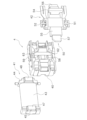
図1及び図2は、実施形態に係る電磁継電器1の斜視図である。図1及び図2に示すように、電磁継電器1は、ケース2と、ベースブロック3と、ベースアッシー4と、スタンド5とを備える。ベースブロック3は、プリント基板、セラミック基板、樹脂成型品、金属成型品、フレキシブル基板、及びMID(Molded Interconnect Device)を含む。本実施形態では、ベースブロック3がプリント基板である場合の例が示される。以下では、ベースブロックが”プリント基板3”という文言を用いて説明される。なお、図2では、ケース2は省略されている。以下の説明では、プリント基板3に対して、ベースアッシー4とスタンド5とが配置されている方向が上方、その反対の方向が下方と定義される。
図1に示すように、ケース2は、プリント基板3に取り付けられている。ケース2は、プリント基板3の上面と、ベースアッシー4と、スタンド5とを覆う。図3は、電磁継電器1の分解斜視図である。図3に示すように、電磁継電器1は、第1可動接触片6A(可動接触片の一例)と、第2可動接触片6B(可動接触片の一例)と、シールド板7とを備える。第1可動接触片6Aと、第2可動接触片6Bと、シールド板7とは、プリント基板3上に配置されている。
図4は、プリント基板3の斜視図である。なお、図4では、シールド板7は省略されている。図4に示すように、プリント基板3は、第1~第4導体層11-14と、第1~第3誘電体層15-17とを含む。第1~第4導体層11-14は、銅などの電気伝導性を有する材料製である。第1~第3誘電体層15-17は、誘電体製である。第1~第4導体層11-14と第1~第3誘電体層15-17とは、互いに交互に積層されている。
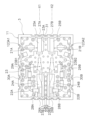
第1導体層11は、プリント基板3の上面に設けられている。図5は、プリント基板3の上面図である。なお、図5では、シールド板7と第1及び第2可動接触片6A,6Bとは省略されている。図4及び図5に示すように、第1導体層11には、第1RF線路21Aと、第2RF線路21Bと、第1DC線路22Aと、第2DC線路22Bと、第1グランド板23(グランド板の一例)と、1対の第2グランド板123A1,123A2と、が設けられている。
第1RF線路21Aと第2RF線路21Bとは、RF信号を通すための伝送路である。第1RF線路21Aは、第1伝送線路24A(第1伝送線路の一例)と第2伝送線路25A(第2伝送線路の一例)とを含む。第1伝送線路24Aと第2伝送線路25Aとは、互いに離れて配置されている。第1伝送線路24Aと第2伝送線路25Aとは、電気的に互いに遮断されている。第1伝送線路24Aは、第1入力端子26Aに接続されている。第2伝送線路25Aは、第1RF端子27Aに接続されている。第1入力端子26Aと第1RF端子27Aとは、それぞれプリント基板3の端面に設けられたスルーホール端子である。
第2RF線路21Bは、第3伝送線路24B(第1伝送線路の一例)と第4伝送線路25B(第2伝送線路の一例)とを含む。第3伝送線路24Bと第4伝送線路25Bとは、互いに離れて配置されている。第3伝送線路24Bと第4伝送線路25Bとは、電気的に互いに遮断されている。第3伝送線路24Bは、第2入力端子26Bに接続されている。第4伝送線路25Bは、第2RF端子27Bに接続されている。第2入力端子26Bと第2RF端子27Bとは、それぞれプリント基板3の端面に設けられたスルーホール端子である。
第1DC線路22Aと第2DC線路22Bとは、DC信号を通すための伝送路である。第1DC線路22Aは、第1伝送線路24Aと第1グランド板23とに接続されている。第1DC線路22A上には、第1インダクタ28Aと第1キャパシタ29Aとが配置されている。なお、図面においては、第1インダクタ28Aの一部のみに符号28Aが付されており、他の第1インダクタ28Aの符号は省略されている。
第1DC線路22Aは、第1インダクタ28Aと第1キャパシタ29Aとの間において、第1DC端子30Aに接続されている。第1DC端子30Aは、プリント基板3の端面に設けられたスルーホール端子である。第1DC線路22Aと第1インダクタ28Aと第1キャパシタ29Aとは、DC信号を通過させるが、RF信号をカットするローパスフィルターとして機能する。第1インダクタ28Aと第1キャパシタ29Aとは、例えば1kHz以上の高周波信号をカットするように設定されている。
第2DC線路22Bは、第3伝送線路24Bと第1グランド板23とに接続されている。第2DC線路22B上には、第2インダクタ28Bと第2キャパシタ29Bとが配置されている。なお、図面においては、第2インダクタ28Bの一部のみに符号28Bが付されており、他の第2インダクタ28Bの符号は省略されている。
第2DC線路22Bは、第2インダクタ28Bと第2キャパシタ29Bとの間において、第2DC端子30Bに接続されている。第2DC端子30Bは、プリント基板3の端面に設けられたスルーホール端子である。第2DC線路22Bと第2インダクタ28Bと第2キャパシタ29Bとは、DC信号を通過させるが、RF信号をカットするローパスフィルターとして機能する。第2インダクタ28Bと第2キャパシタ29Bとは、例えば1kHz以上の高周波信号をカットするように設定されている。
図4及び図5に示すように、第1グランド板23は、グランド線路23Aと、1対のグランド部23B1,23B2と、を有する。グランド線路23Aは、第1伝送線路24A及び第3伝送線路24Bの間において、第1伝送線路24A及び第3伝送線路24Bに沿って延びる。グランド線路23Aは、第2伝送線路25A及び第4伝送線路25Bの間において、第2伝送線路25A及び第4伝送線路25Bに沿って延びる。
1対のグランド部23B1,23B2は、グランド線路23Aと一体に形成される。1対のグランド部23B1,23B2は、グランド線路23Aの両側に配置される。1対のグランド部23B1,23B2は、プリント基板3の上方視において、第1可動接触片6A及び第2可動接触片6Bの両側に配置される。
グランド線路23A及びグランド部23B1は、第1伝送線路24Aから第2伝送線路25Aに向かう長手方向において、第1可動接触片6Aに沿って配置される。第1可動接触片6Aが接続位置に位置する状態で、グランド線路23A及びグランド部23B1と、第1可動接触片6Aとの距離が実質的に一定になるように、グランド線路23A及びグランド部23B1が形成される。
グランド線路23A及びグランド部23B2は、第3伝送線路24Bから第4伝送線路25Bに向かう長手方向において、第2可動接触片6Bに沿って配置される。第2可動接触片6Bが接続位置に位置する状態で、グランド線路23A及びグランド部23B2と、第2可動接触片6Bとの距離が実質的に一定になるように、グランド線路23A及びグランド部23B2が形成される。
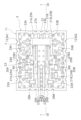
具体的には、図5及び図6に示すように、グランド線路23Aは、第1傾斜部23A1と、第2傾斜部23A2と、を有する。第1傾斜部23A1及び第2傾斜部23A2は、長手方向に直交する方向において、1対のグランド部23B1,23B2の間に設けられる。図5では、第1傾斜部23A1及び第2傾斜部23A2の始点及び終点に黒丸が記されている。
第1傾斜部23A1は、グランド部23B1側において、グランド線路23Aの側面に設けられる。プリント基板3の上方視において、第1傾斜部23A1は、第1可動接触片6Aに沿って延びる。第1傾斜部23A1は、プリント基板3の上方視において、第1伝送線路24Aから第2伝送線路25Aに向かう長手方向で、第1可動接触片6Aの外側から第1可動接触片6Aの側面に接近するように傾斜する。プリント基板3の上方視において、第1傾斜部23A1は、第1可動接触片6Aの側面と交差するように、第1可動接触片6Aに沿って延びる。第1傾斜部23A1の一部は、第1可動接触片6Aの下方に配置される。
プリント基板3の上方視において、第2傾斜部23A2は、第2可動接触片6Bに沿って延びる。第2傾斜部23A2は、プリント基板3の上方視において、第1伝送線路24Aから第2伝送線路25Aに向かう長手方向で、第1可動接触片6Aの外側から第1可動接触片6Aの側面に接近するように傾斜する。プリント基板3の上方視において、第2傾斜部23A2は、第2可動接触片6Bの側面と交差するように、第2可動接触片6Bに沿って延びる。第2傾斜部23A2の一部は、第2可動接触片6Bの下方に配置される。
図7Aに示すように第1及び第2可動接触片6A,6Bの下面が、第2伝送線路25A、第4伝送線路25Bに接触した状態において、第1グランド板23との間で生じるインダクタンス成分(L)及びキャパシタンス成分(C)によって決定されるインピーダンス(√L/C)が一定となるように、第1及び第2傾斜部23A1,23A2の傾斜角度が形成される。
第1及び第2傾斜部23A1,23A2は、長手方向において、第1及び第2可動接触片6A,6Bの第1及び第2接続部32A,32Bから、第1及び第2可動接触片6A,6Bの第1及び第2接点部33A,33Bまでの範囲内に形成される。詳細には、第1及び第2傾斜部23A1,23A2は、長手方向において、第1及び第2可動接触片6A,6Bの第1及び第2接続部32A,32Bから、第1及び第2可動接触片6A,6Bの基端部P1,P2までの範囲内に、形成されることが好ましい。
図5及び図6に示すように、グランド部23B1は、第3傾斜部23B11を有する。第3傾斜部23B11は、第1傾斜部23A1に対向するように、グランド部23B1の側面に設けられる。図5では、第3傾斜部23B11の始点及び終点に黒丸が記されている。プリント基板3の上方視において、第3傾斜部23B11は、第1可動接触片6Aに沿って延びる。図5に示すように、プリント基板3の上方視において、第3傾斜部23B11は、第1可動接触片6Aの長手方向の中心軸X1に対して、第1傾斜部23A1と対称になるように形成される。
図5及び図6に示すように、グランド部23B1は、第3傾斜部23B11を有する。第3傾斜部23B11は、第1傾斜部23A1に対向するように、グランド部23B1の側面に設けられる。図5では、第3傾斜部23B11の始点及び終点に黒丸が記されている。プリント基板3の上方視において、第3傾斜部23B11は、第1可動接触片6Aに沿って延びる。図5に示すように、プリント基板3の上方視において、第3傾斜部23B11は、第1可動接触片6Aの長手方向の中心軸X1に対して、第1傾斜部23A1と対称になるように形成される。
具体的には、図5及び図6に示すように、第3傾斜部23B11は、プリント基板3の上方視において、第3伝送線路24Bから第4伝送線路25Bに向かう長手方向で、第2可動接触片6Bの外側から第2可動接触片6Bの側面に接近するように傾斜する。プリント基板3の上方視において、第3傾斜部23B11は、第1可動接触片6Aの側面と交差するように、第1可動接触片6Aに沿って延びる。第3傾斜部23B11の一部は、第1可動接触片6Aの下方に配置される。第1傾斜部23A1及び第3傾斜部23B11は、プリント基板3の上方視において、第1可動接触片6Aの両側面に沿って配置される。
図5及び図6に示すように、グランド部23B2は、第4傾斜部23B21を有する。第4傾斜部23B21は、第2傾斜部23A2に対向するように、グランド部23B2の側面に設けられる。図5では、第4傾斜部23B21の始点及び終点に黒丸が記されている。プリント基板3の上方視において、第4傾斜部23B21は、第2可動接触片6Bに沿って延びる。図5に示すように、プリント基板3の上方視において、第4傾斜部23B21は、第2可動接触片6Bの長手方向の中心軸X2に対して、第2傾斜部23A2と対称になるように形成される。
具体的には、図5及び図6に示すように、第4傾斜部23B21は、プリント基板3の上方視において、第3伝送線路24Bから第4伝送線路25Bに向かう長手方向で、第2可動接触片6Bの外側から第2可動接触片6Bの側面に接近するように傾斜する。プリント基板3の上方視において、第4傾斜部23B21は、第2可動接触片6Bの側面と交差するように、第2可動接触片6Bに沿って延びる。第4傾斜部23B21の一部は、第2可動接触片6Bの下方に配置される。第2傾斜部23A2及び第4傾斜部23B21は、プリント基板3の上方視において、第2可動接触片6Bの両側面に沿って配置される。
図7Aに示すように第1及び第2可動接触片6A,6Bの下面が、第2伝送線路25A、第4伝送線路25Bに接触した状態において、第1グランド板23との間で生じるインダクタンス成分(L)及びキャパシタンス成分(C)によって決定されるインピーダンス(√L/C)が一定となるように、第3及び第4傾斜部23B11,23B21の傾斜角度が形成される。
第3及び第4傾斜部23B11,23B21は、長手方向において、第1及び第2可動接触片6A,6Bの第1及び第2接続部32A,32Bから、第1及び第2可動接触片6A,6Bの第1及び第2接点部33A,33Bまでの範囲内に形成される。
詳細には、第3及び第4傾斜部23B11,23B21は、長手方向において、第1及び第2可動接触片6A,6Bの第1及び第2接続部32A,32Bから、第1及び第2可動接触片6A,6Bの基端部P1,P2までの範囲内に、形成されることが好ましい。
詳細には、第3及び第4傾斜部23B11,23B21は、長手方向において、第1及び第2可動接触片6A,6Bの第1及び第2接続部32A,32Bから、第1及び第2可動接触片6A,6Bの基端部P1,P2までの範囲内に、形成されることが好ましい。
1対の第2グランド板123A1,123A2のぞれぞれは、第1グランド板23とは別体に形成される。1対の第2グランド板123A1,123A2は、第2伝送線路25A及び第4伝送線路25Bの両側に配置される。言い換えると、第2伝送線路25Aは、グランド線路23A及び第2グランド板123A1の間に、配置される。第4伝送線路25Bは、グランド線路23A及び第2グランド板123A2の間に、配置される。1対の第2グランド板123A1,123A2は、プリント基板3の上方視において、第1可動接触片6A及び第2可動接触片6Bの両側に配置される。
図4に示す第2~第4導体層12-14は、グランド層である。図4及び図5に示すように、プリント基板3の端面には、複数のスルーホール端子31が設けられている。なお、図面においては、スルーホール端子31の一部のみに符号31が付されており、他のスルーホール端子31の符号は省略されている。スルーホール端子31は、上述した第1グランド板23と第2~第4導体層12-14とを接続する。
図4及び図6に示すように、第1可動接触片6Aと第2可動接触片6Bとは、プリント基板3上に配置されている。第1可動接触片6Aは、第1RF線路21Aの上方に配置されている。第1可動接触片6Aは、第1伝送線路24Aから第2伝送線路25Aに向けて延びている。第1可動接触片6Aは、一方向に長い矩形状に形成される。
図4に示すように、第1可動接触片6Aは、第1接続部32Aと、第1接点部33Aと、第1中間部34Aを含む。第1接続部32Aは、第1伝送線路24Aに接続されている。第1接点部33Aは、第2伝送線路25Aの上方に配置されている。第1中間部34Aは、第1接続部32Aと第1接点部33Aとの間に位置する。
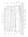
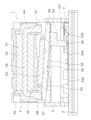
図7A及び図7Bに示すように、第1可動接触片6Aは、接続位置と遮断位置(離脱位置の一例)とに移動可能である。図7Aに示すように、第1可動接触片6Aが接続位置に位置する場合、第1接点部33Aは、第2伝送線路25Aに接触する。それにより、第1可動接触片6Aは、第1伝送線路24Aと第2伝送線路25Aとを接続する。
図7Bに示すように、第1可動接触片6Aが遮断位置に位置する場合、第1接点部33Aは、第2伝送線路25Aから離脱する。それにより、第1可動接触片6Aは、第1伝送線路24Aと第2伝送線路25Aとを遮断する。この状態において、第1可動接触片6Aは、遮断位置においてシールド板7に接触する。第1可動接触片6Aは、遮断位置において絶縁層107を介して、シールド板7に接触することが好ましい。絶縁層107は、シールド板7の裏面に装着される。
図7Aに示すように、第1可動接触片6Aの側方視において、第1可動接触片6Aの接続位置では、第1可動接触片6Aの第1接続部32Aが第1伝送線路24Aに接続され、第1可動接触片6Aの第1接点部33Aが第2伝送線路25Aに接触する。この状態では、第1接点部33Aの基端部P1は、第1接続部32Aより上方に配置される。第1接点部33Aの基端部P1は、第1接点部33A及び第1中間部34Aの接続部と解釈してもよい。
第1可動接触片6Aが接続位置に位置する場合、第1伝送線路24Aから第2伝送線路25Aに向かう長手方向において、第1可動接触片6Aの下面は傾斜する。第1伝送線路24Aから第2伝送線路25Aに向かう長手方向に向かうにつれて、第1中間部34A及び第1グランド板23の距離が徐々に大きくなる。
図5及び図6に示すように、第1可動接触片6Aの上方視において、第1可動接触片6Aの第1中間部34Aは、グランド線路23A及びグランド部23B1の間に配置される。詳細には、第1可動接触片6Aの上方視において、第1可動接触片6Aの第1中間部34Aの一部は、グランド線路23Aの第1傾斜部23A1及びグランド部23B1の第3傾斜部23B11の間に配置される。
図4及び図6に示すように、第2可動接触片6Bは、第2RF線路21Bの上方に配置されている。第2可動接触片6Bは、第3伝送線路24Bから第4伝送線路25Bに向けて延びている。第2可動接触片6Bは、一方向に長い矩形状に形成される。
図4に示すように、第2可動接触片6Bは、第2接続部32Bと、第2接点部33Bと、第2中間部34Bとを含む。第2接続部32Bは、第3伝送線路24Bに接続されている。第2接点部33Bは、第4伝送線路25Bの上方に配置されている。第2中間部34Bは、第2接続部32Bと第2接点部33Bとの間に位置する。
図7A及び図7Bに示すように、第1可動接触片6Aと同様に、第2可動接触片6Bは、接続位置と遮断位置とに移動可能である。図7Aに示すように、第2可動接触片6Bが接続位置に位置する場合、第2接点部33Bは、第4伝送線路25Bに接触する。それにより、第2可動接触片6Bは、第3伝送線路24Bと第4伝送線路25Bとを接続する。
図7Bに示すように、第2可動接触片6Bが遮断位置に位置する場合、第2接点部33Bは、第4伝送線路25Bから離脱する。それにより、第2可動接触片6Bは、第3伝送線路24Bと第4伝送線路25Bとを遮断する。この状態において、第2可動接触片6Bは、遮断位置においてシールド板7に接触する。第2可動接触片6Bは、遮断位置において絶縁層107を介して、シールド板7に接触することが好ましい。
図7Aに示すように、第2可動接触片6Bの側方視において、第2可動接触片6Bの接続位置では、第2可動接触片6Bの第2接続部32Bが第3伝送線路24Bに接続され、第2可動接触片6Bの第2接点部33Bが第4伝送線路25Bに接触する。この状態では、第2接点部33Bの基端部P2は、第2接続部32Bより上方に配置される。第2接点部33Bの基端部P2は、第2接点部33B及び第2中間部34Bの接続部と解釈してもよい。
第2可動接触片6Bが接続位置に位置する場合、第3伝送線路24Bから第4伝送線路25Bに向かう長手方向において、第2可動接触片6Bの下面は傾斜する。第3伝送線路24Bから第4伝送線路25Bに向かう長手方向に向かうにつれて、第2中間部34B及び第1グランド板23の距離が徐々に大きくなる。
図5及び図6に示すように、第2可動接触片6Bの上方視において、第2可動接触片6Bの第2中間部34Bは、グランド線路23Aの第2傾斜部23A2及びグランド部23B2の間に配置される。詳細には、第2可動接触片6Bの上方視において、第2可動接触片6Bの第2中間部34Bの一部は、グランド線路23Aの第2傾斜部23A2及びグランド部23B2の第4傾斜部23B21の間に配置される。
上記のように第1及び第2可動接触片6A,6Bを第1から第4傾斜部23A1,23A2,23B11,23B21に対して配置することによって、グランド線路23A及びグランド部23B1と、第1及び第2可動接触片6A,6Bとの距離が実質的に一定になるように構成される。なお、第1から第4傾斜部23A1,23A2,23B11,23B21が形成される部分は、高誘電材料によって形成される高誘電体によって、形成されてもよい。
図3に示すように、シールド板7は、プリント基板3上に配置されている。図3及び図6に示すように、シールド板7は、第1グランド板23に接続されている。詳細には、シールド板7は、第1グランド板23及び1対の第2グランド板123A1,123A2に接続されている。シールド板7は、導電性を有する材料で形成されている。
図6、図7A、及び図7Bに示すように、シールド板7は、第1接点部33Aと第2接点部33Bとの上方に配置されている。すなわち、第1接点部33Aは、シールド板7及び第2伝送線路25Aの間に配置される。第2接点部33Bは、シールド板7及び第4伝送線路25Bの間に配置される。シールド板7により、第1RF線路21Aと第2RF線路21Bにおけるアイソレーション特性が向上する。
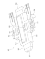
図8は、ベースアッシー4とスタンド5とを下方から見た斜視図である。図9は、ベースアッシー4を下方から見た斜視図である。図10は、ベースアッシー4の分解斜視図である。図11A及び図11Bは、電磁継電器1の断面図である。図8から図10に示すように、ベースアッシー4は、ベース40と、コイルブロック41と、可動ブロック42とを含む。
コイルブロック41は、コイル43と、スプール44と、鉄芯45とを含む。コイル43は、スプール44に巻回されている。鉄芯45は、コイル43内に配置される。鉄芯45は、中間部46と、第1吸引部47と、第2吸引部48とを含む。中間部46は、コイル43内に配置され、コイル43の軸線方向に延びている。第1吸引部47は、コイル43の軸線方向に、コイル43から突出している。第1吸引部47は、下方を向いて配置されている。第2吸引部48は、コイル43の軸線方向において、第1吸引部47と反対の方向に、コイル43から突出している。第2吸引部48は、下方を向いて配置されている。
可動ブロック42は、コイル43の電磁力によって動作することで、第1可動接触片6Aと第2可動接触片6Bとを接続位置と遮断位置との間で移動させる。図12は、可動ブロック42の斜視図である。図12に示すように、可動ブロック42は、鉄片50と、第1ヒンジバネ51と、第2ヒンジバネ52と、永久磁石53と、カード54と、可動絶縁台55と含む。
鉄片50は、可動絶縁台55に支持されている。鉄片50は、第1端部56と第2端部57とを含む。第1端部56は、コイル43の軸線方向に、可動絶縁台55から突出している。第1端部56は、鉄芯45の第1吸引部47の下方に配置されており、第1吸引部47に向かい合う。第2端部57は、コイル43の軸線方向において第1端部56と反対の方向に、可動絶縁台55から突出している。第2端部57は、鉄芯45の第2吸引部48の下方に配置されており、第2吸引部48に向かい合う。
第1ヒンジバネ51は、可動絶縁台55に支持されている。第1ヒンジバネ51は、可動絶縁台55の一側方に向かって、可動絶縁台55から突出している。第2ヒンジバネ52は、可動絶縁台55に支持されている。第2ヒンジバネ52は、可動絶縁台55の他側方に向かって、可動絶縁台55から突出している。永久磁石53は、可動絶縁台55の上面に取り付けられている。
カード54は、可動絶縁台55に支持されている。カード54は、可動絶縁台55から下方に突出している。カード54は、第1可動接触片6Aと第2可動接触片6Bとの上方に配置されている。詳細には、カード54は、第1可動接触片6Aの第1中間部34Aと、第2可動接触片6Bの第2中間部34Bとの上方に配置されている。カード54は、鉄片50の第1端部56の下面に接続されている。カード54は、第1端部56の下面から下方に突出している。
可動絶縁台55は、ベース40に対して揺動可能に支持されている。図10に示すように、ベース40は支持突起58,59を含む。図12に示すように、可動絶縁台55は、支持孔60,61を含む。支持突起58,59は、支持孔60,61内に配置され、可動絶縁台55を揺動可能に支持する。また、図10に示すように、ベース40は、第1支持凹部62と第2支持凹部63とを含む。第1ヒンジバネ51は、第1支持凹部62内に配置される。第1ヒンジバネ51は、第1支持凹部62においてベース40に接続される。第2ヒンジバネ52は、第2支持凹部63内に配置される。第2ヒンジバネ52は、第2支持凹部63においてベース40に接続される。可動絶縁台55は、第1ヒンジバネ51及び第2ヒンジバネ52回りに、揺動可能にベース40に支持される。
スタンド5は、プリント基板3の上方に配置され、ベースアッシー4を支持する。詳細には、スタンド5は、ベース40を支持する。コイルブロック41は、ベース40を介して、スタンド5に支持される。可動ブロック42は、ベース40を介して、スタンド5に支持される。スタンド5は、フレーム70と、複数の脚部71-74とを含む。図8に示すように、フレーム70には、中央部に開口75が設けられている。可動ブロック42は、フレーム70の開口75内に配置されている。カード54は、開口75を通って、下方に延びている。
次に、電磁継電器1の動作について説明する。図11Aは、開状態の電磁継電器1を示している。コイル43に電流が流されていない状態では、コイル43は励磁されておらず、鉄片50は鉄芯45に吸引されていない。永久磁石53に磁力により、鉄片50の第1端部56は、鉄芯45の第1吸引部47に吸引されて第1吸引部47に接触している。そのため、カード54は、第1可動接触片6A及び第2可動接触片6Bから離れており、第1可動接触片6Aと第2可動接触片6Bとは、それぞれ遮断位置に位置している。そのため、第1RF線路21Aにおいて、第1伝送線路24Aと第2伝送線路25Aとは互いに遮断されている。また、第2RF線路21Bにおいて、第3伝送線路24Bと第4伝送線路25Bとは互いに遮断されている。
コイル43に電流が流されている状態では、電磁継電器1は図11Bに示す閉状態となる。電磁継電器1が閉状態では、コイル43の電磁力により、鉄片50の第2端部57が、鉄芯45の第2吸引部48に吸引されて上昇する。それにより、鉄片50が揺動して、第1端部56が下降する。カード54は、第1端部56と共に下降して、第1可動接触片6Aと第2可動接触片6Bとを押圧することで、第1可動接触片6Aと第2可動接触片6Bとを、それぞれ接続位置に移動させる。それにより、第1RF線路21Aにおいて、第1伝送線路24Aと第2伝送線路25Aとは互いに接続される。また、第2RF線路21Bにおいて、第3伝送線路24Bと第4伝送線路25Bとは互いに接続される。
コイル43への電流が遮断されると、永久磁石53に磁力により、鉄片50が逆方向に回転し、第2端部57が下降して第2吸引部48から離れると共に、第1端部56が上昇する。カード54は、第1端部56と供に上昇して、第1可動接触片6Aと第2可動接触片6Bとから離れる。それにより、第1可動接触片6Aと第2可動接触片6Bとは、第1可動接触片6Aと第2可動接触片6Bとの弾性力により、それぞれ遮断位置に戻る。それにより、第1RF線路21Aにおいて、第1伝送線路24Aと第2伝送線路25Aとは互いに遮断される。また、第2RF線路21Bにおいて、第3伝送線路24Bと第4伝送線路25Bとは互いに遮断される。
例えば、電磁継電器1の第1入力端子26Aと第2入力端子26BとにRF信号が入力される場合には、電磁継電器1が閉状態とされる。この場合、第1伝送線路24Aと第2伝送線路25Aとは互いに接続され、第3伝送線路24Bと第4伝送線路25Bとは互いに接続されている。そのため、RF信号は、第1入力端子26Aから、第1RF線路21Aを通って、第1RF端子27Aから出力される。また、RF信号は、第2入力端子26Bから、第2RF線路21Bを通って、第2RF端子27Bから出力される。一方、RF信号は、第1DC線路22A、第2DC線路22Bにおいて、それぞれカットされるため、RF信号が第1、第2DC端子30A,30Bから出力されることが防止される。
電磁継電器1の第1入力端子26Aと第2入力端子26BとにDC信号が入力される場合には、電磁継電器1は開状態とされる。この場合、第1伝送線路24Aと第2伝送線路25Aとは互いに遮断され、第3伝送線路24Bと第4伝送線路25Bとは互いに遮断されている。そのため、DC信号は、第1入力端子26Aから、第1RF線路21Aを通らずに、第1DC線路22Aを通って、第1DC端子30Aから出力される。DC信号は、第2入力端子26Bから、第2RF線路21Bを通らずに、第2DC線路22Bを通って、第2DC端子30Bから出力される。それにより、DC信号が、第1可動接触片6Aと第2可動接触片6Bとに流れることが防止される。
以上説明した本実施形態に係る電磁継電器1では、第1及び第2可動接触片6A,6Bが接続位置に位置する状態で、第1グランド板23と第1及び第2可動接触片6A,6Bとの距離が実質的に一定になるように、第1グランド板23が形成される。この構成によって、第1及び第2可動接触片6A,6Bが接続位置に位置する状態で、第1及び第2可動接触片6A,6Bのインピーダンスの変化を安定させることができる。これにより、インサレーションロス特性を向上することができる。
第1グランド板23は、プリント基板3の上方視において長手方向に向かうにつれて第1可動接触片6Aに接近するように傾斜する第1傾斜部23A1及び第3傾斜部23B11、を有していてもよい。第1グランド板23は、プリント基板3の上方視において長手方向に向かうにつれて第2可動接触片6Bに接近するように傾斜する第2傾斜部23A2及び第4傾斜部23B21、を有していてもよい。
この構成によって、簡単な構成で第1及び第2可動接触片6A,6Bのインピーダンスの変化を効果的に安定させることができる。これにより、インサレーションロス特性を効果的に向上することができる。
第1傾斜部23A1及び第3傾斜部23B11は、プリント基板3の上方視において、第1可動接触片6Aの両側面に沿って配置される。第2傾斜部23A2及び第4傾斜部23B21は、プリント基板3の上方視において、第2可動接触片6Bの両側面に沿って配置される。
この構成によって、第1及び第2可動接触片6A,6Bのインピーダンスの変化を確実に安定させることができる。すなわち、インサレーションロス特性を確実に向上することができる。
以上、本発明の一実施形態について説明したが、本発明は上記実施形態に限定されるものではなく、発明の要旨を逸脱しない範囲で種々の変更が可能である。図13に示すように、第1可動接触片6Aは、プリント基板3の上方視において長手方向に向かうにつれて第1グランド板23に近づくように傾斜する傾斜部61A1,61A2、を有していてもよい。傾斜部61A1,61A2は、第1中間部34Aの両側面に設けられる。図13では、傾斜部61A1,61A2の始点及び終点に黒丸が記されている。
第2可動接触片6Bは、プリント基板3の上方視において長手方向に向かうにつれて第1グランド板23に近づくように傾斜する傾斜部61B1,61B2、を有していてもよい。傾斜部61B1,61B2は、第2中間部34Bの両側面に設けられる。図13では、傾斜部61B1,61B2の始点及び終点に黒丸が記されている。
この場合、グランド線路23Aには第1傾斜部23A1及び第2傾斜部23A2が形成されず、グランド部23B1には第3傾斜部23B11が形成されず、グランド部23B2には第4傾斜部23B21が形成されない。すなわち、第1傾斜部23A1、第2傾斜部23A2、第3傾斜部23B11、及び第4傾斜部23B21の代わりに、傾斜部61A1,61A2が第1可動接触片6Aに形成され、傾斜部61B1,61B2が第2可動接触片6Bに形成される。なお、傾斜部61A1,61A2,61B1,61B2の形成範囲は、傾斜角度αに応じて変更可能である。
このように構成しても、上記の効果と同様の効果を得ることができる。また、簡単な構成で第1及び第2可動接触片6A,6Bのインピーダンスの変化を効果的に安定させることができる。これにより、インサレーションロス特性を効果的に向上することができる。
図14に示すように、第1グランド板23は、プリント基板3の表面から上方に延びる立設部23C1,23C2,23C3,23C4、をさらに有していてもよい。この場合、立設部23C1,23C2,23C3,23C4は、プリント基板3の上方視において、第1及び第2可動接触片6A,6Bと平行に配置される。
詳細には、立設部23C1,23C2は、第1可動接触片6Aの第1中間部34Aの両側面と平行に配置される。立設部23C1,23C2は、第1可動接触片6Aの第1中間部34Aより上方に配置される。立設部23C1,23C2は、第1可動接触片6Aの第1接点部33Aの基端部P1より上方に配置される。立設部23C1,23C2は、第1可動接触片6Aの第1接点部33Aより上方に配置されることが好ましい。
立設部23C3,23C4は、第2可動接触片6Bの第2中間部34Bの両側面と平行に配置される。立設部23C3,23C4は、第2可動接触片6Bの第2中間部34Bより上方に配置される。立設部23C3,23C4は、第2可動接触片6Bの第2接点部33Bの基端部P2より上方に配置される。立設部23C3,23C4は、第2可動接触片6Bの第2接点部33Bより上方に配置されることが好ましい。
この構成によって、第1及び第2可動接触片6A,6Bのインピーダンスの変化を確実に安定させることができる。すなわち、インサレーションロス特性を確実に向上することができる。
図15に示すように、高誘電材料によって形成される高誘電体23D1、又は金属体23D2が、第1及び第2可動接触片6A,6Bのそれぞれの下方に配置されてもよい。この場合、第1及び第2可動接触片6A,6Bが接続位置に位置する状態において、第1可動接触片6Aの第1中間部34Aの下面、及び、第2可動接触片6Bの第2中間部34Bの下面と平行になるように、高誘電体23D1の上面又は金属体23D2の上面が形成されることが好ましい。このように構成しても、インサレーションロス特性を向上することができる。
以上、本発明の一実施形態について説明したが、本発明は上記実施形態に限定されるものではなく、発明の要旨を逸脱しない範囲で種々の変更が可能である。
プリント基板3の構成は、上記の実施形態のものに限らず、変更されてもよい。プリント基板3の伝送線路の構成は、上記の実施形態のものに限らず、変更されてもよい。例えば、第2RF線路21Bと第2DC線路22Bとは、省略されてもよい。プリント基板3の端子の構成は、上記の実施形態のものに限らず、変更されてもよい。例えば、第2入力端子26Bと、第2RF端子27Bと、第2DC端子30Bとは、省略されてもよい。RF信号及びDC信号は、前記実施形態とは逆方向に流されてもよい。ベースアッシー4の構成は、上記の実施形態のものに限らず、変更されてもよい。例えば、スタンド5は、ベース40と別体に限らず、一体であってもよい。
本発明の電磁継電器では、インサレーションロス特性を向上することができる。
2:ケース、 3:プリント基板、 6A:第1可動接触片、6B:第2可動接触片、 7:シールド板、 23:第1グランド板、 23A:グランド線路、 23B1,23B2:グランド部、 24A:第1伝送線路、 25A:第2伝送線路、 123A1,123A2:第2グランド板、 23A1;第1傾斜部、 23A2;第2傾斜部、 23B11;第3傾斜部、 23B21;第4傾斜部、 23C1,23C2,23C3,23C4;立設部、23D1;高誘電体、 23D2;金属体
Claims (5)
- 第1伝送線路、第2伝送線路、及びグランド板を含むベースブロックと、
前記第1伝送線路に接続され、前記第1伝送線路から前記第2伝送線路に向けて延び、前記第2伝送線路に接続される接続位置と、前記第2伝送線路から上方に離れた離脱位置との間で移動する可動接触片と、
を備え、
前記グランド板の少なくとも一部は、前記第1伝送線路から前記第2伝送線路に向かう方向において、前記可動接触片に沿って配置され、
前記可動接触片が前記接続位置に位置する状態で前記グランド板及び前記可動接触片の距離が実質的に一定になるように、前記グランド板及び前記可動接触片の少なくともいずれか一方が形成される、
電磁継電器。
- 前記グランド板は、前記ベースブロックの上方視において前記方向に向かうにつれて前記可動接触片に接近するように傾斜する傾斜部、を有する、
請求項1に記載の電磁継電器。
- 前記可動接触片は、前記ベースブロックの上方視において前記方向に向かうにつれて前記グランド板に接近するように傾斜する傾斜部、を有する、
請求項1に記載の電磁継電器。
- 前記傾斜部は、1対の傾斜部を含み、
前記1対の傾斜部は、前記ベースブロックの上方視において、前記可動接触片の両側面に沿って配置される、
請求項2又は3に記載の電磁継電器。
- 前記グランド板は、前記ベースブロックの表面から上方に延びる立設部、を有し、
前記立設部は、前記ベースブロックの上方視において、前記可動接触片と平行に配置される、
請求項1に記載の電磁継電器。
Applications Claiming Priority (2)
| Application Number | Priority Date | Filing Date | Title |
|---|---|---|---|
| JP2023-153962 | 2023-09-20 | ||
| JP2023153962A JP2025045912A (ja) | 2023-09-20 | 2023-09-20 | 電磁継電器 |
Publications (1)
| Publication Number | Publication Date |
|---|---|
| WO2025062898A1 true WO2025062898A1 (ja) | 2025-03-27 |
Family
ID=95072695
Family Applications (1)
| Application Number | Title | Priority Date | Filing Date |
|---|---|---|---|
| PCT/JP2024/029176 Ceased WO2025062898A1 (ja) | 2023-09-20 | 2024-08-16 | 電磁継電器 |
Country Status (3)
| Country | Link |
|---|---|
| JP (1) | JP2025045912A (ja) |
| TW (1) | TW202514686A (ja) |
| WO (1) | WO2025062898A1 (ja) |
Citations (3)
| Publication number | Priority date | Publication date | Assignee | Title |
|---|---|---|---|---|
| JP2003051234A (ja) * | 2001-05-30 | 2003-02-21 | Omron Corp | 電磁継電器 |
| WO2010110315A1 (ja) * | 2009-03-24 | 2010-09-30 | パナソニック電工株式会社 | 伝送線路 |
| JP2011086500A (ja) * | 2009-10-15 | 2011-04-28 | Nidec Copal Electronics Corp | マイクロリレー |
-
2023
- 2023-09-20 JP JP2023153962A patent/JP2025045912A/ja active Pending
-
2024
- 2024-08-16 WO PCT/JP2024/029176 patent/WO2025062898A1/ja not_active Ceased
- 2024-08-16 TW TW113130781A patent/TW202514686A/zh unknown
Patent Citations (3)
| Publication number | Priority date | Publication date | Assignee | Title |
|---|---|---|---|---|
| JP2003051234A (ja) * | 2001-05-30 | 2003-02-21 | Omron Corp | 電磁継電器 |
| WO2010110315A1 (ja) * | 2009-03-24 | 2010-09-30 | パナソニック電工株式会社 | 伝送線路 |
| JP2011086500A (ja) * | 2009-10-15 | 2011-04-28 | Nidec Copal Electronics Corp | マイクロリレー |
Also Published As
| Publication number | Publication date |
|---|---|
| TW202514686A (zh) | 2025-04-01 |
| JP2025045912A (ja) | 2025-04-02 |
Similar Documents
| Publication | Publication Date | Title |
|---|---|---|
| US9076615B2 (en) | Method of forming an integrated electromechanical relay | |
| US5321380A (en) | Low profile printed circuit board | |
| US6806801B2 (en) | High frequency relay | |
| US20240395488A1 (en) | Contact part and relay | |
| JP4294590B2 (ja) | 電気機械マイクロスイッチ装置 | |
| JP2025045912A (ja) | 電磁継電器 | |
| WO2025062899A1 (ja) | 電磁継電器 | |
| WO2025062897A1 (ja) | 電磁継電器 | |
| WO2025062914A1 (ja) | 電磁継電器 | |
| JP2025045917A (ja) | 電磁継電器 | |
| WO2025062916A1 (ja) | 電磁継電器 | |
| WO2025062917A1 (ja) | 回路部品 | |
| WO2025062913A1 (ja) | 電磁継電器 | |
| JP2025045914A (ja) | 電磁継電器 | |
| JP2025045919A (ja) | 電磁継電器 | |
| JP2011086500A (ja) | マイクロリレー | |
| US20050174187A1 (en) | Non-reciprocal circuit device including multilayer board | |
| CN112103138A (zh) | 一种具有柔性印刷线路触点带的射频开关及其制造方法 | |
| KR20240084359A (ko) | 평면형 변압기 | |
| GB2633966A (en) | Sidewall plating of circuit boards for layer transition connections | |
| JP2004328388A (ja) | デュアルモード・バンドパスフィルタ装置 | |
| CN110176343A (zh) | 线圈电子组件 | |
| JP2000201045A (ja) | 電源フィルタ | |
| JPS63181223A (ja) | 電力開閉器 |
Legal Events
| Date | Code | Title | Description |
|---|---|---|---|
| 121 | Ep: the epo has been informed by wipo that ep was designated in this application |
Ref document number: 24867979 Country of ref document: EP Kind code of ref document: A1 |
|
| NENP | Non-entry into the national phase |
Ref country code: DE |