WO2025062846A1 - タイヤ耐久予測装置、プログラム及びタイヤ耐久予測方法 - Google Patents
タイヤ耐久予測装置、プログラム及びタイヤ耐久予測方法 Download PDFInfo
- Publication number
- WO2025062846A1 WO2025062846A1 PCT/JP2024/027386 JP2024027386W WO2025062846A1 WO 2025062846 A1 WO2025062846 A1 WO 2025062846A1 JP 2024027386 W JP2024027386 W JP 2024027386W WO 2025062846 A1 WO2025062846 A1 WO 2025062846A1
- Authority
- WO
- WIPO (PCT)
- Prior art keywords
- tire
- durability
- information
- tread
- prediction
- Prior art date
- Legal status (The legal status is an assumption and is not a legal conclusion. Google has not performed a legal analysis and makes no representation as to the accuracy of the status listed.)
- Ceased
Links
Images

Classifications
-
- B—PERFORMING OPERATIONS; TRANSPORTING
- B60—VEHICLES IN GENERAL
- B60C—VEHICLE TYRES; TYRE INFLATION; TYRE CHANGING; CONNECTING VALVES TO INFLATABLE ELASTIC BODIES IN GENERAL; DEVICES OR ARRANGEMENTS RELATED TO TYRES
- B60C11/00—Tyre tread bands; Tread patterns; Anti-skid inserts
- B60C11/24—Wear-indicating arrangements
-
- B—PERFORMING OPERATIONS; TRANSPORTING
- B60—VEHICLES IN GENERAL
- B60C—VEHICLE TYRES; TYRE INFLATION; TYRE CHANGING; CONNECTING VALVES TO INFLATABLE ELASTIC BODIES IN GENERAL; DEVICES OR ARRANGEMENTS RELATED TO TYRES
- B60C19/00—Tyre parts or constructions not otherwise provided for
-
- B—PERFORMING OPERATIONS; TRANSPORTING
- B60—VEHICLES IN GENERAL
- B60C—VEHICLE TYRES; TYRE INFLATION; TYRE CHANGING; CONNECTING VALVES TO INFLATABLE ELASTIC BODIES IN GENERAL; DEVICES OR ARRANGEMENTS RELATED TO TYRES
- B60C19/00—Tyre parts or constructions not otherwise provided for
- B60C19/12—Puncture preventing arrangements
-
- G—PHYSICS
- G01—MEASURING; TESTING
- G01M—TESTING STATIC OR DYNAMIC BALANCE OF MACHINES OR STRUCTURES; TESTING OF STRUCTURES OR APPARATUS, NOT OTHERWISE PROVIDED FOR
- G01M17/00—Testing of vehicles
- G01M17/007—Wheeled or endless-tracked vehicles
- G01M17/02—Tyres
-
- G—PHYSICS
- G08—SIGNALLING
- G08G—TRAFFIC CONTROL SYSTEMS
- G08G1/00—Traffic control systems for road vehicles
Definitions
- This disclosure relates to a tire durability prediction device, a program, and a tire durability prediction method.
- Patent Document 1 discloses a tire management device that includes a deterioration state prediction means that predicts the deterioration tendency and deterioration state of tires mounted on a vehicle for each mounting position.
- the tire management device of Patent Document 1 appropriately manages tires to average the period of use of each tire, but there is a demand for predicting the remaining durability of tires with sufficient accuracy through simple calculations using less data.
- the deterioration state of a base tire at the time when the tire tread is completely worn down may be estimated to determine whether or not the tire can be retreaded, and the lifespan of the tire may be estimated.
- Retreading here refers to scraping the surface of the tire tread rubber and applying new rubber to reuse the tire.
- the base tire is the part of the tire (the part to be reused) excluding the tread portion that is replaced in the retreading process. Furthermore, when making such estimates, actual measurement data of the vehicle on which the target tire is mounted is often not available.
- the purpose of this disclosure is to provide a tire durability prediction device, program, and tire durability prediction method that can predict the remaining durability of a tire even if actual measurement data of the vehicle on which the target tire is mounted is not available.
- a tire durability prediction device An acquisition unit that acquires input data including information on a time or a mileage until the tire tread is completely worn out and information on a destination and a frequency of a vehicle equipped with the tire; A generating unit that generates data related to speed for each destination based on the input data; and a predictor configured to predict a remaining life of the tire at a time when the tire's tread will be completely worn down based on data relating to the speed.
- the generation unit generates data regarding a load for each of the vehicles or each of the destinations,
- the prediction unit predicts the remaining durability of the tire at the time when the tread of the tire is completely worn down based on the speed data and the load data.
- the input data includes at least one of information on a type of cargo, a vehicle type, and an axle load;
- the generation unit generates data regarding the load based on at least one piece of information of the type of cargo, the vehicle model, and the axle load.
- the input data includes temperature information;
- the generation unit calculates an average temperature according to a travel season or a travel area of the vehicle,
- the prediction unit corrects the predicted remaining durability of the tire based on the average temperature.
- the prediction unit classifies the tire into one of a plurality of categories based on the predicted remaining durability of the tire.
- the prediction unit predicts the remaining durability of the tire at the time when the tread of the tire is completely worn away, using different models depending on the mounting position of the tire.
- a program Obtaining input data including information on the time or distance traveled until the tread of a tire is completely worn out and information on the destination and frequency of a vehicle equipped with said tire; generating data relating to speed for each of the destinations based on the input data; and predicting the remaining life of the tire at the time the tire's tread is completely worn based on the speed data.
- a tire durability prediction method executed by a tire durability prediction device, comprising: The tire durability prediction device, Obtaining input data including information on the time or distance traveled until the tread of a tire is completely worn out and information on the destination and frequency of a vehicle equipped with said tire; generating data relating to speed for each of the destinations based on the input data; and predicting the remaining life of the tire at the time the tire's tread is completely worn based on the speed data.
- the present disclosure provides a tire durability prediction device, program, and tire durability prediction method that can predict the remaining durability of a tire even if actual measurement data of the vehicle on which the target tire is mounted is not available.
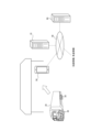
- FIG. 1 is a diagram illustrating an example of the configuration of a tire durability prediction system including a tire durability prediction device according to an embodiment of the present disclosure.
- FIG. 2 is another diagram showing an example of the configuration of the tire durability prediction system of FIG.
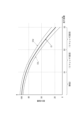
- FIG. 3 is a diagram illustrating a predicted durability index.
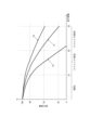
- FIG. 4 is a diagram illustrating the difference in predicted durability index depending on conditions.
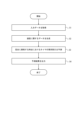
- FIG. 5 is an example of a flowchart showing the process of a tire durability prediction method according to an embodiment of the present disclosure.
- FIGS. 1 and 2 are diagrams showing an example of the configuration of a tire durability prediction system.
- the tire durability prediction system includes a tire durability prediction device 10.
- FIG. 1 is a block diagram including an example of the internal configuration of the tire durability prediction device 10.
- FIG. 2 shows the overall configuration of the tire durability prediction system.
- the tire durability prediction device 10 predicts the deterioration state of the tire 30 mounted on the vehicle 20.
- the prediction of the deterioration state is, in other words, a prediction of the remaining durability (remaining durability) of the tire 30 at a certain point in time.
- the prediction of the deterioration state of the tire 30 may be used to determine whether a specific task can be performed at a certain point in time, and in this embodiment, it is described as being used to determine whether the tire 30 can be retreaded. As described above, retreading refers to scraping the surface of the tread rubber of the tire 30 and attaching new rubber to reuse the tire.
- the durability of the tire 30 is described as the durability of the base tire.
- the tire durability prediction device 10 can use a durability index, as described below, to indicate the durability predicted to remain at a certain point in time, for example, as a numerical value (score) or a rank.
- the durability index is a relative index with a new tire 30 (at the time of initial manufacture) being 100.
- the vehicle 20 equipped with the tire 30 to be predicted may be, for example, a passenger car, truck, bus, or construction vehicle, and is not limited to a specific type of moving body.
- the vehicle 20 is described as a truck.
- the tire durability prediction system accumulates information on multiple vehicles 20.
- multiple vehicles 20 are managed by one organization (e.g., a company) and are used to carry out work, loading, or unloading at a specific location (e.g., a factory).
- the tire durability prediction device 10 includes a communication unit 11, a memory unit 12, and a control unit 13.
- the control unit 13 includes an acquisition unit 131, a generation unit 132, a prediction unit 133, and an output unit 134.
- the tire durability prediction device 10 may be, for example, a computer as a hardware configuration.
- the computer may be a server computer or a portable computer such as a laptop or tablet. Details of the components of the tire durability prediction device 10 will be described later.
- the tire durability prediction device 10 may be a computer at a location where the tire 30 is retreaded.
- the tire durability prediction device 10 may not be a single device, but may be composed of multiple devices that are located at multiple locations and can send and receive data to each other via a network 40.
- the tire durability prediction device 10 may function as the tire durability prediction device 10 shown in FIG. 1 as a whole. Therefore, for example, the tire durability prediction device 10 may be composed of a single computer as a hardware configuration, or may be composed of multiple computers connected by a network 40. When multiple computers are used, the storage unit 12 may be a shared memory that can be accessed by each computer.
- the tire durability prediction device 10 may constitute a tire durability prediction system together with devices connected via a network 40.
- the network 40 may be, for example, the Internet.
- the network 40 may also be configured to include, for example, a LAN (Local Area Network) in part.
- the tire durability prediction system may further include a terminal device 50 used by an operator who performs retreading, etc.
- the terminal device 50 is, for example, a general-purpose mobile terminal such as a smartphone or a tablet terminal, but is not limited to these.
- the terminal device 50 may function as a display unit that displays the durability prediction results or the judgment results such as whether or not retreading is possible, output by the output unit 134 described later.
- the tire durability prediction system may also be configured to include a storage device 90 (storage device 90 on the cloud) on the network 40 as viewed from the tire durability prediction device 10.
- the storage device 90 includes a database that stores information about the vehicle 20 or information about the state of the tire 30.
- the information about the vehicle 20 or the information about the state of the tire 30 may be input using the terminal device 50 by a worker at a place where the tire 30 is retreaded and the vehicle 20 is inspected and repaired (hereinafter simply referred to as the "repair place").
- a worker at the repair place may obtain information about the vehicle 20 or information about the state of the tire 30, input it using the terminal device 50, and the input information may be stored in the database.
- the input information about the state of the tire 30 is actual data of the tire 30 that has actually been used, and may include information about the life until the tire becomes a waste tire and time-series data of the actual measured value of the wear of the tread that can be used for generating a model described later.
- the worker at the repair place may input information obtained by hearing using the terminal device 50 and store it in the storage device 90.
- the information obtained by hearing is, for example, information heard from the manager of the vehicle 20, and may include information about the destination and frequency of the vehicle 20 described later.
- the information obtained by hearing may include information about the vehicle 20, such as the maximum load capacity and the weight of the vehicle body.
- the tire durability prediction device 10 may obtain information from a database, map information, temperature information, and the like via the network 40.
- the communication unit 11 includes one or more communication modules that connect to the network 40.
- the communication unit 11 may include a communication module that supports mobile communication standards such as 4G (4th Generation) and 5G (5th Generation).
- the communication unit 11 may include a communication module that supports wired or wireless LAN standards.
- the storage unit 12 is one or more memories.
- the memory may be, for example, a semiconductor memory, a magnetic memory, or an optical memory, but is not limited to these and may be any type of memory.
- the storage unit 12 is, for example, built into the tire durability prediction device 10, but may also be configured to be accessed from outside by the tire durability prediction device 10 via any interface.
- the storage unit 12 stores various data used in the various calculations performed by the control unit 13.
- the storage unit 12 may also store the results and intermediate data of the various calculations performed by the control unit 13.
- the memory unit 12 may temporarily store various information from the database of the storage device 90 on the cloud that is acquired via the communication unit 11.
- the control unit 13 is one or more processors.
- the processor may be, for example, a general-purpose processor or a dedicated processor specialized for a particular process, but is not limited to these and may be any processor.
- the control unit 13 controls the overall operation of the tire durability prediction device 10.
- the acquisition unit 131 can obtain a value of "100,000 km" as the distance traveled until the tread of the tire 30 is completely worn out based on the performance data.
- the average driving speed of the same type of vehicle 20 in the performance data can be used to convert the distance traveled and the time into each other, so the time until the tread of the tire 30 is completely worn out may be acquired.
- the information on the destination and frequency of the vehicle 20 equipped with the tire 30 is data for knowing how the vehicle 20 is used.
- multiple vehicles 20 are managed by one organization (e.g., a company) and move to a specific location (e.g., a factory).
- a specific location e.g., a factory
- information may be obtained that the destination is Factory A and the frequency is 100%.
- information may be obtained that the destination is Factory A or Factory B, and 75% of the vehicles 20 go to Factory A and the remaining 25% of the vehicles 20 go to Factory B.
- Such information may be obtained, for example, by hearing from the manager of the vehicle 20 (as oral information).
- the input data acquired by the acquisition unit 131 may include map information.
- the input data acquired by the acquisition unit 131 may include temperature information.
- the map information and temperature information may be obtained from an information providing device via the network 40.
- the information providing device is, for example, a computer that provides a service of providing information.
- the input data acquired by the acquisition unit 131 may include at least one of the following information: the type of cargo, the vehicle model, and the axle load of the vehicle 20.
- the information on the type of cargo, the vehicle model, and the axle load may be obtained, for example, by a worker at the repair site from the manager of the vehicle 20 and stored in the storage device 90 using the terminal device 50.
- the type of cargo may be, for example, beverages, food, building materials, etc.
- the vehicle model may be, for example, a four-wheeled or six-wheeled truck.
- the axle load information may be, for example, one ton per axle. Instead of the axle load, information on the loading rate may be obtained.
- the generating unit 132 generates data on the speed of the vehicle 20 for each destination based on the input data.
- the data on the speed is, for example, an average speed, but is not limited to this.
- the generating unit 132 identifies a route from the starting point of the vehicle 20 (for example, a company parking lot) to the destination (for example, Factory A or Factory B) using, for example, map information.
- the generating unit 132 may calculate the average speed based on the legal speed on the route for each destination. For example, if the route to Factory A includes a highway, the average speed will be faster than the route to Factory B, which includes only general roads. In this way, the generating unit 132 generates data on the speed of the vehicle 20 for each destination.
- the speed of each destination may be obtained as oral information by hearing.
- the generating unit 132 may use the speed of each destination obtained as input data as it is as the data on the speed of each destination.
- the generating unit 132 may generate data on the load for each vehicle 20 or each destination.
- the data on the load is, for example, an average load, but is not limited to this.
- the average load may be indicated by the weight for one tire 30, or may be indicated as a ratio to the load (standard load) assumed in the model used for prediction in the predicting unit 133.
- the generating unit 132 may generate data on the load based on at least one of the information on the type of cargo, the vehicle type, and the axle load. At this time, it becomes possible to consider the load based on verbal information, not on actual measurement.
- the average load may be calculated by dividing the axle load by the number of tires 30 per axle using the information on the axle load and the vehicle type.
- the type of cargo is, for example, beverages
- transportation is generally performed at the maximum load, so the average load may be calculated based on the information on the maximum load and the vehicle type.
- the generating unit 132 may calculate an average temperature according to the travel period or travel area of the vehicle 20.
- the generating unit 132 may calculate the average temperature by averaging the temperatures in the area including the route from the departure point of the vehicle 20 to the destination based on the temperature information. Furthermore, if the travel period of the vehicle 20 is limited (for example, only in summer), only the temperature information corresponding to the travel period may be used in calculating the average temperature.
- the prediction unit 133 predicts the remaining durability of the tire 30 at the time when the tread of the tire 30 is completely worn down, based on the data regarding the speed.
- the input data acquired by the acquisition unit 131 does not include actual measurement data of the vehicle 20.
- the data regarding the speed is generated by the generation unit 132 based on the input data. Therefore, the tire durability prediction device 10 can predict the remaining durability of the tire 30 even if actual measurement data of the vehicle 20 on which the target tire 30 is mounted is not available.
- FIG. 3 is a diagram illustrating an example of a durability index predicted by the prediction unit 133.
- the prediction unit 133 uses the durability index as the durability of the tire 30.
- a characteristic curve C1 is shown as a prediction of the durability index (vertical axis) of the base tire against the mileage (horizontal axis).
- the durability index of the tire 30 decreases with an increase in the mileage of the vehicle 20, that is, with the passage of time, as shown by the characteristic curve C1 in FIG. 3.
- the characteristic curve C1 is obtained by setting conditions that affect the durability index in a model that shows the change in the durability index of the tire 30.
- the conditions that affect the durability index include at least the speed of the vehicle 20, and correspond to the data on the speed (average speed) generated by the generation unit 132 in this embodiment.
- the durability index indicated by the characteristic curve C1 decreases significantly.
- the characteristic curve C1 may be calculated using a model generated by a known method.
- the model may be generated by machine learning using performance data stored in a database as learning data, or it may be a theoretical formula (mathematical model) whose coefficients are determined using performance data.
- the mileage D1 corresponds to the mileage until the tread of the tire 30 is completely worn out (e.g., 100,000 km).
- D2 corresponds to the mileage until the tread is completely worn out after the first retreading of the tire 30 (e.g., 200,000 km).
- D3 corresponds to the mileage until the tread is completely worn out after the second retreading of the tire 30 (e.g., 300,000 km).
- the remaining durability of the tire 30 (value of the durability index of the base tire) predicted at the points D1, D2, D3, etc. is used in the determination described below. In other words, the determination described below is efficiently performed in units of the mileage or time until the tread of the tire 30 is completely worn out (e.g., in units of 100,000 km).
- the prediction unit 133 may calculate a characteristic curve C1 corresponding to the average temperature. In this embodiment, the prediction unit 133 corrects the predicted remaining durability of the tire 30 based on the average air temperature. For example, when the average air temperature is significantly higher than the air temperature assumed in the model, the prediction unit 133 may weight the characteristic curve C1 so as to increase the slope (see characteristic curve C2 in Figure 4). At this time, taking the air temperature into account, the remaining durability of the tire 30 can be predicted more accurately.
- the prediction unit 133 may determine whether or not retreading is possible or the number of times retreading is possible based on the predicted remaining durability of the tire 30.
- the prediction unit 133 may determine whether or not retreading is possible or the number of times retreading is possible using a predetermined lower limit of the durability index at which retreading is possible. At this time, it is possible to directly indicate whether or not retreading is possible, which is information that the worker performing the retreading wants to know.
- the lower limit of the durability index may be 20. In the example of FIG. 3, it is predicted that the durability index will fall below 20 at the time D3 when the second retreading is performed and the tread is completely worn out.
- the prediction unit 133 determines that a third retreading is not possible. In other words, the prediction unit 133 determines that the number of times retreading is possible is two.
- the variation of the prediction may be taken into consideration.
- the upper limit characteristic curve C1U and the lower limit characteristic curve C1L according to the set probability may be calculated using a standard deviation or the like.
- a further condition may be added, such as that the durability index of the lower limit characteristic curve C1L does not fall below 0. For example, in the example of FIG.
- the prediction unit 133 determines that two retreads are possible. However, if the durability index of the lower limit characteristic curve C1L falls below 0 at time D3, the prediction unit 133 determines that a second retread is not possible and that the number of possible retreads is one.
- the prediction unit 133 may classify the tire 30 into one of a number of categories based on the predicted remaining durability of the tire 30.
- the categories may be, for example, rank A if the remaining durability is 80 or more, rank B if it is 50 or more but less than 80, rank C if it is 20 or more but less than 50, and rank D if it is less than 20.
- rank A indicates that there is almost no damage to the base tire. Therefore, with information such as "rank A at time D1", a worker at the repair site can understand that the tire 30 is predicted to be in good condition at time D1, even without obtaining a specific remaining durability value.
- the prediction unit 133 may use different models depending on the mounting position of the tire 30 to predict the remaining durability of the tire 30 at the time when the tread of the tire 30 is completely worn. At this time, the mounting position of the tire 30 can be taken into consideration to more accurately predict the remaining durability of the tire 30.
- FIG. 4 illustrates a characteristic curve C3 based on a different model.
- the load on the tire 30 is different for the front wheels, the inner rear wheels, and the outer rear wheels.
- the rear wheels have a double tire configuration, and the outer side refers to the side of the vehicle 20.
- the characteristic curve C3 calculated using a model corresponding to the tire 30 mounted on the outer rear wheel has a more gradual decrease in durability index than the characteristic curve C1 corresponding to the front wheel.
- the output unit 134 may output the prediction result or judgment result of the prediction unit 133 (e.g., whether or not retreading is possible) to a terminal device 50 or the like used by the worker who performs the retreading.
- the prediction result may be, for example, a change (graph) in the durability index as shown in FIG. 3 or FIG. 4.
- the worker may create a retreading work plan or the like based on the displayed prediction result or judgment result.
- the worker may also estimate the life of the tire 30 and create a procurement plan to secure the required number of tires 30.
- the worker may also plan a rotation to change the mounting position of the tire 30.
- the worker may also create a plan to have a tire 30 used by one business operator used by another business operator in order to make effective use of tires 30 that have sufficient durability.
- FIG. 5 is an example of a flowchart showing the processing of the tire durability prediction method executed by the tire durability prediction device 10.
- the program stored in the memory unit 12 may be read by the processor of the control unit 13, and the processor functioning as the acquisition unit 131, the generation unit 132, the prediction unit 133, and the output unit 134 may execute each process of FIG. 5.
- the acquisition unit 131 acquires input data including at least information on the time or distance traveled until the tread of the tire 30 is completely worn down, and information on the destination and frequency of the vehicle 20 on which the tire 30 is mounted (step S1).
- the generation unit 132 generates data regarding speed for each destination based on the input data (step S2).
- the prediction unit 133 predicts the remaining durability of the tire 30 at the time when the tread of the tire 30 is completely worn down based on the data regarding the speed (step S3).
- the output unit 134 outputs the prediction result of the prediction unit 133 to a terminal device 50 or the like used by the worker who will perform the retreading (step S4).
- the output unit 134 may output the judgment result of the prediction unit 133 (e.g., whether or not retreading is possible).
- the tire durability prediction device 10, program, and tire durability prediction method according to this embodiment can predict the remaining durability of a tire 30 even if actual measurement data of the vehicle 20 on which the target tire 30 is mounted is not available due to the above configuration.
- actual measurement data of individual vehicles 20 is not required, it is possible to predict the remaining durability of tires 30 collectively for multiple vehicles 20 managed by a single company, for example.
Landscapes
- Engineering & Computer Science (AREA)
- Mechanical Engineering (AREA)
- Physics & Mathematics (AREA)
- General Physics & Mathematics (AREA)
- Tires In General (AREA)
- Traffic Control Systems (AREA)
Abstract
タイヤ耐久予測装置(10)は、タイヤのトレッドが完全に摩耗するまでの時間又は走行距離の情報と、タイヤが装着された車両の行先及び頻度の情報と、を含む入力データを取得する取得部(131)と、入力データに基づいて、行先毎の速度に関するデータを生成する生成部(132)と、速度に関するデータに基づいて、タイヤのトレッドが完全に摩耗する時点におけるタイヤの残存耐久を予測する予測部(133)と、を備える。
Description
本開示は、タイヤ耐久予測装置、プログラム及びタイヤ耐久予測方法に関する。
従来、走行中の車両で検出されるデータを取得して、タイヤの劣化に関する推定を行うシステムが知られている。例えば特許文献1は、車両に装着されたタイヤの劣化傾向及び劣化状態を装着位置毎に予測する劣化状態予測手段を含むタイヤ管理装置を開示する。
ここで、特許文献1のタイヤ管理装置は各タイヤの使用期間の平均化のためにタイヤを適切に管理するが、より少ないデータを用いる簡易な計算によってタイヤの残存耐久を十分な精度で予測したいとの要求がある。例えばタイヤのトレッドが完全に摩耗した時点での台タイヤの劣化状態を推定して、リトレッドの可否を判定して、タイヤの寿命などを見積もることがある。ここで、リトレッドは、タイヤのトレッドゴムの表面を削って、新しいゴムを貼り付けて再利用(リユース)することである。台タイヤは、リトレッドにおいて交換されるトレッド部を除いた、タイヤの部分(再利用される部分)である。また、このような見積もりを行う場合に、対象のタイヤを装着する車両の実測データが得られていないことも多い。
かかる事情に鑑みてなされた本開示の目的は、対象のタイヤを装着する車両の実測データが得られていなくてもタイヤの残存耐久を予測可能なタイヤ耐久予測装置、プログラム及びタイヤ耐久予測方法を提供することにある。
(1)本開示の一実施形態に係るタイヤ耐久予測装置は、
タイヤのトレッドが完全に摩耗するまでの時間又は走行距離の情報と、前記タイヤが装着された車両の行先及び頻度の情報と、を含む入力データを取得する取得部と、
前記入力データに基づいて、前記行先毎の速度に関するデータを生成する生成部と、
前記速度に関するデータに基づいて、前記タイヤのトレッドが完全に摩耗する時点における前記タイヤの残存耐久を予測する予測部と、を備える。
タイヤのトレッドが完全に摩耗するまでの時間又は走行距離の情報と、前記タイヤが装着された車両の行先及び頻度の情報と、を含む入力データを取得する取得部と、
前記入力データに基づいて、前記行先毎の速度に関するデータを生成する生成部と、
前記速度に関するデータに基づいて、前記タイヤのトレッドが完全に摩耗する時点における前記タイヤの残存耐久を予測する予測部と、を備える。
(2)本開示の一実施形態として、(1)において、
前記生成部は、前記車両毎又は前記行先毎の荷重に関するデータを生成し、
前記予測部は、前記速度に関するデータ及び前記荷重に関するデータに基づいて、前記タイヤのトレッドが完全に摩耗する時点における前記タイヤの残存耐久を予測する。
前記生成部は、前記車両毎又は前記行先毎の荷重に関するデータを生成し、
前記予測部は、前記速度に関するデータ及び前記荷重に関するデータに基づいて、前記タイヤのトレッドが完全に摩耗する時点における前記タイヤの残存耐久を予測する。
(3)本開示の一実施形態として、(2)において、
前記入力データは、積荷の種類、車型及び軸重の少なくとも1つの情報を含み、
前記生成部は、前記積荷の種類、前記車型及び前記軸重の少なくとも1つの情報に基づいて、前記荷重に関するデータを生成する。
前記入力データは、積荷の種類、車型及び軸重の少なくとも1つの情報を含み、
前記生成部は、前記積荷の種類、前記車型及び前記軸重の少なくとも1つの情報に基づいて、前記荷重に関するデータを生成する。
(4)本開示の一実施形態として、(1)から(3)のいずれかにおいて、
前記入力データは、気温情報を含み、
前記生成部は、前記車両の走行時期又は走行地域に応じた平均気温を算出し、
前記予測部は、前記平均気温に基づいて、予測した前記タイヤの残存耐久を補正する。
前記入力データは、気温情報を含み、
前記生成部は、前記車両の走行時期又は走行地域に応じた平均気温を算出し、
前記予測部は、前記平均気温に基づいて、予測した前記タイヤの残存耐久を補正する。
(5)本開示の一実施形態として、(1)から(4)のいずれかにおいて、
前記予測部は、予測した前記タイヤの残存耐久に基づいて、リトレッドの可否又はリトレッドの可能回数を判定する。
前記予測部は、予測した前記タイヤの残存耐久に基づいて、リトレッドの可否又はリトレッドの可能回数を判定する。
(6)本開示の一実施形態として、(1)から(5)のいずれかにおいて、
前記予測部は、予測した前記タイヤの残存耐久に基づいて、前記タイヤを複数の区分のいずれかに分類する。
前記予測部は、予測した前記タイヤの残存耐久に基づいて、前記タイヤを複数の区分のいずれかに分類する。
(7)本開示の一実施形態として、(1)から(6)のいずれかにおいて、
前記予測部は、前記タイヤの装着位置に応じて異なるモデルを用いて、前記タイヤのトレッドが完全に摩耗する時点における前記タイヤの残存耐久を予測する。
前記予測部は、前記タイヤの装着位置に応じて異なるモデルを用いて、前記タイヤのトレッドが完全に摩耗する時点における前記タイヤの残存耐久を予測する。
(8)本開示の一実施形態に係るプログラムは、
タイヤ耐久予測装置に、
タイヤのトレッドが完全に摩耗するまでの時間又は走行距離の情報と、前記タイヤが装着された車両の行先及び頻度の情報と、を含む入力データを取得することと、
前記入力データに基づいて、前記行先毎の速度に関するデータを生成することと、
前記速度に関するデータに基づいて、前記タイヤのトレッドが完全に摩耗する時点における前記タイヤの残存耐久を予測することと、を実行させる。
タイヤ耐久予測装置に、
タイヤのトレッドが完全に摩耗するまでの時間又は走行距離の情報と、前記タイヤが装着された車両の行先及び頻度の情報と、を含む入力データを取得することと、
前記入力データに基づいて、前記行先毎の速度に関するデータを生成することと、
前記速度に関するデータに基づいて、前記タイヤのトレッドが完全に摩耗する時点における前記タイヤの残存耐久を予測することと、を実行させる。
(9)本開示の一実施形態に係るタイヤ耐久予測方法は、
タイヤ耐久予測装置が実行するタイヤ耐久予測方法であって、
前記タイヤ耐久予測装置が、
タイヤのトレッドが完全に摩耗するまでの時間又は走行距離の情報と、前記タイヤが装着された車両の行先及び頻度の情報と、を含む入力データを取得することと、
前記入力データに基づいて、前記行先毎の速度に関するデータを生成することと、
前記速度に関するデータに基づいて、前記タイヤのトレッドが完全に摩耗する時点における前記タイヤの残存耐久を予測することと、を含む。
タイヤ耐久予測装置が実行するタイヤ耐久予測方法であって、
前記タイヤ耐久予測装置が、
タイヤのトレッドが完全に摩耗するまでの時間又は走行距離の情報と、前記タイヤが装着された車両の行先及び頻度の情報と、を含む入力データを取得することと、
前記入力データに基づいて、前記行先毎の速度に関するデータを生成することと、
前記速度に関するデータに基づいて、前記タイヤのトレッドが完全に摩耗する時点における前記タイヤの残存耐久を予測することと、を含む。
本開示によれば、対象のタイヤを装着する車両の実測データが得られていなくてもタイヤの残存耐久を予測可能なタイヤ耐久予測装置、プログラム及びタイヤ耐久予測方法を提供することができる。
以下、図面を参照して本開示の一実施形態に係るタイヤ耐久予測装置10(図1参照)、プログラム及びタイヤ耐久予測方法が説明される。各図中、同一又は相当する部分には、同一符号が付されている。本実施形態の説明において、同一又は相当する部分については、説明を適宜省略又は簡略化する。
図1及び図2は、タイヤ耐久予測システムの構成例を示す図である。タイヤ耐久予測システムは、タイヤ耐久予測装置10を含む。図1はタイヤ耐久予測装置10の内部構成例を含むブロック図である。図2はタイヤ耐久予測システムの全体構成を示す。
本実施形態に係るタイヤ耐久予測装置10は車両20に装着されるタイヤ30の劣化状態を予測する。劣化状態の予測は、換言するとタイヤ30のある時点で残存している耐久度(残存耐久)の予測である。タイヤ30の劣化状態の予測は、ある時点で特定の作業などが実行可能かを判定するために使用されてよく、本実施形態においてタイヤ30のリトレッドの可否の判定に用いられるとして説明する。上記のように、リトレッドは、タイヤ30のトレッドゴムの表面を削って、新しいゴムを貼り付けて再利用することである。例えば台タイヤの損傷、化学的な劣化及び機械的な劣化がそれぞれ十分に小さい場合に、十分な耐久度が残っているとして、リトレッドが可能であると判定され得る。本実施形態においてタイヤ30の耐久度は、台タイヤの耐久度であるとして説明する。
タイヤ耐久予測装置10は後述するように耐久指標を用いて、ある時点で残存していると予測される耐久度を例えば数値(スコア)又はランクで示すことが可能である。耐久指標は新品(最初の製造時)のタイヤ30を100とする相対的な指標である。ここで、予測の対象であるタイヤ30を装着する車両20は例えば乗用自動車、トラック、バス又は建設車両などであってよく、特定種類の移動体に限定されない。本実施形態において、車両20はトラックであるとして説明される。また、図2において重複して図示することを回避するため、車両20が1台だけ示されているが、タイヤ耐久予測システムは複数の車両20の情報が蓄積される。本実施形態において、複数の車両20は、1つの組織(例えば会社)によって管理されて特定の場所(例えば工場)での作業、搬入又は搬出を行うために用いられる。
タイヤ耐久予測装置10は、通信部11と、記憶部12と、制御部13と、を備える。制御部13は、取得部131と、生成部132と、予測部133と、出力部134と、を備える。タイヤ耐久予測装置10は、ハードウェア構成として、例えばコンピュータであってよい。コンピュータは、サーバコンピュータであってよいし、ラップトップ又はタブレットのように可搬のコンピュータであってよい。タイヤ耐久予測装置10の構成要素の詳細については後述する。例えばタイヤ耐久予測装置10はタイヤ30のリトレッドを行う場所のコンピュータであってよい。ここで、タイヤ耐久予測装置10は1つの装置でなく、複数の場所に配置されて互いにネットワーク40でデータの送受信が可能な複数の装置で構成されてよい。つまり、ネットワーク40で接続される複数の装置が、全体として図1に示されるタイヤ耐久予測装置10として機能してよい。したがって、例えばタイヤ耐久予測装置10は、ハードウェア構成として、1つのコンピュータで構成されてよいし、ネットワーク40で接続された複数のコンピュータで構成されてよい。複数のコンピュータで構成される場合に、記憶部12はそれぞれのコンピュータがアクセス可能な共有メモリなどであってよい。
タイヤ耐久予測装置10は、ネットワーク40で接続される装置とともに、タイヤ耐久予測システムを構成してよい。ネットワーク40は例えばインターネットである。また、ネットワーク40は、例えば一部においてLAN(Local Area Network)を含んで構成されてよい。ここで、タイヤ耐久予測システムは、さらにリトレッドなどを行う作業者が用いる端末装置50を含んで構成されてよい。端末装置50は、例えばスマートフォン又はタブレット端末などの汎用の移動端末であるが、これらに限定されない。端末装置50は、後述する出力部134によって出力される耐久度の予測結果又はリトレッド可否などの判定結果を表示する表示部として機能してよい。また、タイヤ耐久予測システムは、タイヤ耐久予測装置10から見てネットワーク40上にある記憶装置90(クラウド上の記憶装置90)を含んで構成されてよい。本実施形態において、記憶装置90は、車両20に関する情報又はタイヤ30の状態に関する情報を記憶するデータベースを含む。車両20に関する情報又はタイヤ30の状態に関する情報は、タイヤ30のリトレッド並びに車両20の点検及び修理を行う場所(以下、単に「修理場所」という)の作業者によって端末装置50を用いて入力されてよい。例えば定期点検のために車両20が修理場所に来た場合に、修理場所の作業者が車両20に関する情報又はタイヤ30の状態に関する情報を取得して、端末装置50を用いて入力し、入力された情報がデータベースに蓄積されてよい。入力されるタイヤ30の状態に関する情報は、実際に使用されたタイヤ30の実績データであって、廃タイヤになるまでの寿命に関する情報及び後述するモデルの生成に使用可能なトレッドの摩耗の実測値の時系列データなどを含んでよい。また、修理場所の作業者は、端末装置50を用いて、ヒアリングによって得られた情報を入力して記憶装置90に記憶させてよい。ヒアリングによって得られた情報は、例えば車両20の管理者から聞いた情報であって、後述する車両20の行先及び頻度の情報などを含んでよい。また、ヒアリングによって得られた情報は、最大積載量及び車体の重量などの車両20に関する情報を含んでよい。また、タイヤ耐久予測装置10は、データベースからの情報、地図情報、気温情報などをネットワーク40経由で取得してよい。
以下、タイヤ耐久予測装置10の構成要素の詳細が説明される。通信部11は、ネットワーク40に接続する1つ以上の通信モジュールを含んで構成される。通信部11は、例えば4G(4th Generation)、5G(5th Generation)などの移動体通信規格に対応する通信モジュールを含んでよい。通信部11は、例えば有線又は無線のLAN規格に対応する通信モジュールを含んでよい。
記憶部12は、1つ以上のメモリである。メモリは、例えば半導体メモリ、磁気メモリ、又は光メモリ等であるが、これらに限られず任意のメモリとすることができる。記憶部12は、例えばタイヤ耐久予測装置10に内蔵されるが、任意のインターフェースを介してタイヤ耐久予測装置10によって外部からアクセスされる構成も可能である。
記憶部12は、制御部13が実行する各種の算出において使用される各種のデータを記憶する。また、記憶部12は、制御部13が実行する各種の算出の結果及び中間データを記憶してよい。
本実施形態において、記憶部12は、通信部11を介して取得されたクラウド上の記憶装置90のデータベースからの各種情報を一時的に記憶してよい。
制御部13は、1つ以上のプロセッサである。プロセッサは、例えば汎用のプロセッサ、又は特定の処理に特化した専用プロセッサであるが、これらに限られず任意のプロセッサとすることができる。制御部13は、タイヤ耐久予測装置10の全体の動作を制御する。
ここで、タイヤ耐久予測装置10は、以下のようなソフトウェア構成を有してよい。タイヤ耐久予測装置10の動作の制御に用いられる1つ以上のプログラムが記憶部12に記憶される。記憶部12に記憶されたプログラムは、制御部13のプロセッサによって読み込まれると、制御部13を取得部131、生成部132、予測部133及び出力部134として機能させる。
取得部131は、タイヤ30のトレッドが完全に摩耗するまでの時間又は走行距離の情報と、タイヤ30が装着された車両20の行先及び頻度の情報と、を含む入力データを取得する。ここで、完全に摩耗するとは車両20の走行に適さない状態まで摩耗することを意味する。完全に摩耗したタイヤ30は、台タイヤがリトレッド可能な耐久度を有する場合にリトレッドされて継続使用されるが、台タイヤがリトレッドできない場合に廃タイヤとなる。タイヤ30のトレッドが完全に摩耗するまでの時間又は走行距離の情報は、データベースに蓄積された実績データから取得される。つまり、予測対象のタイヤ30を装着した車両20と同種の車両20(例えば同じ会社のトラック)の過去の点検データなどに基づいて得ることができる。例えば取得部131は、実績データに基づいて、タイヤ30のトレッドが完全に摩耗するまでの走行距離として「10万km」という値を得ることができる。ここで、実績データにおける同種の車両20の平均走行速度を用いて、走行距離と時間とは互いに換算できるため、タイヤ30のトレッドが完全に摩耗するまでの時間が取得されてよい。また、タイヤ30が装着された車両20の行先及び頻度の情報は、車両20の使われ方を知るためのデータである。上記のように、本実施形態において、複数の車両20は、1つの組織(例えば会社)によって管理されて特定の場所(例えば工場)に移動する。例えば1台の車両20について、行先がA工場であって、頻度が100%といった情報が得られてよい。また、複数の車両20について、行先がA工場又はB工場であって、頻度として75%の車両20がA工場に、残りの25%の車両20がB工場に行くといった情報が得られてよい。このような情報は、例えば車両20の管理者からのヒアリングで(口頭情報として)得られる。
取得部131が取得する入力データは地図情報を含んでよい。また、取得部131が取得する入力データは気温情報を含んでよい。地図情報及び気温情報は、ネットワーク40経由で情報提供装置から得られてよい。情報提供装置は、例えば情報を提供するサービスを行うコンピュータである。また、取得部131が取得する入力データは車両20の積荷の種類、車型及び軸重の少なくとも1つの情報を含んでよい。積荷の種類、車型及び軸重の情報は、例えば修理場所の作業者が車両20の管理者から聞いて、端末装置50を用いて記憶装置90に記憶させたものであってよい。積荷の種類は、例えば飲料、食品、建材などである。車型は、例えば4輪又は6輪のトラックなどである。軸重の情報は、1軸当たり1トンなどである。軸重に代えて、積載率の情報が得られてよい。
生成部132は、入力データに基づいて、車両20の行先毎の速度に関するデータを生成する。速度に関するデータは例えば平均速度であるが、これに限定されない。生成部132は、例えば地図情報を用いて、車両20の出発地点(例えば会社の駐車場)から行先(例えばA工場又はB工場)までの経路を特定する。生成部132は、行先毎の経路における法定速度に基づいて平均速度を算出してよい。例えばA工場までの経路に高速道路が含まれる場合に、一般道のみのB工場までの経路に比べて、平均速度は速くなる。このように生成部132は、車両20の行先毎の速度に関するデータを生成する。ここで、行先毎の速度が、ヒアリングによって口頭情報として得られることがある。この場合に、生成部132は、入力データとして得られる行先毎の速度を、そのまま行先毎の速度に関するデータとして用いてよい。
生成部132は、車両20毎又は行先毎の荷重に関するデータを生成してよい。荷重に関するデータは例えば平均荷重であるが、これに限定されない。また、平均荷重は1つのタイヤ30に対する重量などで示されてよいが、予測部133における予測で用いられるモデルで想定している荷重(標準荷重)に対する比で示されてよい。ここで、生成部132は積荷の種類、車型及び軸重の少なくとも1つの情報に基づいて、荷重に関するデータを生成してよい。このとき、実測によらず、口頭情報に基づいて荷重を考慮することが可能になる。例えば軸重と車型の情報を用いて、1つの車軸当たりのタイヤ30の本数で軸重を割ることによって平均荷重が算出されてよい。また、積荷の種類が例えば飲料である場合に、一般に最大積載量での運搬が行われるため、最大積載量と車型の情報に基づいて平均荷重が算出されてよい。
生成部132は、車両20の走行時期又は走行地域に応じた平均気温を算出してよい。生成部132は、気温情報に基づいて、車両20の出発地点から行先までの経路を含む地域の気温を平均して、平均気温を算出してよい。また、車両20の走行時期が限定されている(例えば夏季のみ)場合に、平均気温を算出において、走行時期に該当する気温情報のみが用いられてよい。
予測部133は、速度に関するデータに基づいて、タイヤ30のトレッドが完全に摩耗する時点におけるタイヤ30の残存耐久を予測する。上記のように、取得部131が取得する入力データは車両20の実測データを含まない。また、速度に関するデータは、生成部132によって入力データに基づいて生成される。よって、タイヤ耐久予測装置10は、対象のタイヤ30を装着する車両20の実測データが得られていなくてもタイヤ30の残存耐久を予測することができる。
図3は、予測部133によって予測される耐久指標を例示する図である。本実施形態において、予測部133はタイヤ30の耐久度として耐久指標を用いる。図3の例において、走行距離(横軸)に対する台タイヤの耐久指標(縦軸)の予測として特性曲線C1が示されている。タイヤ30の耐久指標は、図3の特性曲線C1のように、車両20の走行距離の増加、すなわち時間の経過とともに減少する。特性曲線C1は、タイヤ30の耐久指標の変化を示すモデルに、耐久指標に影響する条件を設定することで得られる。耐久指標に影響する条件は、少なくとも車両20の速度を含み、本実施形態において生成部132によって生成された速度に関するデータ(平均速度)が対応する。車両20の平均速度が速い場合に、特性曲線C1が示す耐久指標は大きく低下する。一方、車両20の平均速度が遅い場合に、特性曲線C1が示す耐久指標の低下は緩やかになる。ここで、特性曲線C1は公知の手法によって生成されるモデルを用いて算出されてよい。例えばモデルは、データベースに蓄積された実績データを学習データとして用いる機械学習によって生成されてよいし、実績データを用いて係数が決定される理論式(数学モデル)などであってよい。
図3の例において、走行距離のD1はタイヤ30のトレッドが完全に摩耗するまでの走行距離(例えば10万km)に対応する。また、D2はタイヤ30に1回目のリトレッドが行われて、そのトレッドが完全に摩耗するまでの走行距離(例えば20万km)に対応する。また、D3はタイヤ30に2回目のリトレッドが行われて、そのトレッドが完全に摩耗するまでの走行距離(例えば30万km)に対応する。D1、D2、D3などの時点で予測されるタイヤ30の残存耐久(台タイヤの耐久指標の値)が後述する判定で用いられる。つまり、タイヤ30のトレッドが完全に摩耗するまでの走行距離又は時間を単位として(例えば10万km単位で)、効率的に後述の判定が行われる。
ここで、耐久指標に影響する他の条件として、荷重を挙げることができる。予測部133は、生成部132によって荷重に関するデータ(平均荷重)が生成された場合に、平均荷重に応じた特性曲線C1を算出してよい。つまり、予測部133は、速度に関するデータ及び荷重に関するデータに基づいて、タイヤ30のトレッドが完全に摩耗する時点におけるタイヤ30の残存耐久を予測してよい。このとき、荷重を考慮して、より正確にタイヤ30の残存耐久を予測することができる。平均荷重が重い場合に、特性曲線C1が示す耐久指標は大きく低下する。一方、平均荷重が軽い場合に、特性曲線C1が示す耐久指標の低下は緩やかになる。
また、耐久指標に影響する他の条件として、温度を挙げることができる。予測部133は、生成部132によって上記の平均温度が生成された場合に、平均温度に応じた特性曲線C1を算出してよい。本実施形態において、予測部133は、平均気温に基づいて、予測したタイヤ30の残存耐久を補正する。予測部133は、例えば平均気温がモデルで想定されている気温に比べて著しく高い場合に、特性曲線C1の傾きを大きくするように重みづけを行ってよい(図4の特性曲線C2参照)。このとき、気温を考慮して、より正確にタイヤ30の残存耐久を予測することができる。
予測部133は、予測したタイヤ30の残存耐久に基づいて、リトレッドの可否又はリトレッドの可能回数を判定してよい。予測部133は、予め定められたリトレッドが可能な耐久指標の下限を用いて、リトレッドの可否又はリトレッドの可能回数を判定してよい。このとき、リトレッドを行う作業者が知りたい情報であるリトレッドの可否などを直接的に示すことができる。例えば耐久指標の下限は20であってよい。図3の例において、2回目のリトレッドが行われて、そのトレッドが完全に摩耗するD3の時点で耐久指標が20を下回ると予測されている。したがって、予測部133は3回目のリトレッドが不可であると判定する。換言すると、予測部133はリトレッドの可能回数が2回であると判定する。ここで、より慎重な判定のために、予測(特性曲線C1)のばらつきが考慮されてよい。例えば標準偏差などを用いて、設定した確率に応じた上限特性曲線C1U及び下限特性曲線C1Lが算出されてよい。この場合に、リトレッドの可否の判定において、さらに下限特性曲線C1Lの耐久指標が0を下回らないといった判定条件が加えられてよい。例えば図3の例においてD3の時点で下限特性曲線C1Lの耐久指標が0以上であるため、予測部133は2回のリトレッドが可能と判定する。ただし、D3の時点で下限特性曲線C1Lの耐久指標が0を下回っていれば、予測部133は2回目のリトレッドが不可能で、リトレッドの可能回数が1回であると判定する。
ここで、予測部133は、予測したタイヤ30の残存耐久に基づいて、タイヤ30を複数の区分のいずれかに分類してよい。複数の区分は、例えば残存耐久が80以上であればランクA、50以上で80未満であればランクB、20以上で50未満であればランクC、20未満であればランクDなどであってよい。このとき、例えばリトレッドを行う作業者などに、タイヤ30の残存耐久をわかりやすく示すことができる。例えばランクAは、台タイヤの損傷などがほとんどないことを示す。そのため、「D1の時点でランクA」などの情報によって、修理場所の作業者は具体的な残存耐久の値を得なくても、D1の時点でのタイヤ30が良好な状態と予測されたことを理解する。
ここで、予測部133は、タイヤ30の装着位置に応じて異なるモデルを用いて、タイヤ30のトレッドが完全に摩耗する時点におけるタイヤ30の残存耐久を予測してよい。このとき、タイヤ30の装着位置を考慮して、より正確にタイヤ30の残存耐久を予測することができる。例えば図4は、異なるモデルに基づく特性曲線C3を例示する。一般にタイヤ30への負荷は、前輪、後輪内側及び後輪外側で異なる。ここで、後輪はダブルタイヤ構成であって、外側が車両20の側面の側を指す。例えば後輪外側に装着される場合に、タイヤ30への負荷は前輪、後輪内側に比べて小さくなる。そのため、後輪外側に装着されるタイヤ30に対応するモデルを用いて算出された特性曲線C3は、前輪に対応する特性曲線C1に比べて、耐久指標の低下が緩やかである。
出力部134は、予測部133の予測結果又は判定結果(例えばリトレッドの可否)を、リトレッドを行う作業者が用いる端末装置50などに出力してよい。予測結果は、例えば図3又は図4に示されるような耐久指標の変化(グラフ)であってよい。作業者は、表示された予測結果又は判定結果に基づいて、リトレッド作業の計画などを作成してよい。また、作業者は、タイヤ30の寿命などを見積もって、必要な数のタイヤ30を確保するために調達の計画などを作成してよい。また、作業者は、タイヤ30の装着位置を変更するローテーションなどを計画してよい。また、作業者は、十分な耐久度を有するタイヤ30を有効に利用するために、ある事業者が使用していたタイヤ30を別の事業者に使用させるなどの計画を作成してよい。
図5は、タイヤ耐久予測装置10が実行するタイヤ耐久予測方法の処理を示すフローチャートの例である。ここで、記憶部12に記憶されたプログラムが、制御部13のプロセッサによって読み込まれて、取得部131、生成部132、予測部133及び出力部134として機能するプロセッサが図5の各処理を実行してよい。
取得部131は、タイヤ30のトレッドが完全に摩耗するまでの時間又は走行距離の情報と、タイヤ30が装着された車両20の行先及び頻度の情報と、を少なくとも含む入力データを取得する(ステップS1)。
生成部132は、入力データに基づいて、行先毎の速度に関するデータを生成する(ステップS2)。
予測部133は、速度に関するデータに基づいて、タイヤ30のトレッドが完全に摩耗する時点におけるタイヤ30の残存耐久を予測する(ステップS3)。
出力部134は、予測部133の予測結果を、リトレッドを行う作業者が用いる端末装置50などに出力する(ステップS4)。出力部134は、予測部133の判定結果(例えばリトレッドの可否)を出力してよい。
以上のように、本実施形態に係るタイヤ耐久予測装置10、プログラム及びタイヤ耐久予測方法は、上記の構成によって、対象のタイヤ30を装着する車両20の実測データが得られていなくてもタイヤ30の残存耐久を予測できる。特にリトレッドを実行する場所などにおいて、同種の車両20の実績データ又はヒアリングによって得られた口頭情報などに基づいて、トレッドが完全に摩耗した時点での台タイヤの劣化状態を十分な精度で予測して、リトレッドの可否を判定することが可能になる。また、個別の車両20の実測データを必要としないため、例えば1つの会社で管理する複数の車両20についてまとめてタイヤ30の残存耐久を予測することが可能である。
本開示の実施形態について、諸図面及び実施例に基づき説明してきたが、当業者であれば本開示に基づき種々の変形又は修正を行うことが容易であることに注意されたい。従って、これらの変形又は修正は本開示の範囲に含まれることに留意されたい。例えば、各構成部又は各ステップなどに含まれる機能などは論理的に矛盾しないように再配置可能であり、複数の構成部又はステップなどを1つに組み合わせたり、或いは分割したりすることが可能である。本開示に係る実施形態は装置が備えるプロセッサにより実行されるプログラムを記録した記憶媒体としても実現し得るものである。本開示の範囲にはこれらも包含されるものと理解されたい。
10 タイヤ耐久予測装置
11 通信部
12 記憶部
13 制御部
20 車両
30 タイヤ
40 ネットワーク
50 端末装置
90 記憶装置
131 取得部
132 生成部
133 予測部
134 出力部
11 通信部
12 記憶部
13 制御部
20 車両
30 タイヤ
40 ネットワーク
50 端末装置
90 記憶装置
131 取得部
132 生成部
133 予測部
134 出力部
Claims (9)
- タイヤのトレッドが完全に摩耗するまでの時間又は走行距離の情報と、前記タイヤが装着された車両の行先及び頻度の情報と、を含む入力データを取得する取得部と、
前記入力データに基づいて、前記行先毎の速度に関するデータを生成する生成部と、
前記速度に関するデータに基づいて、前記タイヤのトレッドが完全に摩耗する時点における前記タイヤの残存耐久を予測する予測部と、を備える、タイヤ耐久予測装置。 - 前記生成部は、前記車両毎又は前記行先毎の荷重に関するデータを生成し、
前記予測部は、前記速度に関するデータ及び前記荷重に関するデータに基づいて、前記タイヤのトレッドが完全に摩耗する時点における前記タイヤの残存耐久を予測する、請求項1に記載のタイヤ耐久予測装置。 - 前記入力データは、積荷の種類、車型及び軸重の少なくとも1つの情報を含み、
前記生成部は、前記積荷の種類、前記車型及び前記軸重の少なくとも1つの情報に基づいて、前記荷重に関するデータを生成する、請求項2に記載のタイヤ耐久予測装置。 - 前記入力データは、気温情報を含み、
前記生成部は、前記車両の走行時期又は走行地域に応じた平均気温を算出し、
前記予測部は、前記平均気温に基づいて、予測した前記タイヤの残存耐久を補正する、請求項1から3のいずれか一項に記載のタイヤ耐久予測装置。 - 前記予測部は、予測した前記タイヤの残存耐久に基づいて、リトレッドの可否又はリトレッドの可能回数を判定する、請求項1から4のいずれか一項に記載のタイヤ耐久予測装置。
- 前記予測部は、予測した前記タイヤの残存耐久に基づいて、前記タイヤを複数の区分のいずれかに分類する、請求項1から5のいずれか一項に記載のタイヤ耐久予測装置。
- 前記予測部は、前記タイヤの装着位置に応じて異なるモデルを用いて、前記タイヤのトレッドが完全に摩耗する時点における前記タイヤの残存耐久を予測する、請求項1から6のいずれか一項に記載のタイヤ耐久予測装置。
- タイヤ耐久予測装置に、
タイヤのトレッドが完全に摩耗するまでの時間又は走行距離の情報と、前記タイヤが装着された車両の行先及び頻度の情報と、を含む入力データを取得することと、
前記入力データに基づいて、前記行先毎の速度に関するデータを生成することと、
前記速度に関するデータに基づいて、前記タイヤのトレッドが完全に摩耗する時点における前記タイヤの残存耐久を予測することと、を実行させる、プログラム。 - タイヤ耐久予測装置が実行するタイヤ耐久予測方法であって、
前記タイヤ耐久予測装置が、
タイヤのトレッドが完全に摩耗するまでの時間又は走行距離の情報と、前記タイヤが装着された車両の行先及び頻度の情報と、を含む入力データを取得することと、
前記入力データに基づいて、前記行先毎の速度に関するデータを生成することと、
前記速度に関するデータに基づいて、前記タイヤのトレッドが完全に摩耗する時点における前記タイヤの残存耐久を予測することと、を含む、タイヤ耐久予測方法。
Applications Claiming Priority (2)
| Application Number | Priority Date | Filing Date | Title |
|---|---|---|---|
| JP2023156547A JP2025047818A (ja) | 2023-09-21 | 2023-09-21 | タイヤ耐久予測装置、プログラム及びタイヤ耐久予測方法 |
| JP2023-156547 | 2023-09-21 |
Publications (1)
| Publication Number | Publication Date |
|---|---|
| WO2025062846A1 true WO2025062846A1 (ja) | 2025-03-27 |
Family
ID=95072777
Family Applications (1)
| Application Number | Title | Priority Date | Filing Date |
|---|---|---|---|
| PCT/JP2024/027386 Ceased WO2025062846A1 (ja) | 2023-09-21 | 2024-07-31 | タイヤ耐久予測装置、プログラム及びタイヤ耐久予測方法 |
Country Status (2)
| Country | Link |
|---|---|
| JP (1) | JP2025047818A (ja) |
| WO (1) | WO2025062846A1 (ja) |
Citations (6)
| Publication number | Priority date | Publication date | Assignee | Title |
|---|---|---|---|---|
| JP2012013640A (ja) * | 2010-07-05 | 2012-01-19 | Yokohama Rubber Co Ltd:The | タイヤ劣化判定システムおよび更生タイヤの製造方法 |
| JP2014046879A (ja) * | 2012-09-03 | 2014-03-17 | Bridgestone Corp | タイヤケースライフ予測システム |
| WO2017212915A1 (ja) * | 2016-06-09 | 2017-12-14 | 株式会社ブリヂストン | タイヤ劣化状態予測方法 |
| WO2022215316A1 (ja) * | 2021-04-09 | 2022-10-13 | 住友ゴム工業株式会社 | タイヤ状態判定システム、タイヤ状態判定装置、タイヤ状態判定方法、及びプログラム |
| JP2023020492A (ja) * | 2021-07-30 | 2023-02-09 | Toyo Tire株式会社 | タイヤダメージ蓄積量推定システム、演算モデル生成システムおよびタイヤダメージ蓄積量推定方法 |
| WO2023171114A1 (ja) * | 2022-03-09 | 2023-09-14 | 株式会社ブリヂストン | リトレッド可否判定方法及びリトレッド可否判定装置 |
-
2023
- 2023-09-21 JP JP2023156547A patent/JP2025047818A/ja active Pending
-
2024
- 2024-07-31 WO PCT/JP2024/027386 patent/WO2025062846A1/ja not_active Ceased
Patent Citations (6)
| Publication number | Priority date | Publication date | Assignee | Title |
|---|---|---|---|---|
| JP2012013640A (ja) * | 2010-07-05 | 2012-01-19 | Yokohama Rubber Co Ltd:The | タイヤ劣化判定システムおよび更生タイヤの製造方法 |
| JP2014046879A (ja) * | 2012-09-03 | 2014-03-17 | Bridgestone Corp | タイヤケースライフ予測システム |
| WO2017212915A1 (ja) * | 2016-06-09 | 2017-12-14 | 株式会社ブリヂストン | タイヤ劣化状態予測方法 |
| WO2022215316A1 (ja) * | 2021-04-09 | 2022-10-13 | 住友ゴム工業株式会社 | タイヤ状態判定システム、タイヤ状態判定装置、タイヤ状態判定方法、及びプログラム |
| JP2023020492A (ja) * | 2021-07-30 | 2023-02-09 | Toyo Tire株式会社 | タイヤダメージ蓄積量推定システム、演算モデル生成システムおよびタイヤダメージ蓄積量推定方法 |
| WO2023171114A1 (ja) * | 2022-03-09 | 2023-09-14 | 株式会社ブリヂストン | リトレッド可否判定方法及びリトレッド可否判定装置 |
Also Published As
| Publication number | Publication date |
|---|---|
| JP2025047818A (ja) | 2025-04-03 |
Similar Documents
| Publication | Publication Date | Title |
|---|---|---|
| US12130148B2 (en) | Tire conditioning optimization for a collection of mining vehicles | |
| US9376118B2 (en) | Assessment of tire condition based on a tire health parameter | |
| US11687078B2 (en) | System and method for energy efficient prognostics | |
| WO2023110708A1 (en) | Apparatus and methods for calculating and/or monitoring a tire wear rate of a vehicle | |
| US11403889B2 (en) | Part maintenance and value estimation system | |
| WO2023110713A1 (en) | Apparatus and methods for calculating and/or monitoring a tire wear rate of a vehicle | |
| US20240219266A1 (en) | Tire wear prediction system and tire wear prediction method | |
| CN117372055A (zh) | 针对具有电动车辆的车队的拥有成本优化 | |
| JP2023542695A (ja) | タイヤ摩耗を予測するための階層的データ構造及び方法 | |
| US20230334913A1 (en) | Vehicle fleet management | |
| CN119768285A (zh) | 用于计算和/或监测轮胎的磨损率的设备和方法 | |
| EP4552864A1 (en) | Tread wear prediction according to segmentation of tire life | |
| JP2025047818A (ja) | タイヤ耐久予測装置、プログラム及びタイヤ耐久予測方法 | |
| WO2022009716A1 (ja) | 情報処理方法及び情報処理システム | |
| JP7638803B2 (ja) | 燃費予測システム及び燃費予測方法 | |
| US20260105411A1 (en) | Tire stock management apparatus | |
| EP4707742A1 (en) | A fleet management system and a method for monitoring and managing co2 emissions across a fleet of heavy-duty vehicles | |
| CN116278523B (zh) | 轮胎更换系统 | |
| WO2025083971A1 (ja) | 積載判定装置、プログラム及び積載判定方法 | |
| JP2004279217A (ja) | タイヤ空気圧点検によるタイヤ管理方法、タイヤ溝点検及びタイヤ空気圧点検によるタイヤトータル管理方法 | |
| JP2024040784A (ja) | タイヤメンテナンス支援装置およびタイヤメンテナンス支援プログラム | |
| EP4631748A1 (en) | Tire remaining-life prediction device, tire remaining-life prediction method, and program | |
| JP2025047817A (ja) | タイヤ管理装置、プログラム及びタイヤ管理方法 | |
| JP2024086419A (ja) | タイヤ貸し出し管理装置及びタイヤ貸し出し管理方法 | |
| WO2023054165A1 (ja) | 需要予測装置、需要予測方法、および記憶媒体 |
Legal Events
| Date | Code | Title | Description |
|---|---|---|---|
| 121 | Ep: the epo has been informed by wipo that ep was designated in this application |
Ref document number: 24867927 Country of ref document: EP Kind code of ref document: A1 |
|
| NENP | Non-entry into the national phase |
Ref country code: DE |