WO2025057760A1 - 積層磁石及びモーター - Google Patents
積層磁石及びモーター Download PDFInfo
- Publication number
- WO2025057760A1 WO2025057760A1 PCT/JP2024/031029 JP2024031029W WO2025057760A1 WO 2025057760 A1 WO2025057760 A1 WO 2025057760A1 JP 2024031029 W JP2024031029 W JP 2024031029W WO 2025057760 A1 WO2025057760 A1 WO 2025057760A1
- Authority
- WO
- WIPO (PCT)
- Prior art keywords
- magnet
- rare earth
- earth element
- heavy rare
- laminated
- Prior art date
- Legal status (The legal status is an assumption and is not a legal conclusion. Google has not performed a legal analysis and makes no representation as to the accuracy of the status listed.)
- Pending
Links
Images



Classifications
-
- H—ELECTRICITY
- H01—ELECTRIC ELEMENTS
- H01F—MAGNETS; INDUCTANCES; TRANSFORMERS; SELECTION OF MATERIALS FOR THEIR MAGNETIC PROPERTIES
- H01F1/00—Magnets or magnetic bodies characterised by the magnetic materials therefor; Selection of materials for their magnetic properties
- H01F1/01—Magnets or magnetic bodies characterised by the magnetic materials therefor; Selection of materials for their magnetic properties of inorganic materials
- H01F1/03—Magnets or magnetic bodies characterised by the magnetic materials therefor; Selection of materials for their magnetic properties of inorganic materials characterised by their coercivity
- H01F1/032—Magnets or magnetic bodies characterised by the magnetic materials therefor; Selection of materials for their magnetic properties of inorganic materials characterised by their coercivity of hard-magnetic materials
- H01F1/04—Magnets or magnetic bodies characterised by the magnetic materials therefor; Selection of materials for their magnetic properties of inorganic materials characterised by their coercivity of hard-magnetic materials metals or alloys
- H01F1/047—Alloys characterised by their composition
- H01F1/053—Alloys characterised by their composition containing rare earth metals
- H01F1/055—Alloys characterised by their composition containing rare earth metals and magnetic transition metals, e.g. SmCo5
- H01F1/057—Alloys characterised by their composition containing rare earth metals and magnetic transition metals, e.g. SmCo5 and IIIa elements, e.g. Nd2Fe14B
-
- H—ELECTRICITY
- H01—ELECTRIC ELEMENTS
- H01F—MAGNETS; INDUCTANCES; TRANSFORMERS; SELECTION OF MATERIALS FOR THEIR MAGNETIC PROPERTIES
- H01F41/00—Apparatus or processes specially adapted for manufacturing or assembling magnets, inductances or transformers; Apparatus or processes specially adapted for manufacturing materials characterised by their magnetic properties
- H01F41/02—Apparatus or processes specially adapted for manufacturing or assembling magnets, inductances or transformers; Apparatus or processes specially adapted for manufacturing materials characterised by their magnetic properties for manufacturing cores, coils, or magnets
-
- H—ELECTRICITY
- H01—ELECTRIC ELEMENTS
- H01F—MAGNETS; INDUCTANCES; TRANSFORMERS; SELECTION OF MATERIALS FOR THEIR MAGNETIC PROPERTIES
- H01F7/00—Magnets
- H01F7/02—Permanent magnets [PM]
-
- H—ELECTRICITY
- H02—GENERATION; CONVERSION OR DISTRIBUTION OF ELECTRIC POWER
- H02K—DYNAMO-ELECTRIC MACHINES
- H02K1/00—Details of the magnetic circuit
- H02K1/06—Details of the magnetic circuit characterised by the shape, form or construction
- H02K1/22—Rotating parts of the magnetic circuit
- H02K1/27—Rotor cores with permanent magnets
- H02K1/2706—Inner rotors
- H02K1/272—Inner rotors the magnetisation axis of the magnets being perpendicular to the rotor axis
- H02K1/274—Inner rotors the magnetisation axis of the magnets being perpendicular to the rotor axis the rotor consisting of two or more circumferentially positioned magnets
- H02K1/2753—Inner rotors the magnetisation axis of the magnets being perpendicular to the rotor axis the rotor consisting of two or more circumferentially positioned magnets the rotor consisting of magnets or groups of magnets arranged with alternating polarity
- H02K1/276—Magnets embedded in the magnetic core, e.g. interior permanent magnets [IPM]
Definitions
- This disclosure relates to laminated magnets and motors.
- Patent Document 1 discloses a method for producing a rare earth permanent magnet, which comprises subjecting a sintered magnet body to a powder containing a fluoride of a rare earth element present on the surface thereof, and then subjecting the sintered magnet body and the powder to a heat treatment at a temperature equal to or lower than the sintering temperature of the sintered magnet body, thereby causing the rare earth element contained in the powder to be absorbed into the sintered magnet body. Furthermore, laminated magnets using multiple rare earth magnets have also been proposed (for example, Patent Documents 2 and 3).
- a specific intermediate magnet which is any of the intermediate magnets excluding the top magnet located at the top and the bottom magnet located at the bottom, among the plate magnets,
- Measurement method (1) A line analysis is performed on a straight line that passes through the center of gravity of the planar figure of the specific intermediate magnet that appears in the cross section and extends in the stacking direction, from the top and bottom surfaces to the center of gravity of the planar figure, to obtain a first profile of the intensity of the heavy rare earth element that is normalized so that the maximum intensity along that line is 1.
- the distance between the position of the top and bottom surface and the position where the intensity of the heavy rare earth element first becomes 0.7 is defined as a first diffusion depth ⁇ ⁇ m.
- Measurement method (2) A line analysis is performed on a line that passes through the center of gravity of the planar figure of the specific intermediate magnet that appears in the cross section and extends in a direction perpendicular to the stacking direction from the side surface to the center of gravity of the planar figure, and a second profile of the intensity of the heavy rare earth element is obtained, normalized so that the maximum intensity along that line is 1.
- the distance between the position of the side surface and the position where the intensity of the heavy rare earth element first becomes 0.7 is defined as the second diffusion depth ⁇ ⁇ m.
- Condition (3) The first region is present on the specific intermediate magnet side from the interface between the specific intermediate magnet and the insulating bonding layer.
- Condition (4) The first region is a rectangle having a size of 10 ⁇ m in the stacking direction and a size of 50 ⁇ m in a direction perpendicular to the stacking direction.
- Condition (5) When a straight line is drawn that passes through the center of gravity of the planar figure of the specific intermediate magnet that appears in the cross section and extends in the stacking direction, the center of the rectangle lies on the straight line.
- Condition (6) The rectangle is in contact with the insulating bonding layer.
- This disclosure provides a new laminated magnet that can efficiently provide heat resistance without using excessive amounts of heavy rare earth elements.
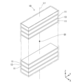
- FIG. 2 is a perspective view showing a schematic example of a laminated magnet.
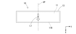
- FIG. 2 is a top view of a laminated magnet.
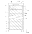
- 3 is a cross-sectional view of the laminated magnet of FIG. 2 cut along a virtual plane.
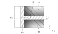
- FIG. 4 is an enlarged view showing a part of FIG. 3 .
- FIG. 2 is a diagram for explaining a method for measuring the first diffusion depth and the second diffusion depth in a plate magnet.
- FIG. 2 is a diagram for explaining a first region and a second region in a specific intermediate magnet.
- FIG. 13 is a diagram for explaining a first region in a specific intermediate magnet.
- FIG. 4 is an enlarged view showing the vicinity of the interface between the plate magnet and the insulating bonding layer.
- FIG. 1 is a perspective view showing another example of a laminated magnet;
- FIG. 13 is a top view of another example 1 of the laminated magnet.
- 11 is a cross-sectional view of the laminated magnet of FIG. 10 cut along a virtual plane.
- FIG. 11 is a diagram for explaining a method for measuring the average orientation degree of a plate magnet in another example 1.
- FIG. 2 is a diagram illustrating each part for measuring an average degree of orientation.
- FIG. 2 is a cross-sectional view illustrating a schematic view of a part of a motor.
- the Z-axis direction in each figure is the stacking direction (first direction) of the laminated magnet 10.
- One direction perpendicular to the Z-axis direction is the X-axis direction (also referred to as the second direction), and the direction perpendicular to the Z-axis direction and the X-axis direction is the Y-axis direction.
- the laminated magnet 10 uses three or more plate magnets 11 containing a rare earth element.
- the plate magnet 11 has an upper bottom surface 11A1, a lower bottom surface 11A2, and a side surface 11B.
- the laminated magnet 10 is formed by alternately stacking the plate magnets 11 and insulating bonding layers 13.
- the first diffusion depth ⁇ m measured by measurement method (1) and the second diffusion depth ⁇ m measured by measurement method (2) for a specific intermediate magnet 112A that is any one of the intermediate magnets 112 excluding the topmost magnet 111 located at the top and the bottommost magnet 113 located at the bottom among the plate magnets 11 are: 0.35 ⁇ / ⁇ 0.50 Meet the following.
- the amount of the heavy rare earth element in the first region R1 satisfying the conditions (3) to (6) is defined as ⁇ % by mass, When the amount of the heavy rare earth element in the second region R2 satisfying the conditions (7) to (8) is ⁇ % by mass, ⁇ / ⁇ 5.0 Meet the following.
- Measurement method (1) A line analysis is performed on a straight line L2 that passes through the center of gravity G2 of the planar figure of the specific intermediate magnet 112A appearing in the cross section and extends in the stacking direction, from the upper bottom surface 11A1 to the center of gravity G2 of the planar figure, to obtain a first profile of the intensity of the heavy rare earth element normalized so that the maximum intensity along that line is 1.
- Measurement method (2) A line analysis is performed on a straight line L3 that passes through the center of gravity G2 of the planar figure of specific intermediate magnet 112A appearing in the cross section and extends in a direction perpendicular to the stacking direction, from side surface 11B to center of gravity G2 of the planar figure, and a second profile of the intensity of the heavy rare earth element is obtained, normalized so that the maximum intensity along that line is 1.
- the distance between the position of side surface 11B and the position where the intensity of the heavy rare earth element first becomes 0.7 is defined as the second diffusion depth ⁇ ⁇ m.
- Condition (3) The first region is present on the specific intermediate magnet side from the interface between the specific intermediate magnet and the insulating bonding layer.
- Condition (4) The first region is a rectangle having a size of 10 ⁇ m in the stacking direction and a size of 50 ⁇ m in a direction perpendicular to the stacking direction.
- Condition (6) The rectangle is in contact with the insulating bonding layer.
- the second region is a rectangle having a size of 10 ⁇ m in the stacking direction and a size of 50 ⁇ m in a direction perpendicular to the stacking direction.
- the plate magnet 11 is a permanent magnet containing a rare earth element. From the viewpoint of having good magnetic properties, the plate magnet 11 is preferably a rare earth sintered magnet.
- the composition of the plate magnet 11 is not particularly limited as long as it contains rare earth elements. From the viewpoint of increasing the magnetic flux density, the total amount of rare earth elements in the plate magnet 11 is preferably 31.0 mass% or less, and preferably 29.5 mass% or less. The lower limit of the total amount of rare earth elements in the plate magnet 11 is, for example, 27 mass% or more, and may be 28 mass% or more, or 28.5 mass% or more.
- the total amount of rare earth elements in the plate magnet 11 can be measured by X-ray fluorescence analysis. The total amount of rare earth elements can be adjusted by changing the content of rare earth elements contained in the raw materials of the plate magnet 11 and the insulating bonding layer 13.
- Examples of the plate magnet 11 include magnets containing rare earth elements (R), transition metal elements (T), and boron (B). Such magnets are also called R-T-B magnets.
- the rare earth element may be, for example, one or more selected from the group consisting of neodymium (Nd), praseodymium (Pr), terbium (Tb), dysprosium (Dy), samarium (Sm), yttrium (Y), scandium (Sc), lanthanum (La), cerium (Ce), europium (Eu), gadolinium (Gd), holmium (Ho), ytterbium (Yb), and lutetium (Lu).
- Nd neodymium
- Pr praseodymium
- Tb terbium
- Dy dysprosium
- Sm samarium
- Y yttrium
- Sc scandium
- La lanthanum
- Ce cerium
- Eu europium
- Gd gadolinium
- Ho holmium
- Yb lutetium
- Lu lutetium
- Nd as the main component means that the content (mass%) of Nd is the highest among the rare earth elements.
- the B content is preferably 0.1% by mass or more and 3% by mass or less of the entire plate magnet 11, and more preferably 0.5% by mass or more and 1.5% by mass or less.
- the transition metal element may be, for example, one or more selected from the group consisting of iron (Fe), cobalt (Co), and nickel (Ni). Among these, from the viewpoint of magnetic properties, it is preferable to include one or more of Fe and Co as the transition metal element, and it is more preferable to include Fe as the main component.
- Fe as the main component means that the content (mass%) of Fe is the highest among the transition metal elements.
- the content of the transition metal element is preferably 60% by mass or more, more preferably 65% by mass or more, of the entire plate magnet 11.
- the upper limit of the transition metal element is not particularly limited, and can be, for example, 73% by mass or less of the entire plate magnet 11.
- a part of Fe may be replaced with Co. For example, when the total of Fe and Co is 100% by mass, the content of Co can be more than 0% by mass and 1% by mass or less.
- the plate magnet 11 may contain elements other than the above elements (hereinafter also referred to as other elements).
- the other elements include at least one selected from the group consisting of aluminum (Al), copper (Cu), zinc (Zn), indium (In), silicon (Si), phosphorus (P), sulfur (S), titanium (Ti), vanadium (V), chromium (Cr), manganese (Mn), nickel (Ni), gallium (Ga), germanium (Ge), zirconium (Zr), niobium (Nb), molybdenum (Mo), palladium (Pd), silver (Ag), cadmium (Cd), tin (Sn), antimony (Sb), hafnium (Hf), tantalum (Ta), and tungsten (W).
- the content of other elements is preferably 0% by mass or more and 3% by mass or less of the entire plate magnet 11 .
- the plate magnet 11 has a region in which the concentration of the heavy rare earth element decreases from at least a part of the surface of the plate magnet 11 toward the inside of the plate magnet 11.
- the decrease in the concentration of the heavy rare earth element is represented by the shade of the hatching. Parts with a high concentration of the heavy rare earth element are shown with a dark shade, while parts with a low concentration are shown with a light shade.
- a configuration having a region in which the concentration of the heavy rare earth element decreases can contribute to reducing the amount of the heavy rare earth element added while maintaining magnetic properties.
- the heavy rare earth element may be one or more selected from the group consisting of terbium (Tb), dysprosium (Dy), gadolinium (Gd), holmium (Ho), europium (Eu), thulium (Tm), ytterbium (Yb), and lutetium (Lu).
- the heavy rare earth element is preferably one or more of Dy and Tb.
- the region in plate magnet 11 where the concentration of the heavy rare earth element is reduced can be formed, for example, by applying a material containing a heavy rare earth element to the surface of plate magnet 11 and then heat treating it. Details will be described later.
- the plate magnet 11 preferably has, for example, a main phase of Nd 2 Fe 14 B and a rare earth rich phase having a higher rare earth element content than the main phase.
- the plate magnet 11 may further have a boron rich phase having a higher boron content than the main phase.
- the main phase usually has a tetragonal crystal structure.
- the above-mentioned Nd 2 Fe 14 B has a tetragonal crystal structure.
- the main phase of the plate magnet 11 can be identified as the component with the largest peak intensity by performing XRD (X-ray diffraction) analysis on the plate magnet 11. That is, when the peak intensity of Nd 2 Fe 14 B is the largest, it can be determined that the plate magnet 11 has a main phase of Nd 2 Fe 14 B.
- the average degree of orientation of the plate magnet 11 is preferably 90% or more, and more preferably 95% or more. The higher the average degree of orientation of the plate magnet 11, the better, but it is usually 99.5% or less.
- the white arrows indicate the orientation direction. Multiple plate magnets 11 can be used, for example, lined up in a direction perpendicular to the orientation direction, as shown in Figure 3.
- the average orientation of the plate magnet 11 is determined, for example, as follows.
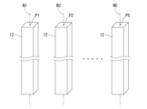
- the plate magnet 11 is a rectangular parallelepiped (rectangular prism) as shown in Figs. 1 and 9, for example, it is cut out to a size corresponding to the measuring device and measured.
- the average orientation degree is obtained as the average orientation degree of each part of 1 mm width centered on the normal line Nn at multiple points Pn from one end to the other end on the long side.
- the number of multiple points Pn is not particularly limited. In Fig. 9, five points P1-P5 and normal lines N1-N5 at each point P1-P5 are shown.
- the number of multiple points Pn may be two, but five or more is preferable.
- the number of multiple points Pn is usually 10 or less.
- a pulse type high magnetic field measuring device magnet field: 4T
- a sample of a size that can fit into the measuring device is cut out from the center of the cut-out part.
- the average orientation is determined as the average orientation degree of each portion of a 1 mm width centered on the normal Nn at multiple points Pn from one end to the other end on the curve C1 on the convex side of the outer periphery of the plate magnet 11 when viewed from the first direction (Z-axis direction).
- the number of multiple points Pn is not particularly limited. When the size of the plate magnet 11 is sufficiently small, the number of multiple points Pn may be two, but five or more is preferable. The number of multiple points Pn is usually 10 or less. Note that when the plate magnet 11 has a convex curved shape, the radius of curvature of the curve C1 is not limited to being constant and may vary.
- points P2-P4 in this embodiment are taken in order from one end at positions that divide the distance between points P1 and P5 at both ends of the curve C1 at equal intervals (positions that divide the distance into four in this embodiment). Note that point P3 in this embodiment is located in the middle of the curve C1.
- each portion 12 is, for example, in the shape of a roughly rectangular prism, as shown in FIG. 14. Note that in reality, the top and bottom surfaces in FIG. 14 are curved surfaces.
- the degree of orientation of each portion 12 is measured, for example, with a pulsed high magnetic field measuring device (magnetic field: 4T). If the cut-out portion does not fit into the measuring device, cut out a sample from the center of the cut-out portion to a size that can fit into the measuring device.
- the average value of the degrees of orientation of each portion 12 is calculated as the average degree of orientation.
- the average degree of orientation of the plate magnet 11 can be controlled, for example, by appropriately designing the magnetic field applied in the orientation process described below. For example, even if the plate magnet 11 has a convex curved shape, the above-mentioned average degree of orientation of 90% or more can be achieved by applying a magnetic field that spreads in the normal direction of the curve C1 of the plate magnet 11 in the orientation process described below.
- the plate magnet 11 has a smaller distance from the surface to the deepest part than a block-shaped magnet that is thicker. Therefore, the plate magnet 11 is suitable for diffusing heavy rare earth elements to the inside when the heavy rare earth elements are diffused through grain boundaries.
- the plate magnet 11 can be preferably used as a laminated magnet in which multiple plate magnets 11 and insulating bonding layers 13 are stacked.
- the laminated magnet 10 in FIG. 1 has multiple plate magnets 11 stacked with the thickness direction of the plate magnet 11 as the stacking direction. In this laminated magnet, the plate magnets 11 and insulating bonding layers 13 are stacked alternately. In a laminated magnet, each plate magnet 11 is sometimes referred to as a magnet body.
- the plate magnet 11 may have a shape other than a rectangle when viewed from above. For example, as shown in Figures 10 and 11, it may have a curved shape (such as a circular arc) that is convex in one direction when viewed from above (the positive direction in the X-axis direction in Figure 11, the upward direction in Figure 11).
- the thickness of the plate magnet 11 is preferably 0.5 mm or more and 4.0 mm or less, and more preferably 1.2 mm or more and 2.5 mm or less. If the thickness of the plate magnet 11 is 0.5 mm or more, it is easy to form the plate magnet 11 while ensuring the average degree of orientation. If the thickness of the plate magnet 11 is 4.0 mm or less, it is easy to diffuse the heavy rare earth element to the inside. Furthermore, if the thickness is 4.0 mm or less, the eddy current loss inside the laminated magnet 10 can be suitably reduced.
- the dimensions of the plate magnet 11 in the direction perpendicular to the thickness are not particularly limited. For example, the plate magnet 11 can be 0.5 mm or more and 4.0 mm or less in thickness, 4 mm or more and 10 mm or less in length, and 10 mm or more and 30 mm or less in width.
- the insulating bonding layer 13 is not particularly limited.
- the insulating bonding layer 13 is preferably mainly composed of inorganic crystals.
- "mainly composed of inorganic crystals” means that the content of inorganic crystals in the insulating bonding layer 13 is 50% by mass or more.
- the content of inorganic crystals in the insulating bonding layer 13 is preferably 80% by mass or more, more preferably 90% by mass or more, and may be 100% by mass.
- composition of the insulating bonding layer 13 can be analyzed by the following method: The presence of inorganic crystals is determined by micro X-ray analysis or XRD analysis, and the content of inorganic crystals is calculated in combination with composition analysis by EPMA (Electron Probe Micro Analyser).
- the insulating bonding layer 13 contains one or more inorganic crystals selected from the group consisting of CaF2, BaF2, SrF2, MgF2, Al2O3, ZrO2, Dy2O3, Tb2O3, Nd2O3, TbF3 , DyF3 , LiF , SiO2 , BN , ZrB2 , Si3N4 , TiB2 , Pr2O3 , and SiC .
- the insulating bonding layer 13 preferably contains at least a fluoride of Group 2A of the periodic table as an inorganic crystal.
- the insulating bonding layer 13 contains at least one or more fluorides of Group 2A of the periodic table selected from the group consisting of CaF 2 , BaF 2 , SrF 2 , and MgF 2 as the fluoride of Group 2A of the periodic table. Of these, it is particularly preferable that the insulating bonding layer 13 contains CaF 2 .
- the insulating bonding layer 13 preferably contains 80 mass % or more of a fluoride of Group 2A of the periodic table as an inorganic crystal, more preferably 90 mass % or more, and even more preferably 95 mass % or more.
- the upper limit of the content of the fluoride of Group 2A of the periodic table is not particularly limited, and may be, for example, 100 mass %.
- the raw material of the insulating bonding layer 13 preferably contains the above-mentioned compound of a heavy rare earth element in addition to the Group 2A fluoride of the periodic table. If the raw material of the insulating bonding layer 13 contains the above-mentioned compound of a heavy rare earth element, the heavy rare earth element can be favorably diffused into the plate magnet 11. The heavy rare earth element contained in the raw material of the insulating bonding layer 13 diffuses into the plate magnet 11 after heat treatment. Therefore, the insulating bonding layer 13 of the obtained laminated magnet 10 contains almost no heavy rare earth element.
- the mass ratio of the fluoride of Group 2A of the periodic table to the compound of the heavy rare earth element in the raw material of the insulating bonding layer 13 can be, for example, 20:80 to 40:60.
- the insulating bonding layer 13 is disposed, for example, as follows.
- the insulating bonding layer 13 may be arranged to cover the entire surface of the plate magnet 11 (see FIG. 3).
- both upper and lower main surfaces 11A and both side surfaces 11B of each plate magnet 11 are covered with the insulating bonding layer 13, and the insulating bonding layer 13 is arranged to cover the entire surface of the plate magnet 11.
- the insulating bonding layer 13 may be arranged to cover a portion of the surface of the plate magnet 11.
- the insulating bonding layer 13 is provided so as to be in direct contact with the plate magnet 11.
- the insulating bonding layer 13 also bonds (adheres) the plate magnets 11, 11 located on both sides.
- Such a laminated magnet 10 can be suitably formed by hot pressing. The conditions for hot pressing will be explained later.
- the insulating bonding layer 13 may be provided along the orientation direction of the magnetic field of each plate magnet 11 (e.g., the X-axis direction in FIG. 3, the direction of the white arrow in FIG. 3), or along a direction intersecting the orientation direction (e.g., the X-axis direction in FIG. 3) (e.g., the Z-axis direction in FIG. 3).
- the insulating bonding layer 13 is provided along the orientation direction of the plate magnet 11 (the X-axis direction in FIG. 15).
- the insulating bonding layer 13 is arranged approximately parallel to the direction in which the magnetic flux generated in the stator 31 passes through the laminated magnet 10 (the X-axis direction in FIG. 15), so that eddy current loss can be effectively reduced.
- the thickness T of the insulating bonding layer 13 is not particularly limited. From the viewpoint of ensuring sufficient insulation, the thickness T of the insulating bonding layer 13 is preferably 5 ⁇ m or more, more preferably 9 ⁇ m or more, and even more preferably 12 ⁇ m or more. From the viewpoint of ensuring magnetic properties, the thickness T of the insulating bonding layer 13 is preferably 30 ⁇ m or less, more preferably 25 ⁇ m or less, and even more preferably 18 ⁇ m or less.
- the thickness T of the insulating bonding layer 13 is preferably 5 ⁇ m or more and 30 ⁇ m or less, more preferably 9 ⁇ m or more and 25 ⁇ m or less, and even more preferably 12 ⁇ m or more and 18 ⁇ m or less.
- the thickness T of the insulating bonding layer 13 is measured, for example, by observing a cross section of the laminated magnet 10 with a SEM (scanning electron microscope) and determining the distance between the plate magnets 11 located on both sides of the insulating bonding layer 13 (see FIG. 4).
- the laminated magnet 10 is cut in a cross section, taken along an imaginary line L1 that passes through the center of gravity G1 of the laminated magnet 10 and extends in the stacking direction, on an imaginary plane that includes the imaginary line L1 so that the cross-sectional area of the laminated magnet 10 is at its smallest, the specific intermediate magnet 112A, which is any one of the intermediate magnets 112 excluding the uppermost magnet 111 located at the top and the lowermost magnet 113 located at the bottom, among the plate magnet 11,
- the first diffusion depth ⁇ ⁇ m measured by the following measurement method (1) and the second diffusion depth ⁇ ⁇ m measured by the following measurement method (2) are 0.35 ⁇ / ⁇ 0.50 Meet the following.
- Measurement method (1) A line analysis is performed on a straight line L2 that passes through the center of gravity G2 of the planar figure of the specific intermediate magnet 112A appearing in the cross section and extends in the stacking direction, from the upper bottom surface 11A1 to the center of gravity G2 of the planar figure, to obtain a first profile of the intensity of the heavy rare earth element normalized so that the maximum intensity along that line is 1.
- the distance between the position of the upper bottom surface 11A1 and the position where the intensity of the heavy rare earth element first becomes 0.7 is defined as the first diffusion depth ⁇ ⁇ m.
- Measurement method (2) A line analysis is performed on a straight line L3 that passes through the center of gravity G2 of the planar figure of specific intermediate magnet 112A appearing in the cross section and extends in a direction perpendicular to the stacking direction, from side surface 11B to center of gravity G2 of the planar figure, and a second profile of the intensity of the heavy rare earth element is obtained, normalized so that the maximum intensity along that line is 1.
- the distance between the position of side surface 11B and the position where the intensity of the heavy rare earth element first becomes 0.7 is defined as the second diffusion depth ⁇ ⁇ m.
- a cross section of the magnet laminate 10 will be specifically described with reference to Fig. 1 to Fig. 3.
- a virtual line L1 that passes through the center of gravity G1 in Fig. 1 and extends in the stacking direction extends in the Z-axis direction.
- a virtual plane VP that cuts the magnet laminate 10 so that its cross-sectional area is the smallest is the XZ plane that includes the virtual line L1, as shown in Fig. 2.
- a cross section of the magnet laminate 10 cut by a plane that includes the virtual line L1 and intersects with the X-axis direction has a larger cross-sectional area than a cross section cut by the XZ plane.
- each plate magnet 11 forms a rectangular planar figure. 10 to 12, the imaginary line L1 also extends in the Z-axis direction.
- the imaginary plane VP is an XZ plane that includes the imaginary line L1.
- a cross section cut along the imaginary plane VP shows multiple cut surfaces of the plate magnet 11, as shown in Fig. 12. Each cut surface of the plate magnet 11 forms a rectangular planar figure.
- the first diffusion depth ⁇ ⁇ m can be measured, for example, by analyzing the line L2 of EPMA.
- a graph is obtained as the first profile, in which the horizontal axis is the distance from the upper bottom surface 11A1 and the vertical axis is the detection intensity of the heavy rare earth element.
- the intensity of the heavy rare earth element is usually maximum near the upper bottom surface 11A1 and tends to decrease as the distance from the upper bottom surface 11A1 increases.
- the profile of the heavy rare earth element with the highest intensity in the measurement method (1) is taken as the first profile.
- the second diffusion depth ⁇ ⁇ m can be measured, for example, by performing line analysis of EPMA on the straight line L3.
- a graph is obtained as the second profile, in which the horizontal axis represents the distance from the side surface 11B and the vertical axis represents the detected intensity of the heavy rare earth element.
- the intensity of the heavy rare earth element is usually maximum near the side surface 11B and tends to decrease as the distance from the side surface 11B increases.
- the profile of the heavy rare earth element with the highest intensity in the measurement method (1) is taken as the second profile.
- the above ⁇ / ⁇ value of 0.50 or less is an indicator that the diffusion depth of the heavy rare earth element from the upper bottom surface 11A1 is sufficiently greater than the diffusion depth of the heavy rare earth element from the side surface 11B.
- the distance from the upper bottom surface 11A1 to the deepest part is smaller than the distance from the side surface 11B to the deepest part. Therefore, by ensuring the diffusion depth of the heavy rare earth element from the upper bottom surface 11A1, a predetermined amount of heavy rare earth element can be sufficiently diffused toward the deepest part of the plate magnet 11.
- the above ⁇ / ⁇ value of 0.35 or more is an indicator that a certain amount of heavy rare earth elements is present between the upper bottom surface 11A1 and the lower bottom surface 11A2. Therefore, if the above ⁇ / ⁇ value is 0.35 or more, the heat resistance of the plate magnet 11 can be sufficiently ensured.
- the first diffusion depth ⁇ ⁇ m is not particularly limited, and is preferably 650 ⁇ m or more and 1000 ⁇ m or less, and more preferably 700 ⁇ m or more and 980 ⁇ m or less.
- the second diffusion depth ⁇ ⁇ m is not particularly limited, and is preferably 200 ⁇ m or more and 600 ⁇ m or less, and more preferably 250 ⁇ m or more and 500 ⁇ m or less.
- the requirement regarding the ratio ⁇ / ⁇ of heavy rare earth elements may be met by calculating the ratio ⁇ / ⁇ of heavy rare earth elements of multiple specific intermediate magnets 112A and finding that at least one of these specific intermediate magnets 112A satisfies the requirement.
- the laminated magnet 10 has the upper bottom surface 11A1 of the specific intermediate magnet 112A covered with an insulating bonding layer 13, and the side surface 11B of the specific intermediate magnet 112A covered with an insulating bonding layer 13.
- heavy rare earth elements are diffused into the plate magnet 11 from the material of the insulating bonding layer 13 applied to the upper bottom surface 11A1 of the specific intermediate magnet 112A and the material of the insulating bonding layer 13 applied to the side surface 11B of the specific intermediate magnet 112A, making it possible to preferably achieve the above-mentioned ⁇ / ⁇ value.
- the value of ⁇ / ⁇ can be controlled, for example, by adjusting the amount of material of the insulating bonding layer 13 applied on the upper bottom surface 11A1 and the amount of material of the insulating bonding layer 13 applied on the side surface 11B.
- the more the amount of material of the insulating bonding layer 13 applied on the side surface 11B the larger the second diffusion depth ⁇ m tends to be.
- the value of ⁇ / ⁇ can be controlled, for example, by adjusting the hot pressing conditions. For example, by increasing the pressure during hot pressing, the first diffusion depth ⁇ m tends to be larger.
- the first diffusion depth ⁇ m tends to be smaller. Also, for example, by increasing the temperature during hot pressing, the first diffusion depth ⁇ m tends to be larger. On the other hand, by decreasing the temperature during hot pressing, the first diffusion depth ⁇ m tends to be smaller. Also, by increasing the pressure time during hot pressing, the first diffusion depth ⁇ m tends to be larger. On the other hand, shortening the pressure time during hot pressing tends to reduce the first diffusion depth ⁇ m.
- the amount of heavy rare earth element in the first region R1 that satisfies the following conditions (3) to (6) is defined as ⁇ mass %, When the amount of the heavy rare earth element in the second region R2 satisfying the following conditions (7) to (8) is ⁇ % by mass, ⁇ / ⁇ 5.0 Meet the following.
- Condition (5) When a straight line L2 is drawn that passes through the center of gravity G2 of the planar figure of the specific intermediate magnet 112A that appears in the cross section and extends in the stacking direction, the center CT1 of the rectangle lies on the straight line L2.
- Condition (6) The rectangle is in contact with the insulating bonding layer 13.
- the specific intermediate magnet 112A in Figure 6 has an upper bottom surface 11A1, a lower bottom surface 11A2, and a side surface 11B.
- An insulating bonding layer 13 is present above the upper bottom surface 11A1, as shown in Figure 7. That is, the upper bottom surface 11A1 of the specific intermediate magnet 112A constitutes an interface I between the specific intermediate magnet 112A and the insulating bonding layer 13.
- the interface I between the specific intermediate magnet 112A and the insulating bonding layer 13 can be identified by image analysis using, for example, EPMA. As shown in FIG. 6, the center of gravity G2 of the plane figure of the specific intermediate magnet 112A is identified.
- the center of gravity G2 of the plane figure of the specific intermediate magnet 112A can be identified as the intersection of the diagonals of the plane figure.
- a straight line L2 is drawn that passes through the center of gravity G2 and extends in the Z-axis direction.
- the rectangles with a center CT1 on the straight line L2 measuring 10 ⁇ m in the Z-axis direction and 50 ⁇ m in the X-axis direction, the rectangle whose upper side is in contact with the insulating bonding layer 13 is identified as the first region R1 (see FIG. 7). Note that the actual interface I has irregularities as shown in FIG.
- the bottom of the irregularities (the point closest to the center of the plate magnet) is the contact point, and the rectangle of 10 ⁇ m in the stacking direction and 50 ⁇ m in the planar direction is defined as R1.
- the lower bottom surface 11A2 of the specific intermediate magnet 112A forms the interface I between the specific intermediate magnet 112A and the insulating bonding layer 13, a rectangle whose lower edge is in contact with the insulating bonding layer 13 may be identified as the first region R1.
- the center of gravity G2 of the planar figure of the specific intermediate magnet 112A is identified. Because the planar figure of the specific intermediate magnet 112A is rectangular, the center of gravity G2 of the planar figure of the specific intermediate magnet 112A can be identified as the intersection of the diagonals of the planar figure. A rectangle 10 ⁇ m in the Z-axis direction by 50 ⁇ m in the X-axis direction, with a center CT2 at the center of gravity G2, is identified as the second region R2.
- the amount ⁇ of the heavy rare earth element and the amount ⁇ of the heavy rare earth element can be calculated, for example, by subjecting a cross section of the magnet laminate 10 to micro X-ray analysis or XRD analysis in combination with an EPMA composition analysis. For example, 10 or more points are measured in each region by point analysis using EPMA, and the average value is taken as the amount of the heavy rare earth element in that region.
- the amount ⁇ of the heavy rare earth element in the first region R1 is not particularly limited, and is preferably 5.5 mass % or more and 7.5 mass % or less.
- the amount ⁇ of the heavy rare earth element in the second region R2 is not particularly limited, and the amount ⁇ of the heavy rare earth element is preferably 0.3 mass % or more and 1.5 mass % or less.
- the requirement regarding the heavy rare earth element ratio ⁇ / ⁇ needs to be satisfied in at least one of the specific intermediate magnets 112A.
- the ratio ⁇ / ⁇ of the heavy rare earth elements described above can be controlled, for example, by adjusting the thickness of the plate magnet 11 and the hot pressing conditions. For example, by increasing the thickness of the plate magnet 11, the ⁇ / ⁇ value tends to increase. On the other hand, by decreasing the thickness of the plate magnet 11, the ⁇ / ⁇ value tends to decrease. For example, by increasing the temperature during hot pressing while shortening the pressure time, the ⁇ / ⁇ value tends to increase. On the other hand, by decreasing the temperature during hot pressing while lengthening the pressure time, the ⁇ / ⁇ value tends to decrease.
- the corner E1 between the upper bottom surface 11A1 and the side surface 11B, or the corner E2 between the lower bottom surface 11A2 and the side surface 11B be the part with the largest amount of heavy rare earth element.
- the plan view of the cross section of the specific intermediate magnet 112A shows two corners E1 between the upper bottom surface 11A1 and the side surface 11B and two corners E2 between the lower bottom surface 11A2 and the side surface 11B, for a total of four corners E1, E1, E2, E2.
- the part with the largest amount of heavy rare earth element may be any of the four corners E1, E1, E2, E2.
- the portion with the maximum amount of heavy rare earth elements can be identified by line analysis of EPMA.
- line analysis is performed along two diagonals of the planar shape of the specific intermediate magnet 112A from the corner E1 of the specific intermediate magnet 112A to the corner E2 opposite the corner E1.
- the maximum amount of the heavy rare earth elements in the four corners E1, E1, E2, and E2 is defined as the "amount of heavy rare earth elements in the corner E1 or E2".
- line analysis is performed along the straight line L2 of the specific intermediate magnet 112A from the upper bottom surface 11A1 to the lower bottom surface 11A2.
- the larger amount of the heavy rare earth elements in the upper bottom surface 11A1 and the lower bottom surface 11A2 is defined as the "amount of heavy rare earth elements in the main surface 11A".
- line analysis is performed between both side surfaces 11B, 11B along the straight line L3 of the specific intermediate magnet 112A.
- the larger of the amounts of heavy rare earth elements in both side surfaces 11B is defined as the "amount of heavy rare earth element in side surface 11B."
- corner E1 or corner E2 is the portion where the amount of heavy rare earth element is maximum. Note that the amount of heavy rare earth element in main surface 11A and the amount of heavy rare earth element in side surface 11B may be larger or equal to each other.
- the amount of heavy rare earth element in main surface 11A is larger than the amount of heavy rare earth element in side surface 11B.
- the requirement regarding the portion with the largest amount of heavy rare earth element needs to be satisfied in at least one of the specific intermediate magnets 112A.
- the portion where the amount of the heavy rare earth element is greatest can be controlled, for example, by adjusting the amount of the material of the insulating bonding layer 13 applied to the upper bottom surface 11A1 and the lower bottom surface 11A2, and the amount of the material of the insulating bonding layer 13 applied to the side surface 11B.
- the magnet stack 10 preferably contains a metal element of Group 2A of the periodic table in the range from the interface I between the plate magnet 11 and the insulating bonding layer 13 to a depth of 10 ⁇ m on the plate magnet 11 side.
- the metal element of Group 2A of the periodic table may be present as a component of a specific metal phase 17A described later in the range from the interface I between the plate magnet 11 and the insulating bonding layer 13 to a depth of 10 ⁇ m on the plate magnet 11 side.
- the metal element of Group 2A of the periodic table may also be present as fluoride particles 14 of the metal element of Group 2A of the periodic table contained in the specific metal phase 17A, as shown in FIG. 8.
- the laminated magnet 10 has fluoride particles of a metal element, such as fluoride particles 14 of a metal element of Group 2A of the periodic table, in contact with a phase 17A containing a heavy rare earth element and two or more metal components (hereinafter also referred to as a specific metal phase 17A).
- the fluoride particles of the metal element are not limited to fluoride particles 14 of a metal element of Group 2A of the periodic table, and may be, for example, fluoride particles of a heavy rare earth element.
- the specific metal phase 17A is an alloy of a heavy rare earth element and two or more metal components.
- the specific metal phase 17A constitutes a surface layer 17 on the surface of the plate magnet 11.
- the thickness of the surface layer 17 is not particularly limited. From the viewpoint of reducing eddy current loss, the thickness of the surface layer 17 is preferably 10 ⁇ m or more, more preferably 15 ⁇ m or more, and even more preferably 25 ⁇ m or more.
- the upper limit of the thickness of the surface layer 17 is not particularly limited, and is usually 40 ⁇ m or less.
- the manner in which the fluoride particles of the metal element contact the specific metal phase 17A is not particularly limited.
- the fluoride particles 14 of the metal element of Group 2A of the periodic table may be contained in the specific metal phase 17A as shown in FIG. 8.
- the fluoride particles of the metal element exposed on the surface of the insulating bonding layer 13 may contact the specific metal phase 17A.
- FIG. 8 is an enlarged schematic view of region R0 of laminated magnet 10 in FIG. 3.
- the top surface 11A1 of plate magnet 11 forms interface I between plate magnet 11 and insulating bonding layer 13.
- Interface I between plate magnet 11 and insulating bonding layer 13 can be identified by image analysis using, for example, EPMA.
- the metal component is, for example, two or more selected from the group consisting of light rare earth elements and metals in Group 2A of the periodic table. Specifically, the metal component is preferably two or more selected from the group consisting of neodymium (Nd), praseodymium (Pr), lanthanum (La), samarium (Sm), calcium (Ca), barium (Ba), and strontium (Sr).
- Nd neodymium
- Pr praseodymium
- La lanthanum
- Sm samarium
- Ca calcium
- Ba barium
- phase 17A containing a heavy rare earth element and two or more metal components the following combinations of components are exemplified.
- the heavy rare earth element is derived from, for example, a compound of a heavy rare earth element contained in the raw material of the insulating bonding layer 13.
- the metallic component Nd is derived from, for example, a main phase of Nd 2 Fe 14 B in the plate magnet 11.
- the metallic component Group 2A metal of the periodic table is derived from, for example, a compound of Group 2A of the periodic table contained in the raw material of the insulating bonding layer 13.
- the reason for this is presumed to be as follows. That is, the lower the total amount of rare earth elements in the plate magnet 11, the less likely Nd-rich components originating from the main phase and components containing Pr will flow to the surface of the plate magnet 11.
- the present inventors have newly discovered that even in a laminated magnet 10 using a plate magnet 11 with a low total amount of rare earth elements (e.g., 31.0 mass% or less), Nd and Pr can be present near the interface I by hot pressing.
- the present disclosure has developed a technology that satisfies the requirements for the interface I between the plate magnet 11 and the insulating bonding layer 13 by using fluoride particles 14 of a metal element of Group 2A of the periodic table and fluoride particles of a heavy rare earth element as the raw material for the insulating bonding layer 13, and by adjusting the hot pressing conditions. For example, by increasing the pressure during hot pressing and lengthening the pressurizing time, it is possible to preferably form a configuration in which fluoride particles of a metal element are in contact with a specific metal phase 17A that contains a heavy rare earth element and two or more metal components.
- each of the above elements can be determined by a combination of X-ray microanalysis and EPMA composition analysis. Furthermore, the formation of an alloy between a heavy rare earth element and two or more metal components can be determined by detecting lattice distortion, etc.
- the requirements for the Group 2A metal elements of the periodic table need only be met in at least one of a number of 50 ⁇ m ⁇ 50 ⁇ m square visual fields observed when the cross-sectional structure of the magnet laminate 10 is observed.
- the average particle size of fluoride particles of metal elements such as fluoride particles 14 of metal elements of Group 2A of the periodic table is not particularly limited.
- the average particle size of the fluoride particles is preferably 2.0 ⁇ m or more and 8.0 ⁇ m or less, more preferably 2.2 ⁇ m or more and 6.0 ⁇ m or less, and even more preferably 2.5 ⁇ m or more and 4.0 ⁇ m or less.
- the insulation resistance is increased and eddy current loss can be reduced.
- the plate magnet 11 and the insulating bonding layer 13 are easily compatible with each other, and the adhesive strength between the plate magnet 11 and the insulating bonding layer 13 can be improved.
- the average particle diameter of the above-mentioned fluoride particles can be determined, for example, by subjecting a cross-section of the laminated magnet 10 to micro X-ray analysis or XRD analysis, performing image analysis using EPMA, and calculating the area-equivalent circle diameter from the particle area of the fluoride particles. Specifically, the average particle diameter is calculated as follows. Focus is placed on a number of fluoride particles that can be observed without missing particles in a given observation field (e.g., 50 ⁇ m ⁇ 50 ⁇ m). The diameter (diameter of an area-equivalent circle) of an ideal circle (true circle) having an area equal to the area (projected area) of each particle image of the fluoride particle 14 is calculated as the particle diameter of each particle. The particle diameters of each particle are then arithmetically averaged to calculate the average particle diameter.
- the average particle size of the fluoride particles can be controlled by adjusting the average particle size of the fluoride particles of the metal element used as the raw material of the insulating bonding layer 13.
- Fine pulverization step, second lubricant addition step The SC alloy powder after the coarse pulverization step is finely pulverized to a predetermined average particle size D50 (fine pulverization step).
- the average particle size D50 can be, for example, 2.0 ⁇ m to 3.5 ⁇ m.
- a lubricant may be added to the finely pulverized SC alloy powder (second lubricant addition step). This step may be carried out, for example, in an inert atmosphere (nitrogen atmosphere, argon atmosphere, etc.).
- Powder filling process, orientation process, molding process The powder of the SC alloy after the pulverization process is filled into a mold. This process may be performed, for example, under an inert atmosphere (nitrogen atmosphere, argon atmosphere, etc.).
- the mold has a plurality of molding spaces of a predetermined thickness. Each molding space is partitioned, for example, by a plurality of partition plates.
- a magnetic field is applied in a predetermined direction to the mold after the powder filling to align the orientation of the SC alloy powder. Then, the powder of the SC alloy filled in the mold is pressed to form a molded body of the SC alloy.
- a molded body of the SC alloy having a predetermined degree of orientation for example, an average degree of orientation of 90% or more
- a predetermined thickness for example, a thickness of 0.5 mm or more and 4.0 mm or less
- Mold Breaking Step First Firing Step
- the molded body is removed from the mold (mold breaking step).
- the molded body is sintered at a predetermined sintering temperature (e.g., 900°C to 1200°C) for a predetermined time (e.g., 2 hours to 5 hours) (first sintering step).
- This sintering is preferably performed in a vacuum. Prior to this sintering, heating at a temperature lower than the sintering temperature may be performed for dehydrogenation.
- the raw material of the insulating bonding layer 13 is coated on the surface of the fired compact.
- the raw material of the insulating bonding layer 13 may be, for example, a mixture of raw powder of inorganic crystal components, compound powder containing a heavy rare earth element, and a solvent.
- the raw material of the insulating bonding layer 13 may be coated on at least one main surface of the compact, or may be coated on both main surfaces.
- the main surface of the compact is the surface corresponding to the main surface 11A of the plate magnet 11.
- the raw material of the insulating bonding layer 13 may be coated on the entire surface of the compact, that is, on both main surfaces and side surfaces when the compact is in a plate shape.
- Laminate Temporarily Fixing Process A predetermined number of molded bodies coated with the raw material of the insulating bonding layer 13 are stacked and temporarily fixed.
- the temporarily fixed laminate of molded bodies is also referred to as a laminate. According to this method, it is possible to manufacture the plate magnet 11 without the process of cutting out plate-shaped magnets from a large magnet by a cutting process or the like.
- the temporarily fixed laminate is placed in a hot press mold, and uniaxial hot pressing is performed.
- This process may be performed, for example, in a vacuum atmosphere (for example, 10 ⁇ 3 Pa to 10 ⁇ 4 Pa) or in an inert atmosphere (for example, a nitrogen atmosphere, an argon atmosphere, etc.).
- the temperature of the hot press may be, for example, 700° C. to 1100° C.
- the pressing time of the hot press may be, for example, 1 second to 1 hour.
- the pressure of the hot press is preferably 3 MPa or more, more preferably 5 MPa or more, and even more preferably 8 MPa or more.
- the upper limit of the pressure of the hot press is not particularly limited, and is, for example, 100 MPa or less.
- the heat treatment time of the hot press may be, for example, 10 minutes to 20 hours.
- the magnet stack 10 is manufactured, which includes the plate magnets 11 and the insulating bonding layers 13.
- the magnet stack 10 is formed by bonding a plurality of plate magnets 11 together via the insulating bonding layers 13, forming an integrated structure.
- the hot pressing process allows the heavy rare earth elements (Tb, Dy, etc.) contained in the raw material of the applied insulating bonding layer 13 to diffuse into the inside of the plate magnet 11.
- the hot pressing process also allows the rare earth components (Nd components) in the plate magnet 11 (e.g., Nd 2 Fe 14 B) to flow out to the surface of the plate magnet 11, forming a surface layer 17 of an Nd-rich phase near the interface I between the plate magnet 11 and the insulating bonding layer 13 (e.g., a layer containing CaF 2 ).
- This hot pressing process also allows the insulating bonding layer 13 to be sufficiently thin, and the thickness of the insulating bonding layer 13 to be uniform.
- the laminated magnet 10 obtained in the above manner can be regarded as a laminated magnet manufactured by hot pressing (hot uniaxial pressing) a laminate having the raw material of the insulating bonding layer 13 sandwiched between at least a pair of plate magnets 11, 11 (sintered bodies of SC alloy) so that pressure is applied in a direction in which the raw material of the insulating bonding layer 13 is crushed.
- the laminated magnet 10 can be understood as a laminated magnet manufactured by arranging a first plate magnet 11 (sintered body of SC alloy), the raw material of the insulating bonding layer 13, and a second plate magnet 11 (sintered body of SC alloy) in this order to form a laminate, and heating the laminate while applying pressure to both sides of the first plate magnet 11 and the second plate magnet 11.
- the raw material of the insulating bonding layer 13 may contain inorganic crystals.
- the raw material of the insulating bonding layer 13 may further contain a component containing a heavy rare earth element.
- the raw material of the insulating bonding layer 13 preferably contains 20% by mass to 40 % by mass of CaF2 and 60% by mass to 80% by mass of TbF3 , where the total of CaF2 and TbF3 is 100% by mass.
- the uses of the magnet laminate 10 are not particularly limited.
- the magnet laminate 10 is suitable as a magnet for a motor.
- the magnet laminate 10 has low eddy current loss generated inside and is not easily deteriorated over time, so it can contribute to one or more of the following effects: miniaturization of the motor, suppression of heat generation, improvement of heat resistance, and improvement of heat dissipation.
- the insulating bonding layer 13 of the magnet laminate 10 is mainly composed of inorganic crystals, the insulating performance is less likely to change due to the influence of humidity, temperature, and deterioration over time, compared to an insulating bonding layer such as a resin. Therefore, the magnet laminate 10 is useful for various applications where it is desired that the insulating performance is not easily changed.
- the motor 30 includes a stator 31 and a rotor 33 arranged inside the stator 31.
- the laminated magnet 10 is arranged on the rotor 33, and a winding (not shown) is arranged on the stator 31.
- the motor 30 in Figure 15 is an inner rotor type with magnets arranged on the inside (rotating shaft side) and windings arranged on the outside.
- the motor is not limited to the inner rotor type.
- the motor may be an outer rotor type with windings arranged on the inside (rotating shaft side) and magnets arranged on the outside.
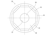
- the rotor 33 comprises a rotating shaft 34, a rotating core 35, and multiple laminated magnets 10.
- the rotating core 35 is formed by laminating electromagnetic steel sheets.
- a shaft hole 37 is formed in the center of the rotating core 35.
- the rotating shaft 34 is inserted into the shaft hole 37.
- a plurality of magnet holes 39 are formed in the rotating core 35 at intervals in the circumferential direction.
- a laminated magnet 10 is inserted into each magnet hole 39.
- the magnet laminate 10 of the present embodiment can efficiently impart heat resistance without using an excessive amount of heavy rare earth elements.
- the reason for this is presumed to be as follows. Note that the present disclosure is not limited to this presumed reason.
- the ideal heavy rare earth diffusion state in plate magnet 11 is considered to be a state in which rare earths (e.g., Nd, Pr, etc.) are substituted with heavy rare earth elements (e.g., Tb, Dy, etc.) only on the surface of the main phase (magnet crystal grains) constituting plate magnet 11.
- rare earths e.g., Nd, Pr, etc.
- heavy rare earth elements e.g., Tb, Dy, etc.
- the magnet laminate 10 of this embodiment satisfies "(4) requirement regarding the diffusion depth ⁇ / ⁇ of the heavy rare earth element" and "(5) requirement regarding the ratio ⁇ / ⁇ of the heavy rare earth element", so that it is possible to realize a configuration close to an ideal heavy rare earth diffusion state of the heavy rare earth element while suppressing the total amount of the heavy rare earth element. Therefore, it is presumed that it is possible to efficiently impart heat resistance without using an excessive amount of the heavy rare earth element. For example, since an excessive amount of the heavy rare earth element is not used, it can contribute to reducing costs and suppressing a decrease in magnetic force.
- corner E1 or corner E2 is the part where the amount of heavy rare earth element is maximum, it can contribute to further improving heat resistance.
- the insulation between the plate magnets 11 can be improved compared to when a metal element from Group 2A of the periodic table is not present. Therefore, a reduction in eddy current loss can be expected.
- the bonding strength between the plate magnet 11 and the insulating bonding layer 13 can be strengthened.
- the insulation between the plate magnets 11 can be suitably improved, and eddy current loss can be further reduced.
- the interface I between the plate magnet 11 and the insulating bonding layer 13 has good compatibility, and the adhesive strength between the plate magnet 11 and the insulating bonding layer 13 can be increased.
- SC alloy preparation process The main raw materials of Nd/Pr alloy, alloy containing Co, Al, Cu, Ga, Zr, and simple metal were mixed to prepare strip cast alloys (SC alloys) (for example, composition: Nd 2 Fe 14 B) in an argon atmosphere.
- SC alloy strip cast alloys
- the SC alloy was a plate-shaped powder, and the dimensions of the main surface were 10 mm x 10 mm to 20 mm x 20 mm.
- the "Rare earth elements" column of "Plate magnet” in Table 1 indicates the rare earth elements contained in the plate magnet.
- each magnet had the thickness shown in Table 1 and was a rectangular parallelepiped with a length x width of 5 mm x 16 mm.
- a magnetic field e.g., 5000 V was applied in the planar direction of each compact (perpendicular to the thickness direction) to align the orientation of the SC alloy powder.
- the SC alloy powder packed into the mold was compressed to form an SC alloy compact.
- the compression molding conditions were: pressure: 5 MPa-20 MPa, packing density: 3.0 g/cm3-4.0 g / cm3 , relative density: 40%-52%.
- Mold disassembly process first firing process
- the outer frame was removed from the mold, and a continuous arrangement of molded bodies and partition plates (material to be fired) was prepared.
- the material to be fired was heated in an Ar atmosphere at 500°C for 3-4 hours.
- the material to be fired was held at 930°C-1050°C for 3 hours and fired in a vacuum atmosphere.
- Insulating bonding layer coating process After the first firing process, the partition plate was removed from the fired object, and the raw material for the insulating bonding layer was coated on six surfaces of the magnet before lamination. A mixture of compound powder 1-3 and a solvent shown in Table 1 was used as the raw material for the insulating bonding layer. The compound powder 1-3 in the raw material for the insulating bonding layer was mixed (mass%) as shown in Table 1 for the compound powder 1-3. The coating thickness of the raw material for the insulating bonding layer was 12 ⁇ m or more and 14 ⁇ m or less. The raw material for the insulating bonding layer was coated in the air by a spray method.
- Laminate Temporary Fixing Process Eight to eighty magnets coated with an insulating adhesive layer were laminated in air and temporarily fixed. The number of magnets laminated was adjusted so that the dimension of the laminated magnet in the lamination direction was 50 mm. This method makes it possible to manufacture plate-shaped magnets without the need for a cutting process or other process to cut out plate-shaped magnets from a large magnet.
- Hot pressing process The temporarily fixed laminate was placed in a hot press mold and subjected to uniaxial hot pressing.
- the hot pressing conditions for each example and comparative example were as shown in Table 1.
- "vac” in “atmosphere” represents vacuum conditions.
- the hot pressing pressure time was 1 second to 1 hour, and the hot pressing heat treatment time was 10 minutes to 20 hours.
- Tables 1 and 2 show the characteristics of each of the Examples and Comparative Examples.
- the column “First diffusion depth: ⁇ " in “Diffusion depth of heavy rare earth element” indicates the first diffusion depth measured by the method described in “(4) Requirement regarding diffusion depth ⁇ / ⁇ of heavy rare earth element” above.
- the column “Second diffusion depth: ⁇ ” indicates the second diffusion depth measured by the method described in “(4) Requirement regarding diffusion depth ⁇ / ⁇ of heavy rare earth element” above.
- the column “Depth ratio: ⁇ / ⁇ ” indicates the value of ⁇ / ⁇ calculated by the method described in “(4) Requirement regarding diffusion depth ⁇ / ⁇ of heavy rare earth element” above.
- the column "First region: ⁇ " in “Amount of heavy rare earth element” indicates the amount of heavy rare earth element in the first region measured by the method described in “(5) Requirement regarding the ratio of heavy rare earth element ⁇ / ⁇ ” above.
- the column “Second region: ⁇ ” indicates the amount of heavy rare earth element in the second region measured by the method described in “(5) Requirement regarding the ratio of heavy rare earth element ⁇ / ⁇ ” above.
- the column “Concentration ratio: ⁇ / ⁇ ” indicates the value of ⁇ / ⁇ calculated by the method described in “(5) Requirement regarding the ratio of heavy rare earth element ⁇ / ⁇ ” above.
- the “high concentration portion” column of “amount of heavy rare earth element” shows the results of measurement using the method described in “(6) Requirements for portion with maximum amount of heavy rare earth element” above.
- “Corner portion” indicates that the amount of heavy rare earth element at corner portion E1 or corner portion E2 is greater than the amount of heavy rare earth element at main surface 11A and the amount of heavy rare earth element at side surface 11B.
- "Main surface” indicates that the amount of heavy rare earth element at main surface 11A is greater than the amount of heavy rare earth element at corner portion E1 or corner portion E2 and the amount of heavy rare earth element at side surface 11B.
- “Side surface” indicates that the amount of heavy rare earth element at side surface 11B is greater than the amount of heavy rare earth element at corner portion E1 or corner portion E2 and the amount of heavy rare earth element at main surface 11A.
- the "Composition” column of "Interface” indicates the elements detected in the range from the interface between the plate magnet and the insulating bonding layer to a depth of 10 ⁇ m on the plate magnet side, as explained in “(7) Requirements for the interface between the plate magnet 11 and the insulating bonding layer 13" above.
- the "Presence of Group 2A Metal Element” column indicates whether the requirement that a Group 2A metal element is present in the range from the interface between the plate magnet and the insulating bonding layer to a depth of 10 ⁇ m on the plate magnet side is met.
- the “Bonding with specific metal phase” column indicates whether the requirement that a fluoride particle of a metal element is in contact with a phase containing a heavy rare earth element and two or more metal components is met.
- “Average particle size” indicates the average particle size of the fluoride particles, measured by the method explained in “(6) Requirements for the average particle size of fluoride particles”.
- Coercivity (kA/m) was measured using a pulse BH tracer. The evaluation direction of the measurement was perpendicular to the surface of the top magnet for the laminated magnet. A high coercivity is an indicator of high heat resistance as a magnet.
- a block magnet of 5 mm x 16 mm x 50 mm was prepared as a reference.
- the block magnet and the laminated magnet of each Example and Comparative Example were attached to a motor, and a test was conducted in which the motor was driven at rotation speeds of 2000 rpm, 4000 rpm, 6000 rpm, and 8000 rpm.
- the surface temperatures of the block magnet and the laminated magnet of each Example and Comparative Example were measured using a laser and a Thermo Label (registered trademark).
- the difference value (°C) was calculated by subtracting the surface temperature (°C) of the laminated magnet of each Example and Comparative Example from the surface temperature (°C) of the block magnet, and the difference value (°C) was evaluated according to the following criteria.
- a low difference value (°C) is an indicator of an advantage in reducing eddy current loss.
- the evaluation was as follows: "A”: The difference value is less than -20°C. "B”: The difference value is between -20°C and -10°C. "C”: The difference value is -10°C or more.
- Example 1-21 satisfies the following requirements (a) to (d).
- Comparative Example 1-5 does not satisfy the following requirements. Comparative Examples 1 and 5 do not satisfy the requirements (c) and (d). Comparative Example 2-4 does not satisfy the requirement (d).
- Example 1-21 the coercive force was evaluated as “A” or "B.” In contrast, in Comparative Example 1-5, the coercive force was evaluated as “C.” Example 1-21 suggests that the heat resistance can be improved efficiently without using an excessive amount of a heavy rare earth element.
- Example 6-21 which further satisfied the following requirement (e), was rated as "A" for coercive force. It was suggested that by satisfying requirement (e), the heat resistance can be further improved.
- Examples 11-21 which further satisfied the following requirement (f), were evaluated as having a strength of "AA" or "A.” It was suggested that by satisfying requirement (f), the adhesive strength between the plate magnet and the insulating bonding layer can be improved.
- Examples 17-21 which further satisfied the following requirement (g), were rated as "AA” for strength and "A” for heat generation temperature. It was suggested that by satisfying requirement (g), it is possible to improve strength and reduce eddy current loss.
Landscapes
- Engineering & Computer Science (AREA)
- Power Engineering (AREA)
- Physics & Mathematics (AREA)
- Electromagnetism (AREA)
- Manufacturing & Machinery (AREA)
- Chemical & Material Sciences (AREA)
- Crystallography & Structural Chemistry (AREA)
- Inorganic Chemistry (AREA)
- Permanent Field Magnets Of Synchronous Machinery (AREA)
- Hard Magnetic Materials (AREA)
- Manufacturing Cores, Coils, And Magnets (AREA)
Abstract
過剰に重希土元素を使用することなく効率よく耐熱性を持たせることが可能な新規な積層磁石を提供する。 積層磁石(10)は、希土類元素を含む板磁石(11)が3以上用いられている。積層磁石(10)は、板磁石(11)と、絶縁接合層(13)と、が交互に積層されている。板磁石(11)のうち、最上位に位置する最上位磁石(111)及び最下位に位置する最下位磁石(113)を除いた中間磁石(112)のいずれかである特定中間磁石(112A)について、測定方法(1)による第1拡散深さαμmと、測定方法(2)による第2拡散深さβμmが、0.35≦β/α≦0.50を満たす。条件(3)~(6)を満たす第1領域(R1)における重希土類元素の量をγ質量%とし、条件(7)~(8)を満たす第2領域(R2)における重希土類元素の量をδ質量%とした場合に、γ/δ≧5.0を満たす。
Description
本開示は、積層磁石及びモーターに関する。
特許文献1は、希土類永久磁石の製造方法を開示する。この希土類永久磁石の製造方法は、希土類元素のフッ化物を含有する粉末を当該焼結磁石体の表面に存在させた状態で、当該焼結磁石体及び粉末を当該焼結磁石体の焼結温度以下の温度で熱処理を施すことにより、当該粉末に含まれていた希土類元素を当該焼結磁石体に吸収させる。
また、複数の希土類磁石を用いた、積層磁石も提案されている(例えば、特許文献2-3)。
また、複数の希土類磁石を用いた、積層磁石も提案されている(例えば、特許文献2-3)。
近年、積層磁石には種々の要求がある。例えば、過剰に重希土元素を使用することなく効率よく耐熱性を持たせることが可能な新規な積層磁石が望まれている。
本開示は、上記実情を鑑みてなされたものであり、過剰に重希土元素を使用することなく効率よく耐熱性を持たせることが可能な新規な積層磁石を提供することを目的とする。本開示は、以下の形態として実現することが可能である。
本開示は、上記実情を鑑みてなされたものであり、過剰に重希土元素を使用することなく効率よく耐熱性を持たせることが可能な新規な積層磁石を提供することを目的とする。本開示は、以下の形態として実現することが可能である。
〔1〕 上底面、下底面、及び側面を有し、希土類元素を含む板磁石が3以上用いられてなり、
前記板磁石と、絶縁接合層と、が交互に積層された積層磁石であって、
前記板磁石のうち、最上位に位置する最上位磁石及び最下位に位置する最下位磁石を除いた中間磁石のいずれかである特定中間磁石について、
前記積層磁石の重心を通り積層方向に延びる仮想直線をとり、前記仮想直線を含む仮想平面で、前記積層磁石の断面積が最も小さくなるように切断した断面を観察した場合に、
以下の測定方法(1)による第1拡散深さαμmと、以下の測定方法(2)による第2拡散深さβμmが、
0.35≦β/α≦0.50
を満たし、
下記条件(3)~(6)を満たす第1領域における重希土類元素の量をγ質量%とし、
下記条件(7)~(8)を満たす第2領域における前記重希土類元素の量をδ質量%とした場合に、
γ/δ≧5.0
を満たす、積層磁石。
測定方法(1):前記断面に現れる前記特定中間磁石の平面図形の重心を通り、かつ前記積層方向に延びる直線上を、前記上底面から平面図形の重心までの間についてライン分析し、その間の最大強度が1となるように規格化した前記重希土類元素の強度の第1プロファイルを得る。前記上底面の位置と、前記重希土類元素の強度がはじめて0.7となる位置との距離を第1拡散深さαμmとする。
測定方法(2):前記断面に現れる前記特定中間磁石の平面図形の重心を通り、かつ前記積層方向と直交する方向に延びる直線上を、前記側面から平面図形の重心までの間についてライン分析し、その間の最大強度が1となるように規格化した前記重希土類元素の強度の第2プロファイルを得る。前記側面の位置と、前記重希土類元素の強度がはじめて0.7となる位置との距離を第2拡散深さβμmとする。
条件(3):前記第1領域は、前記特定中間磁石と前記絶縁接合層との界面から前記特定中間磁石側に存在する。
条件(4):前記第1領域は、前記積層方向に10μm、かつ前記積層方向に直交する方向に50μmの長方形である。
条件(5):前記断面に現れる前記特定中間磁石の平面図形の重心を通り、かつ前記積層方向に延びる直線を引くと、前記長方形の中心は、前記直線上に存在する。
条件(6):前記長方形は、前記絶縁接合層に接している。
条件(7):前記第2領域は、前記積層方向に10μm、かつ前記積層方向に直交する方向に50μmの長方形である。
条件(8):前記長方形の中心は、前記断面に現れる前記特定中間磁石の平面図形の重心に位置する。
前記板磁石と、絶縁接合層と、が交互に積層された積層磁石であって、
前記板磁石のうち、最上位に位置する最上位磁石及び最下位に位置する最下位磁石を除いた中間磁石のいずれかである特定中間磁石について、
前記積層磁石の重心を通り積層方向に延びる仮想直線をとり、前記仮想直線を含む仮想平面で、前記積層磁石の断面積が最も小さくなるように切断した断面を観察した場合に、
以下の測定方法(1)による第1拡散深さαμmと、以下の測定方法(2)による第2拡散深さβμmが、
0.35≦β/α≦0.50
を満たし、
下記条件(3)~(6)を満たす第1領域における重希土類元素の量をγ質量%とし、
下記条件(7)~(8)を満たす第2領域における前記重希土類元素の量をδ質量%とした場合に、
γ/δ≧5.0
を満たす、積層磁石。
測定方法(1):前記断面に現れる前記特定中間磁石の平面図形の重心を通り、かつ前記積層方向に延びる直線上を、前記上底面から平面図形の重心までの間についてライン分析し、その間の最大強度が1となるように規格化した前記重希土類元素の強度の第1プロファイルを得る。前記上底面の位置と、前記重希土類元素の強度がはじめて0.7となる位置との距離を第1拡散深さαμmとする。
測定方法(2):前記断面に現れる前記特定中間磁石の平面図形の重心を通り、かつ前記積層方向と直交する方向に延びる直線上を、前記側面から平面図形の重心までの間についてライン分析し、その間の最大強度が1となるように規格化した前記重希土類元素の強度の第2プロファイルを得る。前記側面の位置と、前記重希土類元素の強度がはじめて0.7となる位置との距離を第2拡散深さβμmとする。
条件(3):前記第1領域は、前記特定中間磁石と前記絶縁接合層との界面から前記特定中間磁石側に存在する。
条件(4):前記第1領域は、前記積層方向に10μm、かつ前記積層方向に直交する方向に50μmの長方形である。
条件(5):前記断面に現れる前記特定中間磁石の平面図形の重心を通り、かつ前記積層方向に延びる直線を引くと、前記長方形の中心は、前記直線上に存在する。
条件(6):前記長方形は、前記絶縁接合層に接している。
条件(7):前記第2領域は、前記積層方向に10μm、かつ前記積層方向に直交する方向に50μmの長方形である。
条件(8):前記長方形の中心は、前記断面に現れる前記特定中間磁石の平面図形の重心に位置する。
本開示によれば、過剰に重希土元素を使用することなく効率よく耐熱性を持たせることが可能な新規な積層磁石を提供できる。
ここで、本開示の望ましい例を示す。
〔2〕 前記特定中間磁石では、前記上底面と前記側面の角部、又は前記下底面と前記側面の角部が、前記重希土類元素の量が最大となる部位となっている、〔1〕に記載の積層磁石。
〔3〕 前記板磁石と前記絶縁接合層との前記界面から前記特定中間磁石側の深さ10μmまでの範囲には、周期表第2A族金属元素が存在している、〔1〕又は〔2〕に記載の積層磁石。
〔4〕 金属元素のフッ化物粒子が、前記重希土類元素と2種以上の金属成分を含む相と接している、〔1〕から〔3〕のいずれかに記載の積層磁石。
〔5〕 前記フッ化物粒子の平均粒子径は、2.0μm以上8.0μm以下である、〔4〕に記載の積層磁石。
〔6〕 〔1〕から〔5〕のいずれかに記載の積層磁石を有する、モーター。
〔2〕 前記特定中間磁石では、前記上底面と前記側面の角部、又は前記下底面と前記側面の角部が、前記重希土類元素の量が最大となる部位となっている、〔1〕に記載の積層磁石。
〔3〕 前記板磁石と前記絶縁接合層との前記界面から前記特定中間磁石側の深さ10μmまでの範囲には、周期表第2A族金属元素が存在している、〔1〕又は〔2〕に記載の積層磁石。
〔4〕 金属元素のフッ化物粒子が、前記重希土類元素と2種以上の金属成分を含む相と接している、〔1〕から〔3〕のいずれかに記載の積層磁石。
〔5〕 前記フッ化物粒子の平均粒子径は、2.0μm以上8.0μm以下である、〔4〕に記載の積層磁石。
〔6〕 〔1〕から〔5〕のいずれかに記載の積層磁石を有する、モーター。
以下、本開示を詳しく説明する。なお、本明細書において、数値範囲について「-」を用いた記載では、特に断りがない限り、下限値及び上限値を含むものとする。例えば、「10-20」という記載では、下限値である「10」、上限値である「20」のいずれも含むものとする。すなわち、「10-20」は、「10以上20以下」と同じ意味である。また、本明細書において、各数値範囲の上限値及び下限値は、任意に組み合わせることができる。以下、各図におけるZ軸方向は、積層磁石10の積層方向(第1の方向)である。Z軸方向と直交する一の方向をX軸方向(第2の方向とも称する)とし、Z軸方向及びX軸方向と直交する方向をY軸方向とする。
1.積層磁石10
図1から図3に示すように、積層磁石10は、希土類元素を含む板磁石11が3以上用いられている。板磁石11は、上底面11A1、下底面11A2、及び側面11Bを有する。積層磁石10は、板磁石11と、絶縁接合層13と、が交互に積層されている。積層磁石10の重心G1を通り積層方向に延びる仮想直線L1をとり、仮想直線L1を含む仮想平面VPで、積層磁石10の断面積が最も小さくなるように切断した断面を観察した場合に、板磁石11のうち、最上位に位置する最上位磁石111及び最下位に位置する最下位磁石113を除いた中間磁石112のいずれかである特定中間磁石112Aについて、測定方法(1)による第1拡散深さαμmと、測定方法(2)による第2拡散深さβμmが、
0.35≦β/α≦0.50
を満たす。
条件(3)~(6)を満たす第1領域R1における重希土類元素の量をγ質量%とし、
条件(7)~(8)を満たす第2領域R2における重希土類元素の量をδ質量%とした場合に、
γ/δ≧5.0
を満たす。
測定方法(1):断面に現れる特定中間磁石112Aの平面図形の重心G2を通り、かつ積層方向に延びる直線L2上を、上底面11A1から平面図形の重心G2までの間についてライン分析し、その間の最大強度が1となるように規格化した重希土類元素の強度の第1プロファイルを得る。上底面11A1の位置と、重希土類元素の強度がはじめて0.7となる位置との距離を第1拡散深さαμmとする。
測定方法(2):断面に現れる特定中間磁石112Aの平面図形の重心G2を通り、かつ積層方向と直交する方向に延びる直線L3上を、側面11Bから平面図形の重心G2までの間についてライン分析し、その間の最大強度が1となるように規格化した前記重希土類元素の強度の第2プロファイルを得る。側面11Bの位置と、重希土類元素の強度がはじめて0.7となる位置との距離を第2拡散深さβμmとする。
条件(3):前記第1領域は、前記特定中間磁石と前記絶縁接合層との界面から前記特定中間磁石側に存在する。
条件(4):前記第1領域は、前記積層方向に10μm、かつ前記積層方向に直交する方向に50μmの長方形である。
条件(5):前記断面に現れる前記特定中間磁石の平面図形の重心を通り、かつ前記積層方向に延びる直線を引くと、前記長方形の中心は、前記直線上に存在する。
条件(6):前記長方形は、前記絶縁接合層に接している。
条件(7):前記第2領域は、前記積層方向に10μm、かつ前記積層方向に直交する方向に50μmの長方形である。
条件(8):前記長方形の中心は、前記断面に現れる前記特定中間磁石の平面図形の重心に位置する。
図1から図3に示すように、積層磁石10は、希土類元素を含む板磁石11が3以上用いられている。板磁石11は、上底面11A1、下底面11A2、及び側面11Bを有する。積層磁石10は、板磁石11と、絶縁接合層13と、が交互に積層されている。積層磁石10の重心G1を通り積層方向に延びる仮想直線L1をとり、仮想直線L1を含む仮想平面VPで、積層磁石10の断面積が最も小さくなるように切断した断面を観察した場合に、板磁石11のうち、最上位に位置する最上位磁石111及び最下位に位置する最下位磁石113を除いた中間磁石112のいずれかである特定中間磁石112Aについて、測定方法(1)による第1拡散深さαμmと、測定方法(2)による第2拡散深さβμmが、
0.35≦β/α≦0.50
を満たす。
条件(3)~(6)を満たす第1領域R1における重希土類元素の量をγ質量%とし、
条件(7)~(8)を満たす第2領域R2における重希土類元素の量をδ質量%とした場合に、
γ/δ≧5.0
を満たす。
測定方法(1):断面に現れる特定中間磁石112Aの平面図形の重心G2を通り、かつ積層方向に延びる直線L2上を、上底面11A1から平面図形の重心G2までの間についてライン分析し、その間の最大強度が1となるように規格化した重希土類元素の強度の第1プロファイルを得る。上底面11A1の位置と、重希土類元素の強度がはじめて0.7となる位置との距離を第1拡散深さαμmとする。
測定方法(2):断面に現れる特定中間磁石112Aの平面図形の重心G2を通り、かつ積層方向と直交する方向に延びる直線L3上を、側面11Bから平面図形の重心G2までの間についてライン分析し、その間の最大強度が1となるように規格化した前記重希土類元素の強度の第2プロファイルを得る。側面11Bの位置と、重希土類元素の強度がはじめて0.7となる位置との距離を第2拡散深さβμmとする。
条件(3):前記第1領域は、前記特定中間磁石と前記絶縁接合層との界面から前記特定中間磁石側に存在する。
条件(4):前記第1領域は、前記積層方向に10μm、かつ前記積層方向に直交する方向に50μmの長方形である。
条件(5):前記断面に現れる前記特定中間磁石の平面図形の重心を通り、かつ前記積層方向に延びる直線を引くと、前記長方形の中心は、前記直線上に存在する。
条件(6):前記長方形は、前記絶縁接合層に接している。
条件(7):前記第2領域は、前記積層方向に10μm、かつ前記積層方向に直交する方向に50μmの長方形である。
条件(8):前記長方形の中心は、前記断面に現れる前記特定中間磁石の平面図形の重心に位置する。
(1)板磁石11
板磁石11は、希土類元素を含む永久磁石である。板磁石11は、良好な磁気特性を有する観点から、希土類焼結磁石が好ましい。
板磁石11は、希土類元素を含む永久磁石である。板磁石11は、良好な磁気特性を有する観点から、希土類焼結磁石が好ましい。
板磁石11の組成は、希土類元素を含む限り特に限定されない。板磁石11の総希土類元素量は、磁束密度を高くする観点から、31.0質量%以下であることが好ましく、29.5質量%以下であることが好ましい。板磁石11の総希土類元素量の下限値は、例えば、27質量%以上であり、28質量%以上、28.5質量%以上であってもよい。板磁石11の総希土類元素量は、蛍光X線分析によって測定できる。総希土類元素量は、板磁石11や絶縁接合層13の原料に 含まれる希土類元素の含有量を変えることにより調整できる。
板磁石11としては、例えば希土類元素(R)、遷移金属元素(T)、及びホウ素(B)を含む磁石が挙げられる。このような磁石は、R-T-B系の磁石とも称される。
希土類元素は、例えば、ネオジム(Nd)、プラセオジウム(Pr)、テルビウム(Tb)、ジスプロシウム(Dy)、サマリウム(Sm)、イットリウム(Y)、スカンジウム(Sc)、ランタン(La)、セリウム(Ce)、ユーロピウム(Eu)、ガドリニウム(Gd)、ホルミウム(Ho)、イッテルビウム(Yb)、及びルテチウム(Lu)からなる群より選ばれる1種以上が挙げられる。これらの中でも、希土類元素として、Nd、Pr、Dy、及びTbの1種以上を含むことが好ましく、Ndを主成分として含むことがより好ましい。なお、Ndを主成分とするとは、希土類元素においてNdの含有量(質量%)が最も多いことを表す。
Bの含有量は、板磁石11全体の0.1質量%以上3質量%以下が好ましく、0.5質量%以上1.5質量%以下がより好ましい。
Bの含有量は、板磁石11全体の0.1質量%以上3質量%以下が好ましく、0.5質量%以上1.5質量%以下がより好ましい。
遷移金属元素は、例えば、鉄(Fe)、コバルト(Co)、及びニッケル(Ni)からなる群より選ばれる1種以上が挙げられる。これらの中でも、磁気特性の観点から、遷移金属元素として、Fe及びCoの1種以上を含むことが好ましく、Feを主成分として含むことがより好ましい。なお、Feを主成分とするとは、遷移金属元素においてFeの含有量(質量%)が最も多いことを表す。
遷移金属元素の含有量は、板磁石11全体の60質量%以上が好ましく、65質量%以上がより好ましい。遷移金属元素の上限値は特に限定されず、例えば、板磁石11全体の73質量%以下とすることができる。また、Fe及びCoを含む場合において、Feの一部がCoで置換されていてもよい。例えば、FeとCoの合計を100質量%とした場合のCoの含有量は、0質量%より多く1質量%以下とすることができる。
遷移金属元素の含有量は、板磁石11全体の60質量%以上が好ましく、65質量%以上がより好ましい。遷移金属元素の上限値は特に限定されず、例えば、板磁石11全体の73質量%以下とすることができる。また、Fe及びCoを含む場合において、Feの一部がCoで置換されていてもよい。例えば、FeとCoの合計を100質量%とした場合のCoの含有量は、0質量%より多く1質量%以下とすることができる。
板磁石11は、上記の元素以外の元素(以下、その他の元素とも称する)を含んでいてもよい。その他の元素としては、アルミニウム(Al)、銅(Cu)、亜鉛(Zn)、インジウム(In)、ケイ素(Si)、リン(P)、硫黄(S)、チタン(Ti)、バナジウム(V)、クロム(Cr)、マンガン(Mn)、ニッケル(Ni)、ガリウム(Ga)、ゲルマニウム(Ge)、ジルコニウム(Zr)、ニオブ(Nb)、モリブデン(Mo)、パラジウム(Pd)、銀(Ag)、カドミウム(Cd)、スズ(Sn)、アンチモン(Sb)、ハフニウム(Hf)、タンタル(Ta)、タングステン(W)からなる群より選ばれる1種以上が挙げられる。
その他の元素の含有量は、板磁石11全体の0質量%以上3質量%以下が好ましい。
その他の元素の含有量は、板磁石11全体の0質量%以上3質量%以下が好ましい。
板磁石11は、保磁力を向上させる観点から、板磁石11の表面の少なくとも一部から板磁石11内部に向かって、重希土類元素の濃度が減少する領域を有することがより好ましい。図4においては、重希土類元素の濃度減少を網掛けの濃淡で表している。重希土類元素の濃度が高い部位は、濃い網掛けで示され、他方、濃度が低い部位は、薄い網掛けで示されている。重希土類元素の濃度が減少する領域を有する構成によれば、磁気特性を確保しつつ、重希土類元素の添加量低減に寄与できる。重希土類元素は、テルビウム(Tb)、ジスプロシウム(Dy)、ガドリニウム(Gd)、ホルミウム(Ho)、ユーロピウム(Eu)、ツリウム(Tm)、イッテルビウム(Yb)、及びルテチウム(Lu)からなる群より選ばれる1種以上が挙げられる。これらの中でも上記の重希土類元素は、Dy及びTbの1種以上であることが好ましい。
なお、板磁石11における重希土類元素の濃度が減少する領域は、例えば、板磁石11の表面に重希土類元素を含む原料を塗布し、熱処理して形成できる。詳細については、後に説明する。
なお、板磁石11における重希土類元素の濃度が減少する領域は、例えば、板磁石11の表面に重希土類元素を含む原料を塗布し、熱処理して形成できる。詳細については、後に説明する。
板磁石11は、例えば、Nd2Fe14Bの主相と、主相よりも希土類元素の含有量が多い希土類リッチ相と、を有していることが好ましい。板磁石11は、主相よりもホウ素の含有量が多いホウ素リッチ相を更に有していてもよい。主相は、通常、正方晶系の結晶構造を有している。例えば上述のNd2Fe14Bは、正方晶系の結晶構造を有している。
なお、板磁石11の主相は、板磁石11をXRD(X-ray diffraction)分析して、ピーク強度が最も大きい成分として特定できる。すなわち、Nd2Fe14Bのピーク強度が最も大きい場合に、板磁石11がNd2Fe14Bの主相を有すると判別できる。
なお、板磁石11の主相は、板磁石11をXRD(X-ray diffraction)分析して、ピーク強度が最も大きい成分として特定できる。すなわち、Nd2Fe14Bのピーク強度が最も大きい場合に、板磁石11がNd2Fe14Bの主相を有すると判別できる。
板磁石11の平均配向度は、90%以上であることが好ましく、95%以上であることがより好ましい。板磁石11の平均配向度は、高ければ高いほど良いが、通常99.5%以下である。なお、図2及び図3において、白抜き矢印は配向方向を表す。複数の板磁石11は、例えば、図3に示すように配向方向と直交する方向に並べて用いることができる。
板磁石11の平均配向度は、例えば次のようにして求める。
板磁石11が、例えば図1,9に示されるように、直方体状(四角柱状)の場合には、測定器に対応するサイズに切り出して測定する。例えば、図9の板磁石11の長方形状の底面において、長辺上の一端から他端の複数の点Pnにおける法線Nnを中心とした1mm幅の各部分の平均配向度として求める。複数の点Pnの数は、特に限定されない。図9において、5つの点P1-P5と、各点P1-P5における法線N1-N5が示される。板磁石11のサイズが十分に小さい場合には、複数の点Pnの数は、2つでもよいが、5つ以上が好ましい。複数の点Pnの数は、通常10以下である。測定器としては、例えば、パルス式高磁界測定器(磁場:4T)を用いることができる。切り出した部分が測定器に入らない場合には、切り出した部分の中央部において測定器に入るサイズのサンプルを切り出す。
板磁石11が、例えば図1,9に示されるように、直方体状(四角柱状)の場合には、測定器に対応するサイズに切り出して測定する。例えば、図9の板磁石11の長方形状の底面において、長辺上の一端から他端の複数の点Pnにおける法線Nnを中心とした1mm幅の各部分の平均配向度として求める。複数の点Pnの数は、特に限定されない。図9において、5つの点P1-P5と、各点P1-P5における法線N1-N5が示される。板磁石11のサイズが十分に小さい場合には、複数の点Pnの数は、2つでもよいが、5つ以上が好ましい。複数の点Pnの数は、通常10以下である。測定器としては、例えば、パルス式高磁界測定器(磁場:4T)を用いることができる。切り出した部分が測定器に入らない場合には、切り出した部分の中央部において測定器に入るサイズのサンプルを切り出す。
板磁石11が、例えば図10,13に示されるように、凸の曲形状である場合には、第1の方向(Z軸方向)から見た板磁石11の外周のうち、凸側の曲線C1上の一端から他端の複数の点Pnにおける法線Nnを中心とした1mm幅の各部分の平均配向度として求める。複数の点Pnの数は、特に限定されない。板磁石11のサイズが十分に小さい場合には、複数の点Pnの数は、2つでもよいが、5つ以上が好ましい。複数の点Pnの数は、通常10以下である。なお、板磁石11が凸の曲形状である場合において、曲線C1の曲率半径は一定に限られず、変化してもよい。
以下、板磁石11が凸の曲形状である場合の平均配向度の算出方法について図13,14を参照しつつ具体的に説明する。Z軸方向から見た板磁石11の外周のうち、凸側の曲線を曲線C1とし、曲線C1と対向する辺を辿る線を対向線C2とする。
まず、図13に示すように、複数の点Pnを特定する。本実施形態では5つの点P1-P5を特定する。板磁石11において、凸側の曲線C1の一端(例えば左端)から5mm以内の位置と、他端(例えば右端)から5mm以内の位置に両端部の点P1,P5をとる。曲線C1における両端部の点P1,P5までの間を等間隔に分ける位置(本実施形態では4等分する位置)に、一端側から順に複数の点(本実施形態では点P2-P4)をとる。なお、本実施形態の点P3は、曲線C1の真ん中に位置する。
まず、図13に示すように、複数の点Pnを特定する。本実施形態では5つの点P1-P5を特定する。板磁石11において、凸側の曲線C1の一端(例えば左端)から5mm以内の位置と、他端(例えば右端)から5mm以内の位置に両端部の点P1,P5をとる。曲線C1における両端部の点P1,P5までの間を等間隔に分ける位置(本実施形態では4等分する位置)に、一端側から順に複数の点(本実施形態では点P2-P4)をとる。なお、本実施形態の点P3は、曲線C1の真ん中に位置する。
曲線C1において、各点P1-P5における法線N1-N5を特定する。板磁石11から、法線Nnを中心とした1mm幅の部分12を切り出す。各部分12は、例えば、図14に示すように、略四角柱状となる。なお、実際には、図14の上底面は湾曲した面である。各部分12の配向度は、例えば、パルス式高磁界測定器(磁場:4T)によりそれぞれ測定する。切り出した部分が測定器に入らない場合には、切り出した部分の中央部において測定器に入るサイズのサンプルを切り出す。各部分12の配向度の平均値を平均配向度として算出する。
なお、板磁石11の平均配向度は、例えば、後述の配向工程において、印加する磁場を適宜設計することで、コントロールできる。例えば、板磁石11が凸の曲形状である場合であっても、後述の配向工程において、板磁石11の曲線C1の法線方向に拡がる磁場を印加することで、上記の平均配向度90%以上を実現できる。
板磁石11は、より厚みが大きいブロック状の磁石に比して、表面から最深部までの距離が小さい。よって、板磁石11は、重希土類元素を粒界拡散させた場合に、重希土類元素を内部まで拡散させ易く好適である。板磁石11であれば、複数の板磁石11と絶縁接合層13が積層された積層磁石として好適に用いることができる。図1の積層磁石10は、板磁石11の厚み方向を積層方向として、複数の板磁石11が積層されている。この積層磁石は、板磁石11と絶縁接合層13が交互に積層されている。積層磁石では、各板磁石11は、磁石素体とも称されることがある。なお、図1及び図2の板磁石11は、上方(Z軸方向)から見て矩形状をなしている。板磁石11は、上方から見て矩形状以外の形状であってもよく、例えば、図10及び図11のように、上方からみて一の方向(図11のX軸方向における正方向、図11では上方向)に凸の曲形状(いわゆる円弧状等)であってもよい。
板磁石11の厚みは、好ましくは0.5mm以上4.0mm以下であり、より好ましくは1.2mm以上2.5mm以下である。板磁石11の厚みが0.5mm以上であれば、平均配向度を確保しつつ、板磁石11を形成し易い。板磁石11の厚みが4.0mm以下であれば、重希土類元素を内部まで拡散させ易い。また、厚みが4.0mm以下であれば、積層磁石10内部の渦電流損失を好適に低減できる。板磁石11における厚みと直交する方向の寸法は特に限定されない。例えば、板磁石11は、厚み0.5mm以上4.0mm以下、縦4mm以上10mm以下、横10mm以上30mm以下とすることができる。
(2)絶縁接合層13
絶縁接合層13は、特に限定されない。絶縁接合層13は、好ましくは無機結晶を主成分とする。なお、無機結晶を主成分とするとは、絶縁接合層13において無機結晶の含有量が50質量%以上であることを表す。なお、絶縁接合層13において無機結晶の含有量は、80質量%以上であることが好ましく、90質量%以上であることがより好ましく、100質量%であってもよい。
なお、絶縁接合層13の組成は以下の手法で分析できる。無機結晶の存在は微小X線分析又はXRD分析により求め、EPMA(Electron Probe Micro Analyser)の組成分析と組み合わせて無機結晶の含有量を算出する。
絶縁接合層13は、特に限定されない。絶縁接合層13は、好ましくは無機結晶を主成分とする。なお、無機結晶を主成分とするとは、絶縁接合層13において無機結晶の含有量が50質量%以上であることを表す。なお、絶縁接合層13において無機結晶の含有量は、80質量%以上であることが好ましく、90質量%以上であることがより好ましく、100質量%であってもよい。
なお、絶縁接合層13の組成は以下の手法で分析できる。無機結晶の存在は微小X線分析又はXRD分析により求め、EPMA(Electron Probe Micro Analyser)の組成分析と組み合わせて無機結晶の含有量を算出する。
絶縁接合層13は、渦電流損失低減の観点から、無機結晶としてCaF2、BaF2、SrF2、MgF2、Al2O3、ZrO2、Dy2O3、Tb2O3、Nd2O3、TbF3、DyF3、LiF、SiO2、BN、ZrB2、Si3N4、TiB2、Pr2O3、及びSiCからなる群より選ばれる1種以上を含むことが好ましい。
絶縁接合層13は、渦電流損失低減の観点から、無機結晶として、周期表第2A族フッ化物を少なくとも含むことが好ましい。絶縁接合層13は、周期表第2A族フッ化物として、CaF2、BaF2、SrF2、及びMgF2からなる群より選ばれる1種以上を少なくとも含むことがより好ましい。絶縁接合層13は、これらの中でも、CaF2を含むことが特に好ましい。
絶縁接合層13は、無機結晶全体を100質量%とした場合に、無機結晶としての周期表第2A族フッ化物を80質量%以上含むことが好ましく、90質量%以上含むことがより好ましく、95質量%以上含むことが更に好ましい。上記の周期表第2A族フッ化物の含有量の上限値は特に限定されず、例えば100質量%であってもよい。
絶縁接合層13は、渦電流損失低減の観点から、無機結晶として、周期表第2A族フッ化物を少なくとも含むことが好ましい。絶縁接合層13は、周期表第2A族フッ化物として、CaF2、BaF2、SrF2、及びMgF2からなる群より選ばれる1種以上を少なくとも含むことがより好ましい。絶縁接合層13は、これらの中でも、CaF2を含むことが特に好ましい。
絶縁接合層13は、無機結晶全体を100質量%とした場合に、無機結晶としての周期表第2A族フッ化物を80質量%以上含むことが好ましく、90質量%以上含むことがより好ましく、95質量%以上含むことが更に好ましい。上記の周期表第2A族フッ化物の含有量の上限値は特に限定されず、例えば100質量%であってもよい。
絶縁接合層13が、周期表第2A族フッ化物を主成分とする場合において、絶縁接合層13の原料には、周期表第2A族フッ化物とともに、上記の重希土類元素の化合物が含まれていることが好ましい。絶縁接合層13の原料に、上記の重希土類元素の化合物が含まれていれば、板磁石11に重希土類元素を好適に拡散させ得る。なお、絶縁接合層13の原料に含まれる重希土類元素は、熱処理を経て、板磁石11内に拡散する。このため、得られた積層磁石10の絶縁接合層13には、重希土類元素はほぼ含まれていない。
絶縁接合層13の原料における周期表第2A族フッ化物と、重希土類元素の化合物との質量比は、特に限定されない。絶縁接合層13の原料における周期表第2A族フッ化物と、重希土類元素の化合物との質量比は、例えば、20:80-40:60とすることができる。
絶縁接合層13の原料における周期表第2A族フッ化物と、重希土類元素の化合物との質量比は、特に限定されない。絶縁接合層13の原料における周期表第2A族フッ化物と、重希土類元素の化合物との質量比は、例えば、20:80-40:60とすることができる。
絶縁接合層13の配置は、例えば次のようにされている。
絶縁接合層13は、板磁石11の表面の全体を覆う形態で配置されていてもよい(図3参照)。図3の例では、いずれの板磁石11も、上下両方の主面11A及び両側の側面11Bが絶縁接合層13で覆われており、絶縁接合層13は、板磁石11の表面の全体を覆う形態で配置されている。絶縁接合層13は、板磁石11の表面の一部を覆う形態で配置されていてもよい。
絶縁接合層13は、板磁石11の表面の全体を覆う形態で配置されていてもよい(図3参照)。図3の例では、いずれの板磁石11も、上下両方の主面11A及び両側の側面11Bが絶縁接合層13で覆われており、絶縁接合層13は、板磁石11の表面の全体を覆う形態で配置されている。絶縁接合層13は、板磁石11の表面の一部を覆う形態で配置されていてもよい。
絶縁接合層13は、板磁石11に直接接触するようにして設けられている。また、絶縁接合層13は、両側に位置する板磁石11,11を接合(接着)する。このような積層磁石10は、ホットプレスによって好適に形成できる。なお、ホットプレスの条件等については後に説明する。
絶縁接合層13は、各板磁石11の磁場の配向方向(例えば図3のX軸方向、図3の白抜き矢印の方向)に沿って設けられていてもよく、配向方向(例えば図3のX軸方向)と交差する方向(例えば、図3のZ軸方向)に沿って設けられていてもよい。なお、図15に示すように、積層磁石10がモーター用磁石等として用いられる場合には、渦電流損失を効率よく低減する観点から、絶縁接合層13は、板磁石11の配向方向(図15のX軸方向)に沿って設けられていることが好ましい。このような構成によれば、ステーター31で生じた磁束が積層磁石10を通過する方向(図15のX軸方向)に対して絶縁接合層13が略平行に配置されるから、効果的に渦電流損失を低減できる。
絶縁接合層13の厚みTは特に限定されない。絶縁接合層13の厚みTは、絶縁性を十分に確保する観点から、好ましくは5μm以上であり、より好ましくは9μm以上であり、更に好ましくは12μm以上である。絶縁接合層13の厚みTは、磁気特性を確保する観点から、好ましくは30μm以下であり、より好ましくは25μm以下であり、更に好ましくは18μm以下である。これらの観点から、絶縁接合層13の厚みTは、好ましくは5μm以上30μm以下であり、より好ましくは9μm以上25μm以下であり、更に好ましくは12μm以上18μm以下である。
なお、絶縁接合層13の厚みTは、例えば、積層磁石10の断面をSEM(走査電子顕微鏡)で観察し、絶縁接合層13の両側に位置する板磁石11の間の距離として測定する(図4参照)。
なお、絶縁接合層13の厚みTは、例えば、積層磁石10の断面をSEM(走査電子顕微鏡)で観察し、絶縁接合層13の両側に位置する板磁石11の間の距離として測定する(図4参照)。
(3)積層磁石10の構成
板磁石11は、渦電流損失低減の観点から、第1の方向について積層磁石10の寸法50mm当たり10個以上用いられていることが好ましく、20個以上用いられていることが好ましく、25個以上用いられていることが好ましい。上記の磁石の数の上限値は特に限定されず、例えば、42個以下であってもよい。
板磁石11は、渦電流損失低減の観点から、第1の方向について積層磁石10の寸法50mm当たり10個以上用いられていることが好ましく、20個以上用いられていることが好ましく、25個以上用いられていることが好ましい。上記の磁石の数の上限値は特に限定されず、例えば、42個以下であってもよい。
(4)重希土類元素の拡散深さβ/αに関する要件
積層磁石10は、積層磁石10の重心G1を通り積層方向に延びる仮想直線L1をとり、仮想直線L1を含む仮想平面で、積層磁石10の断面積が最も小さくなるように切断した断面を観察した場合に、板磁石11のうち、最上位に位置する最上位磁石111及び最下位に位置する最下位磁石113を除いた中間磁石112のいずれかである特定中間磁石112Aについて、
以下の測定方法(1)による第1拡散深さαμmと、以下の測定方法(2)による第2拡散深さβμmが、
0.35≦β/α≦0.50
を満たす。
測定方法(1):断面に現れる特定中間磁石112Aの平面図形の重心G2を通り、かつ積層方向に延びる直線L2上を、上底面11A1から平面図形の重心G2までの間についてライン分析し、その間の最大強度が1となるように規格化した重希土類元素の強度の第1プロファイルを得る。上底面11A1の位置と、重希土類元素の強度がはじめて0.7となる位置との距離を第1拡散深さαμmとする。
測定方法(2):断面に現れる特定中間磁石112Aの平面図形の重心G2を通り、かつ積層方向と直交する方向に延びる直線L3上を、側面11Bから平面図形の重心G2までの間についてライン分析し、その間の最大強度が1となるように規格化した前記重希土類元素の強度の第2プロファイルを得る。側面11Bの位置と、重希土類元素の強度がはじめて0.7となる位置との距離を第2拡散深さβμmとする。
積層磁石10は、積層磁石10の重心G1を通り積層方向に延びる仮想直線L1をとり、仮想直線L1を含む仮想平面で、積層磁石10の断面積が最も小さくなるように切断した断面を観察した場合に、板磁石11のうち、最上位に位置する最上位磁石111及び最下位に位置する最下位磁石113を除いた中間磁石112のいずれかである特定中間磁石112Aについて、
以下の測定方法(1)による第1拡散深さαμmと、以下の測定方法(2)による第2拡散深さβμmが、
0.35≦β/α≦0.50
を満たす。
測定方法(1):断面に現れる特定中間磁石112Aの平面図形の重心G2を通り、かつ積層方向に延びる直線L2上を、上底面11A1から平面図形の重心G2までの間についてライン分析し、その間の最大強度が1となるように規格化した重希土類元素の強度の第1プロファイルを得る。上底面11A1の位置と、重希土類元素の強度がはじめて0.7となる位置との距離を第1拡散深さαμmとする。
測定方法(2):断面に現れる特定中間磁石112Aの平面図形の重心G2を通り、かつ積層方向と直交する方向に延びる直線L3上を、側面11Bから平面図形の重心G2までの間についてライン分析し、その間の最大強度が1となるように規格化した前記重希土類元素の強度の第2プロファイルを得る。側面11Bの位置と、重希土類元素の強度がはじめて0.7となる位置との距離を第2拡散深さβμmとする。
図1から図3を参照して、積層磁石10を切断した断面について具体的に説明する。積層磁石10において、図1の重心G1を通り積層方向に延びる仮想直線L1は、Z軸方向に延びている。積層磁石10の断面積が最も小さくなるように切断する仮想平面VPは、図2に示すように、仮想直線L1を含むXZ平面である。なお、仮想直線L1を含みX軸方向と交わる平面で切断した断面は、XZ平面で切断した断面よりも積層磁石10の断面積が大きい。仮想平面VPで切断した断面には、図3に示すように、板磁石11の切断面が複数表れる。各板磁石11の切断面は長方形の平面図形をなしている。
図10から図12の積層磁石10についても、仮想直線L1はZ軸方向に延びている。仮想平面VPは、仮想直線L1を含むXZ平面である。仮想平面VPで切断した断面には、図12に示すように、板磁石11の切断面が複数表れる。板磁石11の各切断面は長方形の平面図形をなしている。
図10から図12の積層磁石10についても、仮想直線L1はZ軸方向に延びている。仮想平面VPは、仮想直線L1を含むXZ平面である。仮想平面VPで切断した断面には、図12に示すように、板磁石11の切断面が複数表れる。板磁石11の各切断面は長方形の平面図形をなしている。
図5を参照して、第1拡散深さαμm及び第2拡散深さβμmの測定方法について説明する。第1拡散深さαμmは、例えば、直線L2上をEPMAのラインを分析して測定できる。測定方法(1)では、第1プロファイルとして、横軸が上底面11A1からの距離であり、縦軸が重希土類元素の検出強度であるグラフが得られる。重希土類元素の強度は、通常、上底面11A1近傍で最大強度となり、上底面11A1からの距離が大きくなるにつれて小さくなる傾向を示す。測定方法(1)のライン分析によって重希土類元素が複数種検出される場合には、測定方法(1)において最も強度が高い重希土類元素のプロファイルを第1プロファイルとする。
第2拡散深さβμmは、例えば、直線L3上をEPMAのライン分析をして測定できる。測定方法(2)では、第2プロファイルとして、横軸が側面11Bからの距離であり、縦軸が重希土類元素の検出強度であるグラフが得られる。重希土類元素の強度は、通常、側面11B近傍で最大強度となり、側面11Bからの距離が大きくなるにつれて小さくなる傾向を示す。測定方法(2)のライン分析によって重希土類元素が複数種検出される場合には、測定方法(1)において最も強度が高い重希土類元素のプロファイルを第2プロファイルとする。
第2拡散深さβμmは、例えば、直線L3上をEPMAのライン分析をして測定できる。測定方法(2)では、第2プロファイルとして、横軸が側面11Bからの距離であり、縦軸が重希土類元素の検出強度であるグラフが得られる。重希土類元素の強度は、通常、側面11B近傍で最大強度となり、側面11Bからの距離が大きくなるにつれて小さくなる傾向を示す。測定方法(2)のライン分析によって重希土類元素が複数種検出される場合には、測定方法(1)において最も強度が高い重希土類元素のプロファイルを第2プロファイルとする。
上記のβ/αの値が0.50以下であることは、上底面11A1からの重希土類元素の拡散深さが、側面11Bからの重希土類元素の拡散深さよりも十分に大きいことの一つの指標となる。板磁石11において、上底面11A1から最深部までの距離は、側面11Bから最深部までの距離よりも小さい。よって、上底面11A1からの重希土類元素の拡散深さを確保することで、所定量の重希土元素を板磁石11の最深部に向けて十分に拡散させることができる。
上記のβ/αの値が0.35以上であることは、上底面11A1と下底面11A2との中間にも、ある程度重希土元素が存在していることの一つの指標となる。よって、上記のβ/αの値が0.35以上であれば、板磁石11の耐熱性を十分に確保できる。
上記のβ/αの値が0.35以上であることは、上底面11A1と下底面11A2との中間にも、ある程度重希土元素が存在していることの一つの指標となる。よって、上記のβ/αの値が0.35以上であれば、板磁石11の耐熱性を十分に確保できる。
上記の第1拡散深さαμmは、特に限定されない。上記の第1拡散深さαμmは、好ましくは650μm以上1000μm以下であり、より好ましくは700μm以上980μm以下である。
上記の第2拡散深さβμmは、特に限定されない。上記の第2拡散深さβμmは、好ましくは200μm以上600μm以下であり、より好ましくは250μm以上500μm以下である。
なお、重希土類元素の割合β/αに関する要件は、複数の特定中間磁石112Aの重希土類元素の割合β/αを算出して、そのうちの少なくとも1つの特定中間磁石112Aにおいて満たしていればよい。
上記の第2拡散深さβμmは、特に限定されない。上記の第2拡散深さβμmは、好ましくは200μm以上600μm以下であり、より好ましくは250μm以上500μm以下である。
なお、重希土類元素の割合β/αに関する要件は、複数の特定中間磁石112Aの重希土類元素の割合β/αを算出して、そのうちの少なくとも1つの特定中間磁石112Aにおいて満たしていればよい。
なお、積層磁石10は、特定中間磁石112Aの上底面11A1が絶縁接合層13で覆われるとともに、特定中間磁石112Aの側面11Bが絶縁接合層13で覆われていることが好ましい。このような構成によれば、特定中間磁石112Aの上底面11A1に塗布された絶縁接合層13の材料と、特定中間磁石112Aの側面11Bに塗布された絶縁接合層13の材料から板磁石11に重希土類元素を拡散させ、好適に上記のβ/α値を実現できる。
β/αの値は、例えば、上底面11A1における絶縁接合層13の材料の塗布量と、側面11Bにおける絶縁接合層13の材料の塗布量を調整して、コントロールできる。上底面11A1における絶縁接合層13の材料の塗布量が多い程、第1拡散深さαμmが大きくなる傾向にある。側面11Bにおける絶縁接合層13の材料の塗布量が多い程、第2拡散深さβμmが大きくなる傾向にある。さらに、β/αの値は、例えば、ホットプレス条件を調整して、コントロールできる。例えば、ホットプレス時の圧力を大きくすることで、第1拡散深さαμmが大きくなる傾向にある。他方、ホットプレス時の圧力を小さくすることで、第1拡散深さαμmが小さくなる傾向にある。また、例えば、ホットプレス時の温度を高くすることで、第1拡散深さαμmが大きくなる傾向にある。他方、ホットプレス時の温度を低くすることで、第1拡散深さαμmが小さくなる傾向にある。また、ホットプレス時の加圧時間を長くすることで、第1拡散深さαμmが大きくなる傾向にある。他方、ホットプレス時の加圧時間を短くすることで、第1拡散深さαμmが小さくなる傾向にある。
(5)重希土類元素の割合γ/δに関する要件
下記条件(3)~(6)を満たす第1領域R1における重希土類元素の量をγ質量%とし、
下記条件(7)~(8)を満たす第2領域R2における前記重希土類元素の量をδ質量%とした場合に、
γ/δ≧5.0
を満たす。
条件(3):第1領域R1は、特定中間磁石112Aと絶縁接合層13との界面Iから特定中間磁石112A側に存在する。
条件(4):第1領域R1は、積層方向に10μm、かつ積層方向に直交する方向に50μmの長方形である。
条件(5):断面に現れる特定中間磁石112Aの平面図形の重心G2を通り、かつ積層方向に延びる直線L2を引くと、長方形の中心CT1は、直線L2上に存在する。
条件(6):長方形は、絶縁接合層13に接している。
条件(7):第2領域R2は、積層方向に10μm、かつ積層方向に直交する方向に50μmの長方形である。
条件(8):長方形の中心CT2は、断面に現れる特定中間磁石112Aの平面図形の重心G2に位置する。
下記条件(3)~(6)を満たす第1領域R1における重希土類元素の量をγ質量%とし、
下記条件(7)~(8)を満たす第2領域R2における前記重希土類元素の量をδ質量%とした場合に、
γ/δ≧5.0
を満たす。
条件(3):第1領域R1は、特定中間磁石112Aと絶縁接合層13との界面Iから特定中間磁石112A側に存在する。
条件(4):第1領域R1は、積層方向に10μm、かつ積層方向に直交する方向に50μmの長方形である。
条件(5):断面に現れる特定中間磁石112Aの平面図形の重心G2を通り、かつ積層方向に延びる直線L2を引くと、長方形の中心CT1は、直線L2上に存在する。
条件(6):長方形は、絶縁接合層13に接している。
条件(7):第2領域R2は、積層方向に10μm、かつ積層方向に直交する方向に50μmの長方形である。
条件(8):長方形の中心CT2は、断面に現れる特定中間磁石112Aの平面図形の重心G2に位置する。
図6及び図7を参照して、第1領域R1の特定方法について具体的に説明する。図6の特定中間磁石112Aは上底面11A1、下底面11A2、及び側面11Bを有している。上底面11A1の上側には、図7に示すように絶縁接合層13が存在している。すなわち、特定中間磁石112Aの上底面11A1が、特定中間磁石112Aと絶縁接合層13との界面Iを構成している。特定中間磁石112Aと絶縁接合層13との界面Iは、例えば、EPMAを用いた画像解析にて特定できる。
図6に示すように、特定中間磁石112Aの平面図形の重心G2を特定する。特定中間磁石112Aの平面図形は長方形であるから、特定中間磁石112Aの平面図形の重心G2は、平面図形の対角線の交点として特定できる。重心G2を通りZ軸方向に延びる直線L2を引く。中心CT1が直線L2上に存在するZ軸方向に10μm×X軸方向に50μmの長方形のうち、上辺が絶縁接合層13に接している長方形を第1領域R1として特定する(図7参照)。なお、実際の界面Iには図8のように凹凸があるが、凹凸の最下部(最も板磁石の中心側の点)を接点とし、積層方向に10μmかつ平面方向に50μmの長方形をR1とする。
なお、特定中間磁石112Aの下底面11A2が、特定中間磁石112Aと絶縁接合層13との界面Iを構成している場合において、下辺が絶縁接合層13に接している長方形を第1領域R1として特定してもよい。
図6に示すように、特定中間磁石112Aの平面図形の重心G2を特定する。特定中間磁石112Aの平面図形は長方形であるから、特定中間磁石112Aの平面図形の重心G2は、平面図形の対角線の交点として特定できる。重心G2を通りZ軸方向に延びる直線L2を引く。中心CT1が直線L2上に存在するZ軸方向に10μm×X軸方向に50μmの長方形のうち、上辺が絶縁接合層13に接している長方形を第1領域R1として特定する(図7参照)。なお、実際の界面Iには図8のように凹凸があるが、凹凸の最下部(最も板磁石の中心側の点)を接点とし、積層方向に10μmかつ平面方向に50μmの長方形をR1とする。
なお、特定中間磁石112Aの下底面11A2が、特定中間磁石112Aと絶縁接合層13との界面Iを構成している場合において、下辺が絶縁接合層13に接している長方形を第1領域R1として特定してもよい。
図6を参照して、第2領域R2の特定方法について具体的に説明する。図6に示すように、特定中間磁石112Aの平面図形の重心G2を特定する。特定中間磁石112Aの平面図形は長方形であるから、特定中間磁石112Aの平面図形の重心G2は、平面図形の対角線の交点として特定できる。重心G2に中心CT2が存在するZ軸方向に10μm×X軸方向に50μmの長方形を、第2領域R2として特定する。
重希土類元素の量γと、重希土類元素の量δは、例えば、積層磁石10の断面を微小X線分析又はXRD分析して、EPMAの組成分析と組み合わせて算出できる。例えば、EPMAの点分析で各領域を10点以上測定し、その平均値を当該領域の重希土類元素の量とする。
第1領域R1における重希土類元素の量γは、特に限定されない。重希土類元素の量γは、好ましくは5.5質量%以上7.5質量%以下である。
第2領域R2における重希土類元素の量δは、特に限定されない。重希土類元素の量βは、好ましくは0.3質量%以上1.5質量%以下である。
なお、重希土類元素の割合γ/δに関する要件は、上記の特定中間磁石112Aが複数存在する場合において、そのうちの少なくとも1つの特定中間磁石112Aにおいて満たしていればよい。
第1領域R1における重希土類元素の量γは、特に限定されない。重希土類元素の量γは、好ましくは5.5質量%以上7.5質量%以下である。
第2領域R2における重希土類元素の量δは、特に限定されない。重希土類元素の量βは、好ましくは0.3質量%以上1.5質量%以下である。
なお、重希土類元素の割合γ/δに関する要件は、上記の特定中間磁石112Aが複数存在する場合において、そのうちの少なくとも1つの特定中間磁石112Aにおいて満たしていればよい。
上記の重希土類元素の割合γ/δは、例えば、板磁石11の厚みや、ホットプレス条件を調整して、コントロールできる。例えば、板磁石11の厚みを大きくすることで、γ/δ値が大きくなる傾向にある。他方、板磁石11の厚みを小さくすることで、γ/δ値が小さくなる傾向にある。例えば、ホットプレス時の温度を高くしつつ加圧時間を短くすることで、γ/δ値が大きくなる傾向にある。他方、ホットプレス時の温度を低くしつつ加圧時間を長くすることで、γ/δ値が小さくなる傾向にある。
(6)重希土類元素の量が最大となる部位に関する要件
特定中間磁石112Aでは、耐熱性向上の観点から、上底面11A1と側面11Bの角部E1、又は下底面11A2と側面11Bの角部E2が、重希土類元素の量が最大となる部位となっていることが好ましい。特定中間磁石112Aの断面の平面図形には、図5に示すように、上底面11A1と側面11Bの角部E1が2つと、下底面11A2と側面11Bの角部E2が2つの計4つの角部E1、角部E1、角部E2、角部E2が表れる。重希土類元素の量が最大となる部位は、4つの角部E1、角部E1、角部E2、角部E2のうち、いずれの角部であってもよい。
特定中間磁石112Aでは、耐熱性向上の観点から、上底面11A1と側面11Bの角部E1、又は下底面11A2と側面11Bの角部E2が、重希土類元素の量が最大となる部位となっていることが好ましい。特定中間磁石112Aの断面の平面図形には、図5に示すように、上底面11A1と側面11Bの角部E1が2つと、下底面11A2と側面11Bの角部E2が2つの計4つの角部E1、角部E1、角部E2、角部E2が表れる。重希土類元素の量が最大となる部位は、4つの角部E1、角部E1、角部E2、角部E2のうち、いずれの角部であってもよい。
重希土類元素の量が最大となる部位は、EPMAのライン分析によって特定できる。例えば、特定中間磁石112Aの平面図形の2つの対角線に沿って、特定中間磁石112Aの角部E1から、角部E1と対向する角部E2までライン分析を行う。4つの角部E1、角部E1、角部E2、角部E2の重希土類元素の量のうち、最大の量を「角部E1又は角部E2の重希土類元素の量」とする。また、特定中間磁石112Aの直線L2に沿って、上底面11A1から下底面11A2までライン分析を行う。上底面11A1の重希土類元素の量及び下底面11A2の重希土類元素の量のうち、大きい方の量を「主面11Aの重希土類元素の量」とする。さらに、特定中間磁石112Aの直線L3に沿って、両側面11B,11B間のライン分析を行う。両側面11Bの重希土類元素の量のうち、大きい方の量を「側面11Bの重希土類元素の量」とする。角部E1又は角部E2の重希土類元素の量が、主面11Aの重希土類元素の量及び側面11Bの重希土類元素の量よりも大きい場合に、角部E1又は角部E2が、重希土類元素の量が最大となる部位となっていると判断できる。なお、主面11Aの重希土類元素の量と側面11Bの重希土類元素の量はいずれが大きくてもよく、同等であってもよい。重希土類元素の拡散深さβ/αに関する要件を満たすうえで、主面11Aの重希土類元素の量が、側面11Bの重希土類元素の量よりも大きいとよい。
なお、重希土類元素の量が最大となる部位に関する要件は、上記の特定中間磁石112Aが複数存在する場合において、そのうちの少なくとも1つの特定中間磁石112Aにおいて満たしていればよい。
なお、重希土類元素の量が最大となる部位に関する要件は、上記の特定中間磁石112Aが複数存在する場合において、そのうちの少なくとも1つの特定中間磁石112Aにおいて満たしていればよい。
上記の重希土類元素の量が最大となる部位は、例えば、上底面11A1及び下底面11A2における絶縁接合層13の材料の塗布量と、側面11Bにおける絶縁接合層13の材料の塗布量を調整して、コントロールできる。
(7)板磁石11と絶縁接合層13との界面Iに関する要件
積層磁石10は、絶縁性向上の観点から、板磁石11と絶縁接合層13との界面Iから板磁石11側の深さ10μmまでの範囲に、周期表第2A族金属元素が存在していることが好ましい。周期表第2A族金属元素は、板磁石11と絶縁接合層13との界面Iから板磁石11側の深さ10μmまでの範囲において、後述する特定の金属相17Aの成分として存在し得る。また、周期表第2A族金属元素は、図8に示すように、特定の金属相17Aに含まれる周期表第2A族金属元素のフッ化物粒子14として存在していてもよい。
積層磁石10は、絶縁性向上の観点から、板磁石11と絶縁接合層13との界面Iから板磁石11側の深さ10μmまでの範囲に、周期表第2A族金属元素が存在していることが好ましい。周期表第2A族金属元素は、板磁石11と絶縁接合層13との界面Iから板磁石11側の深さ10μmまでの範囲において、後述する特定の金属相17Aの成分として存在し得る。また、周期表第2A族金属元素は、図8に示すように、特定の金属相17Aに含まれる周期表第2A族金属元素のフッ化物粒子14として存在していてもよい。
また、積層磁石10は、結合強度向上の観点から、周期表第2A族金属元素のフッ化物粒子14等の金属元素のフッ化物粒子が、重希土類元素と2種以上の金属成分を含む相17A(以下、特定の金属相17Aとも称する)と接していることも好ましい。金属元素のフッ化物粒子は、周期表第2A族金属元素のフッ化物粒子14に限定されず、例えば、重希土類元素のフッ化物粒子等であってもよい。特定の金属相17Aは、結合強度をより一層向上する観点から、重希土類元素と2種以上の金属成分が合金を形成していることがより好ましい。特定の金属相17Aは、例えば、板磁石11の表面において表面層17を構成している。表面層17の厚みは特に限定されない。表面層17の厚みは、渦電流損失低減の観点から、好ましくは10μm以上であり、より好ましくは15μm以上であり、更に好ましくは25μm以上である。表面層17の厚みの上限値は特に限定されず、通常40μm以下である。金属元素のフッ化物粒子が、特定の金属相17Aと接する態様は特に限定されない。例えば、周期表第2A族金属元素のフッ化物粒子14は、図8に示すように、特定の金属相17A内に含まれていてよい。それ以外にも、絶縁接合層13の表面に露出した金属元素のフッ化物粒子が、特定の金属相17Aと接していてもよい。
図8は、図3の積層磁石10の領域R0を拡大して模式的に示す拡大図である。板磁石11の上底面11A1は、板磁石11と絶縁接合層13との界面Iを構成している。板磁石11と絶縁接合層13との界面Iは、例えば、EPMAを用いた画像解析にて特定できる。
金属成分は、例えば、軽希土類元素及び周期表第2A族金属からなる群より選ばれる2種以上である。具体的には、金属成分は、ネオジム(Nd)、プラセオジウム(Pr)、ランタン(La)、サマリウム(Sm)、Ca(カルシウム)、Ba(バリウム)、及びSr(ストロンチウム)からなる群より選ばれる2種以上であることが好ましい。
重希土類元素と2種以上の金属成分を含む相17Aとしては、以下の成分の組み合わせを含む相が例示される。
・Tb、Pr、及びNdの組み合わせ
・Tb、La、及びNdの組み合わせ
・Tb、Pr、La、及びNdの組み合わせ
・Tb、Sm、Nd、及びCaの組み合わせ
・Tb、Pr、Nd、及びCaの組み合わせ
・Tb、Dy、Pr、Nd、及びBaの組み合わせ
・Tb、La、Pr、Nd、及びSrの組み合わせ
・Tb、La、Nd、及びCaの組み合わせ
・Tb、Pr、及びNdの組み合わせ
・Tb、La、及びNdの組み合わせ
・Tb、Pr、La、及びNdの組み合わせ
・Tb、Sm、Nd、及びCaの組み合わせ
・Tb、Pr、Nd、及びCaの組み合わせ
・Tb、Dy、Pr、Nd、及びBaの組み合わせ
・Tb、La、Pr、Nd、及びSrの組み合わせ
・Tb、La、Nd、及びCaの組み合わせ
上記の重希土類元素は、例えば、絶縁接合層13の原料に含まれる重希土類元素の化合物に由来する。また、金属成分のNdは、例えば、板磁石11におけるNd2Fe14Bの主相に由来する。金属成分の周期表第2A族金属は、例えば、絶縁接合層13の原料に含まれる周期表第2A族の化合物に由来する。
一般的には、板磁石11の総希土類元素量が低い程、板磁石11由来のNd、Prが板磁石11と絶縁接合層13との界面I付近に存在しにくい傾向にある。この理由は、以下のように推測される。すなわち、板磁石11の総希土類元素量が低い程、主相に由来するNd豊富な成分や、Prを含む成分が、板磁石11の表面に流出しにくくなるためと推測される。本願発明者らは、総希土類元素量が低い(例えば31.0質量%以下)板磁石11を用いた積層磁石10であっても、ホットプレスによってNd、Prを界面I付近に存在させ得ることを新たに見出した。さらに、絶縁接合層13の原料に、周期表第2A族金属元素のフッ化物粒子14及び重希土類元素のフッ化物粒子を用いるとともに、ホットプレスの条件を調整することによって、板磁石11と絶縁接合層13との界面Iに関する要件を充足する本開示の技術を開発した。例えば、ホットプレス時の圧力を大きくしつつ、加圧時間を長くすることで、金属元素のフッ化物粒子が、重希土類元素と2種以上の金属成分を含む特定の金属相17Aと接している構成を好適に形成できる。
上記の各元素の有無は、微小X線分析とEPMAの組成分析と組み合わせて判断できる。また、重希土類元素と2種以上の金属成分が合金を形成していることは、格子ひずみ等を検出することにより判断できる。
なお、周期表第2A族金属元素に関する要件は、積層磁石10の断面構造を観察した際に、50μm×50μmの正方形の視野を複数観察して、そのうちの少なくとも1つの視野において満たしていればよい。
なお、周期表第2A族金属元素に関する要件は、積層磁石10の断面構造を観察した際に、50μm×50μmの正方形の視野を複数観察して、そのうちの少なくとも1つの視野において満たしていればよい。
(8)フッ化物粒子の平均粒子径に関する要件
周期表第2A族金属元素のフッ化物粒子14等の金属元素のフッ化物粒子の平均粒子径は、特に限定されない。フッ化物粒子の平均粒子径は、好ましくは2.0μm以上8.0μm以下であり、より好ましくは2.2μm以上6.0μm以下であり、更に好ましくは2.5μm以上4.0μm以下である。フッ化物粒子の平均粒子径が上記の範囲内であると、絶縁抵抗が高くなり渦電流損失を低減できる。また、フッ化物粒子の平均粒子径が上記の範囲内であると、板磁石11と絶縁接合層13とがなじみやすく、板磁石11と絶縁接合層13の密着強度を向上できる。
周期表第2A族金属元素のフッ化物粒子14等の金属元素のフッ化物粒子の平均粒子径は、特に限定されない。フッ化物粒子の平均粒子径は、好ましくは2.0μm以上8.0μm以下であり、より好ましくは2.2μm以上6.0μm以下であり、更に好ましくは2.5μm以上4.0μm以下である。フッ化物粒子の平均粒子径が上記の範囲内であると、絶縁抵抗が高くなり渦電流損失を低減できる。また、フッ化物粒子の平均粒子径が上記の範囲内であると、板磁石11と絶縁接合層13とがなじみやすく、板磁石11と絶縁接合層13の密着強度を向上できる。
上記のフッ化物粒子の平均粒子径は、例えば、積層磁石10の断面を微小X線分析又はXRD分析して、EPMAを用いた画像解析を行い、フッ化物粒子の粒子面積から面積円相当径を算出することにより求めることができる。
具体的には、次のようにして平均粒子径を求める。所定の観察視野(例えば、50μm×50μm)において、欠けることなく観察できる複数のフッ化物粒子に着目する。フッ化物粒子14の各々の粒子画像の面積(投影面積)と等しい面積を有する理想円(真円)の直径(面積円相当径)を各粒子の粒子径として算出する。そして、各粒子の粒子径を算術平均することにより、平均粒子径を求める。
具体的には、次のようにして平均粒子径を求める。所定の観察視野(例えば、50μm×50μm)において、欠けることなく観察できる複数のフッ化物粒子に着目する。フッ化物粒子14の各々の粒子画像の面積(投影面積)と等しい面積を有する理想円(真円)の直径(面積円相当径)を各粒子の粒子径として算出する。そして、各粒子の粒子径を算術平均することにより、平均粒子径を求める。
なお、フッ化物粒子の平均粒子径は、絶縁接合層13の原料として使用する金属元素のフッ化物粒子の平均粒径を調整して、コントロールできる。
2.積層磁石10の製造方法
積層磁石10の製造方法は特に限定されない。積層磁石10として、板磁石11と絶縁接合層13が交互に積層された積層磁石の製造方法の一例を以下に示す。
積層磁石10の製造方法は特に限定されない。積層磁石10として、板磁石11と絶縁接合層13が交互に積層された積層磁石の製造方法の一例を以下に示す。
(1)SC合金準備工程
希土類元素、遷移金属元素、及びホウ素等を含む原料合金(ストリップキャスト合金(SC合金))を準備する。
希土類元素、遷移金属元素、及びホウ素等を含む原料合金(ストリップキャスト合金(SC合金))を準備する。
(2)水素解砕工程
水素雰囲気下で、所定の温度(例えば200度)、所定の時間(例えば1時間-5時間)で、SC合金に水素を吸わせて、SC合金の粒界(Ndリッチ相)を脆化させる。
水素雰囲気下で、所定の温度(例えば200度)、所定の時間(例えば1時間-5時間)で、SC合金に水素を吸わせて、SC合金の粒界(Ndリッチ相)を脆化させる。
(3)粗粉砕工程、第1の潤滑剤添加工程
水素解砕工程を経たSC合金の粉末を粗粉砕する(粗粉砕工程)。この際、SC合金の粉末に潤滑剤を添加するとよい(第1の潤滑剤添加工程)。この工程は、例えば不活性雰囲気(窒素雰囲気、アルゴン雰囲気等)下で行うとよい。
水素解砕工程を経たSC合金の粉末を粗粉砕する(粗粉砕工程)。この際、SC合金の粉末に潤滑剤を添加するとよい(第1の潤滑剤添加工程)。この工程は、例えば不活性雰囲気(窒素雰囲気、アルゴン雰囲気等)下で行うとよい。
(4)微粉砕工程、第2の潤滑剤添加工程
粗粉砕工程後のSC合金の粉末を、所定の平均粒径D50に微粉砕する(微粉砕工程)。平均粒径D50は、例えば、2.0μm-3.5μmとすることができる。この際、微粉砕した粉末の流動性を良くするために、微粉砕後のSC合金の粉末に潤滑剤を添加してもよい(第2の潤滑剤添加工程)。この工程は、例えば不活性雰囲気(窒素雰囲気、アルゴン雰囲気等)下で行うとよい。
粗粉砕工程後のSC合金の粉末を、所定の平均粒径D50に微粉砕する(微粉砕工程)。平均粒径D50は、例えば、2.0μm-3.5μmとすることができる。この際、微粉砕した粉末の流動性を良くするために、微粉砕後のSC合金の粉末に潤滑剤を添加してもよい(第2の潤滑剤添加工程)。この工程は、例えば不活性雰囲気(窒素雰囲気、アルゴン雰囲気等)下で行うとよい。
(5)粉末充填工程、配向工程、成形工程
微粉砕工程後のSC合金の粉末を、成形型に充填する。この工程は、例えば不活性雰囲気(窒素雰囲気、アルゴン雰囲気等)下で行うとよい。成形型としては、所定の厚みの成形スペースを複数有するものを用いる。各成形スペースは、例えば複数の仕切り板によって仕切られている。粉末充填後の成形型に対して、所定の方向で磁界を印加してSC合金の粉末の配向性を揃える。その後、成形型に充填されたSC合金の粉末を加圧して、SC合金の成形体を成形する。このようにすれば、切断工程を行うことなく、所定の配向度(例えば、平均配向度90%以上)を有し、所定の厚み(例えば、厚み0.5mm以上4.0mm以下)を有する、SC合金の成形体を得ることができる。
微粉砕工程後のSC合金の粉末を、成形型に充填する。この工程は、例えば不活性雰囲気(窒素雰囲気、アルゴン雰囲気等)下で行うとよい。成形型としては、所定の厚みの成形スペースを複数有するものを用いる。各成形スペースは、例えば複数の仕切り板によって仕切られている。粉末充填後の成形型に対して、所定の方向で磁界を印加してSC合金の粉末の配向性を揃える。その後、成形型に充填されたSC合金の粉末を加圧して、SC合金の成形体を成形する。このようにすれば、切断工程を行うことなく、所定の配向度(例えば、平均配向度90%以上)を有し、所定の厚み(例えば、厚み0.5mm以上4.0mm以下)を有する、SC合金の成形体を得ることができる。
(6)型ばらし工程、第1の焼成工程
成形型から成形体を取り出す(型ばらし工程)。成形体を所定の焼成温度(例えば900℃-1200℃)で、所定の時間(例えば2時間-5時間)焼成する(第1の焼成工程)。この焼成は、真空中で行うとよい。この焼成に先立って、脱水素のために、焼成温度よりも低い温度での加熱を行ってもよい。
成形型から成形体を取り出す(型ばらし工程)。成形体を所定の焼成温度(例えば900℃-1200℃)で、所定の時間(例えば2時間-5時間)焼成する(第1の焼成工程)。この焼成は、真空中で行うとよい。この焼成に先立って、脱水素のために、焼成温度よりも低い温度での加熱を行ってもよい。
(7)絶縁接合層塗布工程
焼成した成形体の表面に絶縁接合層13の原料を塗布する。絶縁接合層13の原料は、例えば、無機結晶成分の原料粉末と、重希土類元素を含む化合物粉末と、溶媒の混合物を用いることができる。絶縁接合層13の原料は、成形体における少なくとも一の主面に塗布するとよく、両主面に塗布してもよい。成形体の主面とは、板磁石11の主面11Aに対応する面である。絶縁接合層13の原料は、成形体の全面、すなわち成形体が板状をなす場合には両主面及び側面に塗布してもよい。
焼成した成形体の表面に絶縁接合層13の原料を塗布する。絶縁接合層13の原料は、例えば、無機結晶成分の原料粉末と、重希土類元素を含む化合物粉末と、溶媒の混合物を用いることができる。絶縁接合層13の原料は、成形体における少なくとも一の主面に塗布するとよく、両主面に塗布してもよい。成形体の主面とは、板磁石11の主面11Aに対応する面である。絶縁接合層13の原料は、成形体の全面、すなわち成形体が板状をなす場合には両主面及び側面に塗布してもよい。
(8)積層体仮止め工程
絶縁接合層13の原料が塗布された成形体を、所定の枚数積層し、仮止めする。以下、仮止めされた成形体の積層物を積層体とも称する。本方法によれば、大きな磁石から切断工程等により板状の磁石を切り出す加工無しで板磁石11を製造することが可能である。
絶縁接合層13の原料が塗布された成形体を、所定の枚数積層し、仮止めする。以下、仮止めされた成形体の積層物を積層体とも称する。本方法によれば、大きな磁石から切断工程等により板状の磁石を切り出す加工無しで板磁石11を製造することが可能である。
(9)ホットプレス工程
仮止めした積層体をホットプレス型に入れ、一軸加圧のホットプレスを行う。この工程は、例えば、真空雰囲気下(例えば10-3Pa-10-4Pa)、又は、不活性雰囲気下(窒素雰囲気下、アルゴン雰囲気下等)で行うとよい。ホットプレスの温度は、例えば、700℃-1100℃とすることができる。ホットプレスの加圧時間は、例えば、1秒-1時間とすることができる。ホットプレスの圧力は、好ましくは3MPa以上であり、より好ましくは5MPa以上であり、更に好ましくは8MPa以上である。ホットプレスの圧力の上限値は特に限定されず、例えば100MPa以下である。ホットプレスの熱処理時間は、例えば、10分-20時間とすることができる。
以上の一連の工程により、板磁石11と絶縁接合層13を備えた積層磁石10が製造される。積層磁石10は、複数の板磁石11が絶縁接合層13によって接合され、一体化された状態になっている。
仮止めした積層体をホットプレス型に入れ、一軸加圧のホットプレスを行う。この工程は、例えば、真空雰囲気下(例えば10-3Pa-10-4Pa)、又は、不活性雰囲気下(窒素雰囲気下、アルゴン雰囲気下等)で行うとよい。ホットプレスの温度は、例えば、700℃-1100℃とすることができる。ホットプレスの加圧時間は、例えば、1秒-1時間とすることができる。ホットプレスの圧力は、好ましくは3MPa以上であり、より好ましくは5MPa以上であり、更に好ましくは8MPa以上である。ホットプレスの圧力の上限値は特に限定されず、例えば100MPa以下である。ホットプレスの熱処理時間は、例えば、10分-20時間とすることができる。
以上の一連の工程により、板磁石11と絶縁接合層13を備えた積層磁石10が製造される。積層磁石10は、複数の板磁石11が絶縁接合層13によって接合され、一体化された状態になっている。
なお、ホットプレス工程により、塗布した絶縁接合層13の原料に含まれる重希土類元素(Tb、Dy等)を板磁石11内部に拡散できる。また、ホットプレス工程により、板磁石11(例えばNd2Fe14B)中の希土類成分(Nd成分)が板磁石11の表面に流出し、板磁石11における絶縁接合層13(例えばCaF2含有の層)との界面I付近に、Ndリッチ相の表面層17を形成できる。また、このホットプレス工程により、絶縁接合層13を十分に薄型化することができ、また、絶縁接合層13の厚みを均一化できる。
以上のようにして得られた積層磁石10は、少なくとも一対の板磁石11,11(SC合金の焼結体)の間に絶縁接合層13の原料を挟んだ積層体を、前記絶縁接合層13の原料が潰れる方向に圧力がかかるようにホットプレス(熱間一軸加圧)して製造された積層磁石として捉えることができる。
また、積層磁石10は、第1の板磁石11(SC合金の焼結体)、絶縁接合層13の原料、第2の板磁石11(SC合金の焼結体)をこの順に並べて配置して積層体とし、前記積層体を加熱しつつ、前記第1の板磁石11及び前記第2の板磁石11に対して両側から圧力をかけて製造された積層磁石として捉えることができる。
絶縁接合層13の原料には無機結晶が含まれるとよい。絶縁接合層13の原料は、重希土類元素を含有する成分を更に含んでいてもよい。例えば、絶縁接合層13の原料は、CaF2とTbF3の合計を100質量%とした場合にCaF2を20質量%-40質量%含むことが好ましく、TbF3を60質量%-80質量%含むことが好ましい。
また、積層磁石10は、第1の板磁石11(SC合金の焼結体)、絶縁接合層13の原料、第2の板磁石11(SC合金の焼結体)をこの順に並べて配置して積層体とし、前記積層体を加熱しつつ、前記第1の板磁石11及び前記第2の板磁石11に対して両側から圧力をかけて製造された積層磁石として捉えることができる。
絶縁接合層13の原料には無機結晶が含まれるとよい。絶縁接合層13の原料は、重希土類元素を含有する成分を更に含んでいてもよい。例えば、絶縁接合層13の原料は、CaF2とTbF3の合計を100質量%とした場合にCaF2を20質量%-40質量%含むことが好ましく、TbF3を60質量%-80質量%含むことが好ましい。
3.積層磁石10の用途
積層磁石10の用途は特に限定されない。積層磁石10は、モーター用の磁石として好適である。積層磁石10は、内部に発生する渦電流損失が低く、かつ、経時劣化しにくいから、モーターの小型化、発熱の抑制、耐熱性の向上、及び放熱性の向上の1つ以上の効果に寄与し得る。また、積層磁石10の絶縁接合層13が無機結晶を主成分とする場合には、樹脂等の絶縁接合層に比して、湿度、温度、経時劣化の影響により絶縁性能が変化しにくい。よって、積層磁石10は、絶縁性能が変化しにくいことが望まれる、種々の用途に有用である。
積層磁石10の用途は特に限定されない。積層磁石10は、モーター用の磁石として好適である。積層磁石10は、内部に発生する渦電流損失が低く、かつ、経時劣化しにくいから、モーターの小型化、発熱の抑制、耐熱性の向上、及び放熱性の向上の1つ以上の効果に寄与し得る。また、積層磁石10の絶縁接合層13が無機結晶を主成分とする場合には、樹脂等の絶縁接合層に比して、湿度、温度、経時劣化の影響により絶縁性能が変化しにくい。よって、積層磁石10は、絶縁性能が変化しにくいことが望まれる、種々の用途に有用である。
以下、積層磁石10を備えるモーター30の一例について、図15及び図16を参照しつつ説明する。なお、モーター30は、ステーター31と、ステーター31の内側に配置されたローター33とを備えている。ローター33には積層磁石10が配置され、ステーター31には巻線(図示せず)が配置されている。図15のモーター30は、内側(回転軸側)に磁石を配置して、外側に巻線を配置したインナーローター型である。モーターは、インナーローター型に限定されない。例えば、モーターは、内側(回転軸側)に巻線を配置して、外側に磁石を配置したアウターローター型であってもよい。
ローター33は、回転軸34、回転鉄心35、複数の積層磁石10を備える。回転鉄心35は、電磁鋼板を積層して形成されている。回転鉄心35の中心には、軸孔37が形成されている。軸孔37には、回転軸34が挿入されている。回転鉄心35には、周方向に間隔を空けて複数の磁石孔39が形成されている。各磁石孔39には、積層磁石10が挿入されている。
4.本実施形態の作用及び効果
本実施形態の積層磁石10は、過剰に重希土元素を使用することなく効率よく耐熱性を持たせることができる。その理由は、以下のように推測される。なお、本開示はこの推測理由に限定解釈されない。
板磁石11における理想の重希土類拡散状態は、板磁石11を構成する主相(磁石結晶粒)の表面のみにおいて希土類(例えばNd、Pr等)が重希土類元素(例えばTb、Dy等)に置換する状態であると考えられる。例えばNd2Fe14Bの主相において、(Nd,Tb)Fe14Bへの置換が過剰になると、磁力が低下する。重希土類元素添加による耐熱性向上の効果は、ある程度の重希土類元素の量で、それ以上見込めなくなることが知られている。
本実施形態の積層磁石10は、「(4)重希土類元素の拡散深さβ/αに関する要件」を満たすとともに、「(5)重希土類元素の割合γ/δに関する要件」を満たすから、重希土類元素の合計量を抑えつつ重希土類元素の理想の重希土類拡散状態に近い構成を実現できる。よって、過剰に重希土元素を使用することなく効率よく耐熱性を持たせることができると推測される。例えば、過剰に重希土類元素を使用しないから、コストの低減や、磁力の低下の抑制に寄与できる。
本実施形態の積層磁石10は、過剰に重希土元素を使用することなく効率よく耐熱性を持たせることができる。その理由は、以下のように推測される。なお、本開示はこの推測理由に限定解釈されない。
板磁石11における理想の重希土類拡散状態は、板磁石11を構成する主相(磁石結晶粒)の表面のみにおいて希土類(例えばNd、Pr等)が重希土類元素(例えばTb、Dy等)に置換する状態であると考えられる。例えばNd2Fe14Bの主相において、(Nd,Tb)Fe14Bへの置換が過剰になると、磁力が低下する。重希土類元素添加による耐熱性向上の効果は、ある程度の重希土類元素の量で、それ以上見込めなくなることが知られている。
本実施形態の積層磁石10は、「(4)重希土類元素の拡散深さβ/αに関する要件」を満たすとともに、「(5)重希土類元素の割合γ/δに関する要件」を満たすから、重希土類元素の合計量を抑えつつ重希土類元素の理想の重希土類拡散状態に近い構成を実現できる。よって、過剰に重希土元素を使用することなく効率よく耐熱性を持たせることができると推測される。例えば、過剰に重希土類元素を使用しないから、コストの低減や、磁力の低下の抑制に寄与できる。
特定中間磁石112Aにおいて、上記の角部E1又は角部E2が、重希土類元素の量が最大となる部位となっている場合には、より一層耐熱性向上に寄与できる。
また、板磁石11と絶縁接合層13との界面Iから板磁石11側の深さ10μmまでの範囲に、周期表第2A族金属元素が存在している場合には、周期表第2A族金属元素が存在していない場合に比して、板磁石11間の絶縁性を向上できる。よって、渦電流損失の低減が期待できる。
また、金属元素のフッ化物粒子が、重希土類元素と2種以上の金属成分を含む相17Aと接している場合には、板磁石11と絶縁接合層13のとの結合強度を強固にできる。
フッ化物粒子の平均粒子径が、2.0μm以上8.0μm以下である場合には、板磁石11間の絶縁性を好適に向上でき、渦電流損失をより一層低減できる。板磁石11と絶縁接合層13の界面Iのなじみがよく、板磁石11と絶縁接合層13の密着強度が高くできる。
以下、実施例により本開示を更に具体的に説明する。
1.実施例1-21,比較例1-5の積層磁石の作製
(1)SC合金準備工程
Nd/Pr合金、Co、Al、Cu、Ga、Zrを含む合金、及び金属単体の各主原料を混合し、ストリップキャスト合金(SC合金)(例えば、組成:Nd2Fe14B)をアルゴン雰囲気下で作製した。SC合金は、板状の粉末であり、主面の寸法が10mm×10mm-20mm×20mmであった。表1の「板磁石」の「希土類元素」の欄は、板磁石に含まれる希土類元素を示す。
(1)SC合金準備工程
Nd/Pr合金、Co、Al、Cu、Ga、Zrを含む合金、及び金属単体の各主原料を混合し、ストリップキャスト合金(SC合金)(例えば、組成:Nd2Fe14B)をアルゴン雰囲気下で作製した。SC合金は、板状の粉末であり、主面の寸法が10mm×10mm-20mm×20mmであった。表1の「板磁石」の「希土類元素」の欄は、板磁石に含まれる希土類元素を示す。
(2)水素解砕工程
水素炉(水素雰囲気、200℃、2時間)で、SC合金に水素を吸わせて、SC合金の粒界(ネオジムリッチ相)を脆化させた。
水素炉(水素雰囲気、200℃、2時間)で、SC合金に水素を吸わせて、SC合金の粒界(ネオジムリッチ相)を脆化させた。
(3)粗粉砕工程、第1の潤滑剤添加工程
水素解砕工程を経たSC合金の粉末に潤滑剤を添加した。潤滑剤としては、カプリル酸メチルを用いた。潤滑剤のSC合金の量に対する混合割合は、0.03質量%-0.07質量%とした。SC合金の粉末に潤滑剤を添加しながら撹拌機を用いて、窒素雰囲気、もしくはアルゴン雰囲気下で粗粉砕した。粗粉砕後のSC合金の平均粒径は、50μm-500μmであった。
水素解砕工程を経たSC合金の粉末に潤滑剤を添加した。潤滑剤としては、カプリル酸メチルを用いた。潤滑剤のSC合金の量に対する混合割合は、0.03質量%-0.07質量%とした。SC合金の粉末に潤滑剤を添加しながら撹拌機を用いて、窒素雰囲気、もしくはアルゴン雰囲気下で粗粉砕した。粗粉砕後のSC合金の平均粒径は、50μm-500μmであった。
(4)微粉砕工程、第2の潤滑剤添加工程
潤滑剤を添加した後のSC合金の粉末を、ジェットミルを用いて窒素雰囲気下で微粉砕した。微粉砕後の平均粒径D50は、2.0μm-3.5μmであった。
微粉砕後のSC合金の粉末に潤滑剤を添加した。潤滑剤としては、ラウリン酸メチルを用いた。潤滑剤のSC合金の量に対する混合割合は、0.05質量%-0.1質量%とした。
潤滑剤を添加した後のSC合金の粉末を、ジェットミルを用いて窒素雰囲気下で微粉砕した。微粉砕後の平均粒径D50は、2.0μm-3.5μmであった。
微粉砕後のSC合金の粉末に潤滑剤を添加した。潤滑剤としては、ラウリン酸メチルを用いた。潤滑剤のSC合金の量に対する混合割合は、0.05質量%-0.1質量%とした。
(5)粉末充填工程、配向工程、成形工程
微粉砕工程、第2の潤滑剤添加工程後のSC合金の粉末を、窒素雰囲気中で、複数の仕切り板が設けられた成形型の各成形スペースに充填した。各成形スペースで成形される各成形体が、後の工程で積層される各磁石に対応する。なお、実施例及び比較例のサンプルにおいて、各磁石は、厚みが表1に記載の厚さであり、縦×横が5mm×16mmの直方体状であった。
粉末充填後の成形型に対して、各成形体の平面方向(厚み方向に垂直な方向)に磁界(例えば、5000V)を印加してSC合金の粉末の配向性を揃えた。成形型に充填されたSC合金の粉末を加圧して、SC合金の成形体を成形した。加圧成形の条件は、圧力:5MPa-20MPa、充填密度:3.0g/cm3-4.0g/cm3、相対密度:40%-52%とした。
微粉砕工程、第2の潤滑剤添加工程後のSC合金の粉末を、窒素雰囲気中で、複数の仕切り板が設けられた成形型の各成形スペースに充填した。各成形スペースで成形される各成形体が、後の工程で積層される各磁石に対応する。なお、実施例及び比較例のサンプルにおいて、各磁石は、厚みが表1に記載の厚さであり、縦×横が5mm×16mmの直方体状であった。
粉末充填後の成形型に対して、各成形体の平面方向(厚み方向に垂直な方向)に磁界(例えば、5000V)を印加してSC合金の粉末の配向性を揃えた。成形型に充填されたSC合金の粉末を加圧して、SC合金の成形体を成形した。加圧成形の条件は、圧力:5MPa-20MPa、充填密度:3.0g/cm3-4.0g/cm3、相対密度:40%-52%とした。
(6)型ばらし工程、第1の焼成工程
成形型から外枠を外し、成形体と仕切り板とが交互に連続したもの(被焼成物)を準備した。脱水素のために、被焼成物(仕切り板がある状態)を、500℃で、3時間-4時間、Ar雰囲気中で加熱した。その後、被焼成物(仕切り板がある状態)を、930℃-1050℃で、3時間保持して、真空雰囲気下で焼成した。
成形型から外枠を外し、成形体と仕切り板とが交互に連続したもの(被焼成物)を準備した。脱水素のために、被焼成物(仕切り板がある状態)を、500℃で、3時間-4時間、Ar雰囲気中で加熱した。その後、被焼成物(仕切り板がある状態)を、930℃-1050℃で、3時間保持して、真空雰囲気下で焼成した。
(7)絶縁接合層塗布工程
第1の焼成工程後に被焼成物から仕切り板を外して、積層前の磁石の6面に絶縁接合層の原料を塗布した。絶縁接合層の原料には、表1に記載の化合物粉末1-3、溶媒の混合物を用いた。絶縁接合層の原料における、化合物粉末1-3の配合割合(質量%)は、それぞれ表1の配合割合1-3のとおりとした。絶縁接合層の原料の塗布厚みは、12μm以上14μm以下とした。絶縁接合層の原料の塗布は、スプレー法にて大気中で行った。
第1の焼成工程後に被焼成物から仕切り板を外して、積層前の磁石の6面に絶縁接合層の原料を塗布した。絶縁接合層の原料には、表1に記載の化合物粉末1-3、溶媒の混合物を用いた。絶縁接合層の原料における、化合物粉末1-3の配合割合(質量%)は、それぞれ表1の配合割合1-3のとおりとした。絶縁接合層の原料の塗布厚みは、12μm以上14μm以下とした。絶縁接合層の原料の塗布は、スプレー法にて大気中で行った。
(8)積層体仮止め工程
絶縁接合層が塗布された磁石を、大気中で8枚-80枚積層し、仮止めした。積層枚数は、積層磁石としての積層方向の寸法が50mmになるように調整した。本方法によれば、大きな磁石から切断工程等により板状の磁石を切り出す加工無しで板状の磁石を製造できる。
絶縁接合層が塗布された磁石を、大気中で8枚-80枚積層し、仮止めした。積層枚数は、積層磁石としての積層方向の寸法が50mmになるように調整した。本方法によれば、大きな磁石から切断工程等により板状の磁石を切り出す加工無しで板状の磁石を製造できる。
(9)ホットプレス工程
仮止めした積層体をホットプレス型に入れ、一軸加圧のホットプレスを行った。各実施例及び比較例のホットプレス条件は、表1の通りとした。表1中、「雰囲気」の「vac」は真空の条件を表す。ホットプレスの加圧時間は、1秒-1時間とし、ホットプレスの熱処理時間は、10分-20時間とした。以上により、各実施例及び比較例の積層磁石のサンプルを作製した。
仮止めした積層体をホットプレス型に入れ、一軸加圧のホットプレスを行った。各実施例及び比較例のホットプレス条件は、表1の通りとした。表1中、「雰囲気」の「vac」は真空の条件を表す。ホットプレスの加圧時間は、1秒-1時間とし、ホットプレスの熱処理時間は、10分-20時間とした。以上により、各実施例及び比較例の積層磁石のサンプルを作製した。

2.実施例及び比較例の特性
表1及び表2に各実施例及び比較例の特性をまとめて記載する。
「重希土類元素の拡散深さ」の「第1拡散深さ:α」の欄は、上記の「(4)重希土類元素の拡散深さβ/αに関する要件」で説明した方法で測定した、第1拡散深さを示す。「第2拡散深さ:β」の欄は、上記の「(4)重希土類元素の拡散深さβ/αに関する要件」で説明した方法で測定した、第2拡散深さを示す。「深さ割合:β/α」の欄は、上記の「(4)重希土類元素の拡散深さβ/αに関する要件」で説明した方法で算出した、β/αの値を示す。
表1及び表2に各実施例及び比較例の特性をまとめて記載する。
「重希土類元素の拡散深さ」の「第1拡散深さ:α」の欄は、上記の「(4)重希土類元素の拡散深さβ/αに関する要件」で説明した方法で測定した、第1拡散深さを示す。「第2拡散深さ:β」の欄は、上記の「(4)重希土類元素の拡散深さβ/αに関する要件」で説明した方法で測定した、第2拡散深さを示す。「深さ割合:β/α」の欄は、上記の「(4)重希土類元素の拡散深さβ/αに関する要件」で説明した方法で算出した、β/αの値を示す。
「重希土類元素の量」の「第1領域:γ」の欄は、上記の「(5)重希土類元素の割合γ/δに関する要件」で説明した方法で測定した、第1領域における重希土類元素の量を示す。「第2領域:δ」の欄は、上記の「(5)重希土類元素の割合γ/δに関する要件」で説明した方法で測定した、第2領域における重希土類元素の量を示す。「濃度割合:γ/δ」の欄は、上記の「(5)重希土類元素の割合γ/δに関する要件」で説明した方法で算出した、γ/δの値を示す。
「重希土類元素の量」の「高濃度部位」の欄は、上記の「(6)重希土類元素の量が最大となる部位に関する要件」で説明した方法で測定した結果を示す。「角部」は、角部E1又は角部E2の重希土類元素の量が、主面11Aの重希土類元素の量及び側面11Bの重希土類元素の量よりも大きいことを表す。「主面」は、主面11Aの重希土類元素の量が、角部E1又は角部E2の重希土類元素の量及び側面11Bの重希土類元素の量よりも大きいことを表す。「側面」は、側面11Bの重希土類元素の量が、角部E1又は角部E2の重希土類元素の量及び主面11Aの重希土類元素の量よりも大きいことを表す。
「重希土類元素の量」の「高濃度部位」の欄は、上記の「(6)重希土類元素の量が最大となる部位に関する要件」で説明した方法で測定した結果を示す。「角部」は、角部E1又は角部E2の重希土類元素の量が、主面11Aの重希土類元素の量及び側面11Bの重希土類元素の量よりも大きいことを表す。「主面」は、主面11Aの重希土類元素の量が、角部E1又は角部E2の重希土類元素の量及び側面11Bの重希土類元素の量よりも大きいことを表す。「側面」は、側面11Bの重希土類元素の量が、角部E1又は角部E2の重希土類元素の量及び主面11Aの重希土類元素の量よりも大きいことを表す。
「界面」の「組成」の欄は、上記の「(7)板磁石11と絶縁接合層13との界面に関する要件」で説明した、板磁石と絶縁接合層との界面から板磁石側の深さ10μmまでの範囲で検出された元素を表す。「2A族金属元素の存在」の欄は、板磁石と絶縁接合層との界面から板磁石側の深さ10μmまでの範囲に、2A族金属元素が存在する要件の充足性を表す。「特定の金属相との接合」の欄は、金属元素のフッ化物粒子が、重希土類元素と2種以上の金属成分を含む相と接している要件の充足性を表す。「平均粒子径」は、「(6)フッ化物粒子の平均粒子径に関する要件」で説明した方法で測定した、フッ化物粒子の平均粒子径を示す。

3.性能評価
(1)強度
実施例及び比較例の強度を評価するために、JIS R1601:2008に準拠して3点曲げ強さを測定した。3点曲げ強さが高いことは、板磁石と絶縁接合層との密着強度が高いことの一つの指標となる。
(1)強度
実施例及び比較例の強度を評価するために、JIS R1601:2008に準拠して3点曲げ強さを測定した。3点曲げ強さが高いことは、板磁石と絶縁接合層との密着強度が高いことの一つの指標となる。
評価は以下のようにした。
「AA」…曲げ強さが50Nより大きい
「A」…曲げ強さが40Nより大きく、50N以下
「B」…曲げ強さが20Nより大きく、40N以下
「C」…曲げ強さが20N以下
「AA」…曲げ強さが50Nより大きい
「A」…曲げ強さが40Nより大きく、50N以下
「B」…曲げ強さが20Nより大きく、40N以下
「C」…曲げ強さが20N以下
(2)保磁力の評価方法
保磁力(kA/m)は、パルスB-Hトレーサーにて測定した。測定の評価方向は、積層磁石について、最上位磁石の表面に直交する方向とした。保磁力が高いことは、磁石としての耐熱性が高いことの一つの指標となる。
保磁力(kA/m)は、パルスB-Hトレーサーにて測定した。測定の評価方向は、積層磁石について、最上位磁石の表面に直交する方向とした。保磁力が高いことは、磁石としての耐熱性が高いことの一つの指標となる。
評価は以下のようにした。
「A」…2150kA/m以上2400kA/m未満
「B」…2000kA/m以上2150kA/m未満
「C」…2000kA/m未満
「A」…2150kA/m以上2400kA/m未満
「B」…2000kA/m以上2150kA/m未満
「C」…2000kA/m未満
(3)発熱温度の評価
基準となる、5mm×16mm×50mmのブロック磁石を準備した。ブロック磁石と、各実施例及び比較例の積層磁石をモーターに装着して、回転数2000rpm、4000rpm、6000rpm、8000rpmで駆動する試験をした。試験の直後に、レーザーとサーモラベル(登録商標)を用いて、ブロック磁石と、各実施例及び比較例の積層磁石の表面温度を測定した。ブロック磁石の表面温度(℃)から各実施例及び比較例の積層磁石の表面温度(℃)を引いた差分値(℃)を算出し、以下の基準で評価した。差分値(℃)が低いことは、渦電流損失の低減に有利であることの一つの指標となる。
基準となる、5mm×16mm×50mmのブロック磁石を準備した。ブロック磁石と、各実施例及び比較例の積層磁石をモーターに装着して、回転数2000rpm、4000rpm、6000rpm、8000rpmで駆動する試験をした。試験の直後に、レーザーとサーモラベル(登録商標)を用いて、ブロック磁石と、各実施例及び比較例の積層磁石の表面温度を測定した。ブロック磁石の表面温度(℃)から各実施例及び比較例の積層磁石の表面温度(℃)を引いた差分値(℃)を算出し、以下の基準で評価した。差分値(℃)が低いことは、渦電流損失の低減に有利であることの一つの指標となる。
評価は以下のようにした。
「A」…差分値が-20℃よりも小さい
「B」…差分値が-20℃以上-10℃未満
「C」…差分値が-10℃以上
「A」…差分値が-20℃よりも小さい
「B」…差分値が-20℃以上-10℃未満
「C」…差分値が-10℃以上
4.評価結果
評価結果を表3に記載する。
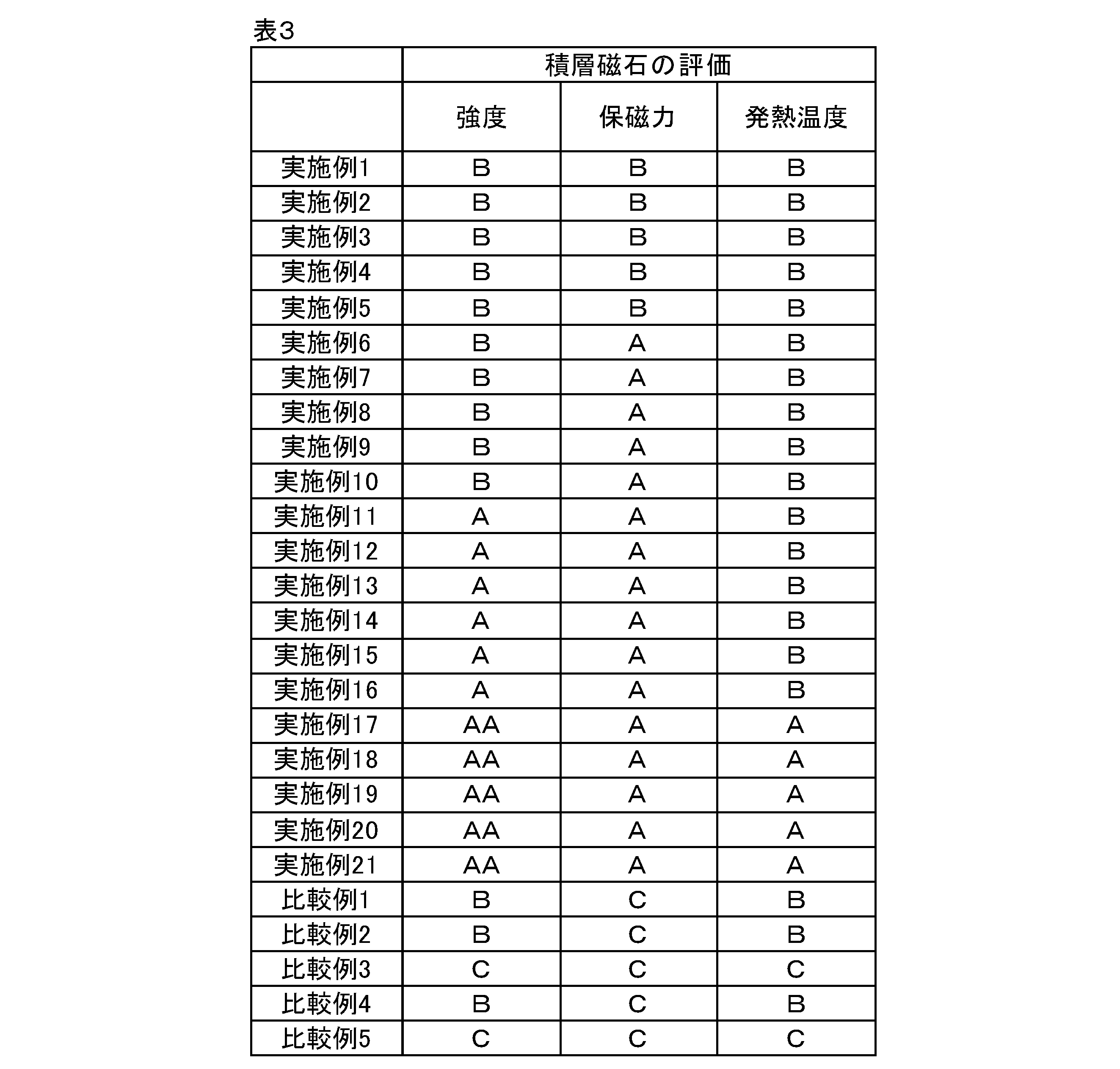
評価結果を表3に記載する。
実施例1-21は、下記要件(a)-(d)を満たしている。
・要件(a):上底面、下底面、及び側面を有し、希土類元素を含む板磁石が3以上用いられてなる。
・要件(b):板磁石と、絶縁接合層と、が交互に積層された積層磁石である。
・要件(c):上記の測定方法(1)による第1拡散深さαμmと、上記の測定方法(2)による第2拡散深さβμmが、
0.35≦β/α≦0.50
を満たす。
・要件(d):上記条件(3)~(6)を満たす第1領域における重希土類元素の量をγ質量%とし、上記条件(7)~(8)を満たす第2領域における前記重希土類元素の量をδ質量%とした場合に、
γ/δ≧5.0
を満たす。
・要件(a):上底面、下底面、及び側面を有し、希土類元素を含む板磁石が3以上用いられてなる。
・要件(b):板磁石と、絶縁接合層と、が交互に積層された積層磁石である。
・要件(c):上記の測定方法(1)による第1拡散深さαμmと、上記の測定方法(2)による第2拡散深さβμmが、
0.35≦β/α≦0.50
を満たす。
・要件(d):上記条件(3)~(6)を満たす第1領域における重希土類元素の量をγ質量%とし、上記条件(7)~(8)を満たす第2領域における前記重希土類元素の量をδ質量%とした場合に、
γ/δ≧5.0
を満たす。
これに対して、比較例1-5は以下の要件を満たしていない。
比較例1,5は、要件(c)、要件(d)を満たしてない。
比較例2-4は、要件(d)を満たしてない。
比較例1,5は、要件(c)、要件(d)を満たしてない。
比較例2-4は、要件(d)を満たしてない。
実施例1-21は、保磁力の評価が「A」又は「B」であった。これに対して、比較例1-5は、保磁力の評価が「C」であった。
実施例1-21は、過剰に重希土元素を使用することなく効率よく耐熱性を向上できることが示唆された。
実施例1-21は、過剰に重希土元素を使用することなく効率よく耐熱性を向上できることが示唆された。
また、実施例1-21のうち、更に下記要件(e)を満たしている実施例6-21は、保磁力の評価が「A」であった。要件(e)を満たすことで、より一層、耐熱性を向上できることが示唆された。
要件(e):特定中間磁石では、上底面と側面の角部、又は下底面と側面の角部が、重希土類元素の量が最大となる部位となっている。
要件(e):特定中間磁石では、上底面と側面の角部、又は下底面と側面の角部が、重希土類元素の量が最大となる部位となっている。
また、実施例1-21のうち、更に下記要件(f)を満たしている実施例11-21は、強度の評価が「AA」又は「A」であった。要件(f)を満たすことで、板磁石と絶縁接合層との密着強度を向上できることが示唆された。
要件(f):金属元素のフッ化物粒子が、重希土類元素と2種以上の金属成分を含む相と接している。
要件(f):金属元素のフッ化物粒子が、重希土類元素と2種以上の金属成分を含む相と接している。
また、実施例1-21のうち、更に下記要件(g)を満たしている実施例17-21は、強度の評価が「AA」であり、発熱温度の評価が「A」であった。要件(g)を満たすことで、強度を向上できること、渦電流損失を低減できることが示唆された。
要件(g):フッ化物粒子の平均粒子径は、2.0μm以上8.0μm以下である。
要件(g):フッ化物粒子の平均粒子径は、2.0μm以上8.0μm以下である。
5.実施例の効果
本実施例は、過剰に重希土元素を使用することなく効率よく耐熱性を持たせることができた。
本実施例は、過剰に重希土元素を使用することなく効率よく耐熱性を持たせることができた。
本発明は上記で詳述した実施形態に限定されず、本発明の請求項に示した範囲で様々な変形又は変更が可能である。
10…積層磁石
11…板磁石
11A1…上底面
11A2…下底面
11B…側面
13…絶縁接合層
14…フッ化物粒子
17…表面層
17A…特定の金属相
30…モーター
31…ステーター
33…ローター
34…回転軸
35…回転鉄心
37…軸孔
39…磁石孔
111…最上位磁石
112…中間磁石
112A…特定中間磁石
113…最下位磁石
E1,E2…角部
I…界面
11…板磁石
11A1…上底面
11A2…下底面
11B…側面
13…絶縁接合層
14…フッ化物粒子
17…表面層
17A…特定の金属相
30…モーター
31…ステーター
33…ローター
34…回転軸
35…回転鉄心
37…軸孔
39…磁石孔
111…最上位磁石
112…中間磁石
112A…特定中間磁石
113…最下位磁石
E1,E2…角部
I…界面
Claims (6)
- 上底面、下底面、及び側面を有し、希土類元素を含む板磁石が3以上用いられてなり、
前記板磁石と、絶縁接合層と、が交互に積層された積層磁石であって、
前記板磁石のうち、最上位に位置する最上位磁石及び最下位に位置する最下位磁石を除いた中間磁石のいずれかである特定中間磁石について、
前記積層磁石の重心を通り積層方向に延びる仮想直線をとり、前記仮想直線を含む仮想平面で、前記積層磁石の断面積が最も小さくなるように切断した断面を観察した場合に、
以下の測定方法(1)による第1拡散深さαμmと、以下の測定方法(2)による第2拡散深さβμmが、
0.35≦β/α≦0.50
を満たし、
下記条件(3)~(6)を満たす第1領域における重希土類元素の量をγ質量%とし、
下記条件(7)~(8)を満たす第2領域における前記重希土類元素の量をδ質量%とした場合に、
γ/δ≧5.0
を満たす、積層磁石。
測定方法(1):前記断面に現れる前記特定中間磁石の平面図形の重心を通り、かつ前記積層方向に延びる直線上を、前記上底面から平面図形の重心までの間についてライン分析し、その間の最大強度が1となるように規格化した前記重希土類元素の強度の第1プロファイルを得る。前記上底面の位置と、前記重希土類元素の強度がはじめて0.7となる位置との距離を第1拡散深さαμmとする。
測定方法(2):前記断面に現れる前記特定中間磁石の平面図形の重心を通り、かつ前記積層方向と直交する方向に延びる直線上を、前記側面から平面図形の重心までの間についてライン分析し、その間の最大強度が1となるように規格化した前記重希土類元素の強度の第2プロファイルを得る。前記側面の位置と、前記重希土類元素の強度がはじめて0.7となる位置との距離を第2拡散深さβμmとする。
条件(3):前記第1領域は、前記特定中間磁石と前記絶縁接合層との界面から前記特定中間磁石側に存在する。
条件(4):前記第1領域は、前記積層方向に10μm、かつ前記積層方向に直交する方向に50μmの長方形である。
条件(5):前記断面に現れる前記特定中間磁石の平面図形の重心を通り、かつ前記積層方向に延びる直線を引くと、前記長方形の中心は、前記直線上に存在する。
条件(6):前記長方形は、前記絶縁接合層に接している。
条件(7):前記第2領域は、前記積層方向に10μm、かつ前記積層方向に直交する方向に50μmの長方形である。
条件(8):前記長方形の中心は、前記断面に現れる前記特定中間磁石の平面図形の重心に位置する。
- 前記特定中間磁石では、前記上底面と前記側面の角部、又は前記下底面と前記側面の角部が、前記重希土類元素の量が最大となる部位となっている、請求項1に記載の積層磁石。
- 前記板磁石と前記絶縁接合層との前記界面から前記特定中間磁石側の深さ10μmまでの範囲には、周期表第2A族金属元素が存在している、請求項1又は請求項2に記載の積層磁石。
- 金属元素のフッ化物粒子が、前記重希土類元素と2種以上の金属成分を含む相と接している、請求項1又は請求項2に記載の積層磁石。
- 前記フッ化物粒子の平均粒子径は、2.0μm以上8.0μm以下である、請求項4に記載の積層磁石。
- 請求項1又は請求項2に記載の積層磁石を有する、モーター。
Applications Claiming Priority (2)
| Application Number | Priority Date | Filing Date | Title |
|---|---|---|---|
| JP2023-146618 | 2023-09-11 | ||
| JP2023146618A JP2025039991A (ja) | 2023-09-11 | 2023-09-11 | 積層磁石及びモーター |
Publications (1)
| Publication Number | Publication Date |
|---|---|
| WO2025057760A1 true WO2025057760A1 (ja) | 2025-03-20 |
Family
ID=95021242
Family Applications (1)
| Application Number | Title | Priority Date | Filing Date |
|---|---|---|---|
| PCT/JP2024/031029 Pending WO2025057760A1 (ja) | 2023-09-11 | 2024-08-29 | 積層磁石及びモーター |
Country Status (2)
| Country | Link |
|---|---|
| JP (1) | JP2025039991A (ja) |
| WO (1) | WO2025057760A1 (ja) |
Citations (3)
| Publication number | Priority date | Publication date | Assignee | Title |
|---|---|---|---|---|
| WO2014148355A1 (ja) * | 2013-03-18 | 2014-09-25 | インターメタリックス株式会社 | RFeB系焼結磁石製造方法及びRFeB系焼結磁石 |
| JP2019075493A (ja) * | 2017-10-18 | 2019-05-16 | Tdk株式会社 | 磁石接合体 |
| WO2022163407A1 (ja) * | 2021-01-26 | 2022-08-04 | Ndfeb株式会社 | Nd-Fe-B積層焼結磁石およびその製造方法 |
-
2023
- 2023-09-11 JP JP2023146618A patent/JP2025039991A/ja active Pending
-
2024
- 2024-08-29 WO PCT/JP2024/031029 patent/WO2025057760A1/ja active Pending
Patent Citations (3)
| Publication number | Priority date | Publication date | Assignee | Title |
|---|---|---|---|---|
| WO2014148355A1 (ja) * | 2013-03-18 | 2014-09-25 | インターメタリックス株式会社 | RFeB系焼結磁石製造方法及びRFeB系焼結磁石 |
| JP2019075493A (ja) * | 2017-10-18 | 2019-05-16 | Tdk株式会社 | 磁石接合体 |
| WO2022163407A1 (ja) * | 2021-01-26 | 2022-08-04 | Ndfeb株式会社 | Nd-Fe-B積層焼結磁石およびその製造方法 |
Also Published As
| Publication number | Publication date |
|---|---|
| JP2025039991A (ja) | 2025-03-24 |
Similar Documents
| Publication | Publication Date | Title |
|---|---|---|
| US9953750B2 (en) | Nd based sintered magnet | |
| US10943717B2 (en) | R-T-B based permanent magnet | |
| JP7180095B2 (ja) | R‐t‐b系焼結磁石 | |
| US20150155082A1 (en) | Rare Earth Laminated, Composite Magnets With Increased Electrical Rersistivity | |
| EP2590180A1 (en) | R-t-b type rare earth permanent magnet, motor, automobile, power generator, and wind power generation system | |
| US10784028B2 (en) | R-T-B based permanent magnet | |
| EP2477312B1 (en) | Method for manufacturing a rotor for a permanent magnet type rotary machine | |
| US11145444B2 (en) | R-T-B-based sintered magnet | |
| JP2025039997A (ja) | 積層磁石 | |
| US11837392B2 (en) | R-T-B based permanent magnet | |
| JP2011029293A (ja) | 希土類磁石及びそれを用いた輸送機器用磁石モータ | |
| WO2025057760A1 (ja) | 積層磁石及びモーター | |
| JP2025039990A (ja) | 積層磁石及びモーター | |
| JP2025039992A (ja) | 積層磁石及びモーター | |
| JP2025039993A (ja) | 希土類磁石 | |
| WO2025057758A1 (ja) | 積層磁石及びモーター | |
| WO2025057756A1 (ja) | 積層磁石及びモーター | |
| WO2025057759A1 (ja) | 積層磁石及びモーター | |
| JP2025039999A (ja) | モーター | |
| JP2025039998A (ja) | モーター | |
| WO2025057757A1 (ja) | モーター | |
| US11830646B2 (en) | R-T-B based permanent magnet | |
| JP2025177294A (ja) | 積層磁石及びモーター | |
| US11817241B2 (en) | Magnet structure | |
| JP2025177289A (ja) | 積層磁石及びモーター |
Legal Events
| Date | Code | Title | Description |
|---|---|---|---|
| 121 | Ep: the epo has been informed by wipo that ep was designated in this application |
Ref document number: 24865262 Country of ref document: EP Kind code of ref document: A1 |