WO2025057373A1 - 希土類焼結磁石、希土類焼結磁石の製造方法、回転子および回転機 - Google Patents
希土類焼結磁石、希土類焼結磁石の製造方法、回転子および回転機 Download PDFInfo
- Publication number
- WO2025057373A1 WO2025057373A1 PCT/JP2023/033580 JP2023033580W WO2025057373A1 WO 2025057373 A1 WO2025057373 A1 WO 2025057373A1 JP 2023033580 W JP2023033580 W JP 2023033580W WO 2025057373 A1 WO2025057373 A1 WO 2025057373A1
- Authority
- WO
- WIPO (PCT)
- Prior art keywords
- rare earth
- subphase
- main phase
- concentration
- sintered magnet
- Prior art date
- Legal status (The legal status is an assumption and is not a legal conclusion. Google has not performed a legal analysis and makes no representation as to the accuracy of the status listed.)
- Pending
Links
Images




Classifications
-
- H—ELECTRICITY
- H01—ELECTRIC ELEMENTS
- H01F—MAGNETS; INDUCTANCES; TRANSFORMERS; SELECTION OF MATERIALS FOR THEIR MAGNETIC PROPERTIES
- H01F1/00—Magnets or magnetic bodies characterised by the magnetic materials therefor; Selection of materials for their magnetic properties
- H01F1/01—Magnets or magnetic bodies characterised by the magnetic materials therefor; Selection of materials for their magnetic properties of inorganic materials
- H01F1/03—Magnets or magnetic bodies characterised by the magnetic materials therefor; Selection of materials for their magnetic properties of inorganic materials characterised by their coercivity
- H01F1/032—Magnets or magnetic bodies characterised by the magnetic materials therefor; Selection of materials for their magnetic properties of inorganic materials characterised by their coercivity of hard-magnetic materials
- H01F1/04—Magnets or magnetic bodies characterised by the magnetic materials therefor; Selection of materials for their magnetic properties of inorganic materials characterised by their coercivity of hard-magnetic materials metals or alloys
- H01F1/047—Alloys characterised by their composition
- H01F1/053—Alloys characterised by their composition containing rare earth metals
- H01F1/055—Alloys characterised by their composition containing rare earth metals and magnetic transition metals, e.g. SmCo5
- H01F1/057—Alloys characterised by their composition containing rare earth metals and magnetic transition metals, e.g. SmCo5 and IIIa elements, e.g. Nd2Fe14B
-
- H—ELECTRICITY
- H01—ELECTRIC ELEMENTS
- H01F—MAGNETS; INDUCTANCES; TRANSFORMERS; SELECTION OF MATERIALS FOR THEIR MAGNETIC PROPERTIES
- H01F41/00—Apparatus or processes specially adapted for manufacturing or assembling magnets, inductances or transformers; Apparatus or processes specially adapted for manufacturing materials characterised by their magnetic properties
- H01F41/02—Apparatus or processes specially adapted for manufacturing or assembling magnets, inductances or transformers; Apparatus or processes specially adapted for manufacturing materials characterised by their magnetic properties for manufacturing cores, coils, or magnets
Definitions
- This disclosure relates to rare earth sintered magnets, which are permanent magnets made by sintering materials containing rare earth elements, methods for manufacturing rare earth sintered magnets, rotors, and rotating machines.
- R-T-B system permanent magnets are known that have a tetragonal R 2 T 14 B intermetallic compound as the main phase.
- R is a rare earth element
- T is a transition metal element such as Fe (iron) or Fe partially substituted with Co (cobalt)
- B is boron.
- R-T-B system permanent magnets are used in various high-value-added parts, including industrial motors.
- Nd-Fe-B system sintered magnets in which R is Nd (neodymium), are used in various parts because of their excellent magnetic properties.
- industrial motors are often used in high-temperature environments exceeding 100°C, attempts have been made to improve the coercive force by adding heavy rare earth elements such as Dy (dysprosium) to Nd-T-B system sintered magnets.
- Nd-Fe-B sintered magnets have expanded, and the consumption of Nd and heavy rare earth elements such as Dy and Tb (terbium) has increased.
- Nd and heavy rare earth elements are expensive and have a high regional distribution, which poses procurement risks. For this reason, technology to reduce the consumption of Nd and heavy rare earth elements is being researched.
- Patent Document 1 discloses an R-T-B system sintered magnet including main phase particles made of R 2 T 14 B crystals, where R is one or more rare earth elements essentially including a heavy rare earth element RH, T is one or more transition metal elements essentially including Fe or Fe and Co, and B is boron, and a part of the main phase particles includes a plurality of low heavy rare earth element crystal phases and a plurality of nonmagnetic R-rich phases.
- the low heavy rare earth element crystal phase is made of R 2 T 14 B crystals and is a phase in which the concentration of the heavy rare earth element is relatively low compared to the concentration of the heavy rare earth element in the entire main phase particle.
- the nonmagnetic R-rich phase is a phase in which the content of R is 70 at.
- a part of the main phase particles has one type of core-shell structure including a core portion and a shell portion surrounding the periphery of the core portion and having a total heavy rare earth element concentration lower than that of the core portion. According to the technique described in Patent Document 1, it is possible to obtain a low-cost RTB based sintered magnet that has improved coercive force.
- Patent Document 2 discloses a method for producing a rare earth magnet , which comprises a first step of producing a sintered body having a structure represented by the composition formula (R11 - xR2x ) aTMbBcMd and consisting of a main phase and a grain boundary phase, a second step of producing a rare earth magnet precursor by subjecting the sintered body to hot plastic working, and a third step of producing a rare earth magnet by diffusing and infiltrating a melt of an R3-M modifier alloy into the grain boundary phase of the rare earth magnet precursor.
- R1 is one or more rare earth elements including Y (yttrium), R2 is a rare earth element different from R1, TM is a transition metal including one or more of Fe, Ni (nickel), and Co, B is boron, and M is one or more of Ti (titanium), Ga (gallium), Zn (zinc), Si (silicon), Al (aluminum), Nb (niobium), Zr (zirconium), Ni, Co, Mn (manganese), V (vanadium), W (tungsten), Ta (tantalum), Ge (germanium), Cu (copper), Cr (chromium), Hf (hafnium), Mo (molybdenum), P (phosphorus), C (carbon), Mg (magnesium), Hg (mercury), Ag (silver), and Au (gold).
- TM is a transition metal including one or more of Fe, Ni (nickel), and Co
- B is boron
- M is one or more of Ti (titanium),
- R3 is a rare earth element including R1 and R2.
- hot processing According to the technology described in Patent Document 2, it is possible to reduce the heavy rare earth element and produce a rare earth magnet that is excellent not only in magnetization but also in coercivity performance, even when the main phase ratio is high.
- a phase containing heavy rare earth elements is present in the main phase, which allows for improved coercivity, but it does not provide the residual magnetic flux density required for industrial motors and the like, and there is a possibility that the magnetic properties may deteriorate due to thermal load.
- rare earth magnets manufactured using the manufacturing method described in Patent Document 2 can reduce the heavy rare earth elements and improve coercivity, but because the manufacturing method includes hot working, the grain size of the main phase becomes smaller, which results in problems with the residual magnetic flux density and magnetization performance of the rare earth magnets manufactured.
- the present disclosure has been made in light of the above, and aims to obtain a rare earth sintered magnet that can improve coercivity without reducing residual magnetic flux density and magnetization performance compared to conventional magnets.
- the rare earth sintered magnet according to the present disclosure has a main phase that satisfies the general formula (Nd, Pr, RH, R)-Fe-B-M and contains crystal grains based on the Nd 2 Fe 14 B crystal structure, and a subphase formed between the main phase and the main phase, where RH is a heavy rare earth element containing at least one of Dy and Tb, R is one or more rare earth elements selected from the group consisting of Nd, Pr (praseodymium), Dy, and Tb, and M is one or more elements selected from the group consisting of Ga, Al, Cu, and Co.
- the main phase has a core portion and a shell portion that covers the core portion.
- the main phase has a first main phase in which CNd>CPr and a second main phase in which CNd ⁇ CPr, where CNd is the concentration of Nd in the core portion and CPr is the concentration of Pr in the core portion.
- the concentration of the heavy rare earth element RH in the core portion of the first main phase is higher than the concentration of the heavy rare earth element RH in the core portion of the second main phase.
- the first main phase and the second main phase are mixed.
- the subphase has a crystalline first subphase and a second subphase, each of which is mainly composed of an oxide phase expressed as (Nd, Pr, RH, La, Sm)-O containing the element M as a trace component.
- the concentration of the element M is higher in the second subphase than in the first subphase.
- the rare earth sintered magnet disclosed herein has the advantage of being able to improve coercivity without reducing residual magnetic flux density and magnetization performance compared to conventional magnets.
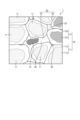
- FIG. 1 is a schematic diagram showing an example of the structure of a rare earth sintered magnet in a sintered state according to the first embodiment
- FIG. 13 is a schematic diagram showing an example of the structure of a rare earth sintered magnet in a sintered state according to the second embodiment
- FIG. 13 is a cross-sectional view showing a schematic example of the configuration of a rotor equipped with a rare earth sintered magnet according to a fourth embodiment.
- FIG. 13 is a cross-sectional view showing a schematic example of a configuration of a rotating machine according to a fifth embodiment.
- a trace of the composition image obtained by analyzing the cross section of the rare earth sintered magnets according to Examples 1 to 8 with a Field Emission-Electron Probe Micro Analyzer (FE-EPMA).
- FE-EPMA Field Emission-Electron Probe Micro Analyzer
- FIG. 1 is a diagram showing a schematic diagram of an example of the structure of a rare earth sintered magnet in a sintered state according to the first embodiment.
- the rare earth sintered magnet 1 according to the first embodiment has a main phase 10 that satisfies the general formula (Nd, Pr, RH, R)-Fe-B-M and contains crystal grains based on a Nd 2 Fe 14 B crystal structure, and a subphase 20 that exists between the main phase 10 and the main phase 10.
- the main phase 10 has a core portion and a shell portion that covers the core portion.
- RH is a heavy rare earth element, and in one example, is one or more elements selected from the group of Dy, Tb, Gd (gadolinium), and Ho (holmium), and preferably, RH is a heavy rare earth element containing at least one of Dy and Tb.
- R is one or more rare earth elements selected from the group other than Nd, Pr, and RH.
- M is one or more elements selected from the group of Ga, Al, Cu, and Co.
- the shell portion has a different composition from the core portion and is provided so as to cover the core portion.
- the rare earth sintered magnet 1 is expressed by the general formula (Nd a Pr b R c RH d )Fe e B f M g, where RH is one or more heavy rare earth elements selected from the group consisting of Dy, Tb, Gd, and Ho, R is a rare earth element other than Nd , Pr , and RH , and M is one or more elements selected from the group consisting of Ga, Al, Cu, and Co. It is desirable that a, b, c, d, e, f, and g satisfy the following relational expressions.
- the main phase 10 has a tetragonal R2Fe14B crystal structure in which a portion of the Nd sites is replaced with Pr, a heavy rare earth element RH, and one or more rare earth elements R selected from among Nd, Pr, and the heavy rare earth elements RH . That is, the main phase 10 has a composition formula of (Nd, Pr, RH, R )2Fe14B .
- the element M may be incorporated into the main phase 10. When the element M is Co or Cu, which is a transition element, it is considered that the element M replaces a portion of the Fe sites of the Nd2Fe14B crystal structure.
- the main phase 10 when the concentration of Nd in the core portions 11c and 12c is CNd and the concentration of Pr in the core portions 11c and 12c is CPr, the main phase 10 has a first main phase 11 where CNd>CPr and a second main phase 12 where CNd ⁇ CPr, and the first main phase 11 and the second main phase 12 are mixed. Also, the concentration of the heavy rare earth element RH in the core portion 11c of the first main phase 11 is higher than the concentration of the heavy rare earth element RH in the core portion 12c of the second main phase 12.
- the concentration of the heavy rare earth element RH in the core portion 11c of the first main phase 11 is C1RH and the concentration of the heavy rare earth element RH in the core portion 12c of the second main phase 12 is C2RH, C1RH>C2RH.
- the first main phase 11 has a core portion 11c and a shell portion 11s that has a different composition from the core portion 11c and covers the core portion 11c.
- the second main phase 12 has a core portion 12c and a shell portion 12s that has a different composition from the core portion 12c and covers the core portion 12c.
- the main phase 10 when the sum of the concentration of Nd and the concentration of the heavy rare earth element RH in the core portions 11c, 12c is C(Nd, RH), the main phase 10 has a first main phase 11 where C(Nd, RH)>CPr and a second main phase 12 where C(Nd, RH) ⁇ CPr, and it can be said that the first main phase 11 and the second main phase 12 are mixed together.
- the rare earth sintered magnet 1 has two main phases 10, the first main phase 11 and the second main phase 12. Focusing on the cores 11c and 12c of the two main phases 10, the sum of the Nd concentration and the heavy rare earth element RH concentration is higher than the Pr concentration in the first main phase 11, and conversely, the Pr concentration is higher than the sum of the Nd concentration and the heavy rare earth element RH concentration in the second main phase 12.
- concentration difference shown as "C1RH>C2RH” means that a mapping analysis using an electron probe microanalyzer (EPMA) has revealed a clear difference in the detection intensity of the heavy rare earth element RH in the core portion 11c of the first main phase 11 and the core portion 12c of the second main phase 12.
- EPMA electron probe microanalyzer
- the detection intensity by EPMA is higher than the average detection intensity of the heavy rare earth element RH
- the detection intensity by EPMA is near the lower limit of the detection intensity of the heavy rare earth element RH, or the detection intensity by EPMA is lower than the average detection intensity of the heavy rare earth element RH.
- the heavy rare earth element RH is contained in the core portion 11c of the first main phase 11, but is hardly contained in the core portion 12c of the second main phase 12.
- the concentration difference shown in "the first main phase 11 where C(Nd, RH)>CPr and the second main phase 12 where C(Nd, RH) ⁇ CPr" means that a clear difference has been found between the detection intensity of Nd and the heavy rare earth element RH and the detection intensity of Pr by mapping analysis using EPMA.
- the detection intensity by EPMA for the concentration of Nd and the concentration of the heavy rare earth element RH in the core portion 11c is higher than the average detection intensity of Nd and the heavy rare earth element RH, and for the concentration of Pr, the detection intensity by EPMA is near the lower limit of the detection intensity of Pr, or the detection intensity by EPMA is lower than the average detection intensity of Pr.
- the second main phase 12 is the opposite of the case of the first main phase 11.
- the rare earth sintered magnet 1 according to the first embodiment satisfies the relational expressions C1Nd>C2Nd, C1Pr ⁇ C2Pr when the Nd concentration in the core portion 11c of the first main phase 11 is C1Nd, the Nd concentration in the core portion 12c of the second main phase 12 is C2Nd, the Pr concentration in the core portion 11c of the first main phase 11 is C1Pr, and the Pr concentration in the core portion 12c of the second main phase 12 is C2Pr.
- the Nd concentration is higher in the core portion 11c of the first main phase 11 than in the core portion 12c of the second main phase 12, and conversely, the Pr concentration is higher in the core portion 12c of the second main phase 12 than in the core portion 11c of the first main phase 11.
- This concentration difference also means that there is a difference in the detection intensity of Nd and Pr by the mapping analysis using the EPMA described above.
- the EPMA detection strength of Nd in the core portion 11c of the first main phase 11 is higher than the average Nd detection strength
- the EPMA detection strength of Nd in the core portion 12c of the second main phase 12 is lower than the average Nd detection strength.
- the first main phases 11 having C(Nd, RH)>CPr are more present than the second main phases 12 having C(Nd, RH) ⁇ CPr.
- the number of the first main phases 11 having the composition formula of (Nd, RH)2Fe14B is greater than the number of the second main phases 12 having the composition formula of Pr2Fe14B .
- the overall crystal grains are also suppressed from becoming finer, so that it is possible to obtain magnetic properties that are superior to those of the prior art while ensuring magnetization.
- the rare earth sintered magnet 1 according to embodiment 1 focusing on the shell portions 11s, 12s of the core-shell structure, when the concentration of Nd in the shell portions 11s, 12s is SNd, the concentration of Pr in the shell portions 11s, 12s is SPr, the concentration of the heavy rare earth element RH in the core portions 11c, 12c is CRH, and the concentration of the heavy rare earth element RH in the shell portions 11s, 12s is SRH, the first main phase 11 satisfies the relational expressions CNd>SNd, CPr ⁇ SPr, CRH>SRH, and the second main phase 12 satisfies the relational expressions CNd ⁇ SNd, CPr>SPr, CRH ⁇ SRH.
- the concentration of Nd and the concentration of the heavy rare earth element RH are lower than those in the core portion 11c, but the concentration of Pr is higher than those in the core portion 11c.
- the concentration of Pr is lower than those in the core portion 12c, but the concentration of Nd and the concentration of the heavy rare earth element RH are higher than those in the core portion 12c.
- the rare earth sintered magnet 1 focusing on the shell portions 11s, 12s of the core-shell structure, when the sum of the Nd concentration and the heavy rare earth element RH concentration in the shell portions 11s, 12s is S(Nd, RH) and the Pr concentration in the shell portions 11s, 12s is SPr, the first main phase 11 satisfies the relational expression C(Nd, RH)>S(Nd, RH), CPr ⁇ SPr, and the second main phase 12 satisfies the relational expression C(Nd, RH) ⁇ S(Nd, RH), CPr>SPr.
- the shell portion 11s of the first main phase 11 the sum of the Nd concentration and the heavy rare earth element RH concentration is smaller than that in the core portion 11c, but the Pr concentration is higher than that in the core portion 11c.
- the shell portion 12s of the second main phase 12 has a lower concentration of Pr than the core portion 12c, but the sum of the concentration of Nd and the concentration of the heavy rare earth element RH is higher than that of the core portion 12c.
- a main phase 10 having a shell portion 11s with a high concentration of Pr like the first main phase 11, it is possible to improve the coercive force. Furthermore, by forming a main phase 10 having a shell portion 12s with a high sum of the concentration of Nd and the concentration of the heavy rare earth element RH, like the second main phase 12, it is possible to suppress a decrease in the residual magnetic flux density while maintaining the coercive force. By selectively controlling the structure to have such a structure, the rare earth sintered magnet 1 is able to exhibit superior magnetic properties compared to conventional magnets.
- the average grain size of the crystal grains of the main phase 10 is preferably 100 ⁇ m or less, and more preferably 0.5 ⁇ m to 50 ⁇ m to improve the magnetic properties. Furthermore, by making the grain size approximately 1 ⁇ m to 10 ⁇ m, the grain size becomes different from the microstructure produced by hot working, good magnetization performance is maintained, and it is possible to obtain a rare earth sintered magnet 1 with superior magnetic properties compared to conventional magnets.
- the subphase 20 has a crystalline first subphase 21 mainly composed of an oxide phase represented by (Nd, Pr, RH, R)-O containing the element M as a trace component, and a crystalline second subphase 22 mainly composed of an oxide phase represented by (Nd, Pr, RH, R)-O containing the element M as a trace component.
- O is oxygen.
- the crystalline subphase 20 is a general term for the crystalline first subphase 21 and the crystalline second subphase 22.
- (Nd, Pr, RH, R) means that a portion of Nd and Pr is replaced by a heavy rare earth element RH and a rare earth element R other than Nd and Pr.
- the R of the first subphase 21 and the R of the second subphase 22 may be the same rare earth element, may be partially different rare earth elements, or may be different rare earth elements. Note that the main component elements are listed in parentheses, so the first subphase 21 and the second subphase 22 may contain trace amounts of other components in addition to the elements listed in parentheses.
- the subphase 20, i.e., the first subphase 21 and the second subphase 22, contain the element M as a trace component as described above.
- the concentration of element M contained in the first subphase 21 and the second subphase 22 is higher in the second subphase 22 than in the first subphase 21.
- the concentration of element M in the first subphase 21 is Cs1M
- the concentration of element M in the second subphase 22 is Cs2M
- the relationship Cs1M ⁇ Cs2M is satisfied.
- the concentration of element M is higher in the second subphase 22 than in the first subphase 21 means that, as a result of mapping analysis using EPMA, the detection intensity of element M is higher on average in the second subphase 22 than in the first subphase 21. More specifically, this means that the intensity of element M detected by EPMA in the second subphase 22 is higher than the average intensity of element M detected by EPMA, and the intensity of element M detected by EPMA in the first subphase 21 is lower than the average intensity of element M detected by EPMA.
- the element M is present in high concentration in the second subphase 22, forming a non-magnetic phase that magnetically separates the main phases 10, thereby contributing to improved magnetic properties.
- concentration of element M higher in the second subphase 22 than in the first subphase 21
- high magnetic properties, particularly coercive force can be obtained and the deterioration of the magnetic properties associated with an increase in temperature can be suppressed.
- the rare earth sintered magnet 1 according to the first embodiment satisfies the general formula (Nd, Pr, RH, R)-Fe-B-M, where RH is a heavy rare earth element, R is one or more rare earth elements selected from the group consisting of Nd, Pr, and the heavy rare earth element RH, and M is one or more elements selected from the group consisting of Ga, Al, Cu, and Co.
- the rare earth sintered magnet 1 according to the first embodiment comprises a main phase 10 including crystal grains based on an Nd2Fe14B crystal structure, and a subphase 20 present between the main phases 10 and 10.
- the main phase 10 has core portions 11c, 12c and shell portions 11s, 12s covering the core portions 11c, 12c.
- the main phase 10 has a first main phase 11 in which CNd>CPr and a second main phase 12 in which CNd ⁇ CPr, the first main phase 11 has a higher concentration of the heavy rare earth element RH than the second main phase 12, and the first main phase 11 and the second main phase 12 are mixed together.
- the subphase 20 has a crystalline first subphase 21 and a second subphase 22 that are mainly composed of an oxide phase expressed as (Nd, Pr, RH, R)-O containing the element M as a trace component, and the second subphase 22 has a higher concentration of the element M contained therein than the first subphase 21.
- This configuration makes it possible to obtain a rare earth sintered magnet 1 that has improved magnetic properties and magnetization compared to conventional magnets while suppressing the use of Nd and the heavy rare earth element RH.
- the R-T-B system sintered magnet described in Patent Document 1 is compared with the rare earth sintered magnet 1 according to the first embodiment.
- the R-T-B system sintered magnet described in Patent Document 1 has one or more rare earth elements, with the heavy rare earth element RH being essential, and has one type of main phase particle composed of a core portion and a shell portion.
- all main phase particles in the R-T-B system sintered magnet contain the heavy rare earth element RH.
- the main phase 10 has a first main phase 11 and a second main phase 12, and the concentration of the heavy rare earth element RH is lower in the second main phase 12 than in the first main phase 11.
- the core portion 11c of the first main phase 11 contains the heavy rare earth element RH, but the core portion 12c of the second main phase 12 contains almost no heavy rare earth element RH.
- the heavy rare earth element RH is selectively arranged in the main phase 10.
- the rare earth sintered magnet 1 according to embodiment 1 which has a main phase 10 having a first main phase 11 and a second main phase 12 in which the concentration of the heavy rare earth element RH is lower than that of the first main phase 11, can reduce the amount of heavy rare earth element RH used.
- the heavy rare earth element RH is selectively arranged, and the amount of heavy rare earth element RH used can be reduced compared to the R-T-B based sintered magnet described in Patent Document 1.
- the rare earth sintered magnet 1 according to embodiment 1 Compare the rare earth magnet manufactured by the technique described in Patent Document 2 with the rare earth sintered magnet 1 according to embodiment 1.
- a larger amount of heavy rare earth element RH must be added compared to the rare earth sintered magnet 1 according to embodiment 1, as shown in the examples described later.
- the rare earth sintered magnet 1 according to embodiment 1 can reduce the amount of heavy rare earth element RH used compared to the technique described in Patent Document 2.
- the magnetic properties of the rare earth magnet manufactured by the technique described in Patent Document 2 will be lower than the magnetic properties of the rare earth sintered magnet 1 according to embodiments 1 and 2.
- the first main phase 11 and the second main phase 12 are made to satisfy the relational expressions C1Nd>C2Nd, C1Pr ⁇ C2Pr.
- the number of first main phases 11 is made greater than the number of second main phases 12.
- the first main phase 11 is made to satisfy the relational expressions CNd>SNd, CPr ⁇ SPr, CRH>SRH
- the second main phase 12 is made to satisfy the relational expressions CNd ⁇ SNd, CPr>SPr, CRH ⁇ SRH. This also makes it possible to obtain a rare earth sintered magnet 1 with improved magnetic properties and magnetizability while limiting the use of Nd and the heavy rare earth element RH.
- the main phase 10 contains the heavy rare earth element RH and the subphase 22 mainly contains the element M
- a rare earth sintered magnet 1 having a significantly improved coercive force compared to conventional magnets is obtained. Furthermore, as shown in the examples described below, a rare earth sintered magnet 1 having a better temperature coefficient of coercive force compared to conventional magnets is obtained. Therefore, even when a thermal load is applied to the rare earth sintered magnet 1, the coercive force is greater than conventional magnets, and the decrease in coercive force with increasing temperature is also more gradual than conventional magnets. In other words, since the coercive force is significantly improved compared to conventional rare earth sintered magnets, the magnetic properties when a thermal load is applied to the rare earth sintered magnet 1 are also better than conventional magnets.
- Embodiment 2 In the second embodiment, La and Sm are selected as the rare earth element R in the rare earth sintered magnet 1 according to the first embodiment.
- FIG. 2 is a diagram showing a schematic example of the structure of a rare earth sintered magnet in a sintered state according to embodiment 2. Note that the same components as those in embodiment 1 are given the same reference numerals and their description will be omitted.
- the rare earth sintered magnet 1 according to embodiment 2 has a main phase 10 and a subphase 20.
- the main phase 10 includes a first main phase 11 and a second main phase 12 as described in embodiment 1.
- the subphase 20 includes a first subphase 21 and a second subphase 22 as described in embodiment 1.
- the main phase 10 has a composition formula of (Nd, Pr, RH, La, Sm) 2 Fe 14 B.
- the reason why the rare earth element R of the rare earth sintered magnet 1 having the tetragonal R 2 Fe 14 B crystal structure is a rare earth element containing La and Sm is that a practical rare earth sintered magnet 1 that can significantly suppress the deterioration of the magnetic properties with temperature increase can be obtained by adding La and Sm to the composition, based on the calculation results of the magnetic interaction energy using the molecular orbital method.
- Nd and Pr can be relatively diffused into the main phase 10, and the crystal magnetic anisotropy of the main phase 10 can be increased.
- the subphase 20 has a feature that the concentration of Sm in the first subphase 21 is higher than that in the second subphase 22.
- the first subphase 21 forms an Sm-enriched portion having a higher concentration of Sm than the second subphase 22. This provides an effect of suppressing the deterioration of the magnetic properties not only at room temperature but also with increasing temperature.
- the element M may enter the low concentration portion 42 where the concentration of Sm in the first subphase 21 is lower than the surrounding area. In this case, the concentration of element M in the low concentration portion 42 will be higher than the concentration of element M in the high concentration portion 41.
- the concentration of element M is higher in the second subphase 22 than in the first subphase 21.
- Sm and element M are segregated in different subphases 20. Since Sm is present in high concentration in the first subphase 21, it relatively diffuses Nd into the main phase 10 and improves the crystal magnetic anisotropy of the main phase 10. Furthermore, since Sm is also present in the crystal grains of the main phase 10, it contributes to improving the residual magnetic flux density by binding to the same magnetization direction as Fe, which is a ferromagnetic material. Since element M is present in high concentration in the second subphase 22, it forms a nonmagnetic phase that magnetically separates the main phases 10, contributing to improving the magnetic properties. Since Sm and element M are present in high concentration in each of the different subphases 20, it is possible to improve both the residual magnetic flux density and the coercive force.
- the concentration of Sm is higher in the first subphase 21 than in the second subphase 22
- the detection intensity of Sm is higher on average in the first subphase 21 than in the second subphase 22. More specifically, this means that the intensity of Sm detected by EPMA in the first subphase 21 is higher than the average intensity of Sm detected by EPMA, and the intensity of Sm detected by EPMA in the second subphase 22 is lower than the average intensity of Sm detected by EPMA.
- the crystalline subphase 20 is a general term for the crystalline first subphase 21 and the crystalline second subphase 22, and exists between the main phase 10.
- the crystalline first subphase 21 is represented by (Nd, Pr, RH, La, Sm)-O containing the element M as a trace component
- the crystalline second subphase 22 is represented by (Nd, Pr, RH, La)-O containing the element M as a trace component.
- (Nd, Pr, RH, La, Sm) means that a part of Nd and Pr is replaced by the heavy rare earth elements RH, La, and Sm.
- the first subphase 21 and the second subphase 22 may contain trace amounts of other components in addition to the elements shown in parentheses.
- the second subphase 22 represented by (Nd, Pr, RH, La)-O containing the element M as a trace component contains a very small amount of Sm.
- the rare earth sintered magnet 1 there is a difference in the concentrations of La and Sm between the main phase 10 and the subphase 20, and La and Sm are segregated more in the subphase 20 than in the main phase 10.
- the sum of the concentrations of La in the first subphase 21 and the second subphase 22 is greater than or equal to the concentration of La in the main phase 10
- the sum of the concentrations of Sm in the first subphase 21 and the second subphase 22 is greater than or equal to the concentration of Sm in the main phase 10.
- the concentrations of La and Sm in the subphase 20 are greater than or equal to the concentrations of La and Sm in the main phase 10.
- the concentration of La in the main phase 10 here is the sum of the concentration of La in the first main phase 11 and the concentration of La in the second main phase 12. That is, the sum of the La concentrations in the first subphase 21 and the second subphase 22 is higher than the sum of the La concentrations in the first main phase 11 and the second main phase 12.
- the Sm concentration in the main phase 10 is the sum of the Sm concentration in the first main phase 11 and the Sm concentration in the second main phase 12. That is, the sum of the Sm concentrations in the first subphase 21 and the second subphase 22 is higher than the sum of the Sm concentrations in the first main phase 11 and the second main phase 12.
- the concentration of La contained in the main phase 10 is X
- the concentration of La contained in the first subphase 21 is X1
- the concentration of La contained in the second subphase 22 is X2
- the concentration of Sm contained in the main phase 10 is Y
- the concentration of Sm contained in the first subphase 21 is Y1
- the concentration of Sm contained in the second subphase 22 is Y2
- the concentrations of Nd and Pr contained in the main phase 10 satisfy the relationship of the following equations (2) and (3).
- the La concentration in the main phase 10 is the sum of the La concentrations in the first main phase 11 and the second main phase 12
- the Sm concentration in the main phase 10 is the sum of the Sm concentrations in the first main phase 11 and the second main phase 12.
- the La concentration in the main phase 10 indicates the average of the La concentrations in the first main phase 11 and the second main phase 12
- the Sm concentration in the main phase 10 indicates the average of the Sm concentrations in the first main phase 11 and the second main phase 12.
- the La concentration in the subphase 20, i.e., the sum of the La concentrations in the first subphase 21 and the second subphase 22 means the average La concentration in the first subphase 21 and the second subphase 22
- the Sm concentration in the subphase 20 i.e., the sum of the Sm concentrations in the first subphase 21 and the second subphase 22 means the average Sm concentration in the first subphase 21 and the second subphase 22.
- La is present in high concentrations at the grain boundaries during the manufacturing process, particularly during heat treatment, and thus diffuses Nd and Pr relatively into the main phase 10.
- Nd and Pr in the main phase 10 are not consumed at the grain boundaries, improving the crystalline magnetic anisotropy.
- Sm is also present in high concentrations in the subphase 20, particularly the first subphase 21, compared to the main phase 10, and thus, like La, diffuses Nd relatively into the main phase 10, improving the crystalline magnetic anisotropy.
- the subphase 20 contains the heavy rare earth element RH, and therefore the first subphase 21 and the second subphase 22 also contain the heavy rare earth element RH, but in the subphase 20, the concentration of the heavy rare earth element RH is higher in the first subphase 21 than in the second subphase 22.
- the first subphase 21 also has a high concentration portion 41 in which the concentration of Sm is higher than the surrounding area, and a low concentration portion 42 in which the concentration of Sm is lower than the high concentration portion 41.
- the distribution of the heavy rare earth element RH differs between the first subphase 21 and the second subphase 22.
- the heavy rare earth element RH is uniformly distributed within the second subphase 22.
- the heavy rare earth element RH is not distributed uniformly in the first subphase 21, but is selectively distributed between the outer periphery of the first subphase 21 and the high concentration portion 41, i.e., in the inner periphery of the outer periphery of the first subphase 21.
- the inner periphery of the outer periphery of the first subphase 21 corresponds to the low concentration portion 42.
- the low concentration portion 42 exists so as to selectively surround the outer periphery of the high concentration portion 41 of the first subphase 21, in which the concentration of Sm is high, and the heavy rare earth element RH exists in the low concentration portion 42. From this, it can be said that the first subphase 21 has a high concentration portion 41 in which Sm is concentrated, and a heavy rare earth element-containing portion that is the low concentration portion 42 in which the heavy rare earth element RH exists and that selectively surrounds the outer periphery of the high concentration portion 41.
- the outer periphery of the first subphase 21 is the boundary between the first subphase 21 and the main phase 10.
- the first subphase 21 and the second subphase 22 containing the heavy rare earth element RH are present between the main phases 10. Therefore, it can be considered that the heavy rare earth element RH penetrates into a portion of the surface of the main phase 10 that contacts the first subphase 21 and the second subphase 22 containing the heavy rare earth element RH.
- the second embodiment can also suppress a decrease in the residual magnetic flux density while improving the coercive force of the rare earth sintered magnet 1.
- Fig. 3 is a diagram showing atomic sites in the tetragonal Nd2Fe14B crystal structure.
- the crystal structure shown in Fig. 3 is, for example, shown in Fig. 1 of Reference Technical Document 1 below.
- the substituted site is determined by the value of the stabilization energy due to the substitution, which is calculated by band calculation and molecular field approximation of the Heisenberg model. (Reference 1) JFHerbst et al. “Relationships between crystal structure and magnetic properties in Nd 2 Fe 14 B”. PHYSICAL REVIEW B. 1984, Vol. 29, No. 7, p. 4176-4178.
- the stabilization energy of La can be calculated by the energy difference between ( Nd7La1 ) Fe56B4 +Nd and Nd8 ( Fe55La1 ) B4 +Fe using a Nd8Fe56B4 crystal cell.
- the smaller the energy value the more stable the site is when an atom is substituted. That is, La is more likely to be substituted at the atomic site with the smallest energy among the atomic sites.
- Table 1 shows the stabilization energy of La at each substitution site when the environmental temperature is changed.
- the stable substitution site of La is the Nd(f) site at temperatures of 1000K or higher, and the Fe(c) site at temperatures of 293K and 500K.
- the rare earth sintered magnet 1 according to the second embodiment is produced by heating the raw material of the rare earth sintered magnet 1 to a temperature of 1000K or higher, melting it, and then quenching it. For this reason, it is considered that the raw material of the rare earth sintered magnet 1 is maintained at a temperature of 1000K or higher, i.e., 727°C or higher, and preferably at about 1300K, i.e., 1027°C. At that time, it is considered that La is substituted at the Nd(f) site or Nd(g) site.
- La is preferentially substituted at the energetically stable Nd(f) site, but it is also possible that La is substituted at the Nd(g) site, which has a small energy difference among the substitution sites of La. For this reason, the Nd(g) site is also listed as a candidate for the substitution site of La.
- the rare earth sintered magnet 1 is manufactured by the manufacturing method described later, although the temperature is 1000K or more during sintering, the Fe(c) site described in Table 1 is repeatedly maintained in an energetically stable temperature range by going through the first aging step, the second aging step, the third aging step, the fourth aging step, and the cooling step described later. In other words, the substitution of La at the Nd site of the main phase 10 is maintained in an unstable energy state.
- La is mainly substituted at the Nd site of the main phase 10, but in the rare earth sintered magnet 1 manufactured by the manufacturing method described later, by deliberately holding the rare earth sintered magnet 1 in a temperature range with an unstable energy state repeatedly with respect to the Nd site of the main phase 10, a certain amount of La is selectively released from the Nd site of the main phase 10, and La segregates to the subphase 20.
- the main phase 10 promotes the formation of a characteristic structure called a core-shell structure.
- the stabilization energy of Sm can be calculated from the energy difference between ( Nd7Sm1 ) Fe56B4 +Nd and Nd8 ( Fe55Sm1 ) B4 + Fe .
- the lattice constant in the tetragonal R2Fe14B crystal structure does not change due to the substitution of atoms.
- Table 2 shows the stabilization energy of Sm at each substitution site when the environmental temperature is changed.
- the stable substitution site for Sm is the Nd(g) site at all temperatures. It is thought that Sm is preferentially substituted at the energetically stable Nd(g) site, but substitution at the Nd(f) site, which has a small energy difference among the substitution sites for Sm, is also possible.
- rare earth sintered magnet 1 When rare earth sintered magnet 1 is manufactured by the manufacturing method described below, substitution at the Nd(g) site of main phase 10 is the most stable in terms of energy. However, as described above, by maintaining the temperature range in which substitution of La at the Nd site of main phase 10 becomes unstable, some Sm is also released from the Nd site of main phase 10 together with La and segregates into subphase 20. As a result, there is a difference in the concentrations of La and Sm between main phase 10 and subphase 20, and the sum of the concentrations of La in first subphase 21 and second subphase 22 is equal to or greater than the concentration of La in main phase 10, and the sum of the concentrations of Sm in first subphase 21 and second subphase 22 is equal to or greater than the concentration of Sm in main phase 10.
- the average concentration of La in the first subphase 21 and the second subphase 22 is equal to or greater than the average concentration of La in the first main phase 11 and the second main phase 12
- the average concentration of Sm in the first subphase 21 and the second subphase 22 is equal to or greater than the average concentration of Sm in the first main phase 11 and the second main phase 12.
- Nd is produced as a representative example, as shown in Figure 3, but since Nd and Pr are produced as a mixture, as typified by Di (didymium), it is thought that the energy levels of Nd and Pr are close. Therefore, the same can be said when Nd is replaced with Pr.
- Di didymium
- the rare earth sintered magnet 1 of the second embodiment satisfies the general formula (Nd, Pr, RH, R)-Fe-B-M when RH is one or more heavy rare earth elements selected from the group of Dy, Tb, Gd, and Ho, R is one or more rare earth elements selected from the group of other than Nd, Pr, and RH, and M is one or more elements selected from the group of Ga, Al, Cu, and Co.
- the magnet includes a main phase 10 including crystal grains based on the Nd 2 Fe 14 B crystal structure, and a subphase 20 present between the main phase 10 and the main phase 10.
- the main phase 10 has core portions 11c, 12c and shell portions 11s, 12s covering the core portions 11c, 12c.
- the subphase 20 has a crystalline first subphase 21 mainly composed of an oxide phase expressed as (Nd, Pr, RH, La, Sm)-O containing the element M as a trace component, and a crystalline second subphase 22 mainly composed of an oxide phase expressed as (Nd, Pr, RH, La)-O containing the element M as a trace component, the first subphase 21 having a higher concentration of Sm than the second subphase 22, and the second subphase 22 having a higher concentration of element M than the first subphase 21.
- the rare earth sintered magnet 1 has two types of main phases 10 and two types of subphases 20, and the subphases 20 have different concentrations of Sm and element M.
- the first subphase 21 has a high concentration portion 41, which is an Sm-enriched portion where Sm is selectively distributed. Since Sm is present in the first subphase 21 at a high concentration, Nd is relatively diffused into the main phase 10, improving the crystal magnetic anisotropy of the main phase 10. Furthermore, since Sm is also present in the crystal grains of the main phase 10, it contributes to improving the residual magnetic flux density by bonding with the ferromagnetic Fe in the same magnetization direction. Since the element M is present in a high concentration in the second subphase 22, it forms a nonmagnetic phase that magnetically separates the main phases 10, contributing to improving the magnetic properties.
- the main phase 10 is a mixture of a first main phase 11 in which C(Nd, RH)>CPr and a second main phase 12 in which C(Nd, RH) ⁇ CPr.
- the rare earth sintered magnet 1 has a main phase 10 having two types of first and second main phases 11 and 12, and when focusing on the cores 11c and 12c of the two types of main phases 10, it becomes easy to produce a main phase 10 having two types of core-shell structures, in which the concentration of Nd is higher than the concentration of Pr in the first main phase 11 and, conversely, the concentration of Pr is higher than the concentration of Nd in the second main phase 12, and the concentration of the heavy rare earth element RH in the first main phase 11 is higher than the concentration of the heavy rare earth element RH in the second main phase 12.
- the rare earth sintered magnet 1 of embodiment 2 can improve magnetic properties while using less Nd and heavy rare earth element RH than conventional magnets, further enhancing the effect of having superior magneti
- Embodiment 3 the method for manufacturing the rare earth sintered magnet 1 described in embodiments 1 and 2 will be explained separately as a method for manufacturing a rare earth sintered magnet alloy that is the raw material for the rare earth sintered magnet 1, and a method for manufacturing the rare earth sintered magnet 1 using the rare earth sintered magnet alloy.
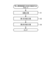
- FIG. 4 is a flow chart showing an example of the steps of the method for producing a rare earth sintered magnet alloy according to the third embodiment.
- the method for producing a rare earth sintered magnet alloy which is the raw material for the rare earth sintered magnet 1
- a melting step S1 in which the raw material for the rare earth sintered magnet alloy, which contains the elements that make up the rare earth sintered magnet 1 is heated to a temperature of 1000K or higher to melt it
- step S2 a first cooling step
- step S3 in which the molten raw material is cooled on a rotating body to obtain
- the raw material of the rare earth sintered magnet alloy is heated to a temperature of 1000K or higher in a crucible in an atmosphere containing an inert gas such as Ar (argon) or in a vacuum to melt it.
- the raw materials can be Nd, Pr, RH, R, Fe, B, and M.
- RH can be one or more elements of Dy and Tb.
- M can be one or more elements selected from the group of Ga, Al, Cu, and Co.
- FeB can also be used as a raw material instead of B.
- the molten alloy prepared in the melting step is poured into a tundish and then onto a single roll, which is a rotating body.
- the molten alloy is rapidly cooled on the single roll rotating in a specified direction, and a solidified alloy having a thickness thinner than the ingot alloy is prepared from the molten alloy on the single roll.
- a single roll is used as the rotating body, but this is not limited thereto, and the molten alloy may be rapidly cooled by contacting it with a twin roll, a rotating disk, a rotating cylindrical mold, or the like.
- the cooling rate in the first cooling step is preferably 10° C./sec or more and 10 7 ° C./sec or less, and more preferably 10 3 ° C./sec or more and 10 4 ° C./sec or less.
- the thickness of the solidified alloy is in the range of 0.03 mm or more and 10 mm or less.
- the thin solidified alloy prepared in the first cooling step is put into a tray container and cooled.
- the thin solidified alloy is broken into flake-like rare earth sintered magnet alloy when it enters the tray container and cooled.
- a ribbon-like rare earth sintered magnet alloy may be obtained, and is not limited to flake-like.
- the cooling rate in the second cooling step is preferably 10-2 °C/sec or more and 105 °C/sec or less, and more preferably 10-1 °C/sec or more and 102 °C/sec or less.
- the rare earth sintered magnet alloy obtained through these processes has a minor axis size of 3 ⁇ m or more and 10 ⁇ m or less, and a major axis size of 10 ⁇ m or more and 300 ⁇ m or less.
- the rare earth sintered magnet alloy has a fine crystalline structure containing a (Nd, Pr, RH, La, Sm)-Fe-B crystal phase containing element M as a trace component, and a crystalline subphase 20 of an oxide represented by (Nd, Pr, RH, La, Sm)-O containing element M as a trace component.
- the (Nd, Pr, RH, La, Sm)-Fe-B crystal phase containing the element M as a trace component is also referred to as the (Nd, Pr, RH, La, Sm)-Fe-B crystal phase
- the oxide crystalline subphase 20 represented by (Nd, Pr, RH, La, Sm)-O containing the element M as a trace component is also referred to as the (Nd, Pr, RH, La, Sm)-O phase.
- the (Nd, Pr, RH, La, Sm)-O phase is a non-magnetic phase consisting of an oxide having a relatively high concentration of rare earth elements.
- the thickness of the (Nd, Pr, RH, La, Sm)-O phase corresponds to the width of the grain boundary and is 10 ⁇ m or less.
- the rare earth sintered magnet alloy manufactured by the above manufacturing method has a finer structure than the rare earth sintered magnet alloy obtained by the mold casting method because it has been subjected to a rapid cooling process.
- FIG. 5 is a flow chart showing an example of the procedure of the method for manufacturing the rare earth sintered magnet according to the third embodiment.
- the method for manufacturing the rare earth sintered magnet 1 includes a crushing step (step S21) for crushing a rare earth sintered magnet alloy having a (Nd, Pr, RH, La, Sm)-Fe-B crystal phase and a (Nd, Pr, RH, La, Sm)-O phase, a molding step (step S22) for preparing a compact by molding the powder of the crushed rare earth sintered magnet alloy, a sintering step (step S23) for sintering the compact at a sintering temperature that is a set temperature to obtain a sintered body, an aging step (step S24) for aging the sintered body to enhance the magnetic properties such as the coercive force of the rare earth sintered magnet 1, and a cooling step (step S21) for crushing a rare earth sintered magnet alloy having a (Nd, Pr, RH, La, Sm)-
- the rare earth sintered magnet alloy having the (Nd, Pr, RH, La, Sm)-Fe-B crystal phase and the (Nd, Pr, RH, La, Sm)-O phase manufactured according to the manufacturing method of the rare earth sintered magnet alloy of FIG. 4 is pulverized to obtain a rare earth sintered magnet alloy powder having a particle size of 200 ⁇ m or less, preferably 0.5 ⁇ m to 100 ⁇ m, and further, when considering magnetization performance, about 1 ⁇ m to 10 ⁇ m.
- the rare earth sintered magnet alloy is pulverized using an agate mortar, a stamp mill, a jaw crusher, or a jet mill.
- the rare earth sintered magnet alloy when the particle size of the powder is to be reduced, it is preferable to pulverize the rare earth sintered magnet alloy in an atmosphere containing an inert gas.
- the rare earth sintered magnet alloy By pulverizing the rare earth sintered magnet alloy in an atmosphere containing an inert gas, the incorporation of oxygen into the powder can be suppressed.
- the atmosphere during pulverization does not affect the magnetic properties of the magnet, the rare earth sintered magnet alloy may be pulverized in air.
- the La and Sm of the rare earth sintered magnet alloy used in manufacturing the rare earth sintered magnet 1 of embodiment 2 can be replaced with a rare earth element R other than Nd, Pr and the heavy rare earth element RH.
- a rare earth sintered magnet alloy having a (Nd, Pr, RH, R)-Fe-B crystal phase and a (Nd, Pr, RH, R)-O phase may be pulverized.
- the rare earth sintered magnet alloy powder is compression molded in a die to which a magnetic field is applied to prepare a molded body.
- the magnetic field applied can be 2 T, for example. Note that molding can also be performed without applying a magnetic field, rather than in a magnetic field.
- the compression-molded body is held at a sintering temperature in the range of 950°C to 1300°C, preferably 1000°C to less than 1150°C, for a time in the range of 0.1 to 10 hours, preferably 1.0 to 6.0 hours, to obtain a sintered body.
- Sintering is preferably performed in an atmosphere containing an inert gas or in a vacuum to suppress oxidation. Sintering may be performed while a magnetic field is applied.
- the aging process of step S24 includes a first aging process of step S24-1, a second aging process of step S24-2, a third aging process of step S24-3, and a fourth aging process of step S24-4.
- Aging is preferably performed in an atmosphere containing an inert gas or in a vacuum to suppress oxidation.
- the obtained sintered body is held at a first aging temperature, which is a temperature lower than the sintering temperature, specifically within the range of 700°C or higher and lower than 950°C, for 0.1 to 10 hours, preferably 0.5 to 5 hours.
- a first aging temperature which is a temperature lower than the sintering temperature, specifically within the range of 700°C or higher and lower than 950°C, for 0.1 to 10 hours, preferably 0.5 to 5 hours.
- the sintered body held in the first aging process is held at a second aging temperature that is lower than the first aging temperature, specifically within the range of 450°C or higher and lower than 700°C, for 0.1 to 10 hours, preferably 1.0 to 7 hours.
- the sintered body held in the second aging process is heated again to the first aging temperature, specifically to a temperature in the range of 700°C or higher and lower than 950°C, and held at the first aging temperature for 0.1 hours to 10 hours, preferably 0.5 hours to 5 hours.
- the sintered body held in the third aging process is again held at the second aging temperature, specifically within the range of 450°C or higher and lower than 700°C, for 0.1 to 10 hours, preferably 1.0 to 7 hours.
- the sintered body held in the fourth aging step is held at a temperature lower than the second aging temperature, specifically, in the range of 200°C or higher and lower than 450°C for 0.1 to 5 hours.
- the rare earth sintered magnet 1 is then completed by cooling to room temperature. It is preferable that the cooling is also performed in an atmosphere containing an inert gas or in a vacuum to suppress oxidation.
- the sintered body is repeatedly maintained in the temperature range of the unstable energy state.
- the first main phase 11 consisting of CNd>CPr
- the second main phase 12 consisting of CNd ⁇ CPr
- the rare earth sintered magnet 1 has two main phases 10, the first main phase 11 and the second main phase 12, and when focusing on the cores 11c and 12c of the two main phases 10, the first main phase 11 has a higher sum of the concentration of Nd and the concentration of the heavy rare earth element RH than the concentration of Pr, and conversely, the second main phase 12 has a higher concentration of Pr than the sum of the concentration of Nd and the concentration of the heavy rare earth element RH.
- a rare earth sintered magnet 1 which has a crystalline first subphase 21 whose main component is an oxide phase expressed as (Nd, Pr, RH, La, Sm)-O containing the element M as a trace component, and a crystalline second subphase 22 whose main component is an oxide phase expressed as (Nd, Pr, RH, La)-O containing the element M as a trace component, in which the first subphase 21 has a higher Sm concentration than the second subphase 22, and the second subphase 22 has a higher M concentration than the first subphase 21.
- a crystalline first subphase 21 mainly composed of an oxide phase represented by (Nd, Pr, RH, La, Sm)-O and a crystalline second subphase 22 mainly composed of an oxide phase represented by (Nd, Pr, RH, La)-O are generated from the (Nd, Pr, RH, La)-O phase, depending on the concentration of element M, for example.
- the second subphase 22 may contain a small amount of Sm.
- the concentration of Sm in the first subphase 21 is higher than that of the second subphase 22, it can be said that the first subphase 21 forms an Sm-enriched portion in the subphase 20.
- the high concentration portion 41 of the first subphase 21 forms an Sm-enriched portion.
- a rare earth sintered magnet alloy having a (Nd, Pr, RH, La, Sm)-Fe-B crystal phase and a (Nd, Pr, RH, La, Sm)-O phase is pulverized to produce a rare earth sintered magnet alloy powder, the shaped compact is sintered to form a sintered body, and the sintered body is then aged to produce a rare earth sintered magnet 1. This makes it possible to produce a rare earth sintered magnet 1 having the structure described in the second embodiment.
- the heavy rare earth element RH is adjusted to a desired concentration before producing a rare earth sintered magnet alloy, and the rare earth sintered magnet 1 is produced using this rare earth sintered magnet alloy, so that the heavy rare earth element RH can easily enter the inside of the main phase 10.
- the temperature and time in the sintering step, the aging step, and the cooling step are controlled.
- the obtained sintered body in the first aging step, is held at the first aging temperature, which is a temperature lower than the sintering temperature, specifically within the range of 700°C to less than 950°C, for 0.1 to 10 hours, preferably 0.5 to 5 hours.
- the sintered body is held at the second aging temperature, which is a temperature lower than the first aging temperature, specifically within the range of 450°C to less than 700°C, for 0.1 to 10 hours, preferably 1.0 to 7 hours.
- the temperature is raised again to the first aging temperature, specifically within the range of 700°C to less than 950°C, and the sintered body is held at the first aging temperature for 0.1 to 10 hours, preferably 0.5 to 5 hours.
- the sintered body is again held at the second aging temperature, specifically, within a range of 450°C to 700°C for 0.1 to 10 hours, preferably 1.0 to 7 hours. In this way, the temperature and time are controlled so that the first aging step and the second aging step are performed in two sets. This creates a state in which the sintered body is repeatedly held in a temperature range of an unstable energy state.
- the rare earth sintered magnet 1 has two types of main phases 10, a first main phase 11 and a second main phase 12.
- a rare earth sintered magnet 1 having a characteristic structure in which a crystalline first subphase 21 mainly comprises an oxide phase represented by (Nd, Pr, RH, La, Sm)-O containing the element M as a trace component, and a crystalline second subphase 22 mainly comprises an oxide phase represented by (Nd, Pr, RH, La)-O containing the element M as a trace component, and the first subphase 21 has a higher Sm concentration than the second subphase 22, and the second subphase 22 has a higher element M concentration than the first subphase 21.
- the Sm concentration of the first subphase 21 is higher than that of the second subphase 22 in the subphase 20, it is possible to manufacture a rare earth sintered magnet 1 having a characteristic structure in which it has an Sm-enriched portion, i.e., the first subphase 21 in which Sm is enriched.
- the first subphase 21 has a high-concentration portion 41 with a high Sm concentration and a low-concentration portion 42 with a low Sm concentration, it is possible to produce a rare earth sintered magnet 1 having a characteristic structure in which the high-concentration portion 41 is an Sm-enriched portion.
- the R-T-B based sintered magnet described in Patent Document 1 has one or more rare earth elements, with the heavy rare earth element RH being essential, and has one type of main phase particle composed of a core portion and a shell portion.
- all main phase particles contain the heavy rare earth element RH.
- the main phase 10 of the rare earth sintered magnet 1 according to embodiment 1 is a mixture of a first main phase 11 in which the heavy rare earth element RH is contained in the core portion 11c, and a second main phase 12 in which the heavy rare earth element RH is hardly contained in the core portion 12c.
- the heavy rare earth element RH is selectively arranged in the first main phase 11 of one of the two types of main phases 10.
- the rare earth sintered magnet 1 according to embodiment 1, in which the heavy rare earth element RH only needs to be contained in the first main phase 11 of the two types of main phases 10, can reduce the amount of heavy rare earth element RH used.
- the ratio of the volume of the subphase 20 to the total volume of the rare earth sintered magnet 1 is extremely small, even if the heavy rare earth element RH is diffused and present in the subphase 20, the amount of heavy rare earth element RH used can be reduced compared to the technology of Patent Document 1.
- FIG. 6 is a cross-sectional view showing a schematic example of the configuration of a rotor equipped with a rare earth sintered magnet according to embodiment 4.
- Fig. 6 shows a cross section in a direction perpendicular to the rotation axis RA of the rotor 100.
- the rotor 100 is rotatable about the rotation axis RA.
- the rotor 100 includes a rotor core 101 and rare earth sintered magnets 1 that are inserted into magnet insertion holes 102 provided in the rotor core 101 along the circumferential direction of the rotor 100.
- FIG. 6 shows an example in which four magnet insertion holes 102 are provided in the rotor core 101 and four rare earth sintered magnets 1 are inserted into the magnet insertion holes 102, but the number of magnet insertion holes 102 and rare earth sintered magnets 1 may be changed depending on the design of the rotor 100.
- the rotor core 101 is formed by stacking multiple disc-shaped electromagnetic steel plates in the axial direction of the rotation axis RA.
- the rare earth sintered magnets 1 are manufactured according to the manufacturing method described in embodiment 3.
- the four rare earth sintered magnets 1 are inserted into the corresponding magnet insertion holes 102.
- the four rare earth sintered magnets 1 are each magnetized so that the magnetic poles of the rare earth sintered magnets 1 on the radial outside of the rotor 100 are different between adjacent rare earth sintered magnets 1.
- the rotor 100 according to the fourth embodiment includes the rare earth sintered magnet 1 according to the first or second embodiment, which can improve the magnetic properties at room temperature and suppress the deterioration of the magnetic properties with increasing temperature.
- the rare earth sintered magnet 1 according to the first or second embodiment is a rare earth sintered magnet 1 that suppresses the use of heavy rare earth elements RH compared to the conventional one and can suppress the deterioration of the magnetic properties with increasing temperature while maintaining high residual magnetic flux density and coercive force, so that the deterioration of the magnetic properties is suppressed even in a high temperature environment exceeding 100°C.
- the magnetic properties and magnetization are improved, and the operation of the rotor 100 can be stabilized even in a high temperature environment exceeding 100°C. Furthermore, since the rare earth sintered magnet 1 according to the first or second embodiment has a better magnetization performance than the conventional one, it is possible to magnetize the rotor 100 in an assembled state in which the rare earth sintered magnet 1 is set, which makes it easier to handle the manufacturing process. Furthermore, the magnetization process can be performed with reduced voltage, which contributes to energy savings.
- FIG. 7 is a cross-sectional view showing a schematic example of a configuration of a rotating machine according to the fifth embodiment.
- Fig. 7 shows a cross section in a direction perpendicular to the rotation axis RA of the rotor 100.
- the rotating machine 120 includes a rotor 100 rotatable about the rotation axis RA described in the fourth embodiment, and an annular stator 130 arranged coaxially with the rotor 100 and facing the rotor 100.
- the stator 130 is formed by laminating a plurality of electromagnetic steel sheets in the axial direction of the rotation axis RA.
- the configuration of the stator 130 is not limited to this, and an existing configuration can also be adopted.
- the stator 130 has teeth 131 protruding toward the rotor 100 and arranged along the inner surface of the stator 130.
- the teeth 131 are provided with windings 132.
- the windings 132 may be wound in a concentrated winding or a distributed winding, for example.
- the stator 130 has windings 132 attached to the teeth 131 protruding toward the rotor 100 on the inner surface on the side where the rotor 100 is arranged, and has an annular structure arranged facing the rotor 100.
- the number of magnetic poles of the rotor 100 in the rotating machine 120 must be two or more, that is, the number of rare earth sintered magnets 1 must be two or more.
- FIG. 7 shows an example of a rotor 100 with embedded magnets
- the rotor 100 may be a surface magnet type rotor in which the rare earth sintered magnets 1 are fixed to the outer periphery with adhesive.
- the rotating machine 120 in embodiment 5 includes the rare earth sintered magnet 1 according to embodiment 1 or 2, which can improve the magnetic properties at room temperature and suppress the deterioration of the magnetic properties with increasing temperature.
- the rare earth sintered magnet 1 according to embodiment 1 or 2 is a rare earth sintered magnet 1 that suppresses the use of heavy rare earth elements RH compared to conventional magnets and can suppress the deterioration of the magnetic properties with increasing temperature while maintaining high residual magnetic flux density and coercive force, so that the deterioration of the magnetic properties is suppressed even in a high-temperature environment exceeding 100°C.
- the magnetic properties and magnetization are improved while replacing Nd and heavy rare earth elements RH, which are expensive, highly unevenly distributed in different regions, and have procurement risks, with inexpensive rare earth elements, and the rotor 100 can be stably driven and the operation of the rotating machine 120 can be stabilized even in a high-temperature environment exceeding 100°C.
- rare earth sintered magnet 1 is manufactured by the method shown in embodiment 3 using a sample represented by the (Nd, Pr, Tb, La, Sm)-Fe-B crystal phase containing element M as a trace component of a plurality of rare earth sintered magnet alloys having different compositions and the (Nd, Pr, Tb, La, Sm)-O phase containing element M as a trace component.
- rare earth sintered magnet 1 is manufactured by using a rare earth sintered magnet alloy with a changed content of Nd, Pr, Tb, La and Sm.
- rare earth sintered magnet 1 is manufactured by using a manufacturing method shown in embodiment 3 using a rare earth sintered magnet alloy containing the (Nd, Pr, Tb, La, Sm)-Fe-B crystal phase containing element M as a trace component and the (Nd, Pr, Tb, La, Sm)-O phase containing element M as a trace component.
- M is one or more elements selected from the group of Ga, Al, Cu, and Co, but here we will take the example where M is Co.
- rare earth sintered magnet 1 is experimentally manufactured using samples of multiple rare earth sintered magnet alloys with different compositions, represented by R-Fe-B-M, by a general rare earth magnet manufacturing method such as that shown in Patent Document 1 or Patent Document 2.
- R-Fe-B-M a general rare earth magnet manufacturing method
- Patent Document 2 a general rare earth magnet manufacturing method
- a rare earth sintered magnet 1 is manufactured using the manufacturing method shown in Patent Document 1 from a rare earth sintered magnet alloy in which R is Nd, or a rare earth sintered magnet alloy in which R includes Nd and one or more elements selected from the group of Pr, Tb, La, and Sm, and M includes one or more elements selected from the group of Ga, Al, Cu, and Co.
- M is Co.
- Comparative Example 2 uses (Nd, Tb)-Fe-B, which does not include element M
- Comparative Example 3 uses Nd-Fe-B-M, which does not include rare earth elements R other than Nd.
- a rare earth sintered magnet 1 is manufactured using the manufacturing method shown in Patent Document 2 from a rare earth sintered magnet alloy in which R is Nd, or a rare earth sintered magnet alloy in which R includes Nd and one or more elements selected from the group of Pr, Tb, La, and Sm, and M includes one or more elements selected from the group of Ga, Al, Cu, and Co.
- M is Co.
- Nd-Fe-B-M is used, which does not include rare earth elements R other than Nd
- Comparative Example 12 Nd-Fe-B is used, which does not include rare earth elements R other than Nd and element M.
- the manufacturing method shown in Patent Document 2 includes a step of performing hot working on the sintered body.
- Table 3 shows the general formula of the rare earth sintered magnets of the examples and comparative examples, the content of the elements constituting R, the analysis results of the structural morphology, and the evaluation results of the magnetic properties and magnetization performance.
- Table 3 shows the general formula of the main phase 10 of each sample, which is the rare earth sintered magnet 1 of Examples 1 to 8 and Comparative Examples 1 to 18.
- the structure of the rare earth sintered magnet 1 is determined by elemental analysis using a scanning electron microscope (SEM) and an EPMA.
- SEM scanning electron microscope
- EPMA FE-EPMA (manufactured by JEOL Ltd., product name: JXA-8530F) is used as the SEM and EPMA.
- the conditions for the elemental analysis are an acceleration voltage of 15.0 kV, an irradiation current of 2.271e -008 A, an irradiation time of 130 ms, a pixel count of 512 pixels x 512 pixels, a magnification of 5000 times, and an accumulation count of 1 time.
- the magnetic properties are evaluated by measuring the coercive force of multiple samples using a pulse excitation type BH tracer.
- the maximum magnetic field applied by the BH tracer is 6 T or more, at which the rare earth sintered magnet 1 is fully magnetized.
- a DC magnetic flux meter also called a DC type BH tracer
- VSM vibrating sample magnetometer
- MPMS magnetic property measurement system
- PPMS physical property measurement system
- the measurement is performed in an atmosphere containing an inert gas such as nitrogen.
- the magnetic properties of each sample are measured by detecting the magnetization picked up by a search coil or a magnetic sensor from the rare earth sintered magnet 1 magnetized by the applied magnetic field.
- the magnetic properties are measured from the J-H curve or B-H curve, which is the measured magnetic hysteresis.
- the magnetic properties of each sample are measured at a first measurement temperature T1 and a second measurement temperature T2, which are different from each other.
- the temperature coefficient ⁇ [%/°C] of the residual magnetic flux density is the ratio of the difference between the residual magnetic flux density at the first measurement temperature T1 and the residual magnetic flux density at the second measurement temperature T2 to the residual magnetic flux density at the first measurement temperature T1, divided by the temperature difference (T2-T1).
- the temperature coefficient ⁇ [%/°C] of the coercive force is the ratio of the difference between the coercive force at the first measurement temperature T1 and the coercive force at the second measurement temperature T2 to the coercive force at the first measurement temperature T1, divided by the temperature difference (T2-T1). Therefore, the smaller the absolute values
- magnetization performance can be measured by calculating the magnetization rate from the ratio of the magnetic flux density measured from the magnetic hysteresis drawn by applying an arbitrary magnetic field at a constant permeance coefficient to the magnetic flux density measured from the magnetic hysteresis drawn by applying a saturating magnetic field. If a high magnetization rate can be obtained even in a weaker magnetic field, it can be said that the magnetization performance is high.
- FIG. 8 is a trace of the composition image obtained by analyzing the cross section of the rare earth sintered magnet from Examples 1 to 8 with FE-EPMA.
- FIG. 9 to FIG. 15 are elemental mappings obtained by analyzing the cross section of the rare earth sintered magnet from Examples 1 to 8 with FE-EPMA.
- FIG. 9 is elemental mapping of Nd
- FIG. 10 is elemental mapping of Pr
- FIG. 11 is elemental mapping of Tb
- FIG. 12 is elemental mapping of Co
- FIG. 13 is elemental mapping of O
- FIG. 14 is elemental mapping of Sm
- FIG. 15 is elemental mapping of La. Note that FIG. 9 to FIG.
- FIG. 8 to FIG. 15 show representative examples from Examples 1 to 8. Furthermore, the same components as those in Figures 1 and 2 are given the same reference numerals.
- the main phase 10 including crystal grains based on the Nd 2 Fe 14 B crystal structure of the rare earth sintered magnet 1, in which RH is Tb and R is one or more rare earth elements selected from among Nd, Pr, and RH and the general formula (Nd, Pr, Tb, R)-Fe-B- M is included, has cores 11c and 12c and shells 11s and 12s that cover the cores 11c and 12c.
- the main phase 10 includes a first main phase 11 in which CNd>CPr and a second main phase 12 in which CNd ⁇ CPr are mixed. It can also be confirmed that when the concentration of Tb in the first main phase 11 is C1Tb and the concentration of Tb in the second main phase 12 is C2Tb, C1Tb>C2Tb.
- the concentration difference shown here between "the first main phase 11 where CNd>CPr and the second main phase 12 where CNd ⁇ CPr” means that a clear difference has been found between the detection intensity of Nd and the detection intensity of Pr by mapping analysis using EPMA.
- the Nd concentration in the core portion 11c has a higher than average detection intensity by EPMA
- the Pr concentration has a lower than average detection intensity by EPMA, which in this case indicates that the concentration is close to the lower limit.
- the second main phase 12 is the opposite of the case of the first main phase 11.
- the average EPMA Nd detection level is 89, and the average Pr detection level is 46.
- the first main phase 11 CNd is higher than 89, and CPr is near the lower limit, indicating a clear concentration difference.
- the second main phase 12 is the opposite of the first main phase 11, and therefore CPr is higher than 46, and CNd is near the lower limit, indicating a clear concentration difference.
- the concentration difference shown by "C1Tb>C2Tb” means that mapping analysis using EPMA has revealed a clear difference between the detection intensity of Tb in the first main phase 11 and the detection intensity of Tb in the second main phase 12. Specifically, the EPMA detection intensity of the Tb concentration in the first main phase 11 is higher than the average, while the EPMA detection intensity of the Tb concentration in the second main phase 12 is lower than the average, in this case showing the vicinity of the lower limit.
- the average EPMA Tb detection level is 44.
- CTb is higher than 44, but in the case of the second main phase 12, CTb is near the lower limit, and a clear concentration difference occurs.
- the rare earth sintered magnet 1 has, in addition to the first main phase 11 and second main phase 12 in embodiment 1, a crystalline first subphase 21 mainly composed of an oxide phase expressed as (Nd, Pr, Tb, La, Sm)-O containing the element M as a trace component, and a crystalline second subphase 22 mainly composed of an oxide phase expressed as (Nd, Pr, Tb, La)-O containing the element M as a trace component. It can also be confirmed that the concentration of Sm is higher in the first subphase 21 than in the second subphase 22, and the concentration of Co, which is the element M, is higher in the second subphase 22 than in the first subphase 21.
- the concentration of Nd and the concentration of Tb indicate that the detection intensity by EPMA is higher than the average, and the concentration of Pr indicates that the detection intensity by EPMA is lower than the average, in this case near the lower limit.
- the concentration of Pr indicates that the detection intensity by EPMA is lower than the average, in this case near the lower limit.
- the concentration of the second main phase 12 it can be said that the situation is the opposite to that of the first main phase 11.
- the difference in concentration of Sm between the first subphase 21 and the second subphase 22 means that the detection intensity of Sm is higher on average in the first subphase 21 than in the second subphase 22 by mapping analysis using EPMA.
- the average EPMA detection level of Sm is 15.0
- the first subphase 21 is higher than 15.0
- the second subphase 22 is lower than 15.0, that is, the Sm is in an aggregated state and cannot be detected.
- the difference in concentration of Co, which is element M between the first subphase 21 and the second subphase 22 means that the detection intensity of Co is higher on average in the second subphase 22 than in the first subphase 21 by mapping analysis using EPMA.
- the average EPMA Co detection level is 31.8
- the second subphase 22 is higher than 31.8
- the first subphase 21 is lower than 31.8, meaning that the two are in an aggregated state and cannot be detected.
- the intensity ratio of element mapping obtained by FE-EPMA analysis it can be confirmed that there are more first main phases 11 where C(Nd, RH)>CPr than the number of second main phases 12 where C(Nd, RH) ⁇ CPr.
- the first main phase 11 satisfies the relational expressions CNd>SNd, CPr ⁇ SPr, CTb>STb
- the second main phase 12 satisfies the relational expressions CNd ⁇ SNd, CPr>SPr, CTb ⁇ STb.
- the shape of each sample used for magnetic measurement is a block shape with length, width and height all being 7 mm.
- the first measurement temperature T1 is 23°C
- the second measurement temperature T2 is 200°C.
- 23°C is room temperature.
- the second measurement temperature T2 of 200°C is a temperature that can occur in the operating environment of automotive motors and industrial motors.
- the residual magnetic flux density and coercivity of each sample from Examples 1 to 8 and Comparative Examples 2 to 18 are judged in comparison with Comparative Example 1. If the residual magnetic flux density and coercivity values at 23°C of each sample are within 1%, which is considered to be the measurement error, compared to the values in Comparative Example 1, they are judged as "same.” If they are 1% or more higher, they are judged as “good.” If they are 1% or less lower, they are judged as "poor.”
- the temperature coefficient ⁇ of the residual magnetic flux density is calculated using the residual magnetic flux density at the first measurement temperature T1 of 23°C and the residual magnetic flux density at the second measurement temperature T2 of 200°C.
- the temperature coefficient ⁇ of the coercivity is calculated using the coercivity at the first measurement temperature T1 of 23°C and the coercivity at the second measurement temperature T2 of 200°C.
- the temperature coefficients of the residual magnetic flux density and the temperature coefficients of the coercivity in each sample according to Examples 1 to 8 and Comparative Examples 2 to 18 are judged by comparing with Comparative Example 1.
- the magnetization performance is calculated from the ratio of the magnetic flux density at the intersection of the magnetic hysteresis and the permeance coefficient Pc of an applied magnetic field of 20 kOe to the magnetic flux density at the intersection of the magnetic hysteresis and the permeance coefficient Pc of an applied magnetic field of 80 kOe, which is the saturated magnetization state.
- the magnetization performance of each sample from Examples 1 to 8 and Comparative Examples 2 to 18 is judged by comparing it with Comparative Example 1.
- Comparative Example 1 is a sample of rare earth sintered magnet 1 produced according to the manufacturing method described in Patent Document 1 using Nd, Tb, Fe, FeB, and Co as element M as raw materials so as to obtain (Nd, Tb)-Fe-B-M.
- the remanence B r is 1.25 T and the coercivity H cJ is 1650 kA/m.
- the temperature coefficients of the residual magnetic flux density and the coercivity are
- 0.185%/° C. and
- 0.455%/° C., respectively.
- the magnetization rate is 98.6%.
- Comparative example 2 is a sample of rare earth sintered magnet 1 produced according to the manufacturing method described in Patent Document 1 using Nd, Tb, Fe, and FeB as raw materials so as to obtain (Nd, Tb)-Fe-B.
- Co which is element M
- Comparative example 2 is a sample of rare earth sintered magnet 1 produced according to the manufacturing method described in Patent Document 1 using Nd, Tb, Fe, and FeB as raw materials so as to obtain (Nd, Tb)-Fe-B.
- Co which is element M
- Comparative example 3 is a sample of rare earth sintered magnet 1 produced according to the manufacturing method described in Patent Document 1 using Nd, Fe, and FeB, and further Co, which is element M, as raw materials so as to obtain Nd-Fe-B-M.
- Nd, Fe, and FeB, and further Co which is element M, as raw materials so as to obtain Nd-Fe-B-M.
- Pr, La, and Sm are not added, a core-shell structure in the main phase 10 cannot be confirmed, and it cannot be confirmed that the concentration of Sm in the subphase 20 is higher in the first subphase 21 than in the second subphase 22. Furthermore, it cannot be confirmed that the concentration of Co is higher in the second subphase 22 than in the first subphase 21.
- Comparative example 4 is a sample of rare earth sintered magnet 1 produced according to the manufacturing method described in Patent Document 1 using Nd, Pr, Fe, FeB, and Co as element M as raw materials so as to obtain (Nd, Pr)-Fe-B-M.
- Nd, Pr Pr
- FeB Fe
- Co element M
- the structural form of this sample is observed according to the above-mentioned method, it is confirmed that Nd and Pr are mixed in main phase 10 due to the addition of Pr, but a core-shell structure is not formed.
- La and Sm are not added, it is not possible to confirm that the concentration of Sm in subphase 20 is higher in first subphase 21 than in second subphase 22. Furthermore, it is not possible to confirm that the concentration of Co is higher in second subphase 22 than in first subphase 21.
- Comparative example 5 is a sample of rare earth sintered magnet 1 produced according to the manufacturing method described in Patent Document 1 using Nd, Pr, Tb, Fe, FeB, and Co as element M as raw materials so as to obtain (Nd, Pr, Tb)-Fe-B-M.
- Nd, Pr, Tb Nd, Pr, Tb
- Fe, FeB Co as element M as raw materials so as to obtain (Nd, Pr, Tb)-Fe-B-M.
- a main phase 10 in which Nd and Pr are mixed can be confirmed, but a core-shell structure is not formed.
- La and Sm are not added, it cannot be confirmed that the concentration of Sm in the subphase 20 is higher in the first subphase 21 than in the second subphase 22. Furthermore, it cannot be confirmed that the concentration of Co is higher in the second subphase 22 than in the first subphase 21.
- the residual magnetic flux density and coercive force are improved by adding Pr and Tb, which is a heavy rare earth element RH, and the residual magnetic flux density is "same" and the coercive force is "good".
- the temperature coefficient of coercivity which is a characteristic of Pr, deteriorates to "poor.” Because the manufacturing method does not include hot working, the magnetization performance is “equal or better.” The temperature coefficient of residual magnetic flux density is “equal.” This reflects the fact that although the addition of Tb, Pr, and Co increases the magnetic anisotropy of the main phase 10 and improves the coercivity, it is not the optimal structural form of the main phase 10 and subphase 20.
- Comparative Example 6 is a sample of rare earth sintered magnet 1 produced according to the manufacturing method described in Patent Document 1 using Nd, La, Sm, Fe, FeB, and Co as element M as raw materials so as to obtain (Nd, La, Sm)-Fe-B-M.
- Nd, La, Sm element M
- the core-shell structure of the main phase 10 cannot be confirmed because Pr is not added.
- the concentration of Sm is segregated to one subphase 20 due to the segregation of La, but the second subphase 22 does not exist.
- the concentration of Sm is higher in the first subphase 21 than in the second subphase 22, and it cannot be confirmed that the concentration of Co is higher in the second subphase 22 than in the first subphase 21.
- the residual magnetic flux density is "good” because Tb, which is a heavy rare earth element RH, is not included, but the coercivity is significantly lower than that of Comparative Example 1, and is therefore "poor.”
- the temperature coefficient of the residual magnetic flux density and the temperature coefficient of the coercivity are "good” because La and Sm are added and La and Sm are present in the main phase 10 or subphase 20.
- the magnetization performance is "equal to or better" because the manufacturing method does not include hot working. This is a result that reflects the fact that the temperature coefficient of the coercivity shows good results due to the presence of La and Sm in the main phase 10 or subphase 20, but the magnetic properties at room temperature do not improve, and that the structure in the main phase 10 and subphase 20 is not optimal.
- Comparative example 7 is a sample of rare earth sintered magnet 1 produced according to the manufacturing method described in Patent Document 1 using Nd, La, Sm, Fe, FeB, and Co as element M as raw materials so as to obtain (Nd, La, Sm)-Fe-B-M.
- the composition ratio of Nd, La, and Sm is different from that of comparative example 6.
- the core-shell structure of the main phase 10 cannot be confirmed because Pr is not added.
- the concentration of Sm is segregated in one subphase 20 due to the segregation of La, but the second subphase 22 does not exist.
- Comparative Example 8 is a sample of rare earth sintered magnet 1 produced according to the manufacturing method described in Patent Document 1 using Nd, Pr, La, Sm, Fe, FeB, and Co as element M as raw materials so as to obtain (Nd, Pr, La, Sm)-Fe-B-M.
- Nd, Pr, La, Sm element M
- the main phase 10 in which Nd and Pr are mixed can be confirmed due to the addition of Pr, but a core-shell structure is not formed.
- the concentration of Sm is segregated in one subphase 20 due to the segregation of La, but the second subphase 22 does not exist.
- the concentration of Sm is higher in the first subphase 21 than in the second subphase 22, and it cannot be confirmed that the concentration of Co is higher in the second subphase 22 than in the first subphase 21.
- the remanence is "good” because it does not contain Tb, a heavy rare earth element RH, but the addition of La, Sm, and Pr does not improve the coercivity to the same extent as when Tb is added, so the coercivity is "poor.”
- the temperature coefficient of the remanence and the temperature coefficient of the coercivity should be "good,” but the addition of Pr worsens the temperature coefficient of the coercivity, which is a characteristic of Pr, so only the temperature coefficient of the coercivity is reduced to the "same.” Since the manufacturing method does not include hot working, the magnetization performance is "same or better.”
- Comparative Example 9 is a sample of rare earth sintered magnet 1 produced according to the manufacturing method described in Patent Document 1 using Nd, Pr, Tb, La, Sm, Fe, FeB, and Co as element M as raw materials so as to obtain (Nd, Pr, Tb, La, Sm)-Fe-B-M.
- Nd, Pr, Tb, La, Sm element M
- the main phase 10 in which Nd and Pr are mixed can be confirmed due to the addition of Pr, but a core-shell structure is not formed.
- the concentration of Sm is segregated in one subphase 20 due to the segregation of La, but the second subphase 22 does not exist.
- Comparative example 10 is a sample of rare earth sintered magnet 1 produced according to the manufacturing method including hot working described in Patent Document 2 using Nd, Tb, Fe, FeB, and Co as element M as raw materials so as to obtain (Nd, Tb)-Fe-B-M.
- the temperature coefficient of the residual magnetic flux density is "same.” This reflects the fact that, although the absolute value of the coercive force and the temperature coefficient of the coercive force have improved as the magnetic powder has been refined through hot working, it is difficult to align the magnetic moment, resulting in a decrease in the residual magnetic flux density and a deterioration in the magnetization performance.
- Comparative Example 11 is a sample of rare earth sintered magnet 1 produced according to the manufacturing method including hot processing described in Patent Document 2 using Nd, Fe, and FeB, and further Co as element M, as raw materials so as to obtain Nd-Fe-B-M.
- the core-shell structure in the main phase 10 cannot be confirmed, and it cannot be confirmed that the concentration of Sm in the subphase 20 is higher in the first subphase 21 than in the second subphase 22. Furthermore, it cannot be confirmed that the concentration of Co is higher in the second subphase 22 than in the first subphase 21.
- the residual magnetic flux density does not drop significantly and is at the same level as Comparative Example 1, so the residual magnetic flux density is "same.”
- the temperature coefficient of the residual magnetic flux density is "same.” This reflects the deterioration of magnetization performance due to the difficulty in aligning the magnetic moment, although the coercivity is improved as the magnetic powder is refined by hot working.
- Comparative Example 12 is a sample of rare earth sintered magnet 1 produced according to the manufacturing method including hot working described in Patent Document 2 using Nd, Fe, and FeB as raw materials to produce Nd-Fe-B.
- Co which is element M
- Comparative Example 12 Co, which is element M, is not added.
- Pr, La, and Sm are not added, a core-shell structure in the main phase 10 cannot be confirmed, and it cannot be confirmed that the concentration of Sm in the subphase 20 is higher in the first subphase 21 than in the second subphase 22.
- Co since Co is not added, it cannot be confirmed that the concentration of Co is higher in the second subphase 22 than in the first subphase 21.
- the refinement of the structure which is a characteristic of magnets produced by hot working, is confirmed.
- the residual magnetic flux density is "poor”
- the coercivity is “good”
- the temperature coefficient of the residual magnetic flux density is “same”
- the temperature coefficient of the coercivity is “same”
- the magnetization performance is “poor.” This reflects the fact that, as the magnetic powder is refined by hot working, the coercivity improves and the temperature coefficients of the residual magnetic flux density and the coercivity become equal, but the magnetic moment is difficult to align, resulting in a decrease in the residual magnetic flux density and a deterioration in the magnetization performance.
- Comparative example 13 is a sample of rare earth sintered magnet 1 produced according to the manufacturing method including hot processing described in Patent Document 2 using Nd, Pr, Fe, FeB, and Co as element M as raw materials so as to obtain (Nd, Pr)-Fe-B-M.
- Nd, Pr Pr
- FeB FeB
- Co element M
- Comparative example 13 is a sample of rare earth sintered magnet 1 produced according to the manufacturing method including hot processing described in Patent Document 2 using Nd, Pr, Fe, FeB, and Co as element M as raw materials so as to obtain (Nd, Pr)-Fe-B-M.
- a core-shell structure is confirmed due to the addition of Pr and the hot processing, but the core-shell structure is confirmed only in one type of main phase 10 where the concentration of Pr in the core part is high.
- La and Sm are not added, it cannot be confirmed that the concentration of Sm in the subphase 20 is higher in the first subphase 21 than in the second subphase 22.
- the concentration of Co is higher in the second subphase 22 than in the first subphase 21.
- the magnetic powder is refined, and the coercive force is "good” and the temperature coefficient of the coercive force is “same”.
- the residual magnetic flux density and magnetization performance are “poor.”
- the temperature coefficient of the residual magnetic flux density is "same.” This is because, although the formation of a core-shell structure with a high concentration of Pr in the core portion significantly improves the coercivity to the level of rare earth sintered magnet 1 with added Tb, the other characteristics reflect the refinement of the structure due to hot working.
- Comparative example 14 is a sample of rare earth sintered magnet 1 produced according to the manufacturing method including hot processing described in Patent Document 2 using Nd, Pr, Tb, Fe, FeB, and Co as element M as raw materials so as to obtain (Nd, Pr, Tb)-Fe-B-M.
- Nd, Pr, Tb Nd, Pr, Tb
- Fe, FeB Co as element M as raw materials so as to obtain (Nd, Pr, Tb)-Fe-B-M.
- a core-shell structure is confirmed due to the addition of Pr and the hot processing, but the core-shell structure is confirmed only in one type of main phase 10 where the concentration of Pr in the core part is high.
- La and Sm are not added, it cannot be confirmed that the concentration of Sm in the subphase 20 is higher in the first subphase 21 than in the second subphase 22.
- the concentration of Co is higher in the second subphase 22 than in the first subphase 21. Furthermore, when the magnetic properties of this sample are evaluated according to the above-mentioned method, the magnetic powder is refined, and the coercivity is "good” and the temperature coefficient of coercivity is “same”. Also, because it is difficult to align the magnetic moment, the residual magnetic flux density and magnetization performance are “poor.” The temperature coefficient of the residual magnetic flux density is "same.” This is because, in addition to being produced by hot working, the coercive force is greatly improved by substituting part of the Nd with Tb, which has high crystalline magnetic anisotropy, but other characteristics reflect the refinement of the structure due to hot working.
- Comparative Example 15 is a sample of rare earth sintered magnet 1 produced according to the manufacturing method including hot processing described in Patent Document 2 using Nd, La, Sm, Fe, FeB, and Co as element M as raw materials so as to obtain (Nd, La, Sm)-Fe-B-M.
- Nd, La, Sm element M
- the core-shell structure of the main phase 10 cannot be confirmed because Pr is not added.
- the concentration of Sm is segregated to one subphase 20 due to the segregation of La, but the second subphase 22 does not exist.
- the concentration of Sm is higher in the first subphase 21 than in the second subphase 22, and it cannot be confirmed that the concentration of Co is higher in the second subphase 22 than in the first subphase 21. Furthermore, when the magnetic properties of this sample are evaluated according to the above-mentioned method, the coercive force and the temperature coefficient of coercive force are "good" due to the fineness of the magnetic powder.
- the residual magnetic flux density and magnetization performance are “poor.”
- the temperature coefficient of the residual magnetic flux density is "good.” This is because, although the temperature coefficient of the magnetic properties shows good results due to the presence of La and Sm in the main phase 10 or subphase 20, the magnetic moment is difficult to align, so the residual magnetic flux density and magnetization performance at room temperature do not improve, and this reflects the fact that the main phase 10 and subphase 20 are not in an optimal structural form.
- Comparative example 16 is a sample of rare earth sintered magnet 1 produced according to the manufacturing method including hot processing described in Patent Document 2 using Nd, La, Sm, Fe, FeB, and Co as element M as raw materials so as to obtain (Nd, La, Sm)-Fe-B-M.
- the composition ratio of Nd, La, and Sm is different from that of comparative example 15.
- the core-shell structure of the main phase 10 cannot be confirmed because Pr is not added.
- the concentration of Sm is segregated in one subphase 20 due to the segregation of La, but the second subphase 22 does not exist.
- the concentration of Sm is higher in the first subphase 21 than in the second subphase 22, and it cannot be confirmed that the concentration of Co is higher in the second subphase 22 than in the first subphase 21.
- the coercivity and the temperature coefficient of coercivity are "good” due to the fineness of the magnetic powder.
- the residual magnetic flux density and magnetization performance are "poor” due to the difficulty in aligning the magnetic moment.
- the temperature coefficient of the residual magnetic flux density is "good".
- Comparative Example 17 is a sample of rare earth sintered magnet 1 produced according to the manufacturing method including hot processing described in Patent Document 2 using Nd, Pr, La, Sm, Fe, FeB, and Co as element M as raw materials so as to obtain (Nd, Pr, La, Sm)-Fe-B-M.
- Nd, Pr, La, Sm element M
- Comparative Example 17 is a sample of rare earth sintered magnet 1 produced according to the manufacturing method including hot processing described in Patent Document 2 using Nd, Pr, La, Sm, Fe, FeB, and Co as element M as raw materials so as to obtain (Nd, Pr, La, Sm)-Fe-B-M.
- a core-shell structure is confirmed due to the addition of Pr and the hot processing, but the core-shell structure is confirmed only in one type of main phase 10 where the concentration of Pr is high in the core part.
- the concentration of Sm is segregated in one subphase 20 due to the segregation of La, but the second subphase 22 does not exist.
- the concentration of Sm is higher in the first subphase 21 than in the second subphase 22, and it cannot be confirmed that the concentration of Co is higher in the second subphase 22 than in the first subphase 21.
- the fineness of the magnetic powder results in a "good” coercivity and temperature coefficient of coercivity.
- the magnetic moment is difficult to align, so the residual magnetic flux density and magnetization performance are "poor”.
- the temperature coefficient of residual magnetic flux density is "good".
- Comparative Example 18 is a sample of rare earth sintered magnet 1 produced according to the manufacturing method including hot processing described in Patent Document 2 using Nd, Pr, Tb, La, Sm, Fe, FeB, and Co as element M as raw materials so as to obtain (Nd, Pr, Tb, La, Sm)-Fe-B-M.
- Nd, Pr, Tb, La, Sm element M
- the structural form of this sample is observed according to the above-mentioned method, a core-shell structure is confirmed due to the addition of Pr and the hot processing, but the core-shell structure is confirmed only in one type of main phase 10 where the concentration of Pr is high in the core part.
- the concentration of Sm is segregated in one subphase 20 due to the segregation of La, but the second subphase 22 does not exist.
- the concentration of Sm is higher in the first subphase 21 than in the second subphase 22, and it cannot be confirmed that the concentration of Co is higher in the second subphase 22 than in the first subphase 21.
- the fineness of the magnetic powder results in a "good” coercivity and a "good” temperature coefficient of coercivity.
- the magnetic moment is difficult to align, so the residual magnetic flux density and magnetization performance are "bad".
- the temperature coefficient of the residual magnetic flux density is "good”.
- the samples of Examples 1 to 8 are rare earth sintered magnets 1 that satisfy the general formula (Nd,Pr,Tb,R)-Fe-B-M, where the heavy rare earth element RH is Tb, R is one or more rare earth elements selected from the group consisting of Nd, Pr and Tb, and M is one or more elements selected from the group consisting of Ga, Al, Cu and Co, and that include a main phase 10 including crystal grains based on the Nd2Fe14B crystal structure, and a subphase 20 that exists between the main phases 10 and 10.
- the main phase 10 has core portions 11c, 12c and shell portions 11s, 12s that cover the core portions 11c, 12c.
- the main phase 10 has a first main phase 11 in which CNd>CPr and a second main phase 12 in which CNd ⁇ CPr.
- the concentration of Tb, which is a heavy rare earth element RH, in the first main phase 11 is higher than the concentration of Tb in the second main phase 12, and the first main phase 11 and the second main phase 12 are mixed together.
- a high concentration portion 41 that is an Sm-enriched portion is formed in the first subphase 21.
- the samples of Examples 1 to 8 have a lower content of Tb, which is a heavy rare earth element RH, compared to the samples of Comparative Examples 1, 2, 5, 9, 10, 14, and 18, but the magnetic properties are superior to those of the samples of Comparative Examples 1 to 18.
- Tb which is a heavy rare earth element
- the magnetic properties of the rare earth magnet manufactured by the manufacturing method of Patent Document 2 will be lower than those of the rare earth sintered magnet 1 according to the first and second embodiments.
- Table 3 also shows that, compared to the samples of Comparative Examples 1, 2, 5, and 9 manufactured by the manufacturing method of Patent Document 1, the samples of Examples 1 to 8 can improve magnetic properties while reducing the content of Tb, which is a heavy rare earth element RH.
- 1 rare earth sintered magnet 10 main phase, 11 first main phase, 11c, 12c core portion, 11s, 12s shell portion, 12 second main phase, 20 subphase, 21 first subphase, 22 second subphase, 41 high concentration portion, 42 low concentration portion, 100 rotor, 101 rotor core, 102 magnet insertion hole, 120 rotating machine, 130 stator, 131 teeth, 132 winding.
Landscapes
- Engineering & Computer Science (AREA)
- Power Engineering (AREA)
- Manufacturing & Machinery (AREA)
- Chemical & Material Sciences (AREA)
- Crystallography & Structural Chemistry (AREA)
- Inorganic Chemistry (AREA)
- Hard Magnetic Materials (AREA)
Priority Applications (4)
| Application Number | Priority Date | Filing Date | Title |
|---|---|---|---|
| KR1020267005740A KR20260041133A (ko) | 2023-09-14 | 2023-09-14 | 희토류 소결 자석, 희토류 소결 자석의 제조 방법, 회전자 및 회전기 |
| PCT/JP2023/033580 WO2025057373A1 (ja) | 2023-09-14 | 2023-09-14 | 希土類焼結磁石、希土類焼結磁石の製造方法、回転子および回転機 |
| JP2025545396A JPWO2025057373A1 (https=) | 2023-09-14 | 2023-09-14 | |
| CN202380101862.0A CN121816631A (zh) | 2023-09-14 | 2023-09-14 | 稀土烧结磁铁、稀土烧结磁铁的制造方法、转子和旋转机 |
Applications Claiming Priority (1)
| Application Number | Priority Date | Filing Date | Title |
|---|---|---|---|
| PCT/JP2023/033580 WO2025057373A1 (ja) | 2023-09-14 | 2023-09-14 | 希土類焼結磁石、希土類焼結磁石の製造方法、回転子および回転機 |
Publications (1)
| Publication Number | Publication Date |
|---|---|
| WO2025057373A1 true WO2025057373A1 (ja) | 2025-03-20 |
Family
ID=95021920
Family Applications (1)
| Application Number | Title | Priority Date | Filing Date |
|---|---|---|---|
| PCT/JP2023/033580 Pending WO2025057373A1 (ja) | 2023-09-14 | 2023-09-14 | 希土類焼結磁石、希土類焼結磁石の製造方法、回転子および回転機 |
Country Status (4)
| Country | Link |
|---|---|
| JP (1) | JPWO2025057373A1 (https=) |
| KR (1) | KR20260041133A (https=) |
| CN (1) | CN121816631A (https=) |
| WO (1) | WO2025057373A1 (https=) |
Citations (7)
| Publication number | Priority date | Publication date | Assignee | Title |
|---|---|---|---|---|
| JPH01164007A (ja) * | 1987-12-21 | 1989-06-28 | Toshiba Corp | 永久磁石の製造方法 |
| JP2015153813A (ja) * | 2014-02-12 | 2015-08-24 | トヨタ自動車株式会社 | 希土類磁石の製造方法 |
| JP2016152246A (ja) * | 2015-02-16 | 2016-08-22 | Tdk株式会社 | 希土類系永久磁石 |
| WO2021205580A1 (ja) * | 2020-04-08 | 2021-10-14 | 三菱電機株式会社 | 希土類焼結磁石および希土類焼結磁石の製造方法、回転子並びに回転機 |
| JP2022054231A (ja) * | 2020-09-25 | 2022-04-06 | トヨタ自動車株式会社 | 磁性材料及びその製造方法 |
| WO2022107221A1 (ja) * | 2020-11-17 | 2022-05-27 | 三菱電機株式会社 | 希土類焼結磁石、希土類焼結磁石の製造方法、回転子および回転機 |
| WO2023012929A1 (ja) * | 2021-08-04 | 2023-02-09 | 三菱電機株式会社 | 希土類焼結磁石および希土類焼結磁石の製造方法、回転子並びに回転機 |
-
2023
- 2023-09-14 JP JP2025545396A patent/JPWO2025057373A1/ja active Pending
- 2023-09-14 WO PCT/JP2023/033580 patent/WO2025057373A1/ja active Pending
- 2023-09-14 KR KR1020267005740A patent/KR20260041133A/ko active Pending
- 2023-09-14 CN CN202380101862.0A patent/CN121816631A/zh active Pending
Patent Citations (7)
| Publication number | Priority date | Publication date | Assignee | Title |
|---|---|---|---|---|
| JPH01164007A (ja) * | 1987-12-21 | 1989-06-28 | Toshiba Corp | 永久磁石の製造方法 |
| JP2015153813A (ja) * | 2014-02-12 | 2015-08-24 | トヨタ自動車株式会社 | 希土類磁石の製造方法 |
| JP2016152246A (ja) * | 2015-02-16 | 2016-08-22 | Tdk株式会社 | 希土類系永久磁石 |
| WO2021205580A1 (ja) * | 2020-04-08 | 2021-10-14 | 三菱電機株式会社 | 希土類焼結磁石および希土類焼結磁石の製造方法、回転子並びに回転機 |
| JP2022054231A (ja) * | 2020-09-25 | 2022-04-06 | トヨタ自動車株式会社 | 磁性材料及びその製造方法 |
| WO2022107221A1 (ja) * | 2020-11-17 | 2022-05-27 | 三菱電機株式会社 | 希土類焼結磁石、希土類焼結磁石の製造方法、回転子および回転機 |
| WO2023012929A1 (ja) * | 2021-08-04 | 2023-02-09 | 三菱電機株式会社 | 希土類焼結磁石および希土類焼結磁石の製造方法、回転子並びに回転機 |
Also Published As
| Publication number | Publication date |
|---|---|
| CN121816631A (zh) | 2026-04-07 |
| KR20260041133A (ko) | 2026-03-26 |
| JPWO2025057373A1 (https=) | 2025-03-20 |
Similar Documents
| Publication | Publication Date | Title |
|---|---|---|
| JP6274216B2 (ja) | R−t−b系焼結磁石、および、モータ | |
| JP7130156B1 (ja) | 希土類焼結磁石および希土類焼結磁石の製造方法、回転子並びに回転機 | |
| TWI673729B (zh) | R-Fe-B系燒結磁石及其製造方法 | |
| JP6330813B2 (ja) | R−t−b系焼結磁石、および、モータ | |
| JP7214043B2 (ja) | 希土類焼結磁石および希土類焼結磁石の製造方法、回転子並びに回転機 | |
| JP7699724B2 (ja) | 希土類焼結磁石、希土類焼結磁石の製造方法、回転子および回転機 | |
| WO2022107221A1 (ja) | 希土類焼結磁石、希土類焼結磁石の製造方法、回転子および回転機 | |
| JP7684371B2 (ja) | 異方性希土類焼結磁石及びその製造方法 | |
| JP3715573B2 (ja) | 磁石材料及びその製造方法 | |
| JP7742957B2 (ja) | 希土類焼結磁石、希土類焼結磁石の製造方法、回転子および回転機 | |
| JP7843934B2 (ja) | 希土類焼結磁石、希土類焼結磁石の製造方法、回転子および回転機 | |
| JP7843935B2 (ja) | 希土類焼結磁石、希土類焼結磁石の製造方法、回転子および回転機 | |
| WO2025057373A1 (ja) | 希土類焼結磁石、希土類焼結磁石の製造方法、回転子および回転機 | |
| WO2025057372A1 (ja) | 希土類焼結磁石、希土類焼結磁石の製造方法、回転子および回転機 | |
| WO2026023100A1 (ja) | 希土類焼結磁石、希土類焼結磁石の製造方法、回転子および回転機 |
Legal Events
| Date | Code | Title | Description |
|---|---|---|---|
| 121 | Ep: the epo has been informed by wipo that ep was designated in this application |
Ref document number: 23952263 Country of ref document: EP Kind code of ref document: A1 |
|
| ENP | Entry into the national phase |
Ref document number: 2025545396 Country of ref document: JP Kind code of ref document: A |
|
| WWE | Wipo information: entry into national phase |
Ref document number: 2025545396 Country of ref document: JP |
|
| WWE | Wipo information: entry into national phase |
Ref document number: 2601000721 Country of ref document: TH |
|
| ENP | Entry into the national phase |
Ref document number: 1020267005740 Country of ref document: KR Free format text: ST27 STATUS EVENT CODE: A-0-1-A10-A15-NAP-PA0105 (AS PROVIDED BY THE NATIONAL OFFICE) |