WO2025041395A1 - 軸受要素の製造方法、筒状部材の製造方法、軸受、機械装置の製造方法、車両の製造方法、機械装置、および車両 - Google Patents
軸受要素の製造方法、筒状部材の製造方法、軸受、機械装置の製造方法、車両の製造方法、機械装置、および車両 Download PDFInfo
- Publication number
- WO2025041395A1 WO2025041395A1 PCT/JP2024/018483 JP2024018483W WO2025041395A1 WO 2025041395 A1 WO2025041395 A1 WO 2025041395A1 JP 2024018483 W JP2024018483 W JP 2024018483W WO 2025041395 A1 WO2025041395 A1 WO 2025041395A1
- Authority
- WO
- WIPO (PCT)
- Prior art keywords
- axial
- manufacturing
- punch
- cylindrical
- bearing
- Prior art date
- Legal status (The legal status is an assumption and is not a legal conclusion. Google has not performed a legal analysis and makes no representation as to the accuracy of the status listed.)
- Pending
Links
Images


Classifications
-
- B—PERFORMING OPERATIONS; TRANSPORTING
- B21—MECHANICAL METAL-WORKING WITHOUT ESSENTIALLY REMOVING MATERIAL; PUNCHING METAL
- B21K—MAKING FORGED OR PRESSED METAL PRODUCTS, e.g. HORSE-SHOES, RIVETS, BOLTS OR WHEELS
- B21K1/00—Making machine elements
- B21K1/04—Making machine elements ball-races or sliding bearing races
-
- B—PERFORMING OPERATIONS; TRANSPORTING
- B21—MECHANICAL METAL-WORKING WITHOUT ESSENTIALLY REMOVING MATERIAL; PUNCHING METAL
- B21J—FORGING; HAMMERING; PRESSING METAL; RIVETING; FORGE FURNACES
- B21J5/00—Methods for forging, hammering, or pressing; Special equipment or accessories therefor
- B21J5/06—Methods for forging, hammering, or pressing; Special equipment or accessories therefor for performing particular operations
- B21J5/08—Upsetting
-
- B—PERFORMING OPERATIONS; TRANSPORTING
- B21—MECHANICAL METAL-WORKING WITHOUT ESSENTIALLY REMOVING MATERIAL; PUNCHING METAL
- B21J—FORGING; HAMMERING; PRESSING METAL; RIVETING; FORGE FURNACES
- B21J5/00—Methods for forging, hammering, or pressing; Special equipment or accessories therefor
- B21J5/06—Methods for forging, hammering, or pressing; Special equipment or accessories therefor for performing particular operations
- B21J5/10—Piercing billets
-
- F—MECHANICAL ENGINEERING; LIGHTING; HEATING; WEAPONS; BLASTING
- F16—ENGINEERING ELEMENTS AND UNITS; GENERAL MEASURES FOR PRODUCING AND MAINTAINING EFFECTIVE FUNCTIONING OF MACHINES OR INSTALLATIONS; THERMAL INSULATION IN GENERAL
- F16C—SHAFTS; FLEXIBLE SHAFTS; ELEMENTS OR CRANKSHAFT MECHANISMS; ROTARY BODIES OTHER THAN GEARING ELEMENTS; BEARINGS
- F16C33/00—Parts of bearings; Special methods for making bearings or parts thereof
- F16C33/30—Parts of ball or roller bearings
- F16C33/58—Raceways; Race rings
- F16C33/64—Special methods of manufacture
-
- F—MECHANICAL ENGINEERING; LIGHTING; HEATING; WEAPONS; BLASTING
- F16—ENGINEERING ELEMENTS AND UNITS; GENERAL MEASURES FOR PRODUCING AND MAINTAINING EFFECTIVE FUNCTIONING OF MACHINES OR INSTALLATIONS; THERMAL INSULATION IN GENERAL
- F16C—SHAFTS; FLEXIBLE SHAFTS; ELEMENTS OR CRANKSHAFT MECHANISMS; ROTARY BODIES OTHER THAN GEARING ELEMENTS; BEARINGS
- F16C19/00—Bearings with rolling contact, for exclusively rotary movement
- F16C19/02—Bearings with rolling contact, for exclusively rotary movement with bearing balls essentially of the same size in one or more circular rows
- F16C19/14—Bearings with rolling contact, for exclusively rotary movement with bearing balls essentially of the same size in one or more circular rows for both radial and axial load
- F16C19/18—Bearings with rolling contact, for exclusively rotary movement with bearing balls essentially of the same size in one or more circular rows for both radial and axial load with two or more rows of balls
- F16C19/181—Bearings with rolling contact, for exclusively rotary movement with bearing balls essentially of the same size in one or more circular rows for both radial and axial load with two or more rows of balls with angular contact
- F16C19/183—Bearings with rolling contact, for exclusively rotary movement with bearing balls essentially of the same size in one or more circular rows for both radial and axial load with two or more rows of balls with angular contact with two rows at opposite angles
- F16C19/184—Bearings with rolling contact, for exclusively rotary movement with bearing balls essentially of the same size in one or more circular rows for both radial and axial load with two or more rows of balls with angular contact with two rows at opposite angles in O-arrangement
- F16C19/186—Bearings with rolling contact, for exclusively rotary movement with bearing balls essentially of the same size in one or more circular rows for both radial and axial load with two or more rows of balls with angular contact with two rows at opposite angles in O-arrangement with three raceways provided integrally on parts other than race rings, e.g. third generation hubs
-
- F—MECHANICAL ENGINEERING; LIGHTING; HEATING; WEAPONS; BLASTING
- F16—ENGINEERING ELEMENTS AND UNITS; GENERAL MEASURES FOR PRODUCING AND MAINTAINING EFFECTIVE FUNCTIONING OF MACHINES OR INSTALLATIONS; THERMAL INSULATION IN GENERAL
- F16C—SHAFTS; FLEXIBLE SHAFTS; ELEMENTS OR CRANKSHAFT MECHANISMS; ROTARY BODIES OTHER THAN GEARING ELEMENTS; BEARINGS
- F16C2220/00—Shaping
- F16C2220/40—Shaping by deformation without removing material
- F16C2220/46—Shaping by deformation without removing material by forging
-
- F—MECHANICAL ENGINEERING; LIGHTING; HEATING; WEAPONS; BLASTING
- F16—ENGINEERING ELEMENTS AND UNITS; GENERAL MEASURES FOR PRODUCING AND MAINTAINING EFFECTIVE FUNCTIONING OF MACHINES OR INSTALLATIONS; THERMAL INSULATION IN GENERAL
- F16C—SHAFTS; FLEXIBLE SHAFTS; ELEMENTS OR CRANKSHAFT MECHANISMS; ROTARY BODIES OTHER THAN GEARING ELEMENTS; BEARINGS
- F16C2220/00—Shaping
- F16C2220/80—Shaping by separating parts, e.g. by severing, cracking
- F16C2220/84—Shaping by separating parts, e.g. by severing, cracking by perforating; by punching; by stamping-out
-
- F—MECHANICAL ENGINEERING; LIGHTING; HEATING; WEAPONS; BLASTING
- F16—ENGINEERING ELEMENTS AND UNITS; GENERAL MEASURES FOR PRODUCING AND MAINTAINING EFFECTIVE FUNCTIONING OF MACHINES OR INSTALLATIONS; THERMAL INSULATION IN GENERAL
- F16C—SHAFTS; FLEXIBLE SHAFTS; ELEMENTS OR CRANKSHAFT MECHANISMS; ROTARY BODIES OTHER THAN GEARING ELEMENTS; BEARINGS
- F16C2240/00—Specified values or numerical ranges of parameters; Relations between them
- F16C2240/40—Linear dimensions, e.g. length, radius, thickness, gap
-
- F—MECHANICAL ENGINEERING; LIGHTING; HEATING; WEAPONS; BLASTING
- F16—ENGINEERING ELEMENTS AND UNITS; GENERAL MEASURES FOR PRODUCING AND MAINTAINING EFFECTIVE FUNCTIONING OF MACHINES OR INSTALLATIONS; THERMAL INSULATION IN GENERAL
- F16C—SHAFTS; FLEXIBLE SHAFTS; ELEMENTS OR CRANKSHAFT MECHANISMS; ROTARY BODIES OTHER THAN GEARING ELEMENTS; BEARINGS
- F16C2326/00—Articles relating to transporting
- F16C2326/01—Parts of vehicles in general
- F16C2326/02—Wheel hubs or castors
Definitions
- the present disclosure relates to a method for manufacturing a bearing element, a method for manufacturing a tubular member, a bearing, a method for manufacturing a mechanical device, a method for manufacturing a vehicle, a mechanical device, and a vehicle.
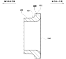
- Figure 21 shows an inner ring 100 that constitutes a radial angular ball bearing.
- the inner ring 100 has an inner ring raceway 101 with a cross-sectional shape that is approximately a quarter-circular arc at the axial middle of the outer peripheral surface.
- the inner ring 100 also has a large diameter portion (groove shoulder portion, flange portion) 102 with a cylindrical surface on the outer peripheral surface on one axial side (right side in Figure 21), and a small diameter portion 103 with a cylindrical surface on the outer peripheral surface on the other axial side (left side in Figure 21).
- Cylindrical machine parts such as the inner rings of angular contact ball bearings, are made by forging metal material and then performing finishing processes such as cutting and grinding.
- Patent document 1 JP Patent Publication 2005-288505A describes a method for producing two sets of inner and outer rings, each of which constitutes a tapered roller bearing, from one cylindrical metal material.
- the method described in Patent document 1 includes a step of hot forging a cylindrical metal material to obtain a stepped cylindrical pre-processed material, and a step of separating the pre-processed material into two cylindrical post-processed materials having different diameters.
- the method described in Patent document 1 further includes a step of cold forging and separating the smaller diameter of the two post-processed materials to obtain two cylindrical members having different diameters, and then finishing these cylindrical members to obtain a set of inner and outer rings, and a step of cold forging and separating the larger diameter of the two post-processed materials to obtain two cylindrical members having different diameters, and then finishing these cylindrical members to obtain another set of inner and outer rings.
- the manufacturing method described in Patent Document 1 when the axial dimensions of the inner and outer rings of each pair are approximately the same, the tubular members from which these inner and outer rings are obtained can be manufactured with good material yield.
- the manufacturing method described in Patent Document 1 is not suitable for mass production of inner rings that are used in combination with outer rings with significantly different axial dimensions, such as the inner rings of hubs that make up a hub unit bearing that supports the wheels of a vehicle relative to the suspension system.
- An aspect of the present invention aims to provide a manufacturing method that is advantageous in reducing manufacturing costs and/or improving product quality.
- a method for manufacturing a bearing element in one aspect of the present invention includes a first step of preparing an upset-machined workpiece, a second step of forming a recess, a flange, and a first axial surface in the workpiece by one or two plastic processes, and a third step of punching out the bottom of the recess in the workpiece.
- the recess has an axial depth relative to the first axial surface, and the flange extends radially outward.
- the first axial surface formed in the second step provides one end surface of the bearing element.
- the flange formed in the second step has a surface height at its radially outer end that is substantially the same as or greater than the first axial surface.
- the tubular member has an outer peripheral surface having a cylindrical large diameter portion provided on one axial side, a cylindrical small diameter portion provided on the other axial side, and a connecting surface portion connecting the large diameter portion and the small diameter portion.
- the method for manufacturing a tubular member includes a swaging process in which a cylindrical raw material is crushed in the axial direction to obtain a disk-shaped material having an axial dimension smaller than the axial dimension of the raw material and an outer diameter larger than the outer diameter of the raw material, a forming process in which the disk-shaped material is plastically processed to obtain an intermediate material including an intermediate tubular portion having the large diameter portion, the small diameter portion, and the connecting surface portion on the outer peripheral surface, and a partition portion that closes the end opening on the other axial side of the intermediate tubular portion, and a punching process in which the radially inner portion of the intermediate tubular portion and the partition portion are punched out in the axial direction.
- the axial dimension of the intermediate material or the axial dimension of a spare intermediate material obtained during the forming process is larger than the axial dimension of the tubular member.
- the mechanical device includes a cylindrical mechanical part having an outer circumferential surface with a cylindrical large diameter portion provided on one axial side, a cylindrical small diameter portion provided on the other axial side, and a connecting surface portion connecting the large diameter portion and the small diameter portion.
- the metal flow (fiber flow, grain flow) inside the mechanical part has an inclined portion in the axial middle portion of the mechanical part that is inclined radially outward as it moves from the other axial side to the one axial side, and the metal flow is denser in the inclined portion than in the portion surrounding the inclined portion.
- the method for manufacturing a bearing includes the steps of manufacturing a bearing element by the above-described manufacturing method, and assembling a bearing using the bearing element.
- a method for manufacturing a mechanical part includes a step of manufacturing a mechanical part by the above-described manufacturing method.
- a method for manufacturing a mechanical device includes a step of manufacturing a bearing element by the above-mentioned manufacturing method.
- a method for manufacturing a vehicle includes a step of manufacturing a bearing element by the above-described manufacturing method.
- the bearing comprises a bearing element having a trace of having been manufactured by the above-mentioned manufacturing method.
- the bearing according to one aspect of the present invention comprises a main body having a cylindrical body and a flange extending outward from the cylindrical body.
- the main body further has a first axial surface which is one end surface in the axial direction, a second axial surface which is another end surface in the axial direction, an inner peripheral surface of the cylindrical body, a first outer peripheral surface which is the outer peripheral surface of the cylindrical body, a second outer peripheral surface which is the outer peripheral surface of the flange, and a transition surface between the first outer peripheral surface and the second outer peripheral surface.
- the flange has a first angle between the first axial surface and the second outer peripheral surface, and a second angle between the transition surface and the second outer peripheral surface.
- the metal flow of the main body has a first pattern which is continuous along the first axial surface in the vicinity of the first axial surface, a second pattern which is continuous along the second outer peripheral surface in the vicinity of the second outer peripheral surface, a third pattern which is continuous along the transition surface in the vicinity of the transition surface, and a plurality of continuous lines which are each continuous across the first pattern, the second pattern, and the third pattern.
- the intervals between the continuous lines in the third pattern are narrower than the intervals between the continuous lines in the first pattern.
- the continuous lines have a plurality of corner elements arranged near the first corner. The corner elements have sharper corners closer to the first corner.
- a manufacturing method is provided that is advantageous in reducing manufacturing costs and/or improving product quality.
- FIG. 1 is a cross-sectional view of a hub unit bearing which is a mechanical device according to a first embodiment.
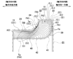
- FIG. 2 is a partial cross-sectional view of an inner ring that constitutes the hub unit bearing of the first embodiment.
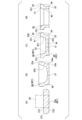
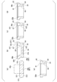
- 3A to 3C are cross-sectional views showing the manufacturing method of the cylindrical member of the first embodiment in the order of steps.
- FIG. 4A is a cross-sectional view showing a final stage of the second step in the manufacturing method of the cylindrical member of the first embodiment
- FIG. 4B is an enlarged view of part A in FIG. 4A.
- Part (a) of Figure 5 is a half cross-sectional view showing the start of the second step in the manufacturing method for the tubular member of the first embodiment, and part (b) is a half cross-sectional view showing the end of the second step.
- FIG. 6 is a cross-sectional view showing the final stage of the third step in the method for manufacturing the cylindrical member of the first embodiment.
- Part (a) of Figure 7 is a half cross-sectional view showing the start of the third step in the manufacturing method for a tubular member of the first embodiment, and part (b) is a half cross-sectional view showing the end of the third step.
- 8A to 8C are cross-sectional views showing the manufacturing method of the cylindrical member of the second embodiment in the order of steps.
- Part (a) of Figure 9 is a half cross-sectional view showing the start of the second step in the manufacturing method for a tubular member of the second embodiment, and part (b) is a half cross-sectional view showing the end of the second step.
- 10A to 10C are cross-sectional views showing the manufacturing method of the cylindrical member of the third embodiment in the order of steps.
- FIG. 11 is a cross-sectional view showing the final stage of the second step in the manufacturing method of the cylindrical member according to the third embodiment.
- 12A to 12C are cross-sectional views showing the manufacturing method of the cylindrical member of the fourth embodiment in the order of steps.
- Part (a) of Figure 13 is a half-sectional view showing the start of the third step in the manufacturing method for the tubular member of the first embodiment, and part (b) is a half-sectional view showing the end of the third step.
- 14A to 14C are cross-sectional views showing the manufacturing method of the cylindrical member of the fifth embodiment in the order of steps.
- FIG. 15 is a cross-sectional view showing the final stage of the second step in the manufacturing method for the cylindrical member according to the fifth embodiment.
- 16A to 16C are cross-sectional views showing the manufacturing method of the cylindrical member of the sixth embodiment in the order of steps.
- FIG. 17 is a partial enlarged view showing the final stage of the second step in the manufacturing method for the cylindrical member according to the sixth embodiment.
- FIG. 18A to 18C are cross-sectional views showing the manufacturing method of the cylindrical member of the seventh embodiment in the order of steps.
- FIG. 19 is a partial enlarged view showing the final stage of the third step in the manufacturing method for the cylindrical member according to the seventh embodiment.
- 20A to 20C are cross-sectional views showing the manufacturing method of the cylindrical member of the eighth embodiment in the order of steps.
- FIG. 21 is a cross-sectional view of an inner ring that constitutes a radial angular contact ball bearing.
- 22A to 22C are cross-sectional views showing a comparative example of a method for manufacturing a cylindrical member in the order of steps.
- FIG. 23 is an enlarged view of the upper right portion of part (b) of FIG.
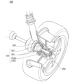
- FIG. 24 is a partial schematic diagram of a vehicle equipped with a hub unit bearing (bearing, bearing device).
- the manufacturing method for a bearing element comprises a first step (initial preparation step), a second step (plastic processing step), and a third step (punching step). Additionally, the manufacturing method for a bearing element (cylindrical member) can comprise at least one other step in addition to the above steps. According to this manufacturing method, the forming load is kept small, and the material usage efficiency (material yield) is improved. In addition, the strength and/or quality of the product is improved.
- a workpiece (WP1) is prepared.
- a workpiece (WP1) having a predetermined shape that has been upset is supplied, or a workpiece (WP1) having a predetermined shape is obtained by upset processing in the first step.
- the workpiece (WP1) prepared in the first step is used in the next step.
- the workpiece (WP1) prepared in the first step has a generally cylindrical shape (generally a disk shape) including a first end face (ES1), a second end face (ES2), and an outer peripheral surface (CS1).
- the first end face (ES1) is a relatively uniform flat or curved surface.
- the first end face (ES1) can have another shape.
- the second end face (ES2) is the surface opposite the first end face (ES1).
- the peripheral surface (CS1) of the workpiece (WP1) has a curved shape whose diameter changes along the axial direction.
- the outer diameter (radial width) is set larger than the axial length (thickness, height) between the first end face (ES1) and the second end face (ES2) of the workpiece (WP1).
- AL1/DM1 can be set to, for example, approximately 1/2, 1/3, 1/4, 1/5, 1/6, 1/7, 1/8, 1/9, or 1/10 or less.
- the above values are one example, and other values may be applicable in other examples.
- a workpiece (WP1) having a deformed shape of the above shape or a shape other than the above can be prepared.
- the upsetting process in the first step includes a pressurizing process (e.g., cold forging) that reduces the axial length (height) of the blank and increases its outer diameter (radial width).
- a pressurizing process e.g., cold forging
- the raw material (20, 20a) is compressed in the axial direction using a press device to form a workpiece (WP1) having a shape that is a deformation of an approximately cylindrical shape (approximately a disc shape) or a shape different from the approximately cylindrical shape.
- the workpiece (WP1) obtained in the first process can have a thickness change (volume change) provided in a predetermined area in the radial direction.
- the thickness change can include a groove having a predetermined depth and extending in the circumferential direction, and/or a protrusion having a predetermined height and extending in the circumferential direction.
- a processing tool is designed based on, for example, the shape parameters of the final bearing element/cylindrical member and the processing parameters in other processes, and the initial shape of the workpiece (WP1) is set.
- shape control in the initial stage improves the efficiency of material use (material yield).
- the strength of the product is improved based on the flow form of the material.
- the second process forms a recess (DP1), a flange (FR1), and a first axial surface (AX1) in the workpiece (WP1) by one or two plastic processes using a punching tool (e.g., hot forging).
- the first axial surface (AX1) is formed by plastic processing of the first end surface (ES1) of the workpiece (WP1).
- the workpieces (WP3, WP4) formed in the second process have a peripheral wall (CW1) surrounding the recess (DP1), and a flange (FR1) having a shape extending radially outward from the peripheral wall (CW1).
- the flange (FR1) is provided on the side of the peripheral wall (CW1) facing the first axial surface (AX1).
- the peripheral wall (CW1) has a second axial surface (AX2) which is an axial end surface arranged on the opposite side to the first axial surface (AX1).
- the first axial surface (AX1) and/or the second axial surface (AX2) includes a surface perpendicular to the axial direction.
- the first axial surface (AX1) formed in the second step provides one end surface of the bearing element (the cylindrical member (21, 21a)).
- at least a portion of the first axial surface (AX1) is formed in the flange (FR1).
- the recess (DP1) has an axial depth relative to the first axial surface (AX1).
- the flange (FR1) formed in the second step has a surface height at the radial outer end (ROE), which is a region near the radial outer end/outer edge, that is substantially the same as or greater than the first axial surface (AX1).
- the axial surface profile of the radial outer end (ROE) has a height position in the axial direction that is equal to or greater than the first axial surface (AX1) with respect to a predetermined reference plane that intersects the flange (FR1) and is perpendicular to the axial direction.
- the radial range of the radial outer end (ROE) is the radial length from the radial outer end/outer edge of the flange (FR1), and can be, for example, 10, 5.0, 4.0, 3.0, 2.0, 1.0, 0.8, 0.6, 0.4, or 0.2 mm or less.
- EW1/FD1 can be set to approximately 1/10, 1/12, 1/14, 1/16, 1/18, 1/20, 1/30, 1/40, or 1/50 or less.
- the above values are one example, and other values can be applied in other examples.
- a deformed shape of the above shape or a shape other than the above can be set.
- the second step includes simultaneously forming a recess (DP1), a flange (FR1), a first axial surface (AX1), and an annular protrusion (AP1) in the upset-machined workpiece (WP1) using a first punch (PC1).
- the recess (DP1), the flange (FR1), the first axial surface (AX1), and the annular protrusion (AP1) are formed by a single punching process.
- the annular protrusion (AP1) has a shape that protrudes axially outward from the first axial surface (AX1) at the radial outer end (ROE) of the flange (FR1).
- the first punch (PC1) has a first base (P11), a first protrusion (P12), and a first punch surface (P13) including a tip region of the first protrusion (P12).
- the first punch surface (P13) corresponds to the bottom surface of the depression (DP1).
- the first punch (PC1) has a second punch surface (P14) including the outer peripheral surface of the first protrusion (P12), and a third punch surface (P15) including an annular surface provided on the first base (P11).
- the second punch surface (P14) corresponds to the inner wall surface (inner peripheral surface) of the depression (DP1).
- the third punch surface (P15) corresponds to the first axial surface (AX1).
- the first punch (PC1) has a fourth punch surface (P16) which is a transition surface between the second punch surface (P14) and the third punch surface (P15), and a step (depression, groove) (P17) which is provided near the radial outer edge of the first punch surface (P13) and extends in the circumferential direction.
- the step (P17) corresponds to the annular protrusion (AP1).
- the first punch (PC1) is designed based on the shape parameters of the final bearing element (cylindrical member) and the processing parameters in other processes, and the shape of the workpiece (WP4) after plastic processing is set. Such shape control improves the efficiency of material use (material yield). In addition, the strength of the product is improved based on the flow form of the material.
- the second step includes a first plastic processing step in which a preliminary depression (DP0) is formed in the upset workpiece (WP1) using a second punch (PC2).
- the second step also includes a second plastic processing step in which a depression (DP1), a flange (FR1), and a first axial surface (AX1) are simultaneously formed in the workpiece (WP2) in which the preliminary depression (DP0) has been formed after the first plastic processing step using a third punch (PC3).
- the simultaneous formation of the depression (DP1), the flange (FR1), and the first axial surface (AX1) includes filling the corner of the flange (FR1) at the radial outer end (ROE).
- the corner (edge shape) of the flange (FR1) has an approximately right-angled shape.
- the curved edge of the workpiece (WP2) after the first plastic processing changes to a nearly right-angled edge of the workpiece (WP3) after the second plastic processing.
- the second plastic processing by the third punch (PC3) causes part of the material of the workpiece (WP2) to flow radially outward, providing a workpiece (WP3) with an increased thickness near the radially outer end.
- the second punch (PC2) has a second base (P21) and a second protrusion (P22), and the third punch (PC3) has a third base (P31) and a third protrusion (P32).
- a preliminary depression (DP0) is formed in the workpiece by the second protrusion (P22) of the second punch (PC2).
- a depression (DP1) is formed in the workpiece by the third protrusion (P32) of the third punch (PC3).
- the second punch (PC2) has a fifth punch surface (P25) including a tip region of the second protrusion (P22).
- the fifth punch surface (P25) corresponds to the bottom surface of the preliminary depression (DP0).
- the second punch (PC2) has a sixth punch surface (P26) including an outer peripheral surface of the second protrusion (P22).
- the sixth punch surface (P26) corresponds to the inner wall surface of the preliminary depression (DP0).
- the third punch (PC3) has a seventh punch surface (P37) including the tip region of the third protrusion (P32).
- the seventh punch surface (P37) corresponds to the bottom surface of the depression (DP1).
- the third punch (PC3) has an eighth punch surface (P38) including the outer peripheral surface of the third protrusion (P32) and a ninth punch surface (P39) including an annular surface provided on the third base (P31).
- the eighth punch surface (P38) corresponds to the inner wall surface (inner peripheral surface) of the depression (DP1).
- the ninth punch surface (P39) corresponds to the first axial surface (AX1).
- the third punch (PC3) has a tenth punch surface (P40) which is a transition surface between the eighth punch surface (P38) and the
- the axial length of the third protrusion (P32) of the third punch (PC3) is smaller than that of the second protrusion (P22) of the second punch (PC2).
- the inclination ( ⁇ 11) of the outer peripheral surface (sixth punch surface) (P26) of the second protrusion (P22) of the second punch (PC2) relative to the central axis is larger than the inclination ( ⁇ 12) of the outer peripheral surface (P35) of the third protrusion (P32) of the third punch (PC3) relative to the central axis.
- the axial length of the third protrusion (P32) of the third punch (PC3) is smaller than that of the second protrusion (P22) of the second punch (PC2).
- the outer diameter of the second base (P21) is substantially the same as that of the third base (P31).
- the average outer diameter of the second protrusion (P22) is larger than that of the third protrusion (P32).
- the fifth punch surface (P25) of the second punch (PC2) has a surface shape in which the surface height in the center is greater than in other regions.
- the seventh punch surface (P37) of the third punch (PC3) has a surface shape that is more uniform overall than the fifth punch surface (P25).
- the second punch (PC2) and third punch (PC3) are designed based on the shape parameters of the final bearing element (cylindrical member) and the processing parameters of other processes, and the shape of the workpiece (WP3) after plastic processing is set. This shape control improves the efficiency of material usage (material yield). In addition, the strength of the product is improved based on the flow form of the material.
- the tubular member (21, 21a) has an outer peripheral surface having a cylindrical large diameter portion (22) provided on one axial side, a cylindrical small diameter portion (23) provided on the other axial side, and a connecting surface portion (24) connecting the large diameter portion and the small diameter portion.
- the manufacturing method of the tubular member (21, 21a) includes a swaging process in which a cylindrical raw material (20, 20a) is crushed in the axial direction to obtain a disk-shaped material (25, 25a, 25b) having an axial dimension smaller than the axial dimension of the raw material (20, 20a) and an outer diameter larger than the outer diameter of the raw material (20, 20a), and a plastic processing process in which the disk-shaped material (25, 25a, 25b) is subjected to plastic processing to form the large diameter portion (22) and the small diameter portion (24) on the outer peripheral surface.
- the method includes a molding step of obtaining an intermediate material (32, 32a, 32b, 32c) including an intermediate tubular portion (30, 30a) having a small diameter portion (23) and the connection surface portion (24), and a partition portion (31, 31a, 31b) that closes the end opening on the other axial side of the intermediate tubular portion (30, 30a), and a punching step of punching out the radially inner portion of the intermediate tubular portion (30, 30a) and the partition portion (31, 31a, 31b) in the axial direction.
- the axial dimension of the intermediate material (32, 32a, 32b, 32c) or the axial dimension of the preliminary intermediate material (28, 28a, 28b) obtained during the molding step is larger than the axial dimension of the tubular member (21, 21a).
- the cylindrical member (21, 21a) can have an inner circumferential surface having an inclined surface portion (41) provided at one axial end, the inner diameter of which increases toward one axial end, and a cylindrical surface portion (42) provided at an axial intermediate portion and at the end on the other axial end.
- the intermediate cylindrical portion (30, 30a) can also have the inclined surface portion (41) at one axial end of the inner circumferential surface.
- the forming process may include a pre-forming process in which the disk-shaped material (25, 25a, 25b) is subjected to plastic processing to obtain the preliminary intermediate material (28, 28a, 28b) having a preliminary intermediate tubular portion (26, 26a, 26b) and a partition portion (31, 31a, 31b) that closes the end opening on the other axial side of the preliminary intermediate tubular portion (26, 26a, 26b), and a post-forming process in which the preliminary intermediate material (28, 28a, 28b) is crushed in the axial direction inside the inner surface of a die having a shape that conforms to the outer circumferential surface of the intermediate material (32, 32a, 32b, 32c) to obtain the intermediate material (32, 32a, 32b, 32c).
- the axial dimension of the preliminary intermediate material (28, 28a, 28b) is greater than the axial dimension of the tubular member (21, 21a), and the axial dimension of the intermediate material (32, 32a, 32b, 32c) is equal to the axial dimension of the tubular member (21, 21a).
- At least the radially outer portion of the end face on one axial side of the preliminary intermediate cylindrical portion (26, 26a, 26b) can be prevented from contacting the forming die used for performing plastic processing.
- the outer diameter of one axial side portion of the spare intermediate cylindrical portion (26, 26a, 26b) is slightly smaller than the outer diameter of the large diameter portion (22), and the outer diameter of the other axial side portion of the spare intermediate cylindrical portion (26, 26a, 26b) is slightly smaller than the outer diameter of the small diameter portion (23).
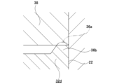
- the intermediate cylindrical portion (30, 30a) has an annular protrusion (36, 36a, 36b) protruding in one axial direction at the radially outer end of the end on one axial side.
- the forming process is a process of obtaining the intermediate material (32, 32a, 32b, 32c) by performing plastic processing on the disk-shaped material (25, 25a, 25b), and the axial dimension of the intermediate material (32, 32a, 32b, 32c) is larger than the axial dimension of the cylindrical member (21, 21a) by the axial height of the annular protrusion (36, 36a, 36b), and includes a removal process of removing the annular protrusion (36, 36a, 36b) after the forming process.
- a homogenizing process can be performed prior to the removing process, in which the annular convex portion (36, 36a, 36b) formed in the molding process is crushed in the axial direction to make the axial height of the annular convex portion (36, 36a, 36b) uniform over the entire circumference.
- the mechanical device includes a cylindrical mechanical part (10) having an outer circumferential surface with a cylindrical large diameter portion (18) provided on one axial side, a cylindrical small diameter portion (19) provided on the other axial side, and a connecting surface portion (7a) connecting the large diameter portion (18) and the small diameter portion (19).
- the manufacturing method for the mechanical device includes a step of manufacturing the mechanical part (10) by performing a finishing process on the cylindrical member (21, 21a) manufactured by the above-mentioned manufacturing method for the cylindrical member.
- the mechanical component is an inner ring (10)
- the connection surface of the mechanical component is configured by an inner ring raceway (7a) having an arc-shaped cross-sectional shape
- the mechanical device is a bearing device (1).
- the bearing device is a hub unit bearing (1) for supporting an automobile wheel so that it can rotate freely relative to a suspension system.
- the vehicle includes a mechanical device (1).
- the method for manufacturing the vehicle includes a step of manufacturing the mechanical device (1) by the above-described method for manufacturing the mechanical device.
- the machine device (1) includes a cylindrical machine part (10) having an outer circumferential surface with a cylindrical large diameter part (18) provided on one axial side, a cylindrical small diameter part (19) provided on the other axial side, and a connecting surface part (7a) connecting the large diameter part and the small diameter part.
- the metal flow (fiber flow, grain flow line) inside the machine part has an inclined part (Tp) in the axial middle part of the machine part that is inclined radially outward as it moves from the other axial side to the one axial side, and the metal flow is denser in the inclined part (Tp) than the part around the inclined part (Tp).
- the mechanical component is an inner ring (10)
- the connection surface of the mechanical component is configured by an inner ring raceway (7a) having an arc-shaped cross-sectional shape
- the mechanical device is a bearing device (1).
- the bearing device is a hub unit bearing (1) for supporting an automobile wheel so that it can rotate freely relative to a suspension system.
- the vehicle includes the above-described mechanical device.
- the above-mentioned manufacturing method for a tubular member makes it possible to reduce the manufacturing costs of mechanical parts made from a tubular member having an outer circumferential surface with a large diameter portion with a cylindrical surface provided on one axial side, a small diameter portion with a cylindrical surface provided on the other axial side, and a connecting surface portion that connects the large diameter portion and the small diameter portion.
- the bearing element includes a body (10) having a cylindrical body (TBB) and a flange (FRG) extending outward from the cylindrical body (TBB).
- the body (10) has a first axial surface (AS1) which is one end surface in the axial direction, and a second axial surface (AS2) which is another end surface in the axial direction.
- the body (10) also has an inner peripheral surface (IS1) of the cylindrical body (TBB), a first outer peripheral surface (CS1) which is the outer peripheral surface of the cylindrical body (TBB), a second outer peripheral surface (CS2) which is the outer peripheral surface of the flange (FRG), and a transition surface (CS3) between the first outer peripheral surface (CS1) and the second outer peripheral surface (CS2).
- the flange (FRG) has a first angle (FE1) between the first axial surface (AS1) and the second outer peripheral surface (CS2), and a second angle (FE2) between the transition surface (CS3) and the second outer peripheral surface (CS2).
- the bearing element has traces of production by the above-mentioned production method.
- the traces are metal flows (metal fiber flows, fibrous metal structure, grain flows) observed in a cross section of the bearing element (cylindrical member).
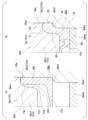
- Figures 2, 5, 7, 9, and 15 show an example of metal flows in an axial cross section (axial cross section) of a bearing element (cylindrical member) and its production process.
- the traces can also be confirmed based on a texture analysis and/or a structure analysis that is different from an analysis based on metal flows.
- the metal flow of the main body (10) has a first pattern (PA1), a second pattern (PA2), and a third pattern (PA3).
- the first pattern (PA1) is continuous along the first axial surface (AS1) in the vicinity of the first axial surface (AS1).
- the second pattern (PA2) is continuous along the second outer peripheral surface (CS2) in the vicinity of the second outer peripheral surface (CS2).
- the third pattern (PA3) is continuous along the transition surface (CS3) in the vicinity of the transition surface (CS3).
- the metal flow of the main body (10) further has a plurality of continuous lines (CL1, CL2, CL3) each of which is continuous across the first pattern (PA1), the second pattern (PA2), and the third pattern (PA3).
- the spacing between the multiple continuous lines (CL1, CL2, CL3) in the third pattern (PA3) is narrower than the spacing between the multiple continuous lines (CL1, CL2, CL3) in the first pattern (PA1).
- the multiple continuous lines (CL1, CL2, CL3) have multiple corner elements (CE1, CE2, CE3) arranged near the first corner (FE1).
- the multiple corner elements (CE1, CE2, CE3) have sharper corners as they are closer to the first corner (FE1).
- the corner element (CE1) is closest to the first corner (FE1).
- the corner element (CE3) is farther from the first corner (FE1) than the corner element (CE1) and the corner element (CE2).
- the corner element (CE1) has a sharper corner than the corner element (CE2).
- Corner element (CE2) has a sharper corner than corner element (CE3).
- At least one of the multiple corner elements has a protruding shape that protrudes toward the first corner (FE1).
- At least one of the multiple corner elements (CE1, CE2, CE3) has a first curvature (CV1) that is convex toward the first corner (FE1) and a second curvature (CV2) that is convex toward the inside of the first corner (FE1).
- the first curvature (CV1) and the second curvature (CV2) are arranged continuously.
- the metal flow of the main body (10) has a fourth pattern (PA4) including a plurality of line elements extending obliquely with respect to the central axis of the main body (10) from the inner circumferential surface (IS1) toward the transition surface (CS3).
- the spacing between the plurality of line elements in the radially outer region is narrower than the spacing between the plurality of line elements in the radially inner region.
- the plurality of line elements in the radially outer region have a partial curvature (CV3) that is convex radially inward.
- Bearing elements with a predetermined metal flow are advantageous for reducing manufacturing costs and/or increasing strength.
- Continuous line elements with metal flow are advantageous for increasing the strength of the main body.
- the bearing comprises the above-mentioned bearing elements, which is advantageous in reducing the cost of the bearing.
- the machine is equipped with the above-mentioned bearing, which is advantageous for reducing the cost of the machine.
- a vehicle is equipped with the above-mentioned bearing, which is advantageous for reducing the cost of the vehicle.
- FIG 24 is a partial schematic diagram of a vehicle 200 equipped with a hub unit bearing (bearing, bearing device) 151.
- the above-mentioned bearing can be applied to both hub unit bearings for driving wheels and hub unit bearings for driven wheels.
- the hub unit bearing 151 is for a driving wheel and includes an outer ring 152, a hub 153, and multiple rolling elements 156.
- the outer ring 152 is fixed to a knuckle 201 of the suspension device using bolts or the like.
- the wheel (and braking rolling element) 202 is fixed to a flange (rotating flange) 153A provided on the hub 153 using bolts or the like.
- the vehicle 200 can also have a support structure similar to that described above for the hub unit bearing 151 for the driven wheels.
- a cylindrical raw material which is a single metal material, is crushed in the axial direction to obtain a disk-shaped material (workpiece) 105, as shown in FIG. 22(a), which has a smaller axial dimension and a larger outer diameter than the raw material.
- the disk-shaped material 105 is subjected to plastic processing such as forward and backward extrusion processing to obtain a cup-shaped intermediate material 106 as shown in Figure 22 (b).
- the intermediate material 106 comprises an intermediate tubular portion 107 having the same outer peripheral surface shape as that of the tubular member 104 and the same axial dimension as that of the tubular member 104, and a partition portion 108 that closes the end opening on the other axial side of the end portion on one axial side (upper side in Figure 22 (b)) and the other axial side (lower side in Figure 22 (b)) of the intermediate tubular portion 107.
- the radially inner portion of the intermediate tubular portion 107 and the partition wall portion 108 of the intermediate material 106 are punched out in the axial direction to obtain the tubular member 104.
- the tubular member 104 is produced by hot forging, an oxide film (black skin) is formed on its surface. If this oxide film remains on the surface of the inner ring 100 after completion, it becomes difficult to ensure the shape precision and surface roughness precision required of the inner ring 100. For this reason, it is necessary to ensure that the tubular member 104 has a machining allowance large enough to remove the oxide film on the surface during finishing.
- the intermediate material 106 is obtained by performing forward and backward extrusion processing on the disk-shaped material 105, there are cases where the material (metal material) flowing toward one axial side in the molding space of the intermediate material 106 present inside the molding die does not sufficiently reach the radially outer end of the end on one axial side, which is the final point.
- the radially outer end of the end face on one axial side of the intermediate material 106 and the tubular member 104 will have a recessed shape, for example, as shown by the dashed line ⁇ in FIG. 23 (in the illustrated example, the shape is recessed toward the other axial side as it moves radially outward).
- Another method for eliminating the above-mentioned inconveniences is to increase the volume of the raw material and increase the overall thickness of the machining allowance provided on the tubular member 104.
- This method even if the radially outer end of the end face on one axial side of the tubular member 104 has an undercut shape as shown by the dashed line ⁇ in Figure 23, it is easy to ensure that the radially outer end of the end face on one axial side of the tubular member 104 has enough machining allowance to remove the oxide film by finishing.
- this method requires a large amount of material to be removed during the finishing process, which means that the yield rate when manufacturing the inner ring 100 is reduced, and the manufacturing costs of the inner ring 100 increase.
- This example is an example of manufacturing a cylindrical member (bearing element) to obtain the inner ring 10 of the hub unit bearing 1 shown in Figure 1.
- the manufacturing method for a tubular member can be used to manufacture any tubular member having a cylindrical large diameter portion provided on one axial side, a cylindrical small diameter portion provided on the other axial side, and an outer circumferential surface having a connecting surface portion connecting the large diameter portion and the small diameter portion.
- the manufacturing method for a tubular member can be used to manufacture a bearing device having a structure different from the example shown in FIG. 1, specifically, a tubular member (bearing element) for obtaining an inner ring or sliding bearing that constitutes a single-row or double-row angular ball bearing.
- the inner ring or sliding bearing can be manufactured by performing finishing processes such as cutting and grinding on the tubular member (bearing element).
- the manufacturing method for a tubular member can also be used to manufacture tubular members for obtaining various mechanical parts that make up mechanical devices such as machine tools or vehicles.
- the mechanical parts can be manufactured by subjecting the tubular member to finishing processes such as cutting and grinding.
- the material of the tubular member is not particularly limited as long as it is a metal material that can be hot forged, and various metal materials such as iron alloys such as bearing steel, aluminum alloys, copper alloys, etc. can be used.
- the axially inner side is the right side in FIG. 1, which is the center side in the width direction of the vehicle when assembled to the vehicle
- the axially outer side is the left side in FIG. 1, which is the outer side in the width direction of the vehicle when assembled to the vehicle.
- the hub unit bearing 1 in this example comprises an outer ring 2, a hub 3, and multiple rolling elements 4a, 4b.
- the outer ring 2 is made of a hard metal such as medium carbon steel, and has double-row outer ring raceways 5a, 5b on its inner circumferential surface.
- each of the outer ring raceways 5a, 5b is angular and has a cross-sectional shape that is approximately a quarter-circular arc.
- the outer ring 2 has a stationary flange 6 at the axially middle portion that protrudes radially outward.
- the stationary flange 6 is a portion that is used to support and fix the outer ring 2 to the knuckle of the suspension device.
- the hub 3 has double-row inner ring raceways 7a, 7b on its outer circumferential surface.
- each of the inner ring raceways 7a, 7b is angular and has a cross-sectional shape that is approximately a quarter-circular arc.
- the hub 3 has a rotating flange 8 that protrudes radially outward at a portion located axially outward from the outer ring 2.
- the rotating flange 8 is a part that connects and fixes the wheel and the braking rotor that constitute the wheel.
- the outer peripheral surface of the inner ring 10 is configured by connecting a cylindrical large diameter portion 18 provided on the axially inner portion, which is one axial side portion, and a cylindrical small diameter portion 19 provided on the axially outer portion, which is the other axial side portion, by the inner ring raceway 7a on the axially inner side, which is the connecting surface portion.
- the inner peripheral surface of the inner ring 10 has an inclined surface portion 39 provided at the axially inner end portion, which is on one axial side, and the inner diameter of which increases toward the axially inner side, and a cylindrical surface portion 40 provided at the axially intermediate portion and the axially outer end portion, which is on the other axial side.
- the inclined surface portion 39 has a cross-sectional shape that is approximately a quarter-circular arc.
- the inclined surface portion can also be configured with a conical surface having a linear generatrix shape.
- both axial end faces of the inner ring 10 are made up of flat surfaces perpendicular to the axial direction.
- the rolling elements 4a, 4b are made of iron alloys such as bearing steel or ceramics, and multiple elements are arranged between the double-row outer ring raceways 5a, 5b and the double-row inner ring raceways 7a, 7b.
- the rolling elements 4a, 4b are made of balls, and a back-to-back contact angle and preload are applied to the rolling elements 4a, 4b in each row.
- the pitch circle diameter of the rolling elements 4a in the axially outer row is the same as the pitch circle diameter of the rolling elements 4b in the axially inner row.
- the hub unit bearing can also be applied to a PCD type hub unit bearing with different pitch circle diameters, in which the pitch circle diameters of the rolling elements in the axially inner row are different from the pitch circle diameters of the rolling elements in the axially outer row.
- the openings on both axial sides of the rolling element installation space 14 that exist between the inner circumferential surface of the outer ring 2 and the outer circumferential surface of the hub 3 are blocked by sealing devices 15a, 15b, respectively. This prevents foreign matter such as muddy water from entering the rolling element installation space 14 from the outside through the openings on both axial sides of the rolling element installation space 14, and prevents the lubricating grease sealed in the rolling element installation space 14 from leaking to the outside.
- the axially inner seal device 15a comprises a seal ring 16 fitted into the inner peripheral surface of the axially inner end of the outer ring 2, and a slinger 17 fitted onto the large diameter portion 18 of the inner ring 10, and is configured as a combined seal ring in which the tips of the multiple seal lips that make up the seal ring 16 are in sliding contact with the surface of the slinger 17.
- the large diameter portion 18 of the inner ring 10 is used as a fitting portion for fitting the slinger 17 onto the outside.
- the axial direction refers to the axial direction of the workpiece, with one axial side being the upper side in Figs. 3 to 7 and the other axial side being the lower side in Figs. 3 to 7.
- the axial direction of each member shown in Figs. 3 to 7 coincides with the up-down direction.
- the up-down direction in Figs. 3 to 7 does not necessarily coincide with the up-down direction (vertical direction) during processing.
- the up-down direction in Figs. 3 to 7 can coincide with the horizontal direction, or can coincide with a direction inclined relative to both the up-down direction (vertical direction) and the horizontal direction.
- the plastic processing in this step is hot forging. Therefore, an oxide film (black skin) is formed on the surface of the tubular member 21 after this step. If such an oxide film remains on the surface of the completed inner ring 10, it will be difficult to ensure the shape precision and surface roughness precision required of the inner ring 10. For this reason, as shown by the two-dot chain line in Figure 2, it is necessary to ensure in the tubular member 21 a machining allowance that will be removed in the finishing step. Therefore, the tubular member 21 has a cylindrical shape with an overall contour that is larger than that of the inner ring 10 by the amount of the machining allowance.
- the outer peripheral surface of the tubular member 21 has a large diameter portion 22 in the form of a cylindrical surface provided on one axial side, a small diameter portion 23 in the form of a cylindrical surface provided on the other axial side, and a connecting surface portion (transition portion) 24 connecting the large diameter portion 22 and the small diameter portion 23.
- the large diameter portion 22 has an outer diameter larger than the large diameter portion 18 of the inner ring 10 by the amount of the machining allowance.
- the small diameter portion 23 has an outer diameter larger than the small diameter portion 19 of the inner ring 10 by the amount of the machining allowance.
- the connecting surface portion 24 has a cross-sectional shape that is approximately a quarter circle arc, and an outer diameter larger than the inner ring raceway 7a of the inner ring 10 by the amount of the machining allowance.
- the inner peripheral surface of the tubular member 21 has an inclined surface portion (curved surface portion) 41 provided at one axial end, whose inner diameter increases toward the inside of the axial direction, and a cylindrical surface portion 42 provided at the axial middle portion and the other axial end.
- the inclined surface portion 41 has an arc-shaped cross-sectional shape like the inclined surface portion 39 of the inner ring 10, and has an inner diameter smaller than that of the inclined surface portion 39 by the amount of the machining allowance.
- the cylindrical surface portion 42 has an inner diameter smaller than that of the cylindrical surface portion 40 of the inner ring 10 by the amount of the machining allowance.
- the end faces on both axial sides of the tubular member 21 are formed of flat surfaces perpendicular to the axial direction.
- the end face on one axial side of the tubular member 21 is located on one axial side of the end face on one axial side of the inner ring 10 by the amount of the machining allowance, and the end face on the other axial side of the tubular member 21 is located on the other axial side of the end face on the other axial side of the inner ring 10 by the amount of the machining allowance.
- the thickness of the removal allowance is not particularly limited, but must be at least thick enough to remove the oxide film, i.e., greater than or equal to the thickness of the oxide film. Assuming that the oxide film is 0.2 mm to 0.3 mm thick, the thickness of the removal allowance can be, for example, 0.3 mm to 1.0 mm, and preferably 0.3 mm to 0.5 mm. The above values are merely examples and are not limiting.
- This process includes a swaging process, a molding process, and a punching process.
- the cylindrical raw material 20 is crushed in the axial direction to obtain a disk-shaped material 25 having an axial dimension smaller than that of the raw material 20 and an outer diameter larger than that of the raw material 20, as shown in FIG. 3(a).
- the raw material 20 is obtained by cutting a long metal bar to a specified length.
- the outer peripheral surface of the disc-shaped material 25 has a substantially arc-shaped cross-sectional shape (generatrix shape) in which the outer diameter of the axial center portion is larger than the outer diameter of both axial ends.
- the outer diameter of the disc-shaped material 25, more specifically, the outer diameter of the axial center portion which is the maximum diameter portion of the disc-shaped material 25, is the same as or approximately the same as the outer diameter of the small diameter portion 23 of the tubular member 21.
- the outer diameter of the axial end portions which are the minimum diameter portions of the disc-shaped material 25 is slightly smaller than the outer diameter of the small diameter portion 23 of the tubular member 21.
- the disk-shaped material 25 is subjected to plastic processing to obtain an intermediate material 32 including an intermediate tubular portion 30 having a large diameter portion 22, a small diameter portion 23, and a connecting surface portion 24 on its outer circumferential surface, and a partition portion 31 that closes the end opening on the other axial side of the intermediate tubular portion 30.
- the molding process includes a pre-molding process and a post-molding process.
- the disk-shaped material 25 is subjected to a backward extrusion process, which is a plastic process, to obtain a cup-shaped preliminary intermediate material 28, as shown in FIG. 3(b), which includes a preliminary intermediate tubular portion 26 having an axial dimension larger than the axial dimension of the tubular member 21, and a partition portion 27 that closes the end opening on the other axial side of the preliminary intermediate tubular portion 26.
- a backward extrusion process which is a plastic process
- the shapes of the spare intermediate tubular portion and the partition wall are not particularly limited.
- the outer peripheral surface of the spare intermediate tubular portion 26 includes a cylindrical large diameter portion 22a provided on one axial side, a cylindrical small diameter portion 23a provided on the other axial side, and a connection surface portion (transition portion) 24a that connects the large diameter portion 22a and the small diameter portion 23a and has a cross-sectional shape of an approximately quarter-circular arc.
- the large diameter portion 22a has an outer diameter slightly smaller than the outer diameter of the large diameter portion 22 of the tubular member 21 by the insertion clearance into the large diameter portion 35a1 of the die 35a, and has an axial dimension larger than the axial dimension of the large diameter portion 22 of the tubular member 21.
- the small diameter portion 23a has an outer diameter slightly smaller than the outer diameter of the small diameter portion 23 of the tubular member 21 by the insertion clearance into the small diameter portion 35a2 of the die 35a, and has an axial dimension smaller than the axial dimension of the small diameter portion 23 of the tubular member 21.
- the connection surface portion 24a has a radius of curvature larger than the radius of curvature of the connection surface portion 24 of the tubular member 21.
- the inner peripheral surface of the spare intermediate cylindrical portion 26 is configured as a substantially conical cylindrical surface whose inner diameter increases from the other axial side toward the one axial side.
- the end face on one axial side of the spare intermediate cylindrical section 26 has a cross-sectional shape that is roughly an arc shape with one axial side being convex. That is, the radially inner portion of the end face on one axial side of the spare intermediate cylindrical section 26 is configured with a convex curved surface that is inclined toward the other axial side as it moves radially inward, and the radially outer portion of the end face on one axial side of the spare intermediate cylindrical section 26 is configured with a convex curved surface that is inclined toward the other axial side as it moves radially outward.
- the opening width (inner diameter) of one axial end of the spare intermediate tubular portion 26 is larger than the opening width (inner diameter) of one axial end of the tubular member 21.
- one axial side of the partition wall 27 is configured as a roughly conical surface that slopes radially inward toward the other axial side.
- the other axial end face of the spare intermediate material 28, which is formed by the other axial end face of the spare intermediate tubular portion 26 and the other axial side face of the partition wall portion 27, is formed by a single flat surface perpendicular to the axial direction.
- a recess that is recessed in the axial direction can be provided in the radial center of the end face on the other axial side of the preliminary intermediate material. Providing such a recess can facilitate the task of removing the end face on the other axial side of the preliminary intermediate material from the molding die after molding of the preliminary intermediate material.
- the material that constitutes the partition wall portion 27 is ultimately punched out and does not remain in the tubular member 21.
- the axial thickness of the partition wall portion 27 is made as small as possible, specifically, smaller than the radial thickness of the spare intermediate tubular portion 26. This improves the yield.
- the preforming process is carried out using a press processing device 29 as shown in Figures 4 and 5.
- the press processing device 29 is equipped with a die 29a, a die pin 29b, and a punch 29c, each of which is a forming die.
- the die 29a has an inner peripheral surface that has a shape that follows the outer peripheral surface of the spare intermediate material 28 to be obtained, i.e., the outer peripheral surface of the spare intermediate tubular portion 26.
- the inner peripheral surface of the die 29a has a stepped cylindrical shape that connects a large diameter portion 29a1 provided on one axial side and a small diameter portion 29a2 provided on the other axial side by a curved surface portion 29a3.
- the large diameter portion 29a1 has a shape that follows the large diameter portion 22a of the spare intermediate tubular portion 26,
- the small diameter portion 29a2 has a shape that follows the small diameter portion 23a of the spare intermediate tubular portion 26, and the curved surface portion 29a3 has a shape that follows the connecting surface portion 24a of the spare intermediate tubular portion 26.
- the die pin 29b is arranged on the inner diameter side of the small diameter portion 29a2 of the die 29a without any radial wobble.
- the tip end face of the die pin 29b on one axial side has a shape that conforms to the end face of the spare intermediate material 28 on the other axial side.
- the punch 29c is supported so as to be movable in the axial direction relative to the support table (not shown) of the press processing device 29.
- Punch 29c has a convex portion (projection) 29c1 in the center of the tip surface (end surface on the other axial direction).
- the outer peripheral surface of convex portion 29c1 has a shape that follows the radially inner portion of the end surface on one axial side of spare intermediate tube portion 26 and the portion of the inner peripheral surface of spare intermediate tube portion 26 that is located on one axial side of partition portion 27.
- the end surface on the other axial side, which is the tip surface of convex portion 29c1 has a shape that follows the side surface on one axial side of partition portion 27.
- punch 29c has an annular surface portion 29c2 that is bent radially outward from one axial end of the outer peripheral surface of protrusion 29c1.
- annular surface portion 29c2 is formed of a flat surface that is perpendicular to the central axis of punch 29.
- the press processing device 29 When the press processing device 29 performs rearward extrusion processing on the disk-shaped material 25 to obtain the preliminary intermediate material 28, the disk-shaped material 25 is first placed on one axial end face of the die pin 29b, as shown in FIG. 5(a).
- the radially outer portion of the end face on one axial side of the preliminary intermediate tubular portion 26 is not brought into contact with the annular surface portion 29c2 of the punch 29c. Therefore, in this example, the processing load in the pre-forming step can be reduced compared to when the entire end face on one axial side of the preliminary intermediate tubular portion 26 is brought into contact with the molding die for performing the rearward extrusion process. As a result, the durability of the die 29a, die pin 29b, and punch 29c can be ensured, and the manufacturing cost of the inner ring 10 can be reduced.
- the entire end face on one axial side of the preliminary intermediate cylindrical portion can be in contact with the molding die or not in contact with the molding die.
- the preliminary intermediate material 28 is crushed in the axial direction inside the inner peripheral surface of a die 35a having a shape that conforms to the outer peripheral surface of the intermediate material 32, to obtain a cup-shaped intermediate material 32 having an axial dimension equal to the axial dimension of the cylindrical member 21, as shown in FIG. 3(c).
- the intermediate material 32 comprises an intermediate tubular portion 30 and a partition wall portion 31 that closes the end opening on the other axial side of the intermediate tubular portion 30.
- the intermediate tubular portion 30 has an axial dimension equal to the axial dimension of the tubular member 21.
- the intermediate tubular portion 30 has an outer peripheral surface shape equal to the outer peripheral surface shape of the tubular member 21. That is, the outer peripheral surface of the intermediate tubular portion 30 has, in order from one axial side, a large diameter portion 22, a connection surface portion 24, and a small diameter portion 23.
- the end faces on both sides of the axial direction of the intermediate tubular portion 30 have the same shape as the end faces on both sides of the axial direction of the tubular member 21, i.e., a flat surface shape perpendicular to the axial direction.
- the end of the inner peripheral surface of the intermediate tubular portion 30 on one axial side has the same shape as the end of the inner peripheral surface of the tubular member 21 on one axial side. That is, the inner peripheral surface of the intermediate tubular portion 30 has an inclined surface portion 41 at the end on one axial side.
- the portion of the inner peripheral surface of the intermediate tubular portion 30 located between the partition portion 31 and the inclined surface portion 41 in the axial direction is configured as a tapered surface that is slightly inclined radially outward as it approaches the one axial side.
- the inner diameter of this portion is smaller than the inner diameter of the portion of the inner peripheral surface of the spare intermediate tubular portion 26 located on the one axial side of the partition portion 27, and is also smaller than the inner diameter of the cylindrical surface portion 42 of the tubular member 21.
- the axial thickness of the partition 31 is greater than the axial thickness of the partition 27 of the spare intermediate material 28.
- the side surface on one axial side of the partition 31 is formed of a flat surface perpendicular to the axial direction.
- the side surface on the other axial side of the partition 31 has a recess 34 that is recessed in the axial direction in the radial center.
- the portion of the side surface on the other axial side of the partition 31 that is located radially outward of the recess 34 is formed of a flat surface that exists in the same imaginary plane as the end face on the other axial side of the intermediate tube portion 30.
- the end face on the other axial direction of the intermediate material 32 which is composed of the end face on the other axial direction of the intermediate tubular portion 30 and the side face on the other axial direction of the partition wall portion 31, has a recess 34 in the radial center, and the portion located radially outward of the recess 34 is composed of a single flat surface perpendicular to the axial direction.
- the provision of such a recess 34 makes it easier to remove the end face on the other axial direction of the intermediate material 32 from the molding die after molding of the intermediate material 32.
- the partition wall 31 has an annular indentation 33 on one axial side of the radially intermediate portion, which is caused by the processing in the post-forming step.
- the diameter of the circumscribed circle of the indentation 33 is smaller than the inner diameter of the tubular member 21.
- the post-forming process is carried out using a press processing device 35 as shown in Figures 6 and 7.
- the press processing device 35 is equipped with a die 35a, a die pin 35b, and a punch 35c, each of which is a forming die.
- the die 35a has an inner peripheral surface that has a shape that follows the outer peripheral surface of the intermediate material 32, i.e., the outer peripheral surface of the intermediate tubular portion 30.
- the inner peripheral surface of the die 35a has a stepped cylindrical shape that connects a large diameter portion 35a1 provided on one axial side and a small diameter portion 35a2 provided on the other axial side by a curved surface portion 35a3.
- the large diameter portion 35a1 has a shape that follows the large diameter portion 22 of the intermediate tubular portion 30, the small diameter portion 35a2 has a shape that follows the small diameter portion 23 of the intermediate tubular portion 30, and the curved surface portion 35a3 has a shape that follows the connecting surface portion 24 of the intermediate tubular portion 30.
- the die pin 35b is arranged on the inner diameter side of the small diameter portion 35a2 of the die 35a without any radial play.
- the end face on one axial side which is the tip surface of the die pin 35b, has a shape that follows the end face on the other axial side of the intermediate material 32.
- the end face on one axial side of the die pin 35b has a convex portion 35b1 in the radial center, which has an outer surface shape that follows the inner surface shape of the concave portion 34 of the intermediate material 32.
- the radial outer portion which is the portion located radially outer than the convex portion 35b1, is composed of a circular flat surface that is perpendicular to the central axis of the die pin 35b.
- the punch 35c is supported so as to be movable in the axial direction relative to the support table (not shown) of the press processing device 35.
- Punch 35c has a protrusion 35c1 in the center of its tip surface (the end surface on the other axial direction).
- the outer peripheral surface of protrusion 35c1 has a shape that conforms to a portion of the inner peripheral surface of intermediate tube portion 30 that is located on one axial side of partition wall portion 31.
- the end surface on the other axial side, which is the tip surface of protrusion 35c1 has a shape that conforms to the side surface on one axial side of partition wall portion 31.
- punch 35c has an annular surface portion 35c2 that is bent radially outward from one axial end of the outer peripheral surface of protrusion 35c1.
- Annular surface portion 35c2 is formed of a flat surface that is perpendicular to the central axis of punch 29.
- the press processing device 35 processes the preliminary intermediate material 28 to obtain the intermediate material 32, first, as shown in FIG. 7(a), the preliminary intermediate material 28 is placed on one axial end face of the die pin 35b, more specifically, on one axial end face of the protrusion 35b1. At the same time, the large diameter portion 22a of the preliminary intermediate material 28 is fitted inside the large diameter portion 35a1 of the die 35a without any radial rattle, and the small diameter portion 23a of the preliminary intermediate material 28 is fitted inside the small diameter portion 35a2 of the die 35a without any radial rattle.
- the punch 35c is moved to the other axial side, and the annular surface portion 35c2 of the punch 35c presses the preliminary intermediate tubular portion 26 of the preliminary intermediate material 28 from one axial side. From this state, the punch 35c is further moved to the other axial side until the axial distance between the annular surface portion 35c2 of the punch 35c and the radially outer portion of the end face on one axial side of the die pin 35b becomes the same as the axial dimension of the tubular member 21.
- the preliminary intermediate tubular portion 26 is crushed in the axial direction between the annular surface portion 35c2 of the punch 35c and one axial end face of the die pin 35b, while the material of the preliminary intermediate tubular portion 26 and the partition portion 27 is moved in a direction to fill the space surrounded by the die 35a, the die pin 35b and the punch 35c, i.e., the gap in the molding space of the intermediate material 32. In this way, the intermediate material 32 is obtained.
- the annular surface portion 35c2 of the punch 35c becomes a forming surface for forming one axial end face of the intermediate tubular portion 30.
- the end portion on one axial side of the preliminary intermediate tubular portion 26 abuts against the annular surface portion 35c2 of the punch 35c.
- the material for forming the end face on one axial side of the intermediate tubular portion 30 is present near the annular surface portion 35c2 of the punch 35c.
- the end face on the other axial side of the intermediate material 32 and the end face on one axial side of the die pin 35b do not simply come into contact with each other, but are engaged in a concave-convex manner based on the presence of the recess 34 and the protrusion 35b1.
- the shape of the tubular member 21 is the same as that of the intermediate tubular portion 30, except for the radially inner portion. Therefore, in this example, the cross-sectional shape of the radially outer end portion of the end face on one axial side of the tubular member 21 after the punching process can also be a substantially right-angled cross-section. In other words, it is possible to prevent the radially outer end portion of the end face on one axial side of the tubular member 21 from becoming undercut as shown by the dashed line ⁇ in FIG. 23.
- the partition wall portion 31 having the scratches 33 and the recesses 34 is removed in the punching process, so that the scratches 33 and the recesses 34 do not remain in the cylindrical member 21.
- the entire surface of the cylindrical member 21 is subjected to finishing processes such as cutting and grinding. This removes the oxide film present on the entire surface of the cylindrical member 21, and ensures the required shape precision and surface roughness precision for each point on the entire surface of the cylindrical member 21, thereby obtaining the inner ring 10.
- the radially outer portion of the end face on one axial side of the preliminary intermediate tubular portion 26 is prevented from contacting the annular surface portion 29c2 of the punch 29c. Therefore, it is not necessary to make the processing load in the pre-forming process excessively large.
- the material for forming the end face on one axial side of the intermediate tubular portion 30 is present near the annular surface portion 35c2 of the punch 35c. Therefore, it is not necessary to make the processing load in the post-forming process excessively large.
- the manufacturing method of this example even if a machining allowance sufficient to remove the oxide film by finish processing is secured up to the radially outer end of the end face on one axial side of the cylindrical member 21, there is no need to increase the processing load in the pre-forming process and the post-forming process. Therefore, the load applied to the molding die used in the pre-forming process and the post-forming process can be kept low, and the durability of the molding die can be sufficiently ensured. In addition, since there is no need to excessively increase the volume of the raw material 20 and increase the overall thickness of the machining allowance provided on the cylindrical member 21, the yield can be improved. As a result, the cylindrical member 21 can be manufactured at low cost. In turn, the manufacturing cost of the inner ring 10 can be reduced.
- the metal flow Fm inside the inner ring 10 obtained in the finishing process has an inclined portion Tp in the axial middle of the inner ring 10, which is inclined radially outward as it moves from the other axial side to the one axial side, as shown in FIG. 2.
- the metal flow Fm inside the inner ring 10 is denser at the inclined portion Tp than the portion around the inclined portion Tp.
- a rearward extrusion process is performed on the disk-shaped material 25 to form a preliminary intermediate tubular portion 26 having a larger axial dimension than the tubular member 21. That is, in this example, due to the effect of the rearward extrusion process at this time, a metal flow Fm is formed in part of the other axial half of the preliminary intermediate tubular portion 26 (part B in Figures 5(b) and 7(a)), which is inclined radially outward as it moves from the other axial side to the one axial side and is denser than the surrounding parts. Then, the metal flow Fm of this part is slightly deformed in the post-forming step as shown in part C in Figure 7(b), and is partially removed in the punching step and finishing step, forming the inclined part Tp.
- the post-forming process, punching process, and finishing process in this process are the same as the post-forming process, punching process, and finishing process in this process of the first embodiment.
- the upsetting process and pre-forming process in this process in the manufacturing method of the inner ring 10 of this example will be described.
- the amount of crushing of the raw material 20 is made greater than in the first embodiment.
- the outer diameter of the disk-shaped material 25a more specifically, the outer diameter of the axial center portion which is the maximum diameter portion of the disk-shaped material 25a, is made the same as the outer diameter of the large diameter portion 22 of the tubular member 21 (see FIG. 8(d)) or is made slightly smaller than the outer diameter of the large diameter portion 22.
- a press processing device 29 having a structure basically the same as that of the press processing device 29 used in the preforming step of the first embodiment performs plastic processing such as front-rear extrusion processing on the disk-shaped material 25a to obtain a preliminary intermediate material 28 having a preliminary intermediate cylindrical portion 26 and a partition portion 27 as shown in FIG. 8(b).
- the punch 29c is moved to the other axial direction, and the end face of the protrusion 29c1 of the punch 29c on the other axial side presses the radial center of the disk-shaped material 25a.
- the material in the center of the disk-shaped material 25a is moved to the other axial direction, and is crushed in the axial direction between the end face of the protrusion 29c1 on the other axial side and the end face of the die pin 29b on one axial side, while being moved to the portion between the outer circumferential surface of the protrusion 29c1 and the inner circumferential surface of the die 29a.
- the material in the radially outer portion of the disk-shaped material 25 is crushed in the radial direction between the outer circumferential surface of the protrusion 29c1 and the inner circumferential surface of the die 29a, while being moved toward one radial side between the outer circumferential surface of the protrusion 29c1 and the inner circumferential surface of the die 29a. In this way, a preliminary intermediate material 28 is obtained.
- Figures 9(a) and 9(b) show the metal flow Fm inside the workpiece (disk-shaped material 25a, preliminary intermediate material 28) before and after the preforming process.
- the metal flow Fm inside the spare intermediate material 28 is similar to that in the first embodiment. Therefore, the metal flow Fm inside the completed inner ring 10 is also similar to that in the first embodiment.
- the other configurations and effects of the second embodiment are the same as those of the first embodiment.
- the upsetting process, post-forming process, punching process, and finishing process in this process of the manufacturing method of the inner ring 10 (see FIG. 1) of this example are the same as the upsetting process, post-forming process, punching process, and finishing process in this process of the first embodiment.
- the pre-forming process in this process of the manufacturing method of the inner ring 10 of this example will be described below.
- the outer peripheral surface of the spare intermediate tube portion 26a is configured as a cylindrical surface whose outer diameter does not change in the axial direction.
- the inner peripheral surface of the spare intermediate tube portion 26a is configured as a tapered surface with a small inclination angle to the axial direction, whose inner diameter increases toward one axial side. In other words, the spare intermediate tube portion 26a has a roughly cylindrical shape.
- the outer diameter of the spare intermediate tubular portion 26a is the same as the outer diameter of the small diameter portion 23 of the tubular member 21 (see FIG. 10(d)) or slightly smaller than the outer diameter of the small diameter portion 23.
- the outer diameter of the spare intermediate tubular portion 26a is the same as the inner diameter of the small diameter portion 35a2 of the die 35a that constitutes the press processing device 35 (see FIG. 6) used in the post-forming process or slightly smaller than the inner diameter of the small diameter portion 35a2.
- the inner peripheral surface of the die 29Aa has a cylindrical surface shape that conforms to the outer peripheral surface of the preliminary intermediate tubular portion 26a.
- the outer peripheral surface of the protrusion 29Ac1 of the punch 29Ac has a tapered surface shape that conforms to the inner peripheral surface of the preliminary intermediate tubular portion 26a.
- the upsetting process, punching process, and finishing process in this process of the manufacturing method of the inner ring 10 (see FIG. 1) of this example are the same as the upsetting process, punching process, and finishing process in this process of the first embodiment.
- the pre-forming process and post-forming process in this process of the manufacturing method of the inner ring 10 of this example will be described.
- the spare intermediate tubular portion 26b has a substantially cylindrical shape, similar to the third embodiment. That is, the outer peripheral surface of the spare intermediate tubular portion 26b is configured as a cylindrical surface whose outer diameter does not change in the axial direction, and the inner peripheral surface of the spare intermediate tubular portion 26b is configured as a tapered surface whose inner diameter increases toward one axial side and whose inclination angle with respect to the axial direction is small.
- the outer diameter of the spare intermediate tubular portion 26b is the same as the outer diameter of the large diameter portion 22 of the tubular member 21 (see FIG. 10(d)) or slightly smaller than the outer diameter of the large diameter portion 22.
- the outer diameter of the spare intermediate tubular portion 26b is the same as the inner diameter of the large diameter portion 35a1 of the die 35a that constitutes the press processing device 35 (see FIG. 13(a) and FIG. 13(b)) used in the post-forming process or slightly smaller than the inner diameter of the large diameter portion 35a1.
- the end face on one axial side of the die pin 35Ab constituting the press processing device 35A used in the post-forming process is composed of a single flat surface perpendicular to the axial direction, as shown in Figures 13(a) and 13(b).
- the press processing device 35A processes the preliminary intermediate material 28b to obtain the intermediate material 32a in the post-forming step, first, as shown in FIG. 13(a), the radially outer end of the end face on the other axial side of the preliminary intermediate material 28b is engaged with the radially one end of the curved surface portion 29a3 of the die 29a, thereby holding the preliminary intermediate material 28b radially inside the large diameter portion 35a1 of the die 35a.
- the punch 35c is moved to the other axial side, and the annular surface portion 35c2 of the punch 35c presses the preliminary intermediate tubular portion 26 of the preliminary intermediate material 28 from one axial side. From this state, the punch 35c is further moved to the other axial side until the axial distance between the annular surface portion 35c2 of the punch 35c and the end face on one axial side of the die pin 35Ab becomes the same as the axial dimension of the tubular member 21 (see FIG. 12(d)).
- preliminary intermediate material 28b is plastically deformed to obtain intermediate material 32a.
- the obtained intermediate material 32a has an annular scratch 33a generated by processing in the post-forming process at the axial middle part of the radial middle part of partition wall 31a.
- the diameter of the circumscribing circle of scratch 33a is smaller than the inner diameter of tubular member 21.
- partition wall 31a having scratch 33a is punched out in the punching process, scratch 33a does not remain in the obtained tubular member 21.
- the other configurations and effects of the fourth embodiment are the same as those of the first and third embodiments.
- the manufacturing method for the inner ring 10 includes a swaging process, a molding process, a punching process, and a removal process.
- the cylindrical raw material 20a is crushed in the axial direction to obtain a disk-shaped raw material 25b having a smaller axial dimension and a larger outer diameter than the raw material 20a.
- the amount of crushing of the raw material 20a is made greater than in the first embodiment.
- the outer diameter of the disk-shaped raw material 25b more specifically, the outer diameter of the axial center portion which is the maximum diameter portion of the disk-shaped raw material 25b, is made the same as the outer diameter of the large diameter portion 22 of the tubular member 21a, or slightly smaller than the outer diameter of the large diameter portion 22.
- the volume of the raw material 20a is made larger than in the first example by the amount of the annular protrusion 36 formed in the molding process.
- the disk-shaped material 25b is subjected to plastic processing such as forward and backward extrusion processing to obtain an intermediate material 32b having an intermediate cylindrical portion 30a and a partition portion 31b that closes the end opening on the other axial side of the intermediate cylindrical portion 30a, as shown in Figure 14 (b).
- the intermediate tubular portion 30a differs from the intermediate tubular portion 30a of the first embodiment (see FIG. 3(c)) in that it further includes an annular convex portion (annular protrusion) 36 that protrudes axially to one side from the radially outer end of the end on one axial side.
- the partition portion 31b differs from the partition portion 31 of the first embodiment (see FIG. 3(c)) in that it does not have a covering scratch 33.
- the radial width dimension Wa and axial height H of the annular protrusion 36 can be set arbitrarily.
- the radial width dimension Wa of the annular protrusion 36 is preferably set in the range of 15% to 35% of the radial width dimension Wb of one axial end of the finally obtained tubular member 21a.
- the axial height H of the annular protrusion 36 is preferably set to be greater than the thickness of the oxide film (black skin) formed on the finally obtained tubular member 21a in this process, and is preferably set, for example, in the range of 3 to 5 times the thickness of the oxide film.
- the above values are merely examples and are not limiting.
- the axial dimension of the intermediate material 32b is larger than the axial dimension of the final tubular member 21a by the axial height H of the annular protrusion 36.
- the forming process is performed using a press processing device 35B as shown in FIG. 15.
- the press processing device 35B differs from the press processing device 35 of the first embodiment (see FIG. 6) only in the shape of the annular surface portion 35Bc2 provided on the punch 35Bc. That is, in this example, the annular surface portion 35Bc2 has an annular recess 35Bc3 that is recessed in the axial direction on the radially outer portion.
- the press processing device 35B processes the disk-shaped material 25b to obtain the intermediate material 32b, first, the radially outer edge of the end face on the other axial side of the disk-shaped material 25b is engaged with the end on one axial side of the curved surface portion 35a3 of the die 35a, thereby holding the disk-shaped material 25b radially inside the large diameter portion 35a1 of the die 35a.
- the punch 35Bc is moved to the other axial direction, and the end face of the other axial direction of the protruding portion 35c1 of the punch 35Bc presses the radial center of the disk-shaped material 25b.
- the material in the center of the disk-shaped material 25b is moved to the other axial direction, and is crushed in the axial direction between the end face of the other axial direction of the protruding portion 35c1 and the end face of one axial side of the die pin 35b, while being moved to the portion between the outer circumferential surface of the protruding portion 35c1 and the inner circumferential surface of the die 35a.
- the material in the radially outer portion of the disk-shaped material 25b is crushed in the radial direction between the outer circumferential surface of the protruding portion 35c1 and the inner circumferential surface of the die 35a, while being moved toward one radial direction between the outer circumferential surface of the protruding portion 35c1 and the inner circumferential surface of the die 35a. In this way, the intermediate material 32b is obtained.
- annular protrusion 36 that protrudes to one axial side is formed at the radially outer end of the end face on one axial side of the intermediate tubular portion 30a, so that the radially outer end of the end face on one axial side of the intermediate tubular portion 30a can be prevented from becoming undercut as shown by the dashed line ⁇ in Figure 23.
- the shape of the spare cylindrical member 37 is the same as that of the intermediate cylindrical portion 30a, excluding the radially inner portion. Therefore, in this example, the radially outer end portion of the end face on one axial side of the spare cylindrical member 37 obtained in the punching process can be prevented from becoming undercut as shown by the dashed line ⁇ in FIG. 23.
- annular protrusion 36 of the preliminary cylindrical member 37 is removed by cutting to obtain the cylindrical member 21a shown in FIG. 14(d).
- the cylindrical member 21a is obtained in this manner, so that the radially outer end of the end face on one axial side of the cylindrical member 21a can be prevented from becoming undercut as shown by the dashed line ⁇ in FIG. 23.
- the cylindrical member 21a obtained in this manner is also subjected to finishing processing in the finishing process to obtain the inner ring 10.
- the volume of the raw material 20a is increased by the amount of the annular protrusion 36.
- the amount of increase in volume can be made sufficiently small compared to when the overall thickness of the machining allowance provided on the tubular member is increased. Therefore, the tubular member 21a can be manufactured at low cost.
- the other configurations and effects of the fifth embodiment are the same as those of the first embodiment.
- the upsetting process, punching process, removal process, and finishing process are the same as the upsetting process, punching process, removal process, and finishing process of the fifth embodiment.
- the molding process of the manufacturing method of the inner ring 10 of this example will be described below.
- the end face on one axial side of the annular protrusion 36a constituting the intermediate material 32c is not brought into contact with a molding die for performing plastic processing such as forward and backward extrusion processing. More specifically, as shown in FIG. 17, the end face on one axial side of the annular protrusion 36a is not brought into contact with the annular recess 35Cc3 of the annular surface portion 35Cc2 provided on the punch 35Cc. Therefore, in this example, the processing load in the second step can be reduced compared to the first example in which the end face on one axial side of the annular protrusion 36 is brought into contact with a molding die for performing plastic processing. As a result, the die 35a, die pin 35b, and punch 35Cc have a long life, and the manufacturing cost of the inner ring 10 can be reduced.
- the other configurations and effects of the sixth example are the same as those of the fifth example.
- the manufacturing method of the inner ring 10 (see FIG. 1) of this example includes the swaging process (see FIG. 18(a)), molding process (see FIG. 18(b)), punching process (see FIG. 18(d)), removal process, and finishing process similar to the swaging process (see FIG. 16(a)), molding process (see FIG. 16(b)), punching process (see FIG. 16(c)), removal process, and finishing process in the sixth embodiment.
- the manufacturing method of the inner ring 10 of this example includes a uniforming process (see FIG. 16(c)) that aligns the axial heights of the annular protrusions 36a prior to the removal process.
- the end face on one axial side of the annular protrusion 36a is not brought into contact with the annular recess 35Cc3 of the punch 35Cc.
- the shape of the end face on one axial side of the annular protrusion 36a does not match the shape of the bottom surface of the annular recess 35Cc3, and the axial height of the annular protrusion 36a may not be uniform over the entire circumference. If the axial height of the annular protrusion 36a is not uniform over the entire circumference, the cutting of the annular protrusion 36a becomes intermittent in the removal process, making the cutting difficult.
- the tip face of a punch 38 constituting the press processing device is pressed against one axial end face of the annular protrusion 36a, thereby crushing the annular protrusion 36a in the axial direction.
- the other configurations and effects of the seventh embodiment are the same as those of the sixth embodiment.
- the order of the homogenizing process and the punching process is reversed from that of the seventh example. That is, in this example, the homogenizing process is performed after the punching process.
- the other configurations and effects of the eighth example are the same as those of the seventh example.
Landscapes
- Engineering & Computer Science (AREA)
- Mechanical Engineering (AREA)
- General Engineering & Computer Science (AREA)
- Manufacturing & Machinery (AREA)
- Forging (AREA)
- Rolling Contact Bearings (AREA)
Priority Applications (3)
| Application Number | Priority Date | Filing Date | Title |
|---|---|---|---|
| JP2024554651A JP7732602B2 (ja) | 2023-08-23 | 2024-05-20 | 軸受要素の製造方法、軸受の製造方法、機械装置の製造方法、及び車両の製造方法 |
| CN202480052095.3A CN121666278A (zh) | 2023-08-23 | 2024-05-20 | 轴承要素的制造方法、筒状部件的制造方法、轴承、机械装置的制造方法、车辆的制造方法、机械装置及车辆 |
| EP24801066.2A EP4534220A4 (en) | 2023-08-23 | 2024-05-20 | BEARING ELEMENT MANUFACTURING METHOD, CYLINDRICAL ELEMENT MANUFACTURING METHOD, BEARING, MACHINE DEVICE MANUFACTURING METHOD, VEHICLE MANUFACTURING METHOD, MACHINE DEVICE AND VEHICLE |
Applications Claiming Priority (2)
| Application Number | Priority Date | Filing Date | Title |
|---|---|---|---|
| JP2023-135416 | 2023-08-23 | ||
| JP2023135416 | 2023-08-23 |
Publications (1)
| Publication Number | Publication Date |
|---|---|
| WO2025041395A1 true WO2025041395A1 (ja) | 2025-02-27 |
Family
ID=93656149
Family Applications (1)
| Application Number | Title | Priority Date | Filing Date |
|---|---|---|---|
| PCT/JP2024/018483 Pending WO2025041395A1 (ja) | 2023-08-23 | 2024-05-20 | 軸受要素の製造方法、筒状部材の製造方法、軸受、機械装置の製造方法、車両の製造方法、機械装置、および車両 |
Country Status (4)
| Country | Link |
|---|---|
| EP (1) | EP4534220A4 (https=) |
| JP (5) | JP7732602B2 (https=) |
| CN (1) | CN121666278A (https=) |
| WO (1) | WO2025041395A1 (https=) |
Citations (5)
| Publication number | Priority date | Publication date | Assignee | Title |
|---|---|---|---|---|
| JP2005288505A (ja) | 2004-03-31 | 2005-10-20 | Sanyo Special Steel Co Ltd | 材料歩留りの良好な円錐ころ軸受レース素形品の製造方法 |
| JP2010188355A (ja) * | 2009-02-16 | 2010-09-02 | Okita Tekkosho:Kk | 鍔付き短円筒状部品等の鍛造方法 |
| JP2013240819A (ja) * | 2012-05-22 | 2013-12-05 | Kotani:Kk | 軸受素材の製造方法及び装置 |
| JP2022105003A (ja) * | 2020-07-07 | 2022-07-12 | 日本精工株式会社 | 軸受要素、軸受、機械、及び車両 |
| JP2023135416A (ja) | 2022-03-15 | 2023-09-28 | 東レエンジニアリング株式会社 | 生体インピーダンス測定方法及び筋疲労評価方法 |
Family Cites Families (12)
| Publication number | Priority date | Publication date | Assignee | Title |
|---|---|---|---|---|
| JPS59197335A (ja) * | 1983-04-21 | 1984-11-08 | Nippon Seiko Kk | 軸受用素材の成形方法 |
| JPH05277615A (ja) * | 1992-03-31 | 1993-10-26 | Ntn Corp | 転がり軸受の軌道輪製造方法 |
| JP3443528B2 (ja) * | 1998-08-28 | 2003-09-02 | 日本高周波鋼業株式会社 | 段付及び鍔付環状部材の製造方法 |
| JP3926667B2 (ja) * | 2002-04-23 | 2007-06-06 | 山陽特殊製鋼株式会社 | ハブ内輪の製造方法 |
| JP2006220221A (ja) * | 2005-02-10 | 2006-08-24 | Nsk Ltd | 転がり軸受、軸受ユニット |
| US8770005B2 (en) * | 2008-01-29 | 2014-07-08 | Nsk Ltd. | Method of manufacturing outwardly flanged metal member |
| JP5556297B2 (ja) * | 2010-03-25 | 2014-07-23 | 日本精工株式会社 | 車輪支持用転がり軸受ユニットの軌道輪部材の製造方法 |
| JP5803127B2 (ja) * | 2011-02-14 | 2015-11-04 | 株式会社ジェイテクト | 転がり軸受の軌道輪用粗形材の製造方法 |
| CN102581204B (zh) * | 2012-02-15 | 2014-10-29 | 黄石哈特贝尔精密锻造有限公司 | 一代轮毂轴承内外圈的塔形成型工艺 |
| JP6171741B2 (ja) * | 2013-09-03 | 2017-08-02 | 日本精工株式会社 | 車輪支持用転がり軸受ユニットの製造方法及び車輪支持用転がり軸受ユニット用ハブの製造方法 |
| JP2017082824A (ja) * | 2015-10-23 | 2017-05-18 | 日本精工株式会社 | 車輪支持用転がり軸受ユニットの外輪の製造方法 |
| CN112743019B (zh) * | 2020-12-29 | 2023-02-14 | 浙江中集铸锻有限公司 | 轮毂轴承内圈锻造生产线 |
-
2024
- 2024-05-20 CN CN202480052095.3A patent/CN121666278A/zh active Pending
- 2024-05-20 WO PCT/JP2024/018483 patent/WO2025041395A1/ja active Pending
- 2024-05-20 EP EP24801066.2A patent/EP4534220A4/en active Pending
- 2024-05-20 JP JP2024554651A patent/JP7732602B2/ja active Active
-
2025
- 2025-01-22 JP JP2025009319A patent/JP7687542B2/ja active Active
- 2025-01-22 JP JP2025009318A patent/JP7673885B2/ja active Active
- 2025-01-22 JP JP2025009317A patent/JP7750438B2/ja active Active
- 2025-09-04 JP JP2025146736A patent/JP2025172915A/ja active Pending
Patent Citations (5)
| Publication number | Priority date | Publication date | Assignee | Title |
|---|---|---|---|---|
| JP2005288505A (ja) | 2004-03-31 | 2005-10-20 | Sanyo Special Steel Co Ltd | 材料歩留りの良好な円錐ころ軸受レース素形品の製造方法 |
| JP2010188355A (ja) * | 2009-02-16 | 2010-09-02 | Okita Tekkosho:Kk | 鍔付き短円筒状部品等の鍛造方法 |
| JP2013240819A (ja) * | 2012-05-22 | 2013-12-05 | Kotani:Kk | 軸受素材の製造方法及び装置 |
| JP2022105003A (ja) * | 2020-07-07 | 2022-07-12 | 日本精工株式会社 | 軸受要素、軸受、機械、及び車両 |
| JP2023135416A (ja) | 2022-03-15 | 2023-09-28 | 東レエンジニアリング株式会社 | 生体インピーダンス測定方法及び筋疲労評価方法 |
Non-Patent Citations (1)
| Title |
|---|
| See also references of EP4534220A4 |
Also Published As
| Publication number | Publication date |
|---|---|
| JP7673885B2 (ja) | 2025-05-09 |
| JP7750438B2 (ja) | 2025-10-07 |
| JP7687542B2 (ja) | 2025-06-03 |
| JP7732602B2 (ja) | 2025-09-02 |
| EP4534220A1 (en) | 2025-04-09 |
| JP2025065170A (ja) | 2025-04-17 |
| JP2025172915A (ja) | 2025-11-26 |
| JP2025065169A (ja) | 2025-04-17 |
| JPWO2025041395A1 (https=) | 2025-02-27 |
| EP4534220A4 (en) | 2025-10-22 |
| CN121666278A (zh) | 2026-03-13 |
| JP2025072411A (ja) | 2025-05-09 |
Similar Documents
| Publication | Publication Date | Title |
|---|---|---|
| JP6523677B2 (ja) | 車輪用軸受装置のハブ輪および内方部材の製造方法 | |
| EP2599640B1 (en) | Bearing unit and method for producing a raceway ring member for a bearing unit | |
| US8424205B2 (en) | Method for manufacturing a bearing ring member | |
| US11072201B2 (en) | Flanged inner ring optimized for orbital forming operation and associated tool | |
| CN101500823A (zh) | 轴承单元滚道环部件、轴承单元以及用于制造轴承单元滚道环部件的方法和设备 | |
| JP5349875B2 (ja) | 車輪用軸受装置のハブ輪の製造方法 | |
| JP7687542B2 (ja) | 筒状部材の製造方法、機械装置の製造方法、および車両の製造方法 | |
| JP6191423B2 (ja) | 転がり軸受ユニット用外輪の製造方法及び転がり軸受ユニット用外輪 | |
| JP4936712B2 (ja) | 車輪用軸受装置 | |
| US12415239B2 (en) | Staking assembly, staking assembly manufacturing method, hub unit bearing, hub unit bearing manufacturing method, automobile, and automobile manufacturing method | |
| JP4840102B2 (ja) | 軌道輪部材の製造方法 | |
| JP4775017B2 (ja) | 突出部を備えた筒状部材の製造方法 | |
| JP4674580B2 (ja) | 軌道輪部材の製造方法 | |
| JP4742478B2 (ja) | 車輪支持用ハブユニットの製造方法とその製造用押型 | |
| JP5182144B2 (ja) | 軌道輪部材の製造方法 | |
| JP2008188612A (ja) | 軌道輪部材の製造方法 | |
| JP5146070B2 (ja) | 金属製部材の塑性加工方法及び塑性加工装置 | |
| JP2014083551A (ja) | フランジ付円筒体の製造方法 | |
| WO2025210955A1 (ja) | かしめ結合方法、ハブユニット軸受の製造方法、車両の製造方法、機械装置の製造方法、およびかしめ加工装置 | |
| JP2023043696A (ja) | 車輪用軸受装置 | |
| JP2010188833A (ja) | 車輪用軸受装置 | |
| JP2012076480A (ja) | 車輪用軸受装置およびその製造方法 | |
| JPWO2025041395A5 (https=) | ||
| CN103415399A (zh) | 用于车轮的滚动轴承装置 |
Legal Events
| Date | Code | Title | Description |
|---|---|---|---|
| ENP | Entry into the national phase |
Ref document number: 2024554651 Country of ref document: JP Kind code of ref document: A |
|
| WWE | Wipo information: entry into national phase |
Ref document number: 2024554651 Country of ref document: JP |
|
| ENP | Entry into the national phase |
Ref document number: 2024801066 Country of ref document: EP Effective date: 20241112 |
|
| WWP | Wipo information: published in national office |
Ref document number: 2024801066 Country of ref document: EP |