WO2025041280A1 - 通信遮断装置 - Google Patents
通信遮断装置 Download PDFInfo
- Publication number
- WO2025041280A1 WO2025041280A1 PCT/JP2023/030204 JP2023030204W WO2025041280A1 WO 2025041280 A1 WO2025041280 A1 WO 2025041280A1 JP 2023030204 W JP2023030204 W JP 2023030204W WO 2025041280 A1 WO2025041280 A1 WO 2025041280A1
- Authority
- WO
- WIPO (PCT)
- Prior art keywords
- communication
- cutoff
- unit
- blocking
- communication device
- Prior art date
- Legal status (The legal status is an assumption and is not a legal conclusion. Google has not performed a legal analysis and makes no representation as to the accuracy of the status listed.)
- Pending
Links
Images





Classifications
-
- H—ELECTRICITY
- H04—ELECTRIC COMMUNICATION TECHNIQUE
- H04L—TRANSMISSION OF DIGITAL INFORMATION, e.g. TELEGRAPHIC COMMUNICATION
- H04L41/00—Arrangements for maintenance, administration or management of data switching networks, e.g. of packet switching networks
- H04L41/06—Management of faults, events, alarms or notifications
- H04L41/0604—Management of faults, events, alarms or notifications using filtering, e.g. reduction of information by using priority, element types, position or time
Definitions
- the present invention relates to a communication cutoff device that controls traffic when settings are applied to devices that make up a communication network.
- telecommunications carriers when implementing the above-mentioned expansion or preventive maintenance, telecommunications carriers first complete the work of connecting the physical wiring of the communication devices, etc., and then remotely input the configuration to the communication devices via the network controller. As a result, communication devices in the process of completing the communication settings may be temporarily connected to the communication network.
- Hiroki Inoue Toru Okugawa, Akio Masuda, Practical Evaluation of WAN Acceleration Function Virtualization in vCPE, IEICE Technical Report, April 10, 2014, Vol. 114, No. 6, pp. 125-130.
- conventional technology has the problem that it can be difficult to block unexpected communication between a communication device and a terminal device.
- conventional technology has difficulty in considering all devices that may exist beyond the responsibility demarcation point (UNI: User Network Interface) and carrying out appropriate control.
- the communication cutoff device of the present invention is characterized by having an update unit that updates the cutoff judgment conditions used to judge whether or not to cut off a specific communication between a communication device and a terminal device based on the setting status of the communication device that accommodates communication from the terminal device, and a judgment unit that judges whether or not the specific communication between the communication device and the terminal device is a communication to be cut off based on the cutoff judgment conditions and information related to the specific communication.
- the present invention has the effect of making it possible to block unexpected communication between a communication device and a terminal device.
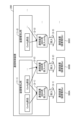
- Fig. 1 is a diagram for explaining a communication cutoff device 100 according to the present embodiment.
- the communication cutoff device 100 shown in Fig. 1 is an example of a computer that provides a technology for determining whether or not to cut off a specific communication between a communication device and a terminal device based on a setting status of the communication device in a communication network, and cutting off the communication determined to be cut off.
- the "specific communication” refers to any communication performed between an end user's terminal device and a communication device, and is not limited to a specific communication.
- the telecommunications carrier completes the work of connecting the physical wiring of the communication devices in advance, and then remotely configures the communication devices via a network controller.
- the above-mentioned communication settings may use Config, which is generated for each device type or target device.
- Config which is generated for each device type or target device.
- Figure 2 shows an example of Config settings according to this embodiment.
- the device that manages and controls the communication device (hereinafter, may be referred to as the "communication control device") mechanically combines Config components prepared in advance for each device type to generate and input Config for setting up communication for each communication device 300.
- the communication control device 200 stores a Config component for device type a and a Config component for device type b ((1-1) and (1-2) in FIG. 2). Then, when the communication control device 200 performs communication settings for the communication devices 300A to 300C, it generates an input Config for each communication device 300.
- Figure 3 is a diagram showing an example of the reference technology.
- Figure 3 shows a failure example ⁇ 1> in which a failure occurs in the system due to communication from the end user to the communication device 300 in progress, and a failure example ⁇ 2> in which the end user is cut off due to communication from the communication device in progress.
- failure example ⁇ 1> communication is performed from terminal device 400 to service providing server 600.
- communication from terminal device 400 is accommodated by communication device 300b in operation, and is connected to service providing server 600 via communication device 300b in operation and higher-level device 500b.
- communication device 300a in preparation is installed in the communication network as a new communication device, and communication settings are incomplete.
- the communication path shown in FIG. 3 (1-1) is normal because the communication is routed through the communication device 300b in operation.
- the communication path shown in FIG. 3 (1-2) the communication of the terminal device 400 is accommodated under the communication device 300a in progress. Then, the communication routed through the communication device 300a in progress is connected to the service providing server 600 via the higher-level device 500a and the higher-level device 500b (FIG. 3 (2)).
- terminal device 400 transmits a packet based on a broadcast to simultaneously communicate with communication devices 300 included in the communication network ((1-1) and (1-2) in FIG. 3).
- communication device 300a Upon receiving the packet, communication device 300a recognizes that terminal device 400 is under communication device 300a, and transmits this recognition to higher-level device 500, which causes the communication path to be recalculated and the communication path to be switched ((3) in FIG. 3).
- the service providing server 600 then communicates with the terminal device 400 to send a response ((4) in FIG. 3).
- the communication path is switched since the communication of the terminal device 400 is assumed to be under the control of the in-progress communication device 300a, and the communication is connected to the in-progress communication device 300a via the higher-level device 500b and higher-level device 500a.
- the in-progress communication device 300a is unable to send packets to the terminal device 400 because communication settings have not been completed, and a communication failure occurs ((5) in FIG. 3).
- failure example ⁇ 2> in which an end user is cut off due to communication from a communication device in progress.
- a user's terminal device 400, a communication device 300 that accommodates the communication of the terminal device 400, and a higher-level device 500 that accommodates each communication device are shown.
- the communication device 300 etc. performs IPv6 RA (Router Advertisement), which distributes information required for IPv6 address generation and default routes to the terminal device 400, and ARP (Address Resolution Protocol), which is a process for checking the correspondence between IP addresses and MAC addresses, etc.
- IPv6 RA Route Advertisement
- ARP Address Resolution Protocol
- the in-progress communication device 300a transmits packets related to IPv6 RA and ARP to the terminal device 400 ((7) in FIG. 3). Based on this, the terminal device 400 switches the packet transmission destination to the in-progress communication device 300a, so that the communication from the terminal device 400 is accommodated in the in-progress communication device 300a ((8) in FIG. 3). However, because the in-progress communication device 300a has not completed communication settings, it is unable to circulate the packets transmitted from the terminal device 400, and a communication failure occurs ((9) in FIG. 3).
- settings such as “do not send broadcasts” and “do not communicate with communication device 300a in progress” can be set based on a technology called vCPE, in which a communication carrier virtually provides and controls a communication device (CPE: Customer Premises Equipment) installed on the end user side.
- CPE Customer Premises Equipment
- the end user's communication network beyond the responsibility demarcation point may contain communication devices 300 that are not compatible with vCPE, making it difficult for the communication carrier to control everything.
- a different Config setting process than usual such as "enabling communication after Config setting is complete,” may be required, which may be difficult to apply from the perspective of strengthening the communication network or preventive maintenance.
- the communication cutoff device 100 updates the cutoff judgment conditions used to judge whether or not to cut off a specific communication between a communication device and a terminal device, based on the setting status of the communication device that accommodates communication from the terminal device.
- the communication cutoff device 100 judges whether or not a specific communication between a communication device and a terminal device is a communication to be cut off, based on the cutoff judgment conditions and information related to the specific communication.
- the above-mentioned communication cutoff process is realized by installing a communication cutoff device 100 between a terminal device 400 located on the end user side from the responsibility demarcation point (UNI) and a communication device 300 located on the telecommunications carrier side from the responsibility demarcation point (UNI).
- a communication cutoff device 100, a communication control device 200, a communication device 300, a terminal device 400, and a higher-level network are shown as an example on a specific communication network.
- the communication control device 200 controls the communication between the communication devices 300a and 300b (FIG. 1 (1-1)).
- the communication control device 200 also issues cutoff instructions and uncut instructions between the communication device 300 and the terminal device 400 to the communication cutoff device 100 (FIG. 1 (1-2)).
- the communication cutoff device 100 determines that the communication between the terminal device 400 and the communication device 300b in operation is not to be cut off ((2-1) in FIG. 1). On the other hand, the communication cutoff device 100 determines that the communication between the terminal device 400 and the communication device 300a in progress is to be cut off ((2-2) in FIG. 1).
- the communication cutoff device 100 updates the cutoff judgment conditions used to judge whether to cut off communication at a predetermined timing ((3-2) in FIG. 1) based on the setting status, such as when only planned installation is registered but not yet installed, when installation is complete but communication settings are not complete, or when a cutoff command is received from the communication control device 200 ((3-1) in FIG. 1).
- the communication cutoff device 100 uses the above-mentioned cutoff judgment conditions and information related to the specified communication, such as header information related to the communication between the terminal device 400 and the communication device 300a in progress, the interface number used, arbitrary information included in the packet, and the communication wavelength band, to judge whether the communication is to be cut off ((4-1) and (4-2) in FIG. 1).
- the communication cutoff device 100 determines that a specific communication between a terminal device 400 and a communication device 300 included in the communication network is to be cut off based on the setting status of the communication device 300 and the cutoff determination conditions. Therefore, the communication cutoff device 100 makes it easy to prevent the occurrence of unexpected communication with a communication device 300a that is in progress, etc.
- the communication cutoff device 100 updates the cutoff judgment condition based on the setting status of the communication device 300 received from the communication control device 200. Then, the communication cutoff device 100 determines whether or not the communication is a target for cutoff using the cutoff judgment condition and information related to a predetermined communication between the terminal device 400 and the communication device 300, and cuts off the target communication for cutoff.
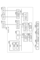
- Fig. 4 is a diagram showing an example of the configuration of the communication cutoff device 100 and the communication control device 200 according to the first embodiment.
- the communication cutoff device 100 has a communication unit 110, a storage unit 120, and a cutoff control unit 130.
- the communication cutoff device 100 can be provided with an input unit such as a keyboard or a mouse for receiving input such as operations by an administrator or the like.
- the communication cutoff device 100 can be provided with a display unit such as a display for displaying information related to communication cutoff such as a communication cutoff history and errors to an administrator or the like.
- the communication unit 110 performs data communication related to reception of packets and the like from a user's terminal device and reception of information on the setting status of the communication device from the communication control device 200 and information on a communication cutoff instruction or a communication cutoff release instruction.
- the communication unit 110 is realized by a NIC (Network Interface Card) or the like, and controls communication via an electric communication line such as a LAN (Local Area Network) or the Internet.
- the communication unit 110 is connected to a network by wire or wirelessly as necessary, and can transmit and receive information in both directions. For example, the communication unit 110 can perform two-way data communication with the communication unit 210 of the communication control device 200.
- the storage unit 120 stores data and programs used for various processes by the cutoff control unit 130, and various data acquired by the operation of the cutoff control unit 130.
- the storage unit 120 is realized by a semiconductor memory element such as a random access memory (RAM) or a flash memory, or a storage device such as a hard disk or an optical disk. As shown in FIG. 4, the storage unit 120 has a device status management DB 121.
- the device status management DB 121 is a database that stores cutoff judgment conditions and communication device registration information.
- the cutoff judgment conditions are conditions used by the cutoff control unit 130 (described later) to judge whether or not a communication is to be cut off.
- the communication device registration information is information about communication devices installed in a specific communication network, and is information used by the cutoff control unit 130 (described later) to judge whether or not a communication device in progress exists.
- the device status management DB121 stores, as blocking determination conditions, a No., the communication device side interface number of the communication blocking device, the terminal device side interface number of the communication blocking device, a VLAN ID, an EtherType, a source MAC address, a destination MAC address, a protocol number, a source IP address, a source port number, a destination IP address, a destination port number, and pass/block, each corresponding to one another.
- the above-mentioned No. is a unique number for identifying each of the blocking judgment conditions.
- the communication device side interface number of the communication blocking device is a number that identifies the interface through which the communication blocking device 100 connects to the carrier side communication device.
- the terminal device side interface number of the communication blocking device is a number that identifies the interface through which the communication blocking device 100 connects to the end user side terminal device.
- the VLAN ID is identification information that identifies each VLAN (Virtual LAN).
- the EtherType is identification information that identifies the type of communication protocol (type of network layer) to be transmitted.
- the source MAC address and destination MAC address are identification information that identify the device that is the source or destination of the packet.
- the protocol number, source IP address, source port number, destination IP address, and destination port number are information contained in the 5-tuple.
- Pass/block is information that indicates whether the communication that meets the above-mentioned conditions is passed or blocked.
- FIG. 5 is a table diagram showing an example of the blocking judgment condition according to the first embodiment.
- the device status management DB 121 stores, as blocking judgment conditions, the communication device side interface number of the communication blocking device "any", the terminal device side interface number of the communication blocking device "2", VLAN ID "any”, EtherType "any", source MAC address "any", destination MAC address "any", protocol number "any”, source IP address "any", source port number "any”, destination IP address "any”, destination port number "any”, pass/block “block”, etc., all of which are identified by No. "1".
- any is a character string that indicates a condition such as "any value is acceptable.”
- the blocking judgment condition identified by No. “1” means that if the interface number on the terminal device side of the communication blocking device is "2,” then “the communication is judged to be a target for blocking” regardless of the values of the other items.
- the blocking judgment condition identified by No. “2” means that if the interface number on the communication device side of the communication blocking device is "1,” then “the communication is judged to be a pass-through (not a target for blocking)” regardless of the values of the other items.
- the device status management DB 121 can also store information related to optical communications, including, for example, LLID or communication wavelength bands.
- the device status management DB 121 stores, as communication device registration information, a number, the communication device side interface number of the communication cutoff device, and a VLAN ID, each associated with each other. Note that the above-mentioned number is a unique number for identifying each piece of information in the communication device registration information.
- FIG. 6 is a table diagram showing an example of communication device registration information according to the first embodiment.
- device status management DB 121 stores, as communication device registration information, the communication device side interface number "1" of the communication cutoff device identified by No. "1", VLAN ID "any”, etc.
- any is a character string that indicates the condition "any value is acceptable.” In other words, it means that the communication device is connected to the interface identified by the interface numbers "1," "2,” and "3" on the communication cutoff device's communication device side as the communication device registration information identified by No. "1.”
- the cutoff control unit 130 has an internal memory for temporarily storing a program defining the cutoff processing procedure of the communication cutoff device 100 and processing data, and is realized by electronic circuits such as a CPU (Central Processing Unit) and an MPU (Micro Processing Unit), and integrated circuits such as an ASIC (Application Specific Integrated Circuit) and an FPGA (Field Programmable Gate Array). As shown in FIG. 4, the cutoff control unit 130 has a reception unit 131, an update unit 132, a determination unit 133, and a cutoff unit 134.
- the receiving unit 131 receives information transmitted from an external device and stores it in the storage unit 120 .
- the reception unit 131 receives packets sent from the end user's terminal device and stores the header information and the like contained in the packets.
- the reception unit 131 also receives and stores information related to a specific communication, such as a port number and an interface number, collected from a communication device and the like.
- the reception unit 131 also receives and stores registration information (communication device registration information) related to communication devices installed in the communication network from the communication control device 200.
- the reception unit 131 also receives and stores information such as a specific communication blocking instruction or a blocking release instruction output from the communication control device 200. Note that the reception unit 131 is not limited to the above-mentioned information, and can receive any information related to communication blocking processing.
- the update unit 132 updates the blocking judgment condition used to judge whether or not to block a specific communication between a communication device and a terminal device, based on the setting status of the communication device that accommodates the communication from the terminal device.
- the "setting status of the communication device” includes setting statuses such as: only the planned installation is registered but not yet installed; installation is completed but communication setting is not yet completed; there is an instruction to set blocking or release blocking from the communication control device 200; and a setting is made to block or pass specific communication related to the communication device.
- the update unit 132 updates the blocking judgment conditions so that the communication device is judged to be a target for blocking. For example, when information on the setting status such as "communication setting is incomplete for the communication device 300 connected to the terminal device side interface number "2" of the communication blocking device” or "communication blocking is implemented for the communication device connected to the terminal device side interface number "2" of the communication blocking device" is received from the communication control device 200, the update unit 132 updates the pass/block item to "block" for the blocking judgment condition identified by No. "1" in FIG. 5 so that it is judged that the specified communication related to the communication device is a target for blocking.
- the update unit 132 updates the blocking judgment conditions so that the communication device is judged not to be blocked when at least one of the communication settings is completed or an instruction to cancel the blocking setting is received. For example, when information on the setting status such as "communication settings are completed for the communication device connected to the terminal device side interface number "2" of the communication blocking device” or "communication blocking for the communication device connected to the terminal device side interface number "2" of the communication blocking device is canceled" is received from the communication control device 200, the update unit 132 updates the pass/block item to "pass" for the blocking judgment condition identified by No. "1" shown in FIG. 5 so that it is judged that the specified communication related to the communication device is not to be blocked.
- the determination unit 133 determines whether or not the predetermined communication between the communication device and the terminal device is a communication to be blocked, based on the blocking determination condition updated by the update unit 132 and information on the predetermined communication between the terminal device 400 and the communication device. For example, the determination unit 133 determines that the communication is a communication to be blocked when the information on the predetermined communication satisfies a blocking determination condition including one or more combinations of an interface number, 5 tuple, arbitrary information included in a packet such as a VLAN ID and Ether Type, and information on optical communication including an LLID or a communication wavelength band.
- the determination unit 133 determines that a communication is to be blocked when information about a specific communication between a communication device and a terminal device satisfies a combination of communication targets included in a preset blocking determination condition. For example, when information about a specific communication between a communication device and a terminal device includes information such as "Terminal device side interface number of communication blocking device: 2", the determination unit 133 determines that the communication is to be blocked based on the blocking determination condition identified by No. "1" described in FIG. 5. Furthermore, based on information about optical communication including an LLID or a communication wavelength band, the determination unit 133 determines that communication using an optical wavelength other than the specified optical wavelength is to be blocked when optical communication is carried out using a certain optical wavelength.
- the determination unit 133 determines that the communication is to be blocked when the information about the specified communication does not include registration information of a communication device installed in the communication network. For example, when the information about the specified communication between a communication device and a terminal device includes information such as "Terminal device side interface number of communication blocking device: 4", the determination unit 133 determines that the communication is to be blocked because the corresponding interface number is not included in the communication device registration information described in FIG. 6.
- the cutoff unit 134 cuts off a communication that is determined by the determination unit 133 to be a communication to be cut off. Specifically, the cutoff unit 134 performs cutoff processing such as discarding packets or not transmitting packets for a communication including the "terminal device side interface number of the communication cutoff device: 2" that is determined by the determination unit 133 to be a communication to be cut off.
- the communication control device 200 is an example of an information processing device that controls the communication device and the like using Config and issues an instruction to the communication cutoff device 100 to perform or release cutoff.
- the communication control device 200 has a communication unit 210, a storage unit 220, a control unit 230, and a cutoff control unit 240.
- the communication control device 200 can be provided with an input unit such as a keyboard or a mouse for receiving input such as operations by an administrator.
- the communication control device 200 can be provided with a display unit such as a display for displaying information related to communication cutoff such as the history and results of communication control, errors, etc. to the administrator.
- the communication unit 210 performs data communication such as issuing instructions to the communication cutoff device 100 to cut off or release the cutoff of communication, and inputting configuration information to the communication device.
- the communication unit 210 is realized by a NIC or the like, and controls communication via an electric communication line such as a LAN or the Internet.
- the communication unit 210 is connected to the communication cutoff device 100 or the communication device or the like via a wired or wireless network as necessary, and can transmit and receive information in both directions.
- the storage unit 220 stores data and programs used for various processes by the control unit 230, and various data acquired by the operation of the control unit 230.
- the storage unit 220 is realized by a semiconductor memory element such as a RAM or a flash memory, or a storage device such as a hard disk or an optical disk. As shown in FIG. 4, the storage unit 220 has a config storage DB 221.
- the Config storage DB 221 is a database that stores Config components (templates) used by a Config generation unit 231 (described later) and generated input Configs.
- the control unit 230 has an internal memory for temporarily storing programs and processing data that define various processing procedures of the communication control device 200, and is realized by electronic circuits such as a CPU and an MPU, and integrated circuits such as an ASIC and an FPGA. As shown in FIG. 4, the control unit 230 has a config generation unit 231 and a config input unit 232.
- the Config generation unit 231 generates an input Config for a Config corresponding to each communication device to be controlled by combining Config components stored in the Config storage DB 221.
- the Config generation unit 231 can generate the input Config using a known method.
- the Config input unit 232 performs communication settings by inputting the input Config generated by the Config generation unit 231 to each communication device to be controlled. For example, when the Config input unit 232 receives an instruction to input a Config from the control unit 230 of the communication control device 200, the Config input unit 232 inputs the generated Config to the target communication device to perform communication settings.
- the cutoff control unit 240 has an internal memory for temporarily storing a program that defines the cutoff processing procedure of the communication control device 200 and processing data, and is realized by an electronic circuit such as a CPU or an MPU, or an integrated circuit such as an ASIC or an FPGA.
- the cutoff control unit 240 has a cutoff setting instruction unit 241 as shown in FIG.
- the cutoff setting instruction unit 241 instructs the communication cutoff device 100 to cut off or release a cutoff of a predetermined communication between a communication device and a terminal device.
- the blocking setting instruction unit 241 when the Config setting for a communication device in progress is completed, the blocking setting instruction unit 241 outputs an instruction to the communication blocking device 100 to "cancel blocking.” On the other hand, when a Config to be applied to a communication device in progress has been generated but the Config setting has not been completed, the blocking setting instruction unit 241 outputs an instruction to the communication blocking device 100 to "perform blocking.”
- the blocking setting instruction unit 241 outputs an instruction to "block" a specific communication between the communication device and an end user's terminal device, etc., based on the operation of an administrator, etc.
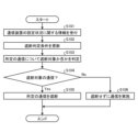
- Fig. 7 is a diagram showing an example of a flowchart of the communication cutoff method according to the first embodiment. Note that each step may be interchanged and executed within a range where there is no contradiction, and there may be steps that are not executed.
- the reception unit 131 receives information related to the setting status of the communication device (S101).
- the update unit 132 updates the blocking judgment conditions based on the received information related to the setting status of the communication device (S102).
- the determination unit 133 determines whether or not a specific communication between the terminal device and the communication device is to be blocked (S103). If it is determined that the communication is to be blocked (Yes in S104), the blocking unit 134 blocks the specific communication determined to be to be blocked (S105). Then, the communication blocking device 100 ends the process.
- the communication blocking device 100 continues the communication without blocking it (S106). Then, the communication blocking device 100 ends the process.
- effect Hereinafter, a description will be given of the effects provided by the communication cutoff device 100 according to the first embodiment.
- a problem that has been encountered up until now is that it may be difficult to prevent the occurrence of unexpected communication with a communication device that is in process.
- the update unit 132 of the communication cut-off device 100 updates the cut-off judgment conditions used to judge whether or not to cut off a specific communication between a communication device and a terminal device, based on the setting status of the communication device that accommodates communication from the terminal device.
- the judgment unit 133 of the communication cut-off device 100 judges whether or not the communication between the communication device and the terminal device is communication to be cut off, based on the cut-off judgment conditions and information related to the specific communication. Therefore, the communication cut-off device 100 according to the first embodiment has the effect of making it possible to cut off unexpected communication between a communication device and a terminal device.
- the determination unit 133 determines that the communication is to be blocked when the information about the specified communication satisfies a blocking determination condition that includes one or a combination of the following: an interface number, 5tuple, arbitrary information contained in the packet such as VLAN ID and EtherType, and information about optical communication including an LLID or communication wavelength band.
- a blocking determination condition that includes one or a combination of the following: an interface number, 5tuple, arbitrary information contained in the packet such as VLAN ID and EtherType, and information about optical communication including an LLID or communication wavelength band.
- the determination unit 133 determines that the communication is to be blocked when the information relating to the specified communication does not include registration information for a communication device installed in the communication network.
- the communication blocking device 100 determines whether the specified communication related to the communication device is to be blocked based on whether the communication device is registered in the communication control device 200 or the like. Therefore, when a communication device is newly added to the communication network but its information is not registered and it is unusable, the communication blocking device 100 can determine that the communication with the communication device is to be blocked. Furthermore, the communication blocking device 100 can detect an unknown communication device whose information is not registered, and determine that the communication with the communication device is to be blocked.
- the communication cutoff device 100 performs cutoff processing for a specific communication between a target communication device and a terminal device based on cutoff judgment conditions that are updated according to the setting status of the communication device.
- the communication cutoff device 100 can prevent an in-progress communication device from performing unexpected operations by preventing unnecessary packets from reaching the in-progress communication device from the end user side.
- the communication cutoff device 100 can prevent an in-progress communication device from being cut off due to the interception of the end user's communications, by preventing the end user's terminal device from detecting the presence of a newly installed device.
- the communication cutoff device 100 can flexibly control the determination of communication to be cut off using interface numbers, 5 tuples, VLAN IDs, EtherTypes, etc., so it can appropriately determine and cut off communication to be cut off even when the communication cutoff device 100 and the communication device in progress are not directly connected or when multiple VLANs are superimposed on one interface by VLANs for each end user.
- the communication blocking device 100 can block specific communications, it can block all communications or only a portion of the communications. Therefore, in cases where the communication device in progress is designed to prepare for switching in advance or where the end user's terminal device is designed to automatically switch communication paths, the communication blocking device 100 blocks only the communications from the communication device in progress to the end user's terminal device and allows the reverse communications to pass, making it possible to quickly switch paths after the communication settings of the communication device are complete.
- the communication cutoff device 100 can prevent communication failures that may occur when an end user's terminal device uses an unexpected optical wavelength by cutting off communications at any wavelength other than the specified optical wavelength.
- the communication blocking device 100 automatically changes the communications to be blocked in accordance with changes in the settings of the communication device, thereby reducing the amount of computer processing required to determine which communications should be blocked.
- the communication control device 200 performs the process of updating the blocking judgment conditions in the first embodiment and determining whether a specific communication is to be blocked or not, and outputs a blocking instruction to the communication blocking device 100, thereby blocking the communication to be blocked.
- Fig. 8 is a diagram showing an example of the configuration of the communication cutoff device 100 and the communication control device 200 according to the second embodiment.
- the communication cutoff device 100 has a communication unit 110, a storage unit 120, and a cutoff control unit 130. Since the communication cutoff device 100 according to the second embodiment has the same functions as the communication cutoff device 100 according to the first embodiment, the communication unit 110, the storage unit 120, etc., whose functions overlap between the first embodiment and the second embodiment, will be appropriately omitted in the description.
- the cutoff control unit 130 includes a reception unit 131 , a cutoff unit 134 , and a query unit 135 .
- the receiving unit 131 receives information such as a cutoff instruction or a cutoff release instruction for a predetermined communication output from the communication control device 200 .
- the cutoff unit 134 cuts off communication to be cut off based on a predetermined communication cutoff instruction output from the communication control device 200 received by the reception unit 131. Specifically, the cutoff unit 134 performs cutoff processing such as discarding packets or not transmitting packets for communication including "terminal device side interface number of communication cutoff device: 2" determined by the communication control device 200 as a communication to be cut off. On the other hand, when a cutoff release instruction is output from the communication control device 200, the cutoff unit 134 does not perform cutoff processing.
- the communication control device 200 has a communication unit 210, a storage unit 220, a control unit 230, and a cutoff control unit 240. Note that since the communication control device 200 according to the second embodiment has the same functions as the communication control device 200 according to the first embodiment, the communication unit 210, the storage unit 220, and the control unit 230, whose functions overlap between the first embodiment and the second embodiment, will be described in abbreviated form as appropriate.
- the cutoff control unit 240 has a cutoff setting instruction unit 241, a reception unit 242, an update unit 243, and a determination unit 244.
- the reception unit 242 has the same function as the reception unit 131 according to the first embodiment
- the update unit 243 has the same function as the update unit 132 according to the first embodiment, and therefore the description thereof will be omitted in this section.
- the cutoff setting instruction unit 241 instructs the communication cutoff device 100 to cut off or release a cutoff of a predetermined communication between a communication device and a terminal device based on a determination result of a determination unit 244 described later.
- the judgment unit 244 judges whether the communication between the communication device and the terminal device is communication to be blocked based on the blocking judgment conditions updated by the update unit 243, information regarding specific communication related to the communication between the terminal device and the communication device, and information regarding the setting status of the communication device.
- Fig. 9 is a sequence diagram for explaining an example of communication cutoff processing according to the second embodiment.
- Fig. 9 explains (1) before installation of the communication device 300, (2) when installing the communication device 300, (3) after installation of the communication device 300 and before completion of setting, (4) setting of the communication device 300, and (5) after installation of the communication device 300 and after completion of setting.
- the communication cutoff device 100 queries the cutoff control unit 240 about cutoff (S1-1).
- the cutoff control unit 240 refers to the communication device registration information stored in the device status management DB 222 (S1-2).
- the device status management DB 222 does not store communication registration information for the target communication device 300 (S1-3). Therefore, the cut-off control unit 240 instructs the communication cut-off device 100 to cut off specific communications between the communication device 300 and terminal devices, etc. (S1-4). The communication cut-off device 100 then cuts off the specific communications (S1-5).
- the cutoff control unit 240 Based on instructions from the control unit 230, the cutoff control unit 240 performs cutoff registration to update the cutoff determination conditions so as to set the cutoff setting for the communication device 300 (S2-3).
- the communication cutoff device 100 queries the cutoff control unit 240 about cutting off (S3-1).
- the cutoff control unit 240 refers to the communication device registration information stored in the device status management DB 222 (S3-2).
- the device status management DB 222 stores the communication registration information and cut-off judgment conditions of the target communication device 300 (S3-3). Then, based on the communication registration information and the cut-off judgment conditions, the cut-off control unit 240 instructs the communication cut-off device 100 to cut off a specific communication between the communication device 300 and a terminal device or the like (S3-4). Then, the communication cut-off device 100 cuts off the specific communication (S3-5).
- the control unit 230 instructs the cutoff control unit 240 to set the communication device to cutoff (S4-4). Then, based on the instruction from the control unit 230, the cutoff control unit 240 performs cutoff registration to update the cutoff determination conditions so as to set the communication device 300 to cutoff (S4-5).
- the device status management DB 222 stores the cutoff judgment condition registered as "cutoff performed" for the target communication device 300 (S4-6). Then, the cutoff control unit 240 instructs the communication cutoff device 100 to cut off specific communications between the communication device 300 and a terminal device, etc., based on the cutoff judgment condition (S4-7). The communication cutoff device 100 then cuts off the specific communications (S4-8). The cutoff control unit 240 also notifies the control unit 230 that the cutoff has been completed (S4-9).
- the control unit 230 which has received the cutoff completion notification, issues an instruction to input the generated input Config (S4-10).
- the Config input unit 232 then obtains the input Config stored in the Config storage DB 221 (S4-11) and inputs the Config to the target communication device 300 (S4-12).
- the communication device 300 reflects the input config (S4-13) and notifies the control unit 230 that the config has been input (S4-14).
- the control unit 230 which has received the notification that Config has been entered, instructs the cutoff control unit 240 to unblock the specified communications related to the communication device 300 (S4-15). Then, based on the instruction from the control unit 230, the cutoff control unit 240 performs cutoff unblocking registration, which updates the cutoff judgment conditions so as to unblock the communication device 300 (S4-16).
- the device status management DB 222 stores the "unblocked" status of the target communication device 300 and the registered blocking judgment condition (S4-17). Based on the blocking judgment condition, the blocking control unit 240 then instructs the communication blocking device 100 to block specific communications between the communication device 300 and a terminal device or the like (S4-18). The communication blocking device 100 then unblocks the specific communications (S4-19). The blocking control unit 240 also notifies the control unit 230 of the completion of the blocking unblocking registration (S4-20).
- the communication cutoff device 100 queries the cutoff control unit 240 about cutting off (S5-1).
- the cutoff control unit 240 refers to the communication device registration information stored in the device status management DB 222 (S5-2).
- the device status management DB 222 stores the cutoff judgment condition for the target communication device 300, with the information updated to "cutoff released" (S5-3). Then, the cutoff control unit 240 instructs the communication cutoff device 100 to release the cutoff of a specific communication between the communication device 300 and a terminal device, etc., based on the cutoff judgment condition (S5-4). Then, the communication cutoff device 100 releases the cutoff setting for the specific communication (S5-5).
- the communication cutoff process according to the second embodiment can be realized by being separated into a plurality of devices, namely, the communication cutoff device 100 and the communication control device 200. Therefore, the communication cutoff process can be realized based on a flexible device configuration without being limited by the configuration or constraints of the communication network.
- the items of the blocking judgment conditions such as No, the communication device side interface number of the communication blocking device, the terminal device side interface number of the communication blocking device, the VLAN ID, the EtherType, the source MAC address, the destination MAC address, the protocol number, the source IP address, the source port number, the destination IP address, the destination port number, and pass/block, which are stored in the device status management DB121 or the device status management DB221, etc., can be changed as desired.
- the items of the communication device registration information stored in device status management DB121 or device status management DB221, such as the No., the communication device side interface number of the communication cutoff device, and the VLAN ID, can be changed as desired.
- the process related to blocking is described as being performed by the communication blocking device 100 in the first embodiment and by the communication blocking device 100 and the communication control device 200 in the second embodiment, the present invention is not limited to this.
- a functional unit that executes the process related to blocking may be implemented in another information processing device having a function different from that of the communication blocking device 100 and the communication control device 200.
- the communication cutoff device 100 has been described as being configured to be directly connected to the end user's terminal device or communication device, but this is not limited to this and the device may be installed at any location on the communication path between the end user's terminal device and the communication device.
- a communication device having the function of blocking specified communications may be placed in place of the communication blocking device 100.
- the communication cutoff device 100 cuts off a predetermined communication between the terminal device 400 and the communication device 300, but the target communication is not particularly limited.
- the communication cutoff device 100 or the communication control device 200 may cut off the predetermined communication as "all communication between the communication device in progress and the terminal device on the end user side", or "only communication including predetermined destination information", "only communication among broadcasts that reaches the communication device in progress", “only communication related to RA or ARP from the communication device in progress”, etc.
- each component of each device shown in the figure is a functional concept, and does not necessarily have to be physically configured as shown in the figure.
- the specific form of distribution and integration of each device is not limited to that shown in the figure.
- all or part of them can be functionally or physically distributed and integrated in any unit depending on various loads, usage conditions, etc.
- each component of each device shown in the figure is a functional concept, and does not necessarily have to be physically configured as shown in the figure.
- the specific form of distribution and integration of each device is not limited to that shown in the figure, and all or a part of it can be functionally or physically distributed and integrated in any unit depending on various loads, usage conditions, etc.
- each processing function performed by each device can be realized in whole or in any part by a CPU and a program analyzed and executed by the CPU, or can be realized as hardware using wired logic.
- the various devices constituting the communication cutoff device 100 and the communication control device 200 can be implemented by installing a communication cutoff program as package software or online software on a desired computer.
- the above-mentioned communication cutoff program can be executed by an information processing device to function as various devices constituting the communication cutoff device 100 and the communication control device 200.
- the information processing device here includes desktop or notebook personal computers.
- the information processing device also includes mobile communication terminals such as smartphones and mobile phones, and slate terminals such as PDAs (Personal Digital Assistants).
- FIG. 10 is a diagram showing an example of a computer that executes the communication cutoff process according to this embodiment.
- the computer 1000 has, for example, a memory 1010 and a CPU 1020.
- the computer 1000 also has a hard disk drive interface 1030, a disk drive interface 1040, a serial port interface 1050, a video adapter 1060, and a network interface 1070. Each of these components is connected by a bus 1080.
- the memory 1010 includes a ROM (Read Only Memory) 1011 and a RAM 1012.
- the ROM 1011 stores a boot program such as a BIOS (Basic Input Output System).
- BIOS Basic Input Output System
- the hard disk drive interface 1030 is connected to a hard disk drive 1090.
- the disk drive interface 1040 is connected to a disk drive 1100.
- a removable storage medium such as a magnetic disk or optical disk is inserted into the disk drive 1100.
- the serial port interface 1050 is connected to a mouse 1110 and a keyboard 1120, for example.
- the video adapter 1060 is connected to a display 1130, for example.
- the hard disk drive 1090 stores, for example, an OS 1091, an application program 1092, a program module 1093, and program data 1094. That is, the programs that define the processes of the various devices that constitute the communication cutoff device 100 and the communication control device 200 are implemented as program modules 1093 in which computer-executable code is written.
- the program modules 1093 are stored, for example, in the hard disk drive 1090.
- the program modules 1093 for executing processes similar to the functional configurations of the various devices that constitute the communication cutoff device 100 and the communication control device 200 are stored in the hard disk drive 1090.
- the hard disk drive 1090 may be replaced by an SSD (Solid State Drive).
- the setting data used in the processing of the above-mentioned embodiment is stored as program data 1094, for example, in memory 1010 or hard disk drive 1090.
- the CPU 1020 reads out the program module 1093 or program data 1094 stored in memory 1010 or hard disk drive 1090 into RAM 1012 as necessary, and executes the processing of the above-mentioned embodiment.
- the program module 1093 and program data 1094 are not limited to being stored in the hard disk drive 1090, but may be stored in a removable storage medium, for example, and read by the CPU 1020 via the disk drive 1100 or the like. Alternatively, the program module 1093 and program data 1094 may be stored in another computer connected via a network (such as a LAN or a WAN (Wide Area Network)). The program module 1093 and program data 1094 may then be read by the CPU 1020 from the other computer via the network interface 1070.
- a network such as a LAN or a WAN (Wide Area Network)
Landscapes
- Engineering & Computer Science (AREA)
- Computer Networks & Wireless Communication (AREA)
- Signal Processing (AREA)
- Data Exchanges In Wide-Area Networks (AREA)
Abstract
通信遮断装置(100)は、端末装置からの通信を収容する通信装置の設定状況に基づき、通信装置と端末装置との所定の通信を遮断するか否かの判定に用いる遮断判定条件を更新する。通信遮断装置(100)は、遮断判定条件と所定の通信に関する情報に基づき、通信装置と端末装置との所定の通信が遮断対象の通信か否かを判定する。
Description
本発明は、通信網を構成する装置へ設定を投入する際のトラヒックを制御する通信遮断装置に関する。
通信事業者の提供するIP(Internet Protocol)網等の通信網は、大量かつ多種多様な通信装置を用いて構成されている。当該通信装置を管理制御するNW(Net Work)コントローラ等の装置は、通信網の構築や復旧のために通信装置ごとの設定情報(以降、「Config」と表記する場合がある)の部品を適宜組み合わせて機械的にConfigを生成して、Configを変更する。
そのため、通信事業者は、上述の増強や予防保全を実施する場合、予め通信装置等の物理配線接続等の作業を完了させた上で、NWコントローラを経由して遠隔でConfigを当該通信装置に投入する。その結果、通信設定が未完了の仕掛中の通信装置が、一時的に通信網に接続される場合がある。
通信事業者が通信網の増強や予防保全の実施を行う際には、エンドユーザ側に影響を与えずに実施することが求められるにも関わらず、仕掛中の通信装置と端末装置との予期せぬ通信に起因して通信網に障害が発生したり、エンドユーザと通信装置との通信が不通となったりする可能性がある。そこで、vCPE(virtual Customer Premises Equipment)等の技術に基づいて、エンドユーザ側の装置を仮想的に提供および制御することで所定の通信を制御する技術(非特許文献1)が知られている。また、通信事業者による保守作業の際に、特定の通信装置から異なる通信装置へエンドユーザ側の装置を収容しなおす技術が知られている(例えば、非特許文献2を参照)。
井上寛規,奥川徹,増田暁生,vCPEにおけるWAN高速化機能仮想化の実用性評価,信学技報,2014年4月10日,Vol.114 No.6,pp.125~130.
細野浩輝,井上寛規,阿部真司,須藤篤史,新原康之,ネットワーク装置の段階的移行方式に関する一検討,2022年電子情報通信学会総合大会,2022年3月1日,B-6-67
しかしながら、従来技術では、通信装置と端末装置との予期しない通信を遮断することが困難な場合がある、という課題がある。例えば、従来技術では、責任分界点(UNI:User Network Interface)の先に存在し得る装置を全て想定して適切な制御を行うことは困難である。
また、例えば、従来技術に基づいて所定の通信を制御するとしても、通信装置は、通信装置による予期しない通信を防ぐために通信遮断設定を実施した上で、通信に必要なConfigを変更して、その後に自身の通信遮断設定を解除する等のConfig変更手順が可能である必要がある。しかし、通信網に含まれる通信装置が上述した機能を必ずしも有するわけではなく、実際には参考技術に基づいて制御を行うことが難しい場合がある。
そこで、上記の課題を解決し目的を達成するために、本発明の通信遮断装置は、端末装置からの通信を収容する通信装置の設定状況に基づき、前記通信装置と前記端末装置との所定の通信を遮断するか否かの判定に用いる遮断判定条件を更新する更新部と、前記遮断判定条件と前記所定の通信に関する情報に基づき、前記通信装置と前記端末装置との前記所定の通信が遮断対象の通信か否かを判定する判定部と、を有することを特徴とする。
本発明は、通信装置と端末装置との予期しない通信の遮断実施を可能とする、という効果を奏する。
以下、図面を参照しながら、本発明を実施するための形態(以降、「実施形態」)について説明する。なお、各実施形態は、以下に記載する内容に限定されない。
<通信制御装置の説明>
図1は、本実施形態に係る通信遮断装置100を説明する図である。図1に示す通信遮断装置100は、通信網における通信装置の設定状況に基づき当該通信装置と端末装置との所定の通信を遮断するか否かを判定し、遮断対象と判定された通信について遮断する技術を提供するコンピュータの一例である。なお、本実施形態において「所定の通信」とは、エンドユーザ側の端末装置と通信装置との間で行われる任意の通信であり、特定の通信に限定されない。
図1は、本実施形態に係る通信遮断装置100を説明する図である。図1に示す通信遮断装置100は、通信網における通信装置の設定状況に基づき当該通信装置と端末装置との所定の通信を遮断するか否かを判定し、遮断対象と判定された通信について遮断する技術を提供するコンピュータの一例である。なお、本実施形態において「所定の通信」とは、エンドユーザ側の端末装置と通信装置との間で行われる任意の通信であり、特定の通信に限定されない。
従来、通信事業者の提供するIP網等の通信網について、通信事業者が増強や予防保全の実施を行う場合、エンドユーザ側に影響を与えずに実施することが求められる。そのため、通信事業者は、予め通信装置等の物理配線接続等の作業を完了させた上で、NWコントローラを経由して遠隔で通信装置の設定を行う。
上述した通信設定には、装置種別や対象の装置ごとに生成されるConfigが用いられる場合がある。ここで、Configを用いた通信装置の設定について説明する。図2は、本実施形態に係るConfig設定の一例を示す図である。
当該通信装置を管理制御する装置(以降、「通信制御装置」と記載する場合がある)は、装置種別ごとに予め準備されたConfig部品を機械的に組み合わせて、通信装置300ごとの通信設定を行うための投入Configを生成して、投入する。
例えば、図2に示すように、通信制御装置200は、装置種別a用のConfig部品と、装置種別b用のConfig部品とを記憶する(図2の(1-1)および(1-2))。そして、通信制御装置200は、通信装置300Aから300Cに対して通信設定を行う際に、各通信装置300に合わせて投入Configを生成する。
具体的には、通信制御装置200は、装置種別a用の複数のConfig部品を組み合わせて、装置種別aの通信装置300Aおよび通信装置300B用の投入Configを生成する(図2の(2-1)および(2-2))。また、通信制御装置200は、装置種別b用の複数のConfig部品を組み合わせて、装置種別bの通信装置300C用の投入Configを生成する(図2の(2-3))。
通信制御装置200は、通信装置300Aに対しては通信装置300A用の投入Configを、通信装置300Bに対しては通信装置300B用の投入Configを、通信装置300Cに対しては通信装置300C用の投入Configを、それぞれ投入する(図2の(3-1)から(3-3))。
上述したConfig生成および投入により遠隔で通信装置の設定を実施することができるが、通信網の増強や予防保全を行う場合には物理的に通信装置を追加するため、通信設定未完了の仕掛中の通信装置が一時的に通信網に接続される場合がある。このような場合、仕掛中の通信装置に対して通信が行われると予期せぬ動作に起因して通信網に障害が発生したり、エンドユーザと通信装置との通信が不通となったりする可能性がある。あるいは、仕掛中の通信装置からエンドユーザ側へパケットが送信されることでエンドユーザ側の端末装置が新規導入装置の存在を検知してしまい、準備完了前の通信装置がエンドユーザの通信を横取りし、結果として不通になる可能性がある。
ここで、上述した障害の一例について説明を行う。図3は、参考技術の一例を示す図である。図3には、エンドユーザ側から仕掛中の通信装置300への通信により系に障害が発生する障害例<1>と、仕掛中の通信装置からの通信によりエンドユーザが不通になる障害例<2>とが示されている。
まず、エンドユーザ側から仕掛中の通信装置300への通信により系に障害が発生する障害例<1>について説明する。図3の障害例<1>には、エンドユーザの端末装置400と、端末装置400の通信を収容する通信装置300と、各通信装置を収容する上位装置500と、サービス提供サーバ600とが示されている。そして、通信事業者側とエンドユーザ側とは、UNIにて分界される。
なお、通信装置300は、通信設定が未完了等で通信の実施に制限がある仕掛中の通信装置(以降、単に「仕掛中の通信装置」と表記する場合がある)300aと、通信設定が完了済みで運用中の通信装置(以降、単に「運用中の通信装置」と表記する場合がある)300bを含む。また、上位装置500は、仕掛中の通信装置300aを収容する上位装置500aと運用中の通信装置300bを収容する上位装置500bとを含む。
障害例<1>に示す事例では、端末装置400からサービス提供サーバ600に対して通信が行われる。障害例<1>において正常な通信が行われている状況では、端末装置400の通信は、運用中の通信装置300bに収容され、当該運用中の通信装置300b、上位装置500bを経由して、サービス提供サーバ600へと接続される。他方、仕掛中の通信装置300aは、新しい通信装置として当該通信網に設置され、通信設定が未完了である。
図3の(1-1)に示す通信経路は、運用中の通信装置300bを経由する通信のため正常に通信が行われる。他方、図3の(1-2)に示す通信経路が使用された場合、端末装置400の通信は、仕掛中の通信装置300aの配下に収容される。そして、仕掛中の通信装置300aを経由する通信は、上位装置500a、上位装置500bを経由してサービス提供サーバ600へと接続される(図3の(2))。
ここで、端末装置400が、通信網に含まれる通信装置300に対して同時に通信を行うブロードキャストに基づきパケットを送信した場合を考える(図3の(1-1)および(1-2))。通信装置300aは該パケットの着信を契機として、端末装置400は通信装置300aの配下に収容されているものと認識し、上位装置500へ該収容認識を伝達することで通信経路の再計算が行われ、通信経路が切り替えられる(図3の(3))。
次に、サービス提供サーバ600は、端末装置400に対して返答のための通信を行う(図3の(4))。この時、端末装置400の通信が仕掛中の通信装置300aの配下に収容されているものとして通信経路が切り替えられたことから、当該通信は、上位装置500b、上位装置500aを経由して、仕掛中の通信装置300aへと接続される。ここで、仕掛中の通信装置300aは、通信設定が完了していないため端末装置400に対してパケットを送信することができず、通信障害が発生する(図3の(5))。
次に、仕掛中の通信装置からの通信によりエンドユーザが不通になる障害例<2>について説明する。図3の障害例<2>には、ユーザの端末装置400と、端末装置400の通信を収容する通信装置300と、各通信装置を収容する上位装置500とが示されている。障害例<2>に示す事例では、通信装置300等が端末装置400にIPv6アドレス生成に必要な情報やデフォルトルートを配布するIPv6 RA(Router Advertisement)や、IPアドレスとMACアドレスの対応を調べる処理であるARP(Address Resolution Protocol)等が行われる。
障害例<2>において正常な通信が行われている状況では、端末装置400の通信は、運用中の通信装置300bに収容され、当該運用中の通信装置300b、上位装置500bへと接続される(図3の(6))。他方、仕掛中の通信装置300aは、新しい通信装置として当該通信網に設置され、通信設定が未完了である。
ここで、仕掛中の通信装置300aは、端末装置400に対してIPv6 RAやARPに係るパケットを送信する(図3の(7))。それに基づいて、端末装置400は、パケット送信先を仕掛中の通信装置300aに切り替えることで、端末装置400からの通信が仕掛中の通信装置300aに収容される(図3の(8))。しかし、仕掛中の通信装置300aは通信設定が完了していないため、端末装置400から送信されたパケットを流通させることができず、通信障害が発生する(図3の(9))。
上述したような通信障害に対して、エンドユーザ側の端末装置400を仮想的に提供および制御するvCPE等の技術に基づいて、対象の通信装置300に通信を行わないような設定の実施や、所定の通信装置300から異なる通信装置300へエンドユーザ側の端末装置400を収容しなおす参考技術が知られている。
上述したような参考技術では、エンドユーザ側に設置された通信装置(CPE:Customer Premises Equipment)を通信事業者が仮想的に提供、制御するvCPEという技術に基づいて、「ブロードキャストを送信しない」、「仕掛中の通信装置300aに通信しない」等の設定を行うことができる。
しかし、実際には、責任分界点(UNI)の先のエンドユーザ側の通信網上にはvCPEに適合しない通信装置300も含まれている場合があり、通信事業者側から全てを制御するのは困難である。また、エンドユーザ側の端末装置400を収容しなおす場合でも、「Config設定が完了した後に通信を可能とする」等の通常とは異なるConfig設定処理が必要となり、通信網の増強や予防保全の観点から適用が難しい場合がある。
そこで、本実施形態に係る通信遮断装置100は、端末装置からの通信を収容する通信装置の設定状況に基づき、通信装置と端末装置との所定の通信を遮断するか否かの判定に用いる遮断判定条件を更新する。通信遮断装置100は、遮断判定条件と所定の通信に関する情報に基づき、通信装置と端末装置との所定の通信が遮断対象の通信か否かを判定する。
具体的には、図1に示すように、責任分界点(UNI)からエンドユーザ側に存在する端末装置400と責任分界点(UNI)から通信事業者側に存在する通信装置300との間に通信遮断装置100を設置することで、上述した通信遮断処理を実現する。
図1には、所定の通信網上に、通信遮断装置100と、通信制御装置200と、通信装置300と、端末装置400と、上位ネットワークが一例として示されている。通信制御装置200は、通信装置300aおよび300bの通信を制御する(図1の(1-1))。また、通信制御装置200は、通信遮断装置100に対して、通信装置300と端末装置400との遮断指示や遮断解除指示を行う(図1の(1-2))。
図1に示すように、通信遮断装置100は、端末装置400と運用中の通信装置300bとの通信については遮断対象ではないと判定する(図1の(2-1))。他方、通信遮断装置100は、端末装置400と仕掛中の通信装置300aとの通信について、所定の通信を遮断対象として判定する(図1の(2-2))。
例えば、通信遮断装置100は、設置予定のみ登録されているが未設置、設置が完了しているが通信設定が未完了、通信制御装置200から遮断指示がある等の設定状況に基づいて(図1の(3-1))、通信遮断の判定に用いる遮断判定条件を所定のタイミングで更新する(図1の(3-2))。
通信遮断装置100は、上述した遮断判定条件と端末装置400と仕掛中の通信装置300aとの通信に係るヘッダ情報や使用するインタフェース番号、パケットに含まれる任意情報、通信波長帯域等の所定の通信に関する情報を用いて、遮断対象の通信か否かを判定する(図1の(4-1)、(4-2))。
このようにして、本実施形態に係る通信遮断装置100は、通信網に含まれる通信装置300の設定状況と遮断判定条件とに基づいて、端末装置400と当該通信装置300との所定の通信を遮断対象として判定する。そのため、通信遮断装置100は、仕掛中等の通信装置300aとの予期しない通信の発生の予防を容易とする。
<第1の実施形態>
第1の実施形態では、通信遮断装置100が通信制御装置200から受け付ける通信装置300の設定状況に基づいて遮断判定条件を更新する。そして、通信遮断装置100は、当該遮断判定条件および端末装置400と通信装置300との通信に係る所定の通信に関する情報を用いて遮断対象の通信であるか否かを判定し、遮断対象の通信を遮断する一例を説明する。
第1の実施形態では、通信遮断装置100が通信制御装置200から受け付ける通信装置300の設定状況に基づいて遮断判定条件を更新する。そして、通信遮断装置100は、当該遮断判定条件および端末装置400と通信装置300との通信に係る所定の通信に関する情報を用いて遮断対象の通信であるか否かを判定し、遮断対象の通信を遮断する一例を説明する。
(通信遮断装置100)
まず、通信遮断装置100の構成について説明する。図4は、第1の実施形態に係る通信遮断装置100および通信制御装置200の構成の一例を示す図である。図4に示す通り、通信遮断装置100は、通信部110と、記憶部120と、遮断制御部130とを有する。なお、図4には示していないが、通信遮断装置100は、管理者等の操作等の入力を受け付けるためのキーボードやマウス等の入力部を備えることができる。また、通信遮断装置100は、通信遮断の履歴やエラー等の通信遮断に関する情報を管理者等に表示するためのディスプレイ等の表示部を備えることができる。
まず、通信遮断装置100の構成について説明する。図4は、第1の実施形態に係る通信遮断装置100および通信制御装置200の構成の一例を示す図である。図4に示す通り、通信遮断装置100は、通信部110と、記憶部120と、遮断制御部130とを有する。なお、図4には示していないが、通信遮断装置100は、管理者等の操作等の入力を受け付けるためのキーボードやマウス等の入力部を備えることができる。また、通信遮断装置100は、通信遮断の履歴やエラー等の通信遮断に関する情報を管理者等に表示するためのディスプレイ等の表示部を備えることができる。
(通信部110)
通信部110は、ユーザの端末装置等からのパケット等の受け付け、通信制御装置200からの通信装置の設定状況に関する情報や通信遮断指示または通信遮断解除指示に関する情報の受け付け等に係るデータ通信を行う。通信部110は、NIC(Network Interface Card)等で実現され、LAN(Local Area Network)やインターネット等の電気通信回線を介して通信を制御する。そして、通信部110は、必要に応じてネットワークと有線または無線で接続され、双方向に情報の送受信を行うことができる。例えば、通信部110は、通信制御装置200の通信部210と双方向のデータ通信を行うことができる。
通信部110は、ユーザの端末装置等からのパケット等の受け付け、通信制御装置200からの通信装置の設定状況に関する情報や通信遮断指示または通信遮断解除指示に関する情報の受け付け等に係るデータ通信を行う。通信部110は、NIC(Network Interface Card)等で実現され、LAN(Local Area Network)やインターネット等の電気通信回線を介して通信を制御する。そして、通信部110は、必要に応じてネットワークと有線または無線で接続され、双方向に情報の送受信を行うことができる。例えば、通信部110は、通信制御装置200の通信部210と双方向のデータ通信を行うことができる。
(記憶部120)
記憶部120は、遮断制御部130による各種処理に用いるデータおよびプログラムや、遮断制御部130が動作することにより取得された各種データを記憶する。そして、記憶部120は、RAM(Random Access Memory)、フラッシュメモリ(Flash Memory)等の半導体メモリ素子、または、ハードディスク、光ディスク等の記憶装置等で実現する。また、図4に示すように、記憶部120は、装置状態管理DB121を有する。
記憶部120は、遮断制御部130による各種処理に用いるデータおよびプログラムや、遮断制御部130が動作することにより取得された各種データを記憶する。そして、記憶部120は、RAM(Random Access Memory)、フラッシュメモリ(Flash Memory)等の半導体メモリ素子、または、ハードディスク、光ディスク等の記憶装置等で実現する。また、図4に示すように、記憶部120は、装置状態管理DB121を有する。
(装置状態管理DB121)
装置状態管理DB121は、遮断判定条件および通信装置登録情報を記憶するデータベースである。ここでいう、遮断判定条件とは、後述の遮断制御部130により遮断対象の通信か否かを判定するために用いる条件である。通信装置登録情報とは、所定の通信網に設置された通信機器に関する情報で、後述の遮断制御部130が仕掛中の通信装置が存在するか否かを判定するために用いる情報である。
装置状態管理DB121は、遮断判定条件および通信装置登録情報を記憶するデータベースである。ここでいう、遮断判定条件とは、後述の遮断制御部130により遮断対象の通信か否かを判定するために用いる条件である。通信装置登録情報とは、所定の通信網に設置された通信機器に関する情報で、後述の遮断制御部130が仕掛中の通信装置が存在するか否かを判定するために用いる情報である。
上述したように、装置状態管理DB121は、遮断判定条件として、Noと、通信遮断装置の通信装置側インタフェース番号と、通信遮断装置の端末装置側インタフェース番号と、VLAN IDと、EtherTypeと、送信元MACアドレスと、宛先MACアドレスと、プロトコル番号と、送信元IPアドレスと、送信元ポート番号と、宛先IPアドレスと、宛先ポート番号と、通過/遮断とをそれぞれ対応付けて記憶する。
上述したNoとは、遮断判定条件の各条件を識別するための固有の番号である。通信遮断装置の通信装置側インタフェース番号は、通信遮断装置100が事業者側の通信装置と接続するインタフェースを識別する番号である。通信遮断装置の端末装置側インタフェース番号は、通信遮断装置100がエンドユーザ側の端末装置と接続するインタフェースを識別する番号である。VLAN IDは、各VLAN(Virtual LAN)を識別する識別情報である。EtherTypeは、伝送する通信プロトコルの種類(ネットワーク層の種類)を識別する識別情報である。送信元MACアドレスおよび宛先MACアドレスは、パケットの送信元の装置または送信先の装置を識別する識別情報である。プロトコル番号、送信元IPアドレス、送信元ポート番号、宛先IPアドレスおよび宛先ポート番号は、5tupleに含まれる情報である。通過/遮断は、上述した条件に該当する通信について、通過か遮断か否かを示す情報である。
ここで、装置状態管理DB121が記憶する遮断判定条件の一例を説明する。図5は、第1の実施形態に係る遮断判定条件の一例を示すテーブル図である。図5に示すように、装置状態管理DB121は、遮断判定条件として、No「1」により識別される、通信遮断装置の通信装置側インタフェース番号「any」、通信遮断装置の端末装置側インタフェース番号「2」、VLAN ID「any」、EtherType「any」、送信元MACアドレス「any」、宛先MACアドレス「any」、プロトコル番号「any」、送信元IPアドレス「any」、送信元ポート番号「any」、宛先IPアドレス「any」、宛先ポート番号「any」、通過/遮断「遮断」等を記憶する。
上述した「any」とは、「どのような値でもよい」等の条件を表す文字列である。すなわち、No「1」により識別される遮断判定条件は、通信遮断装置の端末装置側インタフェース番号「2」であれば、その他の項目はどのような値であっても「遮断対象の通信である判定する」ということを意味する。同様に、No「2」により識別される遮断判定条件は、通信遮断装置の通信装置側インタフェース番号「1」であれば、その他の項目はどのような値であっても「通過対象(遮断対象ではない)の通信である判定する」ということを意味する。同様に、No「3」により識別される遮断判定条件は、通信遮断装置の通信装置側インタフェース番号「2」で、かつ宛先MACアドレス「FF:FF:FF:FF:FF:FF」であれば、その他の項目はどのような値であっても「通過対象(遮断対象ではない)の通信である判定する」ということを意味する。
なお、装置状態管理DB121は、上述した項目以外にも、例えば、LLIDまたは通信波長帯域を含む光通信に関する情報等を記憶することができる。
また、装置状態管理DB121は、通信装置登録情報として、Noと、通信遮断装置の通信装置側インタフェース番号と、VLAN IDとをそれぞれ対応付けて記憶する。なお、上述したNoとは、通信装置登録情報の各情報を識別するための固有の番号である。
ここで、装置状態管理DB121が記憶する通信装置登録情報の一例を説明する。図6は、第1の実施形態に係る通信装置登録情報の一例を示すテーブル図である。図6に示すように、装置状態管理DB121は、通信装置登録情報として、No「1」により識別される、通信遮断装置の通信装置側インタフェース番号「1」、VLAN ID「any」等を記憶する。
なお、上述した「any」とは、「どのような値でもよい」という条件を表す文字列である。すなわち、No「1」により識別される通信装置登録情報として、通信遮断装置の通信装置側インタフェース番号「1」、「2」、「3」のインタフェース番号により識別されるインタフェースに通信装置が接続されていることを意味する。
(遮断制御部130)
遮断制御部130は、通信遮断装置100の遮断処理手順等を規定したプログラムや処理データを一時的に格納するための内部メモリを有し、CPU(Central Processing Unit)やMPU(Micro Processing Unit)等の電子回路、ASIC(Application Specific Integrated Circuit)やFPGA(Field Programmable Gate Array)等の集積回路によって実現される。そして、遮断制御部130は、図4に示すように、受付部131と、更新部132と、判定部133と、遮断部134とを有する。
遮断制御部130は、通信遮断装置100の遮断処理手順等を規定したプログラムや処理データを一時的に格納するための内部メモリを有し、CPU(Central Processing Unit)やMPU(Micro Processing Unit)等の電子回路、ASIC(Application Specific Integrated Circuit)やFPGA(Field Programmable Gate Array)等の集積回路によって実現される。そして、遮断制御部130は、図4に示すように、受付部131と、更新部132と、判定部133と、遮断部134とを有する。
(受付部131)
受付部131は、外部の装置から送信される情報を受け付けて、記憶部120に格納する。
受付部131は、外部の装置から送信される情報を受け付けて、記憶部120に格納する。
具体的には、受付部131は、エンドユーザの端末装置から送信されるパケットを受け付け、パケットに含まれるヘッダ情報等を格納する。また、受付部131は、通信装置等から収集されるポート番号やインタフェース番号等の所定の通信に関する情報を受け付け、格納する。
また、受付部131は、通信制御装置200から、通信網に設置された通信装置に関する登録情報(通信装置登録情報)を受け付け、格納する。また、受付部131は、通信制御装置200から出力される所定の通信の遮断指示または遮断解除指示等の情報を受け付け、格納する。なお、受付部131は、上述した情報に限定されずに、通信遮断処理に関する情報であれば受け付けることができる。
(更新部132)
更新部132は、端末装置からの通信を収容する通信装置の設定状況に基づき、通信装置と端末装置との所定の通信を遮断するか否かの判定に用いる遮断判定条件を更新する。なお、本実施形態において「通信装置の設定状況」は、設置予定のみ登録されているが未設置、設置が完了しているが通信設定が未完了、通信制御装置200から遮断設定指示または遮断解除指示がある、当該通信装置に係る所定の通信について遮断または通過の設定がなされている等の設定状況を含む。
更新部132は、端末装置からの通信を収容する通信装置の設定状況に基づき、通信装置と端末装置との所定の通信を遮断するか否かの判定に用いる遮断判定条件を更新する。なお、本実施形態において「通信装置の設定状況」は、設置予定のみ登録されているが未設置、設置が完了しているが通信設定が未完了、通信制御装置200から遮断設定指示または遮断解除指示がある、当該通信装置に係る所定の通信について遮断または通過の設定がなされている等の設定状況を含む。
具体的には、更新部132は、通信装置の設定状況として、通信設定が未完了または遮断設定の指示の受け付けの少なくともいずれか一方の場合には、当該通信装置が遮断対象であると判定されるように遮断判定条件を更新する。例えば、通信制御装置200から「通信遮断装置の端末装置側インタフェース番号「2」に接続される通信装置300は通信設定が未完了」や「通信遮断装置の端末装置側インタフェース番号「2」に接続される当該通信装置に対する通信遮断を実施」という設定状況に関する情報が受け付けられた場合、更新部132は、図5に示すNo「1」により識別される遮断判定条件について、当該通信装置に係る所定の通信が遮断対象であると判定するように、通過/遮断の項目を「遮断」に更新する。
更新部132は、通信設定の完了または遮断設定の解除指示の受け付けの少なくともいずれか一方の場合に、当該通信装置が遮断対象ではないと判定されるように遮断判定条件を更新する。例えば、通信制御装置200から「通信遮断装置の端末装置側インタフェース番号「2」に接続される通信装置の通信設定が完了」や「通信遮断装置の端末装置側インタフェース番号「2」に接続される当該通信装置に対する通信遮断を解除」という設定状況に関する情報が受け付けられた場合、更新部132は、図5に示すNo「1」により識別される遮断判定条件について、当該通信装置に係る所定の通信が遮断対象ではないと判定するように、通過/遮断の項目を「通過」に更新する。
(判定部133)
判定部133は、更新部132により更新される遮断判定条件と、端末装置400と通信装置との通信に係る所定の通信に関する情報に基づき、通信装置と端末装置との所定の通信が遮断対象の通信か否かを判定する。例えば、判定部133は、所定の通信に関する情報として、インタフェース番号、5tuple、VLAN IDとEtherType等のパケットに含まれる任意情報、LLIDまたは通信波長帯域を含む光通信に関する情報のうち1つまたは複数の組み合わせを含む遮断判定条件を満たす場合に遮断対象の通信であると判定する。
判定部133は、更新部132により更新される遮断判定条件と、端末装置400と通信装置との通信に係る所定の通信に関する情報に基づき、通信装置と端末装置との所定の通信が遮断対象の通信か否かを判定する。例えば、判定部133は、所定の通信に関する情報として、インタフェース番号、5tuple、VLAN IDとEtherType等のパケットに含まれる任意情報、LLIDまたは通信波長帯域を含む光通信に関する情報のうち1つまたは複数の組み合わせを含む遮断判定条件を満たす場合に遮断対象の通信であると判定する。
具体的には、判定部133は、通信装置と端末装置との通信に係る所定の通信に関する情報が、予め設定された遮断判定条件に含まれる遮断対象の組み合わせを満たす場合に遮断対象の通信であると判定する。例えば、判定部133は、通信装置と端末装置との所定の通信に係る所定の通信に関する情報に「通信遮断装置の端末装置側インタフェース番号:2」という情報が含まれる場合、図5で説明したNo「1」で識別される遮断判定条件に基づき、遮断対象の通信として判定する。また、判定部133は、LLIDまたは通信波長帯域を含む光通信に関する情報に基づき、ある光波長を用いた光通信が実施される場合において、指定された光波長以外での通信を遮断対象と判定する。
判定部133は、所定の通信に関する情報として、所定の通信に関する情報のうち通信網に設置される通信装置の登録情報が存在しない場合に遮断対象の通信であると判定する。例えば、判定部133は、通信装置と端末装置との所定の通信に係る所定の通信に関する情報に「通信遮断装置の端末装置側インタフェース番号:4」という情報が含まれる場合、図6で説明した通信装置登録情報に該当するインタフェース番号が含まれていないことから、遮断対象の通信として判定する。
(遮断部134)
遮断部134は、判定部133により遮断対象の通信と判定された通信を遮断する。具体的には、遮断部134は、判定部133により遮断対象として判定された「通信遮断装置の端末装置側インタフェース番号:2」が含まれる通信について、パケットを破棄する、パケットを送信しない等の遮断処理を行う。
遮断部134は、判定部133により遮断対象の通信と判定された通信を遮断する。具体的には、遮断部134は、判定部133により遮断対象として判定された「通信遮断装置の端末装置側インタフェース番号:2」が含まれる通信について、パケットを破棄する、パケットを送信しない等の遮断処理を行う。
(通信制御装置200)
次に、通信制御装置200の構成について説明する。通信制御装置200は、Configを用いて通信装置等を制御する、通信遮断装置100に対して遮断実施または遮断解除の指示を行う情報処理装置の一例である。図4に示す通り、通信制御装置200は、通信部210と、記憶部220と、制御部230と、遮断制御部240とを有する。なお、図4には示していないが、通信制御装置200は、管理者等の操作等の入力を受け付けるためのキーボードやマウス等の入力部を備えることができる。また、通信制御装置200は、通信制御の履歴や結果、エラー等の通信遮断に関する情報を管理者等に表示するためのディスプレイ等の表示部を備えることができる。
次に、通信制御装置200の構成について説明する。通信制御装置200は、Configを用いて通信装置等を制御する、通信遮断装置100に対して遮断実施または遮断解除の指示を行う情報処理装置の一例である。図4に示す通り、通信制御装置200は、通信部210と、記憶部220と、制御部230と、遮断制御部240とを有する。なお、図4には示していないが、通信制御装置200は、管理者等の操作等の入力を受け付けるためのキーボードやマウス等の入力部を備えることができる。また、通信制御装置200は、通信制御の履歴や結果、エラー等の通信遮断に関する情報を管理者等に表示するためのディスプレイ等の表示部を備えることができる。
(通信部210)
通信部210は、通信遮断装置100に対する通信の遮断実施または遮断の解除の指示等、通信装置に対するConfig投入等のデータ通信を行う。通信部210は、NIC等で実現され、LANやインターネット等の電気通信回線を介して通信を制御する。そして、通信部210は、通信遮断装置100または通信装置等と必要に応じてネットワークと有線または無線で接続され、双方向に情報の送受信を行うことができる。
通信部210は、通信遮断装置100に対する通信の遮断実施または遮断の解除の指示等、通信装置に対するConfig投入等のデータ通信を行う。通信部210は、NIC等で実現され、LANやインターネット等の電気通信回線を介して通信を制御する。そして、通信部210は、通信遮断装置100または通信装置等と必要に応じてネットワークと有線または無線で接続され、双方向に情報の送受信を行うことができる。
(記憶部220)
記憶部220は、制御部230による各種処理に用いるデータおよびプログラムや、制御部230が動作することにより取得された各種データを記憶する。そして、記憶部220は、RAM、フラッシュメモリ等の半導体メモリ素子、または、ハードディスク、光ディスク等の記憶装置等で実現する。また、図4に示すように、記憶部220は、Config保存DB221を有する。
記憶部220は、制御部230による各種処理に用いるデータおよびプログラムや、制御部230が動作することにより取得された各種データを記憶する。そして、記憶部220は、RAM、フラッシュメモリ等の半導体メモリ素子、または、ハードディスク、光ディスク等の記憶装置等で実現する。また、図4に示すように、記憶部220は、Config保存DB221を有する。
(Config保存DB221)
Config保存DB221は、後述のConfig生成部231により用いられるConfig部品(テンプレート)や、生成された投入Configを記憶するデータベースである。
Config保存DB221は、後述のConfig生成部231により用いられるConfig部品(テンプレート)や、生成された投入Configを記憶するデータベースである。
(制御部230)
制御部230は、通信制御装置200の各種処理手順等を規定したプログラムや処理データを一時的に格納するための内部メモリを有し、CPUやMPU等の電子回路、ASICやFPGA等の集積回路によって実現される。制御部230は、図4に示すように、Config生成部231とConfig投入部232とを有する。
制御部230は、通信制御装置200の各種処理手順等を規定したプログラムや処理データを一時的に格納するための内部メモリを有し、CPUやMPU等の電子回路、ASICやFPGA等の集積回路によって実現される。制御部230は、図4に示すように、Config生成部231とConfig投入部232とを有する。
(Config生成部231)
Config生成部231は、制御対象の通信装置ごとに対応するConfigについて、Config保存DB221に記憶されたConfig部品を組み合わせて、投入Configを生成する。なお、Config生成部231は、投入Configの生成について、公知の方法を用いて生成することができる。
Config生成部231は、制御対象の通信装置ごとに対応するConfigについて、Config保存DB221に記憶されたConfig部品を組み合わせて、投入Configを生成する。なお、Config生成部231は、投入Configの生成について、公知の方法を用いて生成することができる。
(Config投入部232)
Config投入部232は、Config生成部231により生成された投入Configを、制御対象の通信装置ごと投入して通信設定を行う。例えば、Config投入部232は、通信制御装置200の制御部230からConfig投入の指示を受け付けた場合に、対象の通信装置に対して生成されたConfigを投入して通信設定を行う。
Config投入部232は、Config生成部231により生成された投入Configを、制御対象の通信装置ごと投入して通信設定を行う。例えば、Config投入部232は、通信制御装置200の制御部230からConfig投入の指示を受け付けた場合に、対象の通信装置に対して生成されたConfigを投入して通信設定を行う。
(遮断制御部240)
遮断制御部240は、通信制御装置200の遮断処理手順等を規定したプログラムや処理データを一時的に格納するための内部メモリを有し、CPUやMPU等の電子回路、ASICやFPGA等の集積回路によって実現される。そして、遮断制御部240は、図4に示すように、遮断設定指示部241を有する。
遮断制御部240は、通信制御装置200の遮断処理手順等を規定したプログラムや処理データを一時的に格納するための内部メモリを有し、CPUやMPU等の電子回路、ASICやFPGA等の集積回路によって実現される。そして、遮断制御部240は、図4に示すように、遮断設定指示部241を有する。
(遮断設定指示部241)
遮断設定指示部241は、通信遮断装置100に対して、通信装置と端末装置との所定の通信についての遮断の実施または遮断の解除の指示を行う。
遮断設定指示部241は、通信遮断装置100に対して、通信装置と端末装置との所定の通信についての遮断の実施または遮断の解除の指示を行う。
例えば、遮断設定指示部241は、仕掛中の通信装置に対してのConfig設定が完了したことを契機として、通信遮断装置100に対して「遮断解除」の指示を出力する。他方、遮断設定指示部241は、仕掛中の通信装置に対して投入するConfigが生成されたがConfig設定が完了していない場合には、通信遮断装置100に対して「遮断実施」の指示を出力する。
また、例えば、遮断設定指示部241は、通信網に新しい通信装置が追加された場合に、管理者等の操作に基づいて、当該通信装置とエンドユーザの端末装置等との所定の通信について「遮断実施」の指示を出力する。
(通信遮断処理の手順)
ここから、本実施形態に係る通信遮断装置100により実現される通信遮断処理の手順について説明する。図7は、第1の実施形態に係る通信遮断方法のフローチャートの一例を示す図である。なお、各ステップは、矛盾の無い範囲で入れ替えて実施されてもよいし、実施されないステップが存在してもよい。
ここから、本実施形態に係る通信遮断装置100により実現される通信遮断処理の手順について説明する。図7は、第1の実施形態に係る通信遮断方法のフローチャートの一例を示す図である。なお、各ステップは、矛盾の無い範囲で入れ替えて実施されてもよいし、実施されないステップが存在してもよい。
受付部131は、通信装置の設定状況に関する情報を受け付ける(S101)。更新部132は、受け付けられた通信装置の設定状況に関する情報に基づき遮断判定条件を更新する(S102)。
判定部133は、端末装置と通信装置との所定の通信について遮断対象か否かを判定する(S103)。ここで、遮断対象の通信であると判定された場合(S104のYes)、遮断部134は、遮断対象と判定された所定の通信を遮断する(S105)。そして、通信遮断装置100は、工程を終了する。
他方、遮断対象の通信ではないと判定された場合(S104のNo)、通信遮断装置100は、遮断せずに通信を実施する(S106)。そして、通信遮断装置100は、工程を終了する。
(効果)
ここから、第1の実施形態に係る通信遮断装置100が提供する効果について説明する。これまでの課題として、仕掛中の通信装置との予期しない通信の発生を防ぐことが困難な場合がある。
ここから、第1の実施形態に係る通信遮断装置100が提供する効果について説明する。これまでの課題として、仕掛中の通信装置との予期しない通信の発生を防ぐことが困難な場合がある。
そこで、第1の実施形態に係る通信遮断装置100の更新部132は、端末装置からの通信を収容する通信装置の設定状況に基づき、通信装置と端末装置との所定の通信を遮断するか否かの判定に用いる遮断判定条件を更新する。通信遮断装置100の判定部133は、遮断判定条件と所定の通信に関する情報に基づき、通信装置と端末装置との通信が遮断対象の通信か否かを判定する。したがって、第1の実施形態の通信遮断装置100によれば、通信装置と端末装置との予期しない通信の遮断実施を可能とする、という効果を奏する。
判定部133は、所定の通信に関する情報として、インタフェース番号、5tuple、VLAN IDとEtherType等のパケットに含まれる任意情報、LLIDまたは通信波長帯域を含む光通信に関する情報のうち1つまたは複数の組み合わせを含む遮断判定条件を満たす場合に遮断対象の通信であると判定する。このように、通信遮断装置100は、通信装置や端末装置の所定の通信に関する情報を用いて、遮断対象の通信か否かを判定する。そのため、通信遮断装置100は、予め通信装置に対して所定の通信を遮断するように設定を行わずに、遮断対象の通信のみを遮断することができる。
また、判定部133は、所定の通信に関する情報のうち通信網に設置される通信装置の登録情報が存在しない場合に遮断対象の通信であると判定する。このように、通信遮断装置100は、通信装置が通信制御装置200等に登録されているか否かに基づいて、当該通信装置に係る所定の通信が遮断対象の通信か否かを判定する。そのため、通信遮断装置100は、通信網に通信装置が新たに追加されたが情報が未登録で使用不可である場合に当該通信装置との通信を遮断対象であると判定できる。また、通信遮断装置100は、情報が登録されていない未知の通信装置を検知して、当該通信装置との通信を遮断対象であると判定できる。
更新部132は、通信装置の設定状況として、通信設定が未完了または遮断設定の指示の受け付けの少なくともいずれか一方の場合には、当該通信装置が遮断対象であると判定されるように遮断判定条件を更新する。また、判定部133は、通信設定の完了または遮断設定の解除指示の受け付けの少なくともいずれか一方の場合に、当該通信装置が遮断対象ではないと判定されるように遮断判定条件を更新する。このように、通信遮断装置100は、通信網における通信装置の設定状況に基づいて遮断判定条件を更新する。そのため、通信遮断装置100は、通信装置の設定状況の変化に合わせて、遮断対象とする通信を柔軟に変更することができる。
上述してきたように、通信遮断装置100は、通信装置の設定状況に応じて更新される遮断判定条件に基づいて、対象の通信装置と端末装置との所定の通信についての遮断処理を実現する。それにより、通信遮断装置100は、エンドユーザ側から仕掛中の通信装置へ不要なパケットが届くのを防ぐことで、仕掛中装置が予期せぬ動きをするのを防ぐことができる。また、通信遮断装置100は、エンドユーザ側の端末装置が新規導入装置の存在を検知するのを防ぐことで、準備完了前の通信装置がエンドユーザの通信を横取り等に起因して不通になる可能性を防ぐことができる。
また、通信遮断装置100は、インタフェース番号、5tuple、VLAN ID、EtherType等を用いて柔軟に遮断対象の判定を制御できるため、通信遮断装置100と仕掛中の通信装置とが直結されていない場合や、エンドユーザごとにVLANにより1つのインタフェースに複数のVLANが重畳されている場合においても、適切に遮断対象の通信の判定と遮断を可能とする。
また、通信遮断装置100は、所定の通信について遮断を実施できるため、全ての通信を遮断することも、一部の通信を遮断することもできる。そのため、通信遮断装置100は、仕掛中の通信装置が事前に切り替えの準備を行う仕様である場合や、エンドユーザ側の端末装置が自動的に通信経路切り替える仕様である場合等に仕掛中の通信装置からエンドユーザ側の端末装置への通信のみを遮断し、その逆の通信を通過させることで、通信装置の通信設定完了後に迅速に経路を切り替えることを可能とする。
また、通信遮断装置100は、ある光波長をエンドユーザに占有させるような通信サービスを通信事業者が提供する場合、指定された光波長以外での通信を遮断することで、エンドユーザ側の端末装置が想定外の光波長を使用することで発生する可能性がある通信障害を防ぐことを可能とする。
さらに、管理者等により遮断対象の通信を判定するための条件が都度設定されていたところ、通信遮断装置100は、通信装置の設定状況の変化に合わせて遮断対象とする通信を自動で変更するため、遮断対象の判定のためのコンピュータ処理を削減することができる。
<第2の実施形態>
第2の実施形態では、第1の実施形態における遮断判定条件の更新、特定通信が遮断対象か否かの判定の処理を通信制御装置200が行い、通信遮断装置100に対して遮断指示を出力することで、遮断対象の通信を遮断する一例を説明する。
第2の実施形態では、第1の実施形態における遮断判定条件の更新、特定通信が遮断対象か否かの判定の処理を通信制御装置200が行い、通信遮断装置100に対して遮断指示を出力することで、遮断対象の通信を遮断する一例を説明する。
(通信遮断装置100)
まず、通信遮断装置100の構成について説明する。図8は、第2の実施形態に係る通信遮断装置100および通信制御装置200の構成の一例を示す図である。図8に示す通り、通信遮断装置100は、通信部110と、記憶部120と、遮断制御部130とを有する。なお、第2の実施形態に係る通信遮断装置100は、第1の実施形態に係る通信遮断装置100と同様の機能を有しているため、第1の実施形態と第2の実施形態とで機能が重複する通信部110、記憶部120等については、適宜省略して説明する。
まず、通信遮断装置100の構成について説明する。図8は、第2の実施形態に係る通信遮断装置100および通信制御装置200の構成の一例を示す図である。図8に示す通り、通信遮断装置100は、通信部110と、記憶部120と、遮断制御部130とを有する。なお、第2の実施形態に係る通信遮断装置100は、第1の実施形態に係る通信遮断装置100と同様の機能を有しているため、第1の実施形態と第2の実施形態とで機能が重複する通信部110、記憶部120等については、適宜省略して説明する。
(遮断制御部130)
遮断制御部130は、図8に示すように、受付部131と、遮断部134と、照会部135とを有する。
遮断制御部130は、図8に示すように、受付部131と、遮断部134と、照会部135とを有する。
(受付部131)
受付部131は、通信制御装置200から出力される所定の通信の遮断指示または遮断解除指示等の情報を受け付ける。
受付部131は、通信制御装置200から出力される所定の通信の遮断指示または遮断解除指示等の情報を受け付ける。
(遮断部134)
遮断部134は、受付部131により受け付けられた通信制御装置200から出力される所定の通信の遮断指示に基づいて、遮断対象の通信を遮断する。具体的には、遮断部134は、通信制御装置200により遮断対象として判定された「通信遮断装置の端末装置側インタフェース番号:2」が含まれる通信について、パケットを破棄する、パケットを送信しない等の遮断処理を行う。他方、遮断部134は、通信制御装置200から遮断解除指示が出力された場合には、遮断処理を行わない。
遮断部134は、受付部131により受け付けられた通信制御装置200から出力される所定の通信の遮断指示に基づいて、遮断対象の通信を遮断する。具体的には、遮断部134は、通信制御装置200により遮断対象として判定された「通信遮断装置の端末装置側インタフェース番号:2」が含まれる通信について、パケットを破棄する、パケットを送信しない等の遮断処理を行う。他方、遮断部134は、通信制御装置200から遮断解除指示が出力された場合には、遮断処理を行わない。
(通信制御装置200)
次に、通信制御装置200の構成について説明する。図8に示す通り、通信制御装置200は、通信部210と、記憶部220と、制御部230と、遮断制御部240とを有する。なお、第2の実施形態に係る通信制御装置200は、第1の実施形態に係る通信制御装置200と同様の機能を有しているため、第1の実施形態と第2の実施形態とで機能が重複する通信部210、記憶部220、制御部230については、適宜所略して説明する。
次に、通信制御装置200の構成について説明する。図8に示す通り、通信制御装置200は、通信部210と、記憶部220と、制御部230と、遮断制御部240とを有する。なお、第2の実施形態に係る通信制御装置200は、第1の実施形態に係る通信制御装置200と同様の機能を有しているため、第1の実施形態と第2の実施形態とで機能が重複する通信部210、記憶部220、制御部230については、適宜所略して説明する。
(遮断制御部240)
遮断制御部240は、図8に示すように、遮断設定指示部241と、受付部242と、更新部243と、判定部244とを有する。なお、受付部242は第1の実施形態に係る受付部131と、更新部243は第1の実施形態に係る更新部132と同様の機能を有するため、本項目では説明を省略する。
遮断制御部240は、図8に示すように、遮断設定指示部241と、受付部242と、更新部243と、判定部244とを有する。なお、受付部242は第1の実施形態に係る受付部131と、更新部243は第1の実施形態に係る更新部132と同様の機能を有するため、本項目では説明を省略する。
(遮断設定指示部241)
遮断設定指示部241は、通信遮断装置100に対して、後述の判定部244の判定結果に基づき通信装置と端末装置との所定の通信についての遮断の実施または遮断の解除の指示を行う。
遮断設定指示部241は、通信遮断装置100に対して、後述の判定部244の判定結果に基づき通信装置と端末装置との所定の通信についての遮断の実施または遮断の解除の指示を行う。
(判定部244)
判定部244は、更新部243により更新される遮断判定条件、端末装置と通信装置との通信に係る所定の通信に関する情報、通信装置の設定状況に関する情報に基づいて、通信装置と端末装置との通信が遮断対象の通信か否かを判定する。
判定部244は、更新部243により更新される遮断判定条件、端末装置と通信装置との通信に係る所定の通信に関する情報、通信装置の設定状況に関する情報に基づいて、通信装置と端末装置との通信が遮断対象の通信か否かを判定する。
(通信遮断処理の一例)
ここで、第2の実施形態に係る通信遮断装置100および通信制御装置200による通信遮断処理についての一例を説明する。図9は、第2の実施形態に係る通信遮断処理の一例を説明するシーケンス図である。図9には、(1)通信装置300の設置前、(2)通信装置300の設置時、(3)通信装置300の設置後および設定完了前、(4)通信装置300の設定、(5)通信装置300の設置後および設定完了後について、それぞれ説明する。
ここで、第2の実施形態に係る通信遮断装置100および通信制御装置200による通信遮断処理についての一例を説明する。図9は、第2の実施形態に係る通信遮断処理の一例を説明するシーケンス図である。図9には、(1)通信装置300の設置前、(2)通信装置300の設置時、(3)通信装置300の設置後および設定完了前、(4)通信装置300の設定、(5)通信装置300の設置後および設定完了後について、それぞれ説明する。
まず、(1)通信装置300の設置前について説明する。図9の(1)に示すように、通信遮断装置100は、遮断制御部240に対して遮断の問合せを行う(S1-1)。次に、遮断制御部240は、装置状態管理DB222に記憶された通信装置登録情報を参照する(S1-2)。
ここで、通信装置300の設置前であるため、装置状態管理DB222は、対象の通信装置300の通信登録情報を記憶していない(S1-3)。そこで、遮断制御部240は、通信遮断装置100に対して、端末装置等と当該通信装置300との通信のうち所定の通信を遮断するように指示を行う(S1-4)。そして、通信遮断装置100は、所定の通信を遮断する(S1-5)。
次に、(2)通信装置300の設置時について説明する。図9の(2)に示すように、通信装置300が設置された場合(S2-1)、制御部230は、管理者等の操作に基づき、通信装置300に係る所定の通信の遮断登録指示を行う(S2-2)。
遮断制御部240は、制御部230からの指示に基づき、通信装置300の遮断設定を行うように遮断判定条件を更新する遮断登録を行う(S2-3)。
次に、(3)通信装置300の設置後および設定完了前について説明する。図9の(3)に示すように、通信遮断装置100は、遮断制御部240に対して遮断の問合せを行う(S3-1)。次に、遮断制御部240は、装置状態管理DB222に記憶された通信装置登録情報を参照する(S3-2)。
ここで、装置状態管理DB222は、対象の通信装置300の通信登録情報および遮断判定条件を記憶している(S3-3)。そこで、遮断制御部240は、通信登録情報および遮断判定条件に基づき、通信遮断装置100に対して端末装置等と当該通信装置300との通信のうち所定の通信を遮断するように指示を行う(S3-4)。そして、通信遮断装置100は、所定の通信を遮断する(S3-5)。
次に、(4)通信装置300の設定について説明する。図9の(4)では、通信装置300の設置は完了しており、当該通信装置300の通信設定を実施する場面である。
制御部230は、投入Configの生成指示を行う(S4-1)。次に、Config生成部231は、投入Configを生成し(S4-2)、生成した投入ConfigをConfig保存DB221に保存させる(S4-3)。
制御部230は、遮断制御部240に対して通信装置の遮断設定の指示を行う(S4-4)。そして、遮断制御部240は、制御部230からの指示に基づき、通信装置300の遮断設定を行うように遮断判定条件を更新する遮断登録を行う(S4-5)。
ここで、装置状態管理DB222は、対象の通信装置300の「遮断実施」と登録された遮断判定条件を記憶している(S4-6)。そこで、遮断制御部240は、遮断判定条件に基づき、通信遮断装置100に対して端末装置等と当該通信装置300との通信のうち所定の通信を遮断するように指示を行う(S4-7)。そして、通信遮断装置100は、所定の通信を遮断する(S4-8)。また、遮断制御部240は、制御部230に対して遮断完了通知を行う(S4-9)。
遮断完了通知を受け付けた制御部230は、生成した投入Configの投入指示を行う(S4-10)。そして、Config投入部232は、Config保存DB221に記憶された投入Configを取得し(S4-11)、対象の通信装置300に対してConfigを投入する(S4-12)。
通信装置300は、投入されたConfigを反映し(S4-13)、制御部230に対して、Config投入完了通知を行う(S4-14)。
Config投入完了通知を受け付けた制御部230は、遮断制御部240に対して通信装置300に係る所定の通信の遮断解除指示を行う(S4-15)。そして、遮断制御部240は、制御部230からの指示に基づき、通信装置300の遮断解除するように遮断判定条件を更新する遮断解除登録を行う(S4-16)。
ここで、装置状態管理DB222は、対象の通信装置300の「遮断解除」と登録された遮断判定条件を記憶している(S4-17)。そこで、遮断制御部240は、遮断判定条件に基づき、通信遮断装置100に対して端末装置等と当該通信装置300との通信のうち所定の通信を遮断するように指示を行う(S4-18)。そして、通信遮断装置100は、所定の通信の遮断解除を行う(S4-19)。また、遮断制御部240は、制御部230に対して遮断解除登録完了通知を行う(S4-20)。
次に、(5)通信装置300の設置後および設定完了後について説明する。図9の(5)に示すように、通信遮断装置100は、遮断制御部240に対して遮断の問合せを行う(S5-1)。次に、遮断制御部240は、装置状態管理DB222に記憶された通信装置登録情報を参照する(S5-2)。
ここで、装置状態管理DB222は、対象の通信装置300について、「遮断解除」に情報が更新された遮断判定条件を記憶している(S5-3)。そこで、遮断制御部240は、遮断判定条件に基づき、通信遮断装置100に対して端末装置等と当該通信装置300との通信のうち所定の通信の遮断を解除するように指示を行う(S5-4)。そして、通信遮断装置100は、所定の通信についての遮断設定を解除する(S5-5)。
(効果)
上述してきたように、第2の実施形態に係る通信遮断処理は、通信遮断装置100および通信制御装置200の複数の装置に分離して実現することができる。そのため、通信網の構成や制約事項に限定されることなく、柔軟な装置構成に基づいた通信遮断処理を実現することができる。
上述してきたように、第2の実施形態に係る通信遮断処理は、通信遮断装置100および通信制御装置200の複数の装置に分離して実現することができる。そのため、通信網の構成や制約事項に限定されることなく、柔軟な装置構成に基づいた通信遮断処理を実現することができる。
<変形例>
以下に、本実施形態に係る通信遮断装置100および通信制御装置200により実現される変形例を記載する。
以下に、本実施形態に係る通信遮断装置100および通信制御装置200により実現される変形例を記載する。
(データ等)
上記実施形態の説明で用いた、遮断判定条件、通信装置登録情報、通信遮断装置100および通信制御装置200の機能部の名称、ステップ、工程、ステップまたは工程の名称等は、あくまで一例であり、任意に変更することができる。
上記実施形態の説明で用いた、遮断判定条件、通信装置登録情報、通信遮断装置100および通信制御装置200の機能部の名称、ステップ、工程、ステップまたは工程の名称等は、あくまで一例であり、任意に変更することができる。
例えば、装置状態管理DB121または装置状態管理DB221等により記憶される、Noと、通信遮断装置の通信装置側インタフェース番号と、通信遮断装置の端末装置側インタフェース番号と、VLAN IDと、EtherTypeと、送信元MACアドレスと、宛先MACアドレスと、プロトコル番号と、送信元IPアドレスと、送信元ポート番号と、宛先IPアドレスと、宛先ポート番号と、通過/遮断等の遮断判定条件の項目は任意に変更できる。
また、装置状態管理DB121または装置状態管理DB221等により記憶される、通信装置登録情報として、Noと、通信遮断装置の通信装置側インタフェース番号と、VLAN ID等の通信装置登録情報の項目は任意に変更できる。
(遮断処理の実施主体等)
遮断に係る処理は、第1の実施形態では通信遮断装置100により、第2の実施形態では通信遮断装置100および通信制御装置200により実施されると説明したが、これに限定されない。例えば、通信遮断装置100および通信制御装置200とは異なる機能を有するその他の情報処理装置に、遮断に係る処理を実行する機能部が実装されてもよい。
遮断に係る処理は、第1の実施形態では通信遮断装置100により、第2の実施形態では通信遮断装置100および通信制御装置200により実施されると説明したが、これに限定されない。例えば、通信遮断装置100および通信制御装置200とは異なる機能を有するその他の情報処理装置に、遮断に係る処理を実行する機能部が実装されてもよい。
(通信経路の構成等)
上述したように、通信遮断装置100は、エンドユーザ側の端末装置や通信装置と直結する構成で説明を行ったが、これに限定されず、エンドユーザ側の端末装置と通信装置との間の通信経路上の任意の箇所に設置されてよい。
上述したように、通信遮断装置100は、エンドユーザ側の端末装置や通信装置と直結する構成で説明を行ったが、これに限定されず、エンドユーザ側の端末装置と通信装置との間の通信経路上の任意の箇所に設置されてよい。
また、エンドユーザ側の端末装置と通信装置との間の通信経路上に、すでにL2スイッチ等の他の通信装置が存在する場合は、通信遮断装置100に代わり、所定の通信を遮断する機能を有する通信装置が配置されてもよい。
(遮断対象の通信等)
上述したように、通信遮断装置100は、端末装置400と通信装置300との間の所定の通信を遮断するが、対象とする通信は特に限定されない。例えば、通信遮断装置100または通信制御装置200は、所定の通信として「仕掛中の通信装置とエンドユーザ側の端末装置間の全通信」としてもよいし、「所定の宛先情報を含む通信のみ」、「ブロードキャストのうち、仕掛中の通信装置に到達する通信のみ」、「仕掛中の通信装置からのRAやARPに係る通信のみ」等であってよい。
上述したように、通信遮断装置100は、端末装置400と通信装置300との間の所定の通信を遮断するが、対象とする通信は特に限定されない。例えば、通信遮断装置100または通信制御装置200は、所定の通信として「仕掛中の通信装置とエンドユーザ側の端末装置間の全通信」としてもよいし、「所定の宛先情報を含む通信のみ」、「ブロードキャストのうち、仕掛中の通信装置に到達する通信のみ」、「仕掛中の通信装置からのRAやARPに係る通信のみ」等であってよい。
(システム)
上記文書中や図面中で示した処理手順、制御手順、具体的名称、各種のデータやパラメータを含む情報については、特記する場合を除いて任意に変更することができる。
上記文書中や図面中で示した処理手順、制御手順、具体的名称、各種のデータやパラメータを含む情報については、特記する場合を除いて任意に変更することができる。
また、図示した各装置の各構成要素は機能概念的なものであり、必ずしも物理的に図示の如く構成されていることを要しない。すなわち、各装置の分散や統合の具体的形態は図示のものに限られない。つまり、その全部または一部を、各種の負荷や使用状況等に応じて、任意の単位で機能的または物理的に分散・統合して構成することができる。
<ハードウェア構成>
図示した各装置の各構成要素は機能概念的なものであり、必ずしも物理的に図示のように構成されていることを要しない。すなわち、各装置の分散・統合の具体的形態は図示のものに限られず、その全部または一部を、各種の負荷や使用状況等に応じて、任意の単位で機能的または物理的に分散・統合して構成することができる。さらに、各装置にて行われる各処理機能は、その全部または任意の一部が、CPUおよび当該CPUにて解析実行されるプログラムにて実現され、あるいは、ワイヤードロジックによるハードウェアとして実現され得る。
図示した各装置の各構成要素は機能概念的なものであり、必ずしも物理的に図示のように構成されていることを要しない。すなわち、各装置の分散・統合の具体的形態は図示のものに限られず、その全部または一部を、各種の負荷や使用状況等に応じて、任意の単位で機能的または物理的に分散・統合して構成することができる。さらに、各装置にて行われる各処理機能は、その全部または任意の一部が、CPUおよび当該CPUにて解析実行されるプログラムにて実現され、あるいは、ワイヤードロジックによるハードウェアとして実現され得る。
また、本実施形態において説明した各処理のうち、自動的に行われるものとして説明した処理の全部または一部を公知の方法で手動的に行うこともできる。この他、図面中で示した処理手順、制御手順、具体的名称、各種のデータやパラメータを含む情報については、特記する場合を除いて任意に変更することができる。
<プログラム>
一実施形態として、通信遮断装置100および通信制御装置200を構成する各種の装置は、パッケージソフトウェアやオンラインソフトウェアとして、通信遮断プログラムを、所望のコンピュータにインストールさせることによって実装できる。例えば、上記の通信遮断プログラムを情報処理装置に実行させることにより、通信遮断装置100および通信制御装置200を構成する各種の装置として機能させることができる。ここで言う情報処理装置には、デスクトップ型またはノート型のパーソナルコンピュータが含まれる。また、その他にも、情報処理装置にはスマートフォン、携帯電話機等の移動体通信端末、さらには、PDA(Personal Digital Assistant)等のスレート端末等がその範疇に含まれる。
一実施形態として、通信遮断装置100および通信制御装置200を構成する各種の装置は、パッケージソフトウェアやオンラインソフトウェアとして、通信遮断プログラムを、所望のコンピュータにインストールさせることによって実装できる。例えば、上記の通信遮断プログラムを情報処理装置に実行させることにより、通信遮断装置100および通信制御装置200を構成する各種の装置として機能させることができる。ここで言う情報処理装置には、デスクトップ型またはノート型のパーソナルコンピュータが含まれる。また、その他にも、情報処理装置にはスマートフォン、携帯電話機等の移動体通信端末、さらには、PDA(Personal Digital Assistant)等のスレート端末等がその範疇に含まれる。
図10は、本実施形態に係る通信遮断処理を実行するコンピュータの一例を示す図である。コンピュータ1000は、例えば、メモリ1010、CPU1020を有する。また、コンピュータ1000は、ハードディスクドライブインタフェース1030、ディスクドライブインタフェース1040、シリアルポートインタフェース1050、ビデオアダプタ1060、ネットワークインタフェース1070を有する。これらの各部は、バス1080によって接続される。
メモリ1010は、ROM(Read Only Memory)1011およびRAM1012を含む。ROM1011は、例えば、BIOS(Basic Input Output System)等のブートプログラムを記憶する。ハードディスクドライブインタフェース1030は、ハードディスクドライブ1090に接続される。ディスクドライブインタフェース1040は、ディスクドライブ1100に接続される。例えば磁気ディスクや光ディスク等の着脱可能な記憶媒体が、ディスクドライブ1100に挿入される。シリアルポートインタフェース1050は、例えばマウス1110、キーボード1120に接続される。ビデオアダプタ1060は、例えばディスプレイ1130に接続される。
ハードディスクドライブ1090は、例えば、OS1091、アプリケーションプログラム1092、プログラムモジュール1093、プログラムデータ1094を記憶する。すなわち、通信遮断装置100および通信制御装置200を構成する各種の装置の各処理を規定するプログラムは、コンピュータにより実行可能なコードが記述されたプログラムモジュール1093として実装される。プログラムモジュール1093は、例えばハードディスクドライブ1090に記憶される。例えば、通信遮断装置100および通信制御装置200を構成する各種の装置における機能構成と同様の処理を実行するためのプログラムモジュール1093が、ハードディスクドライブ1090に記憶される。なお、ハードディスクドライブ1090は、SSD(Solid State Drive)により代替されてもよい。
また、前述した実施形態の処理で用いられる設定データは、プログラムデータ1094として、例えばメモリ1010やハードディスクドライブ1090に記憶される。そして、CPU1020は、メモリ1010やハードディスクドライブ1090に記憶されたプログラムモジュール1093やプログラムデータ1094を必要に応じてRAM1012に読み出して、前述した実施形態の処理を実行する。
なお、プログラムモジュール1093やプログラムデータ1094は、ハードディスクドライブ1090に記憶される場合に限らず、例えば着脱可能な記憶媒体に記憶され、ディスクドライブ1100等を介してCPU1020によって読み出されてもよい。あるいは、プログラムモジュール1093およびプログラムデータ1094は、ネットワーク(LAN、WAN(Wide Area Network)等)を介して接続された他のコンピュータに記憶されてもよい。そして、プログラムモジュール1093およびプログラムデータ1094は、他のコンピュータから、ネットワークインタフェース1070を介してCPU1020によって読み出されてもよい。
<その他>
以上、本実施形態について説明したが、本実施形態は、開示の一部をなす記述および図面により限定されることはない。すなわち、本実施形態に基づいて当業者等によりなされる他の実施形態、実施例および運用技術等は全て本実施形態の範疇に含まれる。
以上、本実施形態について説明したが、本実施形態は、開示の一部をなす記述および図面により限定されることはない。すなわち、本実施形態に基づいて当業者等によりなされる他の実施形態、実施例および運用技術等は全て本実施形態の範疇に含まれる。
100 通信遮断装置
110,210 通信部
120,220 記憶部
121,222 装置状態管理DB
130,240 遮断制御部
131,242 受付部
132,243 更新部
133,244 判定部
134 遮断部
135 照会部
200 通信制御装置
221 Config保存DB
230 制御部
231 Config生成部
232 Config投入部
241 遮断設定指示部
110,210 通信部
120,220 記憶部
121,222 装置状態管理DB
130,240 遮断制御部
131,242 受付部
132,243 更新部
133,244 判定部
134 遮断部
135 照会部
200 通信制御装置
221 Config保存DB
230 制御部
231 Config生成部
232 Config投入部
241 遮断設定指示部
Claims (4)
- 端末装置からの通信を収容する通信装置の設定状況に基づき、前記通信装置と前記端末装置との所定の通信を遮断するか否かの判定に用いる遮断判定条件を更新する更新部と、
前記遮断判定条件と前記所定の通信に関する情報に基づき、前記通信装置と前記端末装置との前記所定の通信が遮断対象の通信か否かを判定する判定部と、
を有することを特徴とする通信遮断装置。 - 前記判定部は、
前記所定の通信に関する情報として、インタフェース番号、パケットに含まれる任意情報、LLIDまたは通信波長帯域を含む光通信に関する情報のうち1つまたは複数の組み合わせを含む前記遮断判定条件を満たす場合、または、前記所定の通信に関する情報のうち通信網に設置される前記通信装置の登録情報が存在しない場合に前記遮断対象の通信であると判定する、
ことを特徴とする請求項1に記載の通信遮断装置。 - 前記更新部は、
前記通信装置の設定状況として、
通信設定が未完了または遮断設定の指示の受け付けの少なくともいずれか一方の場合には、該通信装置が遮断対象であると判定されるように前記遮断判定条件を更新し、
前記通信設定の完了または遮断設定の解除指示の受け付けの少なくともいずれか一方の場合に、該通信装置が遮断対象ではないと判定されるように前記遮断判定条件を更新する、
ことを特徴とする請求項1に記載の通信遮断装置。 - 前記判定部により前記遮断対象の通信であると判定された前記所定の通信を遮断する遮断部を更に有する、
ことを特徴とする請求項1から3のいずれか1つに記載の通信遮断装置。
Priority Applications (2)
| Application Number | Priority Date | Filing Date | Title |
|---|---|---|---|
| PCT/JP2023/030204 WO2025041280A1 (ja) | 2023-08-22 | 2023-08-22 | 通信遮断装置 |
| JP2025541229A JPWO2025041280A1 (ja) | 2023-08-22 | 2023-08-22 |
Applications Claiming Priority (1)
| Application Number | Priority Date | Filing Date | Title |
|---|---|---|---|
| PCT/JP2023/030204 WO2025041280A1 (ja) | 2023-08-22 | 2023-08-22 | 通信遮断装置 |
Publications (1)
| Publication Number | Publication Date |
|---|---|
| WO2025041280A1 true WO2025041280A1 (ja) | 2025-02-27 |
Family
ID=94731759
Family Applications (1)
| Application Number | Title | Priority Date | Filing Date |
|---|---|---|---|
| PCT/JP2023/030204 Pending WO2025041280A1 (ja) | 2023-08-22 | 2023-08-22 | 通信遮断装置 |
Country Status (2)
| Country | Link |
|---|---|
| JP (1) | JPWO2025041280A1 (ja) |
| WO (1) | WO2025041280A1 (ja) |
Citations (4)
| Publication number | Priority date | Publication date | Assignee | Title |
|---|---|---|---|---|
| JP2008015786A (ja) * | 2006-07-06 | 2008-01-24 | Hitachi Ltd | アクセス制御システム及びアクセス制御サーバ |
| JP2018019160A (ja) * | 2016-07-26 | 2018-02-01 | 富士通株式会社 | ネットワーク制御装置、及び、アクセス制御方法 |
| JP2018121320A (ja) * | 2017-01-23 | 2018-08-02 | アラクサラネットワークス株式会社 | ネットワークシステム、及びネットワークコントローラならびにネットワーク制御方法 |
| JP2020141359A (ja) * | 2019-03-01 | 2020-09-03 | 日本電気株式会社 | 通信遮断方法、通信システム、装置とプログラム |
-
2023
- 2023-08-22 JP JP2025541229A patent/JPWO2025041280A1/ja active Pending
- 2023-08-22 WO PCT/JP2023/030204 patent/WO2025041280A1/ja active Pending
Patent Citations (4)
| Publication number | Priority date | Publication date | Assignee | Title |
|---|---|---|---|---|
| JP2008015786A (ja) * | 2006-07-06 | 2008-01-24 | Hitachi Ltd | アクセス制御システム及びアクセス制御サーバ |
| JP2018019160A (ja) * | 2016-07-26 | 2018-02-01 | 富士通株式会社 | ネットワーク制御装置、及び、アクセス制御方法 |
| JP2018121320A (ja) * | 2017-01-23 | 2018-08-02 | アラクサラネットワークス株式会社 | ネットワークシステム、及びネットワークコントローラならびにネットワーク制御方法 |
| JP2020141359A (ja) * | 2019-03-01 | 2020-09-03 | 日本電気株式会社 | 通信遮断方法、通信システム、装置とプログラム |
Also Published As
| Publication number | Publication date |
|---|---|
| JPWO2025041280A1 (ja) | 2025-02-27 |
Similar Documents
| Publication | Publication Date | Title |
|---|---|---|
| US20230163999A1 (en) | Method and apparatus for providing a point-to-point connection over a network | |
| US7085827B2 (en) | Integrated service management system for remote customer support | |
| Hu et al. | A survey on software-defined network and openflow: From concept to implementation | |
| US7636364B2 (en) | Redundant router network | |
| US20020156828A1 (en) | Integrated service management system | |
| CN106487556B (zh) | 业务功能sf的部署方法及装置 | |
| JP2015537261A (ja) | 仮想マシン・マイグレーションを決定するための方法および装置 | |
| CN108512678B (zh) | 一种基于overlay技术的实物设备接入虚拟网络的方法及系统 | |
| US11558246B2 (en) | Implementing service function chains | |
| CN104468254A (zh) | 网络流量统计上报处理方法、装置、控制器及交换机 | |
| CN106797319B (zh) | 网络服务感知路由器及其应用 | |
| TW201735579A (zh) | 設定裝置、通信系統、通信裝置之設定更新方法及程式 | |
| CN111371608A (zh) | 一种部署sfc业务链的方法、装置和介质 | |
| US9838218B2 (en) | Method for providing overlay network interworking with underlay network and system performing same | |
| CN110391987B (zh) | 从运营商边缘设备集合中选择指定转发器的方法、设备及计算机可读介质 | |
| EP1479192B1 (en) | Method and apparatus for managing configuration of a network | |
| KR20180058594A (ko) | Sdn/tap 어플리케이션 | |
| CN112671811B (zh) | 一种网络接入方法和设备 | |
| KR101747032B1 (ko) | 소프트웨어 정의 네트워킹 환경에서의 모듈형 제어 장치 및 그 동작 방법 | |
| CN116599840B (zh) | 网络设备双上联管理配置方法、装置及存储介质 | |
| JP2022085642A (ja) | 保守管理装置、保守管理システム及び保守管理方法 | |
| WO2020158533A1 (ja) | 制御装置及び制御方法 | |
| JP2018019160A (ja) | ネットワーク制御装置、及び、アクセス制御方法 | |
| KR102092091B1 (ko) | 소프트웨어 정의 네트워크에서 고가용성 및 고신뢰성을 제공하는 방법, 장치 및 컴퓨터 프로그램 | |
| KR20180087614A (ko) | Sdn 테스트베드 자동화 시스템 구조 |
Legal Events
| Date | Code | Title | Description |
|---|---|---|---|
| 121 | Ep: the epo has been informed by wipo that ep was designated in this application |
Ref document number: 23949741 Country of ref document: EP Kind code of ref document: A1 |
|
| ENP | Entry into the national phase |
Ref document number: 2025541229 Country of ref document: JP Kind code of ref document: A |
|
| WWE | Wipo information: entry into national phase |
Ref document number: 2025541229 Country of ref document: JP |
|
| NENP | Non-entry into the national phase |
Ref country code: DE |