WO2025033439A1 - 生体信号計測装置 - Google Patents
生体信号計測装置 Download PDFInfo
- Publication number
- WO2025033439A1 WO2025033439A1 PCT/JP2024/028127 JP2024028127W WO2025033439A1 WO 2025033439 A1 WO2025033439 A1 WO 2025033439A1 JP 2024028127 W JP2024028127 W JP 2024028127W WO 2025033439 A1 WO2025033439 A1 WO 2025033439A1
- Authority
- WO
- WIPO (PCT)
- Prior art keywords
- electrodes
- pair
- electrocardiogram
- maximum amplitude
- electrocardiogram waveform
- Prior art date
- Legal status (The legal status is an assumption and is not a legal conclusion. Google has not performed a legal analysis and makes no representation as to the accuracy of the status listed.)
- Ceased
Links
Images






Classifications
-
- A—HUMAN NECESSITIES
- A61—MEDICAL OR VETERINARY SCIENCE; HYGIENE
- A61B—DIAGNOSIS; SURGERY; IDENTIFICATION
- A61B5/00—Measuring for diagnostic purposes; Identification of persons
- A61B5/24—Detecting, measuring or recording bioelectric or biomagnetic signals of the body or parts thereof
- A61B5/25—Bioelectric electrodes therefor
- A61B5/251—Means for maintaining electrode contact with the body
- A61B5/256—Wearable electrodes, e.g. having straps or bands
-
- A—HUMAN NECESSITIES
- A61—MEDICAL OR VETERINARY SCIENCE; HYGIENE
- A61B—DIAGNOSIS; SURGERY; IDENTIFICATION
- A61B5/00—Measuring for diagnostic purposes; Identification of persons
- A61B5/24—Detecting, measuring or recording bioelectric or biomagnetic signals of the body or parts thereof
- A61B5/316—Modalities, i.e. specific diagnostic methods
- A61B5/318—Heart-related electrical modalities, e.g. electrocardiography [ECG]
- A61B5/346—Analysis of electrocardiograms
- A61B5/349—Detecting specific parameters of the electrocardiograph cycle
- A61B5/352—Detecting R peaks, e.g. for synchronising diagnostic apparatus; Estimating R-R interval
-
- A—HUMAN NECESSITIES
- A61—MEDICAL OR VETERINARY SCIENCE; HYGIENE
- A61B—DIAGNOSIS; SURGERY; IDENTIFICATION
- A61B5/00—Measuring for diagnostic purposes; Identification of persons
- A61B5/24—Detecting, measuring or recording bioelectric or biomagnetic signals of the body or parts thereof
- A61B5/316—Modalities, i.e. specific diagnostic methods
- A61B5/318—Heart-related electrical modalities, e.g. electrocardiography [ECG]
- A61B5/346—Analysis of electrocardiograms
- A61B5/349—Detecting specific parameters of the electrocardiograph cycle
- A61B5/353—Detecting P-waves
-
- A—HUMAN NECESSITIES
- A61—MEDICAL OR VETERINARY SCIENCE; HYGIENE
- A61B—DIAGNOSIS; SURGERY; IDENTIFICATION
- A61B5/00—Measuring for diagnostic purposes; Identification of persons
- A61B5/24—Detecting, measuring or recording bioelectric or biomagnetic signals of the body or parts thereof
- A61B5/316—Modalities, i.e. specific diagnostic methods
- A61B5/318—Heart-related electrical modalities, e.g. electrocardiography [ECG]
- A61B5/346—Analysis of electrocardiograms
- A61B5/349—Detecting specific parameters of the electrocardiograph cycle
- A61B5/361—Detecting fibrillation
Definitions
- the present invention relates to a biosignal measuring device.
- Wearable biosignal measuring devices are known that are worn continuously on the body for long periods of time to monitor electrocardiogram waveforms.
- there are a variety of products available ranging from medical devices such as 24-hour Holter electrocardiogram monitors to consumer devices such as smart watches.
- Patent Document 1 describes an electrocardiogram measuring device that places multiple electrodes in contact with the upper arm, focuses on the amplitude of the R wave of the acquired electrocardiogram waveform, selects the electrode pair that maximizes the amplitude, and uses it to measure the electrocardiogram waveform.
- the selected set of electrodes may not measure the waveform information used in electrocardiogram analysis. For example, atrial fibrillation is detected when P waves disappear and cannot be confirmed, or when the R wave period is not constant, but there is a risk that P waves are not measured in the signal acquired by the set of electrodes that maximizes the signal amplitude. As a result, there is a risk that electrocardiogram analysis cannot be performed correctly with the selected set of electrodes.
- One aspect of the disclosed technology aims to provide a biosignal measuring device that can select a set of electrodes suitable for electrocardiogram measurement from multiple sets of electrodes.
- This biosignal measuring device includes a band-shaped fixing member that is wrapped around the subject, multiple sets of electrodes that are arranged on the fixing member, a selection unit that selects a set of measurement electrodes to be used to obtain the electrocardiogram waveform from the multiple sets of electrodes based on a feature based on the absolute value of the maximum amplitude in the positive direction and the absolute value of the maximum amplitude in the negative direction when the baseline potential of the electrocardiogram waveform of the subject obtained by each of the multiple sets of electrodes is taken as a reference, and a detection unit that detects the feature of the electrocardiogram waveform using the selected set of measurement electrodes.
- this biosignal measuring device a set of measuring electrodes is selected based on the feature.
- this biosignal measuring device can select a set of electrodes suitable for detecting features of an electrocardiogram waveform from among multiple sets of electrodes.
- the feature detected by the detection unit may be, for example, an RRI, which is the interval between peaks of R waves in the electrocardiogram waveform, or the presence or absence of P waves.
- the feature may also be a value obtained by dividing the greater of the absolute value of the maximum amplitude in the positive direction and the absolute value of the maximum amplitude in the negative direction in the electrocardiogram waveform by the smaller of the absolute value.
- the feature may be the difference between the absolute value of the maximum amplitude in the positive direction and the absolute value of the maximum amplitude in the negative direction in the electrocardiogram waveform, or at least one of a first absolute value of the maximum amplitude in the positive direction and a second absolute value of the maximum amplitude in the negative direction in the electrocardiogram waveform.
- the selection unit may also select a pair of electrodes having a larger feature value than other pairs of electrodes as the pair of measurement electrodes.
- the biosignal measuring device may further include the following features.
- the selection unit selects the pair of measurement electrodes at a predetermined interval, and further includes a control unit that stops the supply of power to the electrodes other than the pair of measurement electrodes when the same pair of electrodes is consecutively selected as the pair of measurement electrodes. According to the biosignal measuring device, the supply of power to the electrodes other than the pair of measurement electrodes is stopped, so that the power consumption of the biosignal measuring device can be reduced. Furthermore, when the same pair of electrodes is consecutively selected as the pair of measurement electrodes, there is a high probability that the same pair of electrodes will continue to be selected as the pair of measurement electrodes. Therefore, even if the supply of power to the electrodes other than the pair of measurement electrodes is stopped, it is considered that the impact on the measurement accuracy of the electrocardiogram measurement is low.
- the biosignal measuring device may further include the following feature.
- the selection unit receives a designation of the number of pairs of the measurement electrodes to be selected, and selects as many pairs of the measurement electrodes as the received number.
- a biosignal measuring device having such features allows the number of pairs of measurement electrodes to be flexibly changed according to the needs of the subject.
- the biosignal measuring device may further include the following feature.
- the detection unit detects atrial fibrillation based on the detected feature.
- a biosignal measuring device having such features can detect atrial fibrillation using the set of measurement electrodes selected by the selection unit.
- the disclosed technology makes it possible to select a set of electrodes suitable for electrocardiogram measurement from among multiple sets of electrodes.
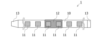
- FIG. 1 is a diagram showing an electrocardiograph according to an embodiment worn on the upper arm.
- FIG. 2 is a plan view of the electrocardiograph according to the embodiment.
- FIG. 3 is a perspective view of the electrocardiograph according to the embodiment.
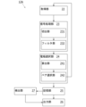
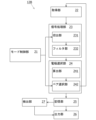
- FIG. 4 is a block diagram showing an example of the functional configuration of the control main body.
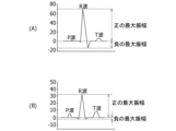
- 5A and 5B are diagrams illustrating examples of electrocardiogram waveforms acquired by the acquisition unit.
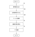
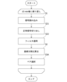
- FIG. 6 is a diagram illustrating an example of a processing flow of a selection process of an electrode pair by the electrode selection unit in the embodiment.
- FIG. 7 is a block diagram showing an example of a functional configuration of a control main body according to the first modified example.
- FIG. 1 is a diagram showing an electrocardiograph according to an embodiment worn on the upper arm.
- FIG. 2 is a plan view of the electrocardiograph according to the embodiment.
- FIG. 3 is a perspective view of the electrocardiograph according to the embodiment.
- FIG. 4 is a block diagram showing an
- FIG. 8 is a diagram showing an example of a processing flow of a selection process of an electrode pair by the electrode selection unit in the first modified example.
- FIG. 9 is a block diagram showing an example of a functional configuration of a control main body according to the second modified example.
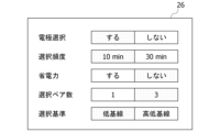
- FIG. 10 is a diagram showing an example of an operation mode designation screen that the mode control unit outputs to the output unit in the second modified example.
- FIG. 11 is a diagram showing a first example of a processing flow of a selection process of an electrode pair by the electrode selection unit in the second modified example.
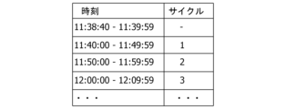
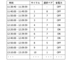
- FIG. 12 is a diagram illustrating the correspondence between the cycle executed every 10 minutes and the time.
- FIG. 13 is a diagram showing a second example of the processing flow of the selection process of an electrode pair by the electrode selection unit in the second modified example.
- FIG. 14 is a diagram showing an example of a process flow of electrocardiogram measurement when a power saving operation is started in the second modified example.
- FIG. 15 is a diagram illustrating an example of switching the power
- An electrocardiograph 1 according to this application example is a wearable electrocardiograph that is fixed by wrapping a band 10 around a measurement site of a subject as shown in Fig. 1.
- a plurality of electrodes 11 and a control body 12 are fixed to the band 10.
- measurement sites to which the band 10 is attached include upper limbs (upper arms, forearms, wrists, hands, fingers), lower limbs (thighs, lower legs, ankles, feet, fingers), head, neck, chest, abdomen, earlobes, etc., and are appropriately selected according to a measurement algorithm, etc.
- the electrocardiogram signal used to detect the characteristics of the electrocardiogram waveform is acquired, for example, using two electrodes 11 (one electrode pair). Three or more electrodes 11 are arranged side by side on the band 10, and the pair of electrodes 11 to be used for electrocardiogram measurement is selected by the pair selection unit 242 (see FIG. 4).
- the pair selection unit 242 selects a pair of electrodes 11, for example, the potential difference is obtained for all pairs of electrodes 11 selected from the multiple electrodes 11, and is acquired as an electrocardiogram signal.
- the pair selection unit 242 calculates a feature based on the absolute value of the maximum amplitude in the positive direction and the absolute value of the maximum amplitude in the negative direction when the baseline potential in the electrocardiogram waveform indicating the time series change of the electrocardiogram signal is used as a reference, and selects a pair of electrodes 11 to be used for detecting the characteristics of the electrocardiogram waveform based on the calculated feature.
- detecting the characteristics of the electrocardiogram waveform is also referred to as electrocardiogram measurement.
- a pair of electrodes suitable for detecting the characteristics of the electrocardiogram waveform can be selected from multiple pairs of electrodes.
- Fig. 1 is a diagram showing an electrocardiograph 1 according to an embodiment worn on the upper arm.
- Fig. 2 is a plan view of the electrocardiograph 1 according to an embodiment.
- Fig. 3 is a perspective view of the electrocardiograph 1 according to an embodiment.
- the electrocardiograph 1 is not limited to a device that performs only electrocardiographic measurement, and may be a biosignal measuring device that measures biosignals other than electrocardiogram signals, such as blood pressure and blood oxygen concentration.
- the electrocardiograph 1 of this embodiment is an upper arm electrocardiogram device that is worn on the user's upper arm (preferably the left upper arm close to the heart) and is used to measure an electrocardiogram signal as a biosignal.
- the electrocardiograph 1 mainly comprises a band 10, a number of electrodes 11 fixed to the band 10, and a control unit 12 fixed to the band 10.
- the band 10 is a member (fixing member) for fixing the electrodes 11 in a state where they are pressed against the living body.
- a strip-shaped band 10 made of a flexible and malleable material (e.g., chemical fiber, silicone, leather, etc.) is used.
- a fixing mechanism 13 is provided at the longitudinal end of the band 10. As shown in Figures 1 and 3, the band 10 is made into a loop and fastened with the fixing mechanism 13, allowing the electrocardiograph 1 to be worn on the upper arm.
- the fixing mechanism 13 may be any type of fastener, hook, connector, button, magnet, etc.
- Electrodes 11 also called an electrode array
- the multiple electrodes 11 are embedded and fixed in the band 10 with the surface that comes into contact with the living body exposed on the inside (living body side) of the band 10.
- the multiple electrodes 11 are arranged in a row at equal intervals in the longitudinal direction of the band 10. This allows the electrodes 11 to come into contact with different positions around the arm when the band 10 is wrapped around the arm.
- the number of electrodes 11 can be designed as desired.
- at least two electrodes 11 one electrode pair
- three or more electrodes 11 may be provided to increase the reliability and robustness of the measurement. In this embodiment, a configuration with six electrodes 11 is adopted.
- the electrodes 11 are dry metal electrodes. Wet electrodes (gel electrodes, etc.) have problems such as the risk of skin rashes and itching when worn for long periods of time, and low durability and ease of maintenance, whereas the dry electrodes 11 do not have such problems.
- the electrocardiograph 1 of this embodiment is designed to be worn for long periods of time and to monitor electrocardiogram signals for 24 hours, so dry electrodes 11 are preferable.
- the control body 12 is a processing unit that controls the electrocardiograph 1 and processes signals.
- the control body 12 has a structure in which a processor, memory, battery, and other circuits are mounted inside a case made of, for example, resin or metal.
- the control body 12 may also be provided with a physical switch and a display. Although not shown, the control body 12 and the multiple electrodes 11 are connected via signal lines.
- Control unit 4 is a block diagram showing an example of the functional configuration of the control body 12.
- the control body 12 includes an acquisition unit 22, an electrode selection unit 24, a storage unit 25, an output unit 26, and a detection unit 27.
- a processor is arranged in the control body 12, and the processor executes a program stored in the storage unit 25 to realize each processing unit such as the acquisition unit 22, the electrode selection unit 24, the output unit 26, and the detection unit 27.
- the control body 12 can be regarded as a computer.
- each processing unit such as the acquisition unit 22, the electrode selection unit 24, the output unit 26, and the detection unit 27 may be realized by a dedicated hardware circuit.
- the acquisition unit 22 is a circuit that uses a differential amplifier to amplify the potential difference between electrode pairs selected from the multiple electrodes 11 provided in the electrocardiograph 1, and outputs it as an electrocardiogram signal. For example, when the electrode selection unit 24 selects pairs of electrodes 11, the acquisition unit 22 acquires the potential differences for all pairs of electrodes 11 selected from the multiple electrodes 11, and outputs it as an electrocardiogram signal.
- the electrocardiogram signal is a signal that indicates the electrical activity of the heart. In this embodiment, electrode pairs are selected from the six electrodes 11 provided in the electrocardiograph 1, so the total number of electrode pairs is 15 pairs.
- the acquisition unit 22 acquires the potential differences of the selected pairs of electrodes 11, and outputs it as an electrocardiogram signal.
- the electrode selection unit 24 selects a pair of electrodes 11 to be used for electrocardiogram measurement.
- the electrode selection unit 24 selects, for example, a pair of electrodes 11 from which an electrocardiogram signal suitable for detecting atrial fibrillation can be acquired. Atrial fibrillation is detected, for example, when the R-R Interval (RRI), which is the interval between the peaks of R waves, is irregular and no P waves are present in the electrocardiogram waveform.
- the electrode selection unit 24 has a calculation unit 241 and a pair selection unit 242.
- the calculation unit 241 calculates a feature value related to the position of a baseline in the electrocardiogram waveform that shows the time series change of the input electrocardiogram signal.
- the baseline is a straight line that connects the start point of a P wave and the start point of the next P wave in the electrocardiogram waveform.
- the position of the baseline in the electrocardiogram waveform is, for example, a straight line that shows a state in which no part of the heart is excited in the electrocardiogram waveform.
- the position of the baseline may be, for example, a straight line connecting the start point of a P wave and the start point of the next P wave when the electrocardiogram waveform is adjusted so that the difference between the maximum amplitude and the minimum amplitude of each waveform included in the electrocardiogram waveform is constant.
- the feature amount related to the position of the baseline may be, for example, the position of a straight line indicating a state in which no part of the heart is excited in the electrocardiogram waveform.
- the feature amount related to the position of the baseline may also be the ratio of maximum amplitudes (baseline division ratio).
- the baseline division ratio is calculated, for example, by "(absolute value of the maximum positive amplitude)/(absolute value of the maximum negative amplitude)".
- the baseline division ratio may also be calculated by "(the greater value of the absolute value of the maximum positive amplitude and the absolute value of the maximum negative amplitude)/(the smaller value of the absolute value of the maximum positive amplitude and the absolute value of the maximum negative amplitude)".
- the calculation unit 241 calculates the baseline division ratio for all pairs of the electrodes 11. In the following description, a case in which the baseline division ratio is used as the feature amount related to the position of the baseline will be described as an example.
- FIG. 5A and 5B are diagrams illustrating electrocardiogram waveforms acquired by the acquisition unit 22.
- the vertical axis of FIG. 5A and FIG. 5B illustrates potential difference (mV), and the horizontal axis illustrates time (seconds).
- the electrocardiogram waveform acquired by the acquisition unit 22 has a different waveform depending on the electrode pair used for measurement.
- FIG. 5A and FIG. 5B are electrocardiogram waveforms measured by the acquisition unit 22 using different electrode pairs.
- the amplitude of the R wave which indicates the maximum amplitude of the electrocardiogram waveform, is larger in FIG. 5A than in FIG. 5B, while the amplitude of the P wave, which is used for detecting atrial fibrillation, etc., is larger in FIG. 5B than in FIG. 5A.
- the waveform in FIG. 5B is more preferable than the waveform in FIG. 5A.
- the waveform in FIG. 5B has a larger value than the waveform in FIG. 5A.
- the baseline division ratio is an index that increases the further the baseline is below the QRS wave.
- the pair selection unit 242 selects a pair of electrodes 11 to be used for electrocardiogram measurement based on the baseline division ratio calculated by the calculation unit 241. For example, the pair selection unit 242 selects the pair of electrodes 11 with the largest calculated baseline division ratio as the pair of electrodes 11 to be used for electrocardiogram measurement.
- the pair selection unit 242 stores information indicating the selected pair of electrodes 11 in the storage unit 25.
- the pair selection unit 242 also stores the electrocardiogram signal acquired by the selected pair of electrodes 11 in the storage unit 25.
- the storage unit 25 is a non-volatile memory.
- the output unit 26 is, for example, a Liquid Crystal Display (LCD), a Plasma Display Panel (PDP), an inorganic electroluminescence (EL) panel, or an organic EL panel.
- the output unit 26 displays, for example, information indicating the pair of electrodes 11 selected by the pair selection unit 242 and an electrocardiogram waveform indicating the time series change of the electrocardiogram signal acquired by the acquisition unit 22.
- the output unit 26 may be provided with, for example, a touch panel superimposed thereon for detecting a touch operation by the user's finger or the like. By providing a touch panel superimposed on the output unit 26, the electrocardiograph 1 can provide the user with an intuitive operating environment.
- the detection unit 27 detects features of the electrocardiogram signal stored in the storage unit 25, and detects atrial fibrillation based on the detected features.
- the detection unit 27 outputs the atrial fibrillation detection result to the output unit 26.
- FIG. 6 is a diagram showing an example of a processing flow of the selection process of a pair of electrodes 11 by the electrode selection unit 24 in the embodiment.
- the electrode selection unit 24 selects one pair of electrodes 11.
- an example of the processing flow of the selection process of a pair of electrodes 11 by the electrode selection unit 24 in the embodiment will be described with reference to Fig. 6.
- step S1 the electrode selection unit 24 acquires the electrocardiogram signal acquired by the acquisition unit 22.
- step S2 the calculation unit 241 calculates the baseline division ratio.
- step S3 the pair selection unit 242 selects a pair of electrodes 11 to be used for electrocardiogram measurement based on the baseline division ratio calculated in step S2.
- the pair selection unit 242 stores information indicating the selected pair of electrodes 11 in the storage unit 25. Thereafter, the electrocardiogram signal acquired by the selected electrodes 11 is stored in the storage unit 25, and the detection unit 27 detects atrial fibrillation using the electrocardiogram signal stored in the storage unit 25.
- a pair of electrodes 11 is selected based on the maximum amplitude of the waveform of the electrocardiogram signal, there is a risk of selecting a pair of electrodes 11 that acquires an electrocardiogram signal with a large maximum amplitude (amplitude of the R wave) but a small amplitude of the P wave, as in the waveform of FIG. 5A.
- a pair of electrodes 11 that can acquire an electrocardiogram signal in which the P wave appears more clearly can be selected as the pair of electrodes 11 to be used for electrocardiogram measurement.
- FIG. 7 is a block diagram showing an example of the functional configuration of a control body 12A according to a first modified example.
- the control body 12A differs from the control body 12 according to the embodiment in that it further includes a signal processing unit 23.
- the signal processing unit 23 performs AD conversion and filtering of the electrocardiogram signal acquired by the acquisition unit 22.
- the signal processing unit 23 outputs the electrocardiogram signal that has been AD converted and filtered to the electrode selection unit 24.
- the signal processing unit 23 has an extraction unit 231 and a filter unit 232.
- the extraction unit 231 extracts a normally acquired electrocardiogram signal from the electrocardiogram signal output by the acquisition unit 22. Examples of normally acquired electrocardiogram signals include signals that are not saturated and signals that do not have consecutive "0s".
- the length of the electrocardiogram signal to be extracted is, for example, 10 seconds.
- the filter unit 232 removes high-frequency noise and low-frequency noise from the electrocardiogram signal extracted by the extraction unit 231 to increase the signal-to-noise ratio.
- High-frequency noise can be caused by, for example, myoelectric potential or power supply noise present around the subject.
- Low-frequency noise can be caused by, for example, the position of the electrodes 11 shifting due to the subject's movements.
- the filter unit 232 is, for example, a band-pass filter.
- the signal processing unit 23 outputs the electrocardiogram signal processed by the extraction unit 231 and the filter unit 232 to the electrode selection unit 24.
- FIG. 8 is a diagram showing an example of a processing flow of the selection process of a pair of electrodes 11 by the electrode selection unit 24 in the first modified example. Below, an example of a processing flow of the selection process of a pair of electrodes 11 by the electrode selection unit 24 in the first modified example will be described with reference to FIG. 8.
- step S21 the extraction unit 231 extracts a normal signal from the electrocardiogram signal read in step S1.
- step S22 the filter unit 232 removes high-frequency noise and low-frequency noise from the signal extracted in step S21 to increase the signal-to-noise ratio.
- noise is removed by the process of the signal processing unit 23 in step S22, so that even if the subject wearing the electrocardiograph 1 is moving freely, the baseline division ratio can be calculated with high accuracy, and thus the pair selection of the electrodes 11 can be performed with high accuracy.
- FIG. 9 is a block diagram showing an example of the functional configuration of the control body 12B according to the second modified example.
- the control body 12B differs from the control body 12A according to the first modified example in that it further includes a mode control unit 21.
- the mode control unit 21 accepts from the user a specification of an operation mode related to electrocardiogram measurement.
- the operation mode includes, for example, specification of whether or not to select a pair of electrodes 11 to be used for electrocardiogram measurement, the frequency of selecting a pair of electrodes 11, whether or not to save power, the number of pairs of electrodes 11 to be selected, and the criteria for selecting pairs of electrodes 11.
- the mode control unit 21 may, for example, output an operation mode designation screen to the output unit 26 and accept the designation of the operation mode from the user.
- FIG. 10 is a diagram showing an example of an operation mode designation screen that the mode control unit 21 outputs to the output unit 26 in the second modified example.
- the operation mode designation screen illustrated in FIG. 10 displays the items "electrode selection,” “selection frequency,” “power saving,” “number of selected pairs,” and “selection criteria.”
- the selected parameter is indicated by coloring the background of the selected value.
- Electrode Selection whether or not to select electrodes 11 is specified.
- a pair of electrodes 11 to be used for electrocardiogram measurement is selected by the process illustrated in FIG. 11 described later.
- No is specified in the "Electrode Selection” item, for example, a default pair of electrodes 11 is used for electrocardiogram measurement.
- Information indicating the default pair of electrodes 11 is stored in the memory unit 25, for example, when the electrocardiograph 1 is manufactured.
- the "selection frequency” field specifies how often the selection of a pair of electrodes 11 is performed. When “10 min” is specified in the “selection frequency” field, the selection of a pair of electrodes 11 is performed once every 10 minutes. When “30 min” is specified in the “selection frequency” field, the selection of a pair of electrodes 11 is performed once every 30 minutes. The period from one selection of an electrode 11 to the next is also referred to as "one cycle.”
- the presence or absence of power saving mode is specified.
- the power saving mode is executed.
- the power saving mode for example, when the same pair of electrodes 11 is selected for two consecutive cycles, a power saving operation is initiated in which the supply of power to electrodes other than the pair of electrodes 11 is turned off for four cycles.
- the supply of power to all electrodes 11 is resumed, and a new pair of electrodes 11 to be used for electrocardiogram measurement is selected by the pair selection unit 242.
- the power saving mode is not executed.
- the "Number of selected pairs” field specifies the number of pairs of electrodes 11 to be used for electrocardiogram measurement.
- the pair selection unit 242 selects one pair of electrodes 11 to be used for electrocardiogram measurement.
- the pair selection unit 242 selects three pairs of electrodes 11 to be used for electrocardiogram measurement.
- a criterion for selecting a pair of electrodes 11 is specified.
- low baseline is selected in the “selection criteria” item
- a pair of electrodes 11 with a low baseline (large baseline division ratio) in the waveform of the electrocardiogram signal is preferentially selected as a pair of electrodes 11 to be used for electrocardiogram measurement.
- high-low baseline is selected in the “selection criteria” item
- a pair of electrodes 11 with a low baseline (large baseline division ratio) in the waveform of the electrocardiogram signal and a pair of electrodes 11 with a high baseline (small baseline division ratio) are selected as a pair of electrodes 11 to be used for electrocardiogram measurement.
- a total of two pairs of electrodes 11 may be selected by the pair selection unit 242, one pair of electrodes 11 with the largest baseline division ratio and one pair of electrodes 11 with the smallest baseline division ratio.
- FIG. 11 is a diagram showing a first example of the processing flow of the selection process of a pair of electrodes 11 by the electrode selection unit 24 in the second modified example.
- the operation mode illustrated in FIG. 10 has been specified. That is, it is assumed that the operation modes specified are "Yes” for "Electrode Selection”, “10 min” for “Selection Frequency”, “No” for "Power Saving”, “3” for "Number of Selected Pairs", and “Low Baseline” for "Selection Criteria”.
- step S3A the pair selection unit 242 selects pairs of electrodes 11 to be used for electrocardiogram measurement, the number of pairs being the "number of selected pairs" accepted by the mode control unit 21.
- the three pairs of electrodes 11 to be used for electrocardiogram measurement are selected in ascending order of the baseline position, i.e., the largest baseline division ratio.
- FIG. 12 is a diagram illustrating the correspondence between the cycle executed every 10 minutes and the time.
- the items "time” and "cycle” are illustrated.
- the control body 12 starts measurement at 11:38:40. In this case, the control body 12 waits without starting measurement until 11:39:59. Then, at 11:40:00, the processes of steps S1, S21, S22, S2, and S3 are executed to select a pair of electrodes 11 to be used for electrocardiogram measurement, and electrocardiogram measurement is performed using the selected pair of electrodes 11.
- steps S1, S21, S22, S2, and S3 are executed to reselect a pair of electrodes 11 to be used for electrocardiogram measurement, and electrocardiogram measurement is performed using the reselected pair of electrodes 11.
- steps S1, S21, S22, S2, and S3 are executed to reselect a pair of electrodes 11 to be used for electrocardiogram measurement, and electrocardiogram measurement is performed using the reselected pair of electrodes 11.
- 11:50 the processes of steps S1, S21, S22, S2, and S3 are executed to reselect a pair of electrodes 11 to be used for electrocardiogram measurement, and electrocardiogram measurement is performed using the reselected pair of electrodes 11. The same applies after 11:50.
- FIG. 13 is a diagram showing a second example of the process flow of the selection process of a pair of electrodes 11 by the electrode selection unit 24 in the second modified example.
- “Yes” is specified for "Electrode selection”, "10 min” for “Selection frequency”, “Yes” for “Power saving”, “1” for “Number of selected pairs”, and “Low baseline” for “Selection criteria” as the operation mode.
- step S31 the mode control unit 21 determines whether or not the same pair of electrodes 11 has been selected by the pair selection unit 242 in consecutive cycles. If the same pair of electrodes 11 has been selected in consecutive cycles (YES in step S31), the process proceeds to step S32. If the same pair of electrodes 11 has not been selected in consecutive cycles (NO in step S32), the process ends.
- step S32 the mode control unit 21 starts a power saving operation.
- the power saving operation starts, the supply of power to the electrodes 11 other than the pair of electrodes 11 selected in step S31 is stopped.
- FIG. 14 is a diagram showing an example of the process flow for electrocardiogram measurement when power-saving operation is started in the second modified example. Below, an example of the process flow for electrocardiogram measurement when power-saving operation is started in the second modified example is described with reference to FIG. 14.
- step S41 the acquisition unit 22 acquires an electrocardiogram signal using the pair of electrodes 11 stored in the memory unit 25.
- step S42 the electrocardiogram signal filtered by the filter unit 232 in step S22 is stored in the memory unit 25.
- the detection unit 27 detects, for example, the presence or absence of atrial fibrillation using the electrocardiogram signal stored in the memory unit 25.
- step S43 power supply to all of the electrodes 11 is resumed.
- FIG. 15 is a diagram illustrating an example of switching the power saving operation on and off.
- FIG. 15 as in FIG. 12, it is assumed that electrocardiogram measurement started at 11:38:40.
- the items "Time”, “Cycle”, “Selected Pair”, and “Power Saving” are illustrated.
- “Time” and “Cycle” are the same as in FIG. 12, and therefore their explanation will be omitted.
- "Selected Pair” illustrates information indicating the pair of electrodes 11 selected by the pair selection unit 242.
- a unique ID is assigned to each pair of electrodes 11, and “Selected Pair” illustrates an ID indicating the pair of electrodes 11.
- “Power Saving” illustrates whether or not the power saving operation is being performed.
- “ON” illustrates an example of the power saving operation being performed
- “OFF” illustrates an example of the power saving operation not being performed.
- the same pair of electrodes 11 is selected consecutively from the second cycle to the third cycle. Therefore, power saving operation is performed for four cycles from the fourth cycle to the seventh cycle, and power supply is stopped to the electrodes 11 other than the pair of electrodes 11 indicated by ID "7". In the eighth cycle, power supply to all electrodes 11 is resumed, and the pair selection unit 242 selects a pair of electrodes 11.
- the mode control unit 21 accepts the operation mode designation, so that electrocardiogram measurement can be performed in an operation mode according to the subject's preference.
- the power saving mode when the power saving mode is turned on, the power supply to the electrodes 11 other than the pair of electrodes 11 selected in successive cycles is stopped, so that the power consumption of the electrocardiograph 1 can be reduced.
- the power saving mode if the same pair of electrodes 11 is selected for two consecutive cycles, power saving operation is initiated and power supply to the electrodes 11 other than the selected pair of electrodes 11 is stopped. If the same pair of electrodes 11 is selected for two consecutive cycles, there is a high probability that the same pair of electrodes 11 will continue to be selected due to reasons such as the posture of the person being measured being stable. Therefore, even if power saving operation is initiated when the same pair of electrodes 11 is selected for two consecutive cycles, it is considered that the impact on the measurement accuracy of electrocardiogram measurement by the electrocardiograph 1 is low.
- the baseline division ratio is used as the feature quantity related to the position of the baseline, but other values can be used as the feature quantity related to the position of the baseline.
- the feature quantity related to the position of the baseline may be, for example, a value obtained by dividing the greater of the absolute value of the maximum amplitude in the positive direction and the absolute value of the maximum amplitude in the negative direction by the smaller value when the potential of the baseline of the electrocardiogram waveform is used as a reference.
- the feature quantity related to the position of the baseline may be, for example, a difference between the absolute value of the maximum amplitude in the positive direction and the absolute value of the maximum amplitude in the negative direction in the electrocardiogram waveform when the difference between the maximum amplitude and the minimum amplitude of each waveform included in the electrocardiogram waveform is adjusted to be constant.
- the feature quantity related to the position of the baseline may be, for example, the average of the amplitudes of the P wave, R wave, S wave, and Q wave in the electrocardiogram waveform.
- the feature amount includes a value obtained by dividing a larger value of an absolute value of the maximum amplitude in the positive direction and an absolute value of the maximum amplitude in the negative direction in the electrocardiogram waveform by a smaller value of the absolute value of the maximum amplitude in the positive direction and an absolute value of the maximum amplitude in the negative direction in the electrocardiogram waveform.
- the characteristic includes at least one of an RRI, which is an interval between peaks of an R wave in the electrocardiogram waveform, and the presence or absence of a P wave in the electrocardiogram waveform.
- the selection unit (242) selects the set of measurement electrodes at predetermined intervals,
- the device further includes a control unit (21) that, when the same set of electrodes (11) is consecutively selected as the set of measurement electrodes, stops the supply of power to the electrodes (11) other than the set of measurement electrodes.
- a biosignal measuring device (1) according to any one of appendices 1 to 6.
- ⁇ Appendix 8> The selection unit (242) Accepting a designation of the number of sets of measurement electrodes to be selected; selecting the set of measurement electrodes as many as the number of sets received; A biosignal measuring device (1) according to any one of appendices 1 to 7.
- ⁇ Appendix 9> The detection unit detects atrial fibrillation based on the detected features.
Landscapes
- Health & Medical Sciences (AREA)
- Life Sciences & Earth Sciences (AREA)
- Cardiology (AREA)
- Heart & Thoracic Surgery (AREA)
- Molecular Biology (AREA)
- Pathology (AREA)
- Engineering & Computer Science (AREA)
- Biomedical Technology (AREA)
- Physics & Mathematics (AREA)
- Medical Informatics (AREA)
- Biophysics (AREA)
- Surgery (AREA)
- Animal Behavior & Ethology (AREA)
- General Health & Medical Sciences (AREA)
- Public Health (AREA)
- Veterinary Medicine (AREA)
- Measurement And Recording Of Electrical Phenomena And Electrical Characteristics Of The Living Body (AREA)
Abstract
複数組の電極の中から心電計測に好適な電極の組を選択できる生体信号計測装置を提供する。本生体信号計測装置は、被計測者に巻きつけられる帯状の固定部材と、上記固定部材に配置される複数組の電極と、上記複数組の電極の夫々によって取得される上記被計測者の心電図波形の基線の電位を基準としたときにおける正の方向の最大振幅の絶対値と負の方向における最大振幅の絶対値とに基づく特徴量に基づいて、上記複数組の電極の中から前記心電図波形の取得に用いる測定電極の組を選択する選択部と、選択された上記測定電極の組を用いて上記心電図波形の特徴を検出する検出部と、を備える。
Description
本発明は、生体信号計測装置に関する。
長期間連続して身体に装着し、心電図波形のモニタリングを行う、ウェアラブルタイプの生体信号計測装置が知られている。例えば、24時間ホルター心電計等の医療用途の装置から、スマートウォッチのようなコンシューマー向け装置まで、様々な製品が存在する。例えば、特許文献1では、上腕に複数の電極を接触させ、取得された心電図波形のR波の振幅に着目し、それが最大となる電極の組を選択して心電波形の計測に用いる心電計測装置が記載されている。
心電図波形のR波の振幅が最大となる電極の組が選択されても、選択された電極の組では心電解析に用いられる波形情報が計測されていない可能性もある。例えば、心房細動の検出にはP波が消失して確認できないことやR波の周期が一定ではないことが用いられるが、信号の振幅が最大となる電極の組によって取得される信号において、P波がそもそも計測されていない虞もある。そのため、選択した電極の組では正しく心電解析できない虞がある。
開示の技術の1つの側面は、複数組の電極の中から心電計測に好適な電極の組を選択できる生体信号計測装置を提供することを目的とする。
開示の技術の1つの側面は、次のような生体信号計測装置によって例示される。本生体信号計測装置は、被計測者に巻きつけられる帯状の固定部材と、上記固定部材に配置される複数組の電極と、上記複数組の電極の夫々によって取得される上記被計測者の心電図波形の基線の電位を基準としたときにおける正の方向の最大振幅の絶対値と負の方向における最大振幅の絶対値とに基づく特徴量に基づいて、上記複数組の電極の中から上記心電図波形の取得に用いる測定電極の組を選択する選択部と、選択された上記測定電極の組を用いて上記心電図波形の特徴を検出する検出部と、を備える。
本生体信号計測装置によれば、上記特徴量に基づいて測定電極の組が選択される。本生体信号計測装置は、このような特徴を備えることで、複数組の電極の中から心電図波形の特徴検出に好適な電極の組を選択できる。上記検出部によって検出される上記特徴としては、例えば、上記心電図波形におけるR波のピークの間隔であるRRIであってもよいし、P波の有無であってもよい。また、上記特徴量は、上記心電図波形における上記正の方向の上記最大振幅の上記絶対値及び上記負の方向における上記最大振幅の上記絶対値のうちの大きい方の値を小さい方の値で除算した値であってもよい。また、上記特徴量は、上記心電図波形に含まれる各波形の最大振幅と最小振幅の差が一定となるように上記心電図波形が調整されている場合には、上記心電図波形における上記正の方向の上記最大振幅の上記絶対値と上記負の方向における上記最大振幅の上記絶対値との差であってもよいし、上記心電図波形における上記正の方向の上記最大振幅の第1の絶対値及び上記負の方向における上記最大振幅の第2の絶対値の少なくとも一方であってもよい。また、上記選択部は、他の電極の組よりも上記特徴量が大きい電極の組を上記測定電極の組として選択してもよい。
本生体信号計測装置は、次の特徴をさらに備えてもよい。上記選択部は、所定間隔で上記測定電極の組の選択を実行し、連続して同一の上記電極の組が上記測定電極の組として選択されると、上記測定電極の組以外の上記電極に対する電力の供給を停止する制御部をさらに備える。本生体信号計測装置によれば、測定電極の組以外の電極に対する電力の供給が停止されるため、本生体信号計測装置の消費電力を低減できる。また、連続して同じ電極の組が測定電極の組として選択される場合、引き続き同じ電極の組が測定電極の組として選択される蓋然性が高い。そのため、測定電極の組以外の電極に対する電力の供給を停止しても心電計測の計測精度に対する影響は低いと考えられる。
本生体信号計測装置は、次の特徴をさらに備えてもよい。上記選択部は、選択する上記測定電極の組の数の指定を受け付け、受け付けた数の組だけ上記測定電極の組を選択する。このような特徴を備える生体信号計測装置であれば、被計測者の要望に応じて柔軟に測定電極の組の数を変更できる。
本生体信号計測装置は、次の特徴をさらに備えてもよい。上記検出部は、検出した上記特徴を基に心房細動を検出する。このような特徴を備える生体信号計測装置であれば、上記選択部によって選択された測定電極の組を用いて、心房細動を検出できる。
開示の技術によれば、複数組の電極の中から心電計測に好適な電極の組を選択できる。
<適用例>
本発明の適用例について説明する。本適用例に係る心電計1は、例えば、図1に例示するような被計測者の計測部位にバンド10を巻き付けることで固定されるウェアラブルな心電計である。バンド10には、複数の電極11と制御本体12とが固定される。バンド10を装着する計測部位としては、上肢(上腕、前腕、手首、手、指)、下肢(大腿、下腿、足首、足、指)、頭部、頸部、胸部、腹部、耳朶等を例示でき、計測アルゴリズム等に応じて適宜選択される。
本発明の適用例について説明する。本適用例に係る心電計1は、例えば、図1に例示するような被計測者の計測部位にバンド10を巻き付けることで固定されるウェアラブルな心電計である。バンド10には、複数の電極11と制御本体12とが固定される。バンド10を装着する計測部位としては、上肢(上腕、前腕、手首、手、指)、下肢(大腿、下腿、足首、足、指)、頭部、頸部、胸部、腹部、耳朶等を例示でき、計測アルゴリズム等に応じて適宜選択される。
心電図波形の特徴検出に用いられる心電図信号は、例えば、2つの電極11(1組の電極ペア)を用いて取得される。バンド10には、3以上の電極11が並んで配置されており、心電計測に用いる電極11のペアがペア選択部242(図4参照)によって選択される。
ペア選択部242による電極11のペアの選択では、例えば、複数の電極11から選択される電極11の全てのペアについて電位差を取得し、心電図信号として取得される。ペア選択部242は、心電図信号の時系列変化を示す心電図波形における基線の電位を基準としたときにおける正の方向の最大振幅の絶対値と負の方向における最大振幅の絶対値とに基づく特徴量を算出し、算出した特徴量を基に、心電図波形の特徴検出に用いる電極11のペアを選択する。以下、本明細書において、心電図波形の特徴を検出することを心電計測とも称する。本適用例によれば、上記特徴量を用いることで、複数組の電極の中から心電図波形の特徴検出に好適な電極の組を選択できる。
<実施形態>
以下、図面を参照して実施形態について説明する。図1は、実施形態に係る心電計1を上腕に装着した様子を示す図である。図2は、実施形態に係る心電計1の平面図である。図3は、実施形態に係る心電計1の斜視図である。なお、心電計1は心電計測のみを行う装置に限定されず、血圧や血中酸素濃度等の心電図信号以外の生体信号も計測する生体信号計測装置であってもよい。
以下、図面を参照して実施形態について説明する。図1は、実施形態に係る心電計1を上腕に装着した様子を示す図である。図2は、実施形態に係る心電計1の平面図である。図3は、実施形態に係る心電計1の斜視図である。なお、心電計1は心電計測のみを行う装置に限定されず、血圧や血中酸素濃度等の心電図信号以外の生体信号も計測する生体信号計測装置であってもよい。
本実施形態の心電計1は、ユーザーの上腕(好ましくは心臓に近い左上腕)に装着され、生体信号としての心電図信号を計測するために用いられる上腕心電デバイスである。
心電計1は、主な構成として、バンド10と、バンド10に固定された複数の電極11と、バンド10に固定された制御本体12と、を有する。
バンド10は、電極11を生体に押し当てた状態で固定するための部材(固定部材)である。本実施形態では、可撓性及び柔軟性のある材料(例えば化学繊維、シリコン、皮革等)からなる帯状のバンド10が用いられる。バンド10の長手方向端部には固定機構13が設けられる。図1及び図3に示すようにバンド10をループ状にし、固定機構13で留めることにより、心電計1を上腕に装着できる。固定機構13は、面ファスナ、フック、コネクタ、ボタン、マグネット等どのようなものでもよい。
複数の電極11(電極アレイとも呼ばれる)は、生体との接触面がバンド10の内側(生体側)に露出するようにして、バンド10に埋め込み固定される。複数の電極11は、バンド10の長手方向に一列に等間隔で配置される。これにより、バンド10を腕に巻き付けたときに、腕の周囲の異なる位置に電極11が接触する。電極11の数は任意に設計できる。心電図信号を計測する目的であれば、少なくとも2つの電極11(1組の電極ペア)があればよく、計測の信頼性やロバスト性を高めるために3つ以上の電極11を設けてもよい。本実施形態では、6個の電極11を設ける構成を採用している。
電極11は、乾式の金属電極である。湿式の電極(ゲル電極等)は、長時間装着していると皮膚かぶれや痒みを生じる可能性がある、耐久性やメンテナンス性が低い、等の問題があるのに対し、乾式の電極11はそのような問題がない。本実施形態の心電計1は、長時間装着し続け、心電図信号を24時間モニタリングすることを想定しているため、乾式の電極11であることが好ましい。
制御本体12は、心電計1の制御や信号処理を行う処理ユニットである。制御本体12は、例えば、樹脂や金属からなるケースの内部に、プロセッサ、メモリ、バッテリ、その他の回路が実装された構造を有する。制御本体12には、物理スイッチ及びディスプレイが設けられていてもよい。図示しないが、制御本体12と複数の電極11の間は信号線を介して接続される。
(制御本体)
図4は、制御本体12の機能構成の一例を示すブロック図である。制御本体12は、取得部22、電極選択部24、記憶部25、出力部26及び検出部27を備える。制御本体12には、例えば、プロセッサが配置され、記憶部25に記憶されたプログラムをプロセッサが実行することで、取得部22、電極選択部24、出力部26及び検出部27等の各処理部が実現される。換言すれば、制御本体12は、コンピュータとみなすことができる。なお、取得部22、電極選択部24、出力部26及び検出部27等の各処理部は、専用のハードウェア回路によって実現されてもよい。
図4は、制御本体12の機能構成の一例を示すブロック図である。制御本体12は、取得部22、電極選択部24、記憶部25、出力部26及び検出部27を備える。制御本体12には、例えば、プロセッサが配置され、記憶部25に記憶されたプログラムをプロセッサが実行することで、取得部22、電極選択部24、出力部26及び検出部27等の各処理部が実現される。換言すれば、制御本体12は、コンピュータとみなすことができる。なお、取得部22、電極選択部24、出力部26及び検出部27等の各処理部は、専用のハードウェア回路によって実現されてもよい。
取得部22は、心電計1が備える複数の電極11から選択された電極ペアの間の電位差を差動アンプにより増幅し、心電図信号として出力する回路である。取得部22は、例えば、電極選択部24による電極11のペア選択が実行される際には、複数の電極11から選択される電極11の全てのペアについて電位差を取得し、心電図信号として出力する。心電図信号は、心臓の電気的な活動を示す信号である。本実施形態では、心電計1が有する6個の電極11から電極ペアが選択されるため、電極ペアの総数は15ペアとなる。また、取得部22は、電極選択部24によって心電計測に用いる電極11のペアが選択された後には、選択された電極11のペアの電位差を取得し、心電図信号として出力する。
電極選択部24は、心電計測に用いる電極11のペアを選択する。電極選択部24は、例えば、心房細動の検出に好適な心電図信号を取得できる電極11のペアを選択する。心房細動は、例えば、R波のピークの間隔であるR-R Interval(RRI)が不規則であるとともに、心電図波形においてP波が存在しない場合に検出される。電極選択部24は、算出部241及びペア選択部242を有する。算出部241は、入力された心電図信号の時系列変化を示す心電図波形における基線の位置に係る特徴量を算出する。基線は、心電図波形において、P波の始点と次のP波の始点とを結んだ直線である。心電図波形における基線の位置は、例えば、心電図波形において、心臓のどの部分も興奮していない状態を示す直線である。なお、基線の位置は、例えば、心電図波形に含まれる各波形の最大振幅と最小振幅の差が一定となるように心電図波形が調整したときにおけるP波の始点と次のP波の始点とを結んだ直線であってもよい。基線の位置に係る特徴量としては、例えば、心電図波形において心臓のどの部分も興奮していない状態を示す直線の位置であってもよい。また、基線の位置に係る特徴量としては、最大振幅の比(基線分割比)であってもよい。基線分割比は、例えば、「(正の最大振幅の絶対値)/(負の最大振幅の絶対値)」によって算出される。また、基線分割比は、「(正の最大振幅の絶対値と負の最大振幅の絶対値の大きい方の値)/(正の最大振幅の絶対値と負の最大振幅の絶対値の小さい方の値)」によって算出されてもよい。算出部241は、電極11の全てのペアについて基線分割比を算出する。以降の説明では、基線の位置に係る特徴量として、基線分割比が採用された場合を一例として説明する。
図5A及び図5Bは、取得部22によって取得される心電図波形を例示する図である。図5A及び図5Bの縦軸は電位差(mV)を例示し、横軸は時間(秒)を例示する。取得部22によって取得される心電図波形は、計測に用いる電極ペアによって異なる波形となる。図5A及び図5Bは、夫々異なる電極ペアを用いて取得部22によって計測された心電図波形である。心電図波形の最大振幅を示すR波の振幅は図5Bよりも図5Aの方が大きい一方で、心房細動の検出等に用いられるP波の振幅は図5Aよりも図5Bの方が大きい。すなわち、心房細動の検出を考慮すると、図5Aの波形よりも図5Bの波形の方が好ましい。また、基線分割比をみると、図5Aの波形よりも図5Bの波形の方が大きい値となる。本発明者らが被験者実験により多くの被験者の心電図波形を観察した結果、基線がQRS波の下の方にある心電図波形ほど、P波の振幅が大きい傾向にあるという知見を得た。基線分割比は、基線がQRS波の下の方にあるほど大きくなる指標である。
ペア選択部242は、算出部241によって算出された基線分割比に基づいて、心電計測に用いる電極11のペアを選択する。ペア選択部242は、例えば、算出された基線分割比の最も大きい電極11のペアを心電計測に用いる電極11のペアとして選択する。ペア選択部242は、選択した電極11のペアを示す情報を記憶部25に記憶させる。また、ペア選択部242は、選択した電極11のペアによって取得された心電図信号を記憶部25に記憶させる。記憶部25は、不揮発性のメモリである。
出力部26は、例えば、Liquid Crystal Display(LCD)、Plasma Display Panel(PDP)、無機Electroluminescence(EL)パネル、有機ELパネルである。出力部26は、例えば、ペア選択部242によって選択された電極11のペアを示す情報や取得部22によって取得された心電図信号の時系列変化を示す心電図波形を表示する。出力部26には、例えば、ユーザーの指等によるタッチ操作を検知するタッチパネルが重畳して設けられてもよい。心電計1は、出力部26にタッチパネルが重畳して設けられることで、直感的な操作環境をユーザーに提供することができる。
検出部27は、記憶部25に記憶された心電図信号から当該心電図信号の特徴を検出し、検出した特徴を基に心房細動を検出する。検出部27は、心房細動の検出結果を出力部26に出力させる。
(電極11のペアの選択)
図6は、実施形態における電極選択部24による電極11のペアの選択処理の処理フローの一例を示す図である。図6に例示する例では、電極選択部24は電極11のペアを一組選択する。以下、図6を参照して、実施形態における電極選択部24による電極11のペアの選択処理の処理フローの一例について説明する。
図6は、実施形態における電極選択部24による電極11のペアの選択処理の処理フローの一例を示す図である。図6に例示する例では、電極選択部24は電極11のペアを一組選択する。以下、図6を参照して、実施形態における電極選択部24による電極11のペアの選択処理の処理フローの一例について説明する。
ステップS1では、電極選択部24は、取得部22によって取得された心電図信号を取得する。ステップS2では、算出部241は、基線分割比を算出する。ステップS3では、ペア選択部242は、ステップS2で算出された基線分割比を基に、心電計測に用いる電極11のペアを選択する。ペア選択部242は、選択した電極11のペアを示す情報を記憶部25に記憶させる。以後、選択された電極11によって取得された心電図信号は記憶部25に記憶され、検出部27は記憶部25に記憶された心電図信号を用いて心房細動を検出する。
心電図信号の波形の最大振幅を基に電極11のペアを選択すると、図5Aの波形のように最大振幅(R波の振幅)は大きいもののP波の振幅は小さい心電図信号を取得する電極11のペアを選択する虞がある。本実施形態によれば、基線分割比を用いることで、よりP波が明確に出現する心電図信号を取得できる電極11のペアを心電計測に用いる電極11のペアとして選択できる。
<第1変形例>
実施形態で説明した制御本体12による処理では、取得部22によって取得された心電図信号からノイズ成分を除去する処理が行われない。そのため、心電計1を装着した被計測者が静止せずに動いているような場合では、取得部22によって取得された心電図信号にノイズが含まれるため、基線分割比を高精度に算出することは難しい場合がある。第1変形例では、取得部22によって取得された心電図信号からノイズを除去する処理をさらに実行する変形例について説明する。実施形態と同一の構成については同一の符号を付し、その説明を省略する。以下、図面を参照して第1変形例について説明する。
実施形態で説明した制御本体12による処理では、取得部22によって取得された心電図信号からノイズ成分を除去する処理が行われない。そのため、心電計1を装着した被計測者が静止せずに動いているような場合では、取得部22によって取得された心電図信号にノイズが含まれるため、基線分割比を高精度に算出することは難しい場合がある。第1変形例では、取得部22によって取得された心電図信号からノイズを除去する処理をさらに実行する変形例について説明する。実施形態と同一の構成については同一の符号を付し、その説明を省略する。以下、図面を参照して第1変形例について説明する。
図7は、第1変形例に係る制御本体12Aの機能構成の一例を示すブロック図である。制御本体12Aは、信号処理部23をさらに備える点で実施形態に係る制御本体12とは異なる。
信号処理部23は、取得部22によって取得された心電図信号のAD変換及びフィルタ処理を行う。信号処理部23は、AD変換及びフィルタ処理を行った心電図信号を電極選択部24に対して出力する。信号処理部23は、切出部231及びフィルタ部232を有する。切出部231は、取得部22によって出力された心電図信号から、正常に取得された心電図信号を切り出す。正常に取得された心電図信号としては、例えば、サチレーションしていない信号、「0」が連続していない信号等を挙げることができる。切り出す心電図信号の長さは、例えば、10秒である。
フィルタ部232は、切出部231によって切り出された心電図信号から高周波ノイズ及び低周波ノイズを除去してSN比を高める。高周波ノイズは、例えば、筋電や被計測者の周辺に存在する電源ノイズ等によって生じ得る。また、低周波ノイズは、例えば、被計測者の動き等によって電極11の位置がずれることで生じ得る。フィルタ部232は、例えば、バンドパスフィルタである。信号処理部23は、切出部231及びフィルタ部232による処理が行われた心電図信号を電極選択部24に対して出力する。
図8は、第1変形例における電極選択部24による電極11のペアの選択処理の処理フローの一例を示す図である。以下、図8を参照して、第1変形例における電極選択部24による電極11のペアの選択処理の処理フローの一例について説明する。
ステップS21では、切出部231は、ステップS1で読み込まれた心電図信号から正常な信号を切り出す。ステップS22では、フィルタ部232は、ステップS21で切り出された信号に対して高周波ノイズ及び低周波ノイズを除去してSN比を高める。
図8に例示される処理では、ステップS22における信号処理部23の処理によってノイズが除去されるため、心電計1を装着した被計測者が自由に行動していても、基線分割比を高精度に算出でき、ひいては、電極11のペア選択を高精度に行うことができる。
<第2変形例>
以上説明した実施形態及び第1変形例では、心電計測に用いる電極11のペアの数や電極11のペアの選択頻度等の動作モードの指定を受け付けなかった。第2変形例では、これらの動作モードの指定を受け付ける変形例について説明する。実施形態及び第1変形例と同一の構成については同一の符号を付し、その説明を省略する。以下、図面を参照して第2変形例について説明する。
以上説明した実施形態及び第1変形例では、心電計測に用いる電極11のペアの数や電極11のペアの選択頻度等の動作モードの指定を受け付けなかった。第2変形例では、これらの動作モードの指定を受け付ける変形例について説明する。実施形態及び第1変形例と同一の構成については同一の符号を付し、その説明を省略する。以下、図面を参照して第2変形例について説明する。
図9は、第2変形例に係る制御本体12Bの機能構成の一例を示すブロック図である。制御本体12Bは、モード制御部21をさらに備える点で第1変形例に係る制御本体12Aとは異なる。
モード制御部21は、心電計測に係る動作モードの指定をユーザから受け付ける。動作モードとしては、例えば、心電計測に用いる電極11のペア選択の有無、電極11のペア選択の頻度、省電力の有無、選択する電極11のペアの数、電極11のペアを選択する基準の指定を含む。
モード制御部21は、例えば、出力部26に動作モードの指定画面を出力部26に出力してユーザからの動作モードの指定を受け付けてもよい。図10は、第2変形例においてモード制御部21が出力部26に出力する動作モード指定画面の一例を示す図である。図10に例示する動作モード指定画面では、「電極選択」、「選択頻度」、「省電力」、「選択ペア数」及び「選択基準」の各項目が表示される。図10に例示する動作モード指定画面では、例えば、選択された値の背景に色が付されることで選択されたパラメータが示される。
「電極選択」の項目では、電極11の選択の有無が指定される。「電極選択」の項目において「する」が指定されると、後述する図11に例示される処理によって心電計測に用いる電極11のペアが選択される。「電極選択」の項目において「しない」が指定されると、例えば、既定の電極11のペアが心電計測に用いられる。既定の電極11のペアを示す情報は、例えば、心電計1の製造時において記憶部25に記憶される。
「選択頻度」の項目では、電極11のペアの選択を実行する頻度が指定される。「選択頻度」の項目において「10min」が指定されると、10分に1回の頻度で電極11のペアの選択が実行される。「選択頻度」の項目において「30min」が指定されると、30分に1回の頻度で電極11のペアの選択が実行される。電極11の選択から次の選択までを「1サイクル」とも称する。
「省電力」の項目では、省電力モードの有無が指定される。「省電力」の項目において「する」が指定されると、省電力モードが実行されるようになる。省電力モードでは、例えば、2サイクル連続して同じ電極11のペアが選択されると、当該電極11のペア以外の電極に対する電力の供給が4サイクルに渡ってオフにされる省電力動作が開始される。省電力動作が開始されてから4サイクルが終了すると、全ての電極11に対する電力の供給が再開されて、改めて心電計測に用いる電極11のペアがペア選択部242によって選択される。「省電力」の項目において「しない」が指定されると、省電力モードは実行されない。
「選択ペア数」の項目では、心電計測に用いる電極11のペアの数が指定される。「選択ペア数」の項目において「1」が指定されると、ペア選択部242は、心電計測に用いる電極11のペアを1組選択する。「選択ペア数」の項目において「3」が指定されると、ペア選択部242は、心電計測に用いる電極11のペアを3組選択する。
「選択基準」の項目では、電極11のペアを選択する基準が指定される。「選択基準」の項目において「低基線」が選択されると、心電図信号の波形において基線が低い(基線分割比が大きい)電極11のペアが優先して心電計測に用いる電極11のペアとして選択される。「選択基準」の項目において「高低基線」が選択されると、心電図信号の波形において基線が低い(基線分割比が大きい)電極11のペアと基線が高い(基線分割比が小さい)電極11のペアが心電計測に用いる電極11のペアとして選択される。例えば、「選択ペア数」が「1」で、「選択基準」が「高低基線」の場合、基線分割比が最も大きい電極11のペアが1組、基線分割比が最も小さい電極11のペアが1組、の合計2組の電極11のペアがペア選択部242によって選択されてもよい。
図11は、第2変形例において電極選択部24による電極11のペアの選択処理の処理フローの第1の例を示す図である。図11に例示される処理フローでは、例えば、図10例示した動作モードが指定されたものとする。すなわち、動作モードとして、「電極選択」について「する」、「選択頻度」について「10min」、「省電力」について「しない」、「選択ペア数」について「3」、「選択基準」について「低基線」が指定されたものとする。
ステップS3Aでは、ペア選択部242は、モード制御部21によって受け付けられた「選択ペア数」のペア数だけ心電計測に用いる電極11のペアを選択する。ここでは、心電計測に用いる電極11のペアが、基線の位置の低いもの、すなわち、基線分割比の大きいものから順に3ペア選択される。
そして、「選択頻度」として「10min」が指定されたため、ステップS1、ステップS21、ステップS22、ステップS2及びステップS3Aの各処理が10分毎に繰り返し実行される。
図12は、10分毎に実行されるサイクルと時刻の対応を例示する図である。図12では、「時刻」及び「サイクル」の各項目が例示される。図12では、例えば、11時38分40秒に制御本体12による計測が開始されたものとする。この場合、制御本体12は、11時39分59秒までは計測を開始せずに待機する。そして、11時40分00秒になると、ステップS1、ステップS21、ステップS22、ステップS2及びステップS3の各処理を実行して、心電計測に用いる電極11のペアを選択し、選択した電極11のペアを用いて心電計測を行う。続いて、11時50分00秒になると、ステップS1、ステップS21、ステップS22、ステップS2及びステップS3の各処理を実行して、心電計測に用いる電極11のペアを選択しなおし、選択しなおした電極11のペアを用いて心電計測を行う。11時50分以降も同様である。
続いて、動作モードとして、「省電力」について「する」が選択された場合の処理について説明する。図13は、第2変形例において電極選択部24による電極11のペアの選択処理の処理フローの第2の例を示す図である。第2の例では、動作モードとして、「電極選択」について「する」、「選択頻度」について「10min」、「省電力」について「する」、「選択ペア数」について「1」、「選択基準」について「低基線」が指定されたものとする。
ステップS31では、モード制御部21は、連続したサイクルで同じ電極11のペアがペア選択部242によって選択されたか否かを判定する。連続したサイクルで同じ電極11のペアが選択された場合(ステップS31でYES)、処理はステップS32に進められる。連続したサイクルで同じ電極11のペアが選択されていない場合(ステップS32でNO)、処理は終了される。
ステップS32では、モード制御部21は、省電力動作を開始する。省電力動作が開始されると、ステップS31で選択された電極11のペア以外の電極11に対する電力の供給が停止される。
図14は、第2変形例において省電力動作が開始された場合における心電計測の処理フローの一例を示す図である。以下、図14を参照して、第2変形例において省電力動作が開始された場合における心電計測の処理フローの一例について説明する。
ステップS41では、取得部22は、記憶部25に記憶された電極11のペアを用いて、心電図信号を取得する。ステップS42では、ステップS22でフィルタ部232によってフィルタ処理された心電図信号が記憶部25に記憶される。検出部27は、記憶部25に記憶された心電図信号を用いて、例えば、心房細動の有無を検出する。ステップS41からステップS42までの処理が所定サイクル数(例えば、4サイクル)繰り返されると、処理はステップS43に進められる。ステップS43では、電極11の全てに電力供給が再開される。
図15は、省電力動作のオン、オフの切り替えを例示する図である。図15では、図12と同様に、11時38分40秒に心電計測が開始されたものとする。図15では、「時刻」、「サイクル」、「選択ペア」及び「省電力」の各項目が例示される。「時刻」及び「サイクル」は、図12と同一であるため、その説明を省略する。「選択ペア」は、ペア選択部242によって選択された電極11のペアを示す情報を例示する。図15の例では、電極11のペア夫々にユニークなIDが割り当てられており、「選択ペア」には電極11のペアを示すIDが例示される。「省電力」には、省電力動作が実行されているか否かが例示される。「省電力」において「ON」は省電力動作が実行されていることを例示し、「OFF」は省電力動作が実行されていないことを例示する。
図15を参照すると、第2サイクルから第3サイクルにおいて連続して同一の電極11のペアが選択される。そのため、第4サイクルから第7サイクルまでの4サイクルの間省電力動作が実行され、ID「7」で示される電極11のペア以外の電極11には電力供給が停止される。第8サイクルでは全ての電極11に対する電力供給が再開されて、ペア選択部242による電極11のペアの選択が実行される。
第2変形例によれば、モード制御部21によって動作モードの指定を受け付けるため、被計測者の好みに応じた動作モードで心電計測を行うことができる。また、第2変形例では、省電力モードをオンにした場合、連続したサイクルで選択された電極11のペア以外の電極11に対する電力供給が停止されるため、心電計1の消費電力を抑制できる。
また、省電力モードにおいては、2サイクル連続して同じ電極11のペアが選択された場合に省電力動作が開始されて、選択された電極11のペア以外の電極11への電力供給が停止される。2サイクル連続して同じ電極11のペアが選択される場合、被計測者の姿勢が安定している等の理由で、引き続き同じ電極11のペアが選択される蓋然性が高い。そのため、2サイクル連続して同じ電極11のペアが選択された場合に省電力動作が開始されても、心電計1による心電計測の計測精度に対する影響は低いと考えられる。
<その他の変形>
以上説明した実施形態及び変形例では、基線の位置に係る特徴量として基線分割比が挙げられたが、基線の位置に係る特徴量としては他の値を採用することも可能である。基線の位置に係る特徴量としては、例えば、心電図波形の基線の電位を基準としたときにおける正の方向の最大振幅の絶対値及びを負の方向における最大振幅の絶対値のうちの大きい方の値を小さい方の値で除算した値であってもよい。また、基線の位置に係る特徴量としては、例えば、心電図波形に含まれる各波形の最大振幅と最小振幅の差が一定となるように調整されている場合には、心電図波形における正の方向の最大振幅の絶対値と負の方向における最大振幅の絶対値との差であってもよい。また、基線の位置に係る特徴量としては、例えば、心電図波形におけるP波、R波、S波、Q波の振幅の平均を挙げることができる。
以上説明した実施形態及び変形例では、基線の位置に係る特徴量として基線分割比が挙げられたが、基線の位置に係る特徴量としては他の値を採用することも可能である。基線の位置に係る特徴量としては、例えば、心電図波形の基線の電位を基準としたときにおける正の方向の最大振幅の絶対値及びを負の方向における最大振幅の絶対値のうちの大きい方の値を小さい方の値で除算した値であってもよい。また、基線の位置に係る特徴量としては、例えば、心電図波形に含まれる各波形の最大振幅と最小振幅の差が一定となるように調整されている場合には、心電図波形における正の方向の最大振幅の絶対値と負の方向における最大振幅の絶対値との差であってもよい。また、基線の位置に係る特徴量としては、例えば、心電図波形におけるP波、R波、S波、Q波の振幅の平均を挙げることができる。
以上で開示した実施形態や変形例はそれぞれ組み合わせることができる。
<付記1>
被計測者に巻きつけられる帯状の固定部材(10)と、
前記固定部材に配置される複数組の電極(11)と、
前記複数組の電極の夫々によって取得される前記被計測者の心電図波形の基線の電位を基準としたときにおける正の方向の最大振幅の絶対値と負の方向における最大振幅の絶対値とに基づく特徴量に基づいて、前記複数組の電極の中から前記心電図波形の取得に用いる測定電極の組を選択する選択部(242)と、
選択された前記測定電極の組を用いて前記心電図波形の特徴を検出する検出部(27)と、を備える、
生体信号計測装置(1)。
<付記2>
前記特徴量は、前記心電図波形における前記正の方向の前記最大振幅の絶対値及び前記負の方向における前記最大振幅の絶対値のうちの大きい方の値を小さい方の値で除算した値を含む、
付記1に記載の生体信号計測装置(1)。
<付記3>
前記心電図波形は、前記心電図波形に含まれる各波形の最大振幅と最小振幅の差が一定となるように調整されており、
前記特徴量は、前記心電図波形における前記正の方向の前記最大振幅の前記絶対値と前記負の方向における前記最大振幅の前記絶対値との差を含む、
付記1または2に記載の生体信号計測装置(1)。
<付記4>
前記心電図波形は、前記心電図波形に含まれる各波形の最大振幅と最小振幅の差が一定となるように調整されており、
前記特徴量は、前記心電図波形における前記正の方向の前記最大振幅の第1の絶対値及び前記負の方向における前記最大振幅の第2の絶対値の少なくとも一方を含む、
付記1から3のいずれかひとつに記載の生体信号計測装置(1)。
<付記5>
前記選択部(242)は、他の電極の組よりも前記特徴量が大きい電極の組を前記測定電極の組として選択する、
請求項1から4のいずれかひとつに記載の生体信号計測装置(1)。
<付記6>
前記特徴は、前記心電図波形におけるR波のピークの間隔であるRRI及び前記心電図波形におけるP波の有無の少なくとも一方を含む、
付記1から5のいずれかひとつに記載の生体信号計測装置(1)。
<付記7>
前記選択部(242)は、所定間隔で前記測定電極の組の選択を実行し、
連続して同一の前記電極(11)の組が前記測定電極の組として選択されると、前記測定電極の組以外の前記電極(11)に対する電力の供給を停止する制御部(21)をさらに備える、
付記1から6のいずれかひとつに記載の生体信号計測装置(1)。
<付記8>
前記選択部(242)は、
選択する前記測定電極の組の数の指定を受け付け、
受け付けた数の組だけ前記測定電極の組を選択する、
付記1から7のいずれかひとつに記載の生体信号計測装置(1)。
<付記9>
前記検出部は、検出した前記特徴を基に心房細動を検出する、
付記1から8のいずれかひとつに記載の生体信号計測装置(1)。
1・・心電計
10・・バンド
11・・電極
12・・制御本体
12A・・制御本体
12B・・制御本体
13・・固定機構
21・・モード制御部
22・・取得部
23・・信号処理部
24・・電極選択部
25・・記憶部
26・・出力部
27・・検出部
231・・切出部
232・・フィルタ部
241・・算出部
242・・ペア選択部
10・・バンド
11・・電極
12・・制御本体
12A・・制御本体
12B・・制御本体
13・・固定機構
21・・モード制御部
22・・取得部
23・・信号処理部
24・・電極選択部
25・・記憶部
26・・出力部
27・・検出部
231・・切出部
232・・フィルタ部
241・・算出部
242・・ペア選択部
Claims (9)
- 被計測者に巻きつけられる帯状の固定部材と、
前記固定部材に配置される複数組の電極と、
前記複数組の電極の夫々によって取得される前記被計測者の心電図波形の基線の電位を基準としたときにおける正の方向の最大振幅の絶対値と負の方向における最大振幅の絶対値とに基づく特徴量に基づいて、前記複数組の電極の中から前記心電図波形の取得に用いる測定電極の組を選択する選択部と、
選択された前記測定電極の組を用いて前記心電図波形の特徴を検出する検出部と、を備える、
生体信号計測装置。 - 前記特徴量は、前記心電図波形における前記正の方向の前記最大振幅の前記絶対値及び前記負の方向における前記最大振幅の前記絶対値のうちの大きい方の値を小さい方の値で除算した値を含む、
請求項1に記載の生体信号計測装置。 - 前記心電図波形は、前記心電図波形に含まれる各波形の最大振幅と最小振幅の差が一定となるように調整されており、
前記特徴量は、前記心電図波形における前記正の方向の前記最大振幅の前記絶対値と前記負の方向における前記最大振幅の前記絶対値との差を含む、
請求項1に記載の生体信号計測装置。 - 前記心電図波形は、前記心電図波形に含まれる各波形の最大振幅と最小振幅の差が一定となるように調整されており、
前記特徴量は、前記心電図波形における前記正の方向の前記最大振幅の第1の絶対値及び前記負の方向における前記最大振幅の第2の絶対値の少なくとも一方を含む、
請求項1に記載の生体信号計測装置。 - 前記選択部は、他の電極の組よりも前記特徴量が大きい電極の組を前記測定電極の組として選択する、
請求項1に記載の生体信号計測装置。 - 前記特徴は、前記心電図波形におけるR波のピークの間隔であるRRI及び前記心電図波形におけるP波の有無の少なくとも一方を含む、
請求項1に記載の生体信号計測装置。 - 前記選択部は、所定間隔で前記測定電極の組の選択を実行し、
連続して同一の前記電極の組が前記測定電極の組として選択されると、前記測定電極の組以外の前記電極に対する電力の供給を停止する制御部をさらに備える、
請求項1に記載の生体信号計測装置。 - 前記選択部は、
選択する前記測定電極の組の数の指定を受け付け、
受け付けた数の組だけ前記測定電極の組を選択する、
請求項1に記載の生体信号計測装置。 - 前記検出部は、検出した前記特徴を基に心房細動を検出する、
請求項1から8のいずれか一項に記載の生体信号計測装置。
Applications Claiming Priority (2)
| Application Number | Priority Date | Filing Date | Title |
|---|---|---|---|
| JP2023-130330 | 2023-08-09 | ||
| JP2023130330A JP2025025512A (ja) | 2023-08-09 | 2023-08-09 | 生体信号計測装置 |
Publications (1)
| Publication Number | Publication Date |
|---|---|
| WO2025033439A1 true WO2025033439A1 (ja) | 2025-02-13 |
Family
ID=94533947
Family Applications (1)
| Application Number | Title | Priority Date | Filing Date |
|---|---|---|---|
| PCT/JP2024/028127 Ceased WO2025033439A1 (ja) | 2023-08-09 | 2024-08-06 | 生体信号計測装置 |
Country Status (2)
| Country | Link |
|---|---|
| JP (1) | JP2025025512A (ja) |
| WO (1) | WO2025033439A1 (ja) |
Citations (5)
| Publication number | Priority date | Publication date | Assignee | Title |
|---|---|---|---|---|
| JP2004016248A (ja) * | 2002-06-12 | 2004-01-22 | Junichiro Hayano | 心電図に基づく発作性心房細動の検出・評価システム |
| JP2011147582A (ja) * | 2010-01-21 | 2011-08-04 | Seiko Epson Corp | 心電計測装置 |
| JP2011172963A (ja) * | 2004-03-24 | 2011-09-08 | Nippon Koden Corp | 電極を有する生体情報計測用衣服、生体情報計測システムおよび生体情報計測装置、および装置制御方法 |
| CN102805620A (zh) * | 2012-08-16 | 2012-12-05 | 深圳市邦健电子有限公司 | 一种房颤检测方法和装置 |
| JP2020074846A (ja) * | 2018-11-06 | 2020-05-21 | 株式会社東海理化電機製作所 | 車両用心電検出装置 |
-
2023
- 2023-08-09 JP JP2023130330A patent/JP2025025512A/ja active Pending
-
2024
- 2024-08-06 WO PCT/JP2024/028127 patent/WO2025033439A1/ja not_active Ceased
Patent Citations (5)
| Publication number | Priority date | Publication date | Assignee | Title |
|---|---|---|---|---|
| JP2004016248A (ja) * | 2002-06-12 | 2004-01-22 | Junichiro Hayano | 心電図に基づく発作性心房細動の検出・評価システム |
| JP2011172963A (ja) * | 2004-03-24 | 2011-09-08 | Nippon Koden Corp | 電極を有する生体情報計測用衣服、生体情報計測システムおよび生体情報計測装置、および装置制御方法 |
| JP2011147582A (ja) * | 2010-01-21 | 2011-08-04 | Seiko Epson Corp | 心電計測装置 |
| CN102805620A (zh) * | 2012-08-16 | 2012-12-05 | 深圳市邦健电子有限公司 | 一种房颤检测方法和装置 |
| JP2020074846A (ja) * | 2018-11-06 | 2020-05-21 | 株式会社東海理化電機製作所 | 車両用心電検出装置 |
Also Published As
| Publication number | Publication date |
|---|---|
| JP2025025512A (ja) | 2025-02-21 |
Similar Documents
| Publication | Publication Date | Title |
|---|---|---|
| JP7277970B2 (ja) | ウエアラブルデバイスを利用する心電図測定方法及びシステム | |
| JP6097834B2 (ja) | 携帯型心臓健康モニタリング | |
| Sufi et al. | ECG RR peak detection on mobile phones | |
| US10292600B2 (en) | Biosignal measurement apparatus and biosignal measurement method | |
| US20200060562A1 (en) | Method and device for detecting heart rhythm irregularities | |
| JP6767503B2 (ja) | 接触状態推定装置、生体信号測定装置、接触状態推定方法、接触状態推定プログラム、及び媒体 | |
| JPWO2017179703A1 (ja) | 生体情報分析装置、システム、及び、プログラム | |
| KR20190016891A (ko) | 모션 센서를 이용한 연속 심박수 및 심장박동 이벤트 감지를 위한 시스템 및 방법 | |
| CN105243273A (zh) | 心输出量相关波形的参数检测 | |
| KR101012810B1 (ko) | 단채널 휴대용 무선 심전도 측정장치 및 방법 | |
| Paradiso et al. | Knitted bioclothes for cardiopulmonary monitoring | |
| Taji et al. | An ECG monitoring system using conductive fabric | |
| Phan et al. | Noninvasive, wearable multi biosensors for continuous, long-term monitoring of blood pressure via internet of things applications | |
| Pflugradt et al. | Multi-modal signal acquisition using a synchronized wireless body sensor network in geriatric patients | |
| KR101990383B1 (ko) | 심전도가 측정가능한 혈압 측정 장치 | |
| JP2025025512A (ja) | 生体信号計測装置 | |
| CN113080983A (zh) | 利用低功耗长距离通信网的心电图测定装置 | |
| Huda | Handheld Electrocardiogram Design | |
| Shin et al. | Two electrode based healthcare device for continuously monitoring ECG and BIA signals | |
| Lee et al. | Continuous peripheral blood pressure measurement with ECG and PPG signals at fingertips | |
| KR102600954B1 (ko) | 생체 신호를 이용한 사용자 상태 모니터링 시스템 및 이의 실행 방법 | |
| Ahmad et al. | A prototype of an integrated blood pressure and electrocardiogram device for multi-parameter physiologic monitoring | |
| JP2025025513A (ja) | 生体信号計測装置 | |
| Cheng et al. | An intelligent sleep quality detection system based on wearable device | |
| EP4659673A1 (en) | Biological signal measurement device and method for controlling biological signal measurement device |
Legal Events
| Date | Code | Title | Description |
|---|---|---|---|
| 121 | Ep: the epo has been informed by wipo that ep was designated in this application |
Ref document number: 24851862 Country of ref document: EP Kind code of ref document: A1 |
|
| NENP | Non-entry into the national phase |
Ref country code: DE |
|
| 122 | Ep: pct application non-entry in european phase |
Ref document number: 24851862 Country of ref document: EP Kind code of ref document: A1 |