WO2025027751A1 - 空調システム - Google Patents
空調システム Download PDFInfo
- Publication number
- WO2025027751A1 WO2025027751A1 PCT/JP2023/027967 JP2023027967W WO2025027751A1 WO 2025027751 A1 WO2025027751 A1 WO 2025027751A1 JP 2023027967 W JP2023027967 W JP 2023027967W WO 2025027751 A1 WO2025027751 A1 WO 2025027751A1
- Authority
- WO
- WIPO (PCT)
- Prior art keywords
- air conditioning
- data
- communication line
- management device
- remote terminal
- Prior art date
- Legal status (The legal status is an assumption and is not a legal conclusion. Google has not performed a legal analysis and makes no representation as to the accuracy of the status listed.)
- Pending
Links
Images




Classifications
-
- F—MECHANICAL ENGINEERING; LIGHTING; HEATING; WEAPONS; BLASTING
- F24—HEATING; RANGES; VENTILATING
- F24F—AIR-CONDITIONING; AIR-HUMIDIFICATION; VENTILATION; USE OF AIR CURRENTS FOR SCREENING
- F24F11/00—Control or safety arrangements
- F24F11/50—Control or safety arrangements characterised by user interfaces or communication
- F24F11/56—Remote control
- F24F11/58—Remote control using Internet communication
Definitions
- This disclosure relates to air conditioning systems.
- Patent Document 1 discloses a management system in which an air conditioning management device that manages air conditioners and a local terminal such as a PC or mobile terminal are communicatively connected via a communication line such as a wireless LAN (Local Area Network) such as Wi-Fi or a wired LAN.
- a wireless LAN Local Area Network
- Wi-Fi Wireless Fidelity
- Patent Publication No. 6419203 The system disclosed in Patent Publication No. 6419203 is assumed to communicate with the air conditioning management device using a local terminal located within the range where the air conditioning management device can be connected to a LAN (for example, in the same building), but in recent years, systems have also been provided that communicate with the air conditioning management device using a remote terminal located outside the range where the LAN can be connected. Such systems may be configured to communicate with the air conditioning management device using a remote terminal from a location away from the air conditioning management device via a low-speed, low-capacity communication line with a predetermined upper limit on the communication amount or communication speed, such as that provided by a Mobile Virtual Network Operator (MVNO).
- MVNO Mobile Virtual Network Operator
- the amount of communication consumed may reach the upper limit of the available communication amount early or the communication time may be long.
- the present disclosure has been made to solve the above problem, and aims to provide a technology that enables a remote terminal to display a screen common to a local terminal, using a communication line with limited communication volume or speed.
- the air conditioning system includes at least one air conditioner, an air conditioning management device that manages the at least one air conditioner, a local terminal capable of communicating with the air conditioning management device via a first communication line, at least one remote terminal capable of communicating with the air conditioning management device via a second communication line, and a server device capable of communicating with the at least one remote terminal via a third communication line.
- the second communication line is more limited in at least one of the communication amount and the communication speed than each of the first communication line and the third communication line.
- the air conditioning management device stores air conditioning data related to the at least one air conditioner and a display program for displaying the air conditioning data.
- the server device stores the display program.
- the local terminal acquires the air conditioning data and the display program from the air conditioning management device via the first communication line, and displays the air conditioning data based on the acquired air conditioning data and display program.
- the at least one remote terminal acquires the air conditioning data from the air conditioning management device via the second communication line, while acquiring the display program from the server device via the third communication line, and displays the air conditioning data based on the acquired air conditioning data and display program.
- the remote terminal obtains air conditioning data from the air conditioning management device via a second communication line, which has at least one of the communication volume and communication speed more limited than the first communication line, while obtaining the display program from the server device via a third communication line, which has at least one of the communication volume and communication speed more unlimited than the second communication line.
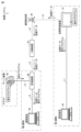
- FIG. 1 is a diagram showing an overall configuration of an air conditioning system according to a first embodiment
- FIG. 2 is a diagram showing a functional configuration of the air conditioning system according to the first embodiment
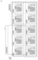
- 4 is a diagram showing an example of an air conditioning management screen displayed in the air conditioning system according to the first embodiment
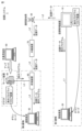
- FIG. FIG. 2 is a diagram showing an example of data communication in the air conditioning system according to the first embodiment
- FIG. 11 is a diagram showing an example of an air conditioning management screen displayed in the air conditioning system according to the second embodiment.
- FIG. 13 is a diagram showing an example of an air conditioning management screen displayed in the air conditioning system according to the third embodiment.
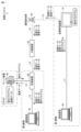
- FIG. 11 is a diagram showing an example of data communication in an air conditioning system according to the third embodiment.
- FIG. 13 is a diagram showing an example of data communication during normal communication in the air conditioning system according to the fifth embodiment.
- FIG. 13 is a diagram showing an example of data communication during a communication abnormality in the air conditioning system according to the fifth embodiment.
- FIG. 1 is a diagram showing the overall configuration of the air conditioning system 1 according to embodiment 1.
- the air conditioning system 1 includes at least one air conditioner 60, an air conditioning management device 10, a local terminal 20, a remote terminal 30, and a server device 40.
- the air conditioner 60 includes an outdoor unit 61 and an indoor unit 62, and adjusts the temperature or humidity of air drawn in from an indoor space by circulating a refrigerant in the outdoor unit 61 and the indoor unit 62, and supplies the adjusted air to the indoor space.
- multiple indoor units 62 are connected to one outdoor unit, and one air conditioner 60 is made up of one outdoor unit 61 and one indoor unit 62.
- the air conditioning management device 10 is connected to at least one air conditioner 60 and manages at least one air conditioner 60.
- the air conditioning management device 10 communicates with at least one air conditioner 60 to obtain air conditioning data related to the air conditioning of the at least one air conditioner 60 and control the at least one air conditioner 60.
- the air conditioning management device 10 is connected to multiple outdoor units 61 and obtains air conditioning data from each outdoor unit 61 and controls each outdoor unit 61.
- the local terminal 20 is, for example, an information terminal such as a desktop PC (Personal Computer), a laptop PC, or a tablet PC, or a mobile terminal such as a smartphone that is individually owned by a user.
- the local terminal 20 is communicatively connected to the air conditioning management device 10 via the communication line L1.
- the local terminal 20 is capable of acquiring air conditioning data from the air conditioning management device 10 via the communication line L1.
- the remote terminal 30 is, for example, an information terminal such as a desktop PC, a laptop PC, or a tablet PC, or a mobile terminal such as a smartphone owned individually by a user.
- the remote terminal 30 is configured to be able to communicate with the air conditioning management device 10 via a communication line L2.
- the remote terminal 30 is connected to a terminal device 80 (described later) in the cloud via a communication line L3, and the terminal device 80 is communicatively connected to the air conditioning management device 10 via a communication base station 50 and the communication line L2. That is, the remote terminal 30 is communicatively connected to the air conditioning management device 10 using the communication line L2 and the communication line L3 via the terminal device 80 and the communication base station 50.
- the remote terminal 30 is able to acquire air conditioning data from the air conditioning management device 10 via the communication line L2 and the communication line L3.
- the server device 40 is a cloud-type server device composed of information terminals such as PCs.
- the server device 40 is configured to be able to communicate with the air conditioning management device 10 using the communication line L2 via the communication base station 50.
- the server device 40 like the remote terminal 30, is connected to be able to communicate with the air conditioning management device 10 using the communication line L2 and the communication line L3 via the termination device 80 and the communication base station 50.
- the communication line L1 is an example of a "first communication line.”
- the communication line L1 is a fixed line using a wired LAN such as an optical line or a wireless LAN such as Wi-Fi, and can transmit large amounts of data at high speed between the local terminal 20 and the air conditioning management device 10.
- the local terminal 20 is located within a range where communication with the air conditioning management device 10 is possible using a fixed line or wireless LAN.
- the local terminal 20 and the air conditioning management device 10 are located in the same first building.
- the remote terminal 30 is located in a second building different from the air conditioning management device 10 and the local terminal 20.
- the local terminal 20 may be capable of performing data communication via the Internet, but is configured to perform data communication with the air conditioning management device 10 via the communication line L1 using a wired LAN or wireless LAN without using the Internet.
- the communication line L2 is an example of a "second communication line.”
- the communication line L2 is a communication line for IoT (Internet of Things) provided by a virtual mobile communications operator.
- the communication line L2 may be an ISDN (Integrated Services Digital Network), an ADSL (Asymmetric Digital Subscriber Line), or any other Internet line with an upper limit on at least one of the communication speed and communication volume. While communication using the communication line L2 has the advantage of being inexpensive, it also has the disadvantage of being slow and having an upper limit on the communication volume that can be used in a month.
- the communication line L3 is an example of a "third communication line.”
- the communication line L3 is a fixed line using a wired LAN such as an optical line, or a communication line using a wireless LAN such as Wi-Fi, and can transmit large volumes of data at high speed between the remote terminal 30 and the server device 40 via the termination device 80 described below.
- Communication line L2 is more restricted in at least one of the communication volume and communication speed than communication line L1 and communication line L3. For example, there is no upper limit on the communication volume of each of communication line L1 and communication line L3, or the upper limit is higher than the upper limit on the communication volume of communication line L2.
- the upper limit on the communication volume of communication line L2 is determined in advance and is lower than the upper limit on the communication volume of each of communication line L1 and communication line L3.
- FIG. 2 is a diagram showing the functional configuration of the air conditioning system 1 according to the first embodiment.
- the air conditioning system 1 includes an air conditioning management device 10 and a local terminal 20 located in a first building, a remote terminal 30 and a terminal device 80 located in a second building, and a server device 40 and a relay device 70 on the cloud.
- the air conditioning management device 10 includes a control device 11, a memory 12, a storage device 13, a display 14, an input device 15, an external communication unit 16, a local communication unit 17, and an equipment communication unit 18.
- the control device 11 is a computing entity (computer) that executes various processes by executing various programs.
- the control device 11 is composed of a processor such as a CPU (central processing unit) or an MPU (micro-processing unit).
- the processor which is an example of the control device 11, has the function of executing various processes by executing programs, but some or all of these functions may be implemented using a dedicated hardware circuit such as an ASIC (application specific integrated circuit) or an FPGA (field-programmable gate array).
- ASIC application specific integrated circuit
- FPGA field-programmable gate array
- the term "processor” is not limited to a processor in the narrow sense that executes processes using a stored program method such as a CPU or an MPU, but may also include hardwired circuits such as an ASIC or an FPGA. For this reason, the "processor", which is an example of the control device 11, may also be interpreted as a processing circuit in which processing is defined in advance by computer-readable code and/or hardwired circuits.
- the control device 11 may be
- the memory 12 includes a volatile storage area (e.g., a working area) that temporarily stores program code or work memory when the control device 11 executes various programs.
- Examples of memory 12 include volatile memory such as DRAM (dynamic random access memory) and SRAM (static random access memory), or non-volatile memory such as ROM (Read Only Memory) and flash memory.
- the storage device 13 stores various programs and various data executed by the control device 11. For example, as shown in FIG. 2, the storage device 13 stores a display program executed by the control device 11 (a program configured in HTML or CSS, etc.) and air conditioning data referenced by the control device 11.
- the storage device 13 may be one or more non-transitory computer readable mediums, or one or more computer readable storage mediums. Examples of storage device 13 include a hard disk drive (HDD) and a solid state drive (SSD).
- the display 14 displays a predetermined screen according to the control of the control device 11.
- the control device 11 executes a display program to generate a default screen for the air conditioning management screen described later in FIG. 3, and inputs air conditioning data into the default screen to generate the air conditioning management screen, and displays the air conditioning management screen on the display 14.
- the input device 15 is an operation unit for accepting specific information input by a user, and includes a mouse, keyboard, or touch panel.
- the external communication unit 16 is an interface for communicating with the relay device 70 via the communication line L2 via the communication base station 50.
- the air conditioning management device 10 is equipped with a SIM (Subscriber Identity Module) card (not shown) and can communicate with the relay device 70 via the communication line L2 provided by a virtual mobile communications operator that is generally used by mobile terminals and the like.
- the control device 11 transmits air conditioning data to the relay device 70 by communicating with the relay device 70 using the communication line L2 via the external communication unit 16.
- the local communication unit 17 is an interface for communicating with the local communication unit 27 of the local terminal 20 via the communication line L1.
- the control device 11 transmits air conditioning data to the local terminal 20 by communicating with the local terminal 20 via the local communication unit 17.
- the device communication unit 18 is an interface for connecting to the air conditioner 60.
- the control device 11 communicates with the air conditioner 60 via the device communication unit 18 to receive air conditioning data from the air conditioner 60 and transmit control data to the air conditioner 60.
- the local terminal 20 includes a control device 21, a memory 22, a storage device 23, a display 24, an input device 25, and a local communication unit 27.
- the control device 21 is a computing entity (computer) that executes various processes by running various programs.
- the control device 21 has a configuration similar to that of the control device 11, and is composed of, for example, a processor.
- a "processor,” which is an example of the control device 21, can also be interpreted as a processing circuit, in which processing is defined in advance by computer-readable code and/or hardwired circuits.
- Memory 22 includes a volatile storage area (e.g., a working area) that temporarily stores program code or work memory when control device 21 executes various programs.
- Memory 22 has a similar configuration to memory 12, and is composed of, for example, volatile memory or non-volatile memory.
- the storage device 23 stores various programs or various data executed by the control device 21.
- the storage device 23 has a configuration similar to that of the storage device 13, and may be one or more non-transitory computer readable mediums, or one or more computer readable storage mediums.
- the display 24 displays a predetermined screen according to the control of the control device 21.
- the display 24 displays an air conditioning management screen, which will be described later, that is generated based on the air conditioning data and a display program.
- the input device 25 is an operation unit for accepting specific information input by the user, and includes a mouse, keyboard, or touch panel.
- the local communication unit 27 is an interface for communicating with the local communication unit 17 of the air conditioning management device 10 via the communication line L1.
- the control device 21 receives air conditioning data from the air conditioning management device 10 by communicating with the air conditioning management device 10 via the local communication unit 27.
- the remote terminal 30 includes a control device 31, a memory 32, a storage device 33, a display 34, an input device 35, and an external communication unit 36.
- the control device 31 is a computing entity (computer) that executes various processes by running various programs.
- the control device 31 has a configuration similar to that of the control device 11, and is, for example, configured with a processor.
- a "processor,” which is an example of the control device 31, can also be interpreted as a processing circuit, in which processing is defined in advance by computer-readable code and/or hardwired circuits.
- Memory 32 includes a volatile storage area (e.g., a working area) that temporarily stores program code or work memory when control device 31 executes various programs.
- Memory 32 has a similar configuration to memory 12 and is composed of, for example, volatile memory or non-volatile memory.
- the storage device 33 stores various programs or various data executed by the control device 31.
- the storage device 33 has a configuration similar to that of the storage device 13, and may be one or more non-transitory computer readable mediums, or one or more computer readable storage mediums.
- the display 34 displays a predetermined screen according to the control of the control device 31.
- the display 34 displays an air conditioning management screen, which will be described later, that is generated based on the air conditioning data and a display program.
- the input device 35 is an operation unit for accepting specific information input by the user, and includes a mouse, keyboard, or touch panel.
- the external communication unit 36 is an interface for communicating with the external communication unit 46 of the server device 40 via the terminal device 80 and the communication line L3, and for communicating with the relay device 70 via the terminal device 80 and the communication line L2.
- the control device 31 receives air conditioning data from the air conditioning management device 10 by communicating with the relay device 70 via the external communication unit 36.
- the server device 40 includes a control device 41, a memory 42, a storage device 43, and an external communication unit 46.
- the control device 41 is a computing entity (computer) that executes various processes by running various programs.
- the control device 41 has a configuration similar to that of the control device 11, and is composed of, for example, a processor.
- a "processor,” which is an example of the control device 41, can also be interpreted as a processing circuit, in which processing is defined in advance by computer-readable code and/or hardwired circuits.
- Memory 42 includes a volatile storage area (e.g., a working area) that temporarily stores program code or work memory when control device 41 executes various programs.
- Memory 42 has a similar configuration to memory 12 and is composed of, for example, volatile memory or non-volatile memory.
- the storage device 43 stores various programs or various data executed by the control device 41.
- the storage device 43 has a configuration similar to that of the storage device 13, and may be one or more non-transitory computer readable mediums, or one or more computer readable storage mediums.
- the external communication unit 46 is an interface for communicating with the external communication unit 36 of the remote terminal 30 via the terminal device 80 and the communication line L3, and for communicating with the relay device 70 via the terminal device 80 and the communication line L2.
- the relay device 70 is located between the communication base station 50 and the termination device 80, and communicates with the communication base station 50 via the communication line L2, and also communicates with the termination device 80 via the communication line L2.
- the termination device 80 is located between the remote terminal 30 and the server device 40 and the relay device 70, and communicates with the remote terminal 30 and the server device 40 via communication line L3, and with the relay device 70 via communication line L2.
- the air conditioning management device 10 the local terminal 20, and the remote terminal 30 are each capable of displaying a common screen generated based on the air conditioning data.
- FIG. 3 is a diagram showing an example of an air conditioning management screen displayed in the air conditioning system according to embodiment 1.
- FIG. 3 shows a common default screen displayed on the display 14 of the air conditioning management device 10, the display 24 of the local terminal 20, and the display 34 of the remote terminal 30, and a common air conditioning management screen generated by inputting air conditioning data into the default screen.
- the air conditioning data relating to each air conditioner 60 is displayed on the air conditioning management screen.
- the air conditioning management device 10, the local terminal 20, and the remote terminal 30 each generate a default screen by executing a display program.
- the default screen is, for example, a standard screen in which the air conditioning data for the air conditioners 60 installed in each room is blanked out, and the air conditioning data is displayed in the blank areas of each air conditioner 60, allowing the user to check the air conditioning data for each air conditioner 60.
- the air conditioning management device 10, the local terminal 20, and the remote terminal 30 each generate an air conditioning management screen by inputting air conditioning data into the default screen, and display the air conditioning management screen on each display 14, 24, 34. Note that the default screen and air conditioning management screen are not limited to the example of FIG. 3 and may be displayed in other forms.
- an air conditioning management screen is generated using a common display program in each of the air conditioning management device 10, the local terminal 20, and the remote terminal 30, the user can display the air conditioning management screen common to the air conditioning management device 10 using a terminal that can use a browser, such as a PC or a smartphone, such as the local terminal 20 and the remote terminal 30.
- the user does not need to install a dedicated application for displaying the air conditioning management screen in the local terminal 20 and the remote terminal 30, and can easily display the air conditioning management screen using a standard web browser.
- the local terminal 20, and the remote terminal 30 by displaying a common air conditioning management screen in the air conditioning management device 10, the local terminal 20, and the remote terminal 30, it is only necessary to learn how to operate one air conditioning management screen, and there is no need to learn different operation methods for the air conditioning management device 10, the local terminal 20, and the remote terminal 30, improving user convenience.
- the air conditioning management screen displays air conditioning data for air conditioner A installed in room A, air conditioner B installed in the break room, air conditioner C installed in room B, air conditioner D installed in conference room A, air conditioner E installed in the president's office, and air conditioner F installed in conference room B.
- the air conditioning data includes the set temperature, room temperature, pipe temperature, power consumption, etc. This air conditioning data is detected by sensors (not shown) and acquired by the air conditioning management device 10.
- the air conditioning system 1 is configured so that the air conditioning management device 10, the local terminal 20, and the remote terminal 30 each display a common air conditioning management screen generated based on the display program and air conditioning data.
- the local terminal 20 and the remote terminal 30 display an air conditioning management screen such as that shown in FIG. 3 on a web browser, they need to use not only air conditioning data but also a display program.
- the display program is a program for displaying a graphical interface screen, the amount of communication is greater than that of air conditioning data such as numerical values.
- the local terminal 20 is located within a range where a LAN connection with the air conditioning management device 10 is possible (for example, within the first building), and therefore can obtain air conditioning data and a display program from the air conditioning management device 10 via a communication line L1 that is capable of high-volume communication using a fixed line or wireless LAN. Therefore, even if the local terminal 20 receives air conditioning data and a display program from the air conditioning management device 10 every time it attempts to display the air conditioning management screen, there is no risk that the amount of communication consumed will reach the upper limit of the amount of communication available early.
- the remote terminal 30 since the remote terminal 30 is located outside the range where a LAN connection with the air conditioning management device 10 is possible (for example, inside the second building), it cannot use the communication line L1, which is capable of large-volume communication, and must obtain the air conditioning data and display program from the air conditioning management device 10 via the communication line L2, which is provided by a virtual mobile communications operator and has a limited communication volume or communication speed. For this reason, if the remote terminal 30 attempts to receive the air conditioning data and display program from the air conditioning management device 10 every time it attempts to display the air conditioning management screen, there is a risk that the amount of communication consumed will reach the upper limit of the available communication volume early or the communication time will be long. As a result, the remote terminal 30 may not be able to properly receive the air conditioning data and display program from the air conditioning management device 10, or the reception time may be extended, causing it to take a long time to display the air conditioning management screen.
- the air conditioning system 1 is configured so that the display program is stored in advance in the server device 40, and the remote terminal 30 acquires the display program from the server device 40 via the communication line L3 while acquiring the air conditioning data from the air conditioning management device 10 via the communication line L2.
- FIG 4 is a diagram showing an example of data communication in the air conditioning system 1 according to embodiment 1.
- the air conditioning management device 10 stores a display program in the storage device 13
- the server device 40 also stores a display program in advance in the storage device 43.
- the server device 40 may obtain the display program in advance from the air conditioning management device 10 via the communication line L2, or may obtain the display program in advance from a work terminal other than the air conditioning management device 10.
- the local terminal 20 acquires the air conditioning data and the display program from the air conditioning management device 10 via the communication line L1.
- the local terminal 20 generates a default screen by executing the display program, and generates an air conditioning management screen by inputting the air conditioning data into the default screen, and displays the air conditioning management screen on the display 24.
- the remote terminal 30 obtains a display program from the server device 40 via communication line L3, and obtains air conditioning data from the air conditioning management device 10 via communication line L2.
- the remote terminal 30 generates a default screen by executing the display program, and generates an air conditioning management screen by inserting air conditioning data into the default screen, and displays the air conditioning management screen on the display 34.
- the remote terminal 30 obtains the display program for generating a standard default screen from the server device 40, not the air conditioning management device 10, regardless of the content of the air conditioning data, and obtains the air conditioning data that can change depending on the operating state of the air conditioner 60 from the air conditioning management device 10.
- the remote terminal 30 acquires air conditioning data using the communication line L2, which has at least one of the communication volume and communication speed limited more than the communication line L1, while acquiring the display program, which has a larger communication volume than the air conditioning data, from the server device 40 using the communication line L3, thereby making it possible to display an air conditioning management screen common to the local terminal 20 while reducing communication costs using the communication line L2 provided by the virtual mobile communications carrier.
- the air conditioning system 1 can reduce only the communication volume between the air conditioning management device 10 and the remote terminal 30 without reducing functions related to the display of the air conditioning management screen, and can provide the user with an air conditioning management screen having a common interface among the air conditioning management device 10, the local terminal 20, and the remote terminal 30.
- the air conditioning management screen in FIG. 3 was shown as an example of a common screen displayed on the air conditioning management device 10, the local terminal 20, and the remote terminal 30, but other types of screens may be used as long as they are screens for displaying air conditioning data.
- the air conditioning management screen in FIG. 3 is a screen for the user to view air conditioning data, but it may also be a screen on which the user can set the operating state of the air conditioner 60 (for example, the set temperature, etc.).
- FIG. 5 is a diagram showing an example of an air conditioning management screen displayed in the air conditioning system 1 according to embodiment 2.
- the remote terminal 30 obtains the air conditioning data from the air conditioning management device 10 via the communication line L2, so it is preferable that the amount of communication of the air conditioning data be as small as possible.
- the air conditioning data includes multiple types of data such as the set temperature, room temperature, pipe temperature, and power consumption, but if all of this data is sent from the air conditioning management device 10 to the remote terminal 30 on a regular basis without omission, there is a risk that the amount of communication of the air conditioning data will increase.
- the air conditioning system 1 is configured so that the types of air conditioning data acquired by the remote terminal 30 from the air conditioning management device 10 are the same as the types of air conditioning data acquired by the local terminal 20 from the air conditioning management device 10, or are fewer than the types of air conditioning data acquired by the local terminal 20 from the air conditioning management device 10.
- the remote terminal 30 may request only the air conditioning data desired by the user from the multiple types of air conditioning data based on user input acquired by the input device 35, and the air conditioning management device 10 may transmit only the air conditioning data desired by the user requested from the remote terminal 30 to the remote terminal 30.
- the remote terminal 30 may acquire only the air conditioning data desired by the user from the air conditioning management device 10 and reflect it on the air conditioning management screen.
- the local terminal 20 acquires all of the set temperature, room temperature, pipe temperature, and power consumption from the air conditioning management device 10 and reflects them on the air conditioning management screen
- the remote terminal 30 acquires only the set temperature, room temperature, and power consumption excluding the pipe temperature from the air conditioning management device 10 and reflects them on the air conditioning management screen.
- the user can obtain only the air conditioning data that the user considers necessary for management purposes from the air conditioning management device 10 and display it on the remote terminal 30, thereby reducing the amount of air conditioning data transmitted from the air conditioning management device 10 to the remote terminal 30 via the communication line L2.
- the user may set the type of air conditioning data that the remote terminal 30 will reflect on the air conditioning management screen using the input device 15 of the air conditioning management device 10, not limited to the input device 35 of the remote terminal 30.
- the air conditioning management device 10 may transmit only the air conditioning data desired by the user out of multiple types of air conditioning data based on user input acquired by the input device 15 to the remote terminal 30, and the remote terminal 30 may acquire only the air conditioning data desired by the user from the air conditioning management device 10 and reflect it on the air conditioning management screen.
- the air conditioning system 1 according to the second embodiment may be configured so that the frequency with which the remote terminal 30 acquires air conditioning data from the air conditioning management device 10 is the same as the frequency with which the local terminal 20 acquires air conditioning data from the air conditioning management device 10, or is lower than the frequency with which the local terminal 20 acquires air conditioning data from the air conditioning management device 10.
- the remote terminal 30 may set the frequency at which it requests air conditioning data from the air conditioning management device 10 based on user input acquired by the input device 35. Furthermore, the remote terminal 30 may set the frequency at which it requests air conditioning data for each of multiple types of air conditioning data based on user input acquired by the input device 35.
- the air conditioning management device 10 may periodically transmit each piece of air conditioning data to the remote terminal 30 according to the frequency specified by the remote terminal 30.
- the remote terminal 30 may obtain the air conditioning data periodically transmitted from the air conditioning management device 10 and reflect it on the air conditioning management screen.
- the local terminal 20 obtains each piece of air conditioning data, such as the set temperature, indoor temperature, pipe temperature, and power consumption, from the air conditioning management device 10 every minute and reflects them on the air conditioning management screen
- the remote terminal 30 obtains the set temperature from the air conditioning management device 10 every minute, the indoor temperature from the air conditioning management device 10 every 10 minutes, and the power consumption from the air conditioning management device 10 every hour, and periodically reflects them on the air conditioning management screen.
- the user can reduce the amount of air conditioning data transmitted from the air conditioning management device 10 to the remote terminal 30 via the communication line L2 by increasing the update frequency of air conditioning data that the user considers necessary to check frequently for management reasons, while decreasing the update frequency of air conditioning data that the user considers unnecessary to check frequently.
- the user may use the input device 15 of the air conditioning management device 10, not limited to the input device 35 of the remote terminal 30, to set the frequency at which the remote terminal 30 reflects the air conditioning data on the air conditioning management screen.
- the air conditioning management device 10 may transmit each type of air conditioning data to the remote terminal 30 at a frequency set for each type of air conditioning data based on user input acquired by the input device 15, and the remote terminal 30 may periodically acquire each type of air conditioning data from the air conditioning management device 10 and reflect it on the air conditioning management screen.
- the air conditioning system 1 can keep the communication volume of air conditioning data that the remote terminal 30 acquires from the air conditioning management device 10 lower than the communication volume of air conditioning data that the local terminal 20 acquires from the air conditioning management device 10. This allows the air conditioning system 1 to display an air conditioning management screen on the remote terminal 30 that reflects the air conditioning data desired by the user, while reducing communication costs by utilizing the communication line L2 provided by the virtual mobile communications operator.
- FIG. 6 is a diagram showing an example of an air conditioning management screen displayed in the air conditioning system 1 according to embodiment 3.
- multiple air conditioners 60 may be connected to the air conditioning management device 10.
- the air conditioning management device 10 may be connected to the air conditioning management device 10.
- the air conditioning system 1 is configured so that the remote terminal 30 acquires from the air conditioning management device 10 only the air conditioning data relating to at least one air conditioner 60 included in the screen being displayed on the display 34 of the remote terminal 30.
- the remote terminal 30 can display on the display 34 a floor image showing a floor in a building on which an air conditioner 60 is installed.
- the user can increase or decrease the number of air conditioners 60 included in the air conditioning management screen displayed on the display 34 by using the input device 35 (e.g., a touch panel) to drag and move the floor image displayed on the display 34, pinch in to shrink it, or pinch out to enlarge it.
- the remote terminal 30 may request from the air conditioning management device 10 only air conditioning data related to the air conditioner 60 included in the floor image that has been moved, reduced, or enlarged on the screen of the display 34 by the user's operation, and the air conditioning management device 10 may transmit to the remote terminal 30 only the air conditioning data requested by the remote terminal 30.
- the remote terminal 30 may obtain only the air conditioning data desired by the user from the air conditioning management device 10 and reflect it on the air conditioning management screen.
- the remote terminal 30 acquires only the air conditioning data relating to air conditioner A in room A, air conditioner C in room B, and air conditioner E in the president's office, which are included in the air conditioning management screen being displayed on the display 34, from the air conditioning management device 10 as update targets, and reflects this data on the air conditioning management screen.
- the remote terminal 30 does not acquire air conditioning data relating to air conditioner B, air conditioner D, and air conditioners F to J, which are not included in the air conditioning management screen being displayed on the display 34, from the air conditioning management device 10 as not being update targets, and does not reflect this data on the air conditioning management screen.
- the remote terminal 30 may acquire important data that is more important than the air conditioning data (for example, abnormality data for air conditioner 60) from the air conditioning management device 10 as update targets, even if the data is for air conditioner B, air conditioner D, and air conditioners F to J, which are not included in the air conditioning management screen being displayed on the display 34.
- air conditioning data for example, abnormality data for air conditioner 60
- FIG. 6 shows an air conditioning management screen displayed on the display 34 of the remote terminal 30, but even in the air conditioning management screen displayed on the display 24 of the local terminal 20, only the air conditioning data displayed by the user's dragging, pinching in, or pinching out may be reflected on the air conditioning management screen.
- FIG. 7 is a diagram showing an example of data communication in the air conditioning system 1 according to the third embodiment.
- the local terminal 20 acquires a floor image from the air conditioning management device 10.
- the local terminal 20 can acquire only the air conditioning data displayed by the user's dragging, pinching in, or pinching out from the air conditioning management device 10 and reflect it on the air conditioning management screen.
- the user uses the work terminal 90 to upload a floor image from the work terminal 90 to the server device 40.
- the user may also use the air conditioning management device 10 or the local terminal 20 to upload a floor image from the air conditioning management device 10 or the local terminal 20 to the server device 40.
- the remote terminal 30 acquires the floor image from the server device 40.
- the remote terminal 30 can acquire only the air conditioning data displayed by the user's dragging, pinching in, or pinching out from the air conditioning management device 10 and reflect it on the air conditioning management screen.
- the remote terminal 30 can reduce the amount of communication of air conditioning data acquired from the air conditioning management device 10 by acquiring only the air conditioning data related to the air conditioners 60 included in the floor image displayed on the display 34 from the air conditioning management device 10, without acquiring air conditioning data related to all air conditioners 60 from the air conditioning management device 10.
- FIG. 8 is a diagram showing an example of data communication in the air conditioning system 1 according to embodiment 4.
- the air conditioning system 1 includes multiple remote terminals 30, and each remote terminal 30 displays the air conditioning data acquired from the air conditioning management device 10.
- each remote terminal 30 individually acquires air conditioning data from the air conditioning management device 10
- the air conditioning management device 10 will end up sending the same air conditioning data to each remote terminal 30, which is wasteful in terms of reducing communication traffic.
- the air conditioning system 1 is configured such that at least one remote terminal 30 among the multiple remote terminals 30 is a parent device and the other remote terminals 30 are child devices, with only the parent device acquiring air conditioning data from the air conditioning management device 10 and the child devices acquiring air conditioning data from the parent device. Furthermore, if the parent device is unable to communicate with the air conditioning management device 10, at least one child device included in the child devices may be promoted to a parent device and acquire air conditioning data from the air conditioning management device 10.
- the air conditioning system 1 has multiple remote terminals 30A, 30B, and 30C in the second building.
- remote terminal 30A is set as a parent unit
- remote terminals 30B and 30C are set as child units.
- Remote terminal 30A is an example of a "first remote terminal” and can communicate with air conditioning management device 10 via communication line L2 and communication line L3.
- Remote terminals 30B and 30C are an example of a "second remote terminal” and can communicate with remote terminal 30A via communication line L3.
- Remote terminal 30A obtains air conditioning data from air conditioning management device 10.
- Remote terminals 30B and 30C obtain air conditioning data from remote terminal 30A, not from air conditioning management device 10. If remote terminal 30A is unable to communicate with air conditioning management device 10, remote terminal 30B or remote terminal 30C is promoted to the parent device and acquires air conditioning data from air conditioning management device 10.
- the air conditioning management device 10 can reduce the amount of communication of air conditioning data sent by the air conditioning management device 10 to the remote terminals 30 by sending the air conditioning data only to at least one remote terminal 30 that is the parent device, without sending the air conditioning data individually to each of the multiple remote terminals 30.
- Embodiment 5 An air conditioning system 1 according to embodiment 5 will be described with reference to Figures 9 and 10. Note that, for the air conditioning system 1 according to embodiment 5, only configurations and functions that are different from the air conditioning system 1 according to embodiment 1 will be described, and descriptions of configurations and functions that are common to the air conditioning system 1 according to embodiment 1 may be omitted.
- each of the remote terminal 30 and the local terminal 20 may acquire important data that is more important than the air conditioning data from the air conditioning management device 10 in addition to the air conditioning data.
- the important data includes, for example, anomaly information regarding an abnormality in at least one air conditioner 60.
- anomaly information includes information that is useful for analyzing when an air conditioner 60 is malfunctioning or broken.
- FIG. 9 is a diagram showing an example of data communication during normal communication in the air conditioning system 1 according to embodiment 5.
- the local terminal 20 acquires air conditioning data and important data from the air conditioning management device 10 via communication line L1, and displays the acquired air conditioning data and important data on the display 24. This allows the user to check the air conditioning data and important data using the local terminal 20.
- the remote terminal 30 acquires air conditioning data and important data from the air conditioning management device 10 via communication line L2, and displays the acquired air conditioning data and important data on the display 34. This allows the user to check the air conditioning data and important data using the remote terminal 30 in the same way as the local terminal 20.
- FIG. 10 is a diagram showing an example of data communication during a communication abnormality in the air conditioning system 1 according to embodiment 5.
- the remote terminal 30 when there is an abnormality in communication on the communication line L2, the remote terminal 30 cannot acquire the air conditioning data and important data from the air conditioning management device 10, and therefore cannot display the air conditioning data and important data on the display 34.
- abnormalities in the air conditioner 60 may include abnormalities with a high degree of urgency, such as a refrigerant leak, it is preferable to display important data on the display 34 as much as possible.
- the server device 40 acquires important data from the air conditioning management device 10 via communication line L2 and stores it in the storage device 43. Then, as shown in FIG. 10, when communication on communication line L2 is abnormal, the remote terminal 30 acquires important data from the server device 40 via communication line L3, not from the air conditioning management device 10, and displays it on the display 34.
- the remote terminal 30 may determine that a communication abnormality has occurred on the communication line L2.
- the remote terminal 30 when the remote terminal 30 is unable to obtain important data from the air conditioning management device 10 due to a communication abnormality on communication line L2, it can obtain important data cached in the server device 40 via communication line L3 and display it on the display 34. As a result, even if a communication abnormality occurs on communication line L2, the user can check the important data immediately before the communication abnormality occurred using the remote terminal 30. Furthermore, when communication on communication line L2 is normal, the remote terminal 30 obtains important data from the air conditioning management device 10, thereby reducing the access load on the server device 40.
- Embodiment 6 An air conditioning system 1 according to embodiment 6 will be described. Note that, for the air conditioning system 1 according to embodiment 6, only configurations and functions different from those of the air conditioning system 1 according to embodiment 1 will be described, and descriptions of configurations and functions common to the air conditioning system 1 according to embodiment 1 may be omitted.
- the display program stored in the server device 40 While the display program stored in the server device 40 is always updated to the latest version, the display program stored in the air conditioning management device 10 may remain at an old version from the time the air conditioning management device 10 was installed. In such cases, the screen of the remote terminal 30 displayed using the display program obtained from the server device 40 may differ from the screen of the local terminal 20 displayed using the display program obtained from the air conditioning management device 10.
- the air conditioning data acquired by the remote terminal 30 from the air conditioning management device 10 may include version information indicating the version of the display program stored by the air conditioning management device 10. Furthermore, the remote terminal 30 may compare the version of the display program stored by the air conditioning management device 10 with the version of the display program acquired from the server device 40 based on the version information, and if the two are different, execute a notification process to make the version of the display program stored by the air conditioning management device 10 and the version of the display program acquired from the server device 40 the same.
- the remote terminal 30 may display a screen to notify the user that the version of the display program stored in the air conditioning management device 10 is different from the version of the display program acquired from the server device 40, or may display a screen to prompt the user to update the version of the display program stored in the air conditioning management device 10 to the latest version, the same as the version of the display program acquired from the server device 40.
- the user can check, from the screen displayed on the remote terminal 30, whether the version of the display program stored in the air conditioning management device 10 is the same as the version of the display program acquired from the server device 40, and if the two are different, the version of the display program stored in the air conditioning management device 10 can be updated to the same latest version as the version of the display program acquired from the server device 40.
- the air conditioning management device 10 communicates with the server device 40, the user can download the latest version of the display program from the server device 40 to the air conditioning management device 10, thereby making the version of the display program stored in the air conditioning management device 10 the same as the version of the display program acquired from the server device 40.
- the remote terminal 30 can make the version of the display program acquired from the server device 40 the same as the version of the display program stored by the air conditioning management device 10, and can display a screen that is common to the local terminal 20.
- the air conditioning system 1 of the present disclosure includes at least one air conditioner 60, an air conditioning management device 10 that manages the at least one air conditioner 60, a local terminal 20 that can communicate with the air conditioning management device 10 via a communication line L1, at least one remote terminal 30 that can communicate with the air conditioning management device 10 via a communication line L2, and a server device 40 that can communicate with the at least one remote terminal 30 via a communication line L3.
- the communication line L2 is more limited in at least one of the communication amount and the communication speed than each of the communication lines L1 and L3.
- the air conditioning management device 10 stores air conditioning data related to at least one air conditioner 60 and a display program for displaying the air conditioning data.
- the server device 40 stores the display program.
- the local terminal 20 acquires the air conditioning data and the display program from the air conditioning management device 10 via the communication line L1, and displays the air conditioning data based on the acquired air conditioning data and the display program.
- At least one remote terminal 30 acquires air conditioning data from the air conditioning management device 10 via communication line L2, while acquiring a display program from the server device 40 via communication line L3, and displays the air conditioning data based on the acquired air conditioning data and display program.
- the remote terminal 30 can obtain air conditioning data from the air conditioning management device 10 via communication line L2, which has at least one of the communication volume and communication speed limited more than communication line L1, while obtaining the display program from the server device 40 via communication line L3, which has at least one of the communication volume and communication speed not limited more than communication line L2.
- This makes it possible to display a screen that is common to the local terminal 20 while using communication line L2, which has at least one of the communication volume and communication speed limited more than communication line L1.
- Communication line L2 is a communication line provided by a virtual mobile communications operator.
- the remote terminal 30 can obtain air conditioning data from the air conditioning management device 10 via the communication line L2 provided by the virtual mobile communications carrier, while obtaining the display program from the server device 40 via the communication line L3, making it possible to display a screen that is common to the local terminal 20 while utilizing the communication line L2 provided by the virtual mobile communications carrier.
- the communication line L1 is a communication line that uses a wireless LAN or a wired LAN.
- the remote terminal 30 can obtain air conditioning data from the air conditioning management device 10 via communication line L2, which has at least one of the communication volume and communication speed limited more than communication line L1 using a wireless LAN or wired LAN, while obtaining the display program from the server device 40 via communication line L3, so that a screen common to the local terminal 20 can be displayed while using communication line L2.
- the display program requires more communication than the air conditioning data.
- the remote terminal 30 can obtain air conditioning data from the air conditioning management device 10 via communication line L2, while obtaining the display program, which requires a larger amount of communication traffic than the air conditioning data, from the server device 40 via communication line L3. This makes it possible to display a screen that is the same as the local terminal 20 while using communication line L2.
- the types of air conditioning data that at least one remote terminal 30 acquires from the air conditioning management device 10 are the same as the types of air conditioning data that the local terminal 20 acquires from the air conditioning management device 10, or are fewer than the types of air conditioning data that the local terminal 20 acquires from the air conditioning management device 10.
- the remote terminal 30 obtains and displays only the air conditioning data that the user considers necessary from the air conditioning management device 10, thereby reducing the amount of communication of air conditioning data obtained from the air conditioning management device 10 via the communication line L2.
- the frequency with which at least one remote terminal 30 acquires air conditioning data from the air conditioning management device 10 is the same as the frequency with which the local terminal 20 acquires air conditioning data from the air conditioning management device 10, or is lower than the frequency with which the local terminal 20 acquires air conditioning data from the air conditioning management device 10.
- the remote terminal 30 can reduce the amount of communication of air conditioning data acquired from the air conditioning management device 10 via the communication line L2 by increasing the update frequency of air conditioning data that the user considers necessary to check frequently, while decreasing the update frequency of air conditioning data that the user considers unnecessary to check frequently.
- At least one remote terminal 30 acquires only air conditioning data related to at least one air conditioner 60 included in the currently displayed screen from the air conditioning management device 10.
- the remote terminal 30 can reduce the amount of communication of air conditioning data acquired from the air conditioning management device 10 by acquiring only the air conditioning data related to the air conditioner 60 included in the floor image displayed on the display 34 from the air conditioning management device 10.
- At least one remote terminal 30 includes remote terminal 30A capable of communicating with air conditioning management device 10, and remote terminals 30B and 30C capable of communicating with remote terminal 30A.
- Remote terminal 30A acquires air conditioning data from air conditioning management device 10.
- Remote terminals 30B and 30C acquire air conditioning data from remote terminal 30A.
- the air conditioning management device 10 can reduce the amount of communication of air conditioning data sent by the air conditioning management device 10 to the remote terminals 30A, 30B, and 30C by sending the air conditioning data only to at least one remote terminal 30A, which is the parent device, without sending the air conditioning data individually to each of the multiple remote terminals 30A, 30B, and 30C.
- the air conditioning data includes version information indicating the version of the display program stored by the air conditioning management device 10.
- At least one remote terminal 30 compares the version of the display program stored by the air conditioning management device 10 with the version of the display program acquired from the server device 40 based on the version information.
- At least one remote terminal 30 executes a notification process to make the version of the display program stored by the air conditioning management device 10 and the version of the display program acquired from the server device 40 the same.
- the remote terminal 30 can make the version of the display program acquired from the server device 40 the same as the version of the display program stored by the air conditioning management device 10. For example, if the version of the display program stored by the air conditioning management device 10 is older than the version of the display program acquired from the server device 40, the version of the display program stored by the air conditioning management device 10 can be updated to display a screen that is common to the local terminal 20.
- server device 40 acquires and stores important data, which is more important than air conditioning data, from air conditioning management device 10 via communication line L2.
- at least one remote terminal 30 acquires important data from air conditioning management device 10 via communication line L2, and when communication line L2 is abnormal, acquires important data from server device 40.
- the remote terminal 30 when the remote terminal 30 is unable to obtain important data from the air conditioning management device 10 due to a communication abnormality on the communication line L2, it can obtain the important data stored in the server device 40 via the communication line L3 and display it on the display 34. Therefore, even if a communication abnormality occurs on the communication line L2, the important data immediately before the communication abnormality occurs can be displayed on the display 34. Furthermore, since the remote terminal 30 obtains important data from the air conditioning management device 10 when communication on the communication line L2 is normal, the access load on the server device 40 can be reduced.
- the important data includes abnormality information regarding an abnormality in at least one air conditioner.
- the remote terminal 30 can display on the display 34 abnormality information regarding the abnormality in the air conditioner immediately before the communication abnormality occurred.
- the air conditioning systems 1 according to each of the first to sixth embodiments have been described above, but the configurations and functions of each air conditioning system 1 may be combined.
- one air conditioning system 1 may have all of the configurations and functions of the air conditioning systems 1 according to each of the first to sixth embodiments.
- 1 air conditioning system 10 air conditioning management device, 11, 21, 31, 41 control device, 12, 22, 32, 42 memory, 13, 23, 33, 43 storage device, 14, 24, 34 display, 15, 25, 35 input device, 16, 36, 46 external communication unit, 17, 27 local communication unit, 18 device communication unit, 20 local terminal, 30, 30A, 30B, 30C remote terminal, 40 server device, 50 communication base station, 60 air conditioner, 61 outdoor unit, 62 indoor unit, 70 relay device, 80 termination device, 90 work terminal, L1, L2, L3 communication line.
Landscapes
- Engineering & Computer Science (AREA)
- Human Computer Interaction (AREA)
- Chemical & Material Sciences (AREA)
- Combustion & Propulsion (AREA)
- Mechanical Engineering (AREA)
- General Engineering & Computer Science (AREA)
- Air Conditioning Control Device (AREA)
Abstract
空調システム(1)は、空調機(60)と、空調管理装置(10)と、現地端末(20)と、遠隔端末(30)と、サーバ装置(40)とを備える。通信回線(L2)は、通信回線(L1)および通信回線(L3)の各々よりも、通信量および通信速度のうちの少なくとも1つが制限されている。現地端末(20)は、通信回線(L1)を介して空調管理装置(10)から空調データと表示プログラムとを取得し、空調データと表示プログラムとに基づき空調データを表示する。遠隔端末(30)は、通信回線(L2)を介して空調管理装置(10)から空調データを取得する一方で通信回線(L3)を介してサーバ装置(40)から表示プログラムを取得し、取得した空調データと表示プログラムとに基づき空調データを表示する。
Description
本開示は、空調システムに関する。
従来、空調機を管理する空調管理装置と、空調管理装置と通信可能な端末とを備えるシステムが公知である。たとえば、特許6419203号公報(特許文献1)には、空調機を管理する空調管理装置とPCまたは携帯端末などの現地端末とがWi-Fiなどの無線LAN(Local Area Network)または有線LANなどの通信回線を介して通信可能に接続された管理システムが開示されている。この管理システムによれば、ユーザは、現地端末を利用して空調管理装置から空調機の運転データを取得することができる。
特許6419203号公報に開示されたシステムは、空調管理装置とLAN接続可能な範囲内(たとえば、同じ建物内など)に位置する現地端末を用いて空調管理装置と通信することを想定しているが、近年、LAN接続可能な範囲外に位置する遠隔端末を用いて空調管理装置と通信するようなシステムも提供されている。このようなシステムは、仮想移動体通信事業者(MVNO:Mobile Virtual Network Operator)によって提供されるような通信量または通信速度に上限が予め定められた低速かつ低容量の通信回線を介して、空調管理装置から離れた場所から遠隔端末を用いて空調管理装置と通信するように構成されている場合がある。このようなシステムにおいて、現地端末と共通の画面を遠隔端末にも表示させる場合、仮想移動体通信事業者によって提供される通信量または通信速度が制限された通信回線を利用して表示用のプログラムを空調管理装置から遠隔端末にその都度送信すると、利用可能な通信量の上限に消費通信量が早期に到達したり、通信時間が長くなったりするおそれがある。
本開示は、上記課題を解決するためになされたものであって、通信量または通信速度が制限された通信回線を利用して、遠隔端末が現地端末と共通の画面を表示することを可能とする技術を提供することを目的とする。
本開示に係る空調システムは、少なくとも1つの空調機と、少なくとも1つの空調機を管理する空調管理装置と、第1通信回線を介して空調管理装置と通信可能な現地端末と、第2通信回線を介して空調管理装置と通信可能な少なくとも1つの遠隔端末と、第3通信回線を介して少なくとも1つの遠隔端末と通信可能なサーバ装置とを備える。第2通信回線は、第1通信回線および第3通信回線の各々よりも、通信量および通信速度のうちの少なくとも1つが制限されている。空調管理装置は、少なくとも1つの空調機に関する空調データと空調データを表示するための表示プログラムとを記憶する。サーバ装置は、表示プログラムを記憶する。現地端末は、第1通信回線を介して空調管理装置から空調データと表示プログラムとを取得し、取得した空調データと表示プログラムとに基づき空調データを表示する。少なくとも1つの遠隔端末は、第2通信回線を介して空調管理装置から空調データを取得する一方で第3通信回線を介してサーバ装置から表示プログラムを取得し、取得した空調データと表示プログラムとに基づき空調データを表示する。
本開示の空調システムによれば、遠隔端末は、空調データについては、第1通信回線よりも通信量および通信速度のうちの少なくとも1つが制限された第2通信回線を介して空調管理装置から取得する一方で、表示プログラムについては、第2通信回線よりも通信量および通信速度のうちの少なくとも1つが制限されていない第3通信回線を介してサーバ装置から取得することができるため、第1通信回線よりも通信量および通信速度のうちの少なくとも1つが制限された第2通信回線を利用しながら、現地端末と共通の画面を表示することができる。
以下、本開示の実施の形態について、図面を参照しながら詳細に説明する。以下では、複数の実施の形態について説明するが、各実施の形態で説明された構成を適宜組み合わせることは出願当初から予定されている。なお、図中同一または相当部分には同一符号を付してその説明は繰り返さない。
実施の形態1.
図1~図4を参照しながら、実施の形態1に係る空調システム1を説明する。図1は、実施の形態1に係る空調システム1の全体構成を示す図である。図1に示すように、空調システム1は、少なくとも1つの空調機60と、空調管理装置10と、現地端末20と、遠隔端末30と、サーバ装置40とを備える。
図1~図4を参照しながら、実施の形態1に係る空調システム1を説明する。図1は、実施の形態1に係る空調システム1の全体構成を示す図である。図1に示すように、空調システム1は、少なくとも1つの空調機60と、空調管理装置10と、現地端末20と、遠隔端末30と、サーバ装置40とを備える。
空調機60は、室外機61と室内機62とを備え、室外機61および室内機62の中で冷媒を循環させることによって、室内空間から吸い込んだ空気の温度または湿度などを調整し、調整済みの空気を室内空間に供給する。図1の例では、1つの室外機に複数の室内機62が接続されており、1つの室外機61と1つの室内機62とによって1つの空調機60が構成されている。
空調管理装置10は、少なくとも1つの空調機60に接続されており、少なくとも1つの空調機60を管理する。たとえば、空調管理装置10は、少なくとも1つの空調機60と通信することで、少なくとも1つの空調機60の空調に関する空調データを取得したり、少なくとも1つの空調機60を制御したりする。図1の例では、空調管理装置10は、複数の室外機61に接続されており、各室外機61から空調データを取得したり、各室外機61を制御したりする。
現地端末20は、たとえば、デスクトップ型のPC(Personal Computer)、ラップトップ型のPC、またはタブレット型のPCなどの情報端末、あるいは、ユーザが個別に所有するスマートフォンなどの携帯端末である。現地端末20は、通信回線L1を介して、空調管理装置10と通信可能に接続されている。現地端末20は、通信回線L1を介して空調管理装置10から空調データを取得することが可能である。
遠隔端末30は、たとえば、デスクトップ型のPC、ラップトップ型のPC、またはタブレット型のPCなどの情報端末、あるいは、ユーザが個別に所有するスマートフォンなどの携帯端末である。遠隔端末30は、通信回線L2を介して、空調管理装置10と通信可能に構成されている。具体的には、遠隔端末30は、通信回線L3を介して、クラウド内の後述する終端装置80に接続されており、終端装置80は、通信基地局50を経由して、通信回線L2を介して、空調管理装置10と通信可能に接続されている。すなわち、遠隔端末30は、終端装置80および通信基地局50を経由して、通信回線L2および通信回線L3を利用して空調管理装置10と通信可能に接続されている。遠隔端末30は、通信回線L2および通信回線L3を介して空調管理装置10から空調データを取得することが可能である。
サーバ装置40は、PCなどの情報端末で構成されるクラウド型のサーバ装置である。サーバ装置40は、通信基地局50を経由して、通信回線L2を利用して空調管理装置10と通信可能に構成されている。具体的には、サーバ装置40は、遠隔端末30と同様に、終端装置80および通信基地局50を経由して、通信回線L2および通信回線L3を利用して空調管理装置10と通信可能に接続されている。
通信回線L1は、「第1通信回線」の一例である。通信回線L1は、光回線などの有線LANを利用した固定回線またはWi-Fiなどの無線LANを利用した通信回線であり、現地端末20と空調管理装置10との間で大容量のデータを高速に伝送することができる。現地端末20は、空調管理装置10との間で固定回線または無線LANを利用した通信が可能な範囲内に位置している。たとえば、現地端末20および空調管理装置10は、同じ第1建物内に位置している。一方、遠隔端末30は、空調管理装置10および現地端末20と異なる第2建物内に位置している。なお、現地端末20は、インターネットを介したデータ通信を行うことが可能であってもよいが、空調管理装置10との間においては、インターネットを介することなく、有線LANまたは無線LANを利用した通信回線L1を介して、データ通信するように構成されている。
通信回線L2は、「第2通信回線」の一例である。通信回線L2は、仮想移動体通信事業者によって提供されるIoT(Internet of Things)向けの通信回線である。なお、通信回線L2は、ISDN(Integrated Services Digital Network)、ADSL(Asymmetric Digital Subscriber Line)、または、その他の通信速度および通信量の少なくとも1つに上限が定められたインターネット回線であってもよい。通信回線L2を用いた通信は、安価であるというメリットがある一方で、低速であり、かつ、1ヶ月に利用可能な通信量に上限が定められているというデメリットもある。
通信回線L3は、「第3通信回線」の一例である。通信回線L3は、光回線などの有線LANを利用した固定回線またはWi-Fiなどの無線LANを利用した通信回線であり、後述する終端装置80を経由して、遠隔端末30とサーバ装置40との間で大容量のデータを高速に伝送することができる。
通信回線L2は、通信回線L1および通信回線L3の各々よりも、通信量および通信速度のうちの少なくとも1つが制限されている。たとえば、通信回線L1および通信回線L3の各々の通信量の上限は、設けられていないか、あるいは、通信回線L2の通信量の上限よりも大きい。通信回線L2の通信量の上限は、予め定められており、通信回線L1および通信回線L3の各々の通信量の上限よりも小さい。
図2は、実施の形態1に係る空調システム1の機能構成を示す図である。図2に示すように、空調システム1は、第1建物内に位置する空調管理装置10および現地端末20と、第2建物内に位置する遠隔端末30および終端装置80と、クラウド上のサーバ装置40および中継装置70とを備える。
空調管理装置10は、制御装置11と、メモリ12と、記憶装置13と、ディスプレイ14と、入力装置15と、外部通信部16と、ローカル通信部17と、機器通信部18とを備える。
制御装置11は、各種のプログラムを実行することで、各種の処理を実行する演算主体(コンピュータ)である。制御装置11は、たとえば、CPU(central processing unit)またはMPU(Micro-processing unit)などのプロセッサで構成されている。なお、制御装置11の一例であるプロセッサは、プログラムを実行することによって各種の処理を実行する機能を有するが、これらの機能の一部または全部を、ASIC(Application Specific Integrated Circuit)またはFPGA(Field-Programmable Gate Array)などの専用のハードウェア回路を用いて実装してもよい。「プロセッサ」は、CPUまたはMPUのようにストアードプログラム方式で処理を実行する狭義のプロセッサに限らず、ASICまたはFPGAなどのハードワイヤード回路を含み得る。このため、制御装置11の一例である「プロセッサ」は、コンピュータ読み取り可能なコードおよび/またはハードワイヤード回路によって予め処理が定義されている、処理回路(processing circuitry)と読み替えることもできる。なお、制御装置11は、1チップで構成されてもよいし、複数のチップで構成されてもよい。
メモリ12は、制御装置11が各種のプログラムを実行するにあたって、プログラムコードまたはワークメモリなどを一時的に格納する揮発性の記憶領域(たとえば、ワーキングエリア)を含む。メモリ12の一例としては、DRAM(dynamic random access memory)およびSRAM(static random access memory)などの揮発性メモリ、または、ROM(Read Only Memory)およびフラッシュメモリなどの不揮発性メモリが挙げられる。
記憶装置13は、制御装置11が実行する各種のプログラムまたは各種のデータなどを記憶する。たとえば、図2に示すように、記憶装置13は、制御装置11によって実行される表示プログラム(HTMLまたはCSSなどで構成されるプログラム)、および制御装置11が参照する空調データなどを格納する。記憶装置13は、1または複数の非一時的コンピュータ可読媒体(non-transitory computer readable medium)であってもよいし、1または複数のコンピュータ読み取り可能な記憶媒体(computer readable storage medium)であってもよい。記憶装置13の一例としては、HDD(Hard Disk Drive)およびSSD(Solid State Drive)などが挙げられる。
ディスプレイ14は、制御装置11の制御に従って、所定の画面を表示する。たとえば、制御装置11は、表示プログラムを実行して図3で後述する空調管理画面におけるデフォルト画面を生成するとともに、デフォルト画面に空調データを入力して空調管理画面を生成し、ディスプレイ14に空調管理画面を表示する。
入力装置15は、ユーザによって入力された所定の情報を受け付けるための操作部であり、マウス、キーボード、またはタッチパネルなどを含む。
外部通信部16は、通信基地局50を経由して、通信回線L2を介して中継装置70と通信するためのインターフェースである。たとえば、空調管理装置10は、図示しないSIM(Subscriber Identity Module)カードを装着し、一般的に携帯端末などが利用する仮想移動体通信事業者によって提供される通信回線L2を介して中継装置70と通信可能である。制御装置11は、外部通信部16によって通信回線L2を利用して中継装置70と通信することで、中継装置70に空調データを送信する。
ローカル通信部17は、通信回線L1を介して現地端末20のローカル通信部27と通信するためのインターフェースである。制御装置11は、ローカル通信部17を介して現地端末20と通信することで、現地端末20に空調データを送信する。
機器通信部18は、空調機60と接続するためのインターフェースである。制御装置11は、機器通信部18を介して空調機60と通信することで、空調機60からの空調データを受信したり、空調機60に制御データを送信したりする。
現地端末20は、制御装置21と、メモリ22と、記憶装置23と、ディスプレイ24と、入力装置25と、ローカル通信部27とを備える。
制御装置21は、各種のプログラムを実行することで、各種の処理を実行する演算主体(コンピュータ)である。制御装置21は、制御装置11と同様の構成を備え、たとえば、プロセッサで構成されている。制御装置21の一例である「プロセッサ」は、コンピュータ読み取り可能なコードおよび/またはハードワイヤード回路によって予め処理が定義されている、処理回路(processing circuitry)と読み替えることもできる。
メモリ22は、制御装置21が各種のプログラムを実行するにあたって、プログラムコードまたはワークメモリなどを一時的に格納する揮発性の記憶領域(たとえば、ワーキングエリア)を含む。メモリ22は、メモリ12と同様の構成を備え、たとえば、揮発性メモリまたは不揮発性メモリで構成されている。
記憶装置23は、制御装置21が実行する各種のプログラムまたは各種のデータなどを記憶する。記憶装置23は、記憶装置13と同様の構成を備え、1または複数の非一時的コンピュータ可読媒体(non-transitory computer readable medium)であってもよいし、1または複数のコンピュータ読み取り可能な記憶媒体(computer readable storage medium)であってもよい。
ディスプレイ24は、制御装置21の制御に従って、所定の画面を表示する。たとえば、ディスプレイ24は、空調データと表示プログラムとに基づき生成された後述する空調管理画面を表示する。
入力装置25は、ユーザによって入力された所定の情報を受け付けるための操作部であり、マウス、キーボード、またはタッチパネルなどを含む。
ローカル通信部27は、通信回線L1を介して空調管理装置10のローカル通信部17と通信するためのインターフェースである。制御装置21は、ローカル通信部27を介して空調管理装置10と通信することで、空調管理装置10からの空調データを受信する。
遠隔端末30は、制御装置31と、メモリ32と、記憶装置33と、ディスプレイ34と、入力装置35と、外部通信部36とを備える。
制御装置31は、各種のプログラムを実行することで、各種の処理を実行する演算主体(コンピュータ)である。制御装置31は、制御装置11と同様の構成を備え、たとえば、プロセッサで構成されている。制御装置31の一例である「プロセッサ」は、コンピュータ読み取り可能なコードおよび/またはハードワイヤード回路によって予め処理が定義されている、処理回路(processing circuitry)と読み替えることもできる。
メモリ32は、制御装置31が各種のプログラムを実行するにあたって、プログラムコードまたはワークメモリなどを一時的に格納する揮発性の記憶領域(たとえば、ワーキングエリア)を含む。メモリ32は、メモリ12と同様の構成を備え、たとえば、揮発性メモリまたは不揮発性メモリで構成されている。
記憶装置33は、制御装置31が実行する各種のプログラムまたは各種のデータなどを記憶する。記憶装置33は、記憶装置13と同様の構成を備え、1または複数の非一時的コンピュータ可読媒体(non-transitory computer readable medium)であってもよいし、1または複数のコンピュータ読み取り可能な記憶媒体(computer readable storage medium)であってもよい。
ディスプレイ34は、制御装置31の制御に従って、所定の画面を表示する。たとえば、ディスプレイ34は、空調データと表示プログラムとに基づき生成された後述する空調管理画面を表示する。
入力装置35は、ユーザによって入力された所定の情報を受け付けるための操作部であり、マウス、キーボード、またはタッチパネルなどを含む。
外部通信部36は、終端装置80を経由して、通信回線L3を介してサーバ装置40の外部通信部46と通信するとともに、終端装置80を経由して、通信回線L2を介して中継装置70と通信するためのインターフェースである。制御装置31は、外部通信部36を介して中継装置70と通信することで、空調管理装置10からの空調データを受信する。
サーバ装置40は、制御装置41と、メモリ42と、記憶装置43と、外部通信部46とを備える。
制御装置41は、各種のプログラムを実行することで、各種の処理を実行する演算主体(コンピュータ)である。制御装置41は、制御装置11と同様の構成を備え、たとえば、プロセッサで構成されている。制御装置41の一例である「プロセッサ」は、コンピュータ読み取り可能なコードおよび/またはハードワイヤード回路によって予め処理が定義されている、処理回路(processing circuitry)と読み替えることもできる。
メモリ42は、制御装置41が各種のプログラムを実行するにあたって、プログラムコードまたはワークメモリなどを一時的に格納する揮発性の記憶領域(たとえば、ワーキングエリア)を含む。メモリ42は、メモリ12と同様の構成を備え、たとえば、揮発性メモリまたは不揮発性メモリで構成されている。
記憶装置43は、制御装置41が実行する各種のプログラムまたは各種のデータなどを記憶する。記憶装置43は、記憶装置13と同様の構成を備え、1または複数の非一時的コンピュータ可読媒体(non-transitory computer readable medium)であってもよいし、1または複数のコンピュータ読み取り可能な記憶媒体(computer readable storage medium)であってもよい。
外部通信部46は、終端装置80を経由して、通信回線L3を介して遠隔端末30の外部通信部36と通信するとともに、終端装置80を経由して、通信回線L2を介して中継装置70と通信するためのインターフェースである。
中継装置70は、通信基地局50と終端装置80との間に位置し、通信回線L2を介して通信基地局50と通信するとともに、通信回線L2を介して終端装置80と通信する。
終端装置80は、遠隔端末30およびサーバ装置40の各々と中継装置70との間に位置し、通信回線L3を介して遠隔端末30およびサーバ装置40の各々と通信するとともに、通信回線L2を介して中継装置70と通信する。
上述のように構成された空調システム1においては、空調管理装置10、現地端末20、および遠隔端末30の各々が、空調データに基づき生成された共通の画面を表示することが可能である。
図3は、実施の形態1に係る空調システムにおいて表示される空調管理画面の一例を示す図である。図3には、空調管理装置10のディスプレイ14、現地端末20のディスプレイ24、および遠隔端末30のディスプレイ34において表示される共通のデフォルト画面と、デフォルト画面に空調データが入力されることで生成される共通の空調管理画面とが示されている。空調管理画面には、各空調機60に関する空調データが示される。
空調管理装置10、現地端末20、および遠隔端末30各々は、表示プログラムを実行することでデフォルト画面を生成する。デフォルト画面は、たとえば、各部屋に設置された空調機60における空調データがブランクになったような定型の画面であり、各空調機60におけるブランク部分に空調データが示されることで、ユーザは、各空調機60の空調データを確認することができる。空調管理装置10、現地端末20、および遠隔端末30のそれぞれは、デフォルト画面に空調データを入力することで空調管理画面を生成して、各ディスプレイ14,24,34に空調管理画面を表示する。なお、デフォルト画面および空調管理画面は、図3の例に限らず、その他の形態で表示されてもよい。
このように、空調管理装置10、現地端末20、および遠隔端末30の各々において、共通の表示プログラムを用いて空調管理画面を生成すれば、ユーザは、現地端末20および遠隔端末30のようなPCまたはスマートフォンなどのブラウザを使用可能な端末を用いて、空調管理装置10と共通の空調管理画面を表示することができる。また、ユーザは、現地端末20および遠隔端末30において、空調管理画面を表示するための専用のアプリケーションをインストールすることが不要であり、標準のWebブラウザを用いて容易に空調管理画面を表示することができる。さらに、空調管理装置10、現地端末20、および遠隔端末30において共通の空調管理画面を表示することによって、1つの空調管理画面における操作方法を学習するだけで済み、空調管理装置10、現地端末20、および遠隔端末30で異なる操作方法を学習する必要がなく、ユーザの利便性が向上する。
図3に示すように、空調管理画面には、部屋Aに設置された空調機A、休憩室に設置された空調機B、部屋Bに設置された空調機C、会議室Aに設置された空調機D、社長室に設置された空調機E、および会議室Bに設置された空調機Fの各々に関する空調データが示される。空調データは、設定温度、室内温度、配管温度、および消費電力などを含む。これらの空調データは、図示しないセンサなどによって検出され、空調管理装置10によって取得される。
このように、空調システム1は、空調管理装置10、現地端末20、および遠隔端末30の各々が、表示プログラムおよび空調データに基づき生成された共通の空調管理画面を表示するように構成されている。
ここで、上述したように、現地端末20および遠隔端末30は、Webブラウザ上で図3に示すような空調管理画面を表示する場合、空調データのみならず、表示プログラムを用いる必要がある。しかも、表示プログラムは、グラフィカルなインターフェース画面を表示させるためのプログラムであるため、数値などの空調データよりも、通信量が大きい。
現地端末20は、空調管理装置10とLAN接続可能な範囲内(たとえば、第1建物内)に位置するため、固定回線または無線LANを利用した大容量通信が可能な通信回線L1を介して空調管理装置10から空調データおよび表示プログラムを取得することが可能である。このため、現地端末20が空調管理画面を表示しようとする度に空調管理装置10から空調データおよび表示プログラムを受信した場合でも、利用可能な通信量の上限に消費通信量が早期に到達するおそれは生じない。
一方、遠隔端末30は、空調管理装置10とLAN接続可能な範囲外(たとえば、第2建物内)に位置するため、大容量通信が可能な通信回線L1を利用することはできず、仮想移動体通信事業者によって提供される通信量または通信速度が制限された通信回線L2を介して空調管理装置10から空調データおよび表示プログラムを取得する必要がある。このため、遠隔端末30が空調管理画面を表示しようとする度に空調管理装置10から空調データおよび表示プログラムを受信しようとした場合、利用可能な通信量の上限に消費通信量が早期に到達したり、通信時間が長くなったりするおそれがある。その結果、遠隔端末30は、空調管理装置10から空調データおよび表示プログラムを正常に受信することができなくなったり、受信時間が長期化することで、空調管理画面の表示に時間が掛かったりするおそれがある。
そこで、実施の形態1に係る空調システム1は、表示プログラムを予めサーバ装置40に記憶させるとともに、遠隔端末30が通信回線L2を介して空調管理装置10から空調データを取得する一方で通信回線L3を介してサーバ装置40から表示プログラムを取得するように構成されている。
図4を参照しながら、実施の形態1に係る空調システム1におけるデータ通信を説明する。図4は、実施の形態1に係る空調システム1におけるデータ通信の一例を示す図である。図4に示すように、空調システム1においては、空調管理装置10が記憶装置13に表示プログラムを記憶するとともに、サーバ装置40も記憶装置43に表示プログラムを予め記憶する。なお、サーバ装置40は、通信回線L2を介して空調管理装置10から予め表示プログラムを取得してもよいし、空調管理装置10以外の作業用端末から予め表示プログラムを取得してもよい。
現地端末20は、通信回線L1を介して空調管理装置10から空調データと表示プログラムとを取得する。現地端末20は、表示プログラムを実行することでデフォルト画面を生成するとともに、デフォルト画面に空調データを入力することで空調管理画面を生成して、ディスプレイ24に空調管理画面を表示する。
遠隔端末30は、通信回線L3を介してサーバ装置40から表示プログラムを取得するとともに、通信回線L2を介して空調管理装置10から空調データを取得する。遠隔端末30は、表示プログラムを実行することでデフォルト画面を生成するとともに、デフォルト画面に空調データを挿入することで空調管理画面を生成して、ディスプレイ34に空調管理画面を表示する。すなわち、遠隔端末30は、空調データの内容に関わらず、定型のデフォルト画面を生成するための表示プログラムについては、空調管理装置10ではなくサーバ装置40から取得し、空調機60の運転状態に応じて変化し得る空調データについては、空調管理装置10から取得する。
このように、遠隔端末30は、通信回線L1よりも通信量および通信速度のうちの少なくとも1つが制限された通信回線L2を利用して空調データを取得する一方で、空調データよりも通信量が大きい表示プログラムについては通信回線L3を利用してサーバ装置40から取得することで、仮想移動体通信事業者によって提供される通信回線L2を利用して通信コストを低減しながら、現地端末20と共通の空調管理画面を表示することができる。すなわち、空調システム1は、仮想移動体通信事業者によって提供される安価な通信回線L2を用いて空調管理装置10と遠隔端末30との間で通信する場合でも、空調管理画面の表示に関する機能を削減することなく空調管理装置10と遠隔端末30との間の通信量のみを削減することができ、空調管理装置10、現地端末20、および遠隔端末30において共通のインターフェースを有する空調管理画面をユーザに提供することができる。
なお、上述した例では、空調管理装置10、現地端末20、および遠隔端末30において表示される共通の画面として、図3の空調管理画面を例示したが、空調データを表示するための画面であれば、その他の形態の画面であってもよい。たとえば、図3の空調管理画面は、ユーザが空調データを閲覧するための画面であったが、ユーザが空調機60の運転状態(たとえば、設定温度など)を設定可能な画面であってもよい。
実施の形態2.
図5を参照しながら、実施の形態2に係る空調システム1を説明する。なお、実施の形態2に係る空調システム1については、実施の形態1に係る空調システム1と異なる構成および機能のみを説明し、実施の形態1に係る空調システム1と共通する構成および機能については説明を省略する場合がある。図5は、実施の形態2に係る空調システム1において表示される空調管理画面の一例を示す図である。
図5を参照しながら、実施の形態2に係る空調システム1を説明する。なお、実施の形態2に係る空調システム1については、実施の形態1に係る空調システム1と異なる構成および機能のみを説明し、実施の形態1に係る空調システム1と共通する構成および機能については説明を省略する場合がある。図5は、実施の形態2に係る空調システム1において表示される空調管理画面の一例を示す図である。
遠隔端末30は、通信回線L2を介して空調管理装置10から空調データを取得するため、空調データの通信量は極力小さい方が好ましい。たとえば、空調データは、設定温度、室内温度、配管温度、および消費電力などの複数種類のデータを含むが、これら全てのデータを漏れなく定期的に空調管理装置10から遠隔端末30に送信すると、空調データの通信量が増大するおそれがある。
そこで、実施の形態2に係る空調システム1は、遠隔端末30が空調管理装置10から取得する空調データの種類を、現地端末20が空調管理装置10から取得する空調データの種類と同じ、または現地端末20が空調管理装置10から取得する空調データの種類よりも少なくするように構成されている。
たとえば、遠隔端末30は、入力装置35によって取得したユーザ入力に基づいて、複数種類の空調データのうち、ユーザが所望する空調データのみを空調管理装置10に要求し、空調管理装置10は、遠隔端末30から要求されたユーザが所望する空調データのみを遠隔端末30に送信してもよい。遠隔端末30は、ユーザが所望する空調データのみを空調管理装置10から取得して、空調管理画面に反映させてもよい。
図5の例では、現地端末20は、設定温度、室内温度、配管温度、および消費電力の全てを空調管理装置10から取得して空調管理画面に反映させるのに対して、遠隔端末30は、配管温度以外の設定温度、室内温度、および消費電力のみを空調管理装置10から取得して、空調管理画面に反映させている。
このように、ユーザは、管理上、自身が必要だと考える空調データのみを空調管理装置10から取得して遠隔端末30に表示させることで、通信回線L2を介して空調管理装置10から遠隔端末30に送信される空調データの通信量を低減させることができる。
なお、ユーザは、遠隔端末30の入力装置35に限らず、空調管理装置10の入力装置15を用いて、遠隔端末30が空調管理画面に反映させる空調データの種類を設定してもよい。この場合、空調管理装置10は、入力装置15によって取得したユーザ入力に基づいて、複数種類の空調データのうち、ユーザが所望する空調データのみを遠隔端末30に送信し、遠隔端末30は、ユーザが所望する空調データのみを空調管理装置10から取得して、空調管理画面に反映させてもよい。
また、実施の形態2に係る空調システム1は、遠隔端末30が空調管理装置10から空調データを取得する頻度を、現地端末20が空調管理装置10から空調データを取得する頻度と同じ、または現地端末20が空調管理装置10から空調データを取得する頻度よりも低くするように構成されてもよい。
たとえば、遠隔端末30は、入力装置35によって取得したユーザ入力に基づいて、空調管理装置10に対して空調データを要求する頻度を設定してもよい。さらに、遠隔端末30は、入力装置35によって取得したユーザ入力に基づいて、複数種類の空調データごとに、空調データを要求する頻度を設定してもよい。空調管理装置10は、遠隔端末30によって指定された頻度に応じて、各空調データを遠隔端末30に定期的に送信してもよい。遠隔端末30は、空調管理装置10から定期的に送信される空調データを取得して、空調管理画面に反映させてもよい。
図5の例では、現地端末20は、設定温度、室内温度、配管温度、および消費電力の各空調データを空調管理装置10から毎分取得して空調管理画面に反映させるのに対して、遠隔端末30は、設定温度を空調管理装置10から毎分取得し、室内温度を空調管理装置10から10分ごとに取得し、かつ消費電力を空調管理装置10から毎時取得して、空調管理画面に定期的に反映させている。
このように、ユーザは、管理上、自身が頻繁に確認する必要があると考える空調データの更新頻度を上げる一方で、自身が頻繁に確認する必要がないと考える空調データの更新頻度を下げることで、通信回線L2を介して空調管理装置10から遠隔端末30に送信される空調データの通信量を低減させることができる。
なお、ユーザは、遠隔端末30の入力装置35に限らず、空調管理装置10の入力装置15を用いて、遠隔端末30が空調データを空調管理画面に反映させる頻度を設定してもよい。この場合、空調管理装置10は、入力装置15によって取得したユーザ入力に基づいて、複数種類の空調データごとに設定された頻度で各空調データを遠隔端末30に送信し、遠隔端末30は、空調管理装置10から定期的に各空調データを取得して、空調管理画面に反映させてもよい。
このように、空調システム1は、現地端末20が空調管理装置10から取得する空調データの通信量よりも、遠隔端末30が空調管理装置10から取得する空調データの通信量を小さく抑えることができる。これにより、空調システム1は、仮想移動体通信事業者によって提供される通信回線L2を利用して通信コストを低減しながら、ユーザが所望する空調データを反映させた空調管理画面を遠隔端末30に表示させることができる。
実施の形態3.
図6および図7を参照しながら、実施の形態3に係る空調システム1を説明する。なお、実施の形態3に係る空調システム1については、実施の形態1に係る空調システム1と異なる構成および機能のみを説明し、実施の形態1に係る空調システム1と共通する構成および機能については説明を省略する場合がある。図6は、実施の形態3に係る空調システム1において表示される空調管理画面の一例を示す図である。
図6および図7を参照しながら、実施の形態3に係る空調システム1を説明する。なお、実施の形態3に係る空調システム1については、実施の形態1に係る空調システム1と異なる構成および機能のみを説明し、実施の形態1に係る空調システム1と共通する構成および機能については説明を省略する場合がある。図6は、実施の形態3に係る空調システム1において表示される空調管理画面の一例を示す図である。
空調管理装置10には、たとえば、100台規模の複数の空調機60が接続されることがあるが、図3の空調管理画面が表示されるディスプレイ34のサイズに限界があることを考慮すれば、全ての空調機60に関する空調データを1つの空調管理画面の範囲内に表示させることは難しい。
そこで、実施の形態3に係る空調システム1は、遠隔端末30のディスプレイ34に表示中の画面に含まれる少なくとも1つの空調機60に関する空調データのみを、遠隔端末30が空調管理装置10から取得するように構成されている。
たとえば、図6に示すように、遠隔端末30は、空調機60が設置される建物内のフロアを示すフロア画像をディスプレイ34に表示することができる。ユーザは、ディスプレイ34に表示されたフロア画像を入力装置35(たとえば、タッチパネル)を用いてドラッグによって移動したり、ピンチインによって縮小したり、ピンチアウトによって拡大したりすることで、ディスプレイ34に表示中の空調管理画面に含まれる空調機60の数を増減させることができる。遠隔端末30は、ユーザの操作によってディスプレイ34の画面上で移動、縮小、または拡大したフロア画像に含まれる空調機60に関する空調データのみを空調管理装置10に要求し、空調管理装置10は、遠隔端末30から要求された空調データのみを遠隔端末30に送信してもよい。遠隔端末30は、ユーザが所望する空調データのみを空調管理装置10から取得して、空調管理画面に反映させてもよい。
図6の例では、遠隔端末30は、ディスプレイ34に表示中の空調管理画面に含まれる部屋Aの空調機A、部屋Bの空調機C、および社長室の空調機Eに関する空調データのみを更新対象として空調管理装置10から取得して、空調管理画面に反映させている。一方、遠隔端末30は、ディスプレイ34に表示中の空調管理画面に含まれない、空調機B、空調機D、空調機F~Jに関する空調データを更新対象外として空調管理装置10から取得せず、空調管理画面に反映させない。なお、遠隔端末30は、空調データよりも重要な重要データ(たとえば、空調機60の異常データ)については、ディスプレイ34に表示中の空調管理画面に含まれない、空調機B、空調機D、空調機F~Jであっても、更新対象として空調管理装置10から取得してもよい。
なお、図6の例は、遠隔端末30のディスプレイ34に表示された空調管理画面を示しているが、現地端末20のディスプレイ24に表示された空調管理画面においても、ユーザのドラッグ、ピンチイン、またはピンチアウトによって表示された空調データのみが空調管理画面に反映されてもよい。
図7を参照しながら、実施の形態3に係る空調システム1におけるデータ通信について具体的に説明する。図7は、実施の形態3に係る空調システム1におけるデータ通信の一例を示す図である。図7に示すように、現地端末20は、空調管理装置10からフロア画像を取得する。これにより、現地端末20は、ディスプレイ24にフロア画像を表示することで、ユーザのドラッグ、ピンチイン、またはピンチアウトによって表示された空調データのみを空調管理装置10から取得して空調管理画面に反映させることができる。
一方、ユーザは、作業用端末90を用いて、作業用端末90からサーバ装置40にフロア画像をアップロードする。なお、ユーザは、空調管理装置10または現地端末20を用いて、空調管理装置10または現地端末20からサーバ装置40にフロア画像をアップロードしてもよい。遠隔端末30は、サーバ装置40からフロア画像を取得する。これにより、遠隔端末30は、ディスプレイ34にフロア画像を表示することで、ユーザのドラッグ、ピンチイン、またはピンチアウトによって表示された空調データのみを空調管理装置10から取得して空調管理画面に反映させることができる。
このように、遠隔端末30は、全ての空調機60に関する空調データを空調管理装置10から取得することなく、ディスプレイ34に表示されたフロア画像に含まれる空調機60に関する空調データのみを空調管理装置10から取得することで、空調管理装置10から取得する空調データの通信量を低減することができる。
実施の形態4.
図8を参照しながら、実施の形態4に係る空調システム1を説明する。なお、実施の形態4に係る空調システム1については、実施の形態1に係る空調システム1と異なる構成および機能のみを説明し、実施の形態1に係る空調システム1と共通する構成および機能については説明を省略する場合がある。図8は、実施の形態4に係る空調システム1におけるデータ通信の一例を示す図である。
図8を参照しながら、実施の形態4に係る空調システム1を説明する。なお、実施の形態4に係る空調システム1については、実施の形態1に係る空調システム1と異なる構成および機能のみを説明し、実施の形態1に係る空調システム1と共通する構成および機能については説明を省略する場合がある。図8は、実施の形態4に係る空調システム1におけるデータ通信の一例を示す図である。
たとえば、空調システム1が複数の遠隔端末30を備え、各遠隔端末30が空調管理装置10から取得した空調データを表示するようなシステムも想定される。ここで、各遠隔端末30が個別に空調管理装置10から空調データを取得する場合、空調管理装置10は、同じ空調データを各遠隔端末30に送信することになり、通信量を低減させることを鑑みれば無駄が多い。
そこで、実施の形態4に係る空調システム1は、複数の遠隔端末30のうち、少なくとも1つの遠隔端末30を親機とし、かつ、その他の遠隔端末30を子機として、親機のみが空調管理装置10から空調データを取得するとともに、子機は親機から空調データを取得するように構成されている。さらに、親機が空調管理装置10との間で通信不能になった場合、子機に含まれる少なくとも1つの子機が親機に昇格して、空調管理装置10から空調データを取得してもよい。
たとえば、図8に示すように、空調システム1は、第2建物内に複数の遠隔端末30A,30B,30Cを備える。複数の遠隔端末30A,30B,30Cのうち、遠隔端末30Aは親機に設定され、遠隔端末30B,30Cは子機に設定されている。遠隔端末30Aは、「第1遠隔端末」の一例であり、通信回線L2および通信回線L3を介して空調管理装置10と通信可能である。遠隔端末30B,30Cは、「第2遠隔端末」の一例であり、通信回線L3を介して遠隔端末30Aと通信可能である。遠隔端末30Aは、空調管理装置10から空調データを取得する。遠隔端末30B,30Cは、空調管理装置10からではなく、遠隔端末30Aから空調データを取得する。なお、遠隔端末30Aが空調管理装置10との間で通信不能になった場合、遠隔端末30Bまたは遠隔端末30Cが親機に昇格して、空調管理装置10から空調データを取得する。
このように、空調管理装置10は、複数の遠隔端末30の各々に対して個別に空調データを送信することなく、親機である少なくとも1つの遠隔端末30のみに対して空調データを送信することで、空調管理装置10が遠隔端末30に対して送信する空調データの通信量を低減することができる。
実施の形態5.
図9および図10を参照しながら、実施の形態5に係る空調システム1を説明する。なお、実施の形態5に係る空調システム1については、実施の形態1に係る空調システム1と異なる構成および機能のみを説明し、実施の形態1に係る空調システム1と共通する構成および機能については説明を省略する場合がある。
図9および図10を参照しながら、実施の形態5に係る空調システム1を説明する。なお、実施の形態5に係る空調システム1については、実施の形態1に係る空調システム1と異なる構成および機能のみを説明し、実施の形態1に係る空調システム1と共通する構成および機能については説明を省略する場合がある。
たとえば、空調システム1において、遠隔端末30および現地端末20の各々は、空調データの他に、空調データよりも重要な重要データを空調管理装置10から取得してもよい。重要データは、たとえば、少なくとも1つの空調機60の異常に関する異常情報を含む。このような異常情報は、空調機60の不良または故障時の解析に役立つ情報を含む。
図9は、実施の形態5に係る空調システム1における通信正常時のデータ通信の一例を示す図である。図9に示すように、現地端末20は、通信回線L1を介して空調管理装置10から空調データおよび重要データを取得し、取得した空調データおよび重要データをディスプレイ24に表示する。これにより、ユーザは、現地端末20を用いて空調データおよび重要データを確認することができる。一方、遠隔端末30は、通信回線L2を介して空調管理装置10から空調データおよび重要データを取得し、取得した空調データおよび重要データをディスプレイ34に表示する。これにより、ユーザは、遠隔端末30を用いても、現地端末20と同様に空調データおよび重要データを確認することができる。
図10は、実施の形態5に係る空調システム1における通信異常時のデータ通信の一例を示す図である。図10に示すように、通信回線L2の通信が異常である場合、遠隔端末30は空調管理装置10から空調データおよび重要データを取得することができないため、空調データおよび重要データをディスプレイ34に表示することができない。ここで、空調機60の異常には、冷媒漏洩などの緊急度の高い異常が含まれる場合もあるため、可能な限り重要データをディスプレイ34に表示することが好ましい。
そこで、実施の形態5に係る空調システム1においては、図9に示すように、サーバ装置40は、通信回線L2の通信正常時に、通信回線L2を介して空調管理装置10から重要データを取得して、記憶装置43に記憶する。そして、図10に示すように、遠隔端末30は、通信回線L2の通信異常時に、空調管理装置10からではなく、通信回線L3を介してサーバ装置40から重要データを取得してディスプレイ34に表示する。
なお、遠隔端末30は、空調管理装置10から定期的に送信されるPINGPONGおよびハートビートと称される応答信号を所定期間を超えて受信しなかった場合に、通信回線L2の通信異常が発生したと判断すればよい。
このように、遠隔端末30は、通信回線L2の通信異常によって空調管理装置10から重要データを取得することができない場合に、サーバ装置40でキャッシュされた重要データを通信回線L3を介して取得してディスプレイ34に表示することができる。これにより、ユーザは、通信回線L2の通信異常が発生した場合でも、通信異常が発生した直前の重要データについては、遠隔端末30によって確認することができる。また、遠隔端末30は、通信回線L2の通信正常時では、空調管理装置10から重要データを取得するため、サーバ装置40に対するアクセス負荷を軽減することができる。
実施の形態6.
実施の形態6に係る空調システム1を説明する。なお、実施の形態6に係る空調システム1については、実施の形態1に係る空調システム1と異なる構成および機能のみを説明し、実施の形態1に係る空調システム1と共通する構成および機能については説明を省略する場合がある。
実施の形態6に係る空調システム1を説明する。なお、実施の形態6に係る空調システム1については、実施の形態1に係る空調システム1と異なる構成および機能のみを説明し、実施の形態1に係る空調システム1と共通する構成および機能については説明を省略する場合がある。
サーバ装置40に記憶された表示プログラムは、常に最新のバージョンに更新される一方で、空調管理装置10に記憶された表示プログラムは、空調管理装置10が設置された当時の古いバージョンのままになっていることがある。このような場合、サーバ装置40から取得した表示プログラムを用いて表示される遠隔端末30の画面と、空調管理装置10から取得した表示プログラムを用いて表示される現地端末20の画面とが異なる場合があり得る。
そこで、実施の形態6に係る空調システム1において、遠隔端末30が空調管理装置10から取得する空調データは、空調管理装置10によって記憶された表示プログラムのバージョンを示すバージョン情報を含んでいてもよい。また、遠隔端末30は、バージョン情報に基づき、空調管理装置10によって記憶された表示プログラムのバージョンと、サーバ装置40から取得した表示プログラムのバージョンとを比較し、両者が異なる場合に、空調管理装置10によって記憶された表示プログラムのバージョンと、サーバ装置40から取得した表示プログラムのバージョンとを同じにするための報知処理を実行してもよい。
たとえば、遠隔端末30は、報知処理として、空調管理装置10に記憶された表示プログラムのバージョンと、サーバ装置40から取得した表示プログラムのバージョンとが異なることをユーザに報知するための画面を表示をしたり、空調管理装置10に記憶された表示プログラムのバージョンを、サーバ装置40から取得した表示プログラムのバージョンと同じく最新のものに更新するようにユーザに促すための画面を表示をしたりしてもよい。
このようにすれば、ユーザは、遠隔端末30に表示された画面によって、空調管理装置10に記憶された表示プログラムのバージョンと、サーバ装置40から取得した表示プログラムのバージョンとが同じであるか否かを確認することができるとともに、両者が異なる場合は、空調管理装置10に記憶された表示プログラムのバージョンを、サーバ装置40から取得した表示プログラムのバージョンと同じく最新のものに更新することができる。たとえば、ユーザは、空調管理装置10をサーバ装置40に通信させることで、サーバ装置40から最新のバージョンの表示プログラムを空調管理装置10にダウンロードさせて、空調管理装置10に記憶された表示プログラムのバージョンと、サーバ装置40から取得した表示プログラムのバージョンとを同じにすることができる。
これにより、遠隔端末30は、サーバ装置40から取得した表示プログラムのバージョンと、空調管理装置10によって記憶される表示プログラムのバージョンとを同じにすることができるため、現地端末20と共通の画面を表示することができる。
(まとめ)
本開示の空調システム1は、少なくとも1つの空調機60と、少なくとも1つの空調機60を管理する空調管理装置10と、通信回線L1を介して空調管理装置10と通信可能な現地端末20と、通信回線L2を介して空調管理装置10と通信可能な少なくとも1つの遠隔端末30と、通信回線L3を介して少なくとも1つの遠隔端末30と通信可能なサーバ装置40とを備える。通信回線L2は、通信回線L1および通信回線L3の各々よりも、通信量および通信速度のうちの少なくとも1つが制限されている。空調管理装置10は、少なくとも1つの空調機60に関する空調データと空調データを表示するための表示プログラムとを記憶する。サーバ装置40は、表示プログラムを記憶する。現地端末20は、通信回線L1を介して空調管理装置10から空調データと表示プログラムとを取得し、取得した空調データと表示プログラムとに基づき空調データを表示する。少なくとも1つの遠隔端末30は、通信回線L2を介して空調管理装置10から空調データを取得する一方で通信回線L3を介してサーバ装置40から表示プログラムを取得し、取得した空調データと表示プログラムとに基づき空調データを表示する。
本開示の空調システム1は、少なくとも1つの空調機60と、少なくとも1つの空調機60を管理する空調管理装置10と、通信回線L1を介して空調管理装置10と通信可能な現地端末20と、通信回線L2を介して空調管理装置10と通信可能な少なくとも1つの遠隔端末30と、通信回線L3を介して少なくとも1つの遠隔端末30と通信可能なサーバ装置40とを備える。通信回線L2は、通信回線L1および通信回線L3の各々よりも、通信量および通信速度のうちの少なくとも1つが制限されている。空調管理装置10は、少なくとも1つの空調機60に関する空調データと空調データを表示するための表示プログラムとを記憶する。サーバ装置40は、表示プログラムを記憶する。現地端末20は、通信回線L1を介して空調管理装置10から空調データと表示プログラムとを取得し、取得した空調データと表示プログラムとに基づき空調データを表示する。少なくとも1つの遠隔端末30は、通信回線L2を介して空調管理装置10から空調データを取得する一方で通信回線L3を介してサーバ装置40から表示プログラムを取得し、取得した空調データと表示プログラムとに基づき空調データを表示する。
これにより、遠隔端末30は、空調データについては、通信回線L1よりも通信量および通信速度のうちの少なくとも1つが制限された通信回線L2を介して空調管理装置10から取得する一方で、表示プログラムについては、通信回線L2よりも通信量および通信速度のうちの少なくとも1つが制限されていない通信回線L3を介してサーバ装置40から取得することができるため、通信回線L1よりも通信量および通信速度のうちの少なくとも1つが制限された通信回線L2を利用しながら、現地端末20と共通の画面を表示することができる。
通信回線L2は、仮想移動体通信事業者によって提供される通信回線である。
これにより、遠隔端末30は、空調データについては、仮想移動体通信事業者によって提供される通信回線L2を介して空調管理装置10から取得する一方で、表示プログラムについては、通信回線L3を介してサーバ装置40から取得することができるため、仮想移動体通信事業者によって提供される通信回線L2を利用しながら、現地端末20と共通の画面を表示することができる。
通信回線L1は、無線LANまたは有線LANを利用した通信回線である。
これにより、遠隔端末30は、空調データについては、無線LANまたは有線LANを利用した通信回線L1よりも通信量および通信速度のうちの少なくとも1つが制限された通信回線L2を介して空調管理装置10から取得する一方で、表示プログラムについては、通信回線L3を介してサーバ装置40から取得することができるため、通信回線L2を利用しながら、現地端末20と共通の画面を表示することができる。
表示プログラムは、空調データよりも通信量が大きい。
これにより、遠隔端末30は、空調データについては、通信回線L2を介して空調管理装置10から取得する一方で、空調データよりも通信量が大きい表示プログラムについては、通信回線L3を介してサーバ装置40から取得することができるため、通信回線L2を利用しながら、現地端末20と共通の画面を表示することができる。
少なくとも1つの遠隔端末30が空調管理装置10から取得する空調データの種類は、現地端末20が空調管理装置10から取得する空調データの種類と同じ、または現地端末20が空調管理装置10から取得する空調データの種類よりも少ない。
これにより、遠隔端末30は、ユーザが必要だと考える空調データのみを空調管理装置10から取得して表示するため、通信回線L2を介して空調管理装置10から取得する空調データの通信量を低減することができる。
少なくとも1つの遠隔端末30が空調管理装置10から空調データを取得する頻度は、現地端末20が空調管理装置10から空調データを取得する頻度と同じ、または現地端末20が空調管理装置10から空調データを取得する頻度よりも低い。
これにより、遠隔端末30は、ユーザが頻繁に確認する必要があると考える空調データの更新頻度を上げる一方で、ユーザが頻繁に確認する必要がないと考える空調データの更新頻度を下げることで、通信回線L2を介して空調管理装置10から取得する空調データの通信量を低減することができる。
少なくとも1つの遠隔端末30は、表示中の画面に含まれる少なくとも1つの空調機60に関する空調データのみを空調管理装置10から取得する。
これにより、遠隔端末30は、ディスプレイ34に表示されたフロア画像に含まれる空調機60に関する空調データのみを空調管理装置10から取得することで、空調管理装置10から取得する空調データの通信量を低減することができる。
少なくとも1つの遠隔端末30は、空調管理装置10と通信可能な遠隔端末30Aと、遠隔端末30Aと通信可能な遠隔端末30B,30Cとを含む。遠隔端末30Aは、空調管理装置10から空調データを取得する。遠隔端末30B,30Cは、遠隔端末30Aから空調データを取得する。
これにより、空調管理装置10は、複数の遠隔端末30A、30B,30Cの各々に対して個別に空調データを送信することなく、親機である少なくとも1つの遠隔端末30Aのみに対して空調データを送信することで、空調管理装置10が遠隔端末30A、30B,30Cに対して送信する空調データの通信量を低減することができる。
空調データは、空調管理装置10によって記憶される表示プログラムのバージョンを示すバージョン情報を含む。少なくとも1つの遠隔端末30は、バージョン情報に基づき、空調管理装置10によって記憶される表示プログラムのバージョンと、サーバ装置40から取得した表示プログラムのバージョンとを比較する。
これにより、遠隔端末30は、サーバ装置40から取得した表示プログラムのバージョンと、空調管理装置10によって記憶される表示プログラムのバージョンとが同じであるか否かを判定することができる。
少なくとも1つの遠隔端末30は、空調管理装置10によって記憶される表示プログラムのバージョンと、サーバ装置40から取得した表示プログラムのバージョンとが異なる場合、空調管理装置10によって記憶される表示プログラムのバージョンと、サーバ装置40から取得した表示プログラムのバージョンとを同じにするための報知処理を実行する。
これにより、遠隔端末30は、サーバ装置40から取得した表示プログラムのバージョンと、空調管理装置10によって記憶される表示プログラムのバージョンとを同じにすることができるため、たとえば、空調管理装置10によって記憶される表示プログラムのバージョンがサーバ装置40から取得した表示プログラムのバージョンよりも古い場合、空調管理装置10によって記憶される表示プログラムのバージョンを更新することで、現地端末20と共通の画面を表示することができる。
サーバ装置40は、通信回線L2の正常時に、通信回線L2を介して空調管理装置10から空調データよりも重要な重要データを取得して記憶する。少なくとも1つの遠隔端末30は、通信回線L2の正常時に、通信回線L2を介して空調管理装置10から重要データを取得し、通信回線L2の異常時に、サーバ装置40から重要データを取得する。
これにより、遠隔端末30は、通信回線L2の通信異常によって空調管理装置10から重要データを取得することができない場合に、サーバ装置40で記憶された重要データを通信回線L3を介して取得してディスプレイ34に表示することができるため、通信回線L2の通信異常が発生した場合でも、通信異常が発生した直前の重要データをディスプレイ34に表示することができる。さらに、遠隔端末30は、通信回線L2の通信正常時では、空調管理装置10から重要データを取得するため、サーバ装置40に対するアクセス負荷を軽減することができる。
重要データは、少なくとも1つの空調機の異常に関する異常情報を含む。
これにより、遠隔端末30は、通信回線L2の通信異常が発生した場合でも、通信異常が発生した直前の空調機の異常に関する異常情報をディスプレイ34に表示することができる。
以上、実施の形態1~実施の形態6の各々に係る空調システム1について説明したが、各空調システム1が備える構成および機能は組み合わされてもよい。たとえば、1つの空調システム1が、実施の形態1~実施の形態6の各々に係る空調システム1が備える構成および機能の全てを備えてもよい。
今回開示された実施の形態は、すべての点で例示であって制限的なものではないと考えられるべきである。本開示の範囲は、上記した実施の形態の説明ではなくて請求の範囲によって示され、請求の範囲と均等の意味および範囲内でのすべての変更が含まれることが意図される。
1 空調システム、10 空調管理装置、11,21,31,41 制御装置、12,22,32,42 メモリ、13,23,33,43 記憶装置、14,24,34 ディスプレイ、15,25,35 入力装置、16,36,46 外部通信部、17,27 ローカル通信部、18 機器通信部、20 現地端末、30,30A,30B,30C 遠隔端末、40 サーバ装置、50 通信基地局、60 空調機、61 室外機、62 室内機、70 中継装置、80 終端装置、90 作業用端末、L1,L2,L3 通信回線。
Claims (12)
- 空調システムであって、
少なくとも1つの空調機と、
前記少なくとも1つの空調機を管理する空調管理装置と、
第1通信回線を介して前記空調管理装置と通信可能な現地端末と、
第2通信回線を介して前記空調管理装置と通信可能な少なくとも1つの遠隔端末と、
第3通信回線を介して前記少なくとも1つの遠隔端末と通信可能なサーバ装置とを備え、
前記第2通信回線は、前記第1通信回線および前記第3通信回線の各々よりも、通信量および通信速度のうちの少なくとも1つが制限されており、
前記空調管理装置は、前記少なくとも1つの空調機に関する空調データと前記空調データを表示するための表示プログラムとを記憶し、
前記サーバ装置は、前記表示プログラムを記憶し、
前記現地端末は、前記第1通信回線を介して前記空調管理装置から前記空調データと前記表示プログラムとを取得し、取得した前記空調データと前記表示プログラムとに基づき前記空調データを表示し、
前記少なくとも1つの遠隔端末は、前記第2通信回線を介して前記空調管理装置から前記空調データを取得する一方で前記第3通信回線を介して前記サーバ装置から前記表示プログラムを取得し、取得した前記空調データと前記表示プログラムとに基づき前記空調データを表示する、空調システム。 - 前記第2通信回線は、仮想移動体通信事業者によって提供される通信回線である、請求項1に記載の空調システム。
- 前記第1通信回線は、無線LANまたは有線LANを利用した通信回線である、請求項1または請求項2に記載の空調システム。
- 前記表示プログラムは、前記空調データよりも通信量が大きい、請求項1~請求項3のいずれか1項に記載の空調システム。
- 前記少なくとも1つの遠隔端末が前記空調管理装置から取得する前記空調データの種類は、前記現地端末が前記空調管理装置から取得する前記空調データの種類と同じ、または前記現地端末が前記空調管理装置から取得する前記空調データの種類よりも少ない、請求項1~請求項4のいずれか1項に記載の空調システム。
- 前記少なくとも1つの遠隔端末が前記空調管理装置から前記空調データを取得する頻度は、前記現地端末が前記空調管理装置から前記空調データを取得する頻度と同じ、または前記現地端末が前記空調管理装置から前記空調データを取得する頻度よりも低い、請求項1~請求項5のいずれか1項に記載の空調システム。
- 前記少なくとも1つの遠隔端末は、表示中の画面に含まれる前記少なくとも1つの空調機に関する前記空調データのみを前記空調管理装置から取得する、請求項1~請求項6のいずれか1項に記載の空調システム。
- 前記少なくとも1つの遠隔端末は、前記空調管理装置と通信可能な第1遠隔端末と、前記第1遠隔端末と通信可能な第2遠隔端末とを含み、
前記第1遠隔端末は、前記空調管理装置から前記空調データを取得し、
前記第2遠隔端末は、前記第1遠隔端末から前記空調データを取得する、請求項1~請求項7のいずれか1項に記載の空調システム。 - 前記サーバ装置は、前記第2通信回線の正常時に、前記第2通信回線を介して前記空調管理装置から前記空調データよりも重要な重要データを取得して記憶し、
前記少なくとも1つの遠隔端末は、
前記第2通信回線の正常時に、前記第2通信回線を介して前記空調管理装置から前記重要データを取得し、
前記第2通信回線の異常時に、前記サーバ装置から前記重要データを取得する、請求項1~請求項8のいずれか1項に記載の空調システム。 - 前記重要データは、前記少なくとも1つの空調機の異常に関する異常情報を含む、請求項9に記載の空調システム。
- 前記空調データは、前記空調管理装置によって記憶される前記表示プログラムのバージョンを示すバージョン情報を含み、
前記少なくとも1つの遠隔端末は、前記バージョン情報に基づき、前記空調管理装置によって記憶される前記表示プログラムのバージョンと、前記サーバ装置から取得した前記表示プログラムのバージョンとを比較する、請求項1~請求項10のいずれか1項に記載の空調システム。 - 前記少なくとも1つの遠隔端末は、前記空調管理装置によって記憶される前記表示プログラムのバージョンと、前記サーバ装置から取得した前記表示プログラムのバージョンとが異なる場合、前記空調管理装置によって記憶される前記表示プログラムのバージョンと、前記サーバ装置から取得した前記表示プログラムのバージョンとを同じにするための報知処理を実行する、請求項11に記載の空調システム。
Priority Applications (2)
| Application Number | Priority Date | Filing Date | Title |
|---|---|---|---|
| PCT/JP2023/027967 WO2025027751A1 (ja) | 2023-07-31 | 2023-07-31 | 空調システム |
| JP2025538085A JPWO2025027751A1 (ja) | 2023-07-31 | 2023-07-31 |
Applications Claiming Priority (1)
| Application Number | Priority Date | Filing Date | Title |
|---|---|---|---|
| PCT/JP2023/027967 WO2025027751A1 (ja) | 2023-07-31 | 2023-07-31 | 空調システム |
Publications (1)
| Publication Number | Publication Date |
|---|---|
| WO2025027751A1 true WO2025027751A1 (ja) | 2025-02-06 |
Family
ID=94394648
Family Applications (1)
| Application Number | Title | Priority Date | Filing Date |
|---|---|---|---|
| PCT/JP2023/027967 Pending WO2025027751A1 (ja) | 2023-07-31 | 2023-07-31 | 空調システム |
Country Status (2)
| Country | Link |
|---|---|
| JP (1) | JPWO2025027751A1 (ja) |
| WO (1) | WO2025027751A1 (ja) |
Citations (2)
| Publication number | Priority date | Publication date | Assignee | Title |
|---|---|---|---|---|
| JP2005009692A (ja) * | 2003-06-16 | 2005-01-13 | Mitsubishi Electric Corp | 空調機用サービスツール |
| JP2019120422A (ja) * | 2017-12-28 | 2019-07-22 | ダイキン工業株式会社 | 空調管理システム |
-
2023
- 2023-07-31 WO PCT/JP2023/027967 patent/WO2025027751A1/ja active Pending
- 2023-07-31 JP JP2025538085A patent/JPWO2025027751A1/ja active Pending
Patent Citations (2)
| Publication number | Priority date | Publication date | Assignee | Title |
|---|---|---|---|---|
| JP2005009692A (ja) * | 2003-06-16 | 2005-01-13 | Mitsubishi Electric Corp | 空調機用サービスツール |
| JP2019120422A (ja) * | 2017-12-28 | 2019-07-22 | ダイキン工業株式会社 | 空調管理システム |
Also Published As
| Publication number | Publication date |
|---|---|
| JPWO2025027751A1 (ja) | 2025-02-06 |
Similar Documents
| Publication | Publication Date | Title |
|---|---|---|
| EP2901739B1 (en) | Mixed off-site / on-site prediction computation for reducing wireless reconnection time of a computing device | |
| US20130166832A1 (en) | Methods and electronic devices for adjusting the operating frequency of a memory | |
| CN106487928A (zh) | 消息推送方法及装置 | |
| CN114880072A (zh) | 一种虚拟机的应用窗口显示方法、计算设备及存储介质 | |
| CN111367764A (zh) | 一种pcie监控方法、系统、设备及计算机存储介质 | |
| CN110347546B (zh) | 监控任务动态调整方法、装置、介质及电子设备 | |
| US20070050470A1 (en) | Display method and system of computer information | |
| WO2025027751A1 (ja) | 空調システム | |
| US20170372681A1 (en) | Method, apparatus, and storage medium | |
| WO2023226952A1 (zh) | 车辆的状态反馈方法、装置、电子设备和存储介质 | |
| US20130138856A1 (en) | Method and apparatus for node hot-swapping | |
| CN107360036A (zh) | 一种网络故障定位方法、终端和服务器 | |
| KR20250064649A (ko) | 공기조화기 제어 방법, 장치, 공기조화기 및 저장 매체 | |
| JP2014038517A (ja) | コンテンツ提供装置およびコンテンツ提供方法、ポータルシステム、並びにコンピュータ・プログラム | |
| KR20110020395A (ko) | 컴퓨터시스템 및 그 제어방법 | |
| CN114785686A (zh) | 配置更新方法、装置和电子设备 | |
| CN106642590B (zh) | 一种空调器控制方法及双向协议转换器 | |
| WO2018133205A1 (zh) | 实现增值服务的方法、装置与云服务器 | |
| CN116909184B (zh) | 一种智能设备控制界面的调整方法及装置 | |
| CN114896019B (zh) | 一种桌面窗口控制方法、装置、电子设备及存储介质 | |
| CN111023502A (zh) | 一种空调器的控制方法、装置及空调器 | |
| EP3694151B1 (en) | Terminal network sharing method, apparatus, air conditioning adjustment device, and storage medium | |
| US20140059465A1 (en) | Mobile device with graphical user interface for interacting with a building automation system | |
| EP2838232A1 (en) | Method for configuring maximum transmission unit (mtu), terminal and usb data card | |
| CN117389501A (zh) | 一种数据大屏的显示控制方法、装置、计算机设备及存储介质 |
Legal Events
| Date | Code | Title | Description |
|---|---|---|---|
| 121 | Ep: the epo has been informed by wipo that ep was designated in this application |
Ref document number: 23947550 Country of ref document: EP Kind code of ref document: A1 |
|
| ENP | Entry into the national phase |
Ref document number: 2025538085 Country of ref document: JP Kind code of ref document: A |
|
| WWE | Wipo information: entry into national phase |
Ref document number: 2025538085 Country of ref document: JP |
|
| NENP | Non-entry into the national phase |
Ref country code: DE |