WO2025023331A1 - 遠隔医療支援システム、遠隔医療支援方法、及びプログラム - Google Patents
遠隔医療支援システム、遠隔医療支援方法、及びプログラム Download PDFInfo
- Publication number
- WO2025023331A1 WO2025023331A1 PCT/JP2024/026898 JP2024026898W WO2025023331A1 WO 2025023331 A1 WO2025023331 A1 WO 2025023331A1 JP 2024026898 W JP2024026898 W JP 2024026898W WO 2025023331 A1 WO2025023331 A1 WO 2025023331A1
- Authority
- WO
- WIPO (PCT)
- Prior art keywords
- remote
- operator
- working mechanism
- communication
- working
- Prior art date
- Legal status (The legal status is an assumption and is not a legal conclusion. Google has not performed a legal analysis and makes no representation as to the accuracy of the status listed.)
- Pending
Links
Images



Classifications
-
- A—HUMAN NECESSITIES
- A61—MEDICAL OR VETERINARY SCIENCE; HYGIENE
- A61B—DIAGNOSIS; SURGERY; IDENTIFICATION
- A61B5/00—Measuring for diagnostic purposes; Identification of persons
-
- B—PERFORMING OPERATIONS; TRANSPORTING
- B25—HAND TOOLS; PORTABLE POWER-DRIVEN TOOLS; MANIPULATORS
- B25J—MANIPULATORS; CHAMBERS PROVIDED WITH MANIPULATION DEVICES
- B25J3/00—Manipulators of leader-follower type, i.e. both controlling unit and controlled unit perform corresponding spatial movements
Definitions
- the present invention relates to a remote medical support system, a remote medical support method, and a program.
- Patent Document 1 discloses an example of a technology that supports medical procedures through remote control.
- the technology disclosed in Patent Document 1 supports the work of medical personnel by controlling the behavior of the remotely controlled robot arm so that it does not move at an excessive speed, even if the operator operates the robot at an excessive speed.
- the present invention has been made in light of these circumstances.
- the objective of the present invention is to provide more appropriate support for diagnosis when performing a diagnosis involving a medical procedure remotely.
- a remote medical support system comprises: A working mechanism for performing a medical procedure including palpation on a subject; an operation mechanism that receives remote operation of the working mechanism from an operator; an operation control means for controlling an operation of the working mechanism in response to a remote operation received by the operating mechanism, and for transmitting a reaction force applied to the working mechanism in response to the working mechanism coming into contact with the subject, to the operator via the operating mechanism, as a haptic sensation; an assistance information presenting means for presenting assistance information, acquired by the operating mechanism, for assisting a diagnosis based on the medical practice to the operator;
- the present invention is characterized by comprising:
- the present invention provides more appropriate diagnostic support when performing diagnoses involving remote medical procedures.
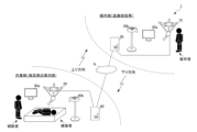
- FIG. 1 is a schematic diagram showing the overall configuration of a remote medical support system 1 according to an embodiment of the present invention.
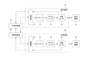
- 1 is a block diagram showing the hardware configuration of an operation device 10 and a working device 20.
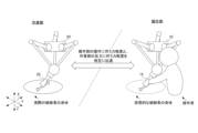
- FIG. 1 is a perspective view showing a configuration example of an operating device 10 and a working device 20.
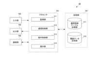
- FIG. A block diagram showing a hardware configuration 700 which is an example of the hardware configuration of the main control unit 30 and the sub-control unit 40.
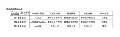
- a block diagram showing the functional configuration of the main control device 30. 1 is a table illustrating an example of a data structure of a communication control table.
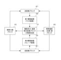
- 13 is a block diagram showing a control algorithm of an operation control unit 313.
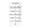
- 11 is a flowchart illustrating the flow of an operation control process executed by the remote medical support system 1.
- 1 is a flowchart illustrating a flow of a remote medical support process executed by the remote medical support system 1.
- the devices on both the operation side and the work side are connected so that they can communicate with each other.
- This communication may be either wired or wireless, and there are no limitations on the communication method.
- the main control device 30 and the sub-control device 40 can also communicate with each other remotely via a network N.
- this network N is a public network such as the Internet, and is not a bandwidth-guaranteed network in which a certain communication speed is guaranteed, but rather a best-effort network in which a certain communication speed is not guaranteed.
- the 1 also illustrates an operator on the operating side, and an assistant and a subject on the working side.
- the operator performs a medical procedure on the subject by remotely operating the operating device 10 to operate the working device 20.
- the operator is, for example, a specialist or an ultrasound technician certified by the Japan Society of Ultrasonics who has experience in this medical procedure.
- the assistant is, for example, a non-specialist medical staff member such as a family doctor or an emergency team who has little experience in this medical procedure.
- the subject is a person who is suffering from (or suspected of having) a disease or is injured, and who undergoes this medical procedure and is the subject for whom the operator makes a diagnosis.
- the subject may also be a person who requires regular checkups and follow-up, such as a pregnant woman or a person suffering from a chronic disease.
- the assistant requests the operator to perform a medical procedure on the subject.
- the operator remotely performs a medical procedure on the subject.
- the operating device 10 operates as a master device to drive a mechanism that accepts operations from an operator.
- the working device 20 operates as a slave device to drive a mechanism that executes a medical procedure including palpation on a subject.
- a medical procedure including palpation on a subject includes all medical procedures such as non-invasive palpation.
- the working device 20 directly or indirectly contacts the subject via another attached member or the like to realize such a medical procedure including palpation on a subject. Note that when the working device 20 performs such a medical procedure including palpation, a medical procedure not including palpation may or may not be performed.
- the main control device 30 performs control (bilateral control) to transmit haptics between the mechanism driven by the operating device 10 and the mechanism driven by the working device 20.
- control bilateral control
- the operation of the operator on the operating device 10 is transmitted to the mechanism driven by the working device 20
- the reaction force (position and force response) from the working device 20 is transmitted to the mechanism driven by the operating device 10 as haptics.
- the displays 30a and 40a each have a function of displaying an image and a function as a speaker, while the cameras 30b and 40b each have a function of capturing an image and a function as a microphone. Images and sounds of the operating side captured and collected by the camera 40b, or measurement results measured by medical procedures, etc. are played on the display 30a on the operating side via the network N. Similarly, images and sounds of the operating side captured and collected by the camera 30b, or measurement results measured by medical procedures, etc. are played on the display 40a on the operating side via the network N.
- the remote medical support system 1 enables medical professionals who perform diagnoses remotely to make diagnoses from various perspectives (e.g., palpation, percussion, visual inspection, and auscultation). Therefore, according to the remote medical support system 1, it is possible to solve the problem of more appropriately supporting a diagnosis when a diagnosis involving a medical procedure is performed remotely.
- the above is an outline of this embodiment.
- FIG. 2 is a block diagram showing the hardware configuration of the operation device 10 and the working device 20.
- the operating device 10 includes an actuator 12 for driving an operating mechanism 15, a driver 11 for driving the actuator 12, and a position sensor 13 for detecting the position of a movable part of the operating mechanism 15 that is moved by being driven by the actuator 12.
- the operating device 10 also includes a communication unit 14 for communicating between the driver 11 and the position sensor 13 and the main control device 30, and the operating mechanism 15.
- the working device 20 also includes an actuator 22 for driving the working mechanism 25, a driver 21 for driving the actuator 22, and a position sensor 23 for detecting the position of a movable part of the working mechanism 25 that is moved by being driven by the actuator 22.
- the working device 20 also includes a communication unit 24 for communication between the driver 21 and the position sensor 23 and the sub-controller 40, and the working mechanism 25.
- the position of the movable part of the operation mechanism 15 detected by the position sensor 13 is, for example, the position of a predetermined part of the movable part of the operation mechanism 15.
- the position of a predetermined part of the operator who operates the operation mechanism 15 may be used.
- the position of the movable part of the working mechanism 25 detected by the position sensor 23 is, for example, the position of a predetermined part of the movable part of the working mechanism 25.
- the position of a predetermined part where the working mechanism 25 comes into contact with the subject for example, the position of the tip of the working mechanism 25
- the position of a predetermined part where the working mechanism 25 comes into contact with the subject for example, the position of the tip of the working mechanism 25
- the rotation angle of the output shaft of each actuator may be detected by a rotary encoder built into each actuator. That is, in this embodiment, the concept of position includes an angle (for example, the rotation angle of the output shaft of the actuator, etc.), and information related to position includes position, angle, speed, angular velocity, acceleration, and angular acceleration.
- position and speed (or acceleration) or angle and angular velocity (or angular acceleration) are parameters that can be replaced by differential and integral calculations, when processing related to position or angle, it is possible to replace them with speed or angular velocity, etc. as appropriate before processing.
- only one system of each driver, each actuator, and each position sensor is illustrated in the operation device 10 and the working device 20, but multiple systems of these can be provided depending on the number of operation mechanisms 15 and working mechanisms 25 and the number of each actuator.
- the main control device 30 realizes bilateral control that transmits haptic sensations between the operation mechanism 15 of the operating device 10, which is the master device, and the working mechanism 25 of the working device 20, which is the slave device, by outputting control commands to the driver 11 and the driver 21 based on the positions detected by the position sensors 13 and 23.
- the sub-control device 40 plays a role in relaying the positions detected by the position sensors 23 and the control commands output by the main control device 30 to the driver 21.
- a specific algorithm for realizing control for transmitting this haptic sensation (bilateral control) will be described later with reference to FIG.
- FIG. 3 is a perspective view showing an example configuration of the operation device 10 and the working device 20.
- the shapes and structures of the operation device 10 and the working device 20 are not particularly limited, but in this embodiment, as an example, it is assumed that the operation device 10 and the working device 20 have the same shape and structure, and only the functions of the operation mechanism 15 and the working mechanism 25 are different. Note that in FIG. 3, the hardware configuration shown in FIG. 2 (here, drivers 11, 21, actuators 12, 22, position sensors 13, 23, and communication units 14, 24) is not shown.
- the operating device 10 and the working device 20 are realized as devices having a link mechanism including multiple (here, three) link shafts that connect the base and the end effector in order to perform a specified task with the end effector.
- this link mechanism has a three-axis structure that can move in the X direction on a horizontal plane, the Y direction perpendicular to the X direction on the horizontal plane, and the Z direction (i.e., the vertical direction) perpendicular to both the X and Y directions, and can move the end effector three-dimensionally by driving actuators 12, 22 realized by servo motors, air cylinders, etc.
- the bases of the operating device 10 and the working device 20 are fixed to the ceiling or wall of the operating side or working side, or to a workbench, etc.
- an operating mechanism 15 is attached to the tip of the operating device 10 as an end effector.
- this operating mechanism 15 is a dummy device configured in a shape that imitates an ultrasonic probe.
- This operating mechanism 15 does not need to have the function of an ultrasonic probe, and does not need to have components such as an acoustic lens or a transducer inside.
- it is desirable that the surface texture and weight are similar to those of an actual ultrasonic probe so that remote operation can be performed with the same feeling as when using an actual ultrasonic probe.
- a working mechanism 25 is attached to the tip of the working device 20 as an end effector.
- this working mechanism 25 is an ultrasound probe that is commonly used in medical settings.
- the working mechanism 25 is moved in a predetermined direction while in contact with the subject's body, and is able to receive reflected ultrasound waves and generate image data based on this (hereinafter referred to as an "ultrasound image").
- the ultrasound image is played back on the working side display 30a, and the operator can refer to this ultrasound image to observe the condition of the subject's organs and fetus.
- the configuration shown in FIG. 3 is merely an example.
- the operation device 10 and the working device 20 may have different structures, may be a serial link mechanism instead of a parallel link mechanism, and the number of axes is not limited. For example, they may be six axes with a higher degree of freedom, or two axes that can be realized with a simpler configuration.
- the operation device 10 may be a multi-fingered device worn by the operator, and the working device 20 may be a robot manipulator that contacts the subject.
- the operation device 10 and the working device 20 may be realized as a configuration specific to this embodiment, or may be realized as a general-purpose robot arm or the like.
- the operation mechanism 15 and the working device 20, which are end effectors are not limited to an ultrasonic probe, and may be other medical devices and dummy devices configured to imitate the medical devices.
- various medical devices may be detachable, and different medical devices (and dummy devices configured to imitate the medical devices) may be replaced as end effectors depending on the situation.
- FIG. 4 is a block diagram showing a hardware configuration 700, which is an example of the hardware configuration of the main control device 30 and the sub-control device 40.
- the hardware configuration 700 includes a processor 701, a ROM (Read Only Memory) 702, a RAM (Random Access Memory) 703, a bus 704, an input unit 705, an output unit 706, a storage unit 707, a communication unit 708, and a drive 709.
- ROM Read Only Memory
- RAM Random Access Memory
- the processor 701 executes various processes according to a program recorded in the ROM 702 or a program loaded from the storage unit 707 to the RAM 703 .
- the RAM 703 also stores data and the like necessary for the processor 701 to execute various processes.
- the processor 701, ROM 702, and RAM 703 are interconnected via a bus 704.
- An input unit 705, an output unit 706, a memory unit 707, a communication unit 708, and a drive 709 are connected to the bus 704.
- the input unit 705 includes input devices such as a mouse and keyboard, and accepts input of various information to the main control unit 30 and the sub-control unit 40.
- the input unit 705 of the main control unit 30 also accepts input of images and sounds of the operating side captured and collected by the camera 30b.
- the input unit 705 of the sub-controller 40 also accepts input of images and sounds of the working side captured and collected by the camera 40b, as well as measurement results of the working mechanism 25 (e.g., an ultrasound image showing the measurement results).
- the output unit 706 is composed of a display, a speaker, etc., and outputs images and sounds.
- the output unit 706 of the main control device 30 outputs images, sounds, measurement results, etc. of the working side received via the network N from the display 30a.
- the output unit 706 of the sub-control device 40 outputs images, sounds, measurement results, etc. of the operating side received via the network N from the display 40a.
- the storage unit 707 is configured with a hard disk or a dynamic random access memory (DRAM) or the like, and stores various data managed by each server.
- the communication unit 708 controls communications with other devices via the network.
- Removable media 750 such as a magnetic disk, an optical disk, a magneto-optical disk, or a semiconductor memory, is appropriately loaded into the drive 709.
- a program read from the removable media 750 by the drive 709 is installed in the storage unit 707 as necessary.
- the above hardware configuration is the basic configuration of the main control unit 30 and the sub-control unit 40, and it is possible to have a configuration that does not include some of the hardware, to have additional hardware, or to change the hardware implementation form.
- the main control unit 30 and the sub-control unit 40 having such a hardware configuration cooperate to perform "motion control processing" and "remote medical support processing.”
- the operation control process is a series of processes that control the operation of each mechanism by performing control (bilateral control) to transmit haptic sensation between the operation mechanism 15 driven by the operating device 10 and the working mechanism 25 driven by the working device 20.
- the remote medical support process is a series of processes that utilize the motion control process to support the operator in remote operation in remote medical care.
- the motion control process is realized as a subroutine of the remote medical support process.
- FIG. 5 is a block diagram showing the functional configuration of main control device 30.
- a monitor unit 311, a communication control unit 312, an operation control unit 313, and a presentation unit 314 function in the processor 701, as shown in Fig. 5.
- a communication control table storage unit 371 and a history data storage unit 372 are formed in the storage unit 707. Including cases not specifically mentioned below, data required to realize processing is transmitted and received between these functional blocks at appropriate times as appropriate.
- the monitoring unit 311 monitors the communication quality of the communication path used by the main control unit 30 and the sub-control unit 40 to send and receive data.
- the communication path includes the network N, but as described above, this network N is a best-effort type network in which a specified communication speed is not guaranteed. Therefore, the communication quality in the network N is not constant. Therefore, the monitoring unit 311 monitors values indicating the communication quality based on various indicators.
- the monitoring unit 311 transmits segments and receives ACKs between the main control unit 30 and the sub-control unit 40, and monitors the value of the round trip time required for these transmissions and receptions.
- the monitoring unit 311 obtains and monitors the communication delay time from the difference between the time of transmission and the time of reception included in the received data.
- the monitor 311 measures and monitors a packet loss rate value indicating the rate at which packets are lost in the network, or a jitter value indicating fluctuations in network delay.
- the monitoring unit 311 outputs these monitored values to the communication control unit 312 as the monitoring results of the communication quality. Note that which value the communication control unit 312 outputs to the communication control unit 312 as the monitoring result can be set appropriately taking into consideration the characteristics of the network N being used, etc.
- the communication control unit 312 changes the communication mode (so to speak, the communication mode) for transmitting and receiving data according to the communication quality monitored by the monitoring unit 311.
- the criteria for differentiating the communication modes and the specific contents of the communication modes are defined in advance, for example, as a communication control table and stored in the communication control table storage unit 371.
- the communication control table storage unit 371 functions as a storage unit that stores the communication control table.
- FIG. 6 is a table showing an example of the data structure of a communication control table.
- a row is provided for each communication mode.
- each column stores the settings corresponding to each communication mode.
- the communication control unit 312 selects a communication mode according to the communication quality monitored by the monitoring unit 311, and controls the communication between the operation device 10 and the work device 20 via the network N in a manner consistent with the selected communication mode.
- a criterion for selecting the communication mode may be, for example, a comparison between the communication quality monitored by the monitoring unit 311 and a preset threshold value. For example, the value indicating the communication quality monitored by the monitoring unit 311 indicates a higher value as the communication quality is better. In this case, for example, if the monitored value is equal to or greater than the first threshold value ("XX" in the figure), the first communication mode is selected.
- the second communication mode is selected.
- the third communication mode is selected. Note that if the value indicating the communication quality monitored by the monitoring unit 311 is a value that is lower the better the communication quality, the magnitude relationship between the value indicating the communication quality and the threshold value will be the opposite of that described above.
- the first communication mode is assumed to satisfy a predetermined communication quality (i.e., the communication quality is good).
- the first threshold value is set to a value corresponding to a communication quality that is sufficient for transmitting the force haptics in both directions in real time. For example, if the communication delay time is monitored, 20 [ms] is set as the first threshold value, and if the delay time is less than this, the first communication mode is selected. Alternatively, if the random packet loss is monitored, 20 [%] is set as the first threshold value, and if the packet loss is less than this, the first communication mode is selected.
- Such values of 20 [ms] and 20 [%] are merely examples of values that can be set as the first threshold value.
- An arbitrary value can be set as the first threshold value based on various criteria such as the environment in which this embodiment is implemented, the content of the medical procedure actually performed, and the accuracy required by the operator.
- the second communication mode is a state in which communication is possible but does not satisfy a predetermined communication quality.
- the third communication mode is a state in which communication is impossible or extremely difficult.
- the second threshold value can be determined based on this boundary. Note that these threshold values are merely examples, and appropriate values can be set depending on the type of medical procedure performed by remote control, the required accuracy, etc.
- the communication control unit 312 selects the communication mode according to the communication quality monitored by the monitoring unit 311, it controls the communication between the operating device 10 and the working device 20 via the network N in a method defined in the communication control table.
- the first communication mode all of the force-tactile information, visual information, and auditory information are transmitted and received instantly (i.e., in real time) and bidirectionally.
- the force-tactile information is a parameter value used for controlling the transmission of force-tactile sensations (bilateral control) between the operation mechanism 15 driven by the operation device 10 and the working mechanism 25 driven by the working device 20.
- the force-tactile information is a value indicating the position detected by the position sensor 13 or the position sensor 23, or a control command value for the driver 11 or the driver 21 calculated by the main control device 30.
- values indicating, for example, speed, acceleration, force, impedance, etc. may be included in the force-tactile information.
- the visual information includes images of the facial expression of the operator on the operating side, the facial expression of the subject on the performing side, and the target area of the medical procedure, captured by camera 30b or camera 40b, as well as images of measurement results measured by the operating mechanism 25, etc. (e.g., ultrasound images showing the measurement results), and text indicating the patient's attributes (e.g., age, gender, and symptoms) entered by the assistant into the sub-controller 40.
- the auditory information includes the voice of the operator on the operating side, the voice of the subject on the working side, and the measurement results (e.g., the subject's heart sounds indicating the measurement results) collected by the working mechanism 25, etc. At least a part of this visual information and auditory information corresponds to the "support information" of the present invention.
- the ultrasound probe in the case of medical procedures using an ultrasound probe, it is important to make a diagnosis by visually inspecting the ultrasound image measured by the ultrasound probe. To do so, it is necessary to contact the ultrasound probe with the target part of the subject with an appropriate amount of force and move it appropriately (for example, reciprocating in a specified direction). However, it is not easy to make appropriate contact and move it appropriately in this way, and a technique based on the experience of the operator (for example, a doctor) is required. If the ultrasound probe is used in an inappropriate manner, the ultrasound image itself may be inaccurate, which may lead to a misdiagnosis. However, in the first communication mode, the transmission of force-tactile information can assist in the execution of this procedure, and it is also possible to present the ultrasound image, which is visual information, in parallel.
- the operator can make a diagnosis by visually inspecting the ultrasound image while confirming that the procedure is being performed appropriately by touch.
- the operator on the operating side can perform the medical procedure by remote control himself or herself, as if he or she were actually performing the medical procedure face-to-face with the subject.
- the operator may intentionally press the ultrasound probe against the subject, regardless of whether an ultrasound image is being acquired, and make a diagnosis based on the subject's reaction to it. For example, if the subject is in severe pain, a diagnosis may be made based on the possibility of peritonitis.
- the strength of the pressure can be transmitted as a force haptic sensation, and visual information such as the subject's facial expression and auditory information such as the subject's voice, which indicate the subject's reaction at that time, can also be presented, making it possible to make a diagnosis using this method.
- visual and auditory information such as facial expressions and voices of the operator on the operating side and facial expressions and voices of the assistant on the working side may be transmitted and received to enable communication between the operator and the assistant.
- the remote operation itself may be supported by presenting an image of the area of the subject that is the target of the medical procedure or an image of the tip of the working mechanism 25.
- the second communication mode In the case of the second communication mode, all of this force-tactile information, visual information, and auditory information is accumulated in the working device 20 in chronological order. In other words, the acquired information itself (raw data) is not transmitted one by one, but is accumulated and made into a data file. This data file is then transmitted collectively. Note that in the second communication mode, taking into consideration communication quality, data files are transmitted from the working side to the operating side, but transmission from the operating side to the working side is canceled. In other words, it is a one-way communication.
- the operating device 20 is operated on a predetermined trajectory, and the haptic information, visual information, and audio information obtained thereby are transmitted to the operating side.
- the operator can accurately feel each piece of information obtained on the operating side, and can make a diagnosis based on this information, although the transmission of each piece of information, such as haptic information, is not in real time but asynchronous, and there is a slight delay in the transmission of each piece of information, such as haptic information.
- the diagnosis may be further supported by having the operator, assistant, and subject communicate with each other via a smartphone or the like using a mobile phone network.
- Operating the operating device 20 on a predetermined trajectory may be realized, for example, by storing haptic information for realizing the operation in the sub-control device 40 in advance and outputting this to the operating device 20.
- it may be realized by having the assistant directly operate the operating device 20 in response to instructions from the operator, etc.
- the assistant may, for example, attempt to move to a location with a better communication environment or attempt to transport the patient to a nearby medical facility.
- the force-tactile information and visual information acquired by the working device 20 may be analyzed by the working sub-control device 40 using statistical methods, machine learning, etc., to perform analysis for diagnosis without relying on the assistant.
- a statistical method means, for example, making a rule-based diagnosis based on statistical information such as haptic and visual information accumulated in the past for various subjects.
- machine learning means, for example, constructing a learning model in advance that takes past statistical information such as that described above as input and outputs the diagnosis results at that time.
- a diagnosis can be made by inputting information about the subject currently being diagnosed into this learning model. In other words, even if communication is interrupted and the device is in a stand-alone state, it can support the operator or assistant.
- the monitoring of communication quality by the monitoring unit 311 and the selection of the communication mode by the communication control unit 312 have been described above. These processes may be performed only at the beginning of the remote medical support process, or may be performed periodically thereafter, taking into consideration fluctuations in communication quality.
- the communication mode may be manually selected according to the operation of the operator or assistant. For example, if the first communication mode is selected, but the communication quality deteriorates and the operator feels uncomfortable with the remote operation, the operator may manually switch to the second communication mode, etc. Alternatively, if a compatible operator is not found, the third communication mode may be selected, and then, if a compatible operator is found, the assistant may manually switch to the first communication mode, etc.
- the settings relating to the communication mode are managed in a table format called a communication control table, they may be managed in other data formats.
- the operation control unit 313 controls the transmission of haptic sensation between the operation mechanism 15 driven by the operating device 10 and the working mechanism 25 driven by the working device 20, thereby controlling the operation of each mechanism.
- the communication control unit 312 acquires haptic information for achieving the control.
- the communication control unit 312 acquires the positions (specifically, positions or angles) of movable parts of each mechanism that are moved by driving the actuators 12, 22 from the position sensors 13, 23.
- the physical quantity data such as positions acquired by the communication control unit 312 is used as reference values for the operation of each mechanism driven by the operating device 10 or the working device 20 in the haptic transmission algorithm.
- FIG. 7 is a block diagram showing a control algorithm of the operation control unit 313.
- the algorithm implemented in the operation control unit 313 is expressed as a control law including a functional force/speed allocation conversion block FT, an ideal force source block FC, an ideal speed (position) source block PC, and an inverse conversion block IFT.
- the control algorithm shown in Fig. 7 is described in a patent publication (Japanese Patent No. 6382203) owned by Keio University, which constitutes the applicant of the present application, and various control algorithms described in the patent publication can be used as appropriate in this embodiment.
- the master device in the controlled system CS is constituted by the operation device 10
- the slave device is constituted by the working device 20.
- the functional force/speed allocation conversion block FT is a block that defines the conversion of control energy into the range of speed (position) and force that is set according to the function of the controlled system CS. Specifically, the functional force/speed allocation conversion block FT defines a coordinate conversion that takes as input the value (reference value) that serves as the reference for the function of the controlled system CS and the current position (or current angle) of the movable part of each mechanism that is moved by the actuators 12, 22.
- This coordinate conversion generally converts an input vector whose elements are the reference value and the current position (current angle) into an output vector consisting of a position (angle) for calculating a control target value for position (angle), and also converts an input vector whose elements are the reference value and the current force into an output vector consisting of a force for calculating a control target value for force.
- the individual variables (variables in real space) of the movable parts of each mechanism moved by the actuators 12 and 22 are "converted" into a group of variables of the entire system expressing the force haptic transmission function (variables in space after coordinate transformation), and control energy is assigned to the control energy of position (angle) and the control energy of force.
- the coordinate transformation set in the functional force/speed allocation conversion block FT converts the coordinates of real space (oblique coordinates) in which position (angle) and force are related to each other into coordinates of virtual space (orthogonal coordinates) in which position (angle) and force are independent of each other.
- the state value in the space after coordinate transformation can be calculated under the condition that the difference in position (angle) is zero and the sum of forces is zero (equal forces are output in opposite directions) between the input of the positions (angles) of the movable parts of each mechanism moved by driving the actuator 12 and the force calculated from these positions (angles) and the reference value serving as the basis for controlling the position (angle) and force.
- the reference value serving as the basis for controlling the position (angle) and force is the position (angle) of the movable parts of each mechanism moved by driving the actuator 22 in the working device 20 and the force calculated from these positions (angles).
- the state value in the space after coordinate transformation can be calculated under the condition that the difference in position (angle) is zero and the sum of forces is zero (equal forces are output in opposite directions) between the input of the positions (angles) of the movable parts of each mechanism moved by driving the actuator 22 and the force calculated from these positions (angles) and the reference value serving as the basis for controlling the position (angle) and force.
- the reference value serving as the basis for controlling the position (angle) and force is the position (angle) of the movable parts of each mechanism moved by driving the actuator 12 in the operating device 10 and the force calculated from these positions (angles).
- the ideal force source block FC is a block that performs calculations in the force domain according to the coordinate transformation defined by the functional force-speed allocation transformation block FT.
- a target value for force is set when performing calculations based on the coordinate transformation defined by the functional force-speed allocation transformation block FT.
- This target value is set as a fixed value or a variable value depending on the function to be realized. For example, when a function similar to the function indicated by the reference value is to be realized, zero can be set as the target value, and when scaling is performed, a value obtained by enlarging or reducing the information indicating the function indicated by the reference value can be set.
- the ideal force source block FC can set an upper limit value for the force energy determined by calculations in the force domain. By setting an upper limit value for the force energy, for example, the contact force when the working device 20 contacts the subject is limited, and it is possible to prevent the working mechanism 25, etc. from being pressed too hard against the body of the subject.
- the ideal velocity (position) source block PC is a block that performs calculations in the position (angle) domain according to the coordinate transformation defined by the functional force-speed allocation transformation block FT.
- a target value for the position (angle) when performing calculations based on the coordinate transformation defined by the functional force-speed allocation transformation block FT is set.
- This target value is set as a fixed value or a variable value depending on the function to be realized. For example, when a function similar to the function indicated by the reference value is to be realized, zero can be set as the target value, and when scaling is performed, a value obtained by enlarging or reducing the information indicating the function to be reproduced can be set.
- the ideal velocity (position) source block PC can set an upper limit value for the energy of the force determined by calculations in the position (angle) domain. Setting an upper limit value for the energy of the position (angle) limits the distance that the working device 20 can advance and retreat, and can prevent the working mechanism 25, etc. from being pressed too hard against the subject's body.
- the inverse transformation block IFT is a block that inversely transforms values in the position (angle) and force domains into values in the input domain to the controlled system CS (e.g., voltage values or current values, etc.) (i.e., determines command values in real space).
- the main controller 30 receives as input the time-series position (angle) detection values detected by the position sensors 13, 23. These time-series position (angle) detection values represent the operations of the actuators 12, 22, and the main controller 30 applies coordinate transformation for transmitting haptics to the input positions (angles) and forces derived from these positions (angles).
- the presentation unit 314 presents to the operator various pieces of information that the communication control unit 312 has acquired from the worker side through communication via the network N. Presentation is achieved, for example, by playing visual and auditory information on the display 30a via the output unit 706. Playing this information to the worker can assist the worker in making a diagnosis.
- the history data storage unit 372 stores various information acquired by the communication control unit 312 as history data.
- the history data stored by the history data storage unit 372 can be used as a log associated with medical procedures. For example, it can be used to analyze the success or failure of a medical procedure and the time required for the medical procedure. Alternatively, it can be used as teaching materials for teaching remote operation procedures to operators with little experience in remote medical procedures.
- FIG. 8 is a block diagram showing the functional configuration of the sub-control device 40.
- a communication control unit 411 When the above-mentioned operation control process or remote medical support process is performed, a communication control unit 411, a data accumulation unit 412, an analysis unit 413, and a presentation unit 414 function in the processor 701, as shown in Fig. 8.
- a communication control table storage unit 471 and a history data storage unit 472 are formed in the storage unit 707. Including cases not specifically mentioned below, data required to realize processing is transmitted and received between these functional blocks at appropriate times as appropriate.
- the communication control unit 411 corresponds to the communication control unit 312 of the main control unit 30.
- the communication control unit 411 is notified of the communication mode to be selected by the communication control unit 312 of the main control unit 30.
- This communication mode to be selected is the same communication mode as the communication mode selected by the communication control unit 312 of the main control unit 30.
- the communication control unit 411 selects a communication mode in response to this, it transmits and receives haptic information, visual information, and auditory information to and from the communication control unit 312 of the main control unit 30 in accordance with the contents specified in the communication control table stored in the communication control table storage unit 471. However, as described above, depending on the communication mode, transmission and reception of this information is not performed.
- the communication control table storage unit 471 functions as a storage unit that stores the communication control table.
- the communication control table stored in the communication control table storage unit 471 is the same as the communication control table stored in the communication control table storage unit 371.
- the data accumulation unit 412 functions when the second communication mode is selected, and accumulates all of the haptic, visual, and auditory information to be transmitted in chronological order in the working device 20. That is, the acquired information itself (raw data) is accumulated as a data file. In this case, the data accumulation unit 412 may accumulate the information by using the storage area of the RAM 703, or may accumulate the information by using the storage area of the storage unit 707. The communication control unit 411 then transmits this data file collectively at periodic timing or the like. This allows the operator to feel each piece of information obtained on the working side, although not in real time and with some time error, and allows diagnosis to be made based on this information.
- the analysis unit 413 functions when the third communication mode is selected, and analyzes the force-tactile information and visual information acquired by the working device 20 using statistical methods, machine learning, etc. This allows analysis for diagnosis to be performed without relying on an assistant.
- the specific contents of the statistical methods, machine learning, etc. used to perform the analysis are as described above.
- the presentation unit 414 presents various pieces of information acquired by the data storage unit 412 from the operating side through communication via the network N to the assistant and the subject.
- the presentation unit 414 also presents the analysis results by the analysis unit 413 to the assistant and the subject. Presentation is achieved, for example, by playing visual and auditory information on the display 40a via the output unit 706. Playing this information to the assistant and the subject can support them.
- the history data storage unit 472 stores, as history data, various types of information acquired by the data accumulation unit 412.
- the history data stored in the history data storage unit 472 is similar to the history data stored in the history data storage unit 372 of the main control device 30 in that it can be utilized as a log associated with medical procedures. Next, the details of each process performed by the remote medical support system 1 will be described.
- [Operation Control Processing] 9 is a flowchart illustrating the flow of the operation control process executed by the remote medical support system 1.
- the operation control process is executed as a subroutine in the remote medical support process.
- step S1 the operation control unit 313 acquires the position (angle) of the movable part of the mechanism to be moved by the actuator.
- the mechanisms to be moved are the operation mechanism 15 and the working mechanism 25.
- the operation control unit 313 acquires the positions corresponding to these mechanisms from the position sensor 13 and the position sensor 23 via the communication control unit 312.
- step S2 the motion control unit 313 converts an input vector in the real space into a vector in the virtual space.
- step S3 the motion control unit 313 executes calculations in the domain of velocity (position) and calculations in the domain of force.
- step S4 the motion control unit 313 inversely converts the values in the domains of velocity (position) and force into values in the domain of input to the controlled system CS (vectors in real space).
- step S5 the operation control unit 313 outputs command values for the actuators 12 and 22. This ends the process. However, as long as the first communication mode is being performed, the process is performed continuously. In other words, in practice, as long as the first communication mode is being performed, steps S1 to S5 of the process are repeated.
- each mechanism can be controlled by performing control (bilateral control) to transmit haptic sensations between the operation mechanism 15 driven by the operation device 10 and the working mechanism 25 driven by the working device 20.
- Remote medical support processing 10 is a flowchart illustrating the flow of the remote medical support processing executed by the remote medical support system 1.
- the remote medical support processing is executed when the operation device 10 or the main control device 30 receives an instruction to start the remote medical support processing from a user such as an operator or an assistant.
- step S11 the monitoring unit 311 monitors the communication quality of the communication path used by the main control unit 30 and the sub-control unit 40 to transmit and receive data.
- step S ⁇ b>12 the communication control unit 312 selects a communication mode depending on the communication quality monitored by the monitoring unit 311 .
- step S13 the communication control unit 312 determines which communication mode is selected. If the selected communication mode is the first communication mode, it is determined to be the "first communication mode" in step S13, and the process proceeds to step S14. If the selected communication mode is the second communication mode, it is determined to be the "second communication mode” in step S13, and the process proceeds to step S17. If the selected communication mode is the third communication mode, it is determined to be the "third communication mode" in step S13, and the process proceeds to step S20.
- step S14 the communication control unit 312 and the communication control unit 411, which has been notified that the first communication mode has been selected, transmit and receive all haptic information, visual information, and auditory information in chronological order, instantly, and bidirectionally.
- step S15 the operation control unit 313 executes the above-mentioned operation control process as a subroutine. Note that this operation control process is repeatedly executed while the first communication mode is being performed.
- step S16 the presentation unit 314 and the presentation unit 414 present various types of information such as visual information and audio information.
- step S17 the data storage unit 412 stores all of the force-tactile information, visual information, and audio information to be transmitted in chronological order in the working device 20 to create a data file.
- step S18 the communication control unit 411 transmits the accumulated data files all at once.
- step S19 the presentation unit 314 presents various types of information such as visual information and audio information. In this case, the force-tactile sensation may be transmitted to the operator via the operation mechanism 15 based on the force-tactile information received by the operation control unit 313.
- step S20 the analysis unit 413 analyzes the force-tactile information and visual information acquired by the working device 20 using a statistical method, machine learning, or the like.
- step S21 the presentation unit 414 presents the analysis results obtained by the analysis unit 413 to the assistant and the subject.
- step S22 the communication control unit 312 determines whether or not a manual operation for switching the communication mode has been accepted. If a manual operation for switching the communication mode has been accepted, the result of step S22 is determined as Yes, and the process proceeds to step S23. On the other hand, if a manual operation for switching the communication mode has not been accepted, the result of step S22 is determined as No, and the process proceeds to step S24.
- step S23 the communication control unit 312 selects a communication mode in response to the received switching operation. After that, the process returns to step S13, and the process based on the selected communication mode continues.
- step S24 the monitoring unit 311 determines whether or not to monitor the communication quality again.
- the monitoring unit 311 monitors the communication quality again, for example, when a predetermined time has passed since the previous monitoring, or when an operation to instruct monitoring again has been received from the operator or assistant. If the communication quality is to be monitored again, the determination in step S24 is Yes, and the process returns to step S11, and the process is repeated from monitoring the communication quality again. On the other hand, if the communication quality is not to be monitored again, the determination in step S24 is No, and the process proceeds to step S25.
- step S25 the communications control unit 312 determines whether or not to end this process. For example, this process ends on the condition that an operation to end this process is received from the operator or assistant. If this process is to end, step S25 determines Yes, and this process ends. On the other hand, if this process is not to end, step S determines No, the process returns to step S13, and processing continues based on the selected communication mode.
- the remote medical support process described above can utilize the motion control process to assist the operator in remote operation during remote medical support work.
- the operation mechanism 25 is controlled in response to the remote operation received by the operation mechanism 15, and the reaction force applied to the operation mechanism 25 in response to the contact of the operation mechanism 25 with the subject is transmitted to the operator via the operation mechanism 15 as a haptic sensation. That is, control for transmitting haptic sensation between the operation mechanism 15 and the operation mechanism 25 (i.e., bilateral control) can be performed.
- control for transmitting haptic sensation between the operation mechanism 15 and the operation mechanism 25 i.e., bilateral control
- This allows the operator to perform a medical procedure for diagnosis based on haptic sensation as if he or she were performing a medical procedure directly facing the subject.
- the presentation unit 314 presents the operator with support information acquired by the operation mechanism for supporting a diagnosis based on a medical procedure.
- the operator can perform a medical procedure for diagnosis based on other senses (e.g., vision and hearing) other than haptic sensation.
- the remote medical support system 1 enables medical professionals who perform diagnoses remotely to make diagnoses from a variety of perspectives (e.g., palpation, percussion, visual examination, and auscultation). Therefore, according to the remote medical support system 1, when a diagnosis involving a medical procedure is performed remotely, it is possible to more appropriately support the diagnosis.
- the present invention can be applied, for example, to cases where the operating side and the working side are in different prefectures in the country, or where they are in the country and overseas.
- the operating side and the working side may correspond to each other in a one-to-one relationship, but may also correspond to each other in a one-to-many relationship, so that one operator can perform diagnoses involving medical procedures on multiple subjects in parallel or at different times.
- the present invention is not limited to this, and more communication modes may be provided in stages.
- the first communication mode is further divided into stages, and when the communication quality is good, the force haptics is transmitted so that the upper limit of performance that can be realized by the control algorithm of the operation control unit 313 can be exhibited.
- the operation of the working device 20 is suppressed (i.e., the transmission of the force haptics is suppressed) to stabilize the operation.
- the force or speed of the working device 20 may be limited or the operation of the working device 20 may be forcibly stopped so that the working device 20 does not perform an unexpected operation.
- the first and second communication modes may be further divided, and when the communication quality deteriorates, the force-haptic information may be transmitted in real time to reduce the amount of communication, but the visual and auditory information may be transmitted as data files with a delay.
- the analysis unit 413 may perform an analysis and present the analysis results to the operator to assist the operator in making a diagnosis.
- a functional block similar to the analysis unit 413 may be provided in the main control device 30 on the operating side so that analysis may also be performed on the operating side.
- the operation device 10 and the main control device 30 are realized as separate devices.
- the present invention is not limited to this, and for example, the operation device 10 and the main control device 30 may be realized as an integrated device and installed on the operation side.
- the work device 20 and the main control device 30 may be realized as an integrated device and installed on the work side.
- the control of the transmission of haptics may be distributed between the operating device 10 and the working device 20.
- a function block for operation control is added to each device.
- the function block for operation control of each device acquires detection values from its own sensor and detection values from sensors of the other device, and outputs command values to the driver of its own device based on a control algorithm similar to that of the main control device 30 described above. In this manner, the transmission of haptics between the other device and the operating device may be realized.
- the above-mentioned modified examples 1 to 3 can also be appropriately combined to form a separate modified example.
- the remote medical support system 1 includes the working mechanism 25 , the operation mechanism 15 , the motion control unit 313 , and the presentation unit 314 .
- the working mechanism 25 is a mechanism for performing medical procedures, including palpation, on a subject.
- the operation mechanism 15 is a mechanism that receives remote operation of the working mechanism 25 from an operator.
- the operation control unit 313 controls the operation of the working mechanism 25 in response to the remote operation received by the operating mechanism 15, and transmits the reaction force applied to the working mechanism 25 in response to the working mechanism 25 coming into contact with the subject to the operator via the operating mechanism 15 as a force haptic sensation.
- the presentation unit 314 presents to the operator assistance information that is acquired by the operating mechanism and that supports diagnosis based on medical practice.
- the operation mechanism 25 is controlled in response to the remote operation received by the operation mechanism 15, and the reaction force applied to the operation mechanism 25 in response to the contact of the operation mechanism 25 with the subject is transmitted to the operator via the operation mechanism 15 as a haptic sensation. That is, control for transmitting haptic sensation between the operation mechanism 15 and the operation mechanism 25 (i.e., bilateral control) can be performed.
- control for transmitting haptic sensation between the operation mechanism 15 and the operation mechanism 25 i.e., bilateral control
- This allows the operator to perform a medical procedure for diagnosis based on haptic sensation as if he or she were performing a medical procedure directly facing the subject.
- the presentation unit 314 presents the operator with support information acquired by the operation mechanism for supporting a diagnosis based on a medical procedure.
- the operator can perform a medical procedure for diagnosis based on other senses (e.g., vision and hearing) other than haptic sensation.
- the remote medical support system 1 enables medical professionals who perform diagnoses remotely to make diagnoses from a variety of perspectives (e.g., palpation, percussion, visual examination, and auscultation). Therefore, according to the remote medical support system 1, when a diagnosis involving a medical procedure is performed remotely, it is possible to more appropriately support the diagnosis.
- the remote medical support system 1 further includes a monitoring unit 311 and a communication control unit 312 .
- the monitoring unit 311 monitors the communication quality of the communication path used by the operation control unit 313 and the presentation unit 314 to transmit and receive data.
- the communication control unit 312 changes the manner in which data is transmitted and received depending on the communication quality monitored by the monitoring unit 311 . This makes it possible to transmit and receive data in a manner appropriate to the communication quality even in various environments where the communication quality is not constant.
- the communication control unit 312 When the communication quality monitored by the monitoring unit 311 satisfies a predetermined communication quality, data is transmitted and received in real time in a time series manner; If the communication quality monitored by the monitoring unit 311 does not satisfy a predetermined communication quality, data is accumulated in chronological order, and the accumulated data is then transmitted and received collectively. This allows data to be transmitted and received using the most appropriate means depending on the communication quality.
- the remote medical support system 1 further includes a presentation unit 414 .
- the presentation unit 414 performs an analysis regarding a diagnosis based on medical treatment based on either or both of the reaction force and support information applied to the working mechanism 25, and presents the analysis results to the working mechanism. This makes it possible to support a user (e.g., an assistant) on the working mechanism side even in a situation where it is difficult to execute communication.
- the operation control unit 313 is When the communication quality monitored by the monitoring unit 311 does not satisfy a predetermined communication quality, the operation of the working mechanism 25 corresponding to the remote operation accepted by the operation mechanism 15 is suppressed. This makes it possible to suppress the influence of communication quality and prevent the operating mechanism 25 from performing unexpected operations.
- the working mechanism 25 is equipped with measuring equipment for measuring the condition of the subject,
- the support information includes at least information indicating the measurement results obtained by the measuring device. This allows the operator performing remote operation to not only obtain the measurement results of the measuring device, but also to recognize whether the measuring device is being remotely operated so as to perform measurements appropriately.
- the operation control unit 313 is Instead of remote operation received by the operating mechanism 15 from an operator, the operation of the working mechanism 25 is controlled in response to operation received directly from another operator, and the reaction force given to the working mechanism 25 in response to the working mechanism 25 coming into contact with the subject is transmitted to the operator via the operating mechanism 15 as a force haptic sensation. This allows the operator to make a diagnosis based on the haptic sensation felt when actually touching the subject, even in cases where remote operation is difficult.
- the function of executing the series of processes according to the above-mentioned embodiment can be realized by hardware, software, or a combination of these. In other words, it is sufficient that the function of executing the series of processes described above is realized in any one of the remote medical support systems 1, and there is no particular limitation on how this function is realized.
- the processor that executes this arithmetic processing includes not only processors that are composed of various types of processing devices alone, such as single processors, multiprocessors, and multicore processors, but also processors that combine these types of processing devices with processing circuits such as ASICs (Application Specific Integrated Circuits) or FPGAs (Field-Programmable Gate Arrays).
- ASICs Application Specific Integrated Circuits
- FPGAs Field-Programmable Gate Arrays
- the program constituting the software is installed on a computer via a network or a recording medium.
- the computer may be a computer with dedicated hardware built in, or a general-purpose computer (e.g., a general-purpose electronic device such as a general-purpose personal computer) that can execute a specified function by installing a program.
- the steps of writing the program may include only processes that are performed chronologically according to the order, but may also include processes that are executed in parallel or individually.
- the steps of writing the program may be executed in any order as long as they do not deviate from the gist of the present invention.
- a recording medium on which such a program is recorded may be provided to the user by being distributed separately from the computer main body, or may be provided to the user in a state in which it is already installed in the computer main body.
- the storage medium distributed separately from the computer main body is, for example, removable media 750, and is composed of a magnetic disk (including a floppy disk), an optical disk, or a magneto-optical disk.
- the optical disk is, for example, a CD-ROM (Compact Disc-Read Only Memory), a DVD (Digital Versatile Disc), or a Blu-ray (registered trademark) Disc.
- the magneto-optical disk is, for example, an MD (Mini Disc).
- the recording medium provided to the user in a state where it is already installed in the computer main body is, for example, a storage unit 707 on which the program is recorded, and is composed of a HDD (hard disk drive) or SSD (solid state drive).
Landscapes
- Health & Medical Sciences (AREA)
- Engineering & Computer Science (AREA)
- Life Sciences & Earth Sciences (AREA)
- Biomedical Technology (AREA)
- Medical Informatics (AREA)
- Mechanical Engineering (AREA)
- Biophysics (AREA)
- Pathology (AREA)
- Robotics (AREA)
- Heart & Thoracic Surgery (AREA)
- Physics & Mathematics (AREA)
- Molecular Biology (AREA)
- Surgery (AREA)
- Animal Behavior & Ethology (AREA)
- General Health & Medical Sciences (AREA)
- Public Health (AREA)
- Veterinary Medicine (AREA)
- Manipulator (AREA)
- Measuring And Recording Apparatus For Diagnosis (AREA)
Abstract
【課題】遠隔から医療行為を伴う診断を行う場合に、より適切に診断を支援する。 【解決手段】遠隔医療支援システム1は、作業機構25と、操作機構15と、動作制御部313と、提示部314と、を備える。作業機構25は、被検者への触診を含む医療行為を行うための機構である。操作機構15は、作業機構25に対する遠隔操作を操作者から受け付ける機構である。動作制御部313は、操作機構15が受け付けた遠隔操作に応じて、作業機構25の動作を制御すると共に、作業機構25が被検者へ接触したことに応じて作業機構25に与えられた反力を、操作機構15を介して操作者に力触覚として伝達する。提示部314は、作業機構側で取得された、医療行為に基づく診断を支援する支援情報を、操作者に提示する。
Description
本発明は、遠隔医療支援システム、遠隔医療支援方法、及びプログラムに関する。
医療の現場において、罹患の疑いのある被検者は、自ら医療施設に赴いて、医師等の医療従事者の診断を受けることが通常である。この場合、医師等の医療従事者は、触診、打診、視診、及び聴診といった多様な観点から被検者を診断する。
しかしながら、医療施設の混雑状況等の事情によっては即時に診断を受けられない場合もある。また、緊急搬送中に診断を受ける場合や、在宅医療で診断を受ける場合、あるいは緊急時のトリアージを行う場合等において、経験を積んだ医療従事者の診断をその場で受けるのは、困難なことが実情である。
例えば、超音波(US:Ultrasonography)を用いた医療機器による診断を適切に行うには、医療従事者の経験等に依るところもあり、このような経験者が常時現場に配置され、いつでも診断できるということは医療従事者の人的リソース等を考慮すると現実的ではない。
しかしながら、医療施設の混雑状況等の事情によっては即時に診断を受けられない場合もある。また、緊急搬送中に診断を受ける場合や、在宅医療で診断を受ける場合、あるいは緊急時のトリアージを行う場合等において、経験を積んだ医療従事者の診断をその場で受けるのは、困難なことが実情である。
例えば、超音波(US:Ultrasonography)を用いた医療機器による診断を適切に行うには、医療従事者の経験等に依るところもあり、このような経験者が常時現場に配置され、いつでも診断できるということは医療従事者の人的リソース等を考慮すると現実的ではない。
このような状況を考慮して、遠隔操作により医療行為を支援するという技術の一例が特許文献1に開示されている。特許文献1に開示の技術では、操作者によって過剰な速度での操作が行われた場合であっても、遠隔操作対象のロボットアームの挙動は過剰な速度にはならないよう制御することで、医療従事者の作業を支援するとされている。
しかしながら、医療行為は、高い作業精度が要求される作業である。そのため、特許文献1に開示の技術のように、単にロボットアームの挙動が過剰な速度とならないように制御するのみでは、要求される作業精度を満たすことは困難と考えられる。
すなわち、医療従事者が、遠隔から、例えば、触診、打診、視診、及び聴診といった様々な観点での診断を行うためには、未だ改善の余地があると言える。
すなわち、医療従事者が、遠隔から、例えば、触診、打診、視診、及び聴診といった様々な観点での診断を行うためには、未だ改善の余地があると言える。
本発明は、このような状況に鑑みてなされたものである。そして、本発明の課題は、遠隔から医療行為を伴う診断を行う場合に、より適切に診断を支援することである。
上記課題を解決するため、本発明の一実施形態に係る遠隔医療支援システムは、
被検者への触診を含む医療行為を行うための作業機構と、
前記作業機構に対する遠隔操作を操作者から受け付ける操作機構と、
前記操作機構が受け付けた遠隔操作に応じて、前記作業機構の動作を制御すると共に、前記作業機構が前記被検者へ接触したことに応じて前記作業機構に与えられた反力を、前記操作機構を介して前記操作者に力触覚として伝達する動作制御手段と、
前記作業機構側で取得された、前記医療行為に基づく診断を支援する支援情報を、前記操作者に提示する支援情報提示手段と、
を備えることを特徴とする。
被検者への触診を含む医療行為を行うための作業機構と、
前記作業機構に対する遠隔操作を操作者から受け付ける操作機構と、
前記操作機構が受け付けた遠隔操作に応じて、前記作業機構の動作を制御すると共に、前記作業機構が前記被検者へ接触したことに応じて前記作業機構に与えられた反力を、前記操作機構を介して前記操作者に力触覚として伝達する動作制御手段と、
前記作業機構側で取得された、前記医療行為に基づく診断を支援する支援情報を、前記操作者に提示する支援情報提示手段と、
を備えることを特徴とする。
本発明によれば、遠隔から医療行為を伴う診断を行う場合に、より適切に診断を支援することができる。
以下、添付の図面を参照して本発明の実施形態の一例について説明する。
[システム構成]
図1は、本実施形態に係る遠隔医療支援システム1の全体構成を示す模式図である。図1に示すように、遠隔医療支援システム1は、例えば、病院等の医療施設等である「操作側」と、緊急搬送中の救急車の車内等である「作業側」に分散して設置される。
具体的に、操作側において、遠隔医療支援システム1は、操作装置10、主制御装置30、ディスプレイ30a、及びカメラ30bを含む。一方で、作業側において、遠隔医療支援システム1は、作業装置20、副制御装置40、ディスプレイ40a、及びカメラ40bを含む。
図1は、本実施形態に係る遠隔医療支援システム1の全体構成を示す模式図である。図1に示すように、遠隔医療支援システム1は、例えば、病院等の医療施設等である「操作側」と、緊急搬送中の救急車の車内等である「作業側」に分散して設置される。
具体的に、操作側において、遠隔医療支援システム1は、操作装置10、主制御装置30、ディスプレイ30a、及びカメラ30bを含む。一方で、作業側において、遠隔医療支援システム1は、作業装置20、副制御装置40、ディスプレイ40a、及びカメラ40bを含む。
また、操作側と、作業側のそれぞれにおいて各装置は相互に通信可能に接続される。この通信は、有線あるいは無線の何れであってもよいし、通信方式についても限定されない。加えて、主制御装置30と副制御装置40は、ネットワークNを介して相互に遠隔通信を行うことも可能である。ただし、このネットワークNは、インターネット等の公衆網であり、所定の通信速度が保証された帯域保証型のネットワークではなく、所定の通信速度が保証されないベストエフォート(best effort)型のネットワークである。
また図1には、操作側に操作者を図示すると共に、作業側に補助者及び被検者を図示する。操作者は、操作装置10を遠隔操作して作業装置20を動作させることにより、被検者に対する医療行為を行う。この操作者は、例えば、この医療行為についての経験を積んだ、専門医や日本超音波学会公認の超音波検査士等である。また、補助者は、例えば、この医療行為についての経験が浅い、かかりつけ医や救急隊等の専門外の医療スタッフである。さらに、被検者は、疾病に罹患している(あるいは罹患の疑いがある)、又は怪我をしている人物であって、この医療行為を受けることで、操作者が診断を下す対象となる人物である。なお、被検者は、例えば、妊婦や慢性疾患の罹患者のように、定期的な検診や経過観察が必要な人物であってもよい。
本実施形態では、「上り方向」として図示するように、補助者が、操作者に対して被検者のへの医療行為の実行を依頼する。また、「下り方向」として図示するように、この依頼に応じて、操作者は、遠隔操作により被検者への医療行為を実行する。
このような遠隔医療支援システム1において、操作装置10は、マスタ装置として動作することにより、操作者からの操作を受け付ける機構を駆動する。一方で、作業装置20は、スレーブ装置として動作することにより、被検者への触診を含む医療行為を実行する機構を駆動する。ここで、被検者への触診を含む医療行為とは、非侵襲的な触診等の医療行為全般を含むものである。例えば、作業装置20が、直接的にあるいは装着された他の部材等を介して間接的に被験者に接触することで、このような被検者への触診を含む医療行為が実現される。なお、作業装置20により、このような触診を含む医療行為が行われる際に、触診を含まない医療行為がさらに行われてもよいし、行われなくてもよい。
この場合に、主制御装置30は、操作装置10が駆動する機構と、作業装置20が駆動する機構との間で、力触覚を伝達する制御(バイラテラル制御)を行う。これにより、操作装置10に対する操作者の操作(位置と力の入力)が、作業装置20が駆動する機構に伝達されると共に、作業装置20からの反力(位置と力の応答)が、操作装置10が駆動する機構に力触覚として伝達される。
この場合に、主制御装置30は、操作装置10が駆動する機構と、作業装置20が駆動する機構との間で、力触覚を伝達する制御(バイラテラル制御)を行う。これにより、操作装置10に対する操作者の操作(位置と力の入力)が、作業装置20が駆動する機構に伝達されると共に、作業装置20からの反力(位置と力の応答)が、操作装置10が駆動する機構に力触覚として伝達される。
また、ディスプレイ30a及びディスプレイ40aは、画像を表示する機能と、スピーカとしての機能を含んでいる。また、カメラ30b及びカメラ40bは、画像を撮像する機能と、マイクとしての機能を含んでいる。
そして、カメラ40bにより撮像及び集音された作業側の画像や音、あるいは、医療行為により測定された測定結果等は、ネットワークNを介して操作側のディスプレイ30aから再生される。また同様にして、カメラ30bにより撮像及び集音された操作側の画像や音、あるいは、医療行為により測定された測定結果等は、ネットワークNを介して操作側のディスプレイ40aから再生される。
そして、カメラ40bにより撮像及び集音された作業側の画像や音、あるいは、医療行為により測定された測定結果等は、ネットワークNを介して操作側のディスプレイ30aから再生される。また同様にして、カメラ30bにより撮像及び集音された操作側の画像や音、あるいは、医療行為により測定された測定結果等は、ネットワークNを介して操作側のディスプレイ40aから再生される。
これにより、操作者は、伝達される力触覚以外に加えて、他の感覚(例えば、視覚や聴覚)にも基づいて、診断のための医療行為を行うことができる。つまり、遠隔医療支援システム1は、遠隔から診断を行う医療従事者に対して、多様な観点(例えば、触診、打診、視診、及び聴診)からの診断を可能としている。
従って、遠隔医療支援システム1によれば、遠隔から医療行為を伴う診断を行う場合に、より適切に診断を支援する、という課題を解決することができる。
以上が、本実施形態の概略である。
従って、遠隔医療支援システム1によれば、遠隔から医療行為を伴う診断を行う場合に、より適切に診断を支援する、という課題を解決することができる。
以上が、本実施形態の概略である。
[装置構成]
次に、遠隔医療支援システム1に含まれる各装置の構成について説明する。
図2は、操作装置10と、作業装置20のハードウェア構成を示すブロック図である。
図2に示すように、操作装置10は、操作機構15を駆動するためのアクチュエータ12と、アクチュエータ12を駆動するドライバ11と、アクチュエータ12による駆動で移動される操作機構15の可動部の位置を検出する位置センサ13と、を備えている。また、操作装置10は、これらドライバ11や、位置センサ13が、主制御装置30との間で通信を行うための通信部14と、操作機構15も備えている。
次に、遠隔医療支援システム1に含まれる各装置の構成について説明する。
図2は、操作装置10と、作業装置20のハードウェア構成を示すブロック図である。
図2に示すように、操作装置10は、操作機構15を駆動するためのアクチュエータ12と、アクチュエータ12を駆動するドライバ11と、アクチュエータ12による駆動で移動される操作機構15の可動部の位置を検出する位置センサ13と、を備えている。また、操作装置10は、これらドライバ11や、位置センサ13が、主制御装置30との間で通信を行うための通信部14と、操作機構15も備えている。
一方で、作業装置20も同様に、作業機構25を駆動するためのアクチュエータ22と、アクチュエータ22を駆動するドライバ21と、アクチュエータ22による駆動で移動される作業機構25の可動部の位置を検出する位置センサ23と、を備えている。作業装置20は、ドライバ21や、位置センサ23が、副制御装置40との間で通信を行うための通信部24と、作業機構25も備えている。
この場合に、位置センサ13が検出する操作機構15の可動部の位置とは、例えば、操作機構15の可動部の所定の部位の位置である。ただし、操作機構15の可動部の位置に代えて、操作機構15を操作する操作者の所定の部位の位置を用いることとしてもよい。
また、位置センサ23が検出する作業機構25の可動部の位置とは、例えば、作業機構25の可動部の所定の部位の位置である。ただし、作業機構25の可動部の位置に代えて、作業機構25が被検者に接触する所定の部位の位置(例えば、作業機構25の先端部の位置)を用いることとしてもよい。
また、位置センサ23が検出する作業機構25の可動部の位置とは、例えば、作業機構25の可動部の所定の部位の位置である。ただし、作業機構25の可動部の位置に代えて、作業機構25が被検者に接触する所定の部位の位置(例えば、作業機構25の先端部の位置)を用いることとしてもよい。
また、本実施形態では、これら操作機構15の可動部の位置や、作業機構25の可動部の位置に代えて、各アクチュエータの出力軸の回転角度を各アクチュエータに内蔵されたロータリーエンコーダによって検出することとしてもよい。すなわち、本実施形態において、位置の概念には角度(例えば、アクチュエータの出力軸の回転角度等)が含まれるものとし、位置に関する情報には、位置、角度、速度、角速度、加速度及び角加速度が含まれるものとする。また、位置と速度(又は加速度)あるいは角度と角速度(又は角加速度)は、微積分演算により置換可能なパラメータであるため、位置あるいは角度に関する処理を行う場合、適宜、速度あるいは角速度等に置換してから処理を行うことが可能である。また、図中では、操作装置10や作業装置20において、各ドライバ、各アクチュエータ、及び各位置センサを一系統のみ図示しているが、操作機構15や作業機構25の数や、それぞれのアクチュエータの数に応じて、これらを複数系統設けることができる。
このような構成において、主制御装置30は、位置センサ13や位置センサ23が検出した位置に基づいて、ドライバ11やドライバ21に対して制御指令を出力することにより、マスタ装置である操作装置10の操作機構15と、スレーブ装置である作業装置20の作業機構25との間で力触覚を伝達するバイラテラル制御を実現する。なお、この場合に副制御装置40は、位置センサ23が検出した位置や、主制御装置30が出力したドライバ21に対する制御指令を中継する役割を果たす。
なお、この力触覚を伝達する制御(バイラテラル制御)を実現するための具体的なアルゴリズムについては、図7を参照して後述する。
なお、この力触覚を伝達する制御(バイラテラル制御)を実現するための具体的なアルゴリズムについては、図7を参照して後述する。
図3は、操作装置10と、作業装置20の構成例について示す斜視図である。これら操作装置10及び作業装置20において、その形状や構造は特に限定されないが、本実施形態では、一例として、操作装置10及び作業装置20は同等の形状及び構造をしており、操作機構15と作業機構25の機能のみが異なることを想定する。なお、図3では、図2に示したハードウェア構成(ここでは、ドライバ11,21、アクチュエータ12,22、位置センサ13,23、及び通信部14,24)については図示を省略する。
操作装置10及び作業装置20は、エンドエフェクタによって所定の作業を行うために、ベースとエンドエフェクタとを接続する複数(ここでは、3本)のリンクシャフトを含んだリンク機構を有する装置として実現される。図示するように、このリンク機構は、水平面におけるX方向と、水平面においてX方向と直交するY方向と、X方向及びY方向の双方と直交するZ方向(すなわち、鉛直方向)と、に移動可能な3軸の構造であり、サーボモータやエアシリンダ等で実現されるアクチュエータ12,22が駆動することにより、エンドエフェクタを三次元的に移動させることができる。
この場合に、操作装置10及び作業装置20のベースは、操作側や作業側の天井や壁面、あるいは作業台等に固定される。また、操作装置10の先端には、エンドエフェクタとして操作機構15が装着される。本実施形態では、一例として、この操作機構15は、超音波プローブを模した形状に構成されたダミーのデバイスであることを想定する。この操作機構15は、超音波プローブとしての機能を有する必要はなく、例えば、音響レンズや振動子といった構成要素を内部に備えていなくてもよい。ただし、実際に超音波プローブを利用する場合と同様の感覚で遠隔操作を行えるように、表面の質感や重量については、実際の超音波プローブと同様にすることが望ましい。
一方で、作業装置20の先端には、エンドエフェクタとして作業機構25が装着される。本実施形態では、一例として、この作業機構25は、医療現場において通常に用いられる超音波プローブであることを想定する。作業機構25は、被検者の身体に接触した状態で所定方向に動かされることで、反射した超音波を受信し、これに基づいた画像データ(以下、「超音波画像」と称する。)を生成することができる。超音波画像は、作業側のディスプレイ30aにて再生され、操作者は、この超音波画像を参照することで、被検者の臓器や胎児の様子を観察することができる。
なお、図3に示した構成は、あくまで一例である。例えば、操作装置10及び作業装置20は、互いに異なる構造であってもよいし、パラレルリンク機構ではなく、シリアルリンク機構であってもよいし、その軸数も限定されない。例えば、より自由度の高い6軸としたり、より簡易な構成で実現できる2軸としたりしてもよい。また、例えば、手で直接接触して触診を行う場合を想定して、操作者が装着する多指型のデバイスを操作装置10とし、被検者に接触するロボットマニピュレーターを作業装置20としてもよい。また、操作装置10及び作業装置20は、本実施形態特有の構成として実現してもよいが、汎用のロボットアーム等で実現するようにしてもよい。さらに、エンドエフェクタである操作機構15や作業装置20は、超音波プローブにかぎらず、これ以外の医療機器と、その医療機器を模した構成のダミーのデバイスとしてもよい。この場合に、種々の医療機器を脱着可能とし、状況に応じて異なる医療機器(及びその医療機器を模した構成のダミーのデバイス)をエンドエフェクタとして交換可能としてもよい。
図4は、主制御装置30や副制御装置40のハードウェア構成の一例である、ハードウェア構成700を示すブロック図である。
図4に示すように、このハードウェア構成700は、プロセッサ701と、ROM(Read Only Memory)702と、RAM(Random Access Memory)703と、バス704と、入力部705と、出力部706と、記憶部707と、通信部708と、ドライブ709と、を備えている。
図4に示すように、このハードウェア構成700は、プロセッサ701と、ROM(Read Only Memory)702と、RAM(Random Access Memory)703と、バス704と、入力部705と、出力部706と、記憶部707と、通信部708と、ドライブ709と、を備えている。
プロセッサ701は、ROM702に記録されているプログラム、又は、記憶部707からRAM703にロードされたプログラムに従って各種の処理を実行する。
RAM703には、プロセッサ701が各種の処理を実行する上において必要なデータ等も適宜記憶される。
RAM703には、プロセッサ701が各種の処理を実行する上において必要なデータ等も適宜記憶される。
プロセッサ701、ROM702及びRAM703は、バス704を介して相互に接続されている。バス704には、入力部705、出力部706、記憶部707、通信部708及びドライブ709が接続されている。
入力部705は、マウスやキーボード等の入力装置を備え、主制御装置30や副制御装置40に対する各種情報の入力を受け付ける。この場合、主制御装置30の入力部705は、カメラ30bにより撮像及び集音された操作側の画像や音等の入力も受け付ける。一方で、副制御装置40の入力部705は、カメラ40bにより撮像及び集音された作業側の画像や音、さらに作業機構25の測定結果(例えば、測定結果を示す超音波画像)等の入力も受け付ける。
出力部706は、ディスプレイやスピーカ等で構成され、画像や音を出力する。この場合、主制御装置30の出力部706は、ネットワークNを介して受信された作業側の画像や音や測定結果等をディスプレイ30aから出力する。一方で、副制御装置40の出力部706は、ネットワークNを介して受信された操作側の画像や音や測定結果等をディスプレイ40aから出力する。
記憶部707は、ハードディスクあるいはDRAM(Dynamic Random Access Memory)等で構成され、各サーバで管理される各種データを記憶する。
通信部708は、ネットワークを介して他の装置との間で行う通信を制御する。
記憶部707は、ハードディスクあるいはDRAM(Dynamic Random Access Memory)等で構成され、各サーバで管理される各種データを記憶する。
通信部708は、ネットワークを介して他の装置との間で行う通信を制御する。
ドライブ709には、磁気ディスク、光ディスク、光磁気ディスク、あるいは半導体メモリ等よりなる、リムーバブルメディア750が適宜装着される。ドライブ709によってリムーバブルメディア750から読み出されたプログラムは、必要に応じて記憶部707にインストールされる。
なお、上記ハードウェア構成は、主制御装置30や副制御装置40の基本的構成であり、一部のハードウェアを備えない構成としたり、付加的なハードウェアを備えたり、ハードウェアの実装形態を変更したりすることができる。
なお、上記ハードウェア構成は、主制御装置30や副制御装置40の基本的構成であり、一部のハードウェアを備えない構成としたり、付加的なハードウェアを備えたり、ハードウェアの実装形態を変更したりすることができる。
このようなハードウェア構成を有する主制御装置30及び副制御装置40は、協働することによって、「動作制御処理」や、「遠隔医療支援処理」を行う。
ここで、動作制御処理は、操作装置10が駆動する操作機構15と、作業装置20が駆動する作業機構25との間で、力触覚を伝達する制御(バイラテラル制御)を行うことで、各機構の動作を制御する一連の処理である。
また、遠隔医療支援処理は、動作制御処理を利用して、操作者の遠隔医療における遠隔操作を支援する一連の処理である。なお、動作制御処理は、遠隔医療支援処理のサブルーチンとして実現される。
ここで、動作制御処理は、操作装置10が駆動する操作機構15と、作業装置20が駆動する作業機構25との間で、力触覚を伝達する制御(バイラテラル制御)を行うことで、各機構の動作を制御する一連の処理である。
また、遠隔医療支援処理は、動作制御処理を利用して、操作者の遠隔医療における遠隔操作を支援する一連の処理である。なお、動作制御処理は、遠隔医療支援処理のサブルーチンとして実現される。
図5は、主制御装置30の機能的構成を示すブロック図である。
上記の動作制御処理や遠隔医療支援処理が行われる場合、図5に示すように、プロセッサ701において、監視部311と、通信制御部312と、動作制御部313と、提示部314と、が機能する。また、記憶部707には、通信制御テーブル記憶部371と、履歴データ記憶部372と、が形成される。
以下で特に言及しない場合も含め、これら機能ブロック間では、処理を実現するために必要なデータを、適切なタイミングで適宜送受信する。
上記の動作制御処理や遠隔医療支援処理が行われる場合、図5に示すように、プロセッサ701において、監視部311と、通信制御部312と、動作制御部313と、提示部314と、が機能する。また、記憶部707には、通信制御テーブル記憶部371と、履歴データ記憶部372と、が形成される。
以下で特に言及しない場合も含め、これら機能ブロック間では、処理を実現するために必要なデータを、適切なタイミングで適宜送受信する。
監視部311は、主制御装置30と、副制御装置40がデータを送受信するために用いる通信経路の通信品質を監視する。ここで、通信経路にはネットワークNが含まれるが、上述したように、このネットワークNは、所定の通信速度が保証されないベストエフォート型のネットワークである。そのため、ネットワークNにおける通信品質は一定ではない。そこで、監視部311は、様々な指標に基づいて、通信品質を示す値を監視する。
例えば、監視部311は、主制御装置30と副制御装置40との間で、セグメント送信とACK受信を行い、これらの送受信に要したラウンドトリップタイムの値を監視する。他にも、例えば、監視部311は、主制御装置30と副制御装置40との間で、時刻同期のためにデータ送信時の時刻を送信するデータの送信パラメータに含めて通信を行っているような場合には、受信したデータに含まれる送信時の時刻と受信時の時刻との差分から通信遅延時間を求めて監視する。
あるいは、監視部311は、ネットワークでパケットが損失する割合を示すパケット損失率の値や、ネットワーク遅延の揺らぎを示すジッタの値を計測して、監視する。
なお、これらの様々な指標に基づいた、通信品質を示す値の計測方法については、当業者にとってよく知られているので、ここでの詳細な説明は省略する。
あるいは、監視部311は、ネットワークでパケットが損失する割合を示すパケット損失率の値や、ネットワーク遅延の揺らぎを示すジッタの値を計測して、監視する。
なお、これらの様々な指標に基づいた、通信品質を示す値の計測方法については、当業者にとってよく知られているので、ここでの詳細な説明は省略する。
そして、監視部311は、これら監視した値を、通信品質の監視結果として通信制御部312に対して出力する。なお、通信制御部312が何れの値を監視結果として通信制御部312に出力するのかについては、利用するネットワークNの特性等を考慮して、適宜設定しておくことができる。
通信制御部312は、監視部311が監視した通信品質に応じて、データを送受信する通信態様(いわば、通信モード)を異ならせる。これにより、通信品質が一定ではない環境下であっても、その通信品質に応じた、様々な態様でデータを送受信して医療行為を支援することができる。
このように、通信態様を異ならせる基準や、通信態様の具体的な内容については、例えば、通信制御テーブルとして予め規定されており、通信制御テーブル記憶部371に記憶されている。すなわち、通信制御テーブル記憶部371は、通信制御テーブルを記憶する記憶部として機能する。
このように、通信態様を異ならせる基準や、通信態様の具体的な内容については、例えば、通信制御テーブルとして予め規定されており、通信制御テーブル記憶部371に記憶されている。すなわち、通信制御テーブル記憶部371は、通信制御テーブルを記憶する記憶部として機能する。
図6は、通信制御テーブルのデータ構造の一例を示すテーブルである。本テーブルでは、通信態様毎に行が設けられる。また、各列には各通信態様に対応した設定内容が格納される。本実施形態では、一例として第1通信態様~第3通信態様という3つの通信態様が存在することを想定する。ただし、これは一例に過ぎず、より多くの通信態様を段階的に設けてもよいし、通信態様を2つのみとしてもよい。
通信制御部312は、監視部311が監視した通信品質に応じて、通信態様を選択し、選択した通信態様に沿った方法で、ネットワークNを介した操作装置10と作業装置20との通信を実行するように制御する。この場合、通信態様の選択基準としては、例えば、監視部311が監視した通信品質と予め設定した閾値とを比較することが考えられる。例えば、監視部311が監視した通信品質を示す値が、通信品質が良好であるほど高い値を示すものであるとする。この場合、例えば、監視した値が、第1閾値(図中「XX」)以上の値であれば、第1通信態様が選択される。また、例えば、監視した値が、第1閾値(図中「XX」)未満、且つ、第2閾値(図中「YY」)以上の値であれば、第2通信態様が選択される。さらに、例えば、監視した値が、第2閾値(図中「YY」)未満の値であれば、第3通信態様が選択される。なお、監視部311が監視した通信品質を示す値が、通信品質が良好であるほど低い値を示すものである場合には、通信品質を示す値と閾値との大小関係は上記とは逆の関係になる。
本実施形態では、第1通信態様は、予め定められた通信品質を満たしている場合であること(すなわち、通信品質が良好なこと)を想定している。また、第1通信態様では、リアルタイムで双方向に力触覚の伝達を行う。そこで、第1閾値は、このようなリアルタイムで双方向に力触覚の伝達を行うことが十分な通信品質に対応した値とする。例えば、監視するのが通信遅延時間であれば、20[ms]を第1閾値として、これ未満の遅延時間であれば第1通信態様を選択するようにする。あるいは、監視するのがランダムなパケットロスであれば、20[%]を第1閾値として、これ未満のパケットロスであれば第1通信態様を選択するようにする。なお、このような20[ms]や20[%]という値は、第1閾値として設定できる値の一例に過ぎない。本実施形態を実装する環境や、実際に行われる医療行為の内容や、操作者が要求する精度といった各種の基準に基づいて、任意の値を第1閾値として設定することができる。
また、第2通信態様は、通信可能な状態であるが予め定められた通信品質を満たしていない場合である。さらに、第3通信態様は、通信が不可能な状態、あるいは通信が極めて困難な状態である。そこで、第2閾値は、この境界を基準にして決定することができる。なお、これらの閾値は、あくまで例示に過ぎず、遠隔操作により行われる医療行為の種類や、要求される精度等に応じて、適切な値を設定することが可能である。
通信制御部312は、このようにして、監視部311が監視した通信品質に応じて、通信態様を選択すると、通信制御テーブルに規定されている方法で、ネットワークNを介した操作装置10と作業装置20との通信を実行するように制御する。この場合、図示するように、第1通信態様であれば、力触覚情報、視覚情報、及び聴覚情報の全てを即時(すなわち、リアルタイム)、且つ、双方向で送受信する。
通信制御部312は、このようにして、監視部311が監視した通信品質に応じて、通信態様を選択すると、通信制御テーブルに規定されている方法で、ネットワークNを介した操作装置10と作業装置20との通信を実行するように制御する。この場合、図示するように、第1通信態様であれば、力触覚情報、視覚情報、及び聴覚情報の全てを即時(すなわち、リアルタイム)、且つ、双方向で送受信する。
ここで、力触覚情報は、操作装置10が駆動する操作機構15と、作業装置20が駆動する作業機構25との間で、力触覚を伝達する制御(バイラテラル制御)を行うために用いられるパラメータの値である。例えば、力触覚情報は、位置センサ13や位置センサ23が検出した位置を示す値や、主制御装置30が算出したドライバ11やドライバ21に対する制御指令値である。他にも、例えば、速度、加速度、力、インピーダンス等を示す値を力触覚情報に含ませるようにしてもよい。
また、視覚情報は、カメラ30bやカメラ40bにより撮影された、操作側の操作者の表情や、作業側の被検者の表情や医療行為の対象部位の画像や、作業機構25等で測定した測定結果(例えば、測定結果を示す超音波画像)等の画像や、補助者が副制御装置40に入力した患者の属性(例えば、年齢や性別や症状)を示すテキスト等の情報である。
さらに、聴覚情報は、カメラ30bやカメラ40bにより集音された、操作側の操作者の音声や、作業側の被検者の音声や、作業機構25等で測定した測定結果(例えば、測定結果を示す被検者の心音)等である。なお、この視覚情報や聴覚情報の少なくとも一部は、本発明の「支援情報」に相当する。
また、視覚情報は、カメラ30bやカメラ40bにより撮影された、操作側の操作者の表情や、作業側の被検者の表情や医療行為の対象部位の画像や、作業機構25等で測定した測定結果(例えば、測定結果を示す超音波画像)等の画像や、補助者が副制御装置40に入力した患者の属性(例えば、年齢や性別や症状)を示すテキスト等の情報である。
さらに、聴覚情報は、カメラ30bやカメラ40bにより集音された、操作側の操作者の音声や、作業側の被検者の音声や、作業機構25等で測定した測定結果(例えば、測定結果を示す被検者の心音)等である。なお、この視覚情報や聴覚情報の少なくとも一部は、本発明の「支援情報」に相当する。
第1通信態様の場合、これらの力触覚情報、視覚情報、及び聴覚情報の全てを時系列で、即時、且つ、双方向に送受信するので、例えば、これらの提示を受けた操作者は、遠隔操作に基づいた、実際の患者からの反力を力触覚として触覚で感じることができる。また、これと共に、並行して、各種の視覚情報や聴覚情報を、視覚や聴覚で感じることができる。これにより、本実施形態では、遠隔から診断を行う操作者に対して、多様な観点(例えば、触診、打診、視診、及び聴診)からの診断を可能としている。
例えば、超音波プローブを用いた医療行為の場合、超音波プローブにより測定された超音波画像を視覚で目視することで、診断を行うことが重要となる。そのためには、前提として、超音波プローブを被検者の対象部位に適切な力加減で接触させ、適切に移動(例えば、所定の方向への往復運動)させる必要がある。しかしながら、このように適切に接触させて適切に移動させることは容易ではなく、操作者(例えば、医師)の経験に基づいた手技が必要となる。そして、仮に不適切な方法で、超音波プローブを用いた場合には、そもそも超音波画像そのものが不正確なものとなり、誤診につながるおそれがある。しかしながら、第1通信態様では、力触覚情報の伝達により、この手技を実行することを支援できると共に、並行して視覚情報である超音波画像も提示することが可能となる。そのため、操作者は、触覚により適切に手技が実行できていることを確認しながら、視覚により超音波画像を目視して診断を行うことができる。すなわち、仮に作業側に経験の浅い補助者しかいない場合であっても、操作側の操作者は自身で遠隔操作を行うことで、あたかも実際に被検者に対面して医療行為を行っているのと同じ状態で、医療行為を実行することが可能となる。
また、操作者は、超音波画像の取得とは関わりなく、超音波プローブを意図的に押し当てて、それに対する被検者の反応に基づいて、診断を行う場合もある。例えば、被検者が激しい痛みを感じている場合には、腹膜炎のおそれがある等の方法で診断を行う場合である。本実施形態では、押し当てた強さを力触覚として伝達できると共に、その際の被検者の反応を示す、被検者の表情といった視覚情報や、被検者の音声といった聴覚情報も提示できるので、このような方法での診断を行うことも可能となる。
他にも、例えば、視覚情報や聴覚情報として、操作側の操作者の表情や音声と、作業側の補助者の表情や音声を送受信することで、操作者と補助者とのコミュニケーションをとるようにしてもよい。また、例えば、被検者の医療行為の対象部位の画像や作業機構25の先端の画像等を提示することで、遠隔操作を行うこと自体を支援するようにしてもよい。
第2通信態様の場合、これらの力触覚情報、視覚情報、及び聴覚情報の全てを時系列で作業装置20に蓄積する。すなわち、取得したこれらの情報そのもの(生データ)を逐次送信するのではなく、これらを蓄積してデータファイルとする。そして、このデータファイルをまとめて送信する。なお、第2通信態様では、通信品質を考慮して、作業側から操作側へのデータファイルの送信を行うが、操作側から作業側への送信は取りやめる。すなわち、片方向通信とする。
この場合、例えば、作業装置20を予め定められた軌道で動作させ、これにより得られた力触覚情報や、視覚情報や聴覚情報を、操作側に送信する。これにより、操作者は、リアルタイムではなく、時間が非同期となり力触覚情報等の各情報の伝達に多少の遅延が生じるものの、作業側で得られた各情報を的確に感じることができ、これらの情報に基づいて診断を行うことができる。これに加えて、例えば、携帯電話網を利用してスマートフォン等で、操作者と、補助者や被検者がコミュニケーションをとることで、さらに診断を支援するようにしてもよい。作業装置20を予め定められた軌道で動作させることは、例えば、その動作を実現するための力触覚情報を予め副制御装置40に記憶させておき、これを作業装置20に対して出力することで実現するようにしてもよい。あるいは、補助者が操作者の指示等に応じて、作業装置20を直接操作することで、実現するようにしてもよい。
第3通信態様の場合、これらの力触覚情報、視覚情報、及び聴覚情報の全てについて送受信を取り止める。この場合、補助者は、例えば、より通信環境が良好な場所に移動を試みたり、近隣の医療施設に患者を搬送することを試みたりする。また、これに加えて、作業装置20にて取得した力触覚情報や視覚情報を、作業側の副制御装置40にて統計的な手法や機械学習等によって解析することで、補助者に依存することなく診断のための解析を行うようにしてもよい。
この場合、統計的な手法とは、例えば、過去に様々な被検者を対象として蓄積した力触覚情報や視覚情報といった統計的な情報に基づいて決定された、ルールベースで診断をするというものである。また、この場合、機械学習とは、例えば、上記のような過去の統計的な情報を入力とし、その際の診断結果を出力とした学習モデルを予め構築しておくというものである。この学習モデルに、現在診断対象としている被検者の情報を入力することで、診断をすることができる。すなわち、通信途絶して、スタンドアローンとなった状態であっても、操作者や補助者を支援することができる。
以上、監視部311による通信品質の監視や、通信制御部312による通信態様の選択について説明をした。なお、これらの処理は、遠隔医療支援処理を実行する当初に行うだけでもよいし、その後に、通信品質が変動することも考慮して周期的に行うようにしてもよい。また、通信品質に基づいて自動的に通信態様を選択するのみならず、操作者や補助者の操作に応じて、手動で通信態様を選択するようにしてもよい。例えば、第1通信態様を選択していたが、通信品質が悪化してきて、操作者が遠隔操作に違和感を覚えた場合には、操作者が手動で第2通信態様等に切り替えるようにしてもよい。あるいは、対応可能な操作者が見つからない場合には第3通信態様とし、その後、対応可能な操作者が見つかった場合に、補助者が手動で第1通信態様等に切り替えるようにしてもよい。
また、通信態様に関する設定内容ついて、通信制御テーブルというテーブル形式で管理していたが、他のデータ形式で管理するようにしてもよい。
また、通信態様に関する設定内容ついて、通信制御テーブルというテーブル形式で管理していたが、他のデータ形式で管理するようにしてもよい。
このように、本実施形態によれば、通信品質が一定ではない様々な環境下であっても、その通信品質に応じた態様で、医療行為を伴う診断を支援することができる。
図5に戻り、動作制御部313は、操作装置10が駆動する操作機構15と、作業装置20が駆動する作業機構25との間で力触覚を伝達する制御を行うことで、各機構の動作を制御する。
この制御を実現するために、第1通信態様等において通信制御部312は、制御を実現するための力触覚情報を取得する。例えば、通信制御部312は、位置センサ13,23からアクチュエータ12,22による駆動で移動される各機構の可動部の位置(具体的には、位置又は角度)を取得する。通信制御部312によって取得された位置等の物理量データは、力触覚伝達のアルゴリズムにおいて、操作装置10や作業装置20が駆動する各機構の動作の基準値として用いられる。
この制御を実現するために、第1通信態様等において通信制御部312は、制御を実現するための力触覚情報を取得する。例えば、通信制御部312は、位置センサ13,23からアクチュエータ12,22による駆動で移動される各機構の可動部の位置(具体的には、位置又は角度)を取得する。通信制御部312によって取得された位置等の物理量データは、力触覚伝達のアルゴリズムにおいて、操作装置10や作業装置20が駆動する各機構の動作の基準値として用いられる。
図7は、動作制御部313の制御アルゴリズムを示すブロック図である。
図7に示すように、動作制御部313に実装されるアルゴリズムは、機能別力・速度割当変換ブロックFTと、理想力源ブロックFCと、理想速度(位置)源ブロックPCと、逆変換ブロックIFTとを含む制御則として表される。図7に示す制御アルゴリズムは、本願の出願人を構成する慶應義塾が保有する特許権の特許公報(特許第6382203号公報)に記載されているものであり、当該特許公報に記載された各種制御アルゴリズムは、本実施形態においても適宜利用することができる。なお、本実施形態において、制御対象システムCSにおける、マスタ装置は操作装置10によって構成され、スレーブ装置は作業装置20によって構成される。
図7に示すように、動作制御部313に実装されるアルゴリズムは、機能別力・速度割当変換ブロックFTと、理想力源ブロックFCと、理想速度(位置)源ブロックPCと、逆変換ブロックIFTとを含む制御則として表される。図7に示す制御アルゴリズムは、本願の出願人を構成する慶應義塾が保有する特許権の特許公報(特許第6382203号公報)に記載されているものであり、当該特許公報に記載された各種制御アルゴリズムは、本実施形態においても適宜利用することができる。なお、本実施形態において、制御対象システムCSにおける、マスタ装置は操作装置10によって構成され、スレーブ装置は作業装置20によって構成される。
機能別力・速度割当変換ブロックFTは、制御対象システムCSの機能に応じて設定される速度(位置)及び力の領域への制御エネルギーの変換を定義するブロックである。具体的には、機能別力・速度割当変換ブロックFTでは、制御対象システムCSの機能の基準となる値(基準値)と、アクチュエータ12,22による駆動で移動される各機構の可動部の現在位置(又は現在角度)とを入力とする座標変換が定義されている。この座標変換は、一般に、基準値及び現在位置(現在角度)を要素とする入力ベクトルを位置(角度)の制御目標値を算出するための位置(角度)からなる出力ベクトルに変換すると共に、基準値及び現在の力を要素とする入力ベクトルを力の制御目標値を算出するための力からなる出力ベクトルに変換するものである。
機能別力・速度割当変換ブロックFTにおける座標変換を、力触覚の伝達機能を表す内容に設定することにより、操作装置10と作業装置20との間における力触覚の伝達機能を実現したり、力触覚を伝達する動作を、操作装置10を用いることなく作業装置20で再現したりすることができる。また、機能別力・速度割当変換ブロックFTにおける座標変換において、変換行列の要素に係数を設定することにより、位置(角度)あるいは力のスケーリングを行ったりすることができる。
すなわち、本実施形態においては、機能別力・速度割当変換ブロックFTにおいて、アクチュエータ12,22による駆動で移動される各機構の可動部の単体の変数(実空間上の変数)を、力触覚伝達機能を表現するシステム全体の変数群(座標変換後の空間上の変数)に“変換”し、位置(角度)の制御エネルギーと力の制御エネルギーとに制御エネルギーを割り当てる。すなわち、機能別力・速度割当変換ブロックFTに設定される座標変換は、位置(角度)と力とが互いに関連する実空間の座標(斜交座標)を位置(角度)と力とが互いに独立した仮想空間の座標(直交座標)に変換するものである。そのため、アクチュエータ12,22による駆動で移動される各機構の可動部の単体の変数(実空間上の変数)のまま制御を行う場合と比較して、位置(角度)の制御エネルギーと力の制御エネルギーとを独立に与えること、すなわち、位置(角度)と力とを独立に制御することが可能となっている。
本実施形態においては、例えば、操作装置10が出力する位置(角度)及び力を制御する場合、アクチュエータ12による駆動で移動される各機構の可動部の位置(角度)及びこれらの位置(角度)から算出される力の入力と、位置(角度)及び力の制御の基準となる基準値とにおいて、位置(角度)の差がゼロ、力の和がゼロ(逆向きに等しい力が出力される)となることを条件として、座標変換後の空間における状態値の演算を行うことができる。ただし、位置(角度)及び力の制御の基準となる基準値は、作業装置20におけるアクチュエータ22による駆動で移動される各機構の可動部の位置(角度)及びこれらの位置(角度)から算出される力である。
同様に、本実施形態において、例えば、作業装置20が出力する位置(角度)及び力を制御する場合、アクチュエータ22による駆動で移動される各機構の可動部の位置(角度)及びこれらの位置(角度)から算出される力の入力と、位置(角度)及び力の制御の基準となる基準値とにおいて、位置(角度)の差がゼロ、力の和がゼロ(逆向きに等しい力が出力される)となることを条件として、座標変換後の空間における状態値の演算を行うことができる。ただし、位置(角度)及び力の制御の基準となる基準値は、操作装置10におけるアクチュエータ12による駆動で移動される各機構の可動部の位置(角度)及びこれらの位置(角度)から算出される力である。
理想力源ブロックFCは、機能別力・速度割当変換ブロックFTによって定義された座標変換に従って、力の領域における演算を行うブロックである。理想力源ブロックFCにおいては、機能別力・速度割当変換ブロックFTによって定義された座標変換に基づく演算を行う際の力に関する目標値が設定されている。この目標値は、実現される機能に応じて固定値又は可変値として設定される。例えば、基準値が示す機能と同様の機能を実現する場合には、目標値としてゼロを設定したり、スケーリングを行う場合には、基準値が示す機能を表す情報を拡大・縮小した値を設定したりできる。また、理想力源ブロックFCは、力の領域における演算によって決定される力のエネルギーに対し、上限値を設定することができる。力のエネルギーの上限値を設定することで、例えば、作業装置20が、被検者に対して接触する際の接触力の制限を与えることとなり、作業機構25等が被検者の身体に過度に強く押し当てられることを抑制できる。
理想速度(位置)源ブロックPCは、機能別力・速度割当変換ブロックFTによって定義された座標変換に従って、位置(角度)の領域における演算を行うブロックである。理想速度(位置)源ブロックPCにおいては、機能別力・速度割当変換ブロックFTによって定義された座標変換に基づく演算を行う際の位置(角度)に関する目標値が設定されている。この目標値は、実現される機能に応じて固定値又は可変値として設定される。例えば、基準値が示す機能と同様の機能を実現する場合には、目標値としてゼロを設定したり、スケーリングを行う場合には、再現する機能を示す情報を拡大・縮小した値を設定したりできる。また、理想速度(位置)源ブロックPCは、位置(角度)の領域における演算によって決定される力のエネルギーに対し、上限値を設定することができる。位置(角度)のエネルギーの上限値を設定することは、作業装置20が進退する距離の制限を与えることとなり、作業機構25等が被検者の身体に過度に強く押し当てられることを抑制できる。
逆変換ブロックIFTは、位置(角度)及び力の領域の値を制御対象システムCSへの入力の領域の値(例えば、電圧値又は電流値等)に逆変換する(すなわち、実空間の指令値を決定する)ブロックである。
このような制御アルゴリズムの下、主制御装置30には、位置センサ13,23によって検出された時系列の位置(角度)の検出値が入力される。この時系列の位置(角度)の検出値は、アクチュエータ12,22の動作を表すものであり、主制御装置30は、入力された位置(角度)及びこれらの位置(角度)から導出された力に対して、力触覚を伝達する座標変換を適用する。
このような制御アルゴリズムの下、主制御装置30には、位置センサ13,23によって検出された時系列の位置(角度)の検出値が入力される。この時系列の位置(角度)の検出値は、アクチュエータ12,22の動作を表すものであり、主制御装置30は、入力された位置(角度)及びこれらの位置(角度)から導出された力に対して、力触覚を伝達する座標変換を適用する。
図5に戻り、提示部314は、通信制御部312が作業側からネットワークNを介した通信で取得した各種情報を操作者に対して提示する。提示は、例えば、視覚情報や聴覚情報を、出力部706を介してディスプレイ30aから再生させることで実現される。作業者に対して、これら情報を再生することで、作業者の診断を支援することができる。
履歴データ記憶部372は、通信制御部312が取得した各種情報等を履歴データとして記憶する。履歴データ記憶部372が記憶した履歴データは、医療行為に伴うログとして活用することができる。例えば、医療行為の成否や医療行為に要した時間を解析するために活用することができる。あるいは、遠隔操作による医療行為の経験が少ない操作者等に、遠隔操作の手順を教えるための教材等として活用することができる。
図8は、副制御装置40の機能的構成を示すブロック図である。
上記の動作制御処理や遠隔医療支援処理が行われる場合、図8に示すように、プロセッサ701において、通信制御部411と、データ蓄積部412と、解析部413と、提示部414と、が機能する。また、記憶部707には、通信制御テーブル記憶部471と、履歴データ記憶部472と、が形成される。
以下で特に言及しない場合も含め、これら機能ブロック間では、処理を実現するために必要なデータを、適切なタイミングで適宜送受信する。
上記の動作制御処理や遠隔医療支援処理が行われる場合、図8に示すように、プロセッサ701において、通信制御部411と、データ蓄積部412と、解析部413と、提示部414と、が機能する。また、記憶部707には、通信制御テーブル記憶部471と、履歴データ記憶部472と、が形成される。
以下で特に言及しない場合も含め、これら機能ブロック間では、処理を実現するために必要なデータを、適切なタイミングで適宜送受信する。
通信制御部411は、主制御装置30の通信制御部312に相当する部分である。通信制御部411は、主制御装置30の通信制御部312から選択すべき通信態様を通知される。この選択すべき通信態様は、主制御装置30の通信制御部312が選択した通信態様と同一の通信態様である。また、通信制御部411は、これに応じて通信態様を選択すると、通信制御テーブル記憶部471が記憶する通信制御テーブルに規定された内容で、主制御装置30の通信制御部312との間で力触覚情報や視覚情報や聴覚情報を送受信する。ただし、上述したように、通信態様によっては、これら情報の送受信は行われない。
通信制御テーブル記憶部471は、通信制御テーブルを記憶する記憶部として機能する。通信制御テーブル記憶部471が記憶する通信制御テーブルは、通信制御テーブル記憶部371が記憶する通信制御テーブルと同一のものである。
データ蓄積部412は、第2通信態様が選択された場合に機能し、送信すべき力触覚情報、視覚情報、及び聴覚情報の全てを時系列で作業装置20に蓄積する。すなわち、取得したこれらの情報そのもの(生データ)を蓄積してデータファイルとする。この場合、データ蓄積部412は、RAM703の記憶領域を利用して蓄積を行ってもよいし、記憶部707の記憶領域を利用して蓄積を行ってもよい。そして、通信制御部411は、周期的なタイミング等でこのデータファイルをまとめて送信する。これにより、操作者は、リアルタイムではなく、時間の誤差はあるものの、作業側で得られた各情報を感じることができ、これらの情報に基づいて診断を行うことができる。
解析部413は、第3通信態様が選択された場合に機能し、作業装置20にて取得した力触覚情報や視覚情報を、統計的な手法や機械学習等によって解析する。これにより、補助者に依存することなく診断のための解析を行うことができる。なお、解析を行うための、統計的な手法や機械学習等の具体的な内容については、上述した通りである。
提示部414は、データ蓄積部412が操作側からネットワークNを介した通信で取得した各種情報を補助者や被検者に対して提示する。また、提示部414は、解析部413による解析結果についても、補助者や被検者に対して提示する。提示は、例えば、視覚情報や聴覚情報を、出力部706を介してディスプレイ40aから再生させることで実現される。補助者や被検者に対して、これら情報を再生することで、補助者や被検者を支援することができる。
履歴データ記憶部472は、データ蓄積部412が取得した各種情報等を履歴データとして記憶する。履歴データ記憶部472が記憶した履歴データは、医療行為に伴うログとして活用することができる点は、主制御装置30の履歴データ記憶部372が記憶した履歴データと同様である。
次に、遠隔医療支援システム1により行われる各処理の処理内容の詳細について説明をする。
次に、遠隔医療支援システム1により行われる各処理の処理内容の詳細について説明をする。
[動作制御処理]
図9は、遠隔医療支援システム1が実行する動作制御処理の流れを説明するフローチャートである。動作制御処理は、遠隔医療支援処理におけるサブルーチンとして実行される。
図9は、遠隔医療支援システム1が実行する動作制御処理の流れを説明するフローチャートである。動作制御処理は、遠隔医療支援処理におけるサブルーチンとして実行される。
ステップS1において、動作制御部313は、アクチュエータによる駆動で移動される対象となる機構の可動部の位置(角度)を取得する。本実施形態では、移動される対象となる機構は、操作機構15及び作業機構25である。この場合、動作制御部313は、これらの機構に対応する位置を、通信制御部312を介して、位置センサ13と、位置センサ23から取得する。
ステップS2において、動作制御部313は、実空間の入力ベクトルを仮想空間のベクトルに変換する。
ステップS3において、動作制御部313は、速度(位置)の領域における演算及び力の領域における演算を実行する。
ステップS3において、動作制御部313は、速度(位置)の領域における演算及び力の領域における演算を実行する。
ステップS4において、動作制御部313は、速度(位置)及び力の領域の値を制御対象システムCSへの入力の領域の値(実空間のベクトル)に逆変換する。
ステップS5において、動作制御部313は、アクチュエータ12及びアクチュエータ22の指令値を出力する。これにより本処理は、終了となる。ただし、第1通信態様が行われている限りは、本処理は継続的に行われることになる。すなわち、実際には、第1通信態様が行われている限りは、本処理のステップS1からステップS5は繰り返し行われる。
ステップS5において、動作制御部313は、アクチュエータ12及びアクチュエータ22の指令値を出力する。これにより本処理は、終了となる。ただし、第1通信態様が行われている限りは、本処理は継続的に行われることになる。すなわち、実際には、第1通信態様が行われている限りは、本処理のステップS1からステップS5は繰り返し行われる。
以上説明した動作制御処理によれば、操作装置10が駆動する操作機構15と、作業装置20が駆動する作業機構25との間で、力触覚を伝達する制御(バイラテラル制御)を行うことで、各機構の動作を制御することができる。
[遠隔医療支援処理]
図10は、遠隔医療支援システム1が実行する遠隔医療支援処理の流れを説明するフローチャートである。遠隔医療支援処理は、操作装置10や主制御装置30が、操作者や補助者といったユーザによる遠隔医療支援処理の開始指示操作を受け付けたことに伴い実行される。
図10は、遠隔医療支援システム1が実行する遠隔医療支援処理の流れを説明するフローチャートである。遠隔医療支援処理は、操作装置10や主制御装置30が、操作者や補助者といったユーザによる遠隔医療支援処理の開始指示操作を受け付けたことに伴い実行される。
ステップS11において、監視部311は、主制御装置30と、副制御装置40がデータを送受信するために用いる通信経路の通信品質を監視する。
ステップS12において、通信制御部312は、監視部311が監視した通信品質に応じて、通信態様を選択する。
ステップS12において、通信制御部312は、監視部311が監視した通信品質に応じて、通信態様を選択する。
ステップS13において、通信制御部312は、選択した通信態様が何れの通信態様であるか判定する。選択した通信態様が第1通信態様の場合は、ステップS13において「第1通信態様」と判定され、処理はステップS14に進む。また、選択した通信態様が第2通信態様の場合は、ステップS13において「第2通信態様」と判定され、処理はステップS17に進む。さらに、選択した通信態様が第3通信態様の場合は、ステップS13において「第3通信態様」と判定され、処理はステップS20に進む。
ステップS14において、通信制御部312と、第1通信態様を選択したことを通知された通信制御部411とは、力触覚情報、視覚情報、及び聴覚情報の全てを時系列で、即時、且つ、双方向に送受信する。
ステップS15において、動作制御部313は、サブルーチンとして上述した動作制御処理を実行する。なお、この動作制御処理は、第1通信態様が行われる間、繰り返し実行される。
ステップS16において、提示部314及び提示部414は、視覚情報や聴覚情報といった各種の情報を提示する。
ステップS15において、動作制御部313は、サブルーチンとして上述した動作制御処理を実行する。なお、この動作制御処理は、第1通信態様が行われる間、繰り返し実行される。
ステップS16において、提示部314及び提示部414は、視覚情報や聴覚情報といった各種の情報を提示する。
ステップS17において、データ蓄積部412は、送信すべき力触覚情報、視覚情報、及び聴覚情報の全てを時系列で作業装置20に蓄積してデータファイルとする。
ステップS18において、通信制御部411は、蓄積したデータファイルをまとめて送信する。
ステップS19において、提示部314は、視覚情報や聴覚情報といった各種の情報を提示する。なお、この場合に、動作制御部313が受信した力触覚情報に基づいて、操作機構15を介して力触覚を操作者に伝達するようにしてもよい。
ステップS18において、通信制御部411は、蓄積したデータファイルをまとめて送信する。
ステップS19において、提示部314は、視覚情報や聴覚情報といった各種の情報を提示する。なお、この場合に、動作制御部313が受信した力触覚情報に基づいて、操作機構15を介して力触覚を操作者に伝達するようにしてもよい。
ステップS20において、解析部413は、作業装置20にて取得した力触覚情報や視覚情報を、統計的な手法や機械学習等によって解析する。
ステップS21において、提示部414は、解析部413による解析結果を、補助者や被検者に対して提示する。
ステップS21において、提示部414は、解析部413による解析結果を、補助者や被検者に対して提示する。
ステップS22において、通信制御部312は、手動での通信態様の切り替え操作を受け付けたか否かを判定する。手動での通信態様の切り替え操作を受け付けた場合は、ステップS22においてYesと判定され、処理はステップS23に進む。一方で、手動での通信態様の切り替え操作を受け付けてない場合は、ステップS22においてNoと判定され、処理はステップS24に進む。
ステップS23において、通信制御部312は、受け付けた切り替え操作に応じて、通信態様を選択する。その後、処理はステップS13に戻り、選択されている通信態様に基づいた処理が継続する。
ステップS23において、通信制御部312は、受け付けた切り替え操作に応じて、通信態様を選択する。その後、処理はステップS13に戻り、選択されている通信態様に基づいた処理が継続する。
ステップS24において、監視部311は、通信品質を再度監視するか否かを判定する。監視部311は、例えば、前回の監視から所定時間が経過したことや、操作者や補助者から再度の監視を指示する旨の操作を受け付けたことを条件に、通信品質を再度監視する。通信品質を再度監視する場合は、ステップS24においてYesと判定され、処理はステップS11に戻り、通信品質の再度の監視から繰り返される。一方で、通信品質を再度監視しない場合は、ステップS24においてNoと判定され、処理はステップS25に進む。
ステップS25において、通信制御部312は、本処理を終了するか否かを判定する。例えば、操作者や補助者から本処理の終了を指示する旨の操作を受け付けたことを条件に、本処理は終了する。本処理は終了する場合は、ステップS25においてYesと判定され、本処理は終了する。一方で、本処理を終了しない場合は、ステップSにおいてNoと判定され、処理はステップS13に戻り、選択されている通信態様に基づいた処理が継続する。
以上説明した、遠隔医療支援処理によれば、動作制御処理を利用して、操作者の遠隔医療支援作業における遠隔操作を支援することができる。
このように、遠隔医療支援システム1では、操作機構15が受け付けた遠隔操作に応じて、作業機構25の動作を制御すると共に、作業機構25が被検者へ接触したことに応じて作業機構25に与えられた反力を、操作機構15を介して操作者に力触覚として伝達する。すなわち、操作機構15と、作業機構25との間で力触覚を伝達する制御(すなわち、バイラテラル制御)を行うことができる。これにより、操作者は、あたかも直接被検者に対面して医療行為を行う場合と同様に、力触覚に基づいて診断のための医療行為を行うことができる。これに加えて、提示部314は、作業機構側で取得された、医療行為に基づく診断を支援する支援情報を、操作者に提示する。そのため、操作者は、力触覚以外の他の感覚(例えば、視覚や聴覚)にも基づいて、診断のための医療行為を行うことができる。
つまり、遠隔医療支援システム1は、遠隔から診断を行う医療従事者に対して、多様な観点(例えば、触診、打診、視診、及び聴診)からの診断を可能としている。
従って、遠隔医療支援システム1によれば、遠隔から医療行為を伴う診断を行う場合に、より適切に診断を支援することができる。
つまり、遠隔医療支援システム1は、遠隔から診断を行う医療従事者に対して、多様な観点(例えば、触診、打診、視診、及び聴診)からの診断を可能としている。
従って、遠隔医療支援システム1によれば、遠隔から医療行為を伴う診断を行う場合に、より適切に診断を支援することができる。
[変形例]
以上、本発明の実施形態について説明したが、この実施形態は例示に過ぎず、本発明の技術的範囲を限定するものではない。本発明は、本発明の要旨を逸脱しない範囲で、その他の様々な実施形態を取ることが可能である共に、省略及び置換等種々の変形を行うことができる。
以上、本発明の実施形態について説明したが、この実施形態は例示に過ぎず、本発明の技術的範囲を限定するものではない。本発明は、本発明の要旨を逸脱しない範囲で、その他の様々な実施形態を取ることが可能である共に、省略及び置換等種々の変形を行うことができる。
[変形例1]
上述した実施形態では、病院等の医療施設である操作側に操作者が存在し、救急車の車内等である作業側に補助者及び被検者が存在する状況を想定した。しかしながら、本発明の適用範囲は、これに限らず様々な状況に対して適用することができる。
例えば、操作側がある医療施設である場合に、作業側が被検者の自宅や他の医療施設であってもよい。あるいは、操作側がある医療施設である場合に、作業側が同じ医療施設の別室であってもよい。これにより、実行される医療行為の経験を積んだ医療従事者が、その医療施設に存在しない場合(例えば、専門とする診療科が異なる場合)や、経験を積んだ医療従事者の人数が不足している場合や、自宅診療を行う場合であっても、本発明を適用することが可能となる。
上述した実施形態では、病院等の医療施設である操作側に操作者が存在し、救急車の車内等である作業側に補助者及び被検者が存在する状況を想定した。しかしながら、本発明の適用範囲は、これに限らず様々な状況に対して適用することができる。
例えば、操作側がある医療施設である場合に、作業側が被検者の自宅や他の医療施設であってもよい。あるいは、操作側がある医療施設である場合に、作業側が同じ医療施設の別室であってもよい。これにより、実行される医療行為の経験を積んだ医療従事者が、その医療施設に存在しない場合(例えば、専門とする診療科が異なる場合)や、経験を積んだ医療従事者の人数が不足している場合や、自宅診療を行う場合であっても、本発明を適用することが可能となる。
また、ネットワークNを介した通信が可能であれば、操作側と作業側の離間している距離について制限はなく、例えば、操作側と作業側がそれぞれ国内の他の県に存在する場合や、国内と国外に存在するような場合にも、本発明を適用することができる。例えば、国内や国外において、災害等が発生した場合に、災害等が発生していない遠隔地からトリアージを行うようなことができる。
さらに、操作側と作業側は、一対一の関係で対応していてもよいが、一対多の関係で対応していてもよい。これにより、1人の操作者が並行して、あるいは時間をずらして、複数の被検者に対して医療行為を伴う診断を実行することができる。
さらに、操作側と作業側は、一対一の関係で対応していてもよいが、一対多の関係で対応していてもよい。これにより、1人の操作者が並行して、あるいは時間をずらして、複数の被検者に対して医療行為を伴う診断を実行することができる。
[変形例2]
上述した実施形態では、3つの通信態様を設けることを想定していたが、これに限られず、より多くの通信態様を段階的に設けてもよい。
この場合、例えば、第1通信態様をさらに段階的に区分し、通信品質が良好な場合には、動作制御部313の制御アルゴリズムにより実現できる上限の性能が発揮できるように、力触覚の伝達を行うようにする。その後、通信品質が多少悪化してきた場合には、作業装置20の動作を抑制すること(すなわち、力触覚の伝達を抑制すること)で、動作の安定化を図るようにする。例えば、動作制御部313の制御における制御ゲインを下げることで、力触覚を伝達する感度が低下するものの動作の安定化を図ることができる。また、これに代えて、例えば、作業装置20が想定外の動作をしないように、作業装置20の力や速度に制限をかけることや、作業装置20の動作を強制的に停止するようにしてもよい。
上述した実施形態では、3つの通信態様を設けることを想定していたが、これに限られず、より多くの通信態様を段階的に設けてもよい。
この場合、例えば、第1通信態様をさらに段階的に区分し、通信品質が良好な場合には、動作制御部313の制御アルゴリズムにより実現できる上限の性能が発揮できるように、力触覚の伝達を行うようにする。その後、通信品質が多少悪化してきた場合には、作業装置20の動作を抑制すること(すなわち、力触覚の伝達を抑制すること)で、動作の安定化を図るようにする。例えば、動作制御部313の制御における制御ゲインを下げることで、力触覚を伝達する感度が低下するものの動作の安定化を図ることができる。また、これに代えて、例えば、作業装置20が想定外の動作をしないように、作業装置20の力や速度に制限をかけることや、作業装置20の動作を強制的に停止するようにしてもよい。
また、他にも、例えば第1通信態様や第2通信態様をさらに区分して、通信品質が低下してきた場合には、通信量を低下させるために力触覚情報はリアルタイムに伝達するが、視覚情報や聴覚情報についてはデータファイルとして、遅れて送信する等の方法をとるようにしてもよい。
さらに、他にも、第1通信態様や第2通信態様であっても、操作者の診断の一助となるように、解析部413が解析を行って、この解析結果を操作者に対して提示するようにしてもよい。あるいは、操作側の主制御装置30にも、解析部413と同様の機能ブロックを設け、操作側においても解析を行うようにしてもよい。
[変形例3]
上述した実施形態では、操作装置10と、主制御装置30とを異なる装置として実現していた。これに限らず、例えば、操作装置10と、主制御装置30とを一体の装置として実現して、操作側に設置するようにしてもよい。
あるいは、作業装置20と、主制御装置30とを一体の装置として実現して、作業側に設置するようにしてもよい。
上述した実施形態では、操作装置10と、主制御装置30とを異なる装置として実現していた。これに限らず、例えば、操作装置10と、主制御装置30とを一体の装置として実現して、操作側に設置するようにしてもよい。
あるいは、作業装置20と、主制御装置30とを一体の装置として実現して、作業側に設置するようにしてもよい。
あるいは、主制御装置30の動作制御部313が行っていた力触覚の伝達の制御を、操作装置10と、作業装置20とで、それぞれ分散して行うようにしてもよい。この場合、各装置に動作制御用の機能ブロックを追加する。そして、各装置の動作制御用の機能ブロックは、自装置のセンサでの検出値と他装置のセンサでの検出値とを取得した上で、上述した主制御装置30と同様の制御アルゴリズムに基づいて、自装置のドライバに対して指令値を出力する。このようにして、他装置との間での力触覚の伝達を実現するようにしてもよい。
なお、上述した変形例1~変形例3については、これらを適宜組み合わせて、別途の変形例とすることも可能である。
なお、上述した変形例1~変形例3については、これらを適宜組み合わせて、別途の変形例とすることも可能である。
[構成例]
以上のように、本実施形態に係る遠隔医療支援システム1は、作業機構25と、操作機構15と、動作制御部313と、提示部314と、を備える。
作業機構25は、被検者への触診を含む医療行為を行うための機構である。
操作機構15は、作業機構25に対する遠隔操作を操作者から受け付ける機構である。
動作制御部313は、操作機構15が受け付けた遠隔操作に応じて、作業機構25の動作を制御すると共に、作業機構25が被検者へ接触したことに応じて作業機構25に与えられた反力を、操作機構15を介して操作者に力触覚として伝達する。
提示部314は、作業機構側で取得された、医療行為に基づく診断を支援する支援情報を、操作者に提示する。
このように、遠隔医療支援システム1では、操作機構15が受け付けた遠隔操作に応じて、作業機構25の動作を制御すると共に、作業機構25が被検者へ接触したことに応じて作業機構25に与えられた反力を、操作機構15を介して操作者に力触覚として伝達する。すなわち、操作機構15と、作業機構25との間で力触覚を伝達する制御(すなわち、バイラテラル制御)を行うことができる。これにより、操作者は、あたかも直接被検者に対面して医療行為を行う場合と同様に、力触覚に基づいて診断のための医療行為を行うことができる。これに加えて、提示部314は、作業機構側で取得された、医療行為に基づく診断を支援する支援情報を、操作者に提示する。そのため、操作者は、力触覚以外の他の感覚(例えば、視覚や聴覚)にも基づいて、診断のための医療行為を行うことができる。
つまり、遠隔医療支援システム1は、遠隔から診断を行う医療従事者に対して、多様な観点(例えば、触診、打診、視診、及び聴診)からの診断を可能としている。
従って、遠隔医療支援システム1によれば、遠隔から医療行為を伴う診断を行う場合に、より適切に診断を支援することができる。
以上のように、本実施形態に係る遠隔医療支援システム1は、作業機構25と、操作機構15と、動作制御部313と、提示部314と、を備える。
作業機構25は、被検者への触診を含む医療行為を行うための機構である。
操作機構15は、作業機構25に対する遠隔操作を操作者から受け付ける機構である。
動作制御部313は、操作機構15が受け付けた遠隔操作に応じて、作業機構25の動作を制御すると共に、作業機構25が被検者へ接触したことに応じて作業機構25に与えられた反力を、操作機構15を介して操作者に力触覚として伝達する。
提示部314は、作業機構側で取得された、医療行為に基づく診断を支援する支援情報を、操作者に提示する。
このように、遠隔医療支援システム1では、操作機構15が受け付けた遠隔操作に応じて、作業機構25の動作を制御すると共に、作業機構25が被検者へ接触したことに応じて作業機構25に与えられた反力を、操作機構15を介して操作者に力触覚として伝達する。すなわち、操作機構15と、作業機構25との間で力触覚を伝達する制御(すなわち、バイラテラル制御)を行うことができる。これにより、操作者は、あたかも直接被検者に対面して医療行為を行う場合と同様に、力触覚に基づいて診断のための医療行為を行うことができる。これに加えて、提示部314は、作業機構側で取得された、医療行為に基づく診断を支援する支援情報を、操作者に提示する。そのため、操作者は、力触覚以外の他の感覚(例えば、視覚や聴覚)にも基づいて、診断のための医療行為を行うことができる。
つまり、遠隔医療支援システム1は、遠隔から診断を行う医療従事者に対して、多様な観点(例えば、触診、打診、視診、及び聴診)からの診断を可能としている。
従って、遠隔医療支援システム1によれば、遠隔から医療行為を伴う診断を行う場合に、より適切に診断を支援することができる。
遠隔医療支援システム1は、監視部311と、通信制御部312と、をさらに備える。
監視部311は、動作制御部313及び提示部314がデータを送受信するために用いる通信経路の通信品質を監視する。
通信制御部312は、監視部311が監視した通信品質に応じて、データを送受信する態様を異ならせる。
これにより、通信品質が一定ではない様々な環境下であっても、その通信品質に応じた態様でデータを送受信することができる。
監視部311は、動作制御部313及び提示部314がデータを送受信するために用いる通信経路の通信品質を監視する。
通信制御部312は、監視部311が監視した通信品質に応じて、データを送受信する態様を異ならせる。
これにより、通信品質が一定ではない様々な環境下であっても、その通信品質に応じた態様でデータを送受信することができる。
通信制御部312は、
監視部311が監視した通信品質が、予め定められた通信品質を満たしている場合には、データを時系列で即時に送受信する態様とし、
監視部311が監視した通信品質が、予め定められた通信品質を満たしていない場合には、データを時系列で蓄積してから、該蓄積したデータをまとめて送受信する態様とする。
これにより、通信品質に応じて最適な手段で、データを送受信することができる。
監視部311が監視した通信品質が、予め定められた通信品質を満たしている場合には、データを時系列で即時に送受信する態様とし、
監視部311が監視した通信品質が、予め定められた通信品質を満たしていない場合には、データを時系列で蓄積してから、該蓄積したデータをまとめて送受信する態様とする。
これにより、通信品質に応じて最適な手段で、データを送受信することができる。
遠隔医療支援システム1は、提示部414をさらに備える。
提示部414は、監視部311が監視した通信品質が、通信の実行が困難な通信品質の場合に、作業機構25に与えられた反力及び支援情報の何れか又は双方に基づいて、医療行為に基づく診断に関する解析を行い、該解析結果を、作業機構側に提示する。
これにより、通信の実行が困難な状況であっても、作業機構側のユーザ(例えば、補助者)を支援することができる。
提示部414は、監視部311が監視した通信品質が、通信の実行が困難な通信品質の場合に、作業機構25に与えられた反力及び支援情報の何れか又は双方に基づいて、医療行為に基づく診断に関する解析を行い、該解析結果を、作業機構側に提示する。
これにより、通信の実行が困難な状況であっても、作業機構側のユーザ(例えば、補助者)を支援することができる。
動作制御部313は、
監視部311が監視した通信品質が、予め定められた通信品質を満たしていない場合には、操作機構15が受け付けた遠隔操作に応じた作業機構25の動作を抑制する。
これにより、通信品質の影響を抑制し、作業機構25が想定外の動作をすることを防止的できる。
監視部311が監視した通信品質が、予め定められた通信品質を満たしていない場合には、操作機構15が受け付けた遠隔操作に応じた作業機構25の動作を抑制する。
これにより、通信品質の影響を抑制し、作業機構25が想定外の動作をすることを防止的できる。
作業機構25には、被検者の状態を測定するための測定機器が装着され、
支援情報には、測定機器による測定結果を示す情報が少なくとも含まれる。
これにより、遠隔操作を行う操作者は、測定機器の測定結果を得られるのみならず、測定が適切に実行できるように測定機器を遠隔操作できているのかを認識することができる。
支援情報には、測定機器による測定結果を示す情報が少なくとも含まれる。
これにより、遠隔操作を行う操作者は、測定機器の測定結果を得られるのみならず、測定が適切に実行できるように測定機器を遠隔操作できているのかを認識することができる。
動作制御部313は、
操作機構15が操作者から受け付けた遠隔操作に代えて、作業機構25が他の操作者から直接受け付けた操作に応じて、作業機構25の動作を制御すると共に、作業機構25が被検者へ接触したことに応じて作業機構25に与えられた反力を、操作機構15を介して操作者に力触覚として伝達する。
これにより、遠隔操作が困難な場合等であっても、操作者は、実際に被検者に触れた際の力触覚に基づいて診断を行うことができる。
操作機構15が操作者から受け付けた遠隔操作に代えて、作業機構25が他の操作者から直接受け付けた操作に応じて、作業機構25の動作を制御すると共に、作業機構25が被検者へ接触したことに応じて作業機構25に与えられた反力を、操作機構15を介して操作者に力触覚として伝達する。
これにより、遠隔操作が困難な場合等であっても、操作者は、実際に被検者に触れた際の力触覚に基づいて診断を行うことができる。
[ハードウェアやソフトウェアによる機能の実現]
上述した実施形態による一連の処理を実行させる機能は、ハードウェアにより実現することもできるし、ソフトウェアにより実現することもできるし、これらの組み合わせにより実現することもできる。換言すると、上述した一連の処理を実行する機能が、遠隔医療支援システム1の何れかにおいて実現されていれば足り、この機能をどのような態様で実現するのかについては、特に限定されない。
上述した実施形態による一連の処理を実行させる機能は、ハードウェアにより実現することもできるし、ソフトウェアにより実現することもできるし、これらの組み合わせにより実現することもできる。換言すると、上述した一連の処理を実行する機能が、遠隔医療支援システム1の何れかにおいて実現されていれば足り、この機能をどのような態様で実現するのかについては、特に限定されない。
例えば、上述した一連の処理を実行する機能を、演算処理を実行するプロセッサによって実現する場合、この演算処理を実行するプロセッサは、シングルプロセッサ、マルチプロセッサ及びマルチコアプロセッサ等の各種処理装置単体によって構成されるものの他、これら各種処理装置と、ASIC(Application Specific Integrated Circuit)又はFPGA(Field-Programmable Gate Array)等の処理回路とが組み合わせられたものを含む。
また、例えば、上述した一連の処理を実行する機能を、ソフトウェアにより実現する場合、そのソフトウェアを構成するプログラムは、ネットワーク又は記録媒体を介してコンピュータにインストールされる。この場合、コンピュータは、専用のハードウェアが組み込まれているコンピュータであってもよいし、プログラムをインストールすることで所定の機能を実行することが可能な汎用のコンピュータ(例えば、汎用のパーソナルコンピュータ等の電子機器一般)であってもよい。また、プログラムを記述するステップは、その順序に沿って時系列的に行われる処理のみを含んでいてもよいが、並列的あるいは個別に実行される処理を含んでいてもよい。また、プログラムを記述するステップは、本発明の要旨を逸脱しない範囲内において、任意の順番に実行されてよい。
このようなプログラムを記録した記録媒体は、コンピュータ本体とは別に配布されることによりユーザに提供されてもよく、コンピュータ本体に予め組み込まれた状態でユーザに提供されてもよい。この場合、コンピュータ本体とは別に配布される記憶媒体は、例えば、リムーバブルメディア750であって、磁気ディスク(フロッピディスクを含む)、光ディスク、又は光磁気ディスク等により構成される。光ディスクは、例えば、CD-ROM(Compact Disc-Read Only Memory)、DVD(Digital Versatile Disc)、あるいはBlu-ray(登録商標) Disc(ブルーレイディスク)等により構成される。光磁気ディスクは、例えば、MD(Mini Disc)等により構成される。また、コンピュータ本体に予め組み込まれた状態でユーザに提供される記録媒体は、例えば、プログラムが記録されている記憶部707であって、HDD(hard disk drive)やSSD(Solid State Drive)により構成される。
1 遠隔医療支援システム、10 操作装置、11,21 ドライバ、12,22 アクチュエータ、13,23 位置センサ、14,24,708 通信部、15 操作機構、20 作業装置、25 作業機構、311 監視部、312,411 通信制御部、313 動作制御部、314,414 提示部、371,471 通信制御テーブル記憶部、372,472 履歴データ記憶部、412 データ蓄積部、413 解析部、700 ハードウェア構成、700 制御装置、701 プロセッサ、702 ROM、703 RAM、704 バス、705 入力部、706 出力部、707 記憶部、709 ドライブ、750 リムーバブルメディア、CS 制御対象システム、FT 力・速度割当変換ブロック、FC 理想力源ブロック、PC 理想速度(位置)源ブロック、IFT 逆変換ブロック
Claims (9)
- 被検者への触診を含む医療行為を行うための作業機構と、
前記作業機構に対する遠隔操作を操作者から受け付ける操作機構と、
前記操作機構が受け付けた遠隔操作に応じて、前記作業機構の動作を制御すると共に、前記作業機構が前記被検者へ接触したことに応じて前記作業機構に与えられた反力を、前記操作機構を介して前記操作者に力触覚として伝達する動作制御手段と、
前記作業機構側で取得された、前記医療行為に基づく診断を支援する支援情報を、前記操作者に提示する支援情報提示手段と、
を備えることを特徴とする遠隔医療支援システム。 - 前記動作制御手段及び前記支援情報提示手段がデータを送受信するために用いる通信経路の通信品質を監視する監視手段と、
前記監視手段が監視した通信品質に応じて、前記データを送受信する態様を異ならせる通信制御手段と、
をさらに備えることを特徴とする請求項1に記載の遠隔医療支援システム。 - 前記通信制御手段は、
前記監視手段が監視した通信品質が、予め定められた通信品質を満たしている場合には、前記データを時系列で即時に送受信する態様とし、
前記監視手段が監視した通信品質が、予め定められた通信品質を満たしていない場合には、前記データを時系列で蓄積してから、該蓄積したデータをまとめて送受信する態様とする、
ことを特徴とする請求項2に記載の遠隔医療支援システム。 - 前記監視手段が監視した通信品質が、通信の実行が困難な通信品質の場合に、前記作業機構に与えられた反力及び前記支援情報の何れか又は双方に基づいて、前記医療行為に基づく診断に関する解析を行い、該解析結果を、前記作業機構側に提示する解析結果提示手段、
をさらに備えることを特徴とする請求項2又は3に記載の遠隔医療支援システム。 - 前記動作制御手段は、
前記監視手段が監視した通信品質が、予め定められた通信品質を満たしていない場合には、前記操作機構が受け付けた遠隔操作に応じた前記作業機構の動作を抑制する、
ことを特徴とする請求項2又は3に記載の遠隔医療支援システム。 - 前記作業機構には、前記被検者の状態を測定するための測定機器が装着され、
前記支援情報には、前記測定機器による測定結果を示す情報が少なくとも含まれる、
ことを特徴とする請求項1乃至3の何れか1項に記載の遠隔医療支援システム。 - 前記動作制御手段は、
前記操作機構が前記操作者から受け付けた遠隔操作に代えて、前記作業機構が他の操作者から直接受け付けた操作に応じて、前記作業機構の動作を制御すると共に、前記作業機構が前記被検者へ接触したことに応じて前記作業機構に与えられた反力を、前記操作機構を介して前記操作者に力触覚として伝達する、
ことを特徴とする請求項1乃至3の何れか1項に記載の遠隔医療支援システム。 - 被検者への触診を含む医療行為を行うための作業機構と、前記作業機構に対する遠隔操作を操作者から受け付ける操作機構と、を備えたシステムが行う遠隔医療支援方法であって、
前記操作機構が受け付けた遠隔操作に応じて、前記作業機構の動作を制御すると共に、前記作業機構が前記被検者へ接触したことに応じて前記作業機構に与えられた反力を、前記操作機構を介して前記操作者に力触覚として伝達する動作制御ステップと、
前記作業機構側で取得された、前記医療行為に基づく診断を支援する支援情報を、前記操作者に提示する支援情報提示ステップと、
を含むことを特徴とする遠隔医療支援方法。 - 被検者への触診を含む医療行為を行うための作業機構と、前記作業機構に対する遠隔操作を操作者から受け付ける操作機構と、を備えたシステムを制御するコンピュータに、
前記操作機構が受け付けた遠隔操作に応じて、前記作業機構の動作を制御すると共に、前記作業機構が前記被検者へ接触したことに応じて前記作業機構に与えられた反力を、前記操作機構を介して前記操作者に力触覚として伝達する動作制御機能と、
前記作業機構側で取得された、前記医療行為に基づく診断を支援する支援情報を、前記操作者に提示する支援情報提示機能と、
を実現させることを特徴とするプログラム。
Applications Claiming Priority (2)
| Application Number | Priority Date | Filing Date | Title |
|---|---|---|---|
| JP2023122347A JP2025018551A (ja) | 2023-07-27 | 2023-07-27 | 遠隔医療支援システム、遠隔医療支援方法、及びプログラム |
| JP2023-122347 | 2023-07-27 |
Publications (1)
| Publication Number | Publication Date |
|---|---|
| WO2025023331A1 true WO2025023331A1 (ja) | 2025-01-30 |
Family
ID=94374874
Family Applications (1)
| Application Number | Title | Priority Date | Filing Date |
|---|---|---|---|
| PCT/JP2024/026898 Pending WO2025023331A1 (ja) | 2023-07-27 | 2024-07-26 | 遠隔医療支援システム、遠隔医療支援方法、及びプログラム |
Country Status (2)
| Country | Link |
|---|---|
| JP (1) | JP2025018551A (ja) |
| WO (1) | WO2025023331A1 (ja) |
Citations (5)
| Publication number | Priority date | Publication date | Assignee | Title |
|---|---|---|---|---|
| JP2002085353A (ja) * | 2000-09-11 | 2002-03-26 | Mamoru Mitsuishi | 遠隔診断システム |
| JP2006277559A (ja) * | 2005-03-30 | 2006-10-12 | Susumu Terakawa | 遠隔診断システム |
| JP2015532040A (ja) * | 2012-08-15 | 2015-11-05 | インテュイティブ サージカル オペレーションズ, インコーポレイテッド | ビデオストリーミングのための方法及びシステム |
| JP2021524298A (ja) * | 2018-05-18 | 2021-09-13 | コリンダス、インコーポレイテッド | ロボット介入処置のための遠隔通信及び制御システム |
| JP2022164927A (ja) * | 2018-10-06 | 2022-10-27 | シスメックス株式会社 | 手術支援ロボットの遠隔支援方法、および遠隔支援システム |
-
2023
- 2023-07-27 JP JP2023122347A patent/JP2025018551A/ja active Pending
-
2024
- 2024-07-26 WO PCT/JP2024/026898 patent/WO2025023331A1/ja active Pending
Patent Citations (5)
| Publication number | Priority date | Publication date | Assignee | Title |
|---|---|---|---|---|
| JP2002085353A (ja) * | 2000-09-11 | 2002-03-26 | Mamoru Mitsuishi | 遠隔診断システム |
| JP2006277559A (ja) * | 2005-03-30 | 2006-10-12 | Susumu Terakawa | 遠隔診断システム |
| JP2015532040A (ja) * | 2012-08-15 | 2015-11-05 | インテュイティブ サージカル オペレーションズ, インコーポレイテッド | ビデオストリーミングのための方法及びシステム |
| JP2021524298A (ja) * | 2018-05-18 | 2021-09-13 | コリンダス、インコーポレイテッド | ロボット介入処置のための遠隔通信及び制御システム |
| JP2022164927A (ja) * | 2018-10-06 | 2022-10-27 | シスメックス株式会社 | 手術支援ロボットの遠隔支援方法、および遠隔支援システム |
Also Published As
| Publication number | Publication date |
|---|---|
| JP2025018551A (ja) | 2025-02-06 |
Similar Documents
| Publication | Publication Date | Title |
|---|---|---|
| Hidalgo et al. | Current applications of robot-assisted ultrasound examination | |
| JP7578853B2 (ja) | 手術支援ロボットの遠隔支援方法、および遠隔支援システム | |
| JP4565220B2 (ja) | 医療用実習装置 | |
| CN1260691C (zh) | 分娩模拟器 | |
| TW201936114A (zh) | 用於遠距醫療的方法和設備 | |
| JP2017177255A (ja) | 制御装置及び制御方法 | |
| JP6968576B2 (ja) | 超音波診断装置及び超音波診断支援装置 | |
| Naceri et al. | Tactile robotic telemedicine for safe remote diagnostics in times of corona: system design, feasibility and usability study | |
| US12582388B2 (en) | System and apparatus for remote interaction with an object | |
| CN114520048A (zh) | 远程通信装置、手术和治疗系统和远程通信方法 | |
| JP6762280B2 (ja) | 鉗子システム | |
| WO2019150866A1 (ja) | 情報処理装置、情報処理方法、及びプログラム | |
| CN113509201A (zh) | 超声波诊断装置以及超声波诊断系统 | |
| EP3678576A1 (en) | Robotic surgical system control arm including dual encoders | |
| CN113180738A (zh) | 一种用于远程心脏超声的虚拟探头及诊疗系统 | |
| JP2002085353A (ja) | 遠隔診断システム | |
| Guan et al. | Study of a 6DOF robot assisted ultrasound scanning system and its simulated control handle | |
| Gong et al. | AiroTouch: Enhancing telerobotic assembly through naturalistic haptic feedback of tool vibrations | |
| Falleni et al. | Teleoperated multimodal robotic interface for telemedicine: A case study on remote auscultation | |
| CN102144234A (zh) | 超声成像 | |
| Hidalgo et al. | Evaluating the impacts of network latency, haptics, and ergonomics in a haptically-enabled robot for teleoperated echocardiography | |
| JP2002224046A (ja) | 医療診断において検査プロセスを最適化するシステムと方法 | |
| JP2024059584A (ja) | 超音波資格認定システム | |
| JP2025018551A (ja) | 遠隔医療支援システム、遠隔医療支援方法、及びプログラム | |
| WO2020082181A1 (en) | Precise teleguidance of humans |
Legal Events
| Date | Code | Title | Description |
|---|---|---|---|
| 121 | Ep: the epo has been informed by wipo that ep was designated in this application |
Ref document number: 24845705 Country of ref document: EP Kind code of ref document: A1 |
|
| NENP | Non-entry into the national phase |
Ref country code: DE |