WO2025022869A1 - 電池 - Google Patents
電池 Download PDFInfo
- Publication number
- WO2025022869A1 WO2025022869A1 PCT/JP2024/021942 JP2024021942W WO2025022869A1 WO 2025022869 A1 WO2025022869 A1 WO 2025022869A1 JP 2024021942 W JP2024021942 W JP 2024021942W WO 2025022869 A1 WO2025022869 A1 WO 2025022869A1
- Authority
- WO
- WIPO (PCT)
- Prior art keywords
- battery
- solid electrolyte
- layer
- halide
- particles
- Prior art date
- Legal status (The legal status is an assumption and is not a legal conclusion. Google has not performed a legal analysis and makes no representation as to the accuracy of the status listed.)
- Pending
Links
Images


Classifications
-
- H—ELECTRICITY
- H01—ELECTRIC ELEMENTS
- H01B—CABLES; CONDUCTORS; INSULATORS; SELECTION OF MATERIALS FOR THEIR CONDUCTIVE, INSULATING OR DIELECTRIC PROPERTIES
- H01B1/00—Conductors or conductive bodies characterised by the conductive materials; Selection of materials as conductors
- H01B1/06—Conductors or conductive bodies characterised by the conductive materials; Selection of materials as conductors mainly consisting of other non-metallic substances
-
- H—ELECTRICITY
- H01—ELECTRIC ELEMENTS
- H01M—PROCESSES OR MEANS, e.g. BATTERIES, FOR THE DIRECT CONVERSION OF CHEMICAL ENERGY INTO ELECTRICAL ENERGY
- H01M10/00—Secondary cells; Manufacture thereof
- H01M10/05—Accumulators with non-aqueous electrolyte
- H01M10/052—Li-accumulators
-
- H—ELECTRICITY
- H01—ELECTRIC ELEMENTS
- H01M—PROCESSES OR MEANS, e.g. BATTERIES, FOR THE DIRECT CONVERSION OF CHEMICAL ENERGY INTO ELECTRICAL ENERGY
- H01M10/00—Secondary cells; Manufacture thereof
- H01M10/05—Accumulators with non-aqueous electrolyte
- H01M10/056—Accumulators with non-aqueous electrolyte characterised by the materials used as electrolytes, e.g. mixed inorganic/organic electrolytes
- H01M10/0561—Accumulators with non-aqueous electrolyte characterised by the materials used as electrolytes, e.g. mixed inorganic/organic electrolytes the electrolyte being constituted of inorganic materials only
- H01M10/0562—Solid materials
-
- H—ELECTRICITY
- H01—ELECTRIC ELEMENTS
- H01M—PROCESSES OR MEANS, e.g. BATTERIES, FOR THE DIRECT CONVERSION OF CHEMICAL ENERGY INTO ELECTRICAL ENERGY
- H01M10/00—Secondary cells; Manufacture thereof
- H01M10/05—Accumulators with non-aqueous electrolyte
- H01M10/056—Accumulators with non-aqueous electrolyte characterised by the materials used as electrolytes, e.g. mixed inorganic/organic electrolytes
- H01M10/0564—Accumulators with non-aqueous electrolyte characterised by the materials used as electrolytes, e.g. mixed inorganic/organic electrolytes the electrolyte being constituted of organic materials only
- H01M10/0566—Liquid materials
-
- H—ELECTRICITY
- H01—ELECTRIC ELEMENTS
- H01M—PROCESSES OR MEANS, e.g. BATTERIES, FOR THE DIRECT CONVERSION OF CHEMICAL ENERGY INTO ELECTRICAL ENERGY
- H01M10/00—Secondary cells; Manufacture thereof
- H01M10/05—Accumulators with non-aqueous electrolyte
- H01M10/058—Construction or manufacture
-
- H—ELECTRICITY
- H01—ELECTRIC ELEMENTS
- H01M—PROCESSES OR MEANS, e.g. BATTERIES, FOR THE DIRECT CONVERSION OF CHEMICAL ENERGY INTO ELECTRICAL ENERGY
- H01M4/00—Electrodes
- H01M4/02—Electrodes composed of, or comprising, active material
- H01M4/36—Selection of substances as active materials, active masses, active liquids
-
- H—ELECTRICITY
- H01—ELECTRIC ELEMENTS
- H01M—PROCESSES OR MEANS, e.g. BATTERIES, FOR THE DIRECT CONVERSION OF CHEMICAL ENERGY INTO ELECTRICAL ENERGY
- H01M4/00—Electrodes
- H01M4/02—Electrodes composed of, or comprising, active material
- H01M4/62—Selection of inactive substances as ingredients for active masses, e.g. binders, fillers
-
- Y—GENERAL TAGGING OF NEW TECHNOLOGICAL DEVELOPMENTS; GENERAL TAGGING OF CROSS-SECTIONAL TECHNOLOGIES SPANNING OVER SEVERAL SECTIONS OF THE IPC; TECHNICAL SUBJECTS COVERED BY FORMER USPC CROSS-REFERENCE ART COLLECTIONS [XRACs] AND DIGESTS
- Y02—TECHNOLOGIES OR APPLICATIONS FOR MITIGATION OR ADAPTATION AGAINST CLIMATE CHANGE
- Y02E—REDUCTION OF GREENHOUSE GAS [GHG] EMISSIONS, RELATED TO ENERGY GENERATION, TRANSMISSION OR DISTRIBUTION
- Y02E60/00—Enabling technologies; Technologies with a potential or indirect contribution to GHG emissions mitigation
- Y02E60/10—Energy storage using batteries
Definitions
- This disclosure relates to batteries.
- Patent Document 1 discloses a battery that uses a solid electrolyte that contains Li, Ti, M, and F and that coats the active material.
- M is at least one selected from the group consisting of Ca, Mg, Al, Y, and Zr.
- the solid electrolyte is contained in a coating layer that coats the active material.
- this disclosure provides a battery with improved reliability by increasing mechanical strength.
- the battery of the present disclosure comprises: A first electrode layer, a second electrode layer; and an electrolyte layer disposed between the first electrode layer and the second electrode layer.
- a battery comprising: The battery satisfies at least one configuration selected from the group consisting of (I) and (II) below: (I) At least one selected from the group consisting of the first electrode layer, the second electrode layer, and the electrolyte layer contains an aluminum halide. (II)
- the battery further includes a side layer including an aluminum halide, the side layer being disposed on at least one side selected from the group consisting of the first electrode layer, the second electrode layer, and the electrolyte layer.
- the Al halide is represented by the following composition formula (1): AlX1 ⁇ ...Formula (1)
- X1 is at least one selected from the group consisting of F, Cl, Br, and I, and ⁇ satisfies 2.95 ⁇ 3.05.
- This disclosure can provide a battery with improved reliability.
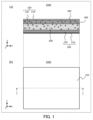
- FIG. 1 is a cross-sectional view and a plan view showing a schematic configuration of a battery 1000 according to a first embodiment.
- FIG. 2 is a cross-sectional view and a plan view showing a schematic configuration of a battery 1100 according to the second embodiment.
- FIG. 3 is a cross-sectional view and a plan view showing a schematic configuration of a battery 1200 according to the third embodiment.
- FIG. 4 is a cross-sectional view and a plan view showing a schematic configuration of a battery 1300 according to the fourth embodiment.
- FIG. 5 is a cross-sectional view and a plan view showing a schematic configuration of a battery 1400 according to the fifth embodiment.
- FIG. 6 is a cross-sectional view and a plan view showing a schematic configuration of a battery 1500 according to a sixth embodiment.
- the x-axis, y-axis, and z-axis represent the three axes of a three-dimensional Cartesian coordinate system.
- the z-axis direction is the thickness direction of the battery.
- the "thickness direction” refers to the direction perpendicular to the plane on which each layer of the battery is stacked.
- planar view refers to the battery viewed along the stacking direction of each layer in the battery.
- Thiickness in this specification refers to the length of the battery and each layer in the stacking direction.
- the “side surface” refers to the surface along the stacking direction of each layer in the battery, and the “main surface” refers to a surface other than the side surface.
- the terms “inside” and “outside” refer to the center side of the battery, as seen in the stacking direction of the layers in the battery, and the peripheral side of the battery, as seen in the stacking direction of the layers in the battery.
- the terms “above” and “below” in the battery configuration do not refer to the upward (vertically upward) and downward (vertically downward) directions in absolute spatial recognition, but are used as terms defined by the relative positional relationship based on the stacking order in the stacking configuration. Furthermore, the terms “above” and “below” are applied not only to cases where two components are arranged with a gap between them and another component exists between the two components, but also to cases where two components are arranged in close contact with each other and the two components are in contact.
- the battery according to the first embodiment includes a first electrode layer, a second electrode layer, and an electrolyte layer.
- the electrolyte layer is disposed between the first electrode layer and the second electrode layer.
- the battery according to the first embodiment satisfies at least one configuration selected from the group consisting of the following (I) and (II): (I) At least one selected from the group consisting of the first electrode layer, the second electrode layer, and the electrolyte layer contains an aluminum halide. (II) The battery according to the first embodiment further includes a side layer including an Al halide, the side layer being disposed on at least one side selected from the group consisting of the first electrode layer, the second electrode layer, and the electrolyte layer.
- the aluminum halide is represented by the following composition formula (1).
- X1 is at least one selected from the group consisting of F, Cl, Br, and I, and ⁇ satisfies 2.95 ⁇ 3.05.
- ⁇ may be 3. That is, the above Al halide may be represented by AlX13 .
- the aluminum halide has a relatively low melting point and is soft, so it can effectively act as a binder and stress absorber.
- X1 is F
- the aluminum halide has a relatively high melting point and is hard, so it can effectively act as a reinforcing material.
- the battery according to the first embodiment can effectively improve its strength against external impacts, thermal shocks, and stresses caused by the expansion and contraction of the battery due to charging and discharging or cooling and heating. Therefore, the battery according to the first embodiment can increase its mechanical strength and improve its reliability.
- the above effects can be achieved whether the battery according to the first embodiment satisfies the above configurations (I) and (II).
- the strength of the electrode layer and/or electrolyte layer, which are the power generating elements of the battery can be improved, thereby improving the reliability of the battery.
- structural defects i.e., cracks or peeling from the side
- structural defects i.e., cracks or peeling from the side
- the side layer containing aluminum halide thereby improving the reliability of the battery.
- the configuration example described below is an example in which the battery according to the first embodiment satisfies the above configuration (I) and the electrolyte layer is a solid electrolyte layer.
- the battery of the configuration example described below is, for example, an all-solid-state battery.
- FIG. 1 is a cross-sectional view and a plan view showing the general configuration of a battery 1000 according to a first embodiment.
- FIG. 1(a) shows a cross-sectional view of a battery 1000 according to the first embodiment.
- FIG. 1(b) shows a plan view of the battery 1000 according to the first embodiment as viewed from below in the z-axis direction.
- FIG. 1(a) shows a cross-section at the position indicated by line I-I in FIG. 1(b).
- the battery 1000 includes a first electrode layer 100, a second electrode layer 200 arranged parallel to and facing the first electrode layer 100, and a solid electrolyte layer 300 located between the first electrode layer 100 and the second electrode layer 200.
- the battery 1000 is a battery including the first electrode layer 100, the solid electrolyte layer 300, and the second electrode layer 200 in this order in the stacking direction.
- the first electrode layer 100 and the solid electrolyte layer 300 include an aluminum halide.
- the included aluminum halide may be particulate aluminum halide (hereinafter referred to as "an aluminum halide particle") 400.
- the battery 1000 is, for example, an all-solid-state battery.
- the first electrode layer 100 includes a first current collector 110 and a first active material layer 120.
- the first active material layer 120 includes halogenated Al particles 400.
- the second electrode layer 200 includes a second current collector 210 and a second active material layer 220.
- the solid electrolyte layer 300 includes halogenated Al particles 400, is located between the first active material layer 120 and the second active material layer 220, and is in contact with each of the first active material layer 120 and the second active material layer 220.
- the first electrode layer 100 and the solid electrolyte layer 300 include halogenated Al particles 400, but the second electrode layer 200 may also include halogenated Al particles 400.
- the first current collector 110, the first active material layer 120, the solid electrolyte layer 300, the second active material layer 220, and the second current collector 210 each have a schematic rectangular shape in a plan view.
- the shapes of these components are not limited to a rectangular shape.
- the current collector 110, the first active material layer 120, the solid electrolyte layer 300, the second active material layer 220, and the second current collector 210 are the same size and have the same outline in a plan view, but this is not limited to this.
- the first active material layer 120 may be smaller than the second active material layer 220.
- the first active material layer 120 and the second active material layer 220 may be smaller than the solid electrolyte layer 300.
- a portion of the solid electrolyte layer 300 may be in contact with at least one of the first current collector 110 and the second current collector 210.
- the first electrode layer 100 is a positive electrode layer
- the second electrode layer 200 is a negative electrode layer.
- the first current collector 110 is a positive electrode current collector
- the first active material layer 120 is a positive electrode active material layer
- the second current collector 210 is a negative electrode current collector
- the second active material layer 220 is a negative electrode active material layer.
- the first electrode layer 100 may be a negative electrode, and the second electrode layer 200 may be a positive electrode.
- the first current collector 110 may be a negative electrode current collector
- the first active material layer 120 may be a negative electrode active material layer.
- the second current collector 210 may be a positive electrode current collector
- the second active material layer 220 may be a positive electrode active material layer.
- the positive electrode active material layer and the negative electrode active material layer may be collectively referred to simply as “active material layer.”
- the positive electrode current collector and the negative electrode current collector may be collectively referred to simply as “current collector.”
- the current collector is formed of a material having electrical conductivity.
- Examples of the material of the current collector include stainless steel, nickel (Ni), aluminum (Al), iron (Fe), titanium (Ti), copper (Cu), palladium (Pd), gold (Au), platinum (Pt), or an alloy of two or more of these.
- a foil, plate, or mesh made of these materials can be used as the current collector.
- the material of the current collector may be selected taking into consideration the manufacturing process, the temperature of use, the pressure of use, the operating potential of the battery applied to the current collector, or electrical conductivity.
- the material of the current collector may also be selected according to the tensile strength or heat resistance required for the battery.
- the current collector may be a high-strength electrolytic copper foil or a clad material made by laminating foils of different metals.
- the thickness of the current collector is, for example, 10 ⁇ m or more and 100 ⁇ m or less.
- the surface of the current collector may be roughened to improve adhesion to the active material layer.
- the surface of the current collector may be coated with an adhesive component such as an organic binder.
- an adhesive component such as an organic binder.
- insulating particles, conductive particles, or semiconducting particles may be attached to the surface of the current collector. This strengthens the bonding at the interface between the current collector and other layers (e.g., active material layers), and can improve the mechanical and thermal reliability, as well as the cycle characteristics, of the battery 1000.
- the first active material layer 120 is, for example, a positive electrode active material layer.
- the first active material layer 120 is sandwiched between the first current collector 110 and the solid electrolyte layer 300.
- the first active material layer 120 may be in contact with a main surface of the first current collector 110.
- the first active material layer 120 may be in contact with a main surface of the solid electrolyte layer 300.
- the second active material layer 220 is, for example, a negative electrode active material layer.
- the second active material layer 220 is sandwiched between the second current collector 210 and the solid electrolyte layer 300.
- the second active material layer 220 may be in contact with the main surface of the second current collector 210.
- the second active material layer 220 may be in contact with the main surface of the solid electrolyte layer 300.
- the positive electrode active material layer contains a positive electrode active material.
- the positive electrode active material is a material in which metal ions such as lithium (Li) ions or magnesium (Mg) ions are inserted or removed from the crystal structure at a higher potential than the negative electrode, resulting in oxidation or reduction.
- the type of positive electrode active material can be appropriately selected depending on the type of battery, and known positive electrode active materials can be used.
- the positive electrode active material is, for example, a compound containing lithium and a transition metal element.
- the compound is, for example, an oxide containing lithium and a transition metal element, or a phosphate compound containing lithium and a transition metal element.
- oxides containing lithium and a transition metal element include lithium nickel composite oxides such as LiNi x M 1-x O 2 (wherein M is at least one selected from the group consisting of Co, Al, Mn, V, Cr, Mg, Ca, Ti, Zr, Nb, Mo, and W, and 0 ⁇ x ⁇ 1 is satisfied), layered oxides such as lithium cobalt oxide (LiCoO 2 ) and lithium nickel oxide (LiNiO 2 ), or lithium manganate having a spinel structure (e.g., LiMn 2 O 4 , Li 2 MnO 3 , or LiMnO 2 ).
- lithium nickel composite oxides such as LiNi x M 1-x O 2 (wherein M is at least one selected from the group consisting of Co, Al, Mn, V, Cr, Mg, Ca, Ti, Zr, Nb, Mo, and W, and 0 ⁇ x ⁇ 1 is satisfied
- layered oxides such as lithium cobalt oxide (LiCoO 2 ) and lithium nickel oxide (
- a phosphate compound containing lithium and a transition metal element is lithium iron phosphate (LiFePO 4 ) having an olivine structure.
- the positive electrode active material sulfur (S) and sulfides such as lithium sulfide (Li 2 S) may be used.
- the positive electrode active material particles may be coated with or may have lithium niobate (LiNbO 3 ) or the like added thereto.
- the positive electrode active material may be made of only one of these materials, or may be made of a combination of two or more of these materials.
- the positive electrode active material layer may contain an aluminum halide. This allows the aluminum halide to absorb external stress, expansion and contraction of the positive electrode active material due to charging and discharging, and stress due to expansion and contraction of the positive electrode active material due to thermal cycles, thereby improving the mechanical strength of the positive electrode active material layer and suppressing the occurrence of defects.
- the compatibility of the positive electrode active material layer with the solid electrolyte layer 300 e.g., expansion and contraction due to charging and discharging or expansion and contraction due to thermal cycles
- the aluminum halide may be aluminum halide particles 400.
- the positive electrode active material layer may contain, in addition to the positive electrode active material, a material other than the positive electrode active material and the aluminum halide. That is, the positive electrode active material layer may be a mixture layer. Examples of such materials are solid electrolytes such as inorganic solid electrolytes and sulfide solid electrolytes, conductive assistants such as acetylene black, or binding binders such as polyethylene oxide and polyvinylidene fluoride.
- the solid electrolyte may be, for example, a halide solid electrolyte. Examples of the halide solid electrolyte contained in the positive electrode active material layer are the same as the examples of the halide solid electrolyte contained in the solid electrolyte layer 300 described below.
- the positive electrode active material layer can improve the ionic conductivity within the positive electrode active material layer and can also improve the electronic conductivity.
- the positive electrode active material layer may have a thickness of, for example, 5 ⁇ m or more and 300 ⁇ m or less.
- the negative electrode active material layer contains a negative electrode active material.
- the negative electrode active material layer is a layer that is mainly composed of negative electrode materials such as negative electrode active materials.
- a negative electrode active material is a material in which metal ions such as lithium (Li) ions or magnesium (Mg) ions are inserted or removed from the crystal structure at a lower potential than the positive electrode, and oxidation or reduction occurs accordingly.
- the type of negative electrode active material can be appropriately selected depending on the type of battery, and known negative electrode active materials can be used.
- Examples of the negative electrode active material are carbon materials such as natural graphite, artificial graphite, graphite carbon fiber, and resin-sintered carbon, or alloy-based materials mixed with a solid electrolyte.
- Examples of the alloy-based materials are lithium alloys such as LiAl, LiZn, Li 3 Bi, Li 3 Cd, Li 3 Sb, Li 4 Si, Li 4.4 Pb, Li 4.4 Sn, Li 0.17 C, and LiC 6, oxides of lithium and transition metal elements such as lithium titanate (Li 4 Ti 5 O 12 ), zinc oxide (ZnO), or metal oxides such as silicon oxide (SiO x ).
- the negative electrode active material may be made of only one of these materials, or may be made of a combination of two or more of these materials.
- the negative electrode active material layer may contain, in addition to the negative electrode active material, a material other than the negative electrode active material.
- a material other than the negative electrode active material examples include solid electrolytes such as inorganic solid electrolytes and sulfide solid electrolytes, conductive assistants such as acetylene black, or binding binders such as polyethylene oxide and polyvinylidene fluoride.
- the solid electrolyte may be, for example, a halide solid electrolyte. Examples of halide solid electrolytes contained in the negative electrode active material layer are the same as the examples of halide solid electrolytes contained in the solid electrolyte layer 300 described below.
- the negative electrode active material layer may have a thickness of, for example, 5 ⁇ m or more and 300 ⁇ m or less.
- the negative electrode active material layer may contain aluminum halide, similar to the positive electrode active material layer described above.
- the solid electrolyte layer 300 includes a solid electrolyte.
- the solid electrolyte layer 300 contains, for example, a solid electrolyte as a main component.
- the main component refers to the component that is contained in the largest amount in terms of mass percentage in the solid electrolyte layer 300.
- the solid electrolyte layer 300 contains, for example, an aluminum halide.
- the aluminum halide is, for example, an aluminum halide particle 400.
- the solid electrolyte may be any known solid electrolyte for batteries that has ionic conductivity.
- the solid electrolyte contained in the solid electrolyte layer 300 may be, for example, a solid electrolyte that conducts metal ions such as lithium ions or magnesium ions.
- solid electrolyte a sulfide solid electrolyte, an oxide solid electrolyte, or a halide solid electrolyte can be used.
- Examples of sulfide-based solid electrolytes include Li2S - P2S5 - based, Li2S - SiS2- based, Li2S - B2S3 - based, Li2S - GeS2- based, Li2S -SiS2 - LiI-based, Li2S - SiS2 - Li3PO4 - based, Li2S - Ge2S2 -based, Li2S - GeS2 - P2S5 - based, and Li2S -GeS2 - ZnS -based.
- the oxide-based solid electrolyte is, for example, a lithium-containing metal oxide, a lithium-containing metal nitride, lithium phosphate (Li 3 PO 4 ), or a lithium-containing transition metal oxide.
- a lithium-containing metal oxide is Li 2 O—SiO 2 or Li 2 O—SiO 2 —P 2 O 5.
- An example of a lithium-containing metal nitride is Li x P y O 1-z N z (0 ⁇ z ⁇ 1).
- An example of a lithium-containing transition metal oxide is lithium titanium oxide.
- the halogenated solid electrolyte is, for example, a solid electrolyte that contains Li, at least one element selected from the group consisting of metal elements and metalloid elements other than Li, and a halogen element.
- Metalloid elements are B, Si, Ge, As, Sb, and Te.
- Metal elements are all elements in groups 1 to 12 of the periodic table (except hydrogen) and all elements in groups 13 to 16 of the periodic table (except B, Si, Ge, As, Sb, Te, C, N, P, O, S, and Se).
- the halide solid electrolyte is substantially free of sulfur.
- a halide solid electrolyte is substantially free of sulfur means that the halide solid electrolyte does not contain sulfur as a constituent element, except for sulfur that is inevitably mixed in as an impurity. In this case, the amount of sulfur mixed in as an impurity in the halide solid electrolyte is, for example, 1 mol % or less. It is more desirable that the halide solid electrolyte is free of sulfur.
- a solid electrolyte that does not contain sulfur is safe because it does not generate hydrogen sulfide even when exposed to the atmosphere.
- the solid electrolyte layer 300 includes, for example, a halide solid electrolyte.
- a halide solid electrolyte With this configuration, the thermal expansion characteristics of the halide solid electrolyte included in the solid electrolyte layer 300 and the Al halide particles 400 are easily matched because they are both halides. This strengthens the bonding interface between the Al halide particles 400 and the halide solid electrolyte. This suppresses the occurrence of structural defects caused by peeling at the bonding interface between the Al halide particles 400 and the halide solid electrolyte due to thermal shock or thermal cycling. In other words, with this configuration, the action and effect of the Al halide against thermal shock and thermal cycling is further improved. As a result, the reliability of the battery 1000 according to the first embodiment is further improved.
- the halide solid electrolyte may contain Al. According to this configuration, a solid electrolyte layer 300 containing a solid electrolyte having high ionic conductivity of, for example, 1 ⁇ S/cm or more can be obtained.
- the halide Al and the solid electrolyte are firmly bonded to each other, and it becomes easier to form an integrated bonded interface.
- the halide Al when the halide Al is contained in the solid electrolyte layer, the halide Al can coexist stably with the solid electrolyte in the solid electrolyte layer (for example, without forming fine defects around it).
- the halide solid electrolyte containing Al has excellent atmospheric stability and excellent heat resistance from about 700 ° C. to 800 ° C., so that even if AlF 3 having a high melting point is contained as the halide Al, the effect of containing AlF 3 can be obtained up to high temperatures.
- the halide solid electrolyte may include a first halide solid electrolyte including a crystal phase represented by the following composition formula (2).
- X2 is at least one selected from the group consisting of F, Cl, Br, and I.
- the first halide solid electrolyte has high ionic conductivity, atmospheric stability, and heat resistance, for example, 1 ⁇ S/cm or more. Therefore, the inclusion of the first halide solid electrolyte improves the ionic conductivity and reliability of the solid electrolyte layer 300.
- the crystal phase represented by Li 3 AlX2 6 can be confirmed by the diffraction pattern of the micro-area X-ray diffraction (XRD) described above, or by powder XRD using a powder sample obtained by cutting out the solid electrolyte.
- the composition of the solid electrolyte can also be evaluated by elemental analysis using, for example, an electron probe microanalyzer (EPMA) or energy dispersive X-ray spectroscopy (EDS).
- EPMA electron probe microanalyzer
- EDS energy dispersive X-ray spectroscopy
- the first halide solid electrolyte may include a crystal phase represented by the following composition formula (3). Li 3 AlF 6 ...Formula (3)
- the first halide solid electrolyte has improved atmospheric stability. This makes it possible to suppress fluctuations in the properties of the solid electrolyte caused by changes in the environment during the manufacturing process, and therefore makes it possible to reproducibly obtain a solid electrolyte layer 300 having the desired properties.
- strict dew point environment control, temperature control, and humidity control are no longer necessary, there are also manufacturing benefits, such as reduced manufacturing costs.
- the halide solid electrolyte may further include a second halide solid electrolyte having a different composition from the first halide solid electrolyte. This configuration further improves the adhesion of the solid electrolyte in the solid electrolyte layer 300, making the solid electrolyte layer 300 denser and improving the ionic conductivity.
- the second halide solid electrolyte may have a melting point lower than that of the first halide solid electrolyte. This makes it easier for the second halide solid electrolyte, which has a softer property due to its low melting point, to deform and fill the gaps between the first halide solid electrolytes when manufacturing the solid electrolyte layer 300 (e.g., when applying pressure for stacking). This makes it easier to densify the solid electrolyte layer 300.
- the second halide solid electrolyte which has a low melting point, is particularly prone to deformation.
- Densification improves the ionic conductivity of the solid electrolyte layer 300 and suppresses structural defects (e.g., voids and cracks). Fine voids and cracks, which are the starting point for the deterioration of characteristics due to external stress and thermal cycles, are reduced, resulting in a highly reliable solid electrolyte layer 300. This makes it possible to realize a battery 1000 with good performance and excellent reliability.
- the second halide solid electrolyte may be softer than the first halide solid electrolyte. This makes it easier for the second halide solid electrolyte, which has softer properties, to deform and fill the gaps between the first halide solid electrolytes when manufacturing the solid electrolyte layer (e.g., when applying pressure for stacking). This makes it easier to densify the solid electrolyte layer 300. Densification improves the ionic conductivity of the solid electrolyte layer 300 and suppresses structural defects (e.g., voids and cracks). Since fine voids and cracks, which are the starting points for the deterioration of characteristics due to external stress and thermal cycles, are reduced, a highly reliable solid electrolyte layer 300 can be obtained. Thus, a battery 1000 with good performance and excellent reliability can be realized.
- the softness of the second halide solid electrolyte and the first halide solid electrolyte can be compared by a method such as micro-Vickers.
- the second halide solid electrolyte may include a crystal phase represented by the following composition formula (4).
- M is at least one element selected from the group consisting of metal elements and metalloid elements having a valence of tetravalent.
- the second halide solid electrolyte containing the crystalline phase represented by composition formula (4) is softer than the first halide solid electrolyte. Therefore, the solid electrolyte layer 300 containing such a second halide solid electrolyte is easily densified. This improves the ionic conductivity in the solid electrolyte layer 300 and suppresses structural defects (e.g., voids and cracks). Since minute voids and cracks, which are the starting points for the deterioration of characteristics due to external stress and thermal cycles, are reduced, a highly reliable solid electrolyte layer 300 can be obtained. Therefore, a battery 1000 with good performance and excellent reliability can be realized.
- structural defects e.g., voids and cracks
- M may contain Ti, or M may be Ti. This increases the ionic conductivity of the second halide solid electrolyte to the same level as that of the first halide solid electrolyte (for example, 1 ⁇ S/cm or more). Thus, a solid electrolyte layer 300 having high ionic conductivity and high reliability can be obtained. Thus, a battery 1000 having excellent performance and reliability can be obtained.
- M is Ti
- the second halide solid electrolyte has a composition of Li 2 TiF 6
- it can have stable and soft properties up to a relatively high temperature, so that the solid electrolyte layer 300 can be densified and the ionic conductivity of the solid electrolyte layer 300 can be further improved (for example, to 3 ⁇ S/cm or more). Therefore, the effect of containing Al halide can be obtained up to a relatively high temperature.
- the solid electrolyte layer 300 may contain, in addition to the solid electrolyte, a bonding binder such as polyethylene oxide or polyvinylidene fluoride.
- the thickness of the solid electrolyte layer 300 may be 5 ⁇ m or more and 500 ⁇ m or less, 10 ⁇ m or more and 500 ⁇ m or less, or 5 ⁇ m or more and 150 ⁇ m or less.
- the solid electrolyte material may be composed of an agglomerate of particles.
- the solid electrolyte material may be composed of a sintered structure.
- the Al halide contained in the battery 1000 according to the first embodiment may be particulate, like the Al halide particles 400.
- the Al halide can be included in the coating layer of the solid electrolyte particles and the active material particles, or can be included inside the solid electrolyte particles. That is, when the Al halide is included in the electrode layer and the solid electrolyte layer, the options for the form of the Al halide are expanded.
- finely pulverized particles of the Al halide material for example, particles with a particle diameter of 1 ⁇ m or less
- the Al halide particles 400 are, for example, uniformly dispersed within the first electrode layer 100 and the solid electrolyte layer 300.
- the halogenated aluminum particles 400 may have an average particle size of, for example, 0.3 ⁇ m or more and 20 ⁇ m or less.
- the halogenated aluminum particles 400 are shown to have a spherical particle shape, but may have a particle shape other than spherical, such as a scale shape.
- the particle diameter of the Al halide particles 400 is preferably small. This allows the Al halide particles 400 to be uniformly dispersed throughout the first electrode layer 100 and the solid electrolyte layer 300, thereby increasing the surface area of the Al halide particles 400 and, as a result, increasing the bonding area between the Al halide particles 400 and the active material or solid electrolyte present therearound.
- the mechanical reliability (flexural strength) of the first electrode layer 100 and the solid electrolyte layer 300 is further improved by miniaturizing the Al halide particles 400 (for example, miniaturizing the particle diameter to 1 ⁇ m or less).
- the Al halide includes, for example, AlF 3.
- the Al halide may be AlF 3.
- the mechanical bonding between the solid electrolyte particles and between the active material particles i.e., the anchor effect
- the solid electrolyte particle can be made harder.
- AlF 3 also serves as an anchor that strengthens the bonding between the particles. Therefore, a battery with excellent bending resistance and impact resistance is obtained.
- AlF 3 has excellent heat resistance (for example, about 1000 ° C.). Therefore, when AlF 3 is included, the battery 1000 can obtain excellent reliability even at high temperatures.
- AlF3 may have an orthorhombic and/or trigonal crystal structure.
- the desired crystal structure can be obtained by heat treatment conditions.
- AlF 3 having an orthorhombic crystal structure has excellent heat resistance, for example, stable even at high temperatures of about 400 ° C.
- AlF 3 having an orthorhombic crystal structure can have heat resistance, for example, in a temperature range of 400 ° C. or more and 1000 ° C. or less.
- AlF 3 having an orthorhombic crystal structure is hard, it also contributes to improving the mechanical strength of the battery 1000. Therefore, by including AlF 3 having an orthorhombic crystal structure in the electrode layer and/or solid electrolyte layer 300, both the heat resistance and mechanical strength of the battery 1000 can be improved.
- the organic binder included in the all-solid-state battery softens rapidly at or above the glass transition point, for example, 100 ° C. or more and 250 ° C. or less. Therefore, by including AlF 3 having an orthorhombic crystal structure in the electrode layer and/or solid electrolyte layer 300, the decrease in the mechanical strength of the battery 1000 at high temperatures, for example, exceeding 100 ° C., can be suppressed
- the surface of the AlF3 particle may be coated with a coating layer containing a solid electrolyte.
- the solid electrolyte coating the AlF3 particle acts as a binder. Therefore, the bonding between the AlF3 particles or between the AlF3 particle and other particles (e.g., solid electrolyte particles and active material particles) is improved, and the reliability of the battery is further improved.
- the ionic conductivity of the solid electrolyte layer is improved by including the AlF3 particles having such a configuration in the solid electrolyte layer.
- AlF3 having a trigonal crystal structure is softer than AlF3 having an orthorhombic crystal structure, for example, softer than a solid electrolyte. Therefore, by including AlF3 having a trigonal crystal structure in the electrode layer and/or solid electrolyte layer 300, the binding strength of the solid electrolyte particles and the active material particles at high temperatures can be improved.
- AlF3 having a combination of an orthorhombic crystal structure and a trigonal crystal structure may be included in the electrode layer and/or the solid electrolyte layer 300. This allows the mechanical strength, heat resistance, and binding property to be adjusted by controlling the ratio of the crystal systems.
- the AlF 3 contained in the electrode layer and/or the solid electrolyte layer 300 may contain a first crystal phase having an orthorhombic crystal structure and a second crystal phase having a trigonal crystal structure.
- a first crystal phase having an orthorhombic crystal structure and a second crystal phase having a trigonal crystal structure.
- the expansion and contraction of the active material and heat generation due to the cooling and heating cycles and the charge and discharge cycles can be absorbed by AlF 3 .
- the crystal system of AlF3 can be identified, for example, by a diffraction pattern obtained by micro X-ray diffraction (micro XRD) of the side surface of the electrode layer and the solid electrolyte layer 300 exposed on the side surface of the battery 1000. Alternatively, it can be confirmed by a lattice image of a high-resolution transmission electron microscope (TEM).
- micro XRD micro X-ray diffraction
- the AlF3 may be particulate, and in the surface region of the AlF3 particle, the content of the first crystal phase may be greater than the content of the second crystal phase, and in the internal region of the AlF3 particle, the content of the second crystal phase may be greater than the content of the first crystal phase.
- a composite particle containing an orthorhombic crystal structure and a trigonal crystal structure in one particle may be used.
- the AlF3 particle can obtain an anchor effect obtained by the hard surface layer even at high temperatures, and can also be provided with deformability due to the particle interior that is softer than the surface layer. Therefore, the solid electrolyte layer and/or electrode layer containing the AlF3 particles can be easily densified, and the bonding between the solid electrolyte particles and the active material particles is also improved. Therefore, a battery with improved reliability can be obtained.
- the morphology of the composite particles described above can be evaluated, for example, by SEM observation of the cross section of an ion-polished battery.
- AlF3 is a composite particle as described above, that is, when AlF3 containing an orthorhombic crystal structure and a trigonal crystal structure is particulate, at least a part of the surface of the AlF3 particle may be covered with a coating layer containing a solid electrolyte. This improves the bonding between AlF3 and the solid electrolyte contained in the electrolyte layer or electrode layer. Therefore, the reliability of the solid electrolyte layer or electrode layer against thermal shock and external stress is improved.
- the AlF 3 particles may contain first particles composed of AlF 3 having an orthorhombic crystal structure, and second particles containing a first crystal phase having an orthorhombic crystal structure and a second crystal phase having a trigonal crystal structure. This allows the heat resistance, mechanical strength, deformability, and compactness of AlF 3 to be adjusted according to the application by controlling the mixing ratio of the first particles and the second particles.
- the average particle size of the second particles may be larger than the average particle size of the first particles. This allows the highly deformable second crystal phase to reduce voids that tend to form around the larger second particles, making it possible to densify the electrolyte layer and electrode layer. This improves the electrical characteristics and reliability of the battery 1000.
- the content of aluminum halide may be, for example, 0.01 volume % or more and 5 volume % or less in the solid electrolyte layer 300, and may be, for example, 0.01 volume % or more and 3 volume % or less in the first electrode layer 100.
- Such aluminum halide content can be confirmed by elemental analysis using a high-resolution composition map such as EPMA of a cross section processed by ion polishing or the like.
- the aluminum halide may be dispersed in the solid electrolyte layer 300 and/or the electrode layer and be present between or in voids between the solid electrolyte particles and/or the active material particles, or may be contained in the solid electrolyte layer 300 and/or the electrode layer in another form.
- an aluminum halide may be included in the coating layer that covers at least a portion of the surface of the solid electrolyte material particles and/or the active material particles. This enhances the mechanical bonding (i.e., anchor effect) between the solid electrolyte particles and/or between the active material particles, improving the reliability of the battery 1000 against external stresses and thermal cycles of the solid electrolyte layer 300 and/or the electrode layer.
- the coating layer may include an aluminum halide.
- This configuration can enhance the adhesion and mechanical bonding between the active material particles (i.e., the anchor effect). This improves the strength of the electrode layer against external stress and thermal cycles, and can suppress the occurrence of structural defects such as cracks in the electrode layer. This can further improve the reliability of the battery 1000.
- the coating layer may include an aluminum halide.
- This configuration can enhance the adhesion and mechanical bonding (i.e., anchor effect) between the solid electrolyte particles included in the electrode layer and/or the solid electrolyte layer 300, which are the power generating elements of the battery 1000. This improves the strength of the power generating elements against external stress and thermal cycles, and can further improve the reliability of the battery 1000.
- At least one selected from the group consisting of the first electrode layer 100, the second electrode layer 200, and the solid electrolyte layer 300 may contain solid electrolyte particles, and the solid electrolyte particles may contain an aluminum halide.
- the aluminum halide may be contained inside the solid electrolyte particles.
- at least a part of the surface of the aluminum halide particles may be covered with a coating layer containing a solid electrolyte.
- the hardness of the solid electrolyte particles can be adjusted by selecting a halogen element in the aluminum halide material, or by including a combination of multiple halogen elements.
- the aluminum halide material is contained inside the solid electrolyte particles, the decrease in ionic conductivity between the solid electrolyte particles caused by the aluminum halide material is reduced.
- the solid electrolyte particles containing Al halide can be produced by, for example, using a raw material containing Al halide or a substance that produces Al halide as an intermediate product as a starting raw material for synthesizing the solid electrolyte particles, and controlling the synthesis conditions of the solid electrolyte (for example, heat treatment conditions or conditions of mechanical energy applied during mechanochemical treatment, etc.). That is, by using synthesis conditions in which Al halide exists inside the particles and the synthesized solid electrolyte exists on the particle surface, the solid electrolyte particles containing Al halide can be produced.
- synthesis conditions in which Al halide exists inside the particles and the synthesized solid electrolyte exists on the particle surface the solid electrolyte particles containing Al halide can be produced.
- the solid electrolyte particles containing Al halide can be produced more easily.
- the solid electrolyte particles containing Al halide can also be produced more easily.
- it is also possible to produce solid electrolyte particles that contain aluminum halide by coating the surface of the aluminum halide particles with a solid electrolyte film.
- Al halide may be included at the bonding interface between the solid electrolyte layer 300 and the electrode layer. This configuration improves the bonding between the solid electrolyte layer 300 and the electrode layer, suppressing delamination that is likely to occur due to external impacts and thermal cycles.
- the presence of aluminum halide in the battery 1000 can be determined by EPMA, EDS, and X-ray fluorescence spectrometry (XRF).
- the form and composition can be analyzed by composition analysis (point analysis or area analysis) using EPMA and EDS, etc., of a polished cross section processed with an ion polisher, etc.
- the solid electrolyte layer 300 and/or the electrode layer can be made dense, and resistance loss can be realized by reducing the resistance.
- the softness of the aluminum halide may be adjusted depending on the purpose. For example, multiple types of aluminum halide may be used in combination. This improves the mechanical strength of the battery 1000 and suppresses the occurrence of structural defects due to external impacts, charge/discharge cycles, and thermal cycles.
- FIG. 2 is a cross-sectional view and a plan view showing the general configuration of the battery 1100 of the second embodiment.
- FIG. 2(a) is a cross-sectional view of the battery 1100 of the second embodiment.
- FIG. 2(b) is a plan view of the battery 1100 of the second embodiment as viewed from below in the z-axis direction.
- FIG. 2(a) shows a cross-sectional view taken along dotted line II-II in FIG. 2(b).
- the battery 1100 according to the second embodiment has a different solid electrolyte layer configuration from the battery 1000 according to the first embodiment.
- the solid electrolyte layer 301 in the battery 1100 according to the second embodiment differs in that the Al halide particles 400 contained as Al halide are unevenly distributed in the region of the solid electrolyte layer 301 that contacts the first active material layer 120, and are not contained in the region that contacts the second active material layer 220.
- This configuration makes it possible to selectively contain Al halide in the electrode layer where structural defects are likely to occur, for example, in the region on the electrode layer side that contains an active material that expands and contracts greatly during charging and discharging, or has a large thermal expansion coefficient. This makes it possible to efficiently improve the reliability of the battery 1100.
- the concentration of the Al halide particles 400 in the region of the solid electrolyte layer 301 that contacts the first active material layer 120 is higher than the concentration of the Al halide particles 400 in the region of the solid electrolyte layer 301 that contacts the second active material layer 220.
- This configuration can also efficiently improve the reliability of the battery 1100.
- FIG. 3 is a cross-sectional view and a plan view showing the general configuration of a battery 1200 according to a third embodiment.
- FIG. 3(a) is a cross-sectional view of the battery 1200 of the third embodiment.
- FIG. 3(b) is a plan view of the battery 1200 of the third embodiment as viewed from below in the z-axis direction.
- FIG. 3(a) shows a cross section taken along the line III-III in FIG. 3(b).
- the battery 1200 according to the third embodiment has a different solid electrolyte layer configuration from the battery 1000 according to the first embodiment.
- the solid electrolyte layer 302 in the battery 1100 according to the second embodiment includes a first layer 302a in contact with the first electrode layer 100 and a second layer 302b in contact with the second electrode layer 200.
- the first layer 302a and the second layer 302b include solid electrolytes having different compositions.
- the first layer 302a includes Al halide particles 400 as Al halide.
- the second layer 302b does not include Al halide.
- the solid electrolyte material in contact with the first electrode layer 100 and the solid electrolyte material in contact with the second electrode layer 200 may be made of different materials.
- a configuration may be used in which a halide solid electrolyte is used as the solid electrolyte material on the positive electrode layer side and a sulfide solid electrolyte is used as the solid electrolyte material on the negative electrode layer side.
- the solid electrolyte layer is formed of two or more layers made of different materials, selectively including an aluminum halide in the layer using a material that is prone to structural defects can selectively suppress defects. Therefore, the reliability of the battery 1200 can be efficiently improved.
- both the first layer 302a and the second layer 302b contain halogenated Al particles 400, and the concentration of the halogenated Al particles 400 in the first layer 302a is higher than the concentration of the halogenated Al particles 400 in the second layer 302b.
- This configuration can also efficiently improve the reliability of the battery 1200.
- FIG. 4 is a cross-sectional view and a plan view showing the general configuration of a battery 1300 according to a fourth embodiment.
- FIG. 4(a) is a cross-sectional view of the battery 1300 of the fourth embodiment.
- FIG. 4(b) is a plan view of the battery 1300 of the fourth embodiment as viewed from below in the z-axis direction.
- FIG. 4(a) shows a cross section taken along the line IV-IV in FIG. 4(b).
- the battery 1300 according to the fourth embodiment differs from the battery 1000 according to the first embodiment in that it further includes a side layer 500 containing an aluminum halide, which is disposed on at least one side surface selected from the group consisting of the first electrode layer 100, the second electrode layer 200, and the electrolyte layer 300.
- the battery 1300 according to the fourth embodiment satisfies the above configuration (II).
- the battery 1300 according to the fourth embodiment can suppress external stress from the side and suppress the occurrence of structural defects in the side portion. As a result, the reliability of the battery 1200 is further improved.
- the side layer 500 contains an aluminum halide.
- the description of the aluminum halide contained in the side layer 500 is the same as that of the aluminum halide described in the first embodiment, and therefore a detailed description is omitted here.
- the side layer 500 may contain, for example, halogenated Al particles and an organic binder for bonding.
- the side layer 500 can be formed, for example, by applying a paste containing halogenated Al particles and an organic binder onto at least one side surface selected from the group consisting of the first electrode layer 100, the second electrode layer 200, and the electrolyte layer 300, and drying the coating.
- the thickness of the side layer 500 may be, for example, 1 ⁇ m or more and 30 ⁇ m or less.
- the battery 1300 according to the fourth embodiment has a configuration in which an aluminum halide is also contained in the power generating element, i.e., it also satisfies the above-mentioned configuration (I), but it does not have to satisfy the above-mentioned configuration (I). In other words, the aluminum halide does not have to be contained in the power generating element.
- FIG. 5 is a cross-sectional view and a plan view showing the general configuration of a battery 1400 according to a fifth embodiment.
- FIG. 5(a) is a cross-sectional view of the battery 1400 of the fifth embodiment.
- FIG. 5(b) is a plan view of the battery 1400 of the fifth embodiment as viewed from below in the z-axis direction.
- FIG. 5(a) shows a cross section taken at the position indicated by the line V-V in FIG. 5(b).
- the battery 1400 according to the fifth embodiment differs from the battery 1000 according to the first embodiment in that only the first electrode layer 100 contains Al halide particles 400 as Al halide.
- This configuration can suppress the problem of structural defects occurring easily in layers (e.g., electrode layers) that expand and contract significantly during charge/discharge cycles and thermal cycles. As a result, the reliability of the battery 1400 is improved.
- FIG. 6 is a cross-sectional view and a plan view showing the general configuration of a battery 1500 according to a sixth embodiment.
- FIG. 6(a) is a cross-sectional view of a battery 1500 according to a sixth embodiment.
- FIG. 6(b) is a plan view of the battery 1500 according to the sixth embodiment as viewed from below in the z-axis direction.
- FIG. 6(a) shows a cross section taken along the line VI-VI in FIG. 6(b).
- the battery 1500 according to the sixth embodiment differs from the battery 1000 according to the first embodiment in that the concentrations of the aluminum halide contained in the first electrode layer and the solid electrolyte layer are different in each layer.
- the concentration of the halogenated Al particles 400 is higher on the outer periphery (side surface).
- the concentration of the halogenated Al particles 400 changes gradually and continuously as it approaches the outer periphery, but it may also change in a stepwise manner.
- the outer periphery of the first electrode layer 101 e.g., the first active material layer 121 and the solid electrolyte layer 303, which are easily damaged by external impact (or easily peeled off (interlayer, intralayer) during charge/discharge or thermal cycles), can be surrounded by a high concentration of Al halide particles 400.
- the area with high concentration of Al halide particles 400 may be, for example, rectangular, circular, polygonal, or other shapes in plan view, and high reliability can be achieved by surrounding the outer periphery and making it a shape that can protect the inside of the battery.
- an all-solid-state battery has been described as an example, but the battery of the present disclosure is not limited to an all-solid-state battery and may be a liquid battery. That is, in the battery of the present disclosure, the electrolyte layer may be composed of, for example, an electrolyte solution and a separator impregnated with the electrolyte solution. Even in the case of a liquid battery, a highly reliable battery can be realized by including an aluminum halide, as in the all-solid-state batteries described in the first to sixth embodiments.
- At least one selected from the group consisting of the first electrolyte layer and the second electrode layer contains an aluminum halide.
- the aluminum halide is contained, for example, in a coating layer that covers at least a portion of the surface of the active material particles contained in the electrolyte layer.
- This coating layer may contain, for example, a solid electrolyte and an aluminum halide.
- the first electrode layer 100 is a positive electrode layer and the second electrode layer 200 is a negative electrode layer. That is, in the following description, the first active material layer 120 is a positive electrode active material layer, the first current collector 110 is a positive electrode current collector, the second active material layer 220 is a negative electrode active material layer, and the second current collector 210 is a negative electrode current collector.
- pastes for printing the positive and negative active material layers are prepared.
- the solid electrolyte for the positive and negative active material layers for example, a powder of a solid electrolyte (Li 3 AlF 6 -Li 2 TiF 6 ) having an average particle size of about 3 ⁇ m and containing a halide as a main component is prepared.
- this powder for example, one having high ionic conductivity (for example, 1 ⁇ 10 -3 S/cm to 3 ⁇ 10 -3 S/cm) is used.
- the positive electrode active material for example, a powder of LiNiCoAl composite oxide ( LiNi0.8Co0.15Al0.05O2 ) having a layered structure and an average particle size of about 5 ⁇ m is used. Furthermore, as the Al halide material, an Al fluoride powder having an average particle size of about 1 ⁇ m is prepared.
- a paste for a positive electrode active material layer is prepared by dispersing a mixture containing the above-mentioned positive electrode active material, the above-mentioned solid electrolyte powder, and Al fluoride (AlF 3 ) powder in an organic solvent or the like using a triple roll roller.
- the negative electrode active material for example, a powder of natural graphite with an average particle size of about 10 ⁇ m is used.
- a paste for the negative electrode active material layer is prepared in the same manner as the paste for the positive electrode active material layer, by dispersing a mixture containing the above-mentioned negative electrode active material and the above-mentioned powder of the solid electrolyte in an organic solvent or the like.
- copper foil having a thickness of about 30 ⁇ m is prepared as a material used as a positive electrode collector and a negative electrode collector.
- the paste for the positive electrode active material layer and the paste for the negative electrode active material layer are printed on one surface of each copper foil by a screen printing method in a predetermined shape and with a thickness of about 50 ⁇ m to 100 ⁇ m.
- the paste for the positive electrode active material layer and the paste for the negative electrode active material layer are dried at 80 ° C. to 130 ° C. to a thickness of 30 ⁇ m to 60 ⁇ m.
- the paste for the positive electrode active material layer contains AlF 3 powder. This results in a collector (copper foil) on which the positive electrode active material layer and the negative electrode active material layer are formed, respectively.
- a paste for a solid electrolyte layer dispersed in an organic solvent or the like is prepared by including Al fluoride (AlF 3 ) powder.
- AlF 3 Al fluoride
- the above-mentioned paste for a solid electrolyte layer containing AlF 3 powder is printed, for example, to a thickness of about 100 ⁇ m, on the main surface of the positive electrode active material layer formed on the positive electrode current collector using a metal mask.
- the above-mentioned paste for a solid electrolyte layer containing AlF 3 powder is printed, for example, to a thickness of about 100 ⁇ m, on the main surface of the negative electrode active material layer formed on the negative electrode current collector using a metal mask.
- the positive electrode active material layer and the negative electrode active material layer on whose main surfaces the paste for a solid electrolyte layer is printed are dried at 80° C. to 130° C.
- the solid electrolyte printed on the positive electrode active material layer formed on the positive electrode current collector and the solid electrolyte printed on the negative electrode active material layer formed on the negative electrode current collector are laminated so that they are in contact with each other and face each other, and the resulting laminate is placed in a die mold with a rectangular outer shape.
- an elastic sheet having a thickness of, for example, about 50 ⁇ m to 100 ⁇ m and an elastic modulus of about 5 ⁇ 10 6 Pa is inserted between the pressing die and the laminate.
- pressure is applied to the laminate via the elastic sheet.
- the pressing die is pressed for, for example, about 90 seconds while being heated to 50° C. to 80° C. at a pressure of 300 MPa to 350 MPa.
- a battery including a positive electrode layer, a negative electrode layer, and an electrolyte layer disposed between the positive electrode layer and the negative electrode layer.
- the battery manufacturing method is not limited to the above example.
- Printing methods that may be used include, for example, a doctor blade method, a calendar method, a spin coating method, a dip coating method, an inkjet method, an offset method, a die coating method, and a spray method.
- a battery comprising: The battery satisfies at least one configuration selected from the group consisting of (I) and (II) below: (I) At least one selected from the group consisting of the first electrode layer, the second electrode layer, and the electrolyte layer contains an aluminum halide. (II) The battery further includes a side layer including an aluminum halide, the side layer being disposed on at least one side selected from the group consisting of the first electrode layer, the second electrode layer, and the electrolyte layer.
- the Al halide is represented by the following composition formula (1): AlX1 ⁇ ...Formula (1)
- X1 is at least one selected from the group consisting of F, Cl, Br, and I, and ⁇ satisfies 2.95 ⁇ 3.05. battery.
- the aluminum halide has a relatively low melting point and is soft, so it can effectively act as a binder and stress absorber.
- X1 is F
- the aluminum halide has a relatively high melting point and is hard, so it can effectively act as a reinforcing material.
- the battery of technology 1 can effectively improve its strength against external impacts, thermal shocks, and stresses caused by the expansion and contraction of the battery due to charging and discharging or cooling and heating. Therefore, the battery of technology 1 can increase its mechanical strength and improve its reliability.
- the above effects can be achieved with either the configuration (I) or (II) above.
- the configuration (I) above when the configuration (I) above is satisfied, the strength of the electrode layer and/or electrolyte layer, which are the power generating elements of the battery, can be improved, improving the reliability of the battery.
- structural defects i.e., cracks or peeling from the side
- structural defects i.e., cracks or peeling from the side
- the side layer containing aluminum halide improving the reliability of the battery.
- the electrolyte layer is a solid electrolyte layer.
- This configuration makes it possible to provide an all-solid-state battery with improved reliability.
- the solid electrolyte layer includes a halide solid electrolyte.
- the thermal expansion characteristics of the halide solid electrolyte contained in the solid electrolyte layer and the aluminum halide are easily matched because they are both halides.
- the action and effect of the aluminum halide against thermal shock and thermal cycles is further improved. Therefore, a more reliable battery is obtained.
- the electrolyte layer is composed of an electrolytic solution and a separator impregnated with the electrolytic solution.
- This configuration makes it possible to provide a liquid battery with improved reliability.
- the battery satisfies (I), at least one selected from the group consisting of the first electrode layer, the second electrode layer, and the electrolyte layer includes solid electrolyte particles and a coating layer that coats at least a portion of a surface of the solid electrolyte particles;
- the coating layer contains the Al halide.
- This configuration can improve the adhesion and mechanical bonding (i.e., anchor effect) between the solid electrolyte particles contained in the electrode layer and/or electrolyte layer, which are the power generation elements of the battery. This improves the strength of the power generation elements against external stress and thermal cycles, thereby further improving the reliability of the battery.
- the battery satisfies (I), at least one selected from the group consisting of the first electrode layer, the second electrode layer, and the electrolyte layer contains solid electrolyte particles;
- the Al halide is contained inside the solid electrolyte particles.
- the hardness of the solid electrolyte particles contained in the electrode layer and/or electrolyte layer, which are the power generating elements of the battery can be adjusted according to the purpose, such as making them softer to improve deformability or harder to improve strength. This improves the reliability of the power generating element against external stress and thermal cycles, thereby further improving the reliability of the battery.
- the hardness of the solid electrolyte particles can be adjusted by selecting a halogen element in the halogenated aluminum material, or by including a combination of multiple halogen elements.
- the halogenated aluminum material is contained inside the solid electrolyte particles, the decrease in ionic conductivity between the solid electrolyte particles caused by the halogenated aluminum material is reduced.
- the battery satisfies (I), At least one selected from the group consisting of the first electrode layer and the second electrode layer includes active material particles and a coating layer that coats at least a portion of a surface of the active material particles, The coating layer contains the Al halide.
- the battery according to any one of claims 1 to 6.
- This configuration can improve the adhesion and mechanical bonding between the active material particles (i.e., the anchor effect). This improves the strength of the electrode layer against external stress and thermal cycles, and can suppress the occurrence of structural defects such as cracks in the electrode layer. This can further improve the reliability of the battery.
- This configuration makes it easier to incorporate the aluminum halide into the coating layers of the solid electrolyte particles and active material particles, or into the interior of the solid electrolyte particles.
- finely pulverized aluminum halide particles e.g., particles with a particle diameter of 1 ⁇ m or less
- the Al halide includes AlF3 ;
- the mechanical bonding between solid electrolyte particles and between active material particles is improved by the presence of hard AlF3 particles.
- the solid electrolyte particles can be made harder.
- AlF3 when AlF3 is contained in the coating layer of the solid electrolyte particles and/or the active material particles, AlF3 also serves as an anchor that strengthens the bonding between the particles. Therefore, a battery with excellent flexural strength and impact resistance is obtained.
- AlF3 has excellent heat resistance (for example, about 1000°C). Therefore, excellent reliability can be obtained even at high temperatures.
- AlF3 that is stable even at high temperatures, for example, around 400°C. Therefore, AlF3 with excellent mechanical strength and heat resistance can be contained in the battery, resulting in a more reliable battery.
- the crystal system of AlF3 can be identified, for example, by the diffraction pattern obtained by micro-XRD of the surface exposed on the side surface of the battery. Alternatively, it can be confirmed by a lattice image of a high-resolution TEM.
- the AlF3 is in particulate form, At least a portion of the surface of the AlF3 particles is coated with a coating layer containing a solid electrolyte.
- the solid electrolyte covering the AlF3 particles acts as a binder. Therefore, the bonding between the AlF3 particles or between the AlF3 particles and other particles (e.g., solid electrolyte particles and active material particles) is improved, and the reliability of the battery is further improved. For example, by including the AlF3 particles having such a configuration in the solid electrolyte layer, the ionic conductivity of the solid electrolyte layer is also improved.
- the AlF3 includes a first crystal phase having an orthorhombic crystal structure and a second crystal phase having a trigonal crystal structure;
- This provides AlF3 that is softer than single crystal AlF3 having an orthorhombic crystal structure while having heat resistance at relatively high temperatures, for example, about 200°C to 400°C. Therefore, by including such AlF3 in a battery, it is possible to improve the binding of the solid electrolyte particles and the active material particles at high temperatures. This allows AlF3 to absorb the expansion and contraction of the active material and heat generation due to cooling and heating cycles and charge and discharge cycles.
- the AlF3 is in particulate form, In the surface region of the AlF3 particle, the content of the first crystal phase is greater than the content of the second crystal phase; In the inner region of the AlF3 particle, the content of the second crystal phase is greater than the content of the first crystal phase; 13.
- the AlF3 particles can obtain an anchor effect even at high temperatures due to the hard surface layer, and can also provide deformability due to the inside of the particles which is softer than the surface layer. Therefore, the solid electrolyte layer and/or electrode layer containing the AlF3 particles can be easily densified, and the bonding between the solid electrolyte particles and the active material particles is also improved. Therefore, a battery with improved reliability can be obtained.
- the AlF3 is in particulate form, At least a portion of the surface of the AlF3 particles is coated with a coating layer containing a solid electrolyte. 14. The battery according to claim 12 or 13.
- the Al halide comprises particulate AlF3 ,
- the AlF3 particles are A first particle composed of AlF3 having a cubic crystal structure; second particles including a first crystal phase having an orthorhombic crystal structure and a second crystal phase having a trigonal crystal structure; Including, The battery according to claim 9.
- the average particle size of the second particles is larger than the average particle size of the first particles. 16. The battery according to claim 15.
- the highly deformable second crystal phase can reduce voids that tend to form around the larger second particles, making it possible to densify the electrolyte layer and electrode layer. This improves the electrical characteristics and reliability of the battery.
- the halide solid electrolyte includes a first halide solid electrolyte including a crystal phase represented by the following composition formula (2): Li3AlX26 ... Formula (2)
- X2 is at least one selected from the group consisting of F, Cl, Br, and I. 18.
- the solid electrolyte layer contains a solid electrolyte having high ionic conductivity, for example, 1 ⁇ S/cm or more, atmospheric stability, and heat resistance, so that the ionic conductivity and reliability of the solid electrolyte layer are improved.
- the crystal phase represented by Li 3 AlX2 6 can be confirmed by the diffraction pattern of the micro-part XRD described above, or by powder XRD using a powder sample obtained by cutting out the solid electrolyte.
- the composition of the solid electrolyte can also be evaluated by elemental analysis, for example, by EPMA or EDS.
- the first halide solid electrolyte includes a crystalline phase represented by the following composition formula (3): Li 3 AlF 6 ...Formula (3) 19.
- the first halide solid electrolyte has improved atmospheric stability. This makes it possible to suppress fluctuations in the properties of the solid electrolyte caused by changes in the environment during the manufacturing process, and therefore makes it possible to reproducibly obtain a solid electrolyte layer with the desired properties.
- manufacturing benefits such as reduced manufacturing costs, because strict dew point environment control, temperature control, and humidity control are no longer necessary.
- the halide solid electrolyte further includes a second halide solid electrolyte having a composition different from that of the first halide solid electrolyte.
- This configuration further improves the adhesion of the solid electrolyte in the solid electrolyte layer, making the solid electrolyte layer more dense and improving the ionic conductivity.
- the second halide solid electrolyte has a lower melting point than the first halide solid electrolyte. 21.
- the second halide solid electrolyte which has a softer property due to its low melting point, is more likely to deform and fill the gaps between the first halide solid electrolyte. This makes it easier to densify the solid electrolyte layer.
- the second halide solid electrolyte which has a low melting point, is particularly prone to deformation. Densification improves the ionic conductivity in the solid electrolyte layer and suppresses structural defects (e.g., voids and cracks). Fine voids and cracks, which are the starting point for the deterioration of characteristics due to external stress and thermal cycles, are reduced, resulting in a highly reliable solid electrolyte layer. This makes it possible to realize a battery with good performance and excellent reliability.
- the second halide solid electrolyte is softer than the first halide solid electrolyte. 22.
- the second halide solid electrolyte which has softer properties, is more likely to deform and fill the gaps between the first halide solid electrolytes.
- Densification improves the ionic conductivity in the solid electrolyte layer and suppresses structural defects (e.g., voids and cracks). Fine voids and cracks, which are the starting points for the deterioration of characteristics due to external stress and thermal cycles, are reduced, resulting in a highly reliable solid electrolyte layer. This makes it possible to realize a battery with good performance and excellent reliability.
- the softness of the second halide solid electrolyte and the first halide solid electrolyte can be compared using methods such as micro-Vickers.
- the second halide solid electrolyte includes a crystalline phase represented by the following composition formula (4): Li 2 MF 6 ...(4)
- the M is at least one element selected from the group consisting of metal elements and semi-metal elements having a valence of tetravalent. 23.
- the M includes Ti. 24. The battery according to claim 23.
- the ionic conductivity of the second halide solid electrolyte is increased to the same level as that of the first halide solid electrolyte (e.g., 1 ⁇ S/cm or more). This makes it possible to obtain a solid electrolyte layer with high ionic conductivity and high reliability. This makes it possible to obtain a battery with excellent performance and reliability.
- the battery disclosed herein can be used, for example, as a secondary battery such as an all-solid-state battery or liquid battery for use in various electronic devices or automobiles.
Landscapes
- Chemical & Material Sciences (AREA)
- Chemical Kinetics & Catalysis (AREA)
- Electrochemistry (AREA)
- General Chemical & Material Sciences (AREA)
- Engineering & Computer Science (AREA)
- Manufacturing & Machinery (AREA)
- Physics & Mathematics (AREA)
- Condensed Matter Physics & Semiconductors (AREA)
- General Physics & Mathematics (AREA)
- Inorganic Chemistry (AREA)
- Secondary Cells (AREA)
- Battery Electrode And Active Subsutance (AREA)
Priority Applications (2)
| Application Number | Priority Date | Filing Date | Title |
|---|---|---|---|
| JP2025535634A JPWO2025022869A1 (https=) | 2023-07-21 | 2024-06-17 | |
| CN202480044382.XA CN121444239A (zh) | 2023-07-21 | 2024-06-17 | 电池 |
Applications Claiming Priority (2)
| Application Number | Priority Date | Filing Date | Title |
|---|---|---|---|
| JP2023-119501 | 2023-07-21 | ||
| JP2023119501 | 2023-07-21 |
Publications (1)
| Publication Number | Publication Date |
|---|---|
| WO2025022869A1 true WO2025022869A1 (ja) | 2025-01-30 |
Family
ID=94374976
Family Applications (1)
| Application Number | Title | Priority Date | Filing Date |
|---|---|---|---|
| PCT/JP2024/021942 Pending WO2025022869A1 (ja) | 2023-07-21 | 2024-06-17 | 電池 |
Country Status (3)
| Country | Link |
|---|---|
| JP (1) | JPWO2025022869A1 (https=) |
| CN (1) | CN121444239A (https=) |
| WO (1) | WO2025022869A1 (https=) |
Citations (8)
| Publication number | Priority date | Publication date | Assignee | Title |
|---|---|---|---|---|
| US20130136990A1 (en) * | 2011-11-25 | 2013-05-30 | Hon Hai Precision Industry Co., Ltd. | Cathode active material, method for making the same and lithium ion battery using the same |
| CN107039640A (zh) * | 2017-03-02 | 2017-08-11 | 清华大学 | 复合电极材料及其应用 |
| JP2020522113A (ja) * | 2017-04-10 | 2020-07-27 | エービー システムス,インコーポレーテッド(ユーエス) | 長いサイクル寿命を有する2次バッテリー |
| CN112209742A (zh) * | 2020-10-09 | 2021-01-12 | 重庆大学 | 一种锂镧锆氧基固体电解质及其制备方法 |
| WO2023042567A1 (ja) * | 2021-09-15 | 2023-03-23 | パナソニックIpマネジメント株式会社 | 組成物、電池、および組成物の製造方法 |
| JP2024008702A (ja) * | 2022-07-08 | 2024-01-19 | トヨタ自動車株式会社 | 電極体、リチウムイオン電池、及びリチウムイオン電池用の活物質の製造方法 |
| US20240128498A1 (en) * | 2022-05-17 | 2024-04-18 | Ensurge Micropower Asa | Multilayer electrolyte, solid-state battery including the same, and method(s) of making the same |
| JP2024072447A (ja) * | 2022-11-16 | 2024-05-28 | 国立大学法人 東京大学 | フッ化物イオン電池用の負極活物質、フッ化物イオン電池、及びそれらの製造方法 |
-
2024
- 2024-06-17 JP JP2025535634A patent/JPWO2025022869A1/ja active Pending
- 2024-06-17 WO PCT/JP2024/021942 patent/WO2025022869A1/ja active Pending
- 2024-06-17 CN CN202480044382.XA patent/CN121444239A/zh active Pending
Patent Citations (8)
| Publication number | Priority date | Publication date | Assignee | Title |
|---|---|---|---|---|
| US20130136990A1 (en) * | 2011-11-25 | 2013-05-30 | Hon Hai Precision Industry Co., Ltd. | Cathode active material, method for making the same and lithium ion battery using the same |
| CN107039640A (zh) * | 2017-03-02 | 2017-08-11 | 清华大学 | 复合电极材料及其应用 |
| JP2020522113A (ja) * | 2017-04-10 | 2020-07-27 | エービー システムス,インコーポレーテッド(ユーエス) | 長いサイクル寿命を有する2次バッテリー |
| CN112209742A (zh) * | 2020-10-09 | 2021-01-12 | 重庆大学 | 一种锂镧锆氧基固体电解质及其制备方法 |
| WO2023042567A1 (ja) * | 2021-09-15 | 2023-03-23 | パナソニックIpマネジメント株式会社 | 組成物、電池、および組成物の製造方法 |
| US20240128498A1 (en) * | 2022-05-17 | 2024-04-18 | Ensurge Micropower Asa | Multilayer electrolyte, solid-state battery including the same, and method(s) of making the same |
| JP2024008702A (ja) * | 2022-07-08 | 2024-01-19 | トヨタ自動車株式会社 | 電極体、リチウムイオン電池、及びリチウムイオン電池用の活物質の製造方法 |
| JP2024072447A (ja) * | 2022-11-16 | 2024-05-28 | 国立大学法人 東京大学 | フッ化物イオン電池用の負極活物質、フッ化物イオン電池、及びそれらの製造方法 |
Also Published As
| Publication number | Publication date |
|---|---|
| CN121444239A (zh) | 2026-01-30 |
| JPWO2025022869A1 (https=) | 2025-01-30 |
Similar Documents
| Publication | Publication Date | Title |
|---|---|---|
| JP7810483B2 (ja) | 全固体二次電池及びその製造方法 | |
| JP7772460B2 (ja) | 全固体二次電池、及び全固体二次電池の製造方法 | |
| JP7321769B2 (ja) | 全固体リチウム二次電池 | |
| EP4174022A1 (en) | Positive electrode material and battery | |
| JP7529571B2 (ja) | 全固体電池 | |
| JP6988738B2 (ja) | 硫化物全固体電池用負極及び硫化物全固体電池 | |
| JP7345263B2 (ja) | 全固体リチウム二次電池の製造方法 | |
| WO2021157361A1 (ja) | 正極材料および電池 | |
| JP7370728B2 (ja) | 全固体電池およびその製造方法 | |
| JP7639726B2 (ja) | 全固体電池及び全固体電池の製造方法 | |
| CN111342119A (zh) | 固体电解质层和全固体电池 | |
| KR20220103593A (ko) | 복합고체 전해질, 그 제조방법 및 이를 포함하는 전기화학소자 | |
| CN113273015A (zh) | 全固体电池 | |
| JP7400765B2 (ja) | 全固体電池の製造方法 | |
| US20240055735A1 (en) | Battery | |
| JP7481818B2 (ja) | 全固体電池用正極層材料、全固体電池用電極積層体及び全固体電池 | |
| CN114868290A (zh) | 电池 | |
| WO2025022869A1 (ja) | 電池 | |
| WO2023058282A1 (ja) | 電池 | |
| WO2024195636A1 (ja) | 全固体二次電池用正極および全固体二次電池 | |
| WO2025022870A1 (ja) | 電池 | |
| JP7657576B2 (ja) | 全固体電池用正極および全固体電池 | |
| JP7846503B2 (ja) | 全固体二次電池およびその充電方法 | |
| WO2025225640A1 (ja) | 電池 | |
| JP7808783B2 (ja) | 電池 |
Legal Events
| Date | Code | Title | Description |
|---|---|---|---|
| 121 | Ep: the epo has been informed by wipo that ep was designated in this application |
Ref document number: 24845251 Country of ref document: EP Kind code of ref document: A1 |
|
| ENP | Entry into the national phase |
Ref document number: 2025535634 Country of ref document: JP Kind code of ref document: A |
|
| WWE | Wipo information: entry into national phase |
Ref document number: 2025535634 Country of ref document: JP |
|
| NENP | Non-entry into the national phase |
Ref country code: DE |