WO2025018081A1 - 金属製加工品の製造方法及び金属製加工品 - Google Patents
金属製加工品の製造方法及び金属製加工品 Download PDFInfo
- Publication number
- WO2025018081A1 WO2025018081A1 PCT/JP2024/022100 JP2024022100W WO2025018081A1 WO 2025018081 A1 WO2025018081 A1 WO 2025018081A1 JP 2024022100 W JP2024022100 W JP 2024022100W WO 2025018081 A1 WO2025018081 A1 WO 2025018081A1
- Authority
- WO
- WIPO (PCT)
- Prior art keywords
- die
- punch
- cutting
- clearance
- cut
- Prior art date
- Legal status (The legal status is an assumption and is not a legal conclusion. Google has not performed a legal analysis and makes no representation as to the accuracy of the status listed.)
- Pending
Links
Images


Classifications
-
- B—PERFORMING OPERATIONS; TRANSPORTING
- B21—MECHANICAL METAL-WORKING WITHOUT ESSENTIALLY REMOVING MATERIAL; PUNCHING METAL
- B21D—WORKING OR PROCESSING OF SHEET METAL OR METAL TUBES, RODS OR PROFILES WITHOUT ESSENTIALLY REMOVING MATERIAL; PUNCHING METAL
- B21D28/00—Shaping by press-cutting; Perforating
- B21D28/02—Punching blanks or articles with or without obtaining scrap; Notching
- B21D28/16—Shoulder or burr prevention, e.g. fine-blanking
-
- B—PERFORMING OPERATIONS; TRANSPORTING
- B21—MECHANICAL METAL-WORKING WITHOUT ESSENTIALLY REMOVING MATERIAL; PUNCHING METAL
- B21D—WORKING OR PROCESSING OF SHEET METAL OR METAL TUBES, RODS OR PROFILES WITHOUT ESSENTIALLY REMOVING MATERIAL; PUNCHING METAL
- B21D28/00—Shaping by press-cutting; Perforating
- B21D28/02—Punching blanks or articles with or without obtaining scrap; Notching
- B21D28/10—Incompletely punching in such a manner that the parts are still coherent with the work
Definitions
- the present invention relates to a method for manufacturing a metal processed product using a plated metal sheet having a plating layer on the surface as a raw material, the metal sheet having a cut end along the thickness direction of the raw material, and the metal processed product.
- metal processed products made from plated metal sheets with a plating layer on the surface are increasingly being used as parts for devices such as automobiles and home appliances.
- plated metal sheets as the material, it is possible to omit the plating process after forming the metal processed product, thereby reducing manufacturing costs.
- Omitting the plating process after forming it is possible to avoid deterioration of the dimensional accuracy of the parts due to the plating process after forming. Omitting the plating process after forming is particularly considered for parts that require high dimensional accuracy, such as motor cases.
- Patent Document 1 proposes a method for removing rust from cut ends, in which in the first step, a punch and die with an R-shaped cutting edge are used to perform half-cutting (half-punching) with a negative clearance, and in the second step, an R is given only to the die (or punch) and a finish cut is performed with a positive clearance, causing the surface plating layer to wrap around the end face of the cut end.
- the inventors are also investigating a method for increasing the length of the plating component remaining at the cut end after finish cutting in order to increase the rust prevention effect.
- they have found a method in which the clearance between the die and punch during half cutting is changed to the clearance between the die and punch during finish cutting by changing the side position of the die.
- the clearance between the die and punch during half cutting is changed to the clearance between the die and punch during finish cutting by changing the side position of the punch. This is to reduce the step between the half-cut portion and the finish-cut portion by maintaining the side position of the die.
- it is necessary to reduce the step at the cut end while increasing the remaining length of the plating component.
- the present invention has been made to solve the above problems, and one of its objectives is to provide a manufacturing method for a metal processed product and a metal processed product that can reduce the step at the cut end while increasing the remaining length of plating components at the cut end after finish cutting.
- a manufacturing method for a metal processed product according to the present invention is a manufacturing method for a metal processed product using a plated metal sheet having a plating layer on a surface as a raw material, for manufacturing a metal processed product having a cut end along a thickness direction of the raw material, the manufacturing method comprising: a half-cutting step using a first die and a first punch to half-cut a first body formed from the raw material in the thickness direction to form a half-cut portion; and a finish-cutting step using a second die and a second punch to finish-cut the half-cut portion in the same direction as the half-cutting to obtain a metal processed product having a cut end,
- the clearance C 31-41 (mm) between the first die and the first punch is set to a negative clearance
- the clearance C 32-42 (mm) between the second die and the second punch is set to a positive clearance.
- the change from the clearance C 31-41 (mm) between the first die and the first punch to the clearance C 32-42 (mm) between the second die and the second punch is made by changing the side position from the first die to the second die, and the change distance Md (mm) from the side position of the first die to the side position of the second die satisfies the following formula (b1), Md ⁇ 0.25...(b1)
- the metal processed product according to the present invention is a metal processed product made of a plated metal sheet having a plating layer on its surface, and having a cut end along the thickness direction of the material, the cut end having a sagging, a sheared surface, and a fractured surface, or a sagging and a sheared surface, in the thickness direction, the sheared surface having a first sheared surface that is continuous with the sagging and a second sheared surface that is continuous with the first sheared surface, the second sheared surface protruding from the first sheared surface in a direction perpendicular to the thickness direction, the protrusion of the second sheared surface in a direction perpendicular to the first sheared surface is greater than 0 mm and less than 0.25 mm, the ratio L/t1 of the remaining length L of the plating component where the sheared surface is covered by the plating layer on the surface to the thickness t1 of the cut end is 0.80 or more, and the
- the method for manufacturing a metal processed product and the metal processed product of the present invention it is possible to reduce the step at the cut end while increasing the remaining length of the plating components at the cut end after finish cutting.
- FIG. 1 is a perspective view showing an example of a metal processed product 1 manufactured by a method for manufacturing a metal processed product according to an embodiment of the present invention
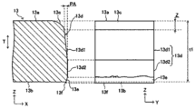
- FIG. 2 is an explanatory diagram showing a first aspect of a cut end portion in region A of FIG. 1 .
- 2 is an explanatory diagram showing a second aspect of the cut end portion in region A of FIG. 1 .
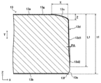
- FIG. FIG. 3 is a detailed cross-sectional view of the cut end of FIG. 2 .
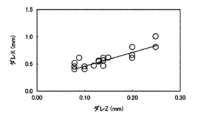
- 13 is a graph showing an example of the relationship between sagging Z and sagging X.
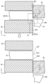
- 1 is an explanatory diagram showing a method for manufacturing a metal processed product according to an embodiment of the present invention
- FIG. 1 is an explanatory diagram showing a method for manufacturing a metal processed product according to an embodiment of the present invention
- FIG. 7 is an explanatory diagram showing a first die and a first punch used in the half-cutting step of FIG. 6 .
- FIG. 7 is an explanatory diagram showing a second die and a second punch used in the finish cutting step of FIG. 6 .
- FIG. 9 is an explanatory diagram showing an enlarged view of region B in FIG. 8 .
- FIG. 7 is an explanatory diagram showing a second aspect of the first die and the first punch used in the half-cutting step of FIG. 6 .
- FIG. 7 is an explanatory diagram showing a second embodiment of a second die and a second punch used in the finish cutting step of FIG. 6 .
- FIG. 1 is an explanatory diagram showing a ductile burr that may occur during finish cutting.
- FIG. 1 is an explanatory diagram showing a ductile burr that may occur during finish cutting.
- FIG. 11 is an explanatory diagram showing an uncut defect that may occur in finish cutting.
- FIG. 2 is a perspective view showing an example of a processed product.
- FIG. 11 is a perspective view showing another example of a processed product.
- FIG. 11 is a perspective view showing another example of a processed product.
- FIG. 15 is a schematic diagram showing an example of a cutting die for manufacturing the processed product of FIG. 14 .
- 19 is a schematic diagram showing a state in which a material has been punched using the cutting die of FIG. 18.
- FIG. FIG. 11 is a perspective view showing another example of a processed product.
- 13 is a graph showing the relationship between the ratio (C 32-42 /t2) ⁇ 100 of the clearance C 32-42 between the second die and the second punch to the remaining sheet thickness of the half-cut portion when the radius of curvature R D2 is 1.00 mm or more, and the remaining sheet thickness t2.
- 13 is a graph showing the relationship between the ratio (C 32-42 /t2) ⁇ 100 of the clearance C 32-42 between the second die and the second punch to the remaining sheet thickness t2 of the half-cut portion when the radius of curvature R D2 is less than 1.00 mm, and the remaining sheet thickness t2.
- Fig. 1 is a perspective view showing an example of a metal processed product 1 manufactured by a manufacturing method for a metal processed product 1 according to an embodiment of the present invention.
- the metal processed product 1 shown in Fig. 1 is a motor case made of a plated metal sheet having a plating layer on its surface.
- the metal processed product 1 in this embodiment has a body portion 10, a protrusion portion 11, and a flange portion 12.
- the body 10 has a hollow cylindrical side wall 101 and a top wall 103 formed to cover one end of the side wall 101.
- the top wall 103 may be called something else, such as a bottom wall, depending on the orientation in which the metal processed product 1 is used.
- the cross-sectional shape of the body 10 of the metal processed product 1 shown in FIG. 1 in the XY plane (the transverse cross-sectional shape of the body 10) is a perfect circle, but the present invention is not limited to this example.
- the cross-sectional shape of the body 10 in the XY plane may be other shapes, such as an ellipse or a polygon.
- the protrusion 11 is a protruding body that protrudes from the top wall 103 to the outside in the central axis direction (Z direction) of the body 10. Note that the protrusion 11 does not necessarily have to be formed, and the top wall 103 may be flat.
- the flange portion 12 is a plate portion that extends from an end of the body portion 10 (i.e., the other end of the side wall 101) toward the outside in the radial direction (X and Y directions) of the body portion 10.
- the shape of the flange portion 12 is arbitrary.
- the flange portion 12 in this embodiment extends in the radial direction of the body portion 10 over the entire circumferential area of the body portion 10.
- the flange portion 12 has a plurality of screw holes 121 spaced apart from each other in the circumferential direction of the body portion 10. Screws 123 are inserted into the screw holes 121.
- the metal processed product 1 can be fixed to an attachment object, such as a vehicle body, by fastening it to the attachment object using the screws 123.
- the flange portion 12 in this embodiment is formed by cutting a flange portion base body (flange portion base body 20 in FIG. 6) that has an outer diameter larger than the outer diameter of the flange portion 12 that will ultimately be formed in the metal processed product 1.
- the metal processed product 1 in this embodiment has a cut end portion 13 on the outer periphery of the flange portion 12. The cut end portion 13 is aligned along the sheet thickness direction of the plated metal sheet that is the material.
- Cutting processes include processes such as shearing, punching, and drilling.
- Cutting is a process in which the object to be cut is cut along a specified straight line or curve.
- Punching is a process in which a product is punched out of the object to be cut.
- Drilling is a process in which a non-product part is punched out of the object to be cut, resulting in a product with an opening.
- the flange portion 12 shown in Figure 1 can be obtained by punching out the flange portion base body.
- the base material of the plated metal sheet may be any metal, such as steel, copper, a copper alloy, aluminum, or an aluminum alloy.
- the plated metal sheet is a plated steel sheet.
- the manufacturing method of the metal processed product 1 according to the embodiment of the present invention described later is particularly suitable when the base material is steel. This is because steel rusts easily, and the advantage of imparting corrosion resistance is great.
- the plated steel sheet is, for example, a Zn-based plated steel sheet, an Al-based plated steel sheet, etc.
- the plated steel sheet is more preferably a Zn-based plated steel sheet.
- Zn-based plating has a sacrificial corrosion protection effect on the base material steel sheet. Therefore, it is possible to suppress corrosion from the exposed base material part of the end face of the cut end portion 13, and the corrosion resistance of the manufactured metal member can be further improved.
- Examples of Zn-based plating include hot-dip Zn zinc plating, alloyed hot-dip galvanizing, Zn-Ni plating, Zn-Al plating, Zn-Mg plating, Zn-Al-Mg plating, etc.
- the thickness of the plated metal sheet is not particularly limited.
- the thickness of the plated metal sheet can be, for example, 0.8 mm or more and 6.0 mm or less, more preferably 2.0 mm or more and 4.5 mm or less.
- a preferred lower limit of the plating weight is 30 g/ m2 .
- a more preferred lower limit of the plating weight is 45 g/ m2 .
- a preferred upper limit of the plating weight is 450 g/ m2 .
- a more preferred upper limit of the plating weight is 190 g/ m2 .
- Figures 2 and 3 are explanatory diagrams showing the first and second aspects of the cut end 13 in region A in Figure 1.
- the left side of Figures 2 and 3 is a cross-sectional view of the cut end 13 in the ZX plane in Figure 1
- the right side of Figures 2 and 3 is a front view of the cut end 13 as viewed along the X direction in Figure 1.
- Figure 4 is a detailed cross-sectional view of the cut end 13 in Figure 2.
- Figure 5 is a graph showing an example of the relationship between sagging Z and sagging X.
- the plate thickness direction T of the cut end 13 is the same direction as the central axis direction (Z direction) of the metal processed product 1 shown in Figure 1.
- the plating layer 13g shown in Figure 4 is omitted.
- the cut end 13 has a sag 13c, a sheared surface 13d, and a burr 13f in the plate thickness direction T of the cut end 13 from the upper surface 13a side toward the lower surface 13b side.
- the cut end 13 may further have a fractured surface 13e between the sheared surface 13d and the burr 13f.
- the metal processed product 1 does not have a burr 13f, and the metal processed product 1 according to this embodiment may be a metal processed product 1 without a burr 13f.
- the upper surface 13a is the surface (pushed surface) into which the cutting edge of the cutting die (first die 31 and second die 32 in Figures 7 and 8, etc.) is pressed when cutting the flange portion body.
- the lower surface 13b is the surface from which the cutting edge of the cutting die emerges when cutting the flange portion body.
- the sagging 13c is a portion of the flange body surface deformed by a tensile force acting on the surface of the flange body (the plated metal sheet material) when the cutting edge of the cutting die is pressed into the flange body.
- the sagging 13c typically appears on the cut end 13 as a smooth surface with a curvature.
- the dimension of the sagging 13c in the thickness direction T of the cut end 13 is referred to as "sagging Z”
- the dimension of the sagging 13c in the planar direction perpendicular to the thickness direction T is referred to as "sagging X”.
- the sheared surface 13d is the surface where the flange portion body has been sheared by the cutting edge of the cutting die.
- the sheared surface 13d is adjacent to the sag 13c in the plate thickness direction T of the cut end 13.
- the sheared surface 13d typically appears as a smooth surface at the cut end 13.
- the sheared surface 13d may have a metallic luster because it is created when the cutting die comes into contact with the workpiece and then a compressive (pressure) force is applied, causing it to bite into the workpiece and rub against the side of the cutting die.
- the sheared surface 13d may have fine streak-like sliding marks in the plate thickness direction T.
- the fracture surface 13e is a surface formed by the intersection of cracks that have developed in the flange portion body from the cutting edge of the cutting die.
- the fracture surface 13e may be adjacent to the shear surface 13d in the plate thickness direction T of the flange portion 12.
- the fracture surface 13e typically appears at the cut end 13 as a dull, rough surface.
- the fracture surface 13e may have an inclination that corresponds to the gap (clearance) of the cutting die.
- the burrs 13f are areas where the flange body is stretched or torn off when the fracture surface 13e is formed.
- the burrs 13f are adjacent to the fracture surface 13e in the plate thickness direction T of the flange 12.
- methods for identifying the sagging 13c, shear surface 13d, fracture surface 13e, and burrs 13f include, for example, observing and measuring the shape profile of the cut end 13 from the outside using a microscope or a contrast tracer based on the above characteristics.
- the shear surface 13d has a first shear surface 13d1 that is continuous with the sag 13c in the plate thickness direction T, and a second shear surface 13d2 that is continuous with the first shear surface 13d1.
- the lower end of the second shear surface 13d2 may be continuous with the fracture surface 13e.
- the second shear surface 13d2 is formed protruding from the first shear surface 13d1 in a direction perpendicular to the plate thickness direction T (X-axis direction in the figure), and the protruding amount PA of the second shear surface 13d2 in a direction perpendicular to the first shear surface 13d1 is more than 0 mm and 0.25 mm or less.
- a step 13d3 having a height of more than 0 mm and 0.25 mm or less may be formed between the first shear surface 13d1 and the second shear surface 13d2.
- the protrusion amount PA may be 0.20 mm or less, or 0.15 mm or less.
- Fig. 2 shows a state in which the first shear surface 13d1 extends substantially in the plate thickness direction T. This shows a state that tends to occur when the constraint by the first plate holder 51 (see Fig. 7, etc.) is sufficiently strong during the half-cutting process described below, or when the clearance C 31-41 during the half-cutting process is large (even among the negative clearances,
- Fig. 3 shows a state in which the first shear surface 13d1 extends at an angle to the plate thickness direction T.
- the left side of the flange portion 12 in Figure 7 will jump up due to the compressive stress during the half-cutting process, and in the finish-cutting process which is performed after the half-cutting process, the flange portion 12 is pressed down by the second plate holder 52 to be flattened before the finish-cutting is performed, so that the first shear surface 13d1 tends to be inclined with respect to the plate thickness direction T.
- the protrusion amount PA may be the maximum distance between the end face of the first shearing surface 13d1 and the end face of the second shearing surface 13d2 in a direction perpendicular to the thickness direction T. In an embodiment in which the first shearing surface 13d1 extends in the thickness direction T as in FIG. 2, the protrusion amount PA may be the distance between the end face of the first shearing surface 13d1 and the end face of the second shearing surface 13d2 in a direction perpendicular to the thickness direction T. In an embodiment in which the first shearing surface 13d1 extends at an angle to the thickness direction T as in FIG.
- the protrusion amount PA may be the distance between the upper end position of the first shearing surface 13d1 (the connection position between the sag 13c and the first shearing surface 13d1) and the end face of the second shearing surface 13d2 in a direction perpendicular to the thickness direction T.
- the plating layer 13g wraps around the sheared surface 13d from the upper surface 13a of the cut end portion 13.
- the plating layer 13g is stretched by the cutting die and wraps around the sheared surface 13d. This wrapping around of the plating layer 13g causes at least a portion of the sheared surface 13d to be covered with the plating layer 13g, making it possible to suppress the occurrence of red rust in the portion covered with the plating layer 13g.
- the sacrificial anticorrosive effect of the Zn-based plating layer can also suppress the occurrence of red rust in the vicinity of the portion covered with the plating layer 13g.
- the first shear surface 13d1 is generated in the half-cutting process
- the second shear surface 13d2 is generated in the finish cutting process after the half-cutting process.
- the finish cutting is performed with a positive clearance, so the compressive stress acting on the cutting edge of the second die 32 used in the finish cutting is small. For this reason, less of the plating layer 13g wraps around the second shear surface 13d2 than the first shear surface 13d1.
- the length L1 of the plating layer 13g covering at least a part of the sagging 13c and the sheared surface 13d from the upper surface 13a of the cut end 13 is 0.80 times or more the thickness t1 of the cut end 13 of the metal processed product 1. That is, the ratio L1/t1 of the plating component remaining length L where the sheared surface 13d is covered by the plating layer 13g on the surface of the plated metal plate and the thickness t1 of the cut end 13 is 0.80 or more. L1/t1 may be 0.85 or more.
- the length L1 of the plating layer 13g or the plating component remaining length L1 can also be said to be the distance between the upper surface 13a of the cut end 13 and the lower end of the plating layer 13g in the thickness direction T of the cut end 13.
- the thickness t1 of the cut end 13 can also be said to be the distance between the upper surface 13a and the lower surface 13b of the cut end 13 in the thickness direction T of the cut end 13. More specifically, the thickness t1 of the cut end 13 may be the distance between the upper surface 13a and the lower surface 13b at a position not affected by the sagging 13c (a position sufficiently distant from the outer edge of the cut end 13).
- the thickness t1 of the cut end 13 is equal to the thickness of the flange portion 12 shown in FIG. 1.
- the ratio Z/t1 of the length Z of the sagging 13c in the thickness direction T to the thickness t1 of the cut end 13 is greater than 0 and less than 0.10.
- Sagging Z and sagging X are correlated with each other. Therefore, in terms of sagging Z, which is easy to measure, it is preferable that the ratio Z/t1 is less than 0.10.
- the thickness t1 of the cut end 13 is also equal to the thickness of the flange portion body 20. It is preferable that the sagging Z is small, and the ratio Z/t1 may be less than 0.08, less than 0.06, or less than 0.04.
- Figure 5 shows an example of the relationship between sagging Z and sagging X of the cut end 13 when punching is performed in a single process.
- Figure 5 shows the relationship between sagging Z and sagging X of the cut end 13 of the product when punching is performed by giving the cutting edge of the cutting die that is pressed into the flange body a radius of curvature of 0.01 to 0.30 in relation to the plate thickness of the flange body and setting the clearance of the cutting die to 0.01 to 0.20 times the plate thickness.
- the sagging X that appears in the planar direction is approximately 3 to 4 times the size of the sagging Z in the plate thickness direction.
- the length of the burrs 13f generated on the lower side of the cut end portion 13 of the metal workpiece 1 may be less than 0.2 mm.
- the burrs 13f can cause dents, electrical short circuits, etc.
- the length of the burrs 13f is less than 0.1 mm.
- the length of the burrs 13f is 0 mm, i.e., no burrs 13f are present on the metal workpiece 1.
- the plated steel sheet is cut in two steps, a semi-cutting step and a finish-cutting step, rather than being cut in a single step. This allows more of the plated layer 13g to wrap around the sheared surface 13d while preventing the sagging 13c of the cut end 13 from becoming too large.
- the processed product manufacturing method according to this embodiment will be described below.
- Fig. 6 is an explanatory diagram showing a manufacturing method of the metal processed product 1 according to the embodiment of the present invention.
- the manufacturing method of the metal processed product 1 according to the embodiment of the present invention includes a preparation step, a semi-cutting step, and a finish cutting step.
- the preparation process is a process of preparing the first body 2.
- the first body 2 can be obtained by performing forming processing such as drawing on a flat plated metal plate. That is, the first body 2 is made of a plated metal plate, like the metal processed product 1.
- the first body 2 has a flange portion body 20 having an outer diameter larger than the flange portion 12 shown in FIG. 1.
- the flange portion body 20 may have a circular or non-circular outer shape in a plan view.
- the first body 2 may have a shape similar to that of the metal processed product 1 except for the flange portion body 20.
- the preparation process does not have to involve forming processing on the plated metal strip.
- a body processed by a third party by some method may be obtained.
- the flange portion body 20 in this embodiment constitutes the flat cut portion including the portion that will become the cut end portion 13.
- the half-cutting process is a process in which the first body 2 is half-cut in the plate thickness direction to form a half-cut portion.
- the flange portion body 20 (the portion to be cut) is half-cut.
- Half-cutting is a process in which the flange portion body 20 is cut to a midpoint in the plate thickness direction of the flange portion body 20.
- the smooth surface smoothed by the side of the die used for half-cutting becomes the first shear surface 13d1.
- the finish cutting process is a process in which the half-cut portion is finish-cut from the same direction as the half-cut to obtain a metal processed product 1 having a cut end 13.
- the removed portion 20a of the flange portion body 20 is cut and separated from the flange portion body 20.
- the flange portion 12 is formed by cutting the removed portion 20a.
- the smooth surface smoothed by the side of the die used for the finish cutting becomes the second shear surface 13d2. That is, in the manufacturing method of the metal processed product 1 according to this embodiment, the metal processed product 1 is obtained from the first body 2 prepared in the preparation process through the half-cutting process and the finish cutting process.
- the screw holes 121 of the metal processed product 1 shown in FIG. 1 may be formed in the flange portion body 20 at the stage of the first body 2, or may be formed in the flange portion 12 after the finish cutting process.
- the flange portion body 20 is machined using a die and a punch. Details of the half-cutting process and the finish-cutting process are described below.
- the cutting edges of the die and punch are sometimes referred to as "shoulders.”
- the die used to obtain the metal processed product 1 will be referred to as the die on the pushing side and the die on the side being pushed in as the punch.
- the die on the pushing side may be located above or below the first body 2.
- the die on the pushing side will also be referred to as the die and the die on the side being pushed in as the punch.
- the metal processed product 1 shown in FIG. 2 was cut using the upper die as the pushing side die. If the lower die is the pushing side die, that is, if the lower die is the die, the cut end 13 of the metal processed product 1 will have the sag 13c located at the bottom of the cut end 13, as opposed to FIG. 2, and the shear surface 13d will be formed above it.
- the upper surface 13a of the cut end 13 is defined as the surface on the side where the cutting edge of the die is pressed in during cutting of the flange body 20, i.e., the surface on the side where the sag 13c is located.
- the lower surface 13b of the cut end 13 is defined as the surface on the side where the cutting edge of the die comes out during cutting of the flange body 20.
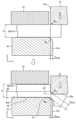
- Fig. 7 is an explanatory diagram showing the first die 31 and the first punch 41 used in the half-cutting step of Fig. 6.
- the upper side of Fig. 7 shows the state immediately before the half-cutting process, and the lower side of Fig. 7 shows the state immediately after the half-cutting process.
- the first body 2 is half-cut in the plate thickness direction using the first die 31 and the first punch 41 to form the half-cut portion 21.
- FIG. 7 shows one embodiment of the half-cutting process in which the flange portion body 20 of the first body 2 clamped between the first punch 41 and the first plate holder 51 is half-cut (half-punched).
- the first die 31 constitutes a cutting mold that is pressed into the flange portion body 20 during half-cutting.
- the mold that presses the portion of the flange portion body 20 that will become the flange portion 12 is the first punch 41
- the mold that presses the removed portion 20a is the first die 31.
- the clearance C 31-41 (mm) between the first die 31 and the first punch 41 is a negative clearance.
- the clearance C 31-41 represents the gap between the first die 31 and the first punch 41, and is specifically represented by the distance between the side surface 31a of the first die 31 and the side surface 41a of the first punch 41, as shown in FIG. 7.
- the clearance in a state where there is no clearance i.e., when C 31-41 is zero
- the clearance in a state where the first die 31 and the first punch 41 are separated from each other as viewed from the pushing direction of the first die 31 i.e., the plate thickness direction of the flange portion 12, the Z direction
- the clearance in a state where the first die 31 and the first punch 41 partially overlap each other is called a negative clearance.
- the clearance between the die and the punch is represented by a positive value for the positive clearance and a negative clearance for the negative clearance.
- the first die 31 and the first punch 41 for semi-cutting the first body 2 are arranged so that the first die 31 and the first punch 41 partially overlap when viewed from the pushing direction of the first die 31.
- the clearance C 31-41 is a positive clearance
- cracks generated from the cutting edges of the first die 31 and the first punch 41 may meet as in a one-time punching process, and the removed portion 20a may be completely cut off from the flange portion body 20.
- the sagging 13c of the cut end portion 13 will increase.
- the clearance C 31-41 a negative clearance, a large hydrostatic stress occurs in the region sandwiched between the first die 31 and the first punch 41. Therefore, the ratio of the tensile stress occurring between the material that will become scrap (i.e., the removed portion 20a) after cutting and the flange material that will become the flange portion 12 in the stress occurring when the first die 31 is pressed into the flange portion element 20 decreases. As a result, the material that contacts the tip of the blade of the first die 31 that will become scrap after cutting is more likely to flow from the tip of the blade of the first die 31 to the side 31a of the first die 31, and the wrapping of the plating layer 13g around the sheared surface 13d can be increased.
- the clearance C 31-41 (mm) between the first die 31 and the first punch 41 satisfies the following formula (a1). -0.35 ⁇ t1 ⁇ C 31-41 ⁇ -0.0125 ⁇ t1...(a1)
- t1 is the plate thickness (mm) of the portion to be cut in half of the first body 2.
- the portion to be cut in half of the first body 2 is the flange portion body 20.
- the clearance C 31-41 is ⁇ 0.0125 times or less the plate thickness t1 of the flange portion element 20, a large hydrostatic stress is generated in the region sandwiched by the first die 31 and the first punch 41, and the proportion of tensile stress is reduced. As a result, cracks are generated during half-cutting, causing complete cutting, and large fracture surfaces are prevented from being generated, and the removal portion 20a is prevented from being completely cut from the flange portion element 20 in the half-cutting process.
- the clearance C 31-41 is ⁇ 0.35 times or more the plate thickness t1 of the flange portion element 20, the forming load required for half-cutting does not increase and does not exceed the press capacity.
- the clearance C 31-41 is ⁇ 0.10 times or less or ⁇ 0.15 times or less the plate thickness t1 of the flange portion element 20.
- the clearance C 31-41 may be set to be ⁇ 0.30 times or more, or ⁇ 0.25 times or more, the plate thickness t 1 of the flange portion element 20 .
- the cutting edge of the first die 31 is rounded with a radius of curvature R D1 (mm) as shown in FIG. 7, and it is preferable that the radius of curvature R D1 (mm) of the cutting edge of the first die 31 satisfies the following formula (a2). 0.10 ⁇ t1 ⁇ R D1 ⁇ 1.50 (a2)
- the cutting edge of the first punch 41 is formed into an R-shape having a radius of curvature R P1 (mm) as shown in FIG. 7, and it is preferable that the radius of curvature R P1 (mm) of the cutting edge of the first punch 41 satisfies the following formula (a3). 0.10 ⁇ t1 ⁇ R P1 ⁇ 3.00 (a3)
- the radii of curvature R D1 and R P1 are 0.10 times or more the plate thickness t1
- a large hydrostatic stress is generated under a negative clearance without scraping off the plating layer 13g, and the material to be scrapped (i.e., the removed portion 20a) directly below the first die 31 can flow from the cutting edge of the first die 31 to the side surface 31a of the first die 31.
- R D1 is 0.10 times or more the plate thickness t1
- the first die 31 can be pushed deeper into the flange portion element 20, so that the material to be scrapped (i.e., the removed portion 20a) directly below the first die can flow from the cutting edge of the first die 31 to the side surface 31a of the first die 31.
- the proportion of the tensile stress generated between the material to be scraped after cutting and the flange material to be the flange portion 12 in the stress generated when the first die 31 is pushed into the flange portion element 20 decreases.
- the plating layer 13g can be wrapped around the shear surface 13d.
- the amount of flange portion body 20 cut in the half-cutting process can be increased compared to when only one of the cutting edges of the first die 31 or the first punch 41 is R-shaped.
- the remaining plate thickness t2 (mm) of the half-cut portion 21 of the first body 2 can be reduced compared to when only one of the cutting edges of the first die 31 or the first punch 41 is R-shaped.
- the remaining thickness t2 of the half-cut portion 21 of the first body 2 corresponds to the distance in the pressing direction of the first die 31 between the connection position of the cutting edge of the first die 31 and the side surface 31a and the upper surface 41b of the first punch 41 that contacts the lower surface 2b of the first body 2 when the first die 31 is pressed down to the bottom dead center as shown in the lower part of Figure 7, and can also be said to be the remaining thickness of the removed portion 20a in the half-cut portion 21.
- the cutting edge of the first die 31 will come into contact with the cutting edge of the first punch 41 if the pushing amount D of the first die 31 is set to be greater than or equal to the thickness t1 of the flange portion 12. In this case, the pushing amount D of the first die 31 cannot be set to be greater than or equal to the thickness t1 of the flange portion 12.
- the pushing amount D is the amount of movement of the first die 31 from the position where the first die 31 contacts the top surface of the flange portion body 20 of the first body 2 to the position where the pushing of the first die 31 stops (hereinafter, this position is also referred to as the "bottom dead center"), as shown in FIG. 7.
- the cutting edges of the first die 31 and the first punch 41 are R-shaped, the amount by which the first die 31 can be pushed in until the cutting edge of the first die 31 contacts the cutting edge of the first punch 41 increases, as shown in FIG. 7. Therefore, by making both the cutting edges of the first die 31 and the first punch 41 R-shaped, the pushing amount D of the first die 31 can be made equal to or greater than the plate thickness t1 of the flange portion 12, making it possible to increase the amount of cutting of the flange portion body 20 in half-cutting, and increasing the proportion of the sheared surface 13d in the cut end portion 13.
- the plating layer 13g wrap around the sheared surface 13d more, and the proportion of the cut end portion 13 covered by the plating layer 13g can be increased.
- the remaining plate thickness t2 is reduced, so that the amount of cutting in the finish cutting process is reduced, and it is possible to avoid a state in which no plating layer remains in a part of the finish-cut portion.
- the remaining plate thickness t2 (mm) of the half-cut portion 21 satisfies the following formula (a4). 0.20 ⁇ t2 ⁇ 1.80...(a4)
- the plating layer 13g can be sufficiently wrapped around the sheared surface 13d in the subsequent finish cutting process. This improves the corrosion resistance of the cut surface.
- the upper limit of the remaining sheet thickness t2 is preferably 1.40 mm, and more preferably 1.30 mm.
- the remaining plate thickness t2 is 0.20 mm or more, it is possible to avoid a portion being cut off during the semi-cutting process, or the occurrence of a partial giant burr due to partial non-cutting after the finish cutting process.
- the distance C P1-D1 between the first die 31 and the first punch 41 at the bottom dead center can be secured, and it is possible to avoid the occurrence of cracks during the semi-cutting process, which results in partial complete cutting.
- the distance C P1-D1 is the minimum value of the distance between the first die 31 and the first punch 41 at the bottom dead center.
- the lower limit of the remaining plate thickness t2 is preferably 0.40 mm, and more preferably 0.50 mm.
- Fig. 8 is an explanatory diagram showing the second die 32 and the second punch 42 used in the finish cutting step of Fig. 6, and Fig. 9 is an explanatory diagram showing an enlarged view of region B of Fig. 8.
- the upper side of Fig. 8 shows the state immediately before the finish cutting process, and the lower side of Fig. 8 shows the state immediately after the finish cutting process.
- the flange portion body 20 having the half-cut portion 21 is finish-cut using the second die 32 and the second punch 42.
- FIG. 8 shows one mode of finish cutting in which the flange portion 12 is punched out from the flange portion body 20 held by the second punch 42 and the second plate holder 52.
- the second die 32 constitutes a cutting die that is pressed into the flange portion body 20 during finish cutting.
- the die that presses the portion of the flange portion body 20 that will become the flange portion 12 is the second punch 42, and the die that presses the removed portion 20a is the second die 32.
- the finish cutting in this embodiment is performed from the same direction as the half cutting. That is, when the first die 31 is pressed into the flange portion body 20 from the top side of the flange portion body 20 in the half cutting as shown in FIG. 7, the second die 32 is also pressed into the flange portion body 20 from the top side of the flange portion body 20 in the finish cutting as shown in FIG. 8. This separates the removed portion 20a from the flange portion body 20, and obtains the metal processed product 1 having the flange portion 12 and the cut end portion 13.
- the clearance C32-42 (mm) between the second die 32 and the second punch 42 is a positive clearance.
- the clearance C32-42 is expressed as the distance between the side surface 32a of the second die 32 and the side surface 42a of the second punch 42.
- the clearance when the second die 32 and the second punch 42 are separated from each other is called a positive clearance
- the clearance when the second die 32 and the second punch 42 are partially overlapped is called a negative clearance.
- the change in the clearance C31-41 (mm) between the first die 31 and the first punch 41 in the semi-cutting process to the clearance C32-42 (mm) between the second die 32 and the second punch 42 is carried out by changing the side position from the first die 31 to the second die 32, and the changed distance Md (mm) from the side position of the first die 31 to the side position of the second die 32 satisfies the following formula (b1). Md ⁇ 0.25...(b1)
- the change in side position from the first die 31 to the second die 32 may be synonymous with the change in diameter from the first die 31 to the second die 32.
- the relationship between the diameter D 31 of the first die 31 and the diameter D 32 of the second die 32 may satisfy the following formula (b1)′. 0.5mm ⁇
- the inner diameter of the second die 32 is set to be equal to or larger than the inner diameter of the first die 31, and when the cut end 13 is formed on the inner periphery of the metal workpiece 1, the outer diameter of the second die 32 is set to be equal to or smaller than the outer diameter of the first die 31.
- the diameters D 31 and D 32 in formula (b1)' refer to the inner diameters of the first die 31 and the second die 32 when the cut end 13 is formed on the outer periphery of the metal workpiece 1, and refer to the outer diameters of the first die 31 and the second die 32 when the cut end 13 is formed on the inner periphery of the metal workpiece 1.
- Changing the clearance by changing the side position from the first die 31 to the second die 32 can be said to mean that the position of the side 42a of the second punch 42 is set to the position of the side 31a of the first die 31 at the time of half-cutting (the position of the first shear surface 13d1), and finish cutting is performed in a state where the side 32a of the second die 32 is separated from the first shear surface 13d1 by a clearance C32-42 (mm).
- FIG. 9A shows a state in which the clearance is changed by changing the side position from the first die 31 to the second die 32, and the side 32a of the second die 32 is separated from the first shearing surface 13d1 by a clearance C 32-42 (mm).
- FIG. 9B shows a state in which the clearance is changed by changing the side position from the first punch 41 to the second punch 42, and the side 32a of the second die 32 is in contact with the first shearing surface 13d1.
- FIG. 9B can also be said to show a state in which the diameter D 32 of the second die 32 is not changed from the diameter D 31 of the first die 31, and the positional relationship between the second die 32 and the first element body 2 is the same as the positional relationship between the first die 31 and the first element body 2.
- the clearance C 31-41 (mm) between the first die 31 and the first punch 41 is set to a negative clearance, so that when the first die 31 is pressed to the bottom dead center, the location where the first die 31 and the first punch 41 come closest to each other, i.e., the location where the thickness of the half-cut portion 21 is the thinnest, is located between the extension of the side surface 31a of the first die 31 and the extension of the side surface 41a of the first punch 41.
- the thickness t3 of the half-cut portion 21 on the extension of the side surface 32a of the second die 32 becomes thinner than when the side surface 32a of the second die 32 is in contact with the first shearing surface 13d1 as shown in Fig. 9(b).
- the thickness t3 corresponds to the length for performing the finish cut, and the thinner the thickness t3, the longer the first sheared surface 13d1 can be left, and the longer the remaining length L of the plating component can be.
- the cutting may not be completed partially in the finish cutting process, and an uncut portion may occur. Even if the cutting can be completed, an excessive step 13d3 is likely to occur on the end face of the cut end portion 13 after the finish cutting.
- the change distance Md is preferably 0.088 mm or less, and more preferably 0.063 mm or less.
- the absolute value of the difference is preferably 0.175 mm or less, and more preferably 0.125 mm or less.
- the cutting edge of the second die 32 is R-shaped with a predetermined radius of curvature R D2 (mm). As shown in Fig. 15, the second die 32 is pressed into the portion of the flange portion body 20 where the finish cutting is performed, so the cutting edge of the second die 32 is R-shaped with the radius of curvature R D2 . It is preferable that the radius of curvature R D2 (mm) satisfies the following formula (b2). 0.20 ⁇ R D2 ⁇ 1.20 (b2)
- R D2 is preferably 0.20 mm or more.
- the lower limit of R D2 is more preferably 0.25 mm, and even more preferably 0.30 mm.
- R D2 is preferably 1.20 mm or less.
- the upper limit of R D2 is more preferably 1.00 mm, and even more preferably 0.80 mm.
- the cutting edge of the second punch 42 is angular and not rounded as shown in FIG. 8.
- the cutting edge of the second punch 42 may have a radius of curvature of less than 0.25 mm, less than 0.15 mm, less than 0.10 mm, or less than 0.05 mm.
- the radius of curvature of the cutting edge of the second punch 42 may be less than 0.10 times the plate thickness t1 of the flange portion body 20 of the first body 2, and may be less than 0.06 times, less than 0.04 times, or less than 0.02 times as necessary.
- Figure 10 is an explanatory diagram showing a second aspect of the first die 31 and the first punch 41 used in the half-cutting process of Figure 6, and Figure 11 is an explanatory diagram showing a second aspect of the second die 32 and the second punch 42 used in the finish-cutting process of Figure 6.
- Figure 10 shows a state of half-cutting where the indentation amount D is smaller than that in Figure 7.
- the smaller indentation amount D increases the remaining plate thickness t2 to be cut in the finish cut.
- the inventors conducted experiments in which the plate thickness t1 of the flange portion 12 on which the cut end 13 is formed, the cutting conditions, and the surface treatment conditions were varied over various ranges, and investigated the occurrence of ductile burrs 14 (see FIG. 12) and uncut defects 15 (see FIG. 13) during finish cutting, as well as the remaining length L of the plating component and the step 13d3 of the cut end 13.
- the ductile burr 14 is a burr that is not cut during the finish cutting and is stretched thin, and tends to occur when the clearance C 32-42 between the second die 32 and the second punch 42 during the finish cutting is too small compared to the remaining thickness t2 of the half-cut portion 21 formed by the half-cutting.
- the uncut defect 15 is a partial giant burr that occurs due to partial uncutting, and tends to occur when the clearance C 32-42 between the second die 32 and the second punch 42 during the finish cutting is too large compared to the remaining thickness t2 of the half-cut portion 21 formed by the half-cutting.
- the size of the step 13d3 of the cut end 13 corresponds to the protrusion amount PA (see FIG. 2) of the second shear plane 13d2 in a direction perpendicular to the first shear plane 13d1.
- the ratio (C 32-42 /t2) ⁇ 100(%) satisfies the following formulas (b3-1) and (b3-2) when the radius of curvature R D2 is 1.00 mm or more.
- (b3-1) (C 32-42 /t2) ⁇ 100 ⁇ 7.8 ⁇ t2 2 -0.6 ⁇ t2+18.0 ... (b3-2)
- the ratio (C 32-42 /t2) ⁇ 100(%) satisfies the following expressions (b3-4) and (b3-2).
- (b3-4) (C 32-42 /t2) ⁇ 100 ⁇ 7.8 ⁇ t2 2 -0.6 ⁇ t2+18.0...(b3-2)
- the radius of curvature R of the second die 32 in this embodiment is 0.20 mm or more and 1.20 mm or less.
- the radius of curvature R is 1.00 mm or more, this means that the radius of curvature R is 1.00 mm or more and 1.20 mm or less, and when the radius of curvature R is less than 1.00 mm, this means that the radius of curvature R is 0.20 mm or more and less than 1.00 mm.
- the metal processed product 1 is a motor case as shown in Fig. 1
- the metal processed product 1 manufactured by the processed product manufacturing method according to the present embodiment may be any article made of a plated metal sheet and having a cut end portion 13.
- the metal processed product 1 include plate materials, drawn products having flange portions 12, burred products having flange portions 12, bulged products having flange portions 12, bent products, punched products such as various washers, plates, gears, and springs.
- the metal processed product 1 may be, for example, a circular flat washer 900 as shown in FIG. 14.
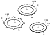
- the metal processed product 1 may also be, for example, a flat washer 910A, 910B, 910C having teeth 911 as shown in FIG. 15.
- the metal processed product 1 may be, for example, a wavy circular disc spring 920 as shown in FIG. 16.
- the disc spring 920 in FIG. 16 may be manufactured by processing, for example, the flat washer 900 shown in FIG. 14 into a wavy shape.
- the metal processed product 1 may be, for example, a disc spring 930 having teeth 931 as shown in FIG. 17.
- the metal workpiece 1 is an annular plate member such as those shown in Figures 14 to 17, its outer and inner peripheries become the cut ends 13.
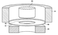
- FIG. 18 is a schematic diagram showing an example of a cutting die for processing the flat washer 900.
- FIG. 19 is a schematic diagram showing the state after the blank 9 has been punched using the cutting die of FIG. 18.
- the cutting die shown in FIG. 18 is a die for manufacturing an annular metal workpiece 90 such as a flat washer 900, and has a hollow cylindrical die (hereinafter referred to as the "outer die") 61, a cylindrical die (hereinafter referred to as the “inner die”) 63, and a hollow cylindrical punch 65 that supports a disk-shaped blank 9 (see FIG. 19).
- the outer die 61 and the inner die 63 are arranged opposite the punch 65, and the blank 9 is cut by pressing the outer die 61 and the inner die 63 into the blank 9 supported by the punch 65.
- the inner diameter of the outer die 61 corresponds to the outer diameter of the metal workpiece 90
- the outer diameter of the inner die 63 corresponds to the inner diameter of the metal workpiece 90.
- the cutting edge of the inner peripheral surface of the outer die 61 and the cutting edge of the outer peripheral surface of the inner die 63 have an R shape with a radius of curvature.
- the edges of the inner peripheral surface and the outer peripheral surface of the punch 65 do not have an R shape.
- the metal workpiece 1 may be, for example, a disk-shaped plate 940 as shown in FIG. 20.
- the inventors produced a number of processed product samples by varying the conditions for the semi-cutting and finish-cutting processes over a variety of ranges, as shown in Tables 1 and 2 below.
- a flat Zn-6%Al-3%Mg (by mass) alloy-plated steel plate with a thickness of 3.2 mm was used as the first element 2 (plated metal plate).
- the plating coverage of the steel plate was 90 g/ m2 (one side).
- the first blank 2 was subjected to a semi-cutting step by the method shown in FIG. 7 or FIG. 10.
- the first die 31 was pressed into the first blank 2 held by the first punch 41 and the first plate holder 51, thereby performing the semi-cutting process.
- the first die 31 was annular with a circular hole having an inner diameter of 85.00 mm.
- the first punch 41 was cylindrical so as to be insertable into the circular hole of the first die 31.
- the outer diameter of the first punch 41 was changed according to the clearance C 31-41 shown in Table 1.
- the cutting edges of the first die 31 and the first punch 41 were R-shaped with the radii of curvature R D1 and R P1 shown in Table 1.
- the pressing amount D of the first die 31 and the distance C PD between the first die 31 and the first punch 41 at the bottom dead center were as shown in Table 1.
- the first blank 2 after the half-cutting step was subjected to a finish cutting step by the method shown in FIG. 8 or FIG. 11 to obtain a processed sample.
- the second die 32 was pressed into the first blank 2 held by the second punch 42 and the second plate holder 52 to perform the finish cutting process.
- the second die 32 was an annular body having a circular hole with an inner diameter shown in Table 2.
- the second punch 42 was cylindrical so that it could be inserted into the circular hole of the second die 32.
- the second die 32 used had an inner diameter that was basically changed depending on the clearance. However, in Comparative Example 2, a die having an inner diameter of 85.00 mm, the same as the first die 31, was used.
- the outer diameter of the second punch 42 was basically 85.00 mm.
- the outer diameter of the second punch 42 was 84.66 mm.
- the cutting edge of the second die 32 was R-shaped with a radius of curvature R D2 shown in Table 2.
- the cutting edge of the second punch 42 was square with no roundness.
- the ratio Z/t1 of the length Z of the sagging 13c in the thickness direction T to the thickness t1 of the cut end 13, the ratio Z/t1 of the length X of the sagging 13c in the planar direction perpendicular to the thickness direction T to the thickness t1 of the cut end 13, the length (mm) of the fracture surface 13e in the thickness direction T, the ratio L/t1 of the remaining length L of the plating component to the thickness t1 of the cut end 13, and the protrusion amount PA (mm) of the second shear surface 13d2 relative to the first shear surface 13d1 were investigated.
- end sagging evaluation, ductile burr evaluation, the presence or absence of uncut defects, and step evaluation were performed for each processed product sample to investigate the number of days for red rust generation in the atmospheric exposure test. The results are shown in Table 3.
- a circle (o) indicates that the sagging Z length to sheet thickness ratio (Z/t1) is less than 0.10.
- a circle (o) indicates that the length of the ductile burr 14 is less than 0.2 mm
- a cross (X) indicates that the length of the ductile burr 14 is 0.2 mm or more.
- a circle (o) indicates that there are no uncut defects 15, and a cross (X) indicates that a huge burr has occurred due to an uncut defect 15.
- a circle (o) indicates that the protrusion amount PA (mm) of the second shear surface 13d2 relative to the first shear surface 13d1 is 0.25 mm or less
- a cross (X) indicates that the protrusion amount PA (mm) of the second shear surface 13d2 is more than 0.25 mm.
- Inventive Examples 1 to 22 are examples that satisfy the following processing conditions.
- the clearance C 31-41 (mm) between the first die 31 and the first punch 41 is set to a negative clearance
- the clearance C 32-42 (mm) between the second die 32 and the second punch 42 is set to a positive clearance
- the ratio of the clearance C 32-42 between the second die 32 and the second punch 42 to the remaining plate thickness t2 of the half-cut portion 21 (C 32-42 /t2) ⁇ 100(%) satisfies the
- the protrusion amount PA (mm) of the second shear surface 13d2 relative to the first shear surface 13d1 can be suppressed to 0.25 mm or less, but in Comparative Example 1, the protrusion amount PA (mm) of the second shear surface 13d2 relative to the first shear surface 13d1 is relatively large at 0.28. From these results, it can be seen that by satisfying the above formula (b1) and formula (b3-3), the step 13d3 of the cut end portion 13 can be suppressed to 0.25 mm or less.
- the change from the clearance C 31-41 (mm) between the first die 31 and the first punch 41 to the clearance C 32-42 (mm) between the second die 32 and the second punch 42 is made by changing the side position from the first punch 41 to the second punch 42, rather than by changing the side position from the first die 31 to the second die 32.
- the ratio of the remaining length of the plating component to the plate thickness (L/t1) is 0.70 or more, but in Comparative Example 2, it is less than 0.70.
- the clearance C 31-41 (mm) between the first die 31 and the first punch 41 satisfies the following formula (a1) and is close to the upper limit or lower limit. -0.35 ⁇ t1 ⁇ C 31-41 ⁇ -0.0125 ⁇ t1...(a1)
- t1 is the plate thickness (mm) of the portion to be cut in half of the first body.
- the semi-cutting step is as follows:
- the radius of curvature R D1 (mm) of the cutting edge of the first die 31 satisfies the following formula (a2): 0.10 ⁇ t1 ⁇ R D1 ⁇ 1.50 (a2)
- Inventive Examples 3 and 4 are examples close to the upper or lower limit of formula (a2)
- Inventive Examples 6 and 7 are examples close to the upper or lower limit of formula (a3).
- the radius of curvature R D1 of the cutting edge of the first die 31 does not satisfy the above formula (a2).
- the radius of curvature R P1 of the cutting edge of the first punch 41 does not satisfy the above formula (a3).
- the ratio L/t1 of the remaining length L of the coating component to the thickness t1 of the cut end 13 could be set to 0.80 or more. Also, as shown in Table 3, by setting the ratio L/t1 to 0.80 or more, good corrosion resistance can be obtained for 90 days or more until red rust occurs on the cut end 13.
- the remaining plate thickness t2 (mm) of the half-cut portion 21 satisfies the following formula (a4) and is close to the upper or lower limit of formula (a4). 0.20 ⁇ t2 ⁇ 1.80...(a4)
- Example 17 of the present invention is an example in which the remaining thickness t2 exceeds 1.80 mm.
- Reference Example 2 is an example in which the remaining thickness t2 is less than 0.20 mm.
- the ratio L/t1 of the remaining length L of the plating component to the thickness t1 of the cut end 13 can be made 0.80 or more, but in Example 17 of the present invention, the ratio L/t1 is less than 0.80.
- partial cutting occurred after half-cutting. From these results, it was found that it is preferable for the remaining thickness t2 (mm) to satisfy the above formula (a4).
- the cutting edge of the second die 32 is R-shaped with a radius of curvature R D2 (mm), and the radius of curvature R D2 (mm) satisfies the following formula (b2) and is close to the upper or lower limit of formula (b2). 0.20 ⁇ R D2 ⁇ 1.20 (b2)
- Inventive Example 18 is an example in which the radius of curvature R D2 is less than 0.20 mm.
- the ratio L/t1 of the remaining coating component length L to the sheet thickness t1 of the cut end portion 13 was 0.80 or more, but in Inventive Example 18, the ratio L/t1 was less than 0.80. From these results, it was found that it is preferable that the radius of curvature R D2 is 0.20 mm or more.
- Inventive Example 20 is an example in which the radius of curvature R exceeds 1.20 mm.
- the generation of ductile burrs 14 was suppressed, but ductile burrs 14 were generated in Inventive Example 20. From these results, it was found that it is preferable that the radius of curvature R is 1.20 mm or less.
- Examples 1 and 5 of the present invention are examples in which, when the radius of curvature R of the second die 32 is 1.00 mm or more, the ratio of the clearance C between the second die 32 and the second punch 42 to the remaining plate thickness t2 of the semi-cut portion 21 (C /t2) ⁇ 100 (%) satisfies the following formula (b3-1) and is close to the lower limit of formula (b3-1).
- Inventive Examples 16, 17, and 20 are examples in which the radius of curvature R D2 was 1.00 mm or more, and the ratio (C 32-42 /t2) ⁇ 100 (%) was below the lower limit of the above formula (b3-1).
- the occurrence of ductile burrs 14 was suppressed, but in Inventive Examples 16, 17, and 20, ductile burrs 14 occurred. From these results, it was found that when the radius of curvature R D2 is 1.00 mm or more, it is preferable that the ratio (C 32-42 /t2) ⁇ 100 (%) satisfies the above formula (b3-1).
- Example 6 of the present invention is an example in which, regarding the finish cutting process, when the radius of curvature R of the second die 32 is less than 1.00 mm , the ratio of the clearance C between the second die 32 and the second punch 42 to the remaining plate thickness t2 of the semi-cut portion 21 ( C /t2) ⁇ 100 (%) satisfies the following formula (b3-4) and is close to the lower limit of formula (b3-4). (C 32-42 /t2) ⁇ 100 ⁇ 2.3 ... (b3-4)
- Inventive Example 15 is an example in which the radius of curvature R D2 is less than 1.00 mm and the ratio (C 32-42 /t2) ⁇ 100(%) is below the lower limit of the above formula (b3-4).
- the occurrence of ductile burrs 14 was suppressed, but ductile burrs 14 were generated in Inventive Example 15. From these results, it was found that when the radius of curvature R D2 is less than 1.00 mm, it is preferable that the ratio (C 32-42 /t2) ⁇ 100(%) satisfies the above formula (b3-4).
- Examples 7 and 10 of the present invention are examples in which the ratio of the clearance C32-42 between the second die 32 and the second punch 42 to the remaining plate thickness t2 of the semi-cut portion 21 ( C32-42 /t2) ⁇ 100 (%) satisfies the following formula (b3-2) and is close to the upper limit of formula (b3-2).
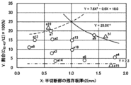
- Fig. 21 is a graph showing the relationship between the ratio ( C32-42 /t2) ⁇ 100 of the clearance C32-42 between the second die 32 and the second punch 42 to the remaining thickness t2 of the half-cut portion 21 and the remaining thickness t2 when the radius of curvature R is 1.00 mm or more.
- Fig. 22 is a graph showing the relationship between the ratio ( C32-42 /t2) ⁇ 100 of the clearance C32-42 between the second die 32 and the second punch 42 to the remaining thickness t2 of the half-cut portion 21 and the remaining thickness t2 when the radius of curvature R is less than 1.00 mm.
- 21 and 22 represent the ratio ( C32-42 /t2) x 100 (%) of the clearance C32-42 between the second die 32 and the second punch 42 to the remaining thickness t2 of the half-cut portion 21.
- the vertical axis (Y axis) represents the remaining thickness t2 of the half-cut portion 21.
- circular or triangular plots numbered "a1" and the like indicate each example.
- "a” indicates a plot of an example of the present invention
- "b” indicates a plot of a comparative example.
- the plot numbers correspond to the numbers of each example.
- the circular plots are plots showing examples in which the occurrence of ductile burrs 14 and uncut defects 15 during finish cutting could be suppressed, and the protrusion amount PA (mm) of the second shear surface 13d2 relative to the first shear surface 13d1 could be suppressed to 0.25 mm or less.
- the triangular plots are plots showing examples in which ductile burrs 14 or uncut defects 15 occurred, or the protrusion amount PA (mm) of the second shear surface 13d2 exceeded.
- the curve shown by the solid line in the graph is an approximation curve obtained from a test example in which the step 13d3 of the cut end 13 could be suppressed while increasing the remaining length L of the coating component, and corresponds to the above-mentioned formula (b3-3).
- Formula (b3-3) is shown again below.
- the regression curve or straight line denotes the ratio (C 32-42 /t2) ⁇ 100 as Y and the remaining sheet thickness t2 as X. (C 32-42 /t2) ⁇ 100 ⁇ 25.0 ⁇ t2-1...(b3-3 )
- the curve shown by the dashed line in the graph is an approximation curve obtained from a test example in which the occurrence of the uncut defect 15 was suppressed, and corresponds to the above-mentioned formula (b3-2).
- Formula (b3-2) is shown below. (C 32-42 /t2) ⁇ 100 ⁇ 7.8 ⁇ t2 2 -0.6 ⁇ t2+18.0 ... (b3-2)
- Metal processed product 2 First element 13: Cut end 13c: Sagging 13d: Sheared surface 13d1: First sheared surface 13d2: Second sheared surface 13e: Fracture surface 13f: Burr 13g: Plating layer 21: Semi-cut portion 31: First die 32: Second die 41: First punch 42: Second punch
Landscapes
- Engineering & Computer Science (AREA)
- Mechanical Engineering (AREA)
- Punching Or Piercing (AREA)
- Forging (AREA)
Priority Applications (3)
| Application Number | Priority Date | Filing Date | Title |
|---|---|---|---|
| JP2025533915A JPWO2025018081A1 (https=) | 2023-07-14 | 2024-06-18 | |
| KR1020257031395A KR20250153821A (ko) | 2023-07-14 | 2024-06-18 | 금속제 가공품의 제조 방법 및 금속제 가공품 |
| CN202480018361.0A CN120882512A (zh) | 2023-07-14 | 2024-06-18 | 金属制加工品的制造方法以及金属制加工品 |
Applications Claiming Priority (2)
| Application Number | Priority Date | Filing Date | Title |
|---|---|---|---|
| JP2023-116110 | 2023-07-14 | ||
| JP2023116110 | 2023-07-14 |
Publications (1)
| Publication Number | Publication Date |
|---|---|
| WO2025018081A1 true WO2025018081A1 (ja) | 2025-01-23 |
Family
ID=94281756
Family Applications (1)
| Application Number | Title | Priority Date | Filing Date |
|---|---|---|---|
| PCT/JP2024/022100 Pending WO2025018081A1 (ja) | 2023-07-14 | 2024-06-18 | 金属製加工品の製造方法及び金属製加工品 |
Country Status (5)
| Country | Link |
|---|---|
| JP (1) | JPWO2025018081A1 (https=) |
| KR (1) | KR20250153821A (https=) |
| CN (1) | CN120882512A (https=) |
| TW (1) | TWI909514B (https=) |
| WO (1) | WO2025018081A1 (https=) |
Citations (2)
| Publication number | Priority date | Publication date | Assignee | Title |
|---|---|---|---|---|
| JP2008155218A (ja) * | 2006-12-21 | 2008-07-10 | Nisshin Steel Co Ltd | 銅めっき鋼板の半抜き加工方法 |
| WO2022039168A1 (ja) * | 2020-08-17 | 2022-02-24 | 日本製鉄株式会社 | 加工品及び加工品製造方法 |
Family Cites Families (1)
| Publication number | Priority date | Publication date | Assignee | Title |
|---|---|---|---|---|
| MX2023001895A (es) * | 2020-08-17 | 2023-03-10 | Nippon Steel Corp | Producto procesado y metodo de produccion de producto procesado. |
-
2024
- 2024-06-18 WO PCT/JP2024/022100 patent/WO2025018081A1/ja active Pending
- 2024-06-18 KR KR1020257031395A patent/KR20250153821A/ko active Pending
- 2024-06-18 CN CN202480018361.0A patent/CN120882512A/zh active Pending
- 2024-06-18 JP JP2025533915A patent/JPWO2025018081A1/ja active Pending
- 2024-06-25 TW TW113123547A patent/TWI909514B/zh active
Patent Citations (2)
| Publication number | Priority date | Publication date | Assignee | Title |
|---|---|---|---|---|
| JP2008155218A (ja) * | 2006-12-21 | 2008-07-10 | Nisshin Steel Co Ltd | 銅めっき鋼板の半抜き加工方法 |
| WO2022039168A1 (ja) * | 2020-08-17 | 2022-02-24 | 日本製鉄株式会社 | 加工品及び加工品製造方法 |
Also Published As
| Publication number | Publication date |
|---|---|
| TWI909514B (zh) | 2025-12-21 |
| JPWO2025018081A1 (https=) | 2025-01-23 |
| KR20250153821A (ko) | 2025-10-27 |
| CN120882512A (zh) | 2025-10-31 |
| TW202502463A (zh) | 2025-01-16 |
Similar Documents
| Publication | Publication Date | Title |
|---|---|---|
| KR101996158B1 (ko) | 펀칭 가공 방법, 펀칭 가공 장치, 및 적층 철심의 제조 방법 | |
| JP7140298B2 (ja) | 加工品及び加工品製造方法 | |
| US11123785B2 (en) | Surface-treated steel sheet part having cut end surface, and cutting method therefor | |
| JP7358608B2 (ja) | 加工品製造方法 | |
| JP2002321021A (ja) | 疲労特性,端面耐食性に優れた加工製品及び加工方法 | |
| WO2025018081A1 (ja) | 金属製加工品の製造方法及び金属製加工品 | |
| JP2015157314A (ja) | Zn系めっき鋼板の打抜き方法 | |
| JP7709048B2 (ja) | 加工品及び加工品製造方法 | |
| WO2025004910A1 (ja) | 金属製加工品の製造方法及び金属製加工品 | |
| JP7155784B2 (ja) | 表面処理鋼板の切断方法 | |
| JP2008155218A (ja) | 銅めっき鋼板の半抜き加工方法 | |
| HK40128290A (zh) | 金属制加工品的制造方法以及金属制加工品 | |
| JP7436841B2 (ja) | 板材の曲げ端割れの評価方法 | |
| JP3620329B2 (ja) | 高珪素鋼板の打ち抜き加工方法 | |
| JP7135767B2 (ja) | 表面処理鋼板の切断方法 | |
| EP4414111A1 (en) | Cutting device and multi-layer material | |
| KR20260003208A (ko) | 가공 장치, 금속제 부재의 제조 방법, 및 금속제 부재 | |
| HK40082945A (en) | Processed product and method for producing processed product | |
| HK40083549A (en) | Processed article and method for manufacturing processed article | |
| WO2025134922A1 (ja) | 金属製部品の製造方法及び金属製部品 | |
| JP3057987B2 (ja) | 打抜加工性が優れたチタン合金材および打抜加工方法 | |
| CN115770811A (zh) | 一种汽车零部件冲压方法 | |
| JPH10118724A (ja) | 疲労耐久性に優れた厚手鋼板の打抜方法 |
Legal Events
| Date | Code | Title | Description |
|---|---|---|---|
| 121 | Ep: the epo has been informed by wipo that ep was designated in this application |
Ref document number: 24842877 Country of ref document: EP Kind code of ref document: A1 |
|
| ENP | Entry into the national phase |
Ref document number: 2025533915 Country of ref document: JP Kind code of ref document: A |
|
| WWE | Wipo information: entry into national phase |
Ref document number: 2025533915 Country of ref document: JP |
|
| WWE | Wipo information: entry into national phase |
Ref document number: 202480018361.0 Country of ref document: CN |
|
| ENP | Entry into the national phase |
Ref document number: 1020257031395 Country of ref document: KR Free format text: ST27 STATUS EVENT CODE: A-0-1-A10-A15-NAP-PA0105 (AS PROVIDED BY THE NATIONAL OFFICE) |
|
| WWP | Wipo information: published in national office |
Ref document number: 1020257031395 Country of ref document: KR |
|
| WWP | Wipo information: published in national office |
Ref document number: 202480018361.0 Country of ref document: CN |
|
| NENP | Non-entry into the national phase |
Ref country code: DE |