WO2025017883A1 - 信号抽出装置、および信号抽出方法 - Google Patents
信号抽出装置、および信号抽出方法 Download PDFInfo
- Publication number
- WO2025017883A1 WO2025017883A1 PCT/JP2023/026455 JP2023026455W WO2025017883A1 WO 2025017883 A1 WO2025017883 A1 WO 2025017883A1 JP 2023026455 W JP2023026455 W JP 2023026455W WO 2025017883 A1 WO2025017883 A1 WO 2025017883A1
- Authority
- WO
- WIPO (PCT)
- Prior art keywords
- signal
- sound source
- data
- target sound
- model
- Prior art date
- Legal status (The legal status is an assumption and is not a legal conclusion. Google has not performed a legal analysis and makes no representation as to the accuracy of the status listed.)
- Pending
Links
Images






Classifications
-
- G—PHYSICS
- G10—MUSICAL INSTRUMENTS; ACOUSTICS
- G10L—SPEECH ANALYSIS TECHNIQUES OR SPEECH SYNTHESIS; SPEECH RECOGNITION; SPEECH OR VOICE PROCESSING TECHNIQUES; SPEECH OR AUDIO CODING OR DECODING
- G10L21/00—Speech or voice signal processing techniques to produce another audible or non-audible signal, e.g. visual or tactile, in order to modify its quality or its intelligibility
- G10L21/02—Speech enhancement, e.g. noise reduction or echo cancellation
- G10L21/0208—Noise filtering
-
- G—PHYSICS
- G10—MUSICAL INSTRUMENTS; ACOUSTICS
- G10L—SPEECH ANALYSIS TECHNIQUES OR SPEECH SYNTHESIS; SPEECH RECOGNITION; SPEECH OR VOICE PROCESSING TECHNIQUES; SPEECH OR AUDIO CODING OR DECODING
- G10L21/00—Speech or voice signal processing techniques to produce another audible or non-audible signal, e.g. visual or tactile, in order to modify its quality or its intelligibility
- G10L21/02—Speech enhancement, e.g. noise reduction or echo cancellation
- G10L21/0272—Voice signal separating
-
- G—PHYSICS
- G10—MUSICAL INSTRUMENTS; ACOUSTICS
- G10L—SPEECH ANALYSIS TECHNIQUES OR SPEECH SYNTHESIS; SPEECH RECOGNITION; SPEECH OR VOICE PROCESSING TECHNIQUES; SPEECH OR AUDIO CODING OR DECODING
- G10L25/00—Speech or voice analysis techniques not restricted to a single one of groups G10L15/00 - G10L21/00
- G10L25/27—Speech or voice analysis techniques not restricted to a single one of groups G10L15/00 - G10L21/00 characterised by the analysis technique
- G10L25/30—Speech or voice analysis techniques not restricted to a single one of groups G10L15/00 - G10L21/00 characterised by the analysis technique using neural networks
Definitions
- the present invention relates to a signal extraction device and a signal extraction method.
- Non-Patent Document 1 a discriminative target sound source extraction system has been proposed in which an observed signal and some kind of clue that can identify the target sound, such as a pre-recorded voice of the target speaker, is input into a DNN (Deep Neural Network) model, and a target sound source signal is output (see Non-Patent Document 1).
- a DNN Deep Neural Network
- Non-Patent Document 2 It has also been disclosed that noise can be removed from observed signals using a diffusion model that generates data by inversely changing a Markov process that changes the data to be generated into Gaussian noise (see Non-Patent Document 2).
- the present invention has been made in consideration of the above, and aims to extract a target sound source signal from a mixed signal with high accuracy, which is not possible with conventional technology.
- the signal extraction device is characterized by having an acquisition unit that acquires a mixed signal of multiple sound sources and clue information of a target sound source, an estimation unit that inputs the acquired mixed signal, the clues of the target sound source, and data in a sampled step into a trained model and estimates a score corresponding to the data, and an extraction unit that uses the estimated score to extract a signal of the target sound source from the mixed signal of multiple sound sources.
- the present invention makes it possible to extract the target sound source signal from a mixed signal with high accuracy.
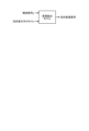
- FIG. 1 is a diagram for explaining an overview of a signal extraction device according to the present embodiment.
- FIG. 2 is a diagram for explaining an overview of the signal extraction device of this embodiment.
- FIG. 3 is a diagram for explaining an outline of the signal extraction device of this embodiment.
- FIG. 4 is a diagram for explaining an overview of the signal extraction device of this embodiment.
- FIG. 5 is a diagram for explaining an outline of the signal extraction device of this embodiment.
- FIG. 6 is a schematic diagram illustrating a schematic configuration of a signal extraction device according to the present embodiment.
- FIG. 7 is a diagram for explaining the signal extraction process.
- FIG. 8 is a diagram for explaining the signal extraction process.
- FIG. 9 is a flowchart showing the procedure of the signal extraction process.
- FIG. 10 is a diagram for explaining the embodiment.
- FIG. 11 is a diagram for explaining the embodiment.
- FIG. 12 is a diagram illustrating an example of a computer that executes a signal extraction program.
- FIG. 1 illustrates a conventional deterministic target sound source extraction process.
- an observed signal y and some clue c that can identify a target sound such as a pre-recorded target speaker's voice are input to a voice extraction model, and a target sound source signal is output.
- This voice extraction model is trained using a DNN to minimize the difference between a correct answer signal and an output signal. Since this voice extraction model is not a data generation model that follows a probability distribution, it can only generate deterministic voice that outputs the same result regardless of timing. Therefore, there is no mechanism for improving when a failure such as a signal different from the target is included.
- Fig. 2 illustrates the processing of a conventional diffusion model.
- data x0 is generated using a Markov process (reverse process) that changes data to be generated from x0 to xT in the reverse direction, in contrast to a Markov process (forward process) that changes data to be generated from x0 to Gaussian noise xT.
- the DNN is trained to realize one step p ( xT
- FIG. 3 illustrates the process of a Score Based Diffusion model that uses a value called Score in the Diffusion model shown in FIG. 2.
- the Score Based Diffusion model uses a stochastic differential equation (SDE) that describes continuous state transitions.
- the DNN Score model
- the trained Score model is used to repeat inference of one step of transition (data x t at step t) to generate data.
- FIG. 4 also illustrates a process for removing noise from a voice signal (see Non-Patent Document 2) using the Score Based Diffusion model shown in FIG. 3.
- this technology uses a DNN (Score model) similar to that shown in FIG. 3 to generate clean voice with noise removed under the conditions of the observed signal y.
- This DNN is a noise removal model and cannot extract the target sound source.
- the signal extraction device of this embodiment uses the Score Based Diffusion model (Score model) shown in Figure 3 to generate a signal of the target sound source under the conditions of the observed signal y and the clue c of the target sound source.
- Score model Score Based Diffusion model
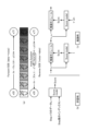
- the signal extraction process of this embodiment is illustrated in Fig. 5.
- the Score model of the signal extraction device uses a forward process shown in the following formula (1) that changes the data to be generated from x0 to Gaussian noise xT , and a reverse process shown in the following formula (2) that changes the data in the reverse direction from x0 to xT .
- data x0 is generated by repeating the inference of data xt at step t.
- the signal extraction device generates a speech signal of the target sound source using a diffusion model, which is a generative model. This makes it possible to improve the auditory quality, such as improving the performance of PESQ (Perceptual Evaluation of Speech Quality).
- the inference result changes probabilistically depending on the random number seed used when sampling the inference step number t, etc., as shown in Figs. 5(b) and (c). Therefore, the signal extraction device performs an ensemble of the inference results. This makes it possible to improve the accuracy of the inference result.
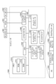
- FIG. 6 is a schematic diagram illustrating a schematic configuration of a signal extraction device of this embodiment.
- a signal extraction device 10 of this embodiment is realized by a general-purpose computer such as a personal computer, and includes an input unit 11, an output unit 12, a communication control unit 13, a storage unit 14, and a control unit 15.
- the input unit 11 is realized using input devices such as a microphone, keyboard, and mouse, and inputs various instruction information, such as starting processing, to the control unit 15 in response to input operations by an operator.
- the output unit 12 is realized by a display device such as a liquid crystal display, a printing device such as a printer, and the like. For example, the output unit 12 displays the results of the signal extraction processing described below.
- the communication control unit 13 is realized by a NIC (Network Interface Card) or the like, and controls communication between the control unit 15 and external devices via telecommunication lines such as a LAN (Local Area Network) or the Internet.
- the communication control unit 13 controls communication between the control unit 15 and a management device that manages various types of information.
- the storage unit 14 is realized by a semiconductor memory element such as a RAM (Random Access Memory) or a flash memory, or a storage device such as a hard disk or an optical disk.
- the storage unit 14 stores in advance the processing program that operates the signal extraction device 10 and data used during execution of the processing program, or stores the data temporarily each time processing is performed.
- the storage unit 14 may be configured to communicate with the control unit 15 via the communication control unit 13.
- the storage unit 14 stores the model 14a or the cascade model 140a, etc., used in the signal extraction process described below.
- the control unit 15 is realized using a CPU (Central Processing Unit), NP (Network Processor), FPGA (Field Programmable Gate Array), etc., and executes processing programs stored in memory. As a result, the control unit 15 functions as an acquisition unit 15a, a learning unit 15b, an estimation unit 15c, and an extraction unit 15d, as exemplified in FIG. 6, to execute signal extraction processing. Note that each of these functional units, or some of them, may be implemented in different hardware. The control unit 15 may also have other functional units.
- CPU Central Processing Unit
- NP Network Processor
- FPGA Field Programmable Gate Array
- the acquisition unit 15a acquires a mixed signal of multiple sound sources and clue information of the target sound source.
- the acquisition unit 15a acquires an observation signal y, which is a mixed signal of multiple sound sources, and some kind of clue c that can identify the target sound source, such as a pre-recorded voice of a target speaker, from a microphone or a management device that manages various information, via the input unit 11 or the communication control unit 13.
- the acquisition unit 15a may store the acquired observation signal y and clue information c of the target sound source in the storage unit 14.
- the learning unit 15b receives the acquired mixed signal y, the clue c of the target sound source, and the sampled data xt in the t-th step, and generates, by learning, a model 14a that estimates a score corresponding to the data xt. Specifically, as illustrated in Fig. 5B, when the data xt in step t , the observed signal y, and the clue c are input, a model (Score model) 14a that outputs a score corresponding to xt is generated by learning.
- This model 14a is a diffusion model that generates data x0 by a reverse process that changes the Gaussian noise xT to the target data x0 for each step.
- the model 14a is a score-based diffusion model that generates data x0 by repeating inference of data xt at step t using a score, as illustrated in FIG.
- the estimation unit 15c inputs the acquired mixed signal y, the clue c of the target sound source, and the sampled data xt at the t-th step to the trained model 14a, and estimates a score corresponding to the data. Specifically, as illustrated in FIG. 5C, the mixed signal y, the clue c of the target sound source, and xt are input to the model 14a to obtain an output of the score.
- the extraction unit 15d extracts a signal of a target sound source from the mixed signal y of the multiple sound sources by using the estimated score. Specifically, as illustrated in FIG. 5C, the extraction unit 15d repeats the process of estimating xT - ⁇ t by using the score output by the estimation unit 15c until the inference result x0 is obtained as the final output, thereby extracting the signal x0 of the target sound source.
- the extraction unit 15d may take the average value of the target sound source signal extracted in each process a predetermined number of times as the extraction result. In other words, the extraction unit 15d may change the random number seed and repeat the inference a predetermined number of times, performing an ensemble to find the average value of the inference results. This makes it possible to improve the accuracy of the inference.
- Figs. 7 and 8 are diagrams for explaining the signal extraction process.
- Fig. 7 illustrates the processing of model 14a (DNN, Score model) shown in Fig. 5.
- the learning unit 15b first creates data (y, x0 , c) using the mixed sound y as an observed signal, the target speaker sound x0 , and a randomly selected target speaker sound c as a clue to the target sound source.
- the learning unit 15b samples step number t from a uniform distribution of 0 ⁇ t ⁇ T, and samples xt using x0 according to the following equations (3) to (5).
- the learning unit 15b inputs data (y, xt , c) to the model 14a in Fig. 7 to obtain an output score.
- the learning unit 15b also calculates a loss function so as to minimize the difference between the correct score and the output score, and performs a backward calculation.
- the extraction unit 15d may perform an ensemble in which the random number seed is changed, the inference is repeated a predetermined number of times, and the average value of the inference results is calculated. This makes it possible to improve the accuracy of the inference.
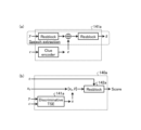
- FIG. 8(a) illustrates the processing of the model (Discriminative TSE (Target Source Extraction)) 141a of the deterministic target sound source extraction processing illustrated in FIG. 1.
- FIG. 8(b) illustrates the processing of a model (cascade model) 140a that combines the model 141a of the deterministic target sound source extraction processing in FIG. 8(a) and the model 14a of the signal extraction processing illustrated in FIG. 7.
- the learning unit 15b performs multitask learning using two loss functions: a loss function of the score and a loss function of the target speaker's voice x.
- the cascade model 140a can be used in two ways: as a diffusion model that performs inference using the score, and as a deterministic model that uses a direct estimate of x.
- the training unit 15b when training the cascade model 140a, the training unit 15b creates data (y, x0, c) using the mixed sound y as the observed signal, the target speaker sound x0 , and the target speaker sound c randomly selected as a clue to the target sound source, in the same manner as when training the model 14a in FIG. 7.
- the learning unit 15b samples step number t from a uniform distribution of 0 ⁇ t ⁇ T, and samples xt using x0 according to the above equations (1) to (3).
- the learning unit 15b inputs data (y, c) to the model 141a of the model 140a in Fig. 8B to obtain an output of x ⁇ .
- the learning unit 15b also inputs data ( xt , x ⁇ ) to the model 142a to obtain an output of a score.
- the learning unit 15b then performs calculations to minimize the loss function of the difference between the correct score and the output score, and the loss function of the difference between x ⁇ and x0 , and learns by performing backward calculations.
- the estimation unit 15c samples xT according to the above formulas (3) to (5), similarly to the inference of the model 14a in FIG. 7.
- the estimation unit 15c inputs data (y, xt , c) to the cascade model 140a to obtain a score output.
- the extraction unit 15d repeats the process of estimating xT - ⁇ t using the output score until it obtains the inference result x0 as the final output.
- the extraction unit 15d may perform an ensemble in which the seed of the random numbers is changed and inference is repeated a predetermined number of times to find the average value of the inference results. This makes it possible to improve the accuracy of the inference.
- Fig. 9 is a flowchart showing the procedure of the signal extraction process.
- the flowchart in Fig. 9 is started, for example, when a user performs an operation input to instruct the start of the process.
- the acquisition unit 15a acquires an observed signal y, which is a mixed signal of multiple sound sources, and a clue c for the target sound source (step S1).
- the estimation unit 15c inputs the acquired observed signal y, the clue c of the target sound source, and the sampled data xt at the t-th step to the trained model 14a, and estimates a score corresponding to the data (step S2). Specifically, the mixed signal y, the clue c of the target sound source, and xt are input to the trained model 14a to obtain an output of the score.
- the extraction unit 15d extracts a signal of the target sound source from the mixed signal y of the multiple sound sources using the estimated score (step S3). Specifically, the extraction unit 15d extracts the signal x 0 of the target sound source by repeating the process of estimating x T- ⁇ t using the score output by the estimation unit 15c until the inference result x 0 is obtained as the final output. This completes a series of signal extraction processes.
- the acquisition unit 15a acquires a mixed signal of multiple sound sources and clue information of a target sound source.
- the estimation unit 15c inputs the acquired mixed signal, the clue information of the target sound source, and sampled data at the t-th step to the trained model 14a and estimates a score corresponding to the data.
- the extraction unit 15d extracts a signal of the target sound source from the mixed signal of multiple sound sources using the estimated score.
- the trained model 14a is a diffusion model that generates the data by a reverse process that changes the data to be generated step by step from Gaussian noise.
- the extraction unit 15d also sets the average value of the target sound source signal extracted in each process performed a predetermined number of times as the extraction result. In this way, by using the fact that the inference result changes probabilistically when the random number seed is changed, it is possible to improve the accuracy of the inference.
- FIG. 10 and 11 are diagrams for explaining examples.
- the model 14a of the above embodiment was used, and the random number seed was changed and the inference process was repeated 10 times.
- FIG. 10 illustrates each inference result and an ensemble result obtained by simply averaging the inference results in the time-frequency domain.
- SDR Source to Distortion Ratio
- x the ensemble result
- SDR Source to Distortion Ratio
- Figure 11 illustrates the Perceptual Evaluation of Speech Quality (PESQ) as an evaluation result of each of the above methods.
- PESQ Perceptual Evaluation of Speech Quality
- a program in which the processing executed by the signal extraction device 10 according to the above embodiment is written in a language executable by a computer can also be created.
- the signal extraction device 10 can be implemented by installing a signal extraction program that executes the above signal extraction processing as package software or online software on a desired computer.
- the above signal extraction program can be executed by an information processing device, so that the information processing device can function as the signal extraction device 10.
- the information processing device here includes desktop or notebook personal computers.
- the information processing device also includes mobile communication terminals such as smartphones, mobile phones, and PHS (Personal Handyphone System), and even slate terminals such as PDA (Personal Digital Assistant).
- the function of the signal extraction device 10 may also be implemented on a cloud server.
- FIG. 12 is a diagram showing an example of a computer that executes a signal extraction program.
- the computer 1000 has, for example, a memory 1010, a CPU 1020, a hard disk drive interface 1030, a disk drive interface 1040, a serial port interface 1050, a video adapter 1060, and a network interface 1070. These components are connected by a bus 1080.
- the memory 1010 includes a ROM (Read Only Memory) 1011 and a RAM 1012.
- the ROM 1011 stores a boot program such as a BIOS (Basic Input Output System).
- BIOS Basic Input Output System
- the hard disk drive interface 1030 is connected to a hard disk drive 1031.
- the disk drive interface 1040 is connected to a disk drive 1041.
- a removable storage medium such as a magnetic disk or optical disk is inserted into the disk drive 1041.
- the serial port interface 1050 is connected to a mouse 1051 and a keyboard 1052, for example.
- the video adapter 1060 is connected to a display 1061, for example.
- the hard disk drive 1031 stores, for example, an OS (Operating System) 1091, application programs 1092, program modules 1093, and program data 1094. Each piece of information described in the above embodiment is stored, for example, in the hard disk drive 1031 or memory 1010.
- OS Operating System
- the signal extraction program is stored in the hard disk drive 1031, for example, as a program module 1093 in which instructions to be executed by the computer 1000 are written. Specifically, the program module 1093 in which each process executed by the signal extraction device 10 described in the above embodiment is written is stored in the hard disk drive 1031.
- data used for information processing by the signal extraction program is stored as program data 1094, for example, in the hard disk drive 1031.
- the CPU 1020 reads the program module 1093 and program data 1094 stored in the hard disk drive 1031 into the RAM 1012 as necessary, and executes each of the procedures described above.
- the program module 1093 and program data 1094 related to the signal extraction program are not limited to being stored in the hard disk drive 1031, but may be stored in a removable storage medium, for example, and read by the CPU 1020 via the disk drive 1041 or the like.
- the program module 1093 and program data 1094 related to the signal extraction program may be stored in another computer connected via a network, such as a LAN or WAN (Wide Area Network), and read by the CPU 1020 via the network interface 1070.
Landscapes
- Engineering & Computer Science (AREA)
- Human Computer Interaction (AREA)
- Signal Processing (AREA)
- Health & Medical Sciences (AREA)
- Audiology, Speech & Language Pathology (AREA)
- Computational Linguistics (AREA)
- Physics & Mathematics (AREA)
- Acoustics & Sound (AREA)
- Multimedia (AREA)
- Quality & Reliability (AREA)
- Artificial Intelligence (AREA)
- Evolutionary Computation (AREA)
- Circuit For Audible Band Transducer (AREA)
- Measurement Of Mechanical Vibrations Or Ultrasonic Waves (AREA)
Abstract
信号抽出装置(10)において、取得部(15a)が、複数音源の混合信号と、目的音源の手がかり情報とを取得する。推定部(15c)が、取得された混合信号と目的音源の手がかり情報と、サンプリングされたステップにおけるデータとを学習済みモデル(14a)に入力し、該データに対応するスコアを推定する。抽出部(15d)が、推定されたスコアを用いて、複数音源の混合信号から目的音源の信号を抽出する。
Description
本発明は、信号抽出装置、および信号抽出方法に関する。
近年、音声認識・話者認識での高性能化や会話アプリ等で音声を聞き取りやすくするため等に、混合音声信号から特定の話者の音声を抽出する技術が検討されている。例えば、観測信号と、事前に録音した対象話者の声等の目的音を特定できる何らかの手掛かりとを、DNN(Deep Neural Network)モデルに入力し、目的音源信号を出力する決定論的(Discriminative)な目的音源抽出システムが提案されている(非特許文献1参照)。
また、生成対象のデータからガウシアンノイズまで変化させるマルコフ過程を逆方向に変化させることにより、データを生成するDiffusion modelを用いて、観測信号から雑音除去を行うが開示されている(非特許文献2参照)。
Katerina Zmolikova, "SpeakerBeam: Speaker Aware Neural Network for Target Speaker Extraction in Speech Mixtures", IEEE JOURNAL OF SELECTED TOPICS IN SIGNAL PROCESSING, VOL. 13, NO. 4, 2019年8月
Julius Richter, "Speech Enhancement and Dereverberation with Diffusion-based Generative Models", IEEE/ACM Transactions on Audio, Speech and Language Processing, 2023年
しかしながら、従来技術では、混合信号から目的音源信号を精度高く抽出することが困難であった。例えば、抽出された目的音源信号の聴感上の品質が不十分であった。また、目的音源信号に対象信号と異なる信号の抽出等の失敗が含まれていた場合でも改善が難しかった。
本発明は、上記に鑑みてなされたものであって、従来技術では、混合信号から目的音源信号を精度高く抽出することを目的とする。
上述した課題を解決し、目的を達成するために、本発明に係る信号抽出装置は、複数音源の混合信号と、目的音源の手がかり情報とを取得する取得部と、取得された前記混合信号と前記目的音源の手がかりと、サンプリングされたステップにおけるデータとを学習済みモデルに入力し、該データに対応するスコアを推定する推定部と、推定された前記スコアを用いて、前記複数音源の混合信号から前記目的音源の信号を抽出する抽出部と、を有することを特徴とする。
本発明によれば、混合信号から目的音源信号を精度高く抽出することが可能となる。
以下、図面を参照して、本発明の一実施形態を詳細に説明する。なお、この実施形態により本発明が限定されるものではない。また、図面の記載において、同一部分には同一の符号を付して示している。
[信号抽出装置の概要]
図1~図5は、本実施形態の信号抽出装置の概要を説明するための図である。まず、図1には、従来の決定論的な目的音源抽出の処理が例示されている。図1に示すように、決定論的な目的音源抽出では、観測信号yと、事前に録音した目的話者の音声等の目的音声を特定できる何らかの手がかりcを、音声抽出モデルに入力し、目的音源信号が出力される。この音声抽出モデルは、DNNを用いて、正解信号と出力信号との差を最小にするように学習される。この音声抽出モデルは確率分布に従うデータ生成モデルではないため、タイミングに関わらず同じ結果を出力する決定論的な音声の生成しかできない。そのため、目的と異なる信号等の失敗が含まれていた場合に改善する仕組みがない。
図1~図5は、本実施形態の信号抽出装置の概要を説明するための図である。まず、図1には、従来の決定論的な目的音源抽出の処理が例示されている。図1に示すように、決定論的な目的音源抽出では、観測信号yと、事前に録音した目的話者の音声等の目的音声を特定できる何らかの手がかりcを、音声抽出モデルに入力し、目的音源信号が出力される。この音声抽出モデルは、DNNを用いて、正解信号と出力信号との差を最小にするように学習される。この音声抽出モデルは確率分布に従うデータ生成モデルではないため、タイミングに関わらず同じ結果を出力する決定論的な音声の生成しかできない。そのため、目的と異なる信号等の失敗が含まれていた場合に改善する仕組みがない。
一方、図2には、従来のDiffusion modelの処理が例示されている。図2に示すように、Diffusion modelでは生成対象のデータx0からガウシアンノイズxTまで変化させるマルコフ過程(forward process)に対し、x0からxTへ逆方向に変化させるマルコフ過程(Reverse process)を用いて、データx0を生成する。この場合のDNNは、Reverse processの1ステップp(xT|xT-1)を実現するように学習が行われる。
また、図3には、図2に示したDiffusion modelに、Scoreと呼ばれる値を用いるScore Based Diffusion modelの処理が例示されている。具体的には、図3(a)に示すように、Score Based Diffusion modelでは、連続的な状態遷移を記述する確率微分方程式(SDE、Stochastic Differential Equations)が用いられる。この場合のDNN(Score model)は、図3(b)に例示するように、生成するデータに対応する正解Scoreの値を教師データとして用いて学習される。そして、図3(c)に例示するように、学習されたScore modelを用いて、1ステップの推移(ステップtでのデータxt)の推論を繰り返すことにより、データが生成される。
また、図4には、図3に示したScore Based Diffusion modelを用いて、音声信号の雑音除去を行う処理(非特許文献2参照)が例示されている。図4(a)(b)に示すように、この技術では、図3と同様のDNN(Score model)を用いて、観測信号yの条件の下に、雑音除去されたクリーン音声が生成される。このDNNは、雑音除去モデルであり、目的音源の抽出はできない。また、失敗が含まれていた場合にも改善する仕組みがない。
そこで、本実施形態の信号抽出装置は、図3に示したScore Based Diffusion model(Score model)を用いて、観測信号yおよび目的音源の手がかりcの条件の下に、目的音源の信号を生成する。
ここで、図5には、本実施形態の信号抽出処理が例示されている。具体的には、信号抽出装置のScore modelは、図5(a)に示すように、生成対象のデータx0からガウシアンノイズxTまで変化させる次式(1)に示すforward processに対し、x0からxTへ逆方向に変化させる次式(2)に示すReverse processを用いる。そして、ステップtでのデータxtの推論を繰り返すことにより、データx0を生成する。


このように、信号抽出装置は、生成モデルであるDiffusion modelを用いて目的音源の音声信号を生成する。これにより、PESQ(Perceptual Evaluation of Speech Quality)の性能向上等、聴覚上の品質向上が可能となる。
また、信号抽出装置では、図5(b)(c)に例示する、推論のステップ番号t等のサンプリングの際の乱数のシードによって確率的に推論結果が変わる。そこで、信号抽出装置は、推論結果のアンサンブルを行う。これにより、推論結果の精度向上が可能となる。
[信号抽出装置の構成]
図6は、本実施形態の信号抽出装置の概略構成を例示する模式図である。図6に例示するように、本実施形態の信号抽出装置10は、パソコン等の汎用コンピュータで実現され、入力部11、出力部12、通信制御部13、記憶部14、および制御部15を備える。
図6は、本実施形態の信号抽出装置の概略構成を例示する模式図である。図6に例示するように、本実施形態の信号抽出装置10は、パソコン等の汎用コンピュータで実現され、入力部11、出力部12、通信制御部13、記憶部14、および制御部15を備える。
入力部11は、マイクやキーボードやマウス等の入力デバイスを用いて実現され、操作者による入力操作に対応して、制御部15に対して処理開始などの各種指示情報を入力する。出力部12は、液晶ディスプレイなどの表示装置、プリンター等の印刷装置等によって実現される。例えば、出力部12には、後述する信号抽出処理の結果が表示される。
通信制御部13は、NIC(Network Interface Card)等で実現され、LAN(Local Area Network)やインターネットなどの電気通信回線を介した外部の装置と制御部15との通信を制御する。例えば、通信制御部13は、各種情報を管理する管理装置等と制御部15との通信を制御する。
記憶部14は、RAM(Random Access Memory)、フラッシュメモリ(Flash Memory)等の半導体メモリ素子、または、ハードディスク、光ディスク等の記憶装置によって実現される。記憶部14には、信号抽出装置10を動作させる処理プログラムや、処理プログラムの実行中に使用されるデータなどが予め記憶され、あるいは処理の都度一時的に記憶される。なお、記憶部14は、通信制御部13を介して制御部15と通信する構成でもよい。
本実施形態において、記憶部14は、後述する信号抽出処理で使用されるモデル14aまたはカスケードモデル140a等を記憶する。
制御部15は、CPU(Central Processing Unit)やNP(Network Processor)やFPGA(Field Programmable Gate Array)等を用いて実現され、メモリに記憶された処理プログラムを実行する。これにより、制御部15は、図6に例示するように、取得部15a、学習部15b、推定部15c、および抽出部15dとして機能して、信号抽出処理を実行する。なお、これらの機能部は、それぞれ、あるいは一部が異なるハードウェアに実装されてもよい。また、制御部15は、その他の機能部を備えてもよい。
取得部15aは、複数音源の混合信号と、目的音源の手がかり情報とを取得する。例えば、取得部15aは、入力部11あるいは通信制御部13を介して、マイクや各種情報を管理する管理装置等から、複数音源の混合信号である観測信号yと、事前に録音した目的話者の音声等の目的音源を特定できる何らかの手がかりcとを取得する。取得部15aは、取得した観測信号yと、目的音源の手がかり情報cとを記憶部14に記憶させてもよい。
学習部15bは、取得された混合信号yと目的音源の手がかりcと、サンプリングされたt番目のステップにおけるデータxtとを入力すると、該データxtに対応するスコアを推定するモデル14aを学習により生成する。具体的には、図5(b)に例示したように、ステップtでのデータxtと観測信号yと手がかりcとを入力すると、xtに対応するスコアを出力するモデル(Score model)14aを学習により生成する。
このモデル14aは、ガウシアンノイズxTから生成対象のデータx0にステップごとに変化させる逆過程(Reverse Process)により該データx0を生成するDiffusion modelである。具体的には、モデル14aは、図5(a)に例示したように、スコアを用いたステップtでのデータxtの推論を繰り返すことにより、データx0を生成するScore Baced diffusion modelである。
推定部15cは、取得された混合信号yと目的音源の手がかりcと、サンプリングされたt番目のステップにおけるデータxtとを学習済みのモデル14aに入力し、該データに対応するスコアを推定する。具体的には、図5(c)に例示したように、モデル14aに混合信号yと目的音源の手がかりcとxtとを入力してスコアの出力を得る。
抽出部15dは、推定されたスコアを用いて、複数音源の混合信号yから目的音源の信号を抽出する。具体的には、抽出部15dは、図5(c)に例示したように、推定部15cにより出力されたスコアを用いて、xT-Δtを推定する処理を、最終的な出力として推論結果x0を得るまで繰り返すことにより、目的音源の信号x0を抽出する。
ここで、サンプリングの際の乱数のシードを変えると、推論結果は確率的に変わる。そこで、抽出部15dは、所定回数の各処理において抽出された目的音源の信号の平均値を抽出結果としてもよい。つまり、抽出部15dは、乱数のseedを変えて所定回数の推論を繰り返し、推論結果の平均値を求めるアンサンブルを行ってもよい。これにより、推論の精度を向上させることが可能となる。
ここで、図7および図8は、信号抽出処理を説明するための図である。まず、図7には、図5に示したモデル14a(DNN、Score model)の処理が例示されている。
具体的には、学習時(図5(b)参照)には、学習部15bは、まず、観測信号として混合音声y、目的話者音声x0、目的音源の手がかりとしてランダムに選んだ目的話者の音声cを用いて、データ(y,x0,c)を作成する。
また、学習部15bは、0≦t≦Tの一様分布からステップ番号tのサンプリングを行うとともに、次式(3)~(5)に従い、x0を用いてxtのサンプリングを行う。



そして、学習部15bは、図7のモデル14aにデータ(y,xt,c)を入力してスコア(score)の出力を得る。また、学習部15bは、正解スコアと出力スコアとの差を最小化するようにloss関数を計算し、backward計算を行う。
また、推論時(図5(c)参照)には、推定部15cが、上記式(3)~(5)に従い、xTのサンプリングを行う。また、[0,T]をN分割してΔt=T/Nとし、(xT,xT-Δt、…,x0)において、reverse processによる不連続な状態遷移を行う。具体的には、推定部15cは、モデル14aにデータ(y,xt,c)を入力してスコアの出力を得る。また、抽出部15dは、出力されたスコアを用いて、xT-Δtを推定する処理を、最終的な出力として推論結果x0を得るまで繰り返す。
なお、サンプリングの際の乱数のシードを変えると、推論結果は確率的に変わる。そこで、抽出部15dは、乱数のseedを変えて所定回数の推論を繰り返し、推論結果の平均値を求めるアンサンブルを行ってもよい。これにより、推論の精度を向上させることが可能となる。
また、図8(a)には、図1に例示した決定論的な目的音源抽出処理のモデル(Discriminative TSE(Target Source Extraction))141aの処理が例示されている。また、図8(b)には、図8(a)の決定論的な目的音源抽出処理のモデル141aと、図7に示した信号抽出処理のモデル14aとを組み合わせたモデル(カスケードモデル)140aの処理が例示されている。
カスケードモデル140aでは、学習部15bは、スコアのloss関数と目的話者音声xのloss関数との2つのloss関数を用いてマルチタスク学習を行う。また、カスケードモデル140aは、スコアを用いた推論を行うDiffusion modelとして、またxの直接推定値を用いる決定論的なモデルとして、2つの使い方が可能である。
具体的には、カスケードモデル140aの学習時には、学習部15bは、図7のモデル14aの学習時と同様に、観測信号として混合音声y、目的話者音声x0、目的音源の手がかりとしてランダムに選んだ目的話者の音声cを用いて、データ(y,x0,c)を作成する。
また、学習部15bは、0≦t≦Tの一様分布からステップ番号tのサンプリングを行うとともに、上記式(1)~(3)に従い、x0を用いてxtのサンプリングを行う。
そして、学習部15bは、図8(b)のモデル140aのうち、モデル141aにデータ(y,c)を入力してx^の出力を得る。また、学習部15bは、モデル142aにデータ(xt,x^)を入力してスコア(score)の出力を得る。そして、学習部15bは、正解スコアと出力スコアとの差のloss関数と、x^とx0との差のloss関数とをそれぞれ最小化するように計算し、backward計算を行うことにより学習する。
カスケードモデル140aの推論時には、推定部15cが、図7のモデル14aの推論時と同様に、上記式(3)~(5)に従い、xTのサンプリングを行う。また、推定部15cは、[0,T]をN分割してΔt=T/Nとし、(xT,xT-Δt、…,x0)において、reverse processによる不連続な状態遷移を行う。具体的には、推定部15cは、カスケードモデル140aにデータ(y,xt,c)を入力してスコアの出力を得る。また、抽出部15dが、出力されたスコアを用いて、xT-Δtを推定する処理を、最終的な出力として推論結果x0を得るまで繰り返す。
なお、図7に示した例と同様に、サンプリングの際の乱数のseedを変えると、推論結果は確率的に変わる。そこで、抽出部15dは、乱数のseedを変えて所定回数の推論を繰り返し、推論結果の平均値を求めるアンサンブルを行ってもよい。これにより、推論の精度を向上させることが可能となる。
[信号抽出処理]
次に、図9を参照して、本実施形態に係る信号抽出装置10による信号抽出処理について説明する。図9は、信号抽出処理手順を示すフローチャートである。図9のフローチャートは、例えば、ユーザが開始を指示する操作入力を行ったタイミングで開始される。
次に、図9を参照して、本実施形態に係る信号抽出装置10による信号抽出処理について説明する。図9は、信号抽出処理手順を示すフローチャートである。図9のフローチャートは、例えば、ユーザが開始を指示する操作入力を行ったタイミングで開始される。
まず、取得部15aが、複数音源の混合信号である観測信号yと、目的音源の手がかりcとを取得する(ステップS1)。
次に、推定部15cが、取得された観測信号yと目的音源の手がかりcと、サンプリングされたt番目のステップにおけるデータxtとを学習済みのモデル14aに入力し、該データに対応するスコアを推定する(ステップS2)。具体的には、学習済のモデル14aに混合信号yと目的音源の手がかりcとxtとを入力してスコアの出力を得る。
そして、抽出部15dが、推定されたスコアを用いて、複数音源の混合信号yから目的音源の信号を抽出する(ステップS3)。具体的には、抽出部15dは、推定部15cにより出力されたスコアを用いて、xT-Δtを推定する処理を、最終的な出力として推論結果x0を得るまで繰り返すことにより、目的音源の信号x0を抽出する。これにより、一連の信号抽出処理が終了する。
[効果]
以上、説明したように、本実施形態の信号抽出装置10において、取得部15aが、複数音源の混合信号と、目的音源の手がかり情報とを取得する。推定部15cが、取得された混合信号と目的音源の手がかり情報と、サンプリングされたt番目のステップにおけるデータとを学習済みモデル14aに入力し、該データに対応するスコアを推定する。抽出部15dが、推定されたスコアを用いて、複数音源の混合信号から目的音源の信号を抽出する。
以上、説明したように、本実施形態の信号抽出装置10において、取得部15aが、複数音源の混合信号と、目的音源の手がかり情報とを取得する。推定部15cが、取得された混合信号と目的音源の手がかり情報と、サンプリングされたt番目のステップにおけるデータとを学習済みモデル14aに入力し、該データに対応するスコアを推定する。抽出部15dが、推定されたスコアを用いて、複数音源の混合信号から目的音源の信号を抽出する。
具体的には、学習済みモデル14aは、ガウシアンノイズから生成対象のデータにステップごとに変化させる逆過程により該データを生成するDiffusion modelである。
このように、確率分布に基づく生成モデルを用いることにより、PESQの性能向上等、聴感上の品櫃向上が可能となる。したがって、混合信号から目的音源信号を精度高く抽出することが可能となる。
また、抽出部15dは、所定回数の各処理において抽出された目的音源の信号の平均値を抽出結果とする。このように、乱数のseedを変えると推論結果が確率的に変わることを用いて、推論の精度を向上させることが可能となる。
[実施例]
図10および図11は、実施例を説明するための図である。まず、図10に示す実施例では、上記実施形態のモデル14aを用いて、乱数のシードを変えて10回推論処理を繰り返した。図10には、各推論結果と、推論結果を時間周波数領域で単純平均したアンサンブル結果とが例示されている。図10(a)に例示するように、「・」で示す各推論結果(Extracted samples)のSDR(Source to Distortion Ratio)より、「×」で示すアンサンブル結果(Ensemble)のSDRの方が良いことが確認された。
図10および図11は、実施例を説明するための図である。まず、図10に示す実施例では、上記実施形態のモデル14aを用いて、乱数のシードを変えて10回推論処理を繰り返した。図10には、各推論結果と、推論結果を時間周波数領域で単純平均したアンサンブル結果とが例示されている。図10(a)に例示するように、「・」で示す各推論結果(Extracted samples)のSDR(Source to Distortion Ratio)より、「×」で示すアンサンブル結果(Ensemble)のSDRの方が良いことが確認された。
なお、図10(b)には、アンサンブルの一例が示されている。図に太枠で囲んだ部分でわかるように、混合信号(Mixture)に対する目的音源(target)の推論結果を、アンサンブル結果(Ensemble)がよりよく表すことが確認された。
また、図11には、上記の各手法の評価結果として、音声品質の知覚評価指標(PESQ、Perceptual Evaluation of Speech Quality)が例示されている。図11に示すように、図7に例示した本発明のモデル14aでは、アンサンブルにより、図1、図8(a)に例示した従来法のDiscriminativeTSEより性能が高いことが確認された。また、図8(b)に例示した本発明のカスケードモデル140aでは、アンサンブルの有無にかかわらず、従来法のDiscriminativeTSEより性能が高いことが確認された。
[プログラム]
上記実施形態に係る信号抽出装置10が実行する処理をコンピュータが実行可能な言語で記述したプログラムを作成することもできる。一実施形態として、信号抽出装置10は、パッケージソフトウェアやオンラインソフトウェアとして上記の信号抽出処理を実行する信号抽出プログラムを所望のコンピュータにインストールさせることによって実装できる。例えば、上記の信号抽出プログラムを情報処理装置に実行させることにより、情報処理装置を信号抽出装置10として機能させることができる。ここで言う情報処理装置には、デスクトップ型またはノート型のパーソナルコンピュータが含まれる。また、その他にも、情報処理装置にはスマートフォン、携帯電話機やPHS(Personal Handyphone System)などの移動体通信端末、さらには、PDA(Personal Digital Assistant)などのスレート端末などがその範疇に含まれる。また、信号抽出装置10の機能を、クラウドサーバに実装してもよい。
上記実施形態に係る信号抽出装置10が実行する処理をコンピュータが実行可能な言語で記述したプログラムを作成することもできる。一実施形態として、信号抽出装置10は、パッケージソフトウェアやオンラインソフトウェアとして上記の信号抽出処理を実行する信号抽出プログラムを所望のコンピュータにインストールさせることによって実装できる。例えば、上記の信号抽出プログラムを情報処理装置に実行させることにより、情報処理装置を信号抽出装置10として機能させることができる。ここで言う情報処理装置には、デスクトップ型またはノート型のパーソナルコンピュータが含まれる。また、その他にも、情報処理装置にはスマートフォン、携帯電話機やPHS(Personal Handyphone System)などの移動体通信端末、さらには、PDA(Personal Digital Assistant)などのスレート端末などがその範疇に含まれる。また、信号抽出装置10の機能を、クラウドサーバに実装してもよい。
図12は、信号抽出プログラムを実行するコンピュータの一例を示す図である。コンピュータ1000は、例えば、メモリ1010と、CPU1020と、ハードディスクドライブインタフェース1030と、ディスクドライブインタフェース1040と、シリアルポートインタフェース1050と、ビデオアダプタ1060と、ネットワークインタフェース1070とを有する。これらの各部は、バス1080によって接続される。
メモリ1010は、ROM(Read Only Memory)1011およびRAM1012を含む。ROM1011は、例えば、BIOS(Basic Input Output System)等のブートプログラムを記憶する。ハードディスクドライブインタフェース1030は、ハードディスクドライブ1031に接続される。ディスクドライブインタフェース1040は、ディスクドライブ1041に接続される。ディスクドライブ1041には、例えば、磁気ディスクや光ディスク等の着脱可能な記憶媒体が挿入される。シリアルポートインタフェース1050には、例えば、マウス1051およびキーボード1052が接続される。ビデオアダプタ1060には、例えば、ディスプレイ1061が接続される。
ここで、ハードディスクドライブ1031は、例えば、OS(Operating System)1091、アプリケーションプログラム1092、プログラムモジュール1093およびプログラムデータ1094を記憶する。上記実施形態で説明した各情報は、例えばハードディスクドライブ1031やメモリ1010に記憶される。
また、信号抽出プログラムは、例えば、コンピュータ1000によって実行される指令が記述されたプログラムモジュール1093として、ハードディスクドライブ1031に記憶される。具体的には、上記実施形態で説明した信号抽出装置10が実行する各処理が記述されたプログラムモジュール1093が、ハードディスクドライブ1031に記憶される。
また、信号抽出プログラムによる情報処理に用いられるデータは、プログラムデータ1094として、例えば、ハードディスクドライブ1031に記憶される。そして、CPU1020が、ハードディスクドライブ1031に記憶されたプログラムモジュール1093やプログラムデータ1094を必要に応じてRAM1012に読み出して、上述した各手順を実行する。
なお、信号抽出プログラムに係るプログラムモジュール1093やプログラムデータ1094は、ハードディスクドライブ1031に記憶される場合に限られず、例えば、着脱可能な記憶媒体に記憶されて、ディスクドライブ1041等を介してCPU1020によって読み出されてもよい。あるいは、信号抽出プログラムに係るプログラムモジュール1093やプログラムデータ1094は、LANやWAN(Wide Area Network)等のネットワークを介して接続された他のコンピュータに記憶され、ネットワークインタフェース1070を介してCPU1020によって読み出されてもよい。
以上、本発明者によってなされた発明を適用した実施形態について説明したが、本実施形態による本発明の開示の一部をなす記述および図面により本発明は限定されることはない。すなわち、本実施形態に基づいて当業者等によりなされる他の実施形態、実施例および運用技術等は全て本発明の範疇に含まれる。
10 信号抽出装置
11 入力部
12 出力部
13 通信制御部
14 記憶部
14a、140a、141a、142a モデル
15 制御部
15a 取得部
15b 学習部
15c 推定部
15d 抽出部
11 入力部
12 出力部
13 通信制御部
14 記憶部
14a、140a、141a、142a モデル
15 制御部
15a 取得部
15b 学習部
15c 推定部
15d 抽出部
Claims (4)
- 複数音源の混合信号と、目的音源の手がかり情報とを取得する取得部と、
取得された前記混合信号と前記目的音源の手がかり情報と、サンプリングされたステップにおけるデータとを学習済みモデルに入力し、該データに対応するスコアを推定する推定部と、
推定された前記スコアを用いて、前記複数音源の混合信号から前記目的音源の信号を抽出する抽出部と、
を有することを特徴とする信号抽出装置。 - 前記学習済みモデルは、ガウシアンノイズから生成対象のデータにステップごとに変化させる逆過程により該データを生成するDiffusion modelであることを特徴とする請求項1に記載の信号抽出装置。
- 前記抽出部は、所定回数の各処理において抽出された前記目的音源の信号の平均値を抽出結果とすることを特徴とする請求項1に記載の信号抽出装置。
- 信号抽出装置が実行する信号抽出方法であって、
複数音源の混合信号と、目的音源の手がかり情報とを取得する取得工程と、
取得された前記混合信号と前記目的音源の手がかり情報と、サンプリングされたステップにおけるデータとを学習済みモデルに入力し、該データに対応するスコアを推定する推定工程と、
推定された前記スコアを用いて、前記複数音源の混合信号から前記目的音源の信号を抽出する抽出工程と、
を含んだことを特徴とする信号抽出方法。
Priority Applications (3)
| Application Number | Priority Date | Filing Date | Title |
|---|---|---|---|
| PCT/JP2023/026455 WO2025017883A1 (ja) | 2023-07-19 | 2023-07-19 | 信号抽出装置、および信号抽出方法 |
| JP2025533955A JPWO2025018143A1 (ja) | 2023-07-19 | 2024-07-02 | |
| PCT/JP2024/023957 WO2025018143A1 (ja) | 2023-07-19 | 2024-07-02 | 信号抽出装置、および信号抽出方法 |
Applications Claiming Priority (1)
| Application Number | Priority Date | Filing Date | Title |
|---|---|---|---|
| PCT/JP2023/026455 WO2025017883A1 (ja) | 2023-07-19 | 2023-07-19 | 信号抽出装置、および信号抽出方法 |
Publications (1)
| Publication Number | Publication Date |
|---|---|
| WO2025017883A1 true WO2025017883A1 (ja) | 2025-01-23 |
Family
ID=94281318
Family Applications (2)
| Application Number | Title | Priority Date | Filing Date |
|---|---|---|---|
| PCT/JP2023/026455 Pending WO2025017883A1 (ja) | 2023-07-19 | 2023-07-19 | 信号抽出装置、および信号抽出方法 |
| PCT/JP2024/023957 Pending WO2025018143A1 (ja) | 2023-07-19 | 2024-07-02 | 信号抽出装置、および信号抽出方法 |
Family Applications After (1)
| Application Number | Title | Priority Date | Filing Date |
|---|---|---|---|
| PCT/JP2024/023957 Pending WO2025018143A1 (ja) | 2023-07-19 | 2024-07-02 | 信号抽出装置、および信号抽出方法 |
Country Status (2)
| Country | Link |
|---|---|
| JP (1) | JPWO2025018143A1 (ja) |
| WO (2) | WO2025017883A1 (ja) |
Citations (1)
| Publication number | Priority date | Publication date | Assignee | Title |
|---|---|---|---|---|
| WO2018047643A1 (ja) * | 2016-09-09 | 2018-03-15 | ソニー株式会社 | 音源分離装置および方法、並びにプログラム |
-
2023
- 2023-07-19 WO PCT/JP2023/026455 patent/WO2025017883A1/ja active Pending
-
2024
- 2024-07-02 WO PCT/JP2024/023957 patent/WO2025018143A1/ja active Pending
- 2024-07-02 JP JP2025533955A patent/JPWO2025018143A1/ja active Pending
Patent Citations (1)
| Publication number | Priority date | Publication date | Assignee | Title |
|---|---|---|---|---|
| WO2018047643A1 (ja) * | 2016-09-09 | 2018-03-15 | ソニー株式会社 | 音源分離装置および方法、並びにプログラム |
Also Published As
| Publication number | Publication date |
|---|---|
| JPWO2025018143A1 (ja) | 2025-01-23 |
| WO2025018143A1 (ja) | 2025-01-23 |
Similar Documents
| Publication | Publication Date | Title |
|---|---|---|
| Luo et al. | Conv-tasnet: Surpassing ideal time–frequency magnitude masking for speech separation | |
| CN112233698B (zh) | 人物情绪识别方法、装置、终端设备及存储介质 | |
| US12537015B2 (en) | Speech enhancement | |
| CN111785247A (zh) | 语音生成方法、装置、设备和计算机可读介质 | |
| JP6517760B2 (ja) | マスク推定用パラメータ推定装置、マスク推定用パラメータ推定方法およびマスク推定用パラメータ推定プログラム | |
| WO2020045313A1 (ja) | マスク推定装置、マスク推定方法及びマスク推定プログラム | |
| WO2018059302A1 (zh) | 文本识别方法、装置及存储介质 | |
| US10984814B2 (en) | Denoising a signal | |
| WO2020252935A1 (zh) | 声纹验证方法、装置、设备及存储介质 | |
| JP6928346B2 (ja) | 予測装置、予測方法および予測プログラム | |
| JP6711765B2 (ja) | 形成装置、形成方法および形成プログラム | |
| JP2022152367A (ja) | 機械学習プログラム、機械学習方法および情報処理装置 | |
| Kressner et al. | Structure in time-frequency binary masking errors and its impact on speech intelligibility | |
| CN115630643A (zh) | 语言模型的训练方法、装置、电子设备及存储介质 | |
| CN115440188B (zh) | 音频数据的拼接方法和装置、电子设备和存储介质 | |
| WO2025017883A1 (ja) | 信号抽出装置、および信号抽出方法 | |
| US10546247B2 (en) | Switching leader-endorser for classifier decision combination | |
| WO2022123742A1 (ja) | 話者ダイアライゼーション方法、話者ダイアライゼーション装置および話者ダイアライゼーションプログラム | |
| JP7099254B2 (ja) | 学習方法、学習プログラム及び学習装置 | |
| JP2018146610A (ja) | マスク推定装置、マスク推定方法およびマスク推定プログラム | |
| JP6930408B2 (ja) | 推定装置、推定方法および推定プログラム | |
| WO2023281717A1 (ja) | 話者ダイアライゼーション方法、話者ダイアライゼーション装置および話者ダイアライゼーションプログラム | |
| JP2019207566A (ja) | 学習方法、学習プログラム及び学習装置 | |
| CN119920234B (zh) | 基于自回归模型的语音克隆方法、装置、设备及存储介质 | |
| WO2019208137A1 (ja) | 音源分離装置、その方法、およびプログラム |
Legal Events
| Date | Code | Title | Description |
|---|---|---|---|
| 121 | Ep: the epo has been informed by wipo that ep was designated in this application |
Ref document number: 23945886 Country of ref document: EP Kind code of ref document: A1 |
|
| NENP | Non-entry into the national phase |
Ref country code: DE |