WO2025017843A1 - 異常判別装置、学習装置、電源装置、異常判別システムおよび異常判別方法 - Google Patents
異常判別装置、学習装置、電源装置、異常判別システムおよび異常判別方法 Download PDFInfo
- Publication number
- WO2025017843A1 WO2025017843A1 PCT/JP2023/026309 JP2023026309W WO2025017843A1 WO 2025017843 A1 WO2025017843 A1 WO 2025017843A1 JP 2023026309 W JP2023026309 W JP 2023026309W WO 2025017843 A1 WO2025017843 A1 WO 2025017843A1
- Authority
- WO
- WIPO (PCT)
- Prior art keywords
- abnormality
- intensity
- electric motor
- rotation speed
- power conversion
- Prior art date
- Legal status (The legal status is an assumption and is not a legal conclusion. Google has not performed a legal analysis and makes no representation as to the accuracy of the status listed.)
- Pending
Links
Images


Classifications
-
- G—PHYSICS
- G01—MEASURING; TESTING
- G01R—MEASURING ELECTRIC VARIABLES; MEASURING MAGNETIC VARIABLES
- G01R23/00—Arrangements for measuring frequencies; Arrangements for analysing frequency spectra
- G01R23/16—Spectrum analysis; Fourier analysis
-
- G—PHYSICS
- G01—MEASURING; TESTING
- G01R—MEASURING ELECTRIC VARIABLES; MEASURING MAGNETIC VARIABLES
- G01R31/00—Arrangements for testing electric properties; Arrangements for locating electric faults; Arrangements for electrical testing characterised by what is being tested not provided for elsewhere
- G01R31/34—Testing dynamo-electric machines
Definitions
- This disclosure relates to an abnormality detection device, a learning device, a power supply device, an abnormality detection system, and an abnormality detection method.
- the abnormality monitoring device disclosed in Patent Document 1 determines the peak value of the sideband wave from the current spectrum obtained by performing a fast Fourier transform on the current signal of a three-phase induction motor during operation. This abnormality monitoring device detects abnormalities in the rotating mechanical system by comparing the deterioration parameter determined from the peak value of the sideband wave with a deterioration judgment reference value set based on destructive testing, maintenance management records, etc.
- This disclosure has been made in consideration of the above-mentioned circumstances, and aims to provide an abnormality determination device, a learning device, a power supply device, an abnormality determination system, and an abnormality determination method that make it possible to accurately determine whether or not an abnormality exists in an electric motor.
- the anomaly discrimination device disclosed herein includes a current acquisition unit, a rotational speed acquisition unit, a conversion unit, an intensity determination unit, and an anomaly discrimination unit.
- the current acquisition unit acquires time domain current data indicating the current flowing from the power conversion device to the electric motor.
- the rotational speed acquisition unit acquires the rotational speed of the electric motor.
- the conversion unit generates frequency domain spectrum data from the current data.
- the intensity determination unit determines, from the spectrum data, a sideband wave intensity, which is the intensity of a sideband wave, which is a frequency component shifted from the power supply frequency of the power conversion device by the rotational frequency of the electric motor.
- the anomaly discrimination unit discriminates the presence or absence of an anomaly in the electric motor from a discrimination criterion according to the sideband wave intensity and the rotational speed.
- the abnormality detection device disclosed herein determines whether or not there is an abnormality in the motor based on a detection criterion according to the sideband wave intensity and the rotation speed, making it possible to accurately determine whether or not there is an abnormality in the motor.
- FIG. 1 is a diagram showing a hardware configuration of an abnormality determination device according to a first embodiment.
- FIG. 1 is a diagram showing an example of spectrum data obtained by the abnormality determination device according to the first embodiment;
- FIG. 1 is a diagram showing an example of a target range according to a rotation speed used by the abnormality determination device according to the first embodiment;
- FIG. 1 is a diagram showing an example of a signal intensity difference according to the first embodiment;
- FIG. 1 is a diagram showing a hardware configuration of an abnormality determination device according to a first embodiment.
- FIG. 1 is a diagram showing an example of spectrum data obtained by the abnormality determination device according to the first embodiment;
- FIG. 1 is a diagram showing
- FIG. 13 is a diagram showing an example of a target range according to a rotation speed and a target torque used by the abnormality determination device according to the second embodiment; Block diagram of an abnormality determination system according to a third embodiment. A flowchart showing an example of the operation of a criterion determination process performed by an abnormality determination device according to a third embodiment. Block diagram of an abnormality determination system according to a fourth embodiment. Block diagram of an abnormality determination system according to a fifth embodiment. A flowchart showing a modified example of the operation of the abnormality determination process performed by the abnormality determination device according to the embodiment.
- FIG. 1 is a block diagram showing a configuration of a power supply device including an abnormality determination device according to an embodiment.
- FIG. 13 is a diagram showing a modification of the hardware configuration of the abnormality determination device according to the embodiment;
- abnormality detection device learning device, power supply device, abnormality detection system, and abnormality detection method according to the embodiments of the present disclosure will be described in detail with reference to the drawings. Note that in the drawings, the same or equivalent parts are given the same reference numerals.
- Embodiment 1 Using as an example an electric motor that is mounted on a railway vehicle and receives a supply of electric power to drive the railway vehicle to generate propulsive force, an abnormality determination device that determines an abnormality in the electric motor and an abnormality determination system that includes the abnormality determination device will be described in embodiment 1.
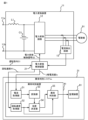
- the power conversion device 11 that supplies power to the electric motor 91 is, for example, a DC-to-three-phase conversion device that is mounted on a railway vehicle that uses a DC power supply and converts the DC power supplied from a power source into three-phase AC power and supplies it to the electric motor 91.
- a DC-to-three-phase conversion device that is mounted on a railway vehicle that uses a DC power supply and converts the DC power supplied from a power source into three-phase AC power and supplies it to the electric motor 91.
- one electric motor 91 is shown in FIG. 1, but the number of electric motors 91 to which the power conversion device 11 supplies power is arbitrary.
- the power conversion device 11 has an input terminal 11a connected to a power source and an input terminal 11b grounded.
- the power conversion device 11 further has a power conversion circuit 12 that converts DC power supplied from the power source into three-phase AC power and supplies the three-phase AC power to the electric motor 91.
- the power conversion device 11 is provided with a current detection circuit 13 that measures the current flowing from the power conversion device 11 to the electric motor 91.
- the power conversion device 11 further has a reactor L1 and a capacitor C1 that are connected in series between the input terminals 11a and 11b.
- the input terminal 11a is electrically connected to a power source, specifically, a collector that acquires power supplied from a substation via a power supply line, via a contactor, circuit breaker, etc. (not shown).
- a collector that acquires power supplied from a substation via a power supply line, via a contactor, circuit breaker, etc.
- the collector is a pantograph that acquires power via an overhead line, which is an example of a power supply line, or a collector shoe that acquires power via a third rail, which is an example of a power supply line.
- the input terminal 11b is grounded via a ground ring, ground brush, wheel, etc. (not shown).
- the power conversion circuit 12 is, for example, an inverter in which the effective voltage and frequency of the output AC power are variable.
- the power conversion circuit 12 has a plurality of switching elements.
- Each switching element is, for example, an IGBT (Insulated Gate Bipolar Transistor), a GTO (Gate Turn-Off thyristor), a MOSFET (Metal-Oxide-Semiconductor Field-Effect Transistor), etc.
- the current detection circuit 13 has an electric circuit between the power conversion circuit 12 and the motor 91, for example a CT (Current Transformer) attached to a bus bar electrically connecting the power conversion circuit 12 and the motor 91, and measures the phase currents output by the power conversion circuit 12, specifically the U-phase current, V-phase current, and W-phase current.
- the current detection circuit 13 sends the measured values of each phase current to the power conversion control device 21.
- reactor L1 is connected to input terminal 11a.
- the other end of reactor L1 is connected to the primary terminal of power conversion circuit 12.
- One end of capacitor C1 is connected to the connection point between the other end of reactor L1 and the primary terminal of power conversion circuit 12.
- the other end of capacitor C1 is connected to the connection point between input terminal 11b and the primary terminal of power conversion circuit 12.
- Reactor L1 and capacitor C1 form an LC filter that attenuates harmonic components generated by the switching operation of power conversion circuit 12.
- the power conversion control device 21 controls the switching operation of each switching element of the power conversion circuit 12 provided in the power conversion device 11.
- the power conversion control device 21 acquires a driving command S1 from a cab (not shown).
- the driving command S1 indicates a command corresponding to the operation of the driver on a master controller provided in the cab.
- the driving command S1 indicates any one of a powering command that instructs the railway vehicle to accelerate, a braking command that instructs the railway vehicle to decelerate, and a coasting command that instructs the railway vehicle to coast.
- a coasting command refers to a state in which neither a powering command nor a braking command has been input.
- the power conversion control device 21 generates a power conversion control signal S2 that controls each switching element of the power conversion circuit 12 in response to the operation command S1, and outputs the power conversion control signal S2 to the power conversion circuit 12.
- the power conversion control signal S2 is, for example, a PWM (Pulse Width Modulation) signal.
- the power conversion control device 21 obtains a target torque, which is a target value of the torque of the electric motor 91, from the target acceleration of the railway vehicle indicated by the powering command.
- the power conversion control device 21 estimates the rotation speed of the electric motor 91 from the U-phase current value, V-phase current value, and W-phase current value acquired from the current detection circuit 13.
- the power conversion control device 21 obtains a voltage command value from the estimated rotation speed of the electric motor 91 and the target torque, and generates a PWM signal from the voltage command value and a carrier wave obtained from a local oscillator (not shown).
- the abnormality determination system 31 that determines whether or not there is an abnormality in the electric motor 91 described above includes an abnormality determination device 41 that determines whether or not there is an abnormality in the electric motor 91, and a monitoring device 61 that outputs the determination result obtained from the abnormality determination device 41.
- the abnormality determination device 41 includes a current acquisition unit 51 that acquires time domain current data indicating the current flowing from the power conversion device 11 to the electric motor 91, a rotation speed acquisition unit 52 that acquires the rotation speed of the electric motor 91, and a conversion unit 53 that generates frequency domain spectrum data from the current data.
- the abnormality determination device 41 includes an intensity determination unit 54 that determines, from the spectrum data, a sideband wave intensity, which is the intensity of a sideband wave that is a frequency component shifted from the power supply frequency of the power conversion device 11 by the rotation frequency of the electric motor 91, and an abnormality determination unit 55 that determines the presence or absence of an abnormality in the electric motor 91 from a determination criterion according to the sideband wave intensity and the rotation speed.
- the abnormality determination device 41 is installed in ground equipment, for example, an operation control center, and communicates with the power conversion control device 21 via a network.
- the current acquisition unit 51 acquires the value of the current flowing through the motor 91, specifically, the U-phase current value Iu of the phase currents detected by the current detection circuit 13, from the power conversion control device 21.
- the current acquisition unit 51 outputs the acquired U-phase current value to the conversion unit 53 as current data.
- the rotation speed acquisition unit 52 acquires the estimated rotation speed N1 of the electric motor 91 from the power conversion control device 21.
- the rotation speed acquisition unit 52 outputs the acquired rotation speed N1 to the strength determination unit 54 and the abnormality determination unit 55.
- the conversion unit 53 generates spectral data in the frequency domain by performing an FFT (Fast Fourier Transform) on the current data acquired from the current acquisition unit 51.
- the conversion unit 53 sends the generated spectral data to the intensity determination unit 54.
- the intensity determination unit 54 determines the rotation frequency of the motor 91 from the rotation speed obtained from the rotation speed acquisition unit 52.
- the intensity determination unit 54 determines the sideband wave intensity, which is the intensity of the sideband wave, which is a frequency component shifted from the power supply frequency of the power conversion device 11 by the rotation frequency of the motor 91, and the intensity of the frequency component of the power supply frequency, from the spectrum data obtained from the conversion unit 53.
- the intensity determination unit 54 determines the upper sideband wave intensity, which is the intensity of the upper sideband wave, which is a frequency component obtained by adding the rotation frequency of the motor 91 to the power supply frequency, and the lower sideband wave intensity, which is the intensity of the lower sideband wave, which is a frequency component obtained by subtracting the rotation frequency of the motor 91 from the power supply frequency.
- the intensity determination unit 54 sends the determined sideband wave intensity and the intensity of the frequency component of the power supply frequency to the abnormality determination unit 55.
- the abnormality determination unit 55 specifies the determination criteria used to determine whether or not there is an abnormality in the electric motor 91 according to the rotation speed acquired from the rotation speed acquisition unit 52, and determines whether or not there is an abnormality in the electric motor 91 based on the sideband wave intensity and the determination criteria according to the rotation speed.
- the abnormality determination unit 55 determines that there is an abnormality in the electric motor 91, it transmits the determination result indicating that there is an abnormality to the monitoring device 61.
- the abnormality determination unit 55 obtains the signal strength difference for each of the upper sideband wave and the lower sideband wave by subtracting the sideband wave strength from the strength of the frequency component of the power supply frequency.
- the abnormality determination unit 55 specifies a target range that includes a target value for the signal strength difference and changes according to the rotation speed acquired from the rotation speed acquisition unit 52.
- the abnormality determination unit 55 determines whether or not the signal strength difference is within the specified target range. If the signal strength difference is within the target range, it can be determined that no abnormality has occurred in the electric motor 91. On the other hand, if the signal strength difference is not within the target range, it can be determined that an abnormality has occurred in the electric motor 91.
- the monitoring device 61 When the monitoring device 61 receives a determination result indicating that an abnormality has occurred from the abnormality determination unit 55 included in the abnormality determination device 41, it outputs the determination result indicating that an abnormality has occurred in the electric motor 91, for example, by a screen display, audio output, or other method.
- the monitoring device 61 is provided in ground equipment, for example, an operation control center.
- the abnormality determination device 41 includes a processor 81, a memory 82, and an interface 83.
- the processor 81, the memory 82, and the interface 83 are connected to one another via a bus 80.
- the functions of each part of the abnormality determination device 41 are realized by software, firmware, or a combination of software and firmware.
- the software and firmware are written as programs and stored in the memory 82.
- the processor 81 reads and executes the programs stored in the memory 82 to realize the functions of each part described above.
- the memory 82 stores programs for executing the processing of each part of the abnormality determination device 41.
- Memory 82 may include, for example, non-volatile or volatile semiconductor memory such as RAM (Random Access Memory), ROM (Read-Only Memory), flash memory, EPROM (Erasable Programmable Read-Only Memory), EEPROM (Electrically Erasable and Programmable Read-Only Memory), magnetic disks, flexible disks, optical disks, compact disks, mini disks, DVDs (Digital Versatile Discs), etc.
- RAM Random Access Memory
- ROM Read-Only Memory
- flash memory flash memory
- EPROM Erasable Programmable Read-Only Memory
- EEPROM Electrical Erasable and Programmable Read-Only Memory
- magnetic disks flexible disks
- optical disks compact disks
- mini disks mini disks
- DVDs Digital Versatile Discs
- the abnormality determination device 41 is connected to the power conversion control device 21, the monitoring device 61, etc. via the interface 83.
- the interface 83 has an interface module that complies with one or more standards depending on the connection destination.
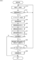
- the operation of the above-mentioned abnormality determination device 41 will be described with reference to FIG. 3.
- the current acquisition unit 51 included in the abnormality determination device 41 acquires current data indicating the value of the current flowing from the power conversion device 11 to the electric motor 91 from the power conversion control device 21 (step S11).
- the current acquisition unit 51 determines whether the electric motor 91 is operating or not from the electric current data (step S12). For example, if the amplitude of the electric current data is equal to or greater than an amplitude threshold determined according to the minimum value of the amplitude of the current supplied to the electric motor 91 after a certain time has elapsed since the electric motor 91 was driven, the electric motor 91 can be considered to be operating.
- step S11 When the electric motor 91 is not operating (step S12; No), the process of step S11 is repeated.
- the current acquisition unit 51 When the electric motor 91 is operating (step S12; Yes), the current acquisition unit 51 outputs the current data to the conversion unit 53, and the conversion unit 53 performs FFT on the current data to generate spectrum data (step S13).
- the rotational speed acquisition unit 52 acquires the rotational speed of the electric motor 91 from the power conversion control device 21 (step S14).
- the rotational speed acquisition unit 52 sends the acquired rotational speed to the intensity determination unit 54, which determines the rotational frequency from the rotational speed (step S15).
- the intensity determination unit 54 determines the sideband intensity from the spectrum data (step S16).
- the spectrum data includes peak values located at the power supply frequency and at a frequency shifted from the power supply frequency by the rotational frequency of the electric motor 91. Specifically, if the rotational frequency of the electric motor 91 is fr and the power supply frequency is f1, then peaks exist at frequencies (f1-fr), f1, and (f1+fr). In other words, the frequency components shifted by the rotational frequency fr to the left and right of the power supply frequency f1 are sidebands.
- the intensity determination unit 54 is assumed to hold in advance information about the power supply frequency f1 of the power conversion device 11 that supplies power to the electric motor 91 that is the target of abnormality determination.
- the power supply frequency f1 is constant at 50 Hz or 60 Hz.
- the intensity determination unit 54 determines the intensity of the sideband waves of the frequency (f1-fr) and the frequency (f1+fr) and the intensity of the frequency component of the power supply frequency f1 based on the power supply frequency f1 and the rotational frequency fr calculated from the rotational speed of the electric motor 91 obtained from the rotational speed acquisition unit 52.
- the intensity determination unit 54 outputs the calculated sideband wave intensity and the intensity of the frequency component of the power supply frequency f1 to the abnormality determination unit 55.
- the abnormality determination unit 55 determines the signal strength difference, which is the difference between the strength of the frequency component of the power supply frequency f1 and the sideband wave strength (step S17). In detail, the abnormality determination unit 55 determines the signal strength difference by subtracting the sideband wave strength from the strength of the frequency component of the power supply frequency f1 for each of the upper sideband wave and the lower sideband wave. As shown in FIG. 4, the strength of the frequency component of the power supply frequency f1 is higher than the sideband wave strength. When the sideband wave strength is higher relative to the strength of the frequency component of the power supply frequency f1, the signal strength difference becomes smaller. When the sideband wave strength is lower relative to the strength of the frequency component of the power supply frequency f1, the signal strength difference becomes larger.
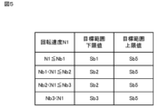
- the abnormality determination unit 55 determines whether the signal intensity difference is within the target range (step S18). In detail, the abnormality determination unit 55 identifies the target range from the rotation speed acquired from the rotation speed acquisition unit 52. In the first embodiment, as shown in FIG. 5, the abnormality determination unit 55 is assumed to previously store a correspondence between the rotation speed N1 and the upper and lower limits of the target range. In the example of the record in the first line of FIG. 5, if the rotation speed N1 is equal to or less than the reference value Nb1, the lower limit of the target range is Sb1, and the upper limit of the target range is Sb5. In other words, if the rotation speed N1 is equal to or less than the reference value Nb1 and the signal intensity difference is equal to or more than Sb1 and equal to or less than Sb5, the electric motor 91 can be considered to be normal.
- the abnormality determination unit 55 determines whether or not there is an abnormality in the motor 91 by comparing each signal strength difference with a target range according to the rotation speed.
- a target range according to the rotation speed In FIG. 6, the signal strength difference when the motor 91 can be considered normal is shown by a black circle, and the signal strength difference when the motor 91 can be considered abnormal is shown by a white circle.
- the range surrounded by a dotted line in FIG. 6 indicates the target range according to the rotation speed.
- step S18 when the abnormality determination unit 55 determines that the signal strength difference is outside the target range (step S18; No), it outputs a determination result indicating that an abnormality exists to the monitoring device 61 (step S19).
- the abnormality determination unit 55 determines that the signal strength difference is within the target range (step S18; Yes), it does not perform the process of step S19.
- the signal strength difference is within the target range (step S18; Yes), or when the process of step S19 is completed, the above-mentioned process is repeated from step S11.
- the abnormality determination device 41 determines whether or not there is an abnormality in the electric motor 91 based on the sideband wave intensity and a determination criterion according to the rotation speed. In detail, the abnormality determination device 41 determines whether or not there is an abnormality in the electric motor 91 based on whether or not the signal strength difference, which is the difference between the strength of the frequency component of the power supply frequency and the sideband wave intensity, is within a target range according to the rotation speed. By using a target range according to the rotation speed of the electric motor 91, it becomes possible to accurately determine whether or not there is an abnormality in the electric motor 91 based on the sideband wave intensity, which changes according to the rotation speed of the electric motor 91.
- the discrimination criteria used by the abnormality discrimination device to discriminate the presence or absence of an abnormality in the electric motor 91 are not limited to the above-mentioned examples.
- An abnormality discrimination device that discriminates the presence or absence of an abnormality in the electric motor 91 based on discrimination criteria according to the rotation speed and torque of the electric motor 91 will be described in the second embodiment, focusing on the differences from the first embodiment.
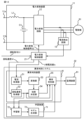
- the abnormality determination system 31 includes an abnormality determination device 42 that determines whether or not an abnormality exists in the electric motor 91, and a monitoring device 61 that outputs the determination result obtained from the abnormality determination device 42.
- the abnormality determination device 42 includes a torque acquisition unit 56 that acquires the torque of the electric motor 91.
- the hardware configuration of the abnormality determination device 42 is similar to the hardware configuration of the abnormality determination device 41 shown in FIG. 2.
- the torque acquisition unit 56 acquires the target torque ⁇ 1 used to control the power conversion circuit 12 from the power conversion control device 21.
- the torque acquisition unit 56 sends the acquired target torque to the abnormality determination unit 55.
- the abnormality determination unit 55 specifies a target range of the signal strength difference according to the rotation speed and the target torque, and determines whether or not there is an abnormality in the electric motor 91 by comparing the signal strength difference with the target range according to the rotation speed and the target torque.
- the abnormality determination unit 55 is assumed to previously store a correspondence between the rotation speed and the target torque and the upper and lower limits of the target range.
- the rotation speed N1 is equal to or less than the reference value Nb1 and the target torque ⁇ 1 is equal to or less than the reference value ⁇ b1
- the lower limit of the target range is Sb1
- the upper limit of the target range is Sb5.
- the electric motor 91 can be considered to be normal if the signal strength difference is equal to or greater than Sb1 and equal to or less than Sb5.
- the abnormality determination device 42 determines whether or not there is an abnormality in the electric motor 91 based on a comparison between the signal strength difference and a determination criterion according to the rotation speed and the target torque. In detail, the abnormality determination device 42 determines whether or not there is an abnormality in the electric motor 91 based on whether or not the signal strength difference is within a target range according to the rotation speed and the target torque. By using the target range according to the rotation speed and the target torque of the electric motor 91, it becomes possible to accurately determine whether or not there is an abnormality in the electric motor 91 based on the sideband wave intensity that changes according to the rotation speed and torque of the electric motor 91.
- the discrimination criteria used to discriminate the presence or absence of an abnormality in the electric motor 91 may be generated or updated by the abnormality discrimination device.
- the discrimination criteria an abnormality discrimination device that determines a target range according to the rotation speed will be described in the third embodiment, focusing on the differences from the first embodiment.
- the abnormality determination system 31 includes an abnormality determination device 43 that determines whether or not an abnormality exists in the electric motor 91, and a monitoring device 61 that outputs the determination result obtained from the abnormality determination device 43.
- the abnormality discrimination device 43 includes a discrimination criterion, specifically, a criterion determination unit 57 that determines a target range according to the rotation speed.
- the hardware configuration of the abnormality discrimination device 43 is the same as the hardware configuration of the abnormality discrimination device 41 shown in FIG. 2.
- the reference determination unit 57 acquires the rotation speed of the electric motor 91 from the rotation speed acquisition unit 52, and acquires the signal strength difference from the abnormality discrimination unit 55.
- the reference determination unit 57 stores the rotation speed and the signal strength difference in association with each other.
- the reference determination unit 57 determines a target range from the association between the rotation speed and the signal strength difference during the normal period from when the electric motor 91 starts operating until the period during which the electric motor 91 can be considered normal has elapsed.
- the reference determination unit 57 sends the determined target range to the abnormality discrimination unit 55.
- the reference determination unit 57 may store the rotation speeds of the respective electric motors 91 and the corresponding signal strength differences. In this case, the reference determination unit 57 may determine a common target range for the multiple electric motors 91 mounted on the same railcar.
- the abnormality determination unit 55 outputs the signal strength difference to the reference determination unit 57 and acquires the target range from the reference determination unit 57.
- the abnormality determination unit 55 determines whether or not there is an abnormality in the electric motor 91 by comparing the signal strength difference with the target range acquired from the reference determination unit 57.
- step S11 to step S16 are similar to the processes from step S11 to step S16 performed by the abnormality determination device 41 according to embodiment 1 shown in FIG. 3.
- the standard determination unit 57 determines whether or not the period is within a normal period from when the operation of the motor 91 starts until the period during which the motor 91 can be considered normal has elapsed (step S21).
- the normal period can be determined by test operation, simulation, etc. of the motor 91, and is a period during which the motor 91 can be considered to be operating normally without any breakdowns.
- step S21 If it is within the normal period (step S21; Yes), the reference determination unit 57 associates the rotation speed with the signal strength difference and stores them in a memory (not shown) (step S22).
- the standard determination unit 57 determines whether the number of stored data items correlating rotation speeds with signal strength differences is sufficient to determine the target range (step S23). If the number of data items is not sufficient (step S23; No), the above-described process is repeated from step S11.
- the reference determination unit 57 determines a target range from the correspondence between the stored rotation speed and the signal strength difference (step S24). For example, the reference determination unit 57 determines a target range that indicates the normal range of the signal strength difference according to the range of the rotation speed, taking the stored signal strength difference as the normal value.
- step S24 When the processing of step S24 is completed, or when a period during which the motor 91 can be considered normal has elapsed since the start of operation of the motor 91, i.e., when it is outside the normal period (step S21; No), the abnormality determination device 43 ends the criteria determination process.
- the abnormality determination device 43 performs the abnormality determination process shown in FIG. 3.
- the abnormality determination unit 55 determines whether or not there is an abnormality in the electric motor 91 by comparing the signal strength difference with the target range determined by the criteria determination unit 57.
- the abnormality determination device 43 determines the determination criteria for determining whether or not there is an abnormality in the electric motor 91. Therefore, it becomes possible to determine whether or not there is an abnormality in the electric motor 91 based on the determination criteria according to the rotation speed of the electric motor 91 according to the individual characteristics of the electric motor 91.
- the abnormality determination device may determine the presence or absence of a sign of an abnormality, in addition to determining the presence or absence of an abnormality in the electric motor 91.
- An abnormality determination device that determines the presence or absence of a sign of an abnormality will be described in a fourth embodiment, focusing on the differences from the first embodiment.
- the abnormality determination system 31 shown in FIG. 11 includes an abnormality determination device 44 that determines whether or not there is an abnormality or a sign of an abnormality in the electric motor 91, and a monitoring device 61 that outputs the determination result obtained from the abnormality determination device 44.
- the abnormality determination device 44 includes, in addition to the configuration of the abnormality determination device 41, a sign determination unit 58 that determines whether or not there is a sign of an abnormality.
- the hardware configuration of the abnormality determination device 44 is the same as the hardware configuration of the abnormality determination device 41 shown in FIG. 2.
- the sign discrimination unit 58 acquires the rotation speed of the electric motor 91 from the rotation speed acquisition unit 52, and acquires the signal strength difference from the abnormality discrimination unit 55.
- the sign discrimination unit 58 stores the correspondence between the rotation speed and the signal strength difference in a memory (not shown).
- the sign discrimination unit 58 discriminates whether there are signs of an abnormality in the motor 91 from the change over time in the signal strength difference within the target range over a period of time for which sign discrimination is to be performed.
- the period of time for which sign discrimination is to be performed is, for example, the period from when the motor 91 starts operating to the point at which it is determined whether there are signs of an abnormality.
- the sign discrimination unit 58 detects a change in which the signal strength difference suddenly approaches the lower limit of the target range, it determines that there are signs of an abnormality in the motor 91.
- the sign discrimination unit 58 determines that there is a sign of an abnormality in the electric motor 91, it transmits the discrimination result indicating that there is a sign of an abnormality to the monitoring device 61.
- the monitoring device 61 receives the discrimination result from the abnormality discrimination unit 55 or the discrimination result from the sign discrimination unit 58, it outputs the discrimination result.
- the abnormality determination device 44 makes it possible to determine whether there are signs of an abnormality in the electric motor 91 before an abnormality occurs in the electric motor 91. This makes it possible to prompt an operator to perform maintenance work on the electric motor 91 before an abnormality occurs in the electric motor 91.
- the discrimination criterion used to discriminate the presence or absence of an abnormality in the electric motor 91 may be obtained by a learning device.
- An abnormality discrimination system including a learning device will be described in a fifth embodiment, focusing on the differences from the first embodiment.
- the abnormality discrimination system 32 shown in FIG. 12 includes an abnormality discrimination device 41 that discriminates whether or not there is an abnormality in the electric motor 91, a monitoring device 61 that outputs the discrimination result obtained from the abnormality discrimination device 41, and a learning device 71 that obtains discrimination criteria used by the abnormality discrimination device 41 to discriminate whether or not there is an abnormality in the electric motor 91.
- the hardware configuration of the abnormality determination device 41 according to the fifth embodiment is the same as the hardware configuration of the abnormality determination device 41 according to the first embodiment shown in FIG. 2.
- the learning device 71 includes a learning unit 72 that learns the correspondence between rotation speed and signal strength difference, and a model generation unit 73 that generates an anomaly discrimination model from the correspondence between rotation speed and signal strength difference learned by the learning unit 72.
- the learning unit 72 acquires the rotation speed of the electric motor 91 from the rotation speed acquisition unit 52 included in the abnormality discrimination device 41.
- the learning unit 72 acquires the signal strength difference from the abnormality discrimination unit 55 included in the abnormality discrimination device 41.
- the learning unit 72 learns the correspondence between the rotation speed and the signal strength difference acquired as described above during the normal period from when the operation of the electric motor 91 starts until the period during which the electric motor 91 can be considered normal has elapsed.
- the model generation unit 73 obtains an anomaly discrimination model, which is a neural network model that receives the rotation speed and the signal strength difference as input and outputs the presence or absence of an anomaly in the electric motor 91, from the correspondence between the rotation speed and the signal strength difference learned by the learning unit 72.
- the model generation unit 73 sends the generated anomaly discrimination model to the anomaly discrimination unit 55 included in the anomaly discrimination device 41.
- the model generation unit 73 takes the rotation speed and the signal strength difference as input values and the presence or absence of an abnormality as output values, and generates a neural network model having an input layer, an intermediate layer, and an output layer.
- the correspondence between the rotation speed and the signal strength difference during a normal period learned by the learning unit 72 becomes the input value when the output value indicates that there is no abnormality in the electric motor 91.
- the model generation unit 73 adjusts the weights between the input layer and the intermediate layer, the weights between the intermediate layers, and the weights between the intermediate layer and the output layer based on the learning data consisting of the rotation speed and the signal strength difference.
- the abnormality determination unit 55 included in the abnormality determination device 41 determines whether or not there is an abnormality in the electric motor 91 by applying the rotation speed and the signal strength difference to the abnormality determination model obtained from the learning device 71.
- the abnormality discrimination system 32 generates, by the learning device 71, an abnormality discrimination model that serves as a discrimination criterion for discriminating abnormalities in the electric motor 91. Therefore, it becomes possible to determine whether or not there is an abnormality in the electric motor 91 based on a discrimination criterion according to the rotation speed of the electric motor 91, according to the individual characteristics of the electric motor 91.
- the abnormality determination unit 55 included in the abnormality determination devices 43 and 44 may determine whether or not there is an abnormality in the electric motor 91 by comparing the signal strength difference with a target range according to the rotation speed and target torque of the electric motor 91.
- the learning device 71 may learn the correspondence between the rotation speed, the target torque, and the signal strength difference during a normal period, and obtain an abnormality discrimination model that inputs the rotation speed, the target torque, and the signal strength difference and outputs the presence or absence of an abnormality in the electric motor 91.
- the learning unit 72 may learn the correspondence between the rotation speed and the target torque and the signal strength difference
- the model generation unit 73 included in the learning device 71 may generate an abnormality discrimination model from the correspondence between the rotation speed and the target torque and the signal strength difference.
- the abnormality determination device 41-44 may determine whether or not there is an abnormality in the motor 91 only when the disturbance strength is within an acceptable range.
- FIG. 13 shows the operation of the abnormality determination device 41 that determines whether or not there is an abnormality only when the disturbance strength is within an acceptable range.
- the processing from steps S11 to S19 in FIG. 13 is the same as the processing from steps S11 to S19 performed by the abnormality determination device 41 according to the first embodiment shown in FIG. 3.
- the intensity determination unit 54 determines the disturbance intensity from the spectrum data (step S31). In detail, the intensity determination unit 54 determines the disturbance intensity, which is the intensity of the frequency component between the power supply frequency and the frequency of the sideband wave.
- the intensity determination unit 54 determines whether the disturbance intensity is within an acceptable range (step S32).
- the acceptable range is determined according to the value that the disturbance intensity can take when the effect of the disturbance on the accuracy of determining whether or not there is an abnormality in the electric motor 91 based on the sideband intensity is sufficiently small.
- step S32 If the disturbance strength is within the allowable range (step S32; Yes), the strength determination unit 54 sends the strength of the sideband waves and the strength of the frequency component of the power supply frequency to the abnormality determination unit 55.
- the abnormality determination unit 55 performs subsequent processing as in the first embodiment. If the disturbance strength is outside the allowable range (step S32; No), the subsequent processing is not performed and the processing is repeated from step S11.
- the abnormality discrimination unit 55 provided in the abnormality discrimination device 41-44 may discriminate whether or not there is an abnormality in the motor 91 based on the number of times the signal strength difference exceeds the target range during a period subject to abnormality discrimination.
- the period subject to abnormality discrimination is, for example, the period from when operation of the motor 91 begins to when abnormality discrimination is made.
- the abnormality discrimination unit 55 may determine that an abnormality has occurred in the motor 91 when the number of times the signal strength difference exceeds the target range is equal to or greater than an abnormality threshold.
- the abnormality threshold is a value that can prevent a temporary fluctuation in sideband strength from erroneously determining that there is an abnormality in the motor 91.
- the current acquisition unit 51 may acquire the current value directly from the current detection circuit 13.
- the current acquisition unit 51 may acquire the V-phase current value or the W-phase current value.
- the conversion unit 53 may perform an FFT on the current data indicating the V-phase current value or the W-phase current value to generate spectrum data.
- the method of abnormality determination by the abnormality determination unit 55 is not limited to the above example, and may be any method as long as it can determine the presence or absence of an abnormality in the motor 91 from a determination criterion corresponding to the sideband wave intensity and the rotation speed.
- the abnormality determination unit 55 may determine the presence or absence of an abnormality in the motor 91 by comparing the sideband wave intensity with a target intensity range corresponding to the rotation speed.
- the abnormality determination unit 55 determines that no abnormality has occurred in the motor 91 if the sideband wave intensity is within the target intensity range, and determines that an abnormality has occurred in the motor 91 if the sideband wave intensity is outside the target intensity range.
- the criterion determination unit may determine the target intensity range, which is the range of target values for the sideband wave intensity, from the correspondence between the rotation speed and the sideband wave intensity.
- the abnormality determination unit 55 may determine whether or not there is an abnormality in the motor 91 by comparing the ratio of the sideband wave intensity to the intensity of the frequency component of the power supply frequency with a target ratio range according to the rotation speed.
- the reference determination unit can determine the target ratio range, which is the range of target values for the ratio, by correlating the rotation speed with the ratio of the sideband wave intensity to the intensity of the frequency component of the power supply frequency.
- the reference determination unit 57 may update the preset target range based on the correspondence between the rotation speed and the sideband wave strength.
- the determination of whether the electric motor 91 is operating in step S12 shown in FIG. 3 may be performed based on the rotation speed.
- the rotation speed may be obtained in step S14 in parallel with step S11.
- the rotation speed acquisition unit 52 may acquire the rotation speed of the electric motor 91 from a speed sensor that measures the rotation speed of the electric motor 91.
- the power conversion device 11, the power conversion control device 21, and the abnormality determination device 41 may be realized together as a power supply device 74.
- the power conversion device 11 is not limited to being mounted on railway vehicles using a DC power supply system, but can be mounted on any vehicle, such as railway vehicles using an AC power supply system or railway vehicles equipped with an internal combustion engine.
- a transformer that steps down the voltage of the AC power supplied from the current collector and a converter that converts the AC power stepped down by the transformer into DC power are provided.
- the power conversion device 11 converts the DC power supplied from the converter into AC power and supplies the converted AC power to the electric motor 91.
- the abnormality determination devices 41-44 may be implemented as one function of a train information management system.
- the abnormality determination devices 41-44 may not be mounted on the railway vehicle, but may be provided, for example, in a train operation control center.
- the motor 91 may be either a three-phase induction motor or a three-phase synchronous motor. Furthermore, the motor 91 is not limited to a three-phase motor, and may be, for example, a single-phase motor or a DC motor. The motor 91 may be an inner rotor or an outer rotor.
- the core part that has the processor 81, memory 82, and interface 83 and performs control processing can be realized using a normal computer system rather than a dedicated system.
- the computer program for performing the above-mentioned operations may be stored and distributed on a computer-readable recording medium (such as a flexible disk, a CD-ROM (Compact Disc-Read Only Memory), a DVD-ROM (Digital Versatile Disc-Read Only Memory), etc.), and the abnormality determination device 41-44 that performs the above-mentioned processing may be realized by installing the computer program on a computer.
- the abnormality determination device 41-44 may be realized by storing the computer program in a storage device of a server device on a communication network, and downloading it by a normal computer system.
- the functions of the abnormality determination devices 41-44 are realized by sharing the functions between an OS (Operating System) and an application program, or by collaboration between an OS and an application program, only the application program portion may be stored on a recording medium, storage device, etc.
- the computer program may be posted on a bulletin board system (BBS) on the communications network and distributed via the communications network.
- BSS bulletin board system
- the computer program may then be started and executed under the control of the OS in the same way as other application programs, thereby carrying out the above-mentioned processing.
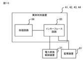
- the abnormality determination devices 41-44 may be realized by a processing circuit 84 as shown in FIG. 15.
- the processing circuit 84 is connected to the power conversion control device 21, the monitoring device 61, etc. via an interface circuit 85.
- the processing circuit 84 is dedicated hardware, the processing circuit 84 is, for example, a single circuit, a composite circuit, a programmed processor, a parallel programmed processor, an ASIC (Application Specific Integrated Circuit), an FPGA (Field Programmable Gate Array), or a combination of these.
- Each part of the abnormality determination devices 41-44 may be realized by a separate processing circuit 84, or each part of the abnormality determination devices 41-44 may be realized by a common processing circuit 84.
- the abnormality determination devices 41-44 may be realized by dedicated hardware, and other parts may be realized by software or firmware.
- the current acquisition unit 51 and rotation speed acquisition unit 52 of the abnormality determination device 41 may be realized by a processing circuit 84 shown in FIG. 15, and the conversion unit 53, strength determination unit 54, and abnormality determination unit 55 may be realized by the processor 81 shown in FIG. 2 reading and executing a program stored in memory 82.
Landscapes
- Physics & Mathematics (AREA)
- General Physics & Mathematics (AREA)
- Mathematical Physics (AREA)
- Electric Propulsion And Braking For Vehicles (AREA)
Priority Applications (2)
| Application Number | Priority Date | Filing Date | Title |
|---|---|---|---|
| JP2025533775A JP7805532B2 (ja) | 2023-07-18 | 2023-07-18 | 異常判別装置、電源装置、異常判別システムおよび異常判別方法 |
| PCT/JP2023/026309 WO2025017843A1 (ja) | 2023-07-18 | 2023-07-18 | 異常判別装置、学習装置、電源装置、異常判別システムおよび異常判別方法 |
Applications Claiming Priority (1)
| Application Number | Priority Date | Filing Date | Title |
|---|---|---|---|
| PCT/JP2023/026309 WO2025017843A1 (ja) | 2023-07-18 | 2023-07-18 | 異常判別装置、学習装置、電源装置、異常判別システムおよび異常判別方法 |
Publications (1)
| Publication Number | Publication Date |
|---|---|
| WO2025017843A1 true WO2025017843A1 (ja) | 2025-01-23 |
Family
ID=94281338
Family Applications (1)
| Application Number | Title | Priority Date | Filing Date |
|---|---|---|---|
| PCT/JP2023/026309 Pending WO2025017843A1 (ja) | 2023-07-18 | 2023-07-18 | 異常判別装置、学習装置、電源装置、異常判別システムおよび異常判別方法 |
Country Status (2)
| Country | Link |
|---|---|
| JP (1) | JP7805532B2 (https=) |
| WO (1) | WO2025017843A1 (https=) |
Citations (8)
| Publication number | Priority date | Publication date | Assignee | Title |
|---|---|---|---|---|
| JP2010288352A (ja) * | 2009-06-10 | 2010-12-24 | Nippon Steel Corp | 設備の異常診断方法 |
| JP2011257362A (ja) * | 2010-06-11 | 2011-12-22 | Takada Corp | 回転機械系の異常診断方法 |
| WO2017154091A1 (ja) * | 2016-03-08 | 2017-09-14 | 株式会社日立製作所 | 回転機の診断装置及び診断方法 |
| WO2018142569A1 (ja) * | 2017-02-03 | 2018-08-09 | 三菱電機株式会社 | 電動機の診断装置 |
| WO2020039661A1 (ja) * | 2018-08-23 | 2020-02-27 | 三菱電機株式会社 | 異常診断装置 |
| JP6824493B1 (ja) * | 2020-05-25 | 2021-02-03 | 三菱電機株式会社 | 電動機の診断装置 |
| WO2022102113A1 (ja) * | 2020-11-16 | 2022-05-19 | 三菱電機株式会社 | 電動機の診断装置 |
| JP7287591B1 (ja) * | 2022-09-20 | 2023-06-06 | 三菱電機株式会社 | 電動機の状態診断装置、状態診断方法および異常予兆推論装置 |
Family Cites Families (3)
| Publication number | Priority date | Publication date | Assignee | Title |
|---|---|---|---|---|
| DE112020007369T5 (de) | 2020-06-29 | 2023-05-04 | Mitsubishi Electric Corporation | Abnormalitätsdiagnosevorrichtung, leistungsumwandlungsvorrichtung undabnormalitätsdiagnosisverfahren |
| WO2022224391A1 (ja) | 2021-04-22 | 2022-10-27 | 三菱電機株式会社 | 異常診断装置及び異常診断方法 |
| JP7527500B2 (ja) | 2021-11-25 | 2024-08-02 | 三菱電機株式会社 | 電動機の診断装置および診断方法 |
-
2023
- 2023-07-18 WO PCT/JP2023/026309 patent/WO2025017843A1/ja active Pending
- 2023-07-18 JP JP2025533775A patent/JP7805532B2/ja active Active
Patent Citations (8)
| Publication number | Priority date | Publication date | Assignee | Title |
|---|---|---|---|---|
| JP2010288352A (ja) * | 2009-06-10 | 2010-12-24 | Nippon Steel Corp | 設備の異常診断方法 |
| JP2011257362A (ja) * | 2010-06-11 | 2011-12-22 | Takada Corp | 回転機械系の異常診断方法 |
| WO2017154091A1 (ja) * | 2016-03-08 | 2017-09-14 | 株式会社日立製作所 | 回転機の診断装置及び診断方法 |
| WO2018142569A1 (ja) * | 2017-02-03 | 2018-08-09 | 三菱電機株式会社 | 電動機の診断装置 |
| WO2020039661A1 (ja) * | 2018-08-23 | 2020-02-27 | 三菱電機株式会社 | 異常診断装置 |
| JP6824493B1 (ja) * | 2020-05-25 | 2021-02-03 | 三菱電機株式会社 | 電動機の診断装置 |
| WO2022102113A1 (ja) * | 2020-11-16 | 2022-05-19 | 三菱電機株式会社 | 電動機の診断装置 |
| JP7287591B1 (ja) * | 2022-09-20 | 2023-06-06 | 三菱電機株式会社 | 電動機の状態診断装置、状態診断方法および異常予兆推論装置 |
Also Published As
| Publication number | Publication date |
|---|---|
| JPWO2025017843A1 (https=) | 2025-01-23 |
| JP7805532B2 (ja) | 2026-01-23 |
Similar Documents
| Publication | Publication Date | Title |
|---|---|---|
| US7768220B2 (en) | Harmonic torque ripple reduction at low motor speeds | |
| US8138712B2 (en) | Motor drive system and its control method | |
| JP5003589B2 (ja) | 短絡相特定方法 | |
| US9007005B2 (en) | Inverter controlling system and method for reducing noise in eco-friendly vehicle | |
| JP4788975B2 (ja) | 回転電機制御システム及び車両駆動システム | |
| US20140091743A1 (en) | Control device for ac motor | |
| US8487559B2 (en) | Diesel-electric drive system | |
| EP3905511A1 (en) | Drive device for dynamo-electric machine, and method for driving | |
| US9960726B1 (en) | Electric drive power converter with low distortion dead-time insertion | |
| KR20200119949A (ko) | 레졸버 신호를 이용한 모터 구동 시스템의 고장진단 장치 및 방법 | |
| JP2013090401A (ja) | 回転電機制御システム | |
| KR20100055281A (ko) | 철도차량용 npc형 3-레벨 인버터의 과변조 제어 방법 | |
| JP7499996B2 (ja) | 駆動装置および劣化判別方法 | |
| JP7805532B2 (ja) | 異常判別装置、電源装置、異常判別システムおよび異常判別方法 | |
| JP6699481B2 (ja) | モータの駆動装置 | |
| US12062997B2 (en) | Control device and motor drive system | |
| JP5899787B2 (ja) | 回転電機制御システム | |
| US11674459B2 (en) | Control apparatus, vehicle system, and control method | |
| US11325478B2 (en) | Control apparatus, vehicle system, and control method | |
| JP2013158091A (ja) | 回転電機制御システム | |
| US11396236B2 (en) | Electric vehicle control device | |
| JP7599615B2 (ja) | 劣化判別装置および劣化判別方法 | |
| WO2025196859A1 (ja) | 劣化診断装置、学習装置、電源装置および劣化診断システム | |
| JP6221824B2 (ja) | 電力変換器の制御装置 | |
| CN118077137A (zh) | 旋转电机的控制装置及电动助力转向装置 |
Legal Events
| Date | Code | Title | Description |
|---|---|---|---|
| 121 | Ep: the epo has been informed by wipo that ep was designated in this application |
Ref document number: 23945846 Country of ref document: EP Kind code of ref document: A1 |
|
| ENP | Entry into the national phase |
Ref document number: 2025533775 Country of ref document: JP Kind code of ref document: A |
|
| WWE | Wipo information: entry into national phase |
Ref document number: 2025533775 Country of ref document: JP |
|
| NENP | Non-entry into the national phase |
Ref country code: DE |