WO2025017834A1 - 治療器具 - Google Patents
治療器具 Download PDFInfo
- Publication number
- WO2025017834A1 WO2025017834A1 PCT/JP2023/026284 JP2023026284W WO2025017834A1 WO 2025017834 A1 WO2025017834 A1 WO 2025017834A1 JP 2023026284 W JP2023026284 W JP 2023026284W WO 2025017834 A1 WO2025017834 A1 WO 2025017834A1
- Authority
- WO
- WIPO (PCT)
- Prior art keywords
- bone cement
- hole
- internal fixation
- tip
- driver
- Prior art date
- Legal status (The legal status is an assumption and is not a legal conclusion. Google has not performed a legal analysis and makes no representation as to the accuracy of the status listed.)
- Pending
Links
Images
Classifications
-
- A—HUMAN NECESSITIES
- A61—MEDICAL OR VETERINARY SCIENCE; HYGIENE
- A61B—DIAGNOSIS; SURGERY; IDENTIFICATION
- A61B17/00—Surgical instruments, devices or methods
- A61B17/56—Surgical instruments or methods for treatment of bones or joints; Devices specially adapted therefor
- A61B17/58—Surgical instruments or methods for treatment of bones or joints; Devices specially adapted therefor for osteosynthesis, e.g. bone plates, screws or setting implements
- A61B17/68—Internal fixation devices, including fasteners and spinal fixators, even if a part thereof projects from the skin
- A61B17/84—Fasteners therefor or fasteners being internal fixation devices
- A61B17/86—Pins or screws or threaded wires; nuts therefor
-
- A—HUMAN NECESSITIES
- A61—MEDICAL OR VETERINARY SCIENCE; HYGIENE
- A61B—DIAGNOSIS; SURGERY; IDENTIFICATION
- A61B17/00—Surgical instruments, devices or methods
- A61B17/56—Surgical instruments or methods for treatment of bones or joints; Devices specially adapted therefor
- A61B17/58—Surgical instruments or methods for treatment of bones or joints; Devices specially adapted therefor for osteosynthesis, e.g. bone plates, screws or setting implements
- A61B17/88—Osteosynthesis instruments; Methods or means for implanting or extracting internal or external fixation devices
- A61B17/92—Impactors or extractors, e.g. for removing intramedullary devices
Definitions
- the present invention relates to a medical treatment device for operating a cylindrical internal fixation device, and is particularly suitable for use in internal fixation surgery of the affected vertebral body.
- Vertebroplasty and spinal fixation are known as treatments for compression fractures of the spine.
- the spine consists of stacked vertebral bodies and the vertebral arch, pedicle, articular process, etc. that support them.
- the vertebral body is a cylindrical bone that sandwiches the nucleus pulposus and the annulus fibrosus that surrounds it from above and below, and is supported by two pedicles extending from the vertebral arch.
- the vertebral arches are connected above and below by the upper and lower articular processes, and support the vertebral bodies via the pedicles to form the spine.
- Compression fractures are diseases in which the vertebral body is crushed and damaged by vertical compression.
- Vertebroplasty is a surgery to reconstruct the crushed vertebral body, and a surgical procedure is used in which, for example, medical cement is filled into the vertebral body.
- Spinal fixation is a procedure in which the crushed vertebral body and the healthy vertebral bodies above and below it are fixed with instruments. Screws are screwed into the crushed vertebral body and the healthy vertebral bodies above and below it from the pedicle, and the heads of the screws are connected to rods that are crossed above and below each other to fix them. If symptoms are mild, vertebroplasty is performed, but if symptoms are severe, spinal fusion surgery is required.
- Patent Document 1 discloses a medical screw with a longitudinal through-hole along the central axis and a side opening that communicates with the through-hole.
- An injection device such as a syringe is attached to the head of the screw, and bone cement or a physiologically activating substance is injected from the through-hole through the side opening into the surrounding bone, reinforcing the surrounding bone ([0053]-[0057], Figs. 6-8).
- Patent Document 2 discloses a medical screw that can be easily removed from the fracture site into which it has been screwed.
- the medical screw has a hollow section formed from the head to the tip along the central axis, with a screw thread formed on the side, and is screwed into the bone.
- a reverse thread (reverse internal thread) is provided near the inside tip of the hollow section of the screw, and it can be removed by using a removal tool with a tip that engages with the reverse internal thread. More specifically, the removal tool is inserted from the hollow section and its tip is meshed and integrated with the reverse internal thread of the screw, and the removal tool is then rotated to remove the screw from the body.
- the inventors have discovered a problem in that medical instruments and screws suitable for the above-mentioned procedure of combining vertebroplasty and pedicle plasty have not been sufficiently developed.
- This invention is a treatment device that is integrated with a screw that has a through hole along the central axis and a tappable thread on the side, and is configured so that, with a driver connected to the head of the screw, bone cement can be injected into the affected area through the through hole of the screw, and then the screw can be screwed into the bone cement. After injecting the bone cement, there is no need to attach the driver again, and the driver can be operated as is, so the screw can be screwed in quickly before the bone cement hardens.
- the removal tool described in Patent Document 2 can strongly connect the screw and the driver and transmit a strong force to the screw, which helps removal when the screw is surrounded by body tissues such as the patient's bones, but when the bond between the bone cement and the screw is stronger than the adhesion between the bone cement and the surrounding body tissues such as bones, as described above, there is a risk that the bone cement will separate from the surrounding body tissues instead of the screw coming out of the bone cement, and this does not help removal.
- the internal fixation device of this invention is an alternative to the above-mentioned screw, and has a groove rather than a screw thread formed in the part that is inserted into the bone cement.
- a screw thread When a screw thread is inserted into the bone cement, it pushes the surrounding bone cement apart as it advances, leaving no gaps, whereas the bone cement only penetrates into the groove due to its viscosity, leaving gaps, or even if no gaps are formed, the adhesion to the bone cement is weak. As a result, it can be removed with little force.
- an internal fixation device refers to a device that is inserted from the pedicle into the bone cement inside the vertebral body and supports and fixes the bone cement inside the vertebral body from the pedicle side, and is redefined as a device that includes the above-mentioned screw.
- the inventor has realized that there is a further new problem.
- an internal fixation device When inserting an internal fixation device into bone cement, it is generally screwed in using the tapping thread (at least the thread on the head side for screwing into the pedicle), but when removing the internal fixation device, it is rotated in the opposite direction to when it was screwed in.
- the bond between the internal fixation device and the bone cement is stronger than the adhesion between the bone cement and the affected tissues such as the surrounding bone, there is a problem in that the bone cement cannot be rotated and removed.
- the object of the present invention is to provide a treatment device that assists in the removal of an internal fixation device that is inserted from the pedicle into bone cement that has been previously filled into the vertebral body.
- the treatment device includes a bone cement molding device and a bone cement fixing device, which are inserted into an internal fixation device that supports and fixes the bone cement filled in the vertebral body from the pedicle, and is configured as follows:
- the internal fixation device has a through hole in the central axis direction from the head to the tip, and can be inserted into the bone cement along its central axis and removed.
- the bone cement molding device is inserted into the bone cement through the through hole of the internal fixation device to mold a hole of a specified shape.
- the bone cement fixing device has a tip that is inserted into the hole molded above, and by inserting the tip into the hole through the through hole of the internal fixation device, the rotation and/or movement of the bone cement in the withdrawal direction is suppressed.
- FIG. 1 is an explanatory view showing a schematic cross-sectional structure of a configuration example of a treatment instrument of the present invention including a bone cement molding instrument.
- FIG. 2 is an explanatory view showing a schematic cross-sectional structure of a configuration example of the treatment instrument of the present invention including the bone cement fixing instrument.
- FIG. 3 is an explanatory diagram showing the bottom surface of each of the tip portions (square shape) of the bone cement molding instrument and the bone cement fixing instrument as viewed from the proximal end side, in order to show a first configuration example.
- FIG. 4 is an explanatory diagram showing the bottom surface of each of the tip portions (star-shaped) of the bone cement molding instrument and the bone cement fixing instrument as viewed from the proximal end side, to show a third configuration example.
- FIG. 5 is an explanatory diagram showing the external appearance and cross-sectional structure of the distal end portion of each of the bone cement molding instrument and the bone cement fixing instrument, in order to show a first configuration example.
- FIG. 6 is an explanatory diagram showing a bottom view and a cross-sectional structure of the tip portion of each of the bone cement molding instrument and the bone cement fixing instrument, in order to show a second configuration example.
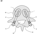
- FIG. 7 is an explanatory diagram showing an example of use of the internal fixation device according to the present invention from a bird's-eye view.
- FIG. 8 is a top view, a front view, and a bottom view showing a configuration example of an internal fixation device according to the present invention.
- FIG. 8 is a top view, a front view, and a bottom view showing a configuration example of an internal fixation device according to the present invention.
- FIG. 9 is an explanatory diagram showing a schematic cross-sectional structure to show an example of the configuration of a treatment device according to the present invention.
- FIG. 10 is an explanatory diagram that shows a schematic diagram of the first half of the procedure for embedding an internal fixation device in a treatment using the treatment device of the present invention.
- FIG. 11 is an explanatory diagram that shows a schematic example of the latter half of the procedure for embedding an internal fixation device in a treatment using the treatment device of the present invention.
- FIG. 12 is an explanatory diagram that shows a schematic diagram of another example of the latter half of the procedure for embedding an internal fixation device in a treatment using the treatment device of the present invention.
- FIG. 10 is an explanatory diagram that shows a schematic diagram of the first half of the procedure for embedding an internal fixation device in a treatment using the treatment device of the present invention.
- FIG. 11 is an explanatory diagram that shows a schematic example of the latter half of the procedure for embedding an internal fix
- FIG. 13 is an explanatory diagram that illustrates an example of a procedure for removing an internal fixation device during treatment using the treatment device of the present invention.
- FIG. 14 is an explanatory diagram that illustrates a schematic diagram of another example of a procedure for removing an internal fixation device during treatment using the treatment device of the present invention.
- FIG. 15 is an explanatory diagram showing the bottom surface of each tip portion (cross-shaped) viewed from the proximal end side to show the fourth configuration example of the bone cement molding instrument and the bone cement fixing instrument.
- FIG. 16 is an explanatory diagram showing the external appearance and cross-sectional structure of the distal end of each of the bone cement molding instrument and the bone cement fixing instrument, in order to show the fifth configuration example.
- FIG. 17 is an explanatory diagram showing the external appearance and cross-sectional structure of the tip portion of each of the bone cement molding instrument and the bone cement fixing instrument, in order to show the sixth configuration example.
- FIG. 18 is an explanatory view that illustrates an example of a procedure for removing an internal fixation device during treatment using the treatment device of the third embodiment of the present invention.
- FIG. 19 is an explanatory view that illustrates a schematic diagram of another example of the procedure for removing the internal fixation device during treatment using the treatment device of the third embodiment of the present invention.
- FIG. 20 is an explanatory diagram that shows a schematic configuration example of a bone cement molding instrument and a driver according to the treatment instrument of the fourth and fifth embodiments of the present invention.
- FIG. 21 is an explanatory diagram that illustrates the latter half of the procedure for embedding an internal fixation device during treatment using the treatment device of the fifth embodiment.
- FIG. 22 is an explanatory view that illustrates an example of a procedure for removing an internal fixation device during treatment using the treatment device of the sixth embodiment of the present invention.
- Bone cement is a medical cement that contains, for example, calcium phosphate and polymethylmethacrylate as its main components, and hardens over time.
- a representative embodiment disclosed in the present application is a treatment device (100) including a bone cement molding device (50) and a bone cement fixing device (60) that are inserted into an internal fixation device (10) that supports and internally fixes bone cement filled in a vertebral body from the pedicle, and is configured as follows.
- the internal fixation device has a through hole (16) in the central axis direction from the head (13) to the tip, and can be inserted into and removed from the bone cement (1) along the central axis.
- the bone cement molding tool is inserted into the bone cement through the through hole of the internal fixation tool to mold a hole (2) of a predetermined shape.
- the bone cement fixing device has a tip (61) that is inserted into the hole, and is inserted through the through hole of the internal fixation device into the bone cement (1) in which the hole is formed, and the tip is inserted into the hole, thereby suppressing the rotation of the bone cement around the central axis and/or movement in the pull-out direction.
- the tapping screw of the bone cement fixation device is screwed into the circular hole to fix it ( Figures 16 and 17).
- the tip of the bone cement molding instrument is cylindrical (Fig. 16) or tapered (Fig. 17) with a diameter decreasing toward the tip.
- a cylindrical or tapered hole (2) with a diameter decreasing toward the depth is formed.
- the bone cement fixing instrument has a screw thread that is screwed into the side wall of the hole by tapping.
- the bone cement molding tool also has a thread for tapping the side wall (Fig. 20)
- the bone cement molding instrument has a screw thread (54) that taps and screws into the side wall of the hole.
- the treatment instrument (100) further includes a driver (20), the internal fixation instrument is connectable to the driver at a head (13), and the driver has a through hole that communicates with the through hole of the internal fixation instrument when connected to the internal fixation instrument and allows the tip portions of the bone cement molding instrument and the bone cement fixing instrument to pass through.
- This provides a driver (20) that can be used both in surgery to screw in the internal fixation device (10) and in surgery to remove it.
- the bone cement molding tool can be connected to a driver ( Figure 20)
- the bone cement molding instrument is inserted into the through hole of the driver connected to the internal fixation instrument, and protrudes a predetermined length from the tip of the internal fixation instrument.
- the bone cement molding tool and the driver are integrated with a screw ( Figure 20)
- the driver has a screw structure (53) at a distal end that can be connected to the bone cement molding instrument.
- the handle of the bone cement fixation device can be attached and detached ( Figure 14)
- the bone cement fixing instrument has a structure in which the handle portion (62) and the shaft portion are removable.
- the treatment device further includes a guide pin (40), and the bone cement fixing device has a through hole (64) through which the guide pin can pass.
- a bone cement fixing device that abuts against the side wall of a square hole to suppress the rotation of the bone cement ( Figure 5)
- the tip of the bone cement molding instrument is a rectangular column (Fig. 5(a)) or a rectangular column tapered type (Fig. 5(b)) whose cross section becomes smaller in the direction of the tip, and a rectangular column-shaped or rectangular column tapered type hole (2) whose cross section becomes smaller in the direction of the depth is formed.
- the bone cement fixing instrument has a tip shape that can abut against the side wall of the hole to suppress the rotation of the bone cement.
- the handle of the bone cement fixation device can be attached and detached ( Figure 14)
- the bone cement fixing instrument has a structure in which the handle portion (62) and the shaft portion are detachable.
- the treatment instrument further includes a driver, the internal fixation instrument is connectable to the driver at a head portion, and the driver has a through hole that communicates with the through hole of the internal fixation instrument when connected to the internal fixation instrument and allows the tip portions of the bone cement molding instrument and the bone cement fixing instrument to pass through.
- This provides a driver (20) that can be used both in surgery to screw in the internal fixation device (10) and in surgery to remove it.
- the treatment device further includes a guide pin (40), and the bone cement fixing device has a through hole (64) through which the guide pin can pass.
- FIG. 7 is an explanatory diagram showing an example of using the internal fixation device 10 from a bird's-eye view.
- the spine is composed of a plurality of vertebral bodies 90 stacked vertically, and Fig. 7 shows one of the vertebral bodies 90 as seen through from above and below.
- the vertebral body 90 is supported by a pair of left and right pedicles 91, which are connected by a vertebral arch 92.
- the part surrounded by the vertebral bodies 90, the pedicles 91, and the vertebral arch 92 is the spinal canal 93.
- a compression fracture is a disease in which a vertebral body is compressed and collapsed by a force in the vertical direction.
- a space is returned to the vertebral body 90, bone cement 1 is injected, and the internal fixation device 10 is inserted (screwed) before the bone cement hardens, and the pedicle 91 side is supported.
- the internal fixation device 10 is inserted from the pedicle 91 into the bone cement 1 filled in the vertebral body 90 in advance, and when the bone cement 1 hardens, it is supported by the internal fixation device 10 from the pedicle 91 and fixed in the vertebral body 90.
- the internal fixation device 10 is an instrument that is screwed into the bone cement 1 in the vertebral body 90 while tapping a bone hole formed in the pedicle 91, and may be, for example, a conventional screw as described in Patent Document 1, but the tip side that is embedded in the bone cement 1 does not necessarily need to have a tapping thread.
- FIGS. 8A, 8B, and 8C are top and front and bottom views showing an example of the configuration of an easily removable internal fixation device 10, which was internationally filed as PCT/JP2023/22593.
- the back view and the left and right side views are omitted because they are the same as the front view (b) except that the groove 14 and the screw thread 15 are arranged at a position extended from the front view (b).
- the internal fixation device 10 comprises a cylindrical shaft 12 and a connection part 13 at the distal end of the shaft 12 that can be connected to a driver, and the shaft 12 has a spiral groove 14 on the proximal side.
- the shaft 12 is preferably cylindrical and has a through hole 16 that penetrates from the distal end to the proximal end along the central axis.
- the through hole 16 can be passed through, for example, a guide pin.
- the through hole 16 may also be configured to be able to pass through a bone drilling instrument, a balloon catheter, a bone cement injector, or the like.
- the connection part 13 of the head is configured as a hexagonal column-shaped recess to engage with a hexagonal wrench, for example, so that the entire internal fixation device 10 can be rotated by engaging with a driver (not shown).
- a driver not shown in FIG.
- a hexagonal column-shaped head (connection part) is shown as an example assuming connection with a hexagonal wrench-shaped driver head, but this shape is arbitrary as long as it can transmit rotational force, and may be changed to, for example, a star, triangle, square, or cross shape.
- the reference numeral 13 may be referred to as the "head” with emphasis on its position in the internal fixation device 10, or as the "connection part” with emphasis on its function of connecting with a driver.
- the depth of the groove 14 of the internal fixation device 10 may be uniform, but it is more preferable to make the proximal side (tip side) of the shaft 12 deeper than the distal side (head side).
- the proximal side (tip side) that comes into contact with the bone cement 1 first is deeper, so the bone cement 1 penetrates deeper into the groove 14, and as it is screwed in, it is sent along the spiral of the groove 14 to the shallower distal side (head side) of the groove 14, so the bone cement 1 smoothly penetrates into the groove 14 and is firmly fixed.
- the internal fixation device 10 when removing the internal fixation device 10, it rotates in the opposite direction along the spiral of the groove 14 while being separated from the bone cement 1, so the force required for removal can be reduced.
- the shaft 12 of the internal fixation device 10 has a tapered section 17 whose diameter gradually decreases from the center toward the proximal end.
- the distal side (head side) of the shaft 12 of the internal fixation device 10 may be provided with a screw thread 15.
- the screw thread 15 is a helical convex portion that protrudes outward from the outer circumferential surface of the shaft 12, and has the function of tapping the surrounding bone and moving the internal fixation device 10 (shaft 12) along the central axis as it rotates.
- the screw thread 15 taps the pedicle 91 and advances, firmly fixing the internal fixation device 10 and stably supporting the bone cement 1 inside the vertebral body 90 into which the shaft 12 is inserted.
- the threads 15 and grooves 14 are preferably formed with equal leads.
- the lead is the distance traveled along the central axis relative to the amount of rotation of the shaft 12, and it is desirable that the distance traveled by the shaft 12 while the threads 15 tap the pedicle 91 matches the distance traveled by the shaft 12 along the spiral of the groove 14 when screwed into the bone cement 1.
- precise matching is not necessarily required, and they can be made different intentionally.
- a force can be applied to move the bone cement 1 closer to the pedicle as the internal fixation device 10 (shaft 12) rotates.
- the number of threads can be different between the groove 14 and the thread 15.
- the number of threads in the groove 14 can be smaller than the number of threads in the thread 15. This allows the bonding force between the internal fixation device 10 and the bone cement 1 to be appropriately designed while strengthening the fixation to the pedicle 91 by the thread 15.
- the fixation of the internal fixation device 10 to the pedicle 91 can be strengthened.
- the relationship between the bone cement 1 and the groove 14 and the relationship between the pedicle 91 and the thread 15 can be independently optimized.
- the term "internal fixation device” refers to a device that is inserted from the pedicle into bone cement that has been filled in the vertebral body beforehand, and that is fixed from the pedicle into the vertebral body when the bone cement hardens. Therefore, the internal fixation device in this specification includes not only the easily removable internal fixation device 10 that was internationally filed as PCT/JP2023/022593, but also those without grooves 14, those without threads 15, those without both grooves 14 and threads 15, and even conventional screws with threads formed all over.
- FIG. 9 is an explanatory diagram showing a schematic cross-sectional structure of a treatment instrument 100 to show an example of its configuration.
- the treatment instrument 100 includes a cylindrical driver 20 that can screw the internal fixation device 10 into bone, and an inner cylinder 30 that is inserted into the driver 20, and is configured as follows.
- the internal fixation device 10 has a blunt tip so that a soft vertebral excavation device such as a balloon can be inserted and removed, and has a screw thread 15 that can tap bone or cement on the outer wall, and a through hole 16 that can pass the inner tube 30 from the head 13 to the tip along the central axis.
- the driver 20 is fitted into the head 13 of the internal fixation device 10 by moving it along the central axis, and is connected to the internal fixation device 10, and is configured to be able to transmit a rotational force around the central axis to the internal fixation device 10.
- the tip of the driver 20 may be formed in the shape of a hexagonal wrench (hexagonal column), and the head 13 of the internal fixation device 10 may be formed with a hexagonal groove (recess).
- the shape of the driver tip and the shape of the screw head only need to be inserted and engaged, and may be a shape other than a hexagon, such as a star shape.
- the inner tube 30 is inserted from the distal end of the driver 20 through the through holes of the driver 20 and the internal fixation device 10, and has a tip portion 32 that protrudes proximally beyond the tip of the internal fixation device 10. With the tip portion 32 protruding proximally beyond the tip of the internal fixation device 10, the inner tube 30 is connected and integrated with the internal fixation device 10 and the driver 20, improving operability such as screwing the internal fixation device 10. Furthermore, by inserting the guide pin 40, the integration is strengthened, and the inner tube 30 cannot be pulled out of the internal fixation device 10 and the driver 20.
- the tip 32 of the inner tube 30 is divided into multiple tongues 31 in the direction along the central axis, and each of the multiple tongues 31 has a protrusion 33 in the direction away from the central axis.
- the protrusion 33 has a notch function to prevent the internal fixation device 10 from slipping out of the inner tube 30 as described below, so the symbol 33 is referred to as a notch.
- the multiple tongues 31 are formed, for example, by dividing the cylindrical inner tube 30 from the tip side with slits. The number of divisions is arbitrary, for example, 4 divisions, 6 divisions, 2 divisions, 3 divisions, etc.
- some processing for example, heat treatment, processing to reduce the thickness, processing to bond a metal with high elasticity
- the elasticity of the tongues 31 is designed to have appropriate bending. For example, when the inner tube 30 passes through the through hole of the driver 20, the notch 33 is pressed against the inner wall of the through hole, bending in the central axis direction to allow the inner tube 30 to pass, and when the notch 33 comes out proximal to the tip of the internal fixation device 10, the bending returns to its original state and the notch 33 catches on the tip of the internal fixation device 10.
- the notch 33 has a smooth shape, even after the notch 33 comes out from the tip of the internal fixation device 10, the force to pull the inner tube 30 out can pull the notch 33 into the through hole 16 of the internal fixation device 10, and the tongue 31 can be bent again in the central axis direction, so that the inner tube 30 can be pulled out.
- the tongue 31 cannot be bent in the central axis direction, and the inner tube 30 cannot be pulled out from the internal fixation device 10 and the driver 20.
- the driver 20 and the inner tube 30 are configured so that they can be connected at the distal end.
- the distal end of the driver 20 is provided with a cylindrical connection part 25 having a male screw 26 thread on the outer circumferential surface
- the distal end of the inner tube 30 is provided with a groove-shaped connection part 35 that can accommodate the cylinder, and a female screw 36 that engages with the male screw 26 is formed.
- the relationship of the projections and recesses and the relationship of the male screw and the female screw may be reversed, or other connection mechanisms may be used. Also, as exemplified in FIG.
- the driver 20 is provided with a handle 27 and the inner tube 30 is provided with a handle 37, and that they are integrated so that they are easy to grip when connected. Even if the connection is made with a screw as in this example, a latch mechanism (not shown) may be further provided to prevent the connection from coming loose.
- the treatment device 100 of the present invention includes a bone cement molding device 50 and a bone cement fixing device 60 that are inserted into an internal fixation device 10 that supports the bone cement filled in the vertebral body from the pedicle and fixes it internally, and is configured as follows.
- the internal fixation device 10 has a through hole 16 in the central axis direction from the head 13 to the tip (proximal end), and is configured so that it can be inserted into and removed from the bone cement 1 along the central axis.
- a through hole 16 in the central axis direction from the head 13 to the tip (proximal end) is configured so that it can be inserted into and removed from the bone cement 1 along the central axis.
- FIG. 1 is an explanatory diagram showing a schematic cross-sectional structure to show an example of the configuration of a treatment instrument 100 of the present invention including a bone cement molding instrument 50.
- FIG. 1 is drawn with the scale in the central axis direction (vertical direction on the page) compressed and the direction along the patient's body surface (horizontal direction on the page) emphasized.
- the internal fixation instrument 10 and the driver 20 each have a through hole along the central axis, and are configured so that the through holes communicate with each other when connected.
- the bone cement molding instrument 50 is inserted from the distal end into the through hole that communicates when the internal fixation instrument 10 and the driver 20 are connected, and the tip portion 51 is configured to protrude proximally from the tip of the internal fixation instrument 10.
- the bone cement molding instrument 50 is inserted into the bone cement 10 through the through hole 16 to form a hole 2 of a predetermined shape.
- the bone cement molding tool 50 shown in FIG. 1 includes a handle 52, but the handle does not need to be shaped because it is not important to rotate the bone cement molding tool 50, but rather to regulate the tip 51 so that it does not go too deep.
- the tip 51 is designed to protrude from the tip of the internal fixation tool 10 to a desired depth when the hole 2 is molded in the bone cement 1.
- the desired depth is arbitrary, for example, about 1 cm.
- a scale can be engraved or printed on the distal end side of the shaft of the bone cement molding tool 50, and a stopper with a diameter larger than the through hole of the driver 20 can be provided to prevent excessive protrusion.
- the position where the handle 52 is attached can also be adjusted to function as this stopper.
- the bone cement molding tool 50 is structured to be connected to the driver 20 by a screw or the like, the internal fixation tool 10 can be screwed into the bone cement while simultaneously molding the hole 2.
- the structure may be such that once the length of the internal fixation device 10 is inserted to an expected depth, the hole 2 is naturally molded to a predetermined depth (for example, 1 cm deeper than the tip of the internal fixation device 10).
- FIG. 2 is an explanatory diagram showing a schematic cross-sectional structure to show an example of the configuration of a treatment instrument of the present invention including a bone cement fixing instrument 60.
- a bone cement fixing instrument 60 As in FIG. 1, the scale in the central axis direction (vertical direction on the paper) is compressed, and the direction along the patient's body surface (horizontal direction on the paper) is emphasized.
- the bone cement fixing instrument 60 As in the bone cement molding instrument 50, the bone cement fixing instrument 60 is inserted from the distal end into the through hole that communicates when the internal fixation instrument 10 and the driver 20 are connected, and the tip 61 is configured to protrude proximally from the tip of the internal fixation instrument 10.
- the communicating through hole has a circular cross section
- the inserted bone cement fixing instrument 60 also has a circular cross section, and is configured so that their mutual rotational movements do not interfere with each other.
- the bone cement fixing instrument 60 does not rotate even when the driver 20 is turned.
- the bone cement fixing instrument 60 has a tip 61 that is inserted into the hole 2 formed by the bone cement molding instrument 50.
- the tip 61 has, for example, the same shape as the above-mentioned predetermined shape, and is inserted through the through hole 16 of the internal fixation device 10 into the bone cement 1 in which the hole 2 is formed, and the tip 61 is inserted into the hole 2 to suppress the rotation of the bone cement 1 around the central axis.
- the same shape does not mean that the size is the same without error, but it is sufficient that the tip 61 of the bone cement fixation device 60 fits into the hole 2 formed by the tip 51 of the bone cement molding device 50 to inhibit the rotation of the bone cement 1, and it is preferable that a sufficient amount of slack is allowed for smooth insertion. This is the same throughout this specification. Since the tip 61 of the bone cement fixation device 60 only needs to fit into the hole 2 formed by the tip 51 of the bone cement molding device 50, “the same shape” is a sufficient condition but not a necessary condition, and various shapes can be adopted as described later. When the tip 61 of the bone cement fixing tool 60 is fitted into the hole 2 formed by the tip 51 of the bone cement molding tool 50, the tip abuts against the bottom of the hole 2, thereby suppressing movement in the direction of pulling out the bone cement 1.
- the bone cement fixing device 60 preferably has a handle 62 at its distal end.
- the driver 20 and the inserted bone cement fixing device 60 are configured so that their rotational movements do not interfere with each other, so that when the driver 20 is rotated, the handle 62 can be used to hold down the bone cement fixing device 60 so that it does not rotate with the driver 20.
- the handle 62 may be configured to be removable, as described below.
- FIGS. 13[24] and [25] show the handle 62 in contact with the distal end of the driver 20 with the tip 61 of the bone cement fixation tool 60 protruding slightly from the tip of the internal fixation tool 10, but in reality, the length of the bone cement fixation tool 60 is longer than the illustrated example.
- the handle 62 is provided at a position away in the distal direction in order to remove the internal fixation tool 10 (see FIGS. 13[24] and [25]).
- a scale indicating the extent to which the tip 61 of the bone cement fixation tool 60 protrudes beyond the tip of the internal fixation tool 10 when the driver 20 and the internal fixation tool 10 are connected may be provided on the distal side of the bone cement fixation tool 60.
- the shapes of the tip 51 of the bone cement molding tool 50 and the tip 61 of the bone cement fixing tool 60 will be described in more detail.
- the "predetermined shape” is a rectangular column.
- FIG. 3 and 5 are explanatory diagrams showing the tip of each of the bone cement molding instrument 50 and the bone cement fixing instrument 60 to show an example of the configuration ((a) is the tip 51 of the bone cement molding instrument 50, and (b) is the tip 61 of the bone cement fixing instrument 60).
- FIG. 3 shows the bottom surface as seen from the proximal end
- FIG. 5 shows the appearance and cross-sectional structure of each tip part from a bird's-eye view.
- the bone cement molding instrument 50 has a cylindrical shaft and a rectangular prism tip 51
- the bone cement fixing instrument 60 has a cylindrical shaft and a rectangular prism tip 61.
- the tip 61 of the bone cement fixing instrument 60 has a square pyramid portion at the end of the square prism, because it can be inserted smoothly.
- the diameter d50 of the cylindrical shaft of the bone cement molding instrument 50 is slightly smaller than the diameter d10 of the through hole 16 of the bone cement 10, and the square prism of the tip 51 is formed inside it.
- the length d51 of the diagonal of the square of the cross section of the regular rectangular prism is equal to or smaller than d50.
- the bone cement fixing device 60 has a cylindrical shaft and a rectangular prism-shaped tip 61.
- the diameter d60 of the cylindrical shaft of the bone cement fixing device 60 is slightly smaller than the diameter d10 of the through hole 16 of the bone cement 10, and the rectangular prism of the tip 61 is formed inside it.
- the length d61 of the diagonal of the square of the cross section of the regular rectangular prism is equal to or smaller than d51, and is preferably a size that fits almost snugly into the hole 2 formed by the tip 51 of the bone cement molding device 50. It is sufficient that the bone cement 1 is prevented from rotating by fitting in, so it is acceptable for there to be some leeway rather than a snug fit.
- the bone cement fixing device 60 can be used to suppress rotation of the bone cement 1 simply by inserting it into a hole formed in the bone cement 1.
- FIG. 4 is an explanatory diagram showing the bottom surface of each tip (star-shaped) viewed from the proximal end side to show another configuration example of the bone cement molding tool 50 and the bone cement fixing tool 60.
- FIG 5 also shows an example in which the bone cement molding tool 50 and the bone cement fixing tool 60 have the same rectangular prism-shaped tip, fitting snugly together to suppress rotational movement.
- the tip of the bone cement fixing tool 60 hits the bottom of the hole 2, suppressing movement in the direction in which the bone cement 1 is pulled out, but it can be seen that the main suppression is rotation.
- FIG. 6 is an explanatory diagram showing the bottom and cross-sectional structure of the tip of each of the bone cement molding tool 50 and the bone cement fixing tool 60 in an overhead view to show another configuration example.
- the tip 51 of the bone cement molding tool 50 and the tip 61 of the bone cement fixing tool 60 are each a rectangular column tapered type with a pyramid formed at the end of a rectangular column.
- the tip 51 of the bone cement molding tool 50 has a more acute angle than the tip 61 of the bone cement fixing tool 60, and as shown in the cross-sectional structure of FIG. 6(c), the tip 61 of the bone cement fixing tool 60 is structured to abut and fit into the side wall of the hole 2 formed by the tip 51 of the bone cement molding tool 50 before reaching the bottom of the hole 2. This suppresses both the rotational and withdrawal movements.
- the tip of the awl is drawn sharp to aid understanding, but it is desirable to have the tip blunted so as not to damage body tissue, nerves, or blood vessels.
- the tip 61 of the bone cement fixing device 60 does not need to have the same shape as the tip 51 of the bone cement molding device 50, but it is sufficient if it can fit into the hole 2 formed in the bone cement 1 by the bone cement molding device 50 and suppress the rotation of the bone cement 1.
- FIG. 10 and 11 are explanatory diagrams that show a schematic diagram of the procedure for embedding the internal fixation device 10 in a treatment using the treatment device 100, with FIG. 10 showing the first half of the procedure and FIG. 11 showing the second half.
- FIG. 10 and FIG. 11 show vertebroplasty, the method of inserting the internal fixation device 10 into a vertebral body is the same as that of spinal fixation and vertebral body reinforcement surgery in artificial disc replacement (not shown).
- FIG. 10 and FIG. 11 show a schematic diagram of a cross section of the affected area of a patient, from the outside of the skin 94 through the pedicle 91 to the vertebral body 90, with the upper side being the distal side and the lower side being the proximal side.
- the scale of the central axis direction (vertical direction on the page) is compressed, and the direction along the patient's body surface (horizontal direction on the page) is emphasized.
- the pedicle 91 is located on both the left and right sides of the vertebral body 90, so the same treatment is performed on one vertebral body 90 from the left and right, but FIG. 10 and FIG. 11 show one side.
- the balloon catheter 70 is introduced into the vertebral body 90 through the through-hole of the driver 20 and the through-hole of the internal fixation device 10, and the balloon 71 is inflated inside the vertebral body 90.
- the balloon 71 is inflated by injecting a contrast agent through the balloon catheter 70 and applying pressure.
- the purpose is to return the vertebral body 90 to its original size when the vertebral body 90 has a compression fracture due to osteoporosis or the like.
- the balloon catheter 70 is removed from the through-hole of the driver 20 and the internal fixation device 10, and the cement injector 80 is inserted to inject the bone cement 1 into the vertebral body 90.
- the cement injector 80 is inserted to inject the bone cement 1 into the vertebral body 90.
- the volume of cement that can be filled at one time by the cement injector 80 is about 1.5 ml
- the cement is repeatedly pumped about three times from each side, a total of six to seven times, to fill about 10 ml of bone cement 1 into the vertebral body 90.
- the amount of cement filled is adjusted according to the condition of the bone.
- the bone cement 1 has not yet hardened, and the tip 51 of the bone cement molding tool 50 molds a hole 2 of a predetermined shape.
- a key part of the present invention is that a hole 2 of a predetermined shape is formed in the bone cement 1 that has not yet hardened by using the tip 51 of the bone cement molding device 50.
- the procedure for embedding the internal fixation device described here with reference to Figures 10 and 11 is only one example.
- a procedure may be adopted in which, at the stage where a balloon is inserted through another outer tube to secure a space for filling with bone cement 1, a thick guide pin is inserted, the outer tube is removed, and the internal fixation device 10 and the driver 20 are inserted.
- FIG. 12 is a schematic explanatory diagram showing another example of the latter half of the procedure for implanting an internal fixation device in a treatment using the treatment device of the present invention.
- the first half (steps 1 to 6) through to step 7 are the same as those described above with reference to FIGS. 10 and 11.
- the tip 51 of the bone cement molding device 50 molds a hole 2 of a predetermined shape in the bone cement 1.
- the hole 2 of a predetermined shape can be formed in the bone cement 1 by the bone cement molding tool 50 either before or after the internal fixation tool 10 is inserted into the bone cement 1 using the driver 20.
- the hole 2 is formed by the bone cement molding tool 50 after the internal fixation tool 1 is inserted into the bone cement 1, so that the positional deviation between the through hole 16 of the internal fixation tool 1 and the hole 2 is minimized.
- the hole 2 is formed by the bone cement molding tool 50 before the bone cement 1 hardens, and then the internal fixation tool 1 can be inserted continuously.
- FIG. 13 is an explanatory diagram that shows a schematic example of a procedure for removing the internal fixation device 10 during treatment using the treatment device of the present invention.
- Bone cement 1 is supported by an internal fixation device 10 inserted through the pedicle 91 and fixed internally to the patient's vertebral body 90.
- a hole 2 of a predetermined shape is formed in the bone cement 1 through the through hole 16 of the internal fixation device 10.
- Figure 13 shows an example in which the guide pin 40 has been introduced up to the hole 2 formed in the bone cement 1 in the vertebral body 90, but it is sufficient that the guide pin 40 reaches the through hole 16 of the internal fixation device 10.
- the bone cement fixing device 60 is inserted into the through hole of the driver 20 and the through hole 16 of the internal fixation device 10, which are connected by the connection between the driver 20 and the internal fixation device 10, and guided into the vertebral body 90, and the tip 61 is inserted into the hole 2 of the bone cement 1.
- the shape of the tip 61 of the bone cement fixing device 60 and the shape of the hole 2 of the bone cement 1 are the same, so they can fit together and movement in the rotational direction is suppressed. Note that movement in the direction of pulling out the bone cement 1 is suppressed by the tip of the bone cement fixing device 60 abutting the bottom of the hole 2.
- the internal fixation device 10 does not have a screw thread or the like, it is possible to knock up and remove the internal fixation device 10 using an instrument such as the driver 20 or forceps for holding the internal fixation device 10 while restricting the movement of the bone cement 1 in the direction of removal with the bone cement fixing device 60.
- the bone cement fixation device 60 is removed (actually, together with the internal fixation device 10 and the driver 20 in the fourth step ([25]), and the incised skin 94 is sutured to complete the treatment. If the tip of the bone cement fixation device 60 and the shape of the hole 2 are both rectangular columns, for example, they can be removed by simply pulling them out.
- FIG. 14 is an explanatory diagram showing a schematic diagram of another example of the procedure for removing the internal fixation device 10.
- the bone cement fixation device 60 is inserted into the through hole 16 of the internal fixation device 10 in the same manner as the guide pin 40, and the driver 20 can be guided from the distal end of the bone cement fixation device 60 to the internal fixation device 10 along the shaft of the bone cement fixation device 60 and connected to the head (connection part) 13 of the internal fixation device 10.
- the bone cement fixation device 60 is inserted further, and the tip 61 of the bone cement fixation device 60 is inserted into the hole 2 of the bone cement 1.
- the driver 20 and the bone cement fixation device 60 may be inserted in any order, and may be inserted simultaneously in parallel.
- the tip 61 of the bone cement fixation device 60 and the hole 2 of the bone cement 1 are machined to the same shape, and the fit between them suppresses movement in the rotational direction. Movement in the direction of pulling out the bone cement 1 is suppressed by the tip of the bone cement fixation device 60 abutting the bottom of the hole 2.
- the internal fixation device 10 can be knocked up and removed using an instrument such as the driver 20 or forceps for holding the internal fixation device 10, while the movement of the bone cement 1 in the direction of removal is restricted by the bone cement fixing device 60.
- the bone cement fixing device 60 is removed, and the incised skin 94 is sutured to complete the treatment. If the tip 61 of the bone cement fixing device 60 is tightly bitten into the hole 2 of the bone cement 1, the handle 62 is attached and the device is removed. However, if the tip 61 is simply stuck, the bone cement fixing device 60, the internal fixation device 10, and the driver 20 may be removed simultaneously and integrally, rather than removing the internal fixation device 10 and the driver 20 in advance in the fourth step ([35]).
- the third step ([34]) and the fourth step ([35]) are the same as the fourth step ([25]) and the fifth step ([26]) in the example shown in FIG. 13.
- the bone cement fixation device 60 is directly inserted into the internal fixation device 10 to be removed without using the guide pin 40, so that the number of steps can be reduced.
- This procedure has been described on the assumption that the tip of the internal fixation device 10 has a screw thread or groove, and that insertion into and removal from the bone cement 1 is performed by rotating and reversing the screw.
- this procedure can also be applied when the tip of the internal fixation device 10 does not have a screw thread or the like, and the internal fixation device 10 is inserted into and removed from the bone cement 1 by simply pushing and pulling.
- the bone cement fixing device 60 restricts movement in the same pulling direction as the internal fixation device 10 is pulled.
- the solution principle is to mold a hole 2 of a predetermined shape in the bone cement 1 in advance with the tip 51 of the bone cement molding instrument 50, and then fit the tip 61 of the bone cement fixing instrument 60 of the same shape to suppress the rotation of the bone cement 1.
- the tip 61 of the bone cement fixing instrument 60 does not necessarily have to have the same shape as the tip 51 of the bone cement molding instrument 50, and it is sufficient that the tip 61 fits into the hole 2 formed by using the tip 51 of the bone cement molding instrument 50 to suppress the rotation of the bone cement 1.
- FIG. 15 is an explanatory diagram showing the tip of a bone cement molding instrument 50 and a bone cement fixing instrument 60, which are examples of the treatment instrument according to the second embodiment of the present invention, to show an example of the configuration of each instrument, and shows the bottom surface as viewed from the proximal end side (bottom side).
- (a) is the tip 51 of the bone cement molding instrument 50. It has the same shape as the bone cement molding instrument 50 of the first embodiment shown in FIG. 3, and has a cylindrical shaft and a rectangular prism tip 51, while the bone cement fixing instrument 60 has a cylindrical shaft and a rectangular prism tip 61.
- the diameter d50 of the cylindrical shaft of the bone cement molding instrument 50 is slightly smaller than the diameter d10 of the through hole 16 of the bone cement 10, and the rectangular prism of the tip 51 is formed inside it.
- the length d51 of the diagonal of the square of the cross section of the regular rectangular prism is equal to or smaller than d50.
- the bone cement fixing tool 60 has a cylindrical shaft and a columnar tip 61 with a cross-shaped cross section.
- the diameter d60 of the cylindrical shaft of the bone cement fixing tool 60 is slightly smaller than the diameter d10 of the through hole 16 of the bone cement 10, and the tip 61 is formed inside it.
- the width d61 of the cross-shaped cross section is preferably equal to or smaller than d51, and is a size that fits almost snugly into the hole 2 formed by the tip 51 of the bone cement molding tool 50. It is sufficient that the bone cement 1 fits in and prevents rotation, so there may be some leeway rather than a snug fit.
- a square prism and a cross shape are used as examples, but a straight line shape that fits into the diagonal of a square prism is also acceptable.
- a straight line shape that fits into the diagonal of a square prism is also acceptable.
- the tip 51 of the bone cement molding tool 50 is cylindrical.
- a special bone cement molding tool 50 may not be available, and a guide pin or a cylindrical bone cement injector or cement pusher may be used instead to form the hole 2. Since the hole 2 is circular, there is no option for the shape of the tip 61 of the bone cement fixing tool 60 that would enable the bone cement 1 to be prevented from rotating by simply fitting it in.
- FIG. 16 is an explanatory diagram showing the external appearance of a bird's-eye view of the tip portion of each of a bone cement molding instrument 50 and a bone cement fixing instrument 60, which are examples of treatment instruments according to the third embodiment of the present invention, to show an example of the configuration.
- the tip portion 51 of the bone cement molding instrument 50 is cylindrical as shown in FIG. 16(a).
- the tip portion 61 of the bone cement fixing instrument 60 has a thread that is tapped and inserted into the hole 2 formed by the tip portion 51 of the bone cement molding instrument 50, and a blunt tip that comes into contact with the bottom of the hole 2 and stops the insertion, as shown in FIG. 16(b).
- the outer periphery of the cylindrical portion of the tip portion 61 of the bone cement fixing instrument 60 is smaller than the diameter of the hole 2, and the diameter of the outer periphery that follows the apex of the tapping thread is equal to or larger than the diameter of the hole 2.
- this diameter must be larger than the diameter of hole 2 for tapping, but in reality, the bone cement 1 may not have hardened sufficiently at the time hole 2 is molded, and hole 2 may become smaller after the bone cement molding tool 50 is removed. Therefore, it should be considered that the outer diameter of the outer periphery that traces the apex of the tapping thread of the tip 61 of the bone cement fixing tool 60 is equal to the diameter of hole 2.
- another bone cement fixing device 60 that can suppress the rotation of the bone cement 1.
- the bone cement 1 can be fixed by screwing the bone cement fixing device 60 into place, and the driver 20 can be operated to rotate the internal fixing device 10 in the reverse direction and remove it.
- FIG. 17 is an explanatory diagram showing the appearance and cross-sectional structure of the tip of each of the bone cement molding instrument 50 and the bone cement fixing instrument 60 in a bird's-eye view to show another configuration example of the bone cement molding instrument 50 and the bone cement fixing instrument 60.
- the tip 51 of the bone cement molding instrument 50 and the tip 61 of the bone cement fixing instrument 60 shown in FIG. 16 are each cylindrical
- the tip 51 of the bone cement molding instrument 50 and the tip 61 of the bone cement fixing instrument 60 are each cylindrical tapered.
- a cylindrical tapered shape is a shape with a side that is inclined so that the diameter becomes smaller toward the tip, and may be a truncated cone or a cone as shown in the figure.
- the outer peripheral surface of the tip 51 of the bone cement molding instrument 50 is smooth, and the outer peripheral surface of the tip 61 of the bone cement fixing instrument 60 is formed with a thread for tapping.
- the hole 2 formed by the tip 51 of the bone cement molding tool 50 narrows toward the bottom, so the tapping thread formed on the outer periphery of the tip 61 of the bone cement fixing tool 60 is screwed into the side wall of the hole 2, and the tip 61 of the bone cement fixing tool 60 fits into the hole 2 and stops before the tip of the tip 61 reaches the bottom of the hole 2.
- the bone cement fixing tool 60 can suppress the force of the bone cement 1 in the rotational and pull-out directions.
- the diameter of the bottom surface (the side that contacts the shaft) of the tip 51 of the bone cement molding device 50 and the tip 61 of the bone cement fixing device 60 is drawn to be smaller than the shaft, but this may be the same diameter as the shaft.
- the outer diameter of the thread formed on the tip 61 of the bone cement fixing device 60 needs to be smaller than the diameter of the through hole 16 of the internal fixation device 10.
- FIG. 18 is an explanatory diagram that shows a schematic example of a procedure for removing the internal fixation device 10 during treatment using the treatment device of the third embodiment.
- Bone cement 1 is supported by an internal fixation device 10 inserted through a pedicle 91 and fixed internally to a patient's vertebral body 90.
- a hole 2 is formed in the bone cement 1 through a through hole 16 of the internal fixation device 10.
- the hole 2 is assumed to be a cylindrical hole formed by a cylinder, but as described above, the same applies if a tapered cylinder (frustum or cone) is used instead of a cylinder.
- [42] in Figure 18 shows an example of the guide pin 40 being introduced up to the hole 2 formed in the bone cement 1 in the vertebral body 90, but it is sufficient that the guide pin 40 reaches the through hole 16 of the internal fixation device 10.
- the bone cement fixing device 60 is inserted into the through hole 16 of the internal fixation device 10 and the through hole 2 of the driver 20, which are connected by the connection between the driver 20 and the internal fixation device 10, and guided into the vertebral body 90, and the tip 61 is inserted into the hole 2 of the bone cement 1.
- the tip 61 of the bone cement fixing device 60 is provided with a thread for tapping, so it advances while tapping into the hole 2 of the bone cement 1, and stops when the tip of the tip 61 reaches the bottom of the hole 2. Thereafter, tapping is continued while holding the driver 20 so that the bone cement 1 does not rotate.
- the tapping generates a force that removes the internal fixation device 10 in the direction opposite to the force rotating the bone cement 1, and a gap is created between the internal fixation device 10 and the bone cement 1, making it possible to remove the internal fixation device 10.
- the internal fixation tool 10 is removed by rotating the driver 20 counterclockwise while maintaining the clockwise force. Even if the bone cement 1 tries to rotate counterclockwise due to the force of rotating the driver 20 counterclockwise, the rotation of the bone cement 1 can be suppressed by the force of rotating the bone cement fixation tool 60 clockwise.
- the bone cement fixation device 60 is removed, and the incised skin 94 is sutured to complete the treatment.
- the tip 61 of the bone cement fixation device 60 can be removed by rotating it in the opposite direction to that used for insertion. At this time, no force can be applied to suppress the rotation of the bone cement 1.
- the insertion of the bone cement fixation device 60 involves tapping the bone cement 1 that has completely hardened over a long period of time since hardening, the bone cement 1 can be removed with a weak force without rotating it.
- by immediately loosening the bone cement fixation device 60 when the connection of the internal fixation device 10 to the bone cement 1 becomes slightly loose it is possible to prevent the bone cement fixation device 60 from becoming too tightly stuck and becoming unable to be removed.
- bone cement fixing device 60 In the unlikely event that the bone cement 1 becomes separated from the surrounding body tissue and easily rotates, this can be solved by using two types of bone cement fixing device 60: one with a tip 61 having a relatively large outer diameter thread for forming a tapping groove, and the other with a tip 61 having a smaller outer diameter thread.
- a tapping groove is formed using the bone cement fixing device 60 with a large outer diameter thread, and then a bone cement fixing device 60 with a smaller outer diameter thread is inserted along the formed tapping groove to the bottom of the hole 2.
- the bone cement fixing device 60 with the smaller outer diameter thread is used to suppress rotation of the bone cement 1 when the internal fixation device 10 is removed.
- This bone cement fixing device 60 has a smaller outer diameter thread and is simply inserted along the pre-formed tapping groove, so it can be pulled out with a small force by rotating it in the opposite direction.
- FIG. 19 is an explanatory diagram that shows a schematic diagram of another example of the procedure for removing the internal fixation device 10 during treatment using the treatment device of the third embodiment.
- the bone cement fixation device 60 is first inserted into the through hole 16 of the internal fixation device 10, or the driver 20 may be inserted from the tip side of the bone cement fixation device 60 with the handle 62 still attached, and the tip 61 of the bone cement fixation device 60 may be inserted into the through hole 16 of the internal fixation device 10 while holding it down with a hand.
- the tip 61 of the bone cement fixation tool 60 may be screwed into the hole 2 after the driver 20 and the internal fixation tool 10 are connected.
- the internal fixation tool 10 is removed by rotating the driver 20 counterclockwise while maintaining the clockwise force. Even if the bone cement 1 tries to rotate counterclockwise due to the force of rotating the driver 20 counterclockwise, the rotation of the bone cement 1 can be suppressed by the force of rotating the bone cement fixation tool 60 clockwise.
- the removal procedure can be simplified.
- FIG. 20 is an explanatory diagram that shows a schematic configuration example of a bone cement molding tool 50 and a driver 20 according to the treatment tools of the fourth and fifth embodiments of the present invention.
- the fourth embodiment is a modification of the third embodiment described with reference to FIG. 16, and not only the bone cement fixing device 60 but also the bone cement molding device 50 have threads that are tapped and screwed into the side wall of the hole 2. This allows a groove to be pre-tapped into the side wall of the hole 2.
- the tapping threads of the bone cement fixing device 60 are screwed into the above-mentioned groove pre-formed in the hole 2, so that it can be screwed in and removed with a small force, and it is also easy to remove the bone cement fixing device after removing the internal fixation device.
- FIG. 20 shows the fifth embodiment in combination with the embodiment described below, but they do not necessarily have to be implemented in combination.
- the bone cement molding instrument 50 may be inserted into the through-hole of the driver 20 connected to the internal fixation instrument 10, and may be configured to protrude a predetermined length (for example, about 1 cm) from the tip of the internal fixation instrument 10, as illustrated in Fig. 20. This allows the bone cement molding instrument 50 to be inserted in a state in which the driver 20 and the internal fixation instrument 10 are connected to each other to form the hole 2, and as described later, the number of steps in the procedure can be reduced.
- a predetermined length for example, about 1 cm
- the bone cement molding tool 50 is configured so that it can be attached and detached from the driver 20. This is because it is possible to selectively mold the hole 2 and insert the internal fixation tool 10 into the bone cement 1 either simultaneously or separately.
- the bone cement molding tool 50 and the driver 20 can be configured, for example, so that they are screwed into each other by a screw structure at the distal end.
- Other connection methods are also acceptable.
- they may have a connector structure that cannot be removed without a strong pull, or a latch structure that maintains the connection. This improves the operability of the treatment device 100 when molding the hole 2 and inserting the internal fixation device 10 into the bone cement 1 simultaneously.
- the handle 27 of the driver 20 and the handle 52 of the bone cement molding tool 50 are integrated, making it easy to grip with one hand.
- FIG. 21 is an explanatory diagram showing the latter half of the procedure for embedding the internal fixation device 10 in the treatment using the treatment device 100 of the fifth embodiment.
- the first half of the procedure for embedding the internal fixation device 10 is the same as the first step ([1]) to the sixth step ([6]) explained with reference to FIG. 10, and therefore will not be explained.
- FIG. 21 also shows a schematic cross-section of the affected area of the patient from the outside of the skin 94 through the pedicle 91 to the vertebral body 90, with the upper side of the page being the distal side and the lower side being the proximal side.
- the scale of the central axis direction (vertical direction on the page) is compressed, and the direction along the patient's body surface (horizontal direction on the page) is emphasized.
- the pedicle 91 is located on both the left and right sides of the vertebral body 90, so the same treatment is performed on one vertebral body 90 from the left and right, but FIG. 21 shows one of them.
- FIG. 21 is drawn assuming the bone cement molding device 50 illustrated in FIG. 20, but is not limited to this form of bone cement molding device 50, and the tip 51 may be, for example, cylindrical or cylindrical tapered (frustum or cone), and may or may not have a thread for tapping on the outer circumferential surface.
- the procedure can be shortened by the fact that the insertion of the internal fixation device 10 and the molding of the hole 2 using the bone cement molding device 50 can be performed simultaneously.
- a through hole through which a guide pin can pass may be provided in the bone cement fixing device 60. This allows the bone cement fixing device 60 to be guided to the hole 2 of the bone cement 1 in the affected area along the guide pin 40 that has been inserted in advance into the affected area.
- FIG. 22 is an explanatory diagram that shows a schematic example of a procedure for removing the internal fixation device 10 during treatment using the treatment device of the sixth embodiment of the present invention.
- Bone cement 1 is supported by an internal fixation device 10 inserted through the pedicle 91 and fixed internally to the patient's vertebral body 90.
- a hole 2 of a predetermined shape is formed in the bone cement 1 through the through hole 16 of the internal fixation device 10.
- the thread 15 provided on the distal side of the internal fixation device 10 taps the pedicle 91 during insertion, a driving force in the direction of removal can be applied to the internal fixation device 10 by rotating it in the opposite direction to that during insertion, and the internal fixation device 10 can be smoothly removed.
- the internal fixation device 10 can be knocked up and removed using an instrument such as the driver 20 or forceps for holding the internal fixation device 10, while the bone cement fixing device 60 restricts the movement in the direction of removal of the bone cement 1.
- the bone cement fixing device 60 As described above, by providing the bone cement fixing device 60 with a through hole through which the guide pin can pass, the bone cement fixing device 60 can be easily and accurately guided into the hole 2 formed by the bone cement molding device 50, and the procedure for removing the internal fixation device 10 can be carried out smoothly.
- the present invention relates to a cylindrical internal fixation device for medical use, and is particularly suitable for use in internal fixation surgery of the affected vertebral body.
Landscapes
- Health & Medical Sciences (AREA)
- Orthopedic Medicine & Surgery (AREA)
- Life Sciences & Earth Sciences (AREA)
- Surgery (AREA)
- Medical Informatics (AREA)
- Engineering & Computer Science (AREA)
- Biomedical Technology (AREA)
- Heart & Thoracic Surgery (AREA)
- Nuclear Medicine, Radiotherapy & Molecular Imaging (AREA)
- Molecular Biology (AREA)
- Animal Behavior & Ethology (AREA)
- General Health & Medical Sciences (AREA)
- Public Health (AREA)
- Veterinary Medicine (AREA)
- Neurology (AREA)
- Surgical Instruments (AREA)
- Prostheses (AREA)
Priority Applications (4)
| Application Number | Priority Date | Filing Date | Title |
|---|---|---|---|
| CN202380097419.0A CN121038722A (zh) | 2023-07-18 | 2023-07-18 | 治疗器具 |
| JP2025533769A JPWO2025017834A1 (https=) | 2023-07-18 | 2023-07-18 | |
| PCT/JP2023/026284 WO2025017834A1 (ja) | 2023-07-18 | 2023-07-18 | 治療器具 |
| TW113124264A TW202504557A (zh) | 2023-07-18 | 2024-06-28 | 治療器具 |
Applications Claiming Priority (1)
| Application Number | Priority Date | Filing Date | Title |
|---|---|---|---|
| PCT/JP2023/026284 WO2025017834A1 (ja) | 2023-07-18 | 2023-07-18 | 治療器具 |
Publications (1)
| Publication Number | Publication Date |
|---|---|
| WO2025017834A1 true WO2025017834A1 (ja) | 2025-01-23 |
Family
ID=94281343
Family Applications (1)
| Application Number | Title | Priority Date | Filing Date |
|---|---|---|---|
| PCT/JP2023/026284 Pending WO2025017834A1 (ja) | 2023-07-18 | 2023-07-18 | 治療器具 |
Country Status (4)
| Country | Link |
|---|---|
| JP (1) | JPWO2025017834A1 (https=) |
| CN (1) | CN121038722A (https=) |
| TW (1) | TW202504557A (https=) |
| WO (1) | WO2025017834A1 (https=) |
Citations (3)
| Publication number | Priority date | Publication date | Assignee | Title |
|---|---|---|---|---|
| US20070213732A1 (en) * | 2006-03-13 | 2007-09-13 | The Johns Hopkins University | Orthopedic Screw System |
| JP2016209295A (ja) * | 2015-05-08 | 2016-12-15 | 多摩メディカル有限会社 | 医療用スクリュー及び該スクリューの抜去操作治具 |
| JP2019136504A (ja) * | 2018-02-09 | 2019-08-22 | ビーダーマン・テクノロジーズ・ゲゼルシャフト・ミット・ベシュレンクテル・ハフツング・ウント・コンパニー・コマンディートゲゼルシャフトBiedermann Technologies Gmbh & Co. Kg | 骨アンカーと細長器具とのシステム |
Family Cites Families (1)
| Publication number | Priority date | Publication date | Assignee | Title |
|---|---|---|---|---|
| US8236006B2 (en) * | 2008-01-17 | 2012-08-07 | Life Spine, Inc. | One step entry pedicular preparation device and disc access system |
-
2023
- 2023-07-18 CN CN202380097419.0A patent/CN121038722A/zh active Pending
- 2023-07-18 WO PCT/JP2023/026284 patent/WO2025017834A1/ja active Pending
- 2023-07-18 JP JP2025533769A patent/JPWO2025017834A1/ja active Pending
-
2024
- 2024-06-28 TW TW113124264A patent/TW202504557A/zh unknown
Patent Citations (3)
| Publication number | Priority date | Publication date | Assignee | Title |
|---|---|---|---|---|
| US20070213732A1 (en) * | 2006-03-13 | 2007-09-13 | The Johns Hopkins University | Orthopedic Screw System |
| JP2016209295A (ja) * | 2015-05-08 | 2016-12-15 | 多摩メディカル有限会社 | 医療用スクリュー及び該スクリューの抜去操作治具 |
| JP2019136504A (ja) * | 2018-02-09 | 2019-08-22 | ビーダーマン・テクノロジーズ・ゲゼルシャフト・ミット・ベシュレンクテル・ハフツング・ウント・コンパニー・コマンディートゲゼルシャフトBiedermann Technologies Gmbh & Co. Kg | 骨アンカーと細長器具とのシステム |
Also Published As
| Publication number | Publication date |
|---|---|
| JPWO2025017834A1 (https=) | 2025-01-23 |
| CN121038722A (zh) | 2025-11-28 |
| TW202504557A (zh) | 2025-02-01 |
Similar Documents
| Publication | Publication Date | Title |
|---|---|---|
| JP5653908B2 (ja) | 後脊椎固定具 | |
| ES2357496T3 (es) | Dispositivo y sistema para administración de un material curable en un hueso. | |
| JP7329895B1 (ja) | 治療器具およびスクリュー | |
| US8685067B2 (en) | Compression plate apparatus | |
| JP3877982B2 (ja) | 組織採取機能を有する生体用セメント注入器具 | |
| JP2011115583A (ja) | 骨ねじおよびツール | |
| US20200253637A1 (en) | Cartilage repair, preservation and growth by stimulation of bone-chondral interface and delivery system and methods therefor | |
| KR100950989B1 (ko) | 뼈 충진 물질의 경피전달용 장치 | |
| US20090264941A1 (en) | Guide sleeve for accessing a vertebral body and related methods of use | |
| AU2008275620A1 (en) | Surgical drill guide having keyway for axial alignment of fastener used for an orthopedic plate | |
| KR20210011635A (ko) | 경피적 척추 성형술용 본시멘트 주입장치 | |
| CN202313683U (zh) | 一种胸腰椎后路微创骨水泥脊柱内固定系统 | |
| CN204306892U (zh) | 一种椎弓根钉道输注器及椎弓根钉道局部强化组件 | |
| KR200409151Y1 (ko) | 척추뼈 수술용 나선 파이프 | |
| CN216136002U (zh) | 一种骨水泥髓内钉固定系统 | |
| WO2025017834A1 (ja) | 治療器具 | |
| WO2024261813A1 (ja) | 内固定器具および治療器具 | |
| WO2025169259A1 (ja) | 治療器具 | |
| WO2026009303A1 (ja) | 治療器具 | |
| KR200397033Y1 (ko) | 척추뼈 질환용 성형기구 | |
| WO2025248647A1 (ja) | 治療器具 | |
| KR200361374Y1 (ko) | 나선형 척추뼈 질환용 성형기구 | |
| CN104382642A (zh) | 一种椎弓根钉道输注器及椎弓根钉道局部强化组件 | |
| CN215018760U (zh) | 一种尺骨髓内钉 | |
| KR200404913Y1 (ko) | 척추수술용 니들 |
Legal Events
| Date | Code | Title | Description |
|---|---|---|---|
| 121 | Ep: the epo has been informed by wipo that ep was designated in this application |
Ref document number: 23945838 Country of ref document: EP Kind code of ref document: A1 |
|
| WWE | Wipo information: entry into national phase |
Ref document number: 2025533769 Country of ref document: JP |
|
| WWE | Wipo information: entry into national phase |
Ref document number: 2023945838 Country of ref document: EP |
|
| NENP | Non-entry into the national phase |
Ref country code: DE |