WO2025013941A1 - シャッタ装置、カバー体およびカバー体の取付方法 - Google Patents
シャッタ装置、カバー体およびカバー体の取付方法 Download PDFInfo
- Publication number
- WO2025013941A1 WO2025013941A1 PCT/JP2024/025387 JP2024025387W WO2025013941A1 WO 2025013941 A1 WO2025013941 A1 WO 2025013941A1 JP 2024025387 W JP2024025387 W JP 2024025387W WO 2025013941 A1 WO2025013941 A1 WO 2025013941A1
- Authority
- WO
- WIPO (PCT)
- Prior art keywords
- panel
- cover body
- cover
- shutter device
- plate
- Prior art date
- Legal status (The legal status is an assumption and is not a legal conclusion. Google has not performed a legal analysis and makes no representation as to the accuracy of the status listed.)
- Pending
Links
Images








Classifications
-
- E—FIXED CONSTRUCTIONS
- E05—LOCKS; KEYS; WINDOW OR DOOR FITTINGS; SAFES
- E05D—HINGES OR SUSPENSION DEVICES FOR DOORS, WINDOWS OR WINGS
- E05D15/00—Suspension arrangements for wings
- E05D15/36—Suspension arrangements for wings moving along slide-ways so arranged that one guide-member of the wing moves in a direction substantially perpendicular to the movement of another guide member
- E05D15/38—Suspension arrangements for wings moving along slide-ways so arranged that one guide-member of the wing moves in a direction substantially perpendicular to the movement of another guide member for upwardly-moving wings, e.g. up-and-over doors
-
- E—FIXED CONSTRUCTIONS
- E06—DOORS, WINDOWS, SHUTTERS, OR ROLLER BLINDS IN GENERAL; LADDERS
- E06B—FIXED OR MOVABLE CLOSURES FOR OPENINGS IN BUILDINGS, VEHICLES, FENCES OR LIKE ENCLOSURES IN GENERAL, e.g. DOORS, WINDOWS, BLINDS, GATES
- E06B9/00—Screening or protective devices for wall or similar openings, with or without operating or securing mechanisms; Closures of similar construction
- E06B9/02—Shutters, movable grilles, or other safety closing devices, e.g. against burglary
Definitions
- This disclosure relates to a shutter device, a cover body, and a method for attaching the cover body.
- over-slider type shutter device For example, there is a known over-slider type shutter device.
- This over-slider type shutter device opens and closes by sliding a shutter door made of multiple panels connected to each other by hinges on rails that are installed from both sides of the opening of the building in which it is installed to the ceiling (see, for example, Patent Document 1).
- the spacing between the multiple panels constituting the shutter device changes when the shutter device opens and closes, and in this case, there is a risk that, for example, a user's fingertip may be caught in the gap between the panels.
- the present disclosure aims to prevent a panel from getting caught in the gap between panels.
- the technology disclosed in this specification is a shutter device characterized by comprising a panel section in which a plurality of panels extending long in one direction are arranged in a direction intersecting the one direction, and in which one panel and another panel adjacent in the intersecting direction are connected via a connection section, a guide section having at least a partially curved path and guiding the movement of the panel section as the panel section bends, and a cover section that is provided across the one panel and the other panel and uses a deformable member to cover the space between the one panel and the other panel.
- the cover portion may comprise a first structure which is a plate-like member capable of bending and deforming, one end side in the intersecting direction being attached to the one panel and the other end side in the intersecting direction covering at least a portion of the other panel, and a second structure which is a plate-like member attached to the other panel, the first structure being arranged to be able to advance and retreat, and which forms a space in which the other end side of the first structure is disposed.
- one panel may be provided below the other panel, and one end of the first structure may be fixed to the upper side of the one panel.
- the display device may further include a spacer that is provided on a path of movement of the first structure that moves toward and away from the second structure, and that forms the space between the second structure and the other panel.
- the first structure may have an opening formed along the intersecting direction at a position corresponding to the spacer.
- the opening may have a first end provided at one end in the intersecting direction and a second end provided at the other end in the intersecting direction, and when the first structure moves toward or away from the second structure, the spacer may move between the first end and the second end.
- the first structure may be fixed to the one panel via a holding member extending along the one direction.
- the second structure may be formed of a plurality of layers including at least a heat insulating layer.
- the display device may further include an operation unit provided on the panel and used by a user to move the panel unit, and the cover unit may be provided on the panel on which the operation unit is provided.
- the technology disclosed in this specification is a cover body in which a plurality of panels extending long in one direction are arranged in a direction intersecting the one direction, and the cover body is attached to a panel section in which one panel and another panel adjacent in the intersecting direction are connected via a connection section, the cover body being characterized in that it comprises: a first structure which is a plate-like member capable of bending and deforming, one end side in the intersecting direction being attached to the one panel and the other end side in the intersecting direction covering at least a portion of the other panel; and a second structure which is a plate-like member attached to the other panel, the first structure is arranged to be able to advance and retreat, and which forms a space in which the other end side of the first structure is disposed.
- the technology disclosed in this specification is a cover body that is attached to a panel portion in which a plurality of panels are connected, and is characterized by comprising: a first structure formed in a plate shape extending long in one direction, having an opening formed along a cross direction that crosses the one direction and capable of bending and deforming; a second structure formed in a plate shape extending long in the one direction and capable of overlapping with the first structure; a rod member formed in a rod shape extending along the one direction of the first structure and attached to an end of the first structure in the cross direction; and a protruding member that is provided at a position facing the opening in the first structure when the second structure and the first structure are overlapped, and protrudes from the plate surface of the second structure by a distance greater than the thickness of the first structure.
- the technology disclosed in this specification is a mounting method for mounting a cover body to a panel section in which a plurality of panels are connected, and is characterized by comprising a fixing step of fixing a first structure formed in a plate shape extending long in one direction, having an opening formed along a cross direction intersecting the one direction, and capable of bending and deforming, to the panel section; a stacking step of stacking a second structure formed in a plate shape extending long in the one direction onto the first structure; an insertion step of inserting a spacer provided so as to protrude from the second structure into the opening of the first structure; and an attachment step of attaching the second structure to the panel section via the spacer.
- the technology disclosed in this specification is a shutter device comprising a panel section in which a plurality of panels extending long in one direction are arranged in a direction intersecting the one direction, and in which one panel and another panel adjacent in the intersecting direction are connected via a connection section, a guide section having at least a partially curved path and guiding the movement of the panel section as the panel section bends, and a cover section provided across the one panel and the other panel and covering the space between the one panel and the other panel, the cover section having a covering section that covers the space between the one panel and the other panel, and a clamping section that is formed integrally with the covering section and clamps the covering section between the panel section.
- the cover portion and the clamping portion have a movable portion that is formed integrally with the cover portion and the clamping portion and that allows the cover portion to move in the intersecting direction relative to the clamping portion. It is preferable that a plurality of the cover portions are provided in one direction of one of the panel portions.
- the technology disclosed in this specification is a cover body in which a plurality of panels extending long in one direction are arranged in a direction intersecting the one direction, and in which one panel and another panel adjacent in the intersecting direction are connected via a connection part, the cover body being characterized in that it comprises: a first structural part which is a plate-like member capable of bending and deforming and is attached to the one panel and covers at least a portion of the other panel; a second structural part which is a plate-like member capable of bending and deforming and forms a space between the other panel and the second panel in which the other end side of the first structural part is disposed, and allows the first structural part to advance and retreat in the space; and a bending part which bends and connects the first structural part and the second structural part.
- first structural portion, the second structural portion and the bent portion may be formed using a single flexible plate-like member. It is preferable that a plurality of the bent portions arranged in the one direction are provided for one of the first structural portions and one of the second structural portions.
- the technology disclosed in this specification is a method for attaching a cover body that has one end and the other end in the intersecting direction and is capable of bending and deforming to a panel section in which a plurality of panels extending long in one direction are arranged in a direction intersecting the one direction, and one panel and another panel adjacent in the intersecting direction are connected via a connection section, the method comprising a first fixing step of fixing the one end side of the cover body to the one panel of the panel section, a bending step of folding the cover body so that the other end side of the cover body faces the one end side of the cover body, and a second fixing step of fixing the other end side of the cover body to the other panel of the panel section.
- This disclosure makes it possible to prevent the panel from getting caught in the gap between panels.
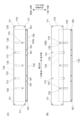
- FIG. 1 is a schematic diagram showing a shutter device according to a first embodiment.
- 4A and 4B are diagrams illustrating an open state of the shutter door in the shutter device of the first embodiment.
- FIG. 2 is a partially enlarged view showing the protective member of the first embodiment.
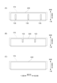
- FIG. 2 is a development view illustrating the configuration of the protective member according to the first embodiment.
- 5A to 5C are diagrams illustrating the operation of the protective member according to the first embodiment.
- 5A to 5C are diagrams illustrating the operation of the protective member according to the first embodiment.
- FIG. 4 is a flow diagram of a method for attaching the protective member according to the first embodiment.
- 13A and 13B are explanatory diagrams of a slide member according to a modified example.
- FIG. 11 is a schematic diagram showing a shutter device according to a second embodiment.
- FIG. 11 is an overall perspective view of a protective member according to a second embodiment.
- FIG. 11 is a front view of a protective member according to a second embodiment.
- 13A and 13B are explanatory diagrams of a protective member according to a second embodiment.
- FIG. 11 is a flow diagram of a method for attaching a protective member according to a second embodiment.
- 13A to 13C are diagrams illustrating the operation of the protective member according to the second embodiment.
- 13A and 13B are explanatory diagrams of a protective member according to a modified example.
- a shutter device 1 used for opening and closing an opening formed in a front wall of a refrigerated warehouse will be described as an example of an object to be installed. It should be noted that the embodiments described below are preferred specific examples of the present disclosure and therefore have various technical limitations. However, the scope of the present disclosure is not limited to these embodiments unless otherwise specified in the following description.
- FIG. 1 is a schematic diagram showing a shutter device according to the first embodiment.
- FIG. 2 is a diagram showing an open state of the shutter door in the shutter device of the first embodiment.
- a shutter device 1 of this embodiment includes a shutter door 10 , a guide body 30 , and a protective member 100 .
- the shutter device 1 of this embodiment is set at an opening of a building that requires heat insulation performance, such as a refrigerated warehouse or a freezer warehouse.
- the shutter device 1 of this embodiment has a panel 11 (described later) constituting the shutter door 10 with a thickness of about 50 mm to 80 mm for heat insulation and condensation prevention. Therefore, when opening and closing the shutter door 10, a gap GP (see FIG.
- the shutter door 10 has a plurality of panels 11 connected in the moving direction, and can be bent at the connection parts where the panels 11 are adjacent to each other.
- the shutter door 10 is configured such that the plurality of panels 11 are connected to each other, and can move along the guide body 30.
- These multiple panels 11 are connected to each other via connectors such as hinges (not shown) so that they can bend.
- the shutter door 10 can bend along the guide path of the guide 30 by the adjacent panels 11 rotating relative to each other around an axis extending in the width direction in the movement direction (the direction of arrows D1 and D2) when opening and closing.
- the number and size of the panels 11 are not particularly limited, and can be set appropriately depending on the degree of deformation required when being guided by the guide body 30. Furthermore, the material constituting the panel 11 is not particularly limited as long as it has a strength sufficient to prevent damage at least when the opening and closing operation of the opening is performed. Examples of the material constituting the panel 11 include metal materials such as aluminum, steel, and stainless steel, and synthetic resin materials such as polycarbonate, polyester, and polyvinyl chloride.
- the shutter door 10 only needs to be guided along the path of the guide body 30 and be movable between the open position and the closed position, and there is no particular limitation on its shape or configuration.
- the shutter door 10 is formed by connecting a plurality of panels 11 each having a horizontally elongated rectangular shape extending in the width direction along the movement direction.
- the shutter door 10 of this embodiment has multiple panels 11 that extend long in the width direction (one direction) lined up in a cross direction that intersects with the width direction.
- one panel 11 and another panel 11 adjacent to each other in the cross direction are connected via a connection part.
- the multiple panels 11 are lined up in the vertical direction, and one panel 11A is provided below the other panel 11B (see Figure 3 described later).
- the shutter door 10 is movable between a closed position in which the opening of the refrigerated warehouse is closed, as shown in FIG. 1, and an open position in which the opening of the refrigerated warehouse is opened, as shown in FIG.
- the shutter door 10 is provided with a handle 15 on the outer surface of the panel 11. The user can manually move the shutter door 10 between an open position and a closed position by operating the handle 15.
- the shutter door 10 is also provided with a window 17 for checking the internal situation.
- the shutter door 10 also has a weight (not shown) connected to the rear end 18 via a wire.
- the wire is a long member that transmits the tensile force due to the weight of the weight to the shutter door 10, with one end connected to the rear end 18 of the shutter door 10 and the other end connected to the weight. In other words, the wire extends so as to hang down on the side opposite the front end 16 of the shutter door 10.
- the wire transmits the force of the weight pulling the shutter door 10 toward the rear end 18, and the shutter door 10 moves while being guided by the guide body 30 while the weight of the shutter door 10 and the weight of the weight are appropriately balanced, thereby opening and closing the opening of the refrigerated warehouse. Therefore, when the shutter door 10 moves to open, the force of the weight pulling the shutter door 10 toward the rear end 18 prevents the shutter door 10 from contracting in the direction of movement, thereby suppressing noise caused by the shutter door 10 contracting.
- the shutter door 10 is also connected to a shaft 551 via a gear (not shown).
- a spring is connected to this shaft 551, which assists the user in opening the shutter door 10. In other words, when the shutter door 10 is closed, the spring is wound and spring force is accumulated. On the other hand, when the shutter door 10 is opened, the spring is unwound and the released spring force becomes a driving force that assists the user in opening the door.
- the front end 16 and the rear end 18 of the shutter door 10 are expressions based on the movement direction when the shutter door 10 is opened and closed.
- the end that is the leading edge when the shutter door 10 is moved to close is called the front end 16
- the end that is the leading edge when the shutter door 10 is moved to open is called the rear end 18. Therefore, the shutter door 10 has a front end 16 on the open position side in the movement direction, and a rear end 18 on the closed position side in the movement direction.
- the guide body 30 guides the shutter door 10 moving along the moving direction, and guides the shutter door 10 composed of a plurality of panels 11 from a linear movement to a movement along a curved track and then to a linear movement again.
- These guide bodies 30 are arranged in pairs on one side and the other side in the width direction at the opening and ceiling of the refrigerated warehouse in which they are to be installed. Specifically, as shown in FIG. 1, the guide body 30 is configured with a front guide section 31 arranged in the opening-side straight track area, an upper guide section 33 arranged in the ceiling-side straight track area, and a curved guide section 32 arranged in the bent track area.
- the front guide portion 31 is a portion that guides the shutter door 10 in the vertical direction at the opening of the refrigerated warehouse.
- the upper guide portion 33 is a portion that guides the shutter door 10 in the front-to-rear direction on the ceiling of the refrigerated warehouse.
- the curved guide portion 32 is a portion that guides movement between the front guide portion 31 and the upper guide portion 33 along a curved (arcuate) trajectory.
- a cover portion 50 is provided on the ceiling side of the refrigerated warehouse to be installed, which closes the space between the ceiling of the refrigerated warehouse and the upper guide portion 33 of the guide body 30, and a shaft 551 is arranged within this cover portion 50.
- the cover portion 50 is also provided with a sealing member 553 that seals the gap between the cover portion 50 and the shutter door 10.
- This sealing member 553 is desirably made of a flexible rubber material that can deform appropriately according to the surface shape of the shutter door 10 to ensure airtightness.
- the material that constitutes the guide 30 is not particularly limited as long as it has at least a strength that is not easily deformed when the shutter door 10 comes into contact with it.
- metal materials such as aluminum, steel, and stainless steel, and synthetic resin materials such as polyethylene, fluororesin, and polyamide resin can be used for the guide 30.
- the upper guide section 33 may generate loud sliding noises because the shutter door 10 slides under the load of its own weight.
- the upper guide section 33 is preferably made of, for example, polyethylene, which has low sliding resistance, and preferably high-density polyethylene. This makes it possible to suppress the sliding noises of the shutter door 10.
- the shutter door 10 guided by the above-mentioned guide body 30 is in the closed position as shown in FIG. 1, and when the opening of the refrigerated warehouse is opened, it is guided by the front guide portion 31 to move upward in the vertical direction, and is guided by the curved guide portion 32 to move along an arc-shaped trajectory and change direction to the rear in the front-to-rear direction. It then continues to be guided by the upper guide portion 33 to move backward in the front-to-rear direction, and moves to the open position shown in FIG. 2.
- the shutter door 10 when the shutter door 10 is in the open position as shown in FIG. 2 and the opening of the refrigerated warehouse is to be closed, it is guided by the upper guide portion 33 to move forward in the front-to-rear direction, and is guided by the curved guide portion 32 to move along a curved track and change direction downward in the up-down direction. It then continues to move downward in the up-down direction while being guided by the front guide portion 31, and moves to the closed position shown in FIG. 1.
- the guide body 30 has at least a partially curved path, and guides the movement of the shutter door 10 as the shutter door 10 bends.
- FIG. 3 is a partially enlarged view showing the protective member 100 of the first embodiment.
- FIG. 4 is a development view illustrating the configuration of the protection member 100 according to the first embodiment.
- FIG. 5 is a diagram illustrating the operation of the protection member 100 according to the first embodiment.
- FIG. 6 is a diagram illustrating the operation of the protection member 100 according to the first embodiment.
- the protective member 100 is provided across a certain panel 11 (hereinafter referred to as "first panel 11A") and a panel 11 adjacent to the certain panel (hereinafter referred to as “other panel 11B").
- the protective member 100 covers the space between the first panel 11A and the other panel 11B with a deformable sliding member 130.
- the protective member 100 has a sliding member 130 attached to one panel 11A, and a cover member 170 attached to the other panel 11B so as to cover the sliding member 130.
- the slide member 130 is a plate-like member that can be bent and deformed, with one end 132 in a cross direction that crosses the width direction attached to one panel 11A, and the other end 134 in the cross direction covering at least a portion of the other panel 11B.
- the sliding member 130 is composed of a deformable sliding plate 131 having a horizontally elongated rectangular shape with a thickness of, for example, 6 mm.
- One end 132 of the sliding member 130 is held by an adjacent panel 11A, and the other end 134 can cover at least a portion of the other adjacent panel 11B.
- one end 132 of the sliding plate 131 of the sliding member 130 is held by the one panel 11A, and the other end 134 is not attached to the other panel 11B and covers at least a portion of it. Therefore, the other end 134 of the sliding plate 131 of the sliding member 130 is a movable free end.
- one end 132 of the slide plate 131 of the slide member 130 is held near the upper end of the one panel 11A located below.
- the slide member 130 follows the one panel 11A located below when the adjacent one panel 11A and the other panel 11B bend and move.
- the first panel 11A located below does not change direction immediately.
- the sliding member 130 is exposed from the inside of the cover member 170 facing the opening side, covering and concealing the space between the adjacent first panel 11A and the other panel 11B.
- the sliding plate 131 also has a number of through holes 139 through which a fixing member for mounting to one panel 11A can be inserted, and in this embodiment, only one end 132 of the sliding plate 131 is attached to one panel 11A via a retaining member 150.
- the sliding plate 131 has a plurality of through holes 139 at one end 132 thereof through which a fixing member for attaching it to one panel 11A is inserted.
- the rigid, elongated fixing plate 151 constituting the holding member 150 also has a plurality of through holes 159 at positions corresponding to the through holes 139 of the sliding plate 131.
- the fixing plate 151 is a rod-shaped member that extends along the width direction, which corresponds to the longitudinal direction of the sliding member 130.
- the fixing plate 151 is placed on the sliding plate 131 so as to be aligned with the first end 132 side, and then a fixing member such as fixing member 161 is used to attach only the first end 132 side of the sliding plate 131 together with the fixing plate 151 to the first panel 11A.
- a fixing member such as fixing member 161 is used to attach only the first end 132 side of the sliding plate 131 together with the fixing plate 151 to the first panel 11A.
- the sliding member 130 can be attached to the outer surface of the first panel 11A.
- the fixing member 161 in this embodiment can be a drill screw, which is a screw with a drill-shaped tip.
- the fixing member 161 is not inserted through the panel 11, but the fixing plate 151 and the sliding plate 131 are fixed to the panel 11. This prevents any parts from being installed on the side of the panel 11 opposite the side where the protective member 100 is attached (the rear side).
- the slide member 130 via the holding member 150, the one end 132 side of the slide plate 131 that will be attached to one panel 11A can be held uniformly with the same pressure.
- the slide plate 131 is further provided with an opening for avoiding the spacer 110 provided in the overlapping region between the slide member 130 and the cover member 170. As shown in FIG. 4, this opening can have a different shape depending on the position where the spacer 110 is provided.
- the slide plate 131 is provided with a narrow concave notch 133 and a narrow strip-shaped notch 135 as openings that are formed to extend long along the intersecting direction.
- the opening can be a narrow concave notch 133 that opens along the movement direction of the panel 11 at the other end 134 of the slide plate 131.
- the opening can be a narrow strip-shaped notch 135 along the movement direction of the panel 11.
- the narrow strip-shaped notch 135 has a first end 135a provided on one side in the intersecting direction and a second end 135b provided on the other side in the intersecting direction. Then, when the slide member 130 moves back and forth relative to the cover member 170, the spacer 110 (spacer 115 for narrow strip-shaped notch) is movable between the first end 135a and the second end 135b.
- the spacer 110 can be provided in the overlapping area between the slide member 130 and the cover member 170 without interfering with the movement (movement in and out) of the slide member 130 in the storage area 175 provided inside the cover member 170. Furthermore, by appropriately changing the shape of the opening depending on the position where the spacer 110 is provided, the movement of the slide member 130 can be made efficient and effective.
- the slide member 130 can move as a whole along the movement direction of the panel 11 without colliding with the spacer 110 from the start to the end of the movement.
- This narrow strip-shaped notch 135 is formed so as to avoid the narrow strip-shaped notch spacer 115 described below.
- the other end 134 side of the slide member 130 can be moved along the movement direction of the panel 11 without the slide member 130 colliding with the spacer 110 just before the movement ends.
- This narrow concave notch 133 is formed so as to avoid the concave notch spacer 113 described below.
- this slide plate 131 is not particularly limited as long as it is heat-insulating, can be deformed to bend, and the other end 134 side can be movably inserted into the accommodation area 175 of the cover member 170, but for example, urethane foam is desirable.
- This urethane foam is lightweight, heat-insulating, and flexible enough to bend as the panel 11 bends, and has low surface friction resistance, making it easy to move within the accommodation area 175 and unlikely to wear out due to movement.
- a foamed polyethylene sheet or a foamed polypropylene sheet may be used for the slide plate 131.
- Various colors such as white, light blue, blue, and black may be used for the color of the slide plate 131. It is preferable that the color of the slide plate 131 is the same as or similar to the color of the surface of the panel 11.
- the cover member 170 is a plate-like member attached to the other panel 11B, and forms a space in which the slide member 130 is provided so as to be movable forward and backward, and in which the other end 134 of the slide member 130 is disposed.
- the cover member 170 forms an accommodation area 175 on the inside into which the other end 134 of the slide member 130 is movably inserted.
- the cover member 170 is then attached to the other panel 11B via a spacer 110 that forms the accommodation area 175.
- the cover member 170 is a member that covers the slide member 130, and forms a storage area 175 in which the other end 134 of the slide member 130 is movable (see FIG. 6).
- This cover member 170 can be composed of a strong cover plate 171 that is, for example, a horizontally elongated rectangle with a thickness of 6 mm and a width slightly larger than that of the slide member 130.
- the cover plate 171 is also provided with a plurality of through holes 179 through which fixing members for mounting to another panel 11B are inserted, and at least the four corners of the cover plate 171 are mounted to the other panel 11B.
- the cover plate 171 has a through hole 179 at each of the four corners, and also has a plurality of through holes 179 in the overlapping area between the slide member 130 and the cover member 170 for inserting a fixing member for attaching the spacer 110.
- the spacer 110 is a cylindrical body through which an internal fixing member can be inserted.
- the spacer 110 is configured with a fixing pin spacer 111, a concave notch spacer 113, and a narrow band notch spacer 115, depending on the installation position.
- the concave notch spacer 113 and the narrow band notch spacer 115 are provided at opposing positions to the opening in the slide member 130 when the cover member 170 and the slide member 130 are stacked, and protrude from the plate surface of the cover member 170 by a distance greater than the thickness of the slide member 130.
- the spacer 110 forms a storage area 175 that creates a space in which the end of the slide member 130 is placed (see FIG. 6).
- the concave notch spacer 113 and the narrow band notch spacer 115 are provided on the movement path of the slide member 130 that moves back and forth relative to the cover member 170.
- spacers 111 for the fixing pins, 113 for the concave notches, and 115 for the narrow strip notches each have different uses, and their thickness and materials can be changed as appropriate depending on the installation location, so for ease of explanation, they will be described with different names.
- the fixing pin spacer 111 is for inserting the fixing members 112 for attaching the four corners of the cover plate 171 to the other panel 11B while forming a predetermined gap in the overlapping area between the slide member 130 and the cover member 170.
- the cover member 170 can be attached while forming a storage area 175 on the outer surface of the other panel 11B.
- the concave cutout spacer 113 is a space through which the concave cutout fixing member 114 is inserted to attach the temporary overlapping area of the slide member 130 and the cover member 170 to another panel 11B while forming a predetermined gap in the overlapping area between the slide member 130 and the cover member 170.
- the cover member 170 can be attached while forming the storage area 175 in the overlapping area between the slide member 130 and the cover member 170.
- the narrow strip-shaped notch spacer 115 is a space through which the narrow strip-shaped notch fixing member 116 is inserted to attach the area where the slide member 130 and the cover member 170 always overlap, while forming a predetermined gap in the overlapping area between the slide member 130 and the cover member 170, to another panel 11B.
- the cover member 170 can be attached while forming the storage area 175 in the overlapping area between the slide member 130 and the cover member 170.
- the fixing member 112, the fixing member for the concave notch 114, and the fixing member for the narrow band notch 116 can be drill screws with drill-shaped tips.
- the cover plate 171 is fixed to the panel 11 without these fixing members penetrating the panel 11. This prevents any parts from being installed on the side of the panel 11 opposite the side where the protective member 100 is attached (the rear side).
- spacers 110 spacer 111 for the fixing pin, spacer 113 for the concave notch, and spacer 115 for the narrow strip notch
- the narrow strip-shaped notch spacer 115 when the slide member 130 is accommodated inside the cover member 170, the narrow strip-shaped notch spacer 115 is accommodated within the narrow strip-shaped notch 135 from start to finish of movement, guiding the slide plate 131. Therefore, the slide member 130 can stably guide the entire slide plate 131 along the movement direction of the shutter door 10 without tilting obliquely with respect to the movement direction of the shutter door 10.
- the concave notch spacer 113 guides the slide plate 131 so that it is accommodated in the narrow concave notch 133 just before the movement ends. Therefore, the slide member 130 can reliably guide the other end 134 of the slide plate 131 along the movement direction of the shutter door 10 without tilting obliquely relative to the movement direction of the shutter door 10.
- each of the spacers 110 (fixing pin spacer 111, concave notch spacer 113, narrow band notch spacer 115) can be, for example, 10 mm.
- a storage area 175 with a height of 10 mm is formed between the cover member 170 and the other panel 11B, and the other end 134 of the slide member 130, which has a thickness of 6 mm, can be movably inserted into the storage area 175 formed inside the cover member 170 without any hindrance.
- this cover plate 171 is not particularly limited as long as it has thermal insulation properties and is strong enough to form the storage area 175 inside, and can be, for example, a composite plate called aluminum sandwich, in which an insulating material is sandwiched between aluminum.
- This aluminum sandwich is made up of multiple layers, with a core material (insulating layer) made of insulating material sandwiched between thin aluminum plates, and is lightweight, strong, and can be cut with a cutter.
- the protective member 100 configured as described above accommodates most of the slide member 130, including the other end 134 of the slide plate 131, within the accommodation area 175 formed inside the cover member 170.
- the slide member 130 is exposed as if it is being pulled out from the inside of the cover member 170, following the bending of the shutter door 10.
- one end 132 of the slide member 130 is pulled out from the inside (storage area 175) of the cover member 170, while the other end 134 is not exposed from the storage area 175 and is deformed so as to bend toward the other panel 11B as it is pressed down by the cover member 170, thereby covering at least a portion of the other panel 11B. Therefore, the gap GP that occurs at the connection of the panels 11 is covered and physically protected by the sliding member 130, thereby preventing a person from unconsciously inserting his or her fingertips between adjacent panels 11A and 11B.
- the cover member 170 presses down on the slide member 130, so the protective member 100 does not get in the way when opening and closing the door.
- one end 132 (lower side) of the slide member 130 is fixed by the holding member 150 to one panel 11 that is arranged lower than the other panels 11B when the multiple panels that make up the panel section are lined up in the vertical direction.
- the slide member 130 is in a fixed state with the end portion that is upstream in the traveling direction when the shutter door 10 is lowered downward (arrow D2). Therefore, the slide member 130, which is configured to be able to be curved and deformed, is less likely to be damaged as the shutter door 10 moves to open and close.
- the protective member 100 is attached to one location between one panel 11A and another panel 11B, but the present invention is not limited to this.
- the protective member 100 may be provided at multiple locations so as to cover the space between adjacent panels 11.
- the vertical positional relationship of the protection member 100 may be reversed from that in this embodiment. That is, the cover member 170 may be provided on one panel 11A side, and the slide member 130 may be provided on the other panel 11B side.
- the protective member 100 is provided on the panel 11 to which the handle 15 is attached (see FIG. 3).
- the shutter door 10 is opened and closed using the handle 15.
- some users may move the shutter door 10 by placing their hand in the gap GP between the panels 11 near where the handle 15 is provided, without using the handle 15.
- the protective member 100 of this embodiment is attached to the panel 11 to which the handle 15 is provided, making it particularly unlikely for the protective member 100 to be caught in the gap between the panels 11.
- the protective member 100 of this embodiment may also be installed on the rear side of the shutter door 10. That is, the protective member 100 is attached to the gap GP that occurs on the rear side of the panel 11 that constitutes the shutter door 10. This makes it possible to prevent a user from being pinched in the gap GP between the panels 11 when opening and closing the shutter door 10 inside a room such as a freezer where the shutter device 1 opens and closes.
- a single protective member 100 is provided across the entire width of the shutter door 10 in the width direction, but this is not limited to this form.
- a single gap GP formed between one panel 11A and another panel 11B may be covered by arranging multiple (e.g., two) protective members 100 in the width direction.
- the above-mentioned embodiment describes a shutter device 1 equipped with a guide body 30 that includes an area that guides the shutter door 10 to move along an arc-shaped trajectory between the opening side and the ceiling side of the installation target, but the present invention is not limited to this form. Therefore, the shutter device may be provided with a guide body 30 including an area for guiding the shutter door 10 to move along a circular arc between the opening side and the side wall side of the installation target. In other words, the shutter device may be a shutter device in which the shutter door 10 opens sideways in the horizontal direction.
- FIG. 7 is a flow diagram of a method for attaching the protective member 100 according to the first embodiment.
- a fixing step is performed to fix the sliding member 130, which is formed in a plate shape extending long in one direction, has openings (narrow concave notch 133, narrow strip-shaped notch 135) formed along a cross direction intersecting the one direction, and is capable of bending and deforming, to the shutter door 10 (S901).
- the fixing plate 151 of the holding member 150 is placed on one end 132 side of the sliding member 130, and is fixed to one panel 11A (panel 11) using a fixing member 161.
- a layering step is performed in which the cover member 170, which is formed in a plate shape extending long in one direction, is layered on the slide member 130 (S902). Then, an insertion process is performed in which the spacers 110 (spacer 111 for fixing pin, spacer 113 for concave notch, spacer 115 for narrow strip-shaped notch) protruding from the cover member 170 are inserted into the openings (narrow concave notch 133, narrow strip-shaped notch 135) of the slide member 130 (S903).
- an attachment process is performed in which the cover member 170 is attached to the shutter door 10 via the spacer 110 (S904). Specifically, the cover member 170 is fixed to the other panel 11B (panel 11) using the fixing member 112, the fixing member 114 for the concave notch, and the fixing member 116 for the narrow band-shaped notch.
- the protective member 100 which is provided across one panel 11A and another panel 11B and covers the space between the one panel 11A and the other panel 11B using a deformable sliding member 130, can be attached to the shutter door 10.
- FIG. 8 is an explanatory diagram of a modified slide member.
- the sliding member 130 is described as being provided with both the narrow concave notch 133 and the narrow strip-shaped notch 135 in the sliding plate 131, but is not limited to this.
- a slide member 230 may be formed by providing only a narrow band-shaped notch 135 on a slide plate 131 .
- a slide member 330 may be formed by providing only a narrow concave cutout 133 on a slide plate 131 .
- a slide member 430 may be provided in which the slide plate 131 does not have either the narrow concave notch 133 or the narrow strip-shaped notch 135. That is, no opening is formed in the modified slide member 430. Therefore, for example, the strength of the modified slide member 430 can be further increased.
- FIG. 9 is an explanatory diagram of a modified protective member 200. As shown in FIG.
- the modified protective member 200 has a deformable member 930 that is configured to be deformable, a holding member 950 that holds the deformable member 930 to the panel 11, and a fixing bolt 970 that fixes the holding member 950.
- the deformable member 930 is a plate-like member that extends long in the width direction (one direction).
- the deformable member 930 may be made of an elastic material such as synthetic rubber.
- the holding member 950 is a rod-shaped member that extends long in the width direction (one direction). In this example, the holding member 950 is formed in a rectangular shape.
- the holding member 950 is provided corresponding to each of the first panel 11A and the second panel 11B.
- the fixing bolt 970 fixes the retaining member 950 to the panel 11 with the deformable member 930 sandwiched between the panel 11 and the retaining member 950 .
- a modified protective member 200 covers the space between one panel 11A and another panel 11B using a deformable member 930 that is configured to be deformable.
- the deformable member 930 covers the space between the one panel 11A and the other panel 11B.
- the modified protective member 200 prevents a fingertip from being unconsciously inserted between the adjacent one panel 11A and the other panel 11B.
- FIG. 10 is a schematic diagram showing a shutter device 2 according to the second embodiment.
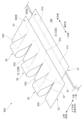
- FIG. 11 is an overall perspective view of a protective member 500 according to the second embodiment.
- the shutter device 2 of the second embodiment includes a shutter door 10, a guide body 30, and a protective member 500. That is, the shutter device 2 of the second embodiment differs from the shutter device 1 of the first embodiment in the configuration of the protective member 500.
- the protective member 500 of the second embodiment will be described in detail below.
- the shutter device 2 of this embodiment includes multiple (e.g., three) protective members 500.
- the multiple protective members 500 are arranged in a line along the width direction. That is, in the shutter device 2 of this embodiment, multiple protective members 500 are arranged in a line along the width direction for one shutter door 10. In the shutter device 2 of this embodiment, the multiple protective members 500 are arranged in a line along the width direction, so that the gap GP (see FIG. 11 described later) between one panel 11A and another panel 11B is covered by the multiple protective members 500.
- the width of the individual protective member 500 is configured to be smaller than the width of the panel 11.
- the width of the panel varies depending on the type of shutter device. Therefore, in this embodiment, the width of the protective member 500 is configured to be relatively small. And, by using a number of protective members 500 according to the size of the panel of the shutter device to be installed, it is possible to accommodate multiple types of shutter devices of different sizes.
- the protective member 500 has a first structural portion 51 attached to one panel 11A, a second structural portion 53 attached to another panel 11B, and a bent portion 55 connecting the first structural portion 51 and the second structural portion 53.
- the protective member 500 is made of a single, relatively thin, flexible plate-like member, as described below.
- the first structural portion 51, the second structural portion 53, and the bent portion 55 are not formed by connecting separately constructed members, but are formed as a single unit. That is, the first structural portion 51, the second structural portion 53, and the bent portion 55 are formed as a single unit.
- the first structural part 51 is rectangular and elongated in the width direction, and is formed in a plate shape.
- the first structural part 51 covers the gap GP between the first panel 11A and the other panel 11B.
- the first structural part 51 has a cover part 511 that covers the gap GP, and a connection part 512 that forms a connection point with the panel 11 (the first panel 11A).
- the covering portion 511 is formed to extend elongatedly in the width direction and has a predetermined length in the intersecting direction.
- the length of the covering portion 511 in the intersecting direction is formed to be longer than the maximum width of the gap GP formed between one panel 11A and the other panel 11B.
- connection portion 512 forms the portion where the first structural part 51 is attached to the panel 11.
- the connection portion 512 is provided at one end of the first structural part 51 in the intersecting direction.
- a fixing member 59 (described later) is provided to pass through the connection portion 512.
- the second structural part 53 has a comb-like shape.
- the second structural part 53 has a clamping part 531 that clamps the first structural part 51, and a connecting part 532 that forms a connection point with the panel 11 (another panel 11B).
- the clamping portion 531 is rectangular in the width direction and formed in a plate shape.
- the clamping portion 531 is located forward of the first structural portion 51 in the front-rear direction.
- the clamping portion 531 clamps the first structural portion 51 between itself and the panel 11 (the other panel 11B).
- the clamping portion 531 is a plate-shaped member in which the first structural portion 51 is provided so as to be movable forward and backward, and forms a space in which the other end side of the first structural portion 51 is disposed.
- the clamping portion 531 in this embodiment is provided on the front side of the cover portion 511 of the first structural portion 51 in a state in which the protective member 500 is attached to the shutter door 10.
- the pressing portion 531 acts to press the cover portion 511 of the first structural portion 51 toward the panel 11 when, for example, the shutter door 10 is opened or closed.
- connection portion 532 is provided above the clamping portion 531 in the cross direction.
- the connection portions 532 are provided at multiple locations. Bending portions 55 are provided between adjacent connection portions 532.
- the connection portions 532 form the locations where the second structural portion 53 is attached to the panel 11.
- a fixing member 59 which will be described later, is provided to pass through the connection portions 532.
- the bent portion 55 is formed in a rectangular shape that is long in the transverse direction.
- the bent portion 55 is bent to form a loop when attached to the panel 11.
- the bent portion 55 is connected to the first structural portion 51 at one end and to the second structural portion 53 at the other end.
- the bent portion 55 has a slit portion 57, which is a notch, between the second structural portion 53 in the width direction. In other words, the bent portion 55 is separated from the second structural portion 53 in the width direction.
- multiple bent portions 55 e.g., three) are provided for each first structural portion 51 and each second structural portion 53.
- the bending portion 55 is deformable due to its flexible material and loop-shaped structure. In this embodiment, the bending portion 55 is deformed by increasing or decreasing the diameter of the loop.
- the bending portion 55 is formed integrally with the covering portion 511 and the clamping portion 531, allowing the covering portion 511 to move in the intersecting direction relative to the clamping portion 531.
- connection portion 532 between one bent portion 55 and another adjacent bent portion 55.
- the connection portions 532 are formed in multiple locations.
- the protective member 500 can be stably fixed to the panel 11 by the multiple connection portions 532.
- the protective member 500 of this embodiment is provided across one panel 11A and the other panel 11B.
- the protective member 500 has a covering portion 511 that covers the space between the one panel 11A and the other panel 11B, and a clamping portion 531 that is formed integrally with the covering portion 511 and clamps the covering portion 511 between the panel 11.
- the protective member 500 is able to accommodate the gap GP between the one panel 11A and the other panel 11B that changes as the panel is opened and closed, as the bending portion 55 and the covering portion 511 deform.
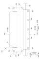
- FIG. 12 is a front view of the protective member 500 of the second embodiment.
- the protective member 500 is fixed to the panel 11 using fixing members 59 (a first fixing member 591 and a second fixing member 592 described later).
- fixing members 59 a first fixing member 591 and a second fixing member 592 described later.
- a drill screw having a drill-shaped tip can be used as the fixing member 59.
- the first structural part 51 is attached to one panel 11A by being fixed at the connection part 512.
- a plurality of (e.g., five) first fixing members 591 are used to attach the first structural part 51.
- the plurality of first fixing members 591 are arranged at predetermined intervals in the width direction. In this way, the end part of the first structural part 51 on one end side in the transverse direction (the lower end part in the up-down direction) is fixed to one panel 11A.
- the second structural part 53 is attached to the other panel 11B by being fixed to the connection parts 532.
- a total of multiple (e.g., eight) second fixing members 592 are used to attach the second structural part 53.
- the second structural part 53 in this embodiment has connection parts 532 provided at multiple locations (four locations in this example). Then, multiple (e.g., two) second fixing members 592 are used at each connection part 532.
- the multiple second fixing members 592 are arranged at predetermined intervals in the intersecting direction.
- the second fixing member 592 is provided at the outer end in the width direction of the connection part 532.
- the second fixing member 592 is provided at the center in the width direction of the connection part 532.
- the connection part 532 is fixed between the other panel 11B and the other panel 11B via a washer (not shown).
- the thickness of the washer can be, for example, greater than or equal to the thickness of the first structural part 51 (covering part 511).
- the second structural part 53 forms a space between the other panel 11B and the second structural part 53 in which the covering part 511 provided on the other end side of the first structural part 51 is arranged, and the covering part 511 of the first structural part 51 can be moved forward and backward in the space.
- the second structural portion 53 is fixed mainly at the other end side in the intersecting direction (the upper end side in the up-down direction) to the other panel 11B.
- the bending portion 55 is not directly fixed to the panel 11. Therefore, the bending portion 55 is capable of deformation and movement.
- FIG. 13 is an explanatory diagram of a protective member 500 according to the second embodiment.
- a method for producing the protective member 500 of this embodiment will be described.
- a flexible plate-like member formed in a thin, flat shape can be used for the protective member 500.
- Engineering plastics such as polyvinyl chloride resin can be used as the material for the protective member 500.
- the thickness of the protective member 500 is preferably 0.2 mm or more and 5 mm or less, and more preferably 0.5 mm or more and 2 mm or less.
- portions having shapes corresponding to the first structural portion 51, the second structural portion 53, and the bent portion 55 are formed in the plate-like material.
- Each of the components can be formed, for example, by punching the rectangular plate-like material or by cutting the rectangular plate-like material using a laser, a cutter, or the like.
- the first structural portion 51 and the second structural portion 53 are connected by a bent portion 55 extending long in the intersecting direction.
- a slit portion 57 is provided between one connection portion 532 and the other connection portion 532 in the second structural portion 53.
- the plate-shaped material is provided with a first surface 500A, which is, for example, the front side, and a second surface 500B, which is, for example, the back side.
- the length L22 in the width direction of the second structural portion 53 is set to be longer than the length L21 in the width direction of the first structural portion 51. This allows the first structural portion 51 to be contained inside the second structural portion 53 in the width direction when the first structural portion 51 and the second structural portion 53 are overlapped. In other words, the covering portion 511 of the first structural portion 51 is entirely covered by the sandwiching portion 531 of the second structural portion 53 (see FIG. 11 ). Further, the length L32 of the second structural portion 53 in the intersecting direction is set to be longer than the length L31 of the first structural portion 51 in the intersecting direction.
- the protective member 500 configured as described above is a single plate-like member that is flexible. By bending the protective member 500 at the bending portion 55, the second structural portion 53 is disposed above the first structural portion 51, and the first structural portion 51 and the second structural portion 53 can be overlapped.
- FIG. 14 is a flow diagram of a method for attaching the protective member 500 of the second embodiment.
- a preparation step is performed to prepare a plate-shaped member of the protection member 500 on which the first structural portion 51, the second structural portion 53 and the bent portion 55 are respectively formed (S1401).
- a first fixing step is performed to fix the first structural part 51 to the panel 11 (S1402).
- the protective member 500 is installed so that the second surface 500B faces the panel 11 and the first surface 500A faces the outside of the panel 11.
- the connection part 512 of the first structural part 51 is fixed to one panel 11A using a first fixing member 591.
- the first structural part 51 is attached to the panel 11 from the first surface 500A side using the first fixing member 591.
- a folding step is performed (S1403) to fold the protective member 500.
- the protective member 500 is folded back at the bent portion 55 so that the first surface 500A of the first structural portion 51 and the first surface 500A of the second structural portion 53 face each other.
- a second fixing step is performed to fix the second structural part 53 to the panel 11 (S1404).
- the clamping part 531 of the second structural part 53 covers the first structural part 51, and the connection part 532 of the second structural part 53 is fixed to the other panel 11B using the first fixing member 591.
- the second structural part 53 is attached to the panel 11 from the second surface 500B side using the second fixing member 592.
- the protective member 500 that spans one panel 11A and another panel 11B and covers the space between the one panel 11A and the other panel 11B can be attached to the shutter door 10.
- FIG. 15 is an explanatory diagram of the operation of the protection member 500 according to the second embodiment.
- the bending part 55 provided between the first structural part 51 and the second structural part 53 deforms so that the diameter of the loop becomes smaller, so that the first structural part 51 is pulled out to the first panel 11A side.
- the gap GP occurring at the connection part of the panel 11 is covered and hidden by the protective member 500 and is physically protected. Therefore, insertion of fingertips between adjacent panels 11A and 11B is prevented.
- the first structural part 51 is in a state in which the cover part 511 is pulled out from the second structural part 53. At this time, one end side of the first structural part 51 in the intersecting direction is fixed to one panel 11A by the connection part 512, and the other end side is pressed against the shutter door 10 side by the clamping part 531 of the second structural part 53. This prevents the first structural part 51 from, for example, bulging or getting caught on other members.
- the protective member 500 of this embodiment is installed so that the bent portion 55 is convex on the upper side in the vertical direction, but is not limited to this form.
- the protective member 500 may be attached so that the bent portion 55 is located on the lower side in the vertical direction.
- the bent portion 55 so that it is convex on the upper side in the vertical direction, even if foreign matter such as dust or moisture due to humidity adheres to the protective member 500, the foreign matter or moisture is less likely to accumulate on the bent portion 55.
- FIG. 16 is an explanatory diagram of a modified protective member 500. As shown in FIG.
- the protective member 500 has a first structural portion 51 attached to one panel 11A, a second structural portion 53 attached to another panel 11B, and a bent portion 255 connecting the first structural portion 51 and the second structural portion 53.
- the protective member 500 of the modified example is configured with a single bent portion 255 instead of a plurality of bent portions 255. That is, one bent portion 255 is connected to one first structural portion 51 and one second structural portion 53.
- the protective member 500 of the modified example configured in this manner can also cover the gap GP between one panel 11A and the other panel 11B that occurs as the shutter door 10 moves.
- the bent portion 55 has a relatively wide width. Therefore, the durability of the bent portion 55 can be improved.
- a cover that covers the bent portions 55 from the outside may be provided.
- the cover that covers the bent portions 55 is of a size that can cover all of the multiple bent portions 55, and for example, a rectangular, plate-shaped structure can be used.
- the cover that covers the bent portions 55 is fixed to the other panel 11B on which the bent portions 55 are provided.
- the cover that covers the bent portions 55 may be integrated with a structural portion that constitutes the protective member 500, such as the second structural portion 53, or may be provided separately from the structural portion that constitutes the protective member 500. By providing such a cover, the cover can press down the bent portions 55 to prevent the bent portions 55 from protruding outward.
- shutter device 1 and shutter device 2 are examples of shutter devices.
- Shutter door 10 is an example of a panel portion.
- Handle 15 is an example of an operating portion.
- Guide body 30 is an example of a guide portion.
- Protective member 100 and protective member 500 are examples of a cover portion or cover body.
- Spacer 110 is an example of a spacer or protruding member.
- Slide member 130 is an example of a first structure.
- Holding member 150 is an example of a holding member or rod member.
- Cover member 170 is an example of a first structure.
- Narrow concave notch 133 and narrow strip-shaped notch 135 are examples of openings.
Landscapes
- Engineering & Computer Science (AREA)
- Structural Engineering (AREA)
- Architecture (AREA)
- Civil Engineering (AREA)
- Mechanical Engineering (AREA)
- Specific Sealing Or Ventilating Devices For Doors And Windows (AREA)
Priority Applications (1)
| Application Number | Priority Date | Filing Date | Title |
|---|---|---|---|
| JP2025532831A JPWO2025013941A1 (https=) | 2023-07-13 | 2024-07-12 |
Applications Claiming Priority (2)
| Application Number | Priority Date | Filing Date | Title |
|---|---|---|---|
| JP2023-115276 | 2023-07-13 | ||
| JP2023115276 | 2023-07-13 |
Publications (1)
| Publication Number | Publication Date |
|---|---|
| WO2025013941A1 true WO2025013941A1 (ja) | 2025-01-16 |
Family
ID=94215921
Family Applications (1)
| Application Number | Title | Priority Date | Filing Date |
|---|---|---|---|
| PCT/JP2024/025387 Pending WO2025013941A1 (ja) | 2023-07-13 | 2024-07-12 | シャッタ装置、カバー体およびカバー体の取付方法 |
Country Status (2)
| Country | Link |
|---|---|
| JP (1) | JPWO2025013941A1 (https=) |
| WO (1) | WO2025013941A1 (https=) |
Citations (8)
| Publication number | Priority date | Publication date | Assignee | Title |
|---|---|---|---|---|
| JPS6323472U (https=) * | 1986-07-30 | 1988-02-16 | ||
| JPH01142188A (ja) * | 1987-08-11 | 1989-06-05 | Hoermann Kg Brockhagen | 組み合わせドア板 |
| JPH0260197U (https=) * | 1988-10-26 | 1990-05-02 | ||
| JPH07324555A (ja) * | 1994-05-30 | 1995-12-12 | Sanwa Shutter Corp | ドア体の指詰め防止カバー |
| CN2692322Y (zh) * | 2004-03-02 | 2005-04-13 | 三和卷帘门工业株式会社 | 平板式卷帘门装置 |
| JP2005264553A (ja) * | 2004-03-18 | 2005-09-29 | Sanwa Shutter Corp | 建築用開閉装置 |
| JP2008121367A (ja) * | 2006-11-15 | 2008-05-29 | Novoferm Gmbh | くぐり戸を備えるセクション型ゲートのゲート扉 |
| JP2021105269A (ja) * | 2019-12-26 | 2021-07-26 | 株式会社豊田自動織機 | 車両用開閉装置 |
-
2024
- 2024-07-12 JP JP2025532831A patent/JPWO2025013941A1/ja active Pending
- 2024-07-12 WO PCT/JP2024/025387 patent/WO2025013941A1/ja active Pending
Patent Citations (8)
| Publication number | Priority date | Publication date | Assignee | Title |
|---|---|---|---|---|
| JPS6323472U (https=) * | 1986-07-30 | 1988-02-16 | ||
| JPH01142188A (ja) * | 1987-08-11 | 1989-06-05 | Hoermann Kg Brockhagen | 組み合わせドア板 |
| JPH0260197U (https=) * | 1988-10-26 | 1990-05-02 | ||
| JPH07324555A (ja) * | 1994-05-30 | 1995-12-12 | Sanwa Shutter Corp | ドア体の指詰め防止カバー |
| CN2692322Y (zh) * | 2004-03-02 | 2005-04-13 | 三和卷帘门工业株式会社 | 平板式卷帘门装置 |
| JP2005264553A (ja) * | 2004-03-18 | 2005-09-29 | Sanwa Shutter Corp | 建築用開閉装置 |
| JP2008121367A (ja) * | 2006-11-15 | 2008-05-29 | Novoferm Gmbh | くぐり戸を備えるセクション型ゲートのゲート扉 |
| JP2021105269A (ja) * | 2019-12-26 | 2021-07-26 | 株式会社豊田自動織機 | 車両用開閉装置 |
Also Published As
| Publication number | Publication date |
|---|---|
| JPWO2025013941A1 (https=) | 2025-01-16 |
Similar Documents
| Publication | Publication Date | Title |
|---|---|---|
| US20040244919A1 (en) | Sliding screen door | |
| JPH0819813B2 (ja) | 組み合わせドア板 | |
| WO2025013941A1 (ja) | シャッタ装置、カバー体およびカバー体の取付方法 | |
| US4344205A (en) | Cable bushing | |
| EP1873336B1 (en) | A locking assembly for a ventilating window | |
| JP2016098603A (ja) | シャッター用ガイドレールの構造 | |
| WO2020129340A1 (ja) | 指挟み防止装置 | |
| JP3942071B2 (ja) | ドア装置 | |
| JPH0665067U (ja) | シートのスライド機構 | |
| US20030068970A1 (en) | Hingeless ventilator | |
| JP3940061B2 (ja) | 開閉装置の密閉構造 | |
| JP3924934B2 (ja) | フラットケーブル | |
| EP3275708B1 (en) | Open roof construction for a vehicle and rollo assembly for use therein | |
| EP1650393A1 (en) | Door with protection element | |
| GB2291092A (en) | Finger guards for doors | |
| JP2550331Y2 (ja) | シヤツター用のスラツト保持装置 | |
| JP5007150B2 (ja) | プラットホームドア装置 | |
| JP5007149B2 (ja) | プラットホームドア装置 | |
| JP2020190119A (ja) | 指挟み防止装置 | |
| JP3830426B2 (ja) | チルトシャッター装置 | |
| JP3088338U (ja) | 可動式遮光プレートスクリーン | |
| JP3944060B2 (ja) | 開閉装置における座板部材の収納構造 | |
| JP3606379B2 (ja) | 引戸用制動装置 | |
| JP2008279942A (ja) | プラットホームドア装置 | |
| EP2767665A1 (en) | Closure arrangement |
Legal Events
| Date | Code | Title | Description |
|---|---|---|---|
| 121 | Ep: the epo has been informed by wipo that ep was designated in this application |
Ref document number: 24839829 Country of ref document: EP Kind code of ref document: A1 |
|
| ENP | Entry into the national phase |
Ref document number: 2025532831 Country of ref document: JP Kind code of ref document: A |
|
| WWE | Wipo information: entry into national phase |
Ref document number: 2025532831 Country of ref document: JP |
|
| NENP | Non-entry into the national phase |
Ref country code: DE |