WO2025013418A1 - 圧入装置 - Google Patents
圧入装置 Download PDFInfo
- Publication number
- WO2025013418A1 WO2025013418A1 PCT/JP2024/018418 JP2024018418W WO2025013418A1 WO 2025013418 A1 WO2025013418 A1 WO 2025013418A1 JP 2024018418 W JP2024018418 W JP 2024018418W WO 2025013418 A1 WO2025013418 A1 WO 2025013418A1
- Authority
- WO
- WIPO (PCT)
- Prior art keywords
- press
- jig
- fitting
- axis
- cylinder
- Prior art date
- Legal status (The legal status is an assumption and is not a legal conclusion. Google has not performed a legal analysis and makes no representation as to the accuracy of the status listed.)
- Pending
Links
Images


Classifications
-
- B—PERFORMING OPERATIONS; TRANSPORTING
- B23—MACHINE TOOLS; METAL-WORKING NOT OTHERWISE PROVIDED FOR
- B23P—METAL-WORKING NOT OTHERWISE PROVIDED FOR; COMBINED OPERATIONS; UNIVERSAL MACHINE TOOLS
- B23P19/00—Machines for simply fitting together or separating metal parts or objects, or metal and non-metal parts, whether or not involving some deformation; Tools or devices therefor so far as not provided for in other classes
- B23P19/02—Machines for simply fitting together or separating metal parts or objects, or metal and non-metal parts, whether or not involving some deformation; Tools or devices therefor so far as not provided for in other classes for connecting objects by press fit or for detaching same
Definitions
- the present invention relates to a press-fitting device.
- a press-fitting device is used to press-fit a press-fitting part into a part to be pressed in.
- One such press-fitting device has a lower press-fitting jig arranged at the bottom of a C-shaped column, an upper press-fitting jig arranged at the top of the C-shaped column facing the lower press-fitting jig, and a servo press that displaces the upper press-fitting jig toward the lower press-fitting jig.
- Patent Document 1 discloses a press machine having a similar configuration to this type of press-fitting device.
- the gear part is supported by a lower press-in jig, and the bearing is supported by an upper press-in jig.
- the upper press-in jig is displaced toward the lower press-in jig by a servo press mechanism, and the bearing supported by the upper press-in jig is inserted onto the shaft portion of the gear part supported by the lower press-in jig, and the shaft portion is pressed into the bearing.
- the press-fitting jigs need to be replaced every time the type of press-fitting part they support is changed.
- the press-fitting device In order to replace the press-fitting jig, the press-fitting device must be stopped and the replacement must be performed manually by an operator. If the frequency of replacing the press-fitting jig increases, this may result in an increase in work costs and a decrease in production efficiency. Therefore, there is a demand to minimize the impact on operating costs and production efficiency even if the frequency of replacing press-fitting jigs increases.
- One aspect of the present invention is a jig unit including a pair of press-fitting jigs disposed opposite to each other on a first axis line and a guide rail that supports one of the pair of press-fitting jigs movably in the first axial direction; a table on which the jig unit is mounted and which is rotatable about a rotation axis parallel to the first axis; a press mechanism that moves a cylinder disposed on a second axis parallel to the rotation shaft back and forth along the second axis, a plurality of the jig units are mounted on the table at intervals in a circumferential direction around the rotation axis, When viewed from the rotation axis direction, the first axis of each of the jig units is located on a virtual circle centered on the rotation axis,
- the one press-fitting jig was a press-fitting device having a connecting portion that was connected to the cylinder.
- FIG. 1 is a diagram illustrating a press-fitting device.
- FIG. 2 is a diagram illustrating the press-fitting device.
- FIG. 3 is a diagram illustrating a press-fitting device.
- FIG. 4 is a diagram illustrating a press-fitting jig.
- FIG. 5 is a diagram illustrating a press-fitting jig.
- FIG. 6 is a diagram illustrating a locking arm provided on the slider.
- FIG. 7 is a diagram illustrating the lock mechanism.
- FIG. 8 is a diagram illustrating the lock mechanism.
- FIG. 9 is a diagram illustrating the lock mechanism.
- FIG. 10 is a diagram for explaining an example of use of the press-fitting device.
- FIG. 1 is a diagram for explaining the press-fitting device 1, and is a perspective view of the press-fitting device 1 seen from diagonally above.
- FIG. 2 is a diagram for explaining the press-fitting device 1, and is a side view of the press-fitting device 1 seen from the side.
- FIG. 3 is a diagram for explaining the press-fitting device 1, and is a plan view of the press-fitting device 1 seen from above.
- the column 8 supporting the cylinder 7 is shown by a virtual line
- the movement locus of the axis X2 of the column 8 when the table 6 is rotated around the rotation axis C is shown by a virtual circle Im1.
- the area where the press-fitting jig 22 is located is shown by a dashed line.
- the press-fitting device 1 has a table 6 on which the jig unit 2 is mounted, a cylinder 7, and a column 8 that supports the cylinder 7.
- the column 8 is a frame that supports the cylinder 7 movably in the direction of the axis X2.
- the column 8 has a support base 81 placed on the installation surface GD, a vertical frame portion 82 extending upward from the support base 81 in the direction of the vertical line VL, a lower frame portion 83 extending laterally from a lower portion of the vertical frame portion 82 toward the table 6 side, and an upper frame portion 84 extending laterally from an upper portion of the vertical frame portion 82 toward the table 6 side.
- the lower frame portion 83 and the upper frame portion 84 extend in the same direction, and the column 8 is generally C-shaped in side view.
- the lower frame portion 83 and the upper frame portion 84 are spaced apart in the direction of a vertical line VL based on the installation state of the press-fitting device 1.
- the cylinder 7 is supported by the upper frame portion 84 so as to be movable back and forth along an axis X2.
- the axis X2 is a straight line that is perpendicular to the installation surface GD and extends along the vertical line VL.
- a servo press mechanism 75 (press mechanism) is attached to the top of the upper frame portion 84. The servo press mechanism 75 causes the cylinder 7 to advance and retreat in the direction of the axis X2 (up and down in FIG. 2).
- a space is provided between the upper frame portion 84 and the lower frame portion 83 in the direction of the vertical line VL so that the jig unit 2 mounted on the table 6 can pass through.
- the table 6 is rotatably supported via bearings (not shown) on a base 61 installed on the installation surface GD.
- the table 6 has a substantially circular outer diameter when viewed from above (see FIG. 3).
- the table 6 rotates around a rotation axis C, which is the central axis of the table 6, by a drive mechanism (not shown) installed inside the base 61.
- the upper surface 6a of the table 6 is a flat surface perpendicular to the rotation axis C.
- the upper surface 6a is a flat surface that is aligned along the horizontal line HL and perpendicular to the axis X2 described above and an axis X1 described later.
- the jig unit 2 has a lower press-fitting jig 21 and an upper press-fitting jig 22.
- the press-fitting jig 21 and the press-fitting jig 22 are disposed opposite to each other on a common axis X1.
- the press-fitting jig 22 is supported by the guide rail 23 via a slider 24.
- the slider 24 is capable of moving in the vertical direction along the guide rail 23.
- the press-fitting jig 22 supported by the slider 24 is also capable of moving in the vertical direction along the guide rail 23.
- a plurality of jig units 2 are mounted on the table 6 at predetermined intervals in the circumferential direction about the rotation axis C.
- Each jig unit 2 is provided in a direction along a diameter line L of the table 6 with the guide rail 23 facing the rotation axis C.
- four jig units 2 are mounted on the table 6.
- the jig units 2 are provided in the circumferential direction around the rotation axis C at 90 degree intervals.
- the column 8 is provided in a direction along the diameter line L of the table 6 with the cylinder 7 facing the rotation axis C side.
- the arrangement of each jig unit 2 and the relative positional relationship between the table 6 and the column 8 are determined so that the axis X2 of the cylinder 7 and the axis X1 of each jig unit 2 are located on a common imaginary circle Im1.
- the jig unit 2 mounted on the table 6 passes between the lower frame portion 83 (see Figure 2) and the upper frame portion 84 (see Figure 2) of the column 8 in sequence.
- the jig unit 2 is positioned at a position where the axis X1 of the jig unit 2 coincides with the axis X2 of the cylinder 7, and then the cylinder 7 is moved downward toward the table 6, thereby displacing the upper press-fitting jig 22 in a direction approaching the lower press-fitting jig 21.
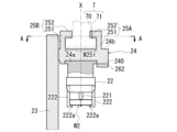
- FIG. 6 is a diagram for explaining the engagement arms 25A, 25B provided on the slider 24.
- Fig. 6 shows the engagement arms 25A, 25B and a cross section of the guide rail 23 taken along line AA in Fig. 4, as well as the cylinder 7 in imaginary lines.
- the press-fitting jig 21 is fixed to a support base 210 installed on the table 6.
- the press-fitting jig 21 has a center pin 211 to be inserted into the workpiece W1.
- the press-fitting jig 21 is installed with the center pin 211 facing upward.
- the center pin 211 is located on the axis X1 and extends linearly upward.
- a peripheral portion 21a surrounding the center pin 211 serves as a mounting surface for the workpiece W1 that is extrapolated onto the center pin 211.
- the center pin 211 is inserted into an axial hole (not shown) of the workpiece W1, and the workpiece W1 is arranged in a direction along the axis X1.
- the axis W1a to be press-fitted into the workpiece W2 is arranged facing upward on the axis X1.
- the press-fitting jig 22 is attached to a recess 24a that opens on the lower surface of the slider 24.
- the press-fitting jig 22 has a center pin 221 to be inserted into the workpiece W2.
- the press-fitting jig 22 is installed with the center pin 221 facing downward.
- the center pin 221 is located on the axis X1 and extends linearly downward.
- the press-fitting jig 22 is provided with support arms 222 surrounding the center pin 221. Three support arms 222 are provided at intervals in the circumferential direction around the axis X1 (see Fig. 1).
- the workpiece W2 inserted around the center pin 221 is supported by the press-fitting jig 22 as the claw portion 222a provided at the tip of the support arm 222 engages with the lower surface.
- the press-fitting jig 22 is displaced toward the lower press-fitting jig 21, the shaft portion W1a of the workpiece W1 supported by the press-fitting jig 21 is press-fit into the workpiece W2.
- the slider 24 supporting the press-fitting jig 22 has a pair of engagement arms 25A, 25B provided on an upper surface 24b of a plate-shaped base 240.
- the engagement arms 25A, 25B extend along the axis X1 in a direction away from the press-fitting jig 22.
- the pair of engagement arms 25A, 25B are coupling portions with the cylinder 7.
- the engagement arms 25A, 25B have wall portions 251, 251 and locking portions 252, 252.
- the wall portions 251, 251 are plate-shaped portions extending linearly upward from the upper surface 24b of the base portion 240. As shown in Fig. 6, the wall portions 251, 251 have a width W240 in the circumferential direction around the rotation axis C that matches with the base portion 240.
- the walls 251, 251 face each other at a distance W251 in the radial direction of the rotation axis C of the table 6.
- the distance W251 between the walls 251, 251 is set to be larger than the outer diameter R71 of the flange portion 71 (W251>R71) so that the flange portion 71 of the cylinder 7 can be inserted therein.
- the locking portions 252, 252 protrude from the opposing surfaces of the wall portions 251, 251 in a direction approaching each other (a direction approaching the axis X1).
- the tip surfaces 252a, 252b of the locking portions 252, 252 are arc-shaped along the imaginary circles Im2, Im3, respectively.
- the tip surfaces 252a, 252b face each other with a gap W252 in the radial direction of the rotation axis C.
- the gap W252 between the tip surfaces 252a, 252b is set to be larger than the outer diameter R70 of the shaft portion 70 (W252>R70) so that the shaft portion 70 of the cylinder 7 can be inserted.
- the gap W252 is smaller than the outer diameter R71 of the flange portion 71.
- the jig unit 2 approaches the column 8, and the axis 70 of the cylinder 7 is inserted between the pair of engagement arms 25A, 25B in the process of reaching a position where the axis X1 of the jig unit 2 is coaxial with the axis X2 of the cylinder 7 on the column 8 side.
- the flange 71 and the locking parts 252, 252 are arranged in an overlapping positional relationship when viewed from the axis X1 direction (see FIG. 6).
- the imaginary circles Im2 and Im3 are imaginary circles centered on the rotation axis C of the table 6.
- the imaginary circle Im2 has a larger diameter than the imaginary circle Im1 centered on the rotation axis C.
- the imaginary circle Im3 has a smaller diameter than the imaginary circle Im1 centered on the rotation axis C.
- the imaginary circle Im1 corresponds to the movement trajectory that the axis X2 of the cylinder 7 describes on the table 6 when the table 6 rotates around the rotation axis C.
- the base 240 of the slider 24 is oriented along the diameter line L of the table 6.
- the region of the base 240 closer to the rotation axis C (left side in FIG. 6 ) than the engaging arm 25B serves as an engaging portion 241 with the guide rail 23.
- the engaging portion 241 is provided with a notch 242 through which the guide portion 232 and the connecting portion 233 on the guide rail 23 side can be inserted.
- the lower end of the guide rail 23 is fixed to the upper surface 6a of the table 6 (see FIG. 5).
- the guide rail 23 has a plate-shaped base 231 parallel to an end 241a on the inner diameter side of the slider 24 (base 240).
- the base 231 and the guide portion 232 are provided parallel to each other with a gap therebetween in the radial direction of the rotation axis C.
- the base 231 is wider than the guide portion 232, and the base 231 and the guide portion 232 are connected at their central portions in the width direction (vertical direction in the figure) by a connecting portion 233.
- the engagement portion 241 on the slider 24 side engages between the guide portion 232 and the base portion 231, so that the slider 24 is able to move in the longitudinal direction (up and down direction) of the guide rail 23 while being restricted from moving in a direction away from the guide rail 23.
- FIG. 7 to 9 are diagrams illustrating the lock mechanism 9.
- FIG. 7 and 8 a main part of the lock mechanism 9 is shown in cross section. This cross section corresponds to the cross section taken along line BB in FIG.
- FIG. 7 shows a state in which the lock shaft 91 of the lock mechanism 9 is disposed at a position (restricting position) where the movement of the slider 24 (press-fitting jig 22) is restricted.
- FIG. 8 shows a state in which the lock shaft 91 of the lock mechanism 9 is disposed in a position (non-restricted position) that allows the slider 24 (press-fitting jig 22) to move.
- 9 shows a cross section of a main part of the lock mechanism 9.
- Fig. 9 corresponds to the cross section taken along line AA in Fig. 7.
- a stopper 90 is fixed to a back surface 231a of a base portion 231.
- the stopper 90 is a plate-like member that spans between the back surface 231a of the base portion 231 and one side 231b in the width direction of the base portion 231.
- the stopper 90 has a substantially L-shape.
- the stopper 90 is fixed to the guide rail 23 by a bolt (not shown).
- the stopper 90 has an extension region 901 that extends toward the engaging arm 25B side (the right side in the figure) through the side of the base 231.
- a tip 901a of the extension region 901 reaches the side of the guide portion 232.
- a cylindrical mounting portion 902 is provided on the upper surface of the extension region 901.
- the lock shaft 91 is a columnar member having a rectangular cross section. As shown in Fig. 6, the lock shaft 91 is provided on the side of the slider 24 and oriented along the diameter line L of the table 6.
- the lock shaft 91 has a length L91 that crosses the slider 24 from the side of the guide rail 23 in the radial direction of the rotation axis C (left-right direction in the figure).
- the lock shaft 91 is arranged to be movable back and forth in the direction of the diameter line L (left and right direction in FIG. 7 ) while being prevented from falling off the slider 24 by a holder member 26 attached to the slider 24 and a guide rail (not shown).
- the holder member 26 has a side plate 261 (see FIG. 6) that restricts the lateral movement of the lock shaft 91, and an under plate 262 (see FIG. 7) that supports the underside of the lock shaft 91.
- the side plate 261 is connected to the under plate 262 with bolts BL, BL.
- the under plate 262 is fixed to the underside of the slider 24 with a bolt (not shown).
- the holder member 26 is provided to hold the lock shaft 91 on the side of the slider 24 while allowing movement of the lock shaft 91 in the radial direction (the direction of the diameter line L) of the rotation axis C of the lock shaft 91 .
- the movable member 93 is an integral part having a connecting portion 932 connected to an output shaft 951 of the motor 95 and an engaging portion 931 that engages with the engaging piece 92 .
- the connecting portion 932 is a plate-like member provided in a direction perpendicular to the axis X95 of the motor 95.
- the engaging portion 931 is a plate-like member provided in a direction along the axis X95 of the motor 95.
- the engaging portion 931 extends from a lower portion of the connecting portion 932 in a direction away from the motor 95 (to the left in FIG. 7 ).
- the movable member 93 is supported by the column 8 so as to be movable back and forth in the direction of the axis X95 while the rotation of the motor 95 about the axis X95 is restricted.
- the motor 95 is fixed to a side surface of the column 8 via a bracket 94.
- the bracket 94 has a first plate 941 on which the motor 95 is placed, and a second plate 942 having an insertion hole 942a for an output shaft 951.
- An output shaft 951 of the motor 95 is rotatably supported in an insertion hole 942a of the second plate 942.
- a tip end side of the output shaft 951 is screwed into a screw hole 932a provided in the connecting portion 932 of the movable member 93.
- the movable member 93 is displaced in the direction of the axis X95 according to the rotation direction of the output shaft 951 of the motor 95.
- the output shaft 951 of the motor 95 is screwed into the connecting portion 932 of the movable member 93 to form a screw feed mechanism.
- a recess 933 that is an engaging portion with the engaging element 92 is opened on the lower surface of the engaging portion 931.
- the recess 933 has contact surfaces 933a, 933b on both sides of the engaged portion 921 in the direction of the axis X95.
- the contact surface 933b is located on the rotation axis C side (left side in the figure) as viewed from the engaged portion 921.
- the contact surface 933a is located on the opposite side of the rotation axis C as viewed from the engaged portion 921.
- the contact surfaces 933a and 933b are perpendicular to the direction of advance/retract movement of the lock shaft 91 (left/right direction in the figure: direction of axis X95).
- the recess 933 and the engaged portion 921 are arranged in a positional relationship where they overlap when viewed from the axis X1 direction (see FIG. 9). This allows the lock shaft 91 to be displaced in conjunction with the movement of the movable member 93 in the axis X95 direction.
- a corner P1 on the slider 24 side (upper side in the figure) of the contact surface 933a is located on a virtual circle Im4 centered on the rotation axis C.
- a corner P2 on the opposite side of the contact surface 933b from the slider 24 (lower side in the figure) is located on a virtual circle Im5 centered on the rotation axis C.
- the virtual circle Im5 has a larger diameter than the virtual circle Im2 described above, and the virtual circle Im4 has a larger diameter than the virtual circle Im5 (Im4>Im5>Im2).
- a distance Wx between the virtual circle Im4 and the virtual circle Im5 is larger than a diameter R921 of the engaged portion 921.
- the operation of the press-fitting device 1 will be described.
- the slider 24 approaches the cylinder 7 supported by the column 8 from the circumferential direction about the rotation axis C, as shown in FIG.
- the slider 24 supported by the guide rail 23 is disposed at a height position where the flange portion 71 can be inserted between the upper surface 24b and the locking portions 252, 252 by the stopper 90 of the guide rail 23 (see FIG. 7).
- the cylinder 7 is inserted from the circumferential direction into the space between the locking portions 252, 252 of the pair of engaging arms 25A, 25B and between the locking portions 252, 252 and the upper surface 24b of the slider 24.
- the flange portion 71 on the outer periphery of the cylinder 7 is inserted under the locking portions 252, 252 of the pair of engagement arms 25A, 25B.
- the slider 24 is suspended from the flange portion 71 of the cylinder 7.
- the slider 24 and the press-fitting jig 22 supported by the slider 24 move downward toward the press-fitting jig 21 along the guide rail 23.
- the pressing force acting on the press-fitting jig 22 from the cylinder 7 is used to press-fit the workpiece W1 supported by the press-fitting jig 21 and the workpiece W2 supported by the press-fitting jig 22 together.
- the cylinder 7 is moved upward to position the lock shaft 91 above the stopper 90 (see the upper diagram in FIG. 8).
- the motor 95 is driven to displace the movable member 93 in a direction away from the motor 95 (to the left in the drawing)
- the engaged portion 921 of the engaging element 92 is pushed by the contact surface 933a of the recess 933 and displaced toward the stopper 90 together with the lock shaft 91.
- the cylinder 7 is lowered to place the lock shaft 91 on the mounting portion 902 on the stopper 90 side. This restricts the slider 24 from moving downward.
- the cylinder 7 is slightly lowered to release the contact between the flange portion 71 and the locking portions 252, 252 of the engaging arms 25A, 25B, and then the table 6 is rotated.
- the jig unit 2 which has completed the press-fitting operation moves in a direction away from the column 8, and a new jig unit approaches the column 8.
- FIG. 10 is a diagram for explaining an example of use of the press-fitting device 1.
- four jig units 2 are mounted on the table 6.
- the jig unit 2A located directly below the column 8 performs the press-fitting operation of the workpieces W1 and W2 using the press-fitting jigs 21 and 22.
- the press-fitting is being performed by the jig unit 2A
- other operations can be performed by the other jig units 2B to 2D.
- the jig unit 2B located downstream as viewed from the column 8 can remove the workpiece set after the press-fitting is completed.
- the adjacent jig unit 2C can set the workpieces W1 and W2 in the press-fitting jig. Therefore, the pressing operation (task 1), the pressing part removal operation (task 2), and the pressing part setting operation (task 3) can be performed in parallel, which reduces the waiting time of worker M compared to a pressing device that uses a C-shaped column to support only a pair of pressing jigs. Moreover, since the above-mentioned tasks 2 and 3 are simple tasks, even if the worker M is replaced by a robot, the waiting time for the robot can be shortened. Also, only task 3 after the press-fitting task may be replaced by a robot.
- the press-fitting work can be performed continuously by attaching the same press-fitting jigs 21, 22 to each jig unit 2 (2A to 2D). This reduces waiting time, and is expected to improve the efficiency of the press-fitting work.
- press-fitting device 1 There are a wide variety of combinations of workpieces that can be pressed into using the press-fitting device 1. If there are, for example, four different combinations of workpieces to be pressed into (see FIG. 10), the press-fitting jigs 21 and 22 of each jig unit 2 (2A-2D) are set to press-fitting jigs corresponding to combinations 1 to 4, respectively, so that the press-fitting of all combinations can be performed using a single press-fitting device. This makes the press-fitting device 1 adaptable to the manufacture of a wide variety of products in small quantities.
- the press-fitting device 1 is a jig unit 2 including a pair of press-fitting jigs (a lower press-fitting jig 21 (one jig) and an upper press-fitting jig 22 (the other jig)) disposed opposite to each other on an axis X1 (a first axis), and a guide rail 23 that supports the press-fitting jig 22 so as to be movable in the direction of the axis X1; a table 6 on which the jig unit 2 is mounted and which is rotatable about a rotation axis C parallel to the axis line X1;
- the press mechanism 75 has a servo press mechanism 75 (press mechanism) that moves the cylinder 7 arranged on an axis X2 (second axis) parallel to the rotation axis C back and forth along the axis X2.
- a plurality of jig units 2 are mounted on the table 6 at intervals in the circumferential direction around the rotation axis C.
- the axis X1 of each of the jig units 2 is located on an imaginary circle Im1 centered on the rotation axis C (see FIG. 3).
- the press-fitting jig 22 has a connecting portion that is connected to the cylinder 7 .
- the operations of replacing the press-fit jigs 21 and 22, setting the workpiece in the press-fit jigs 21 and 22, and removing the workpiece from the press-fit jig 21 can be performed. These operations can be performed in parallel with the operation of pressing the workpiece in the jig unit 2 having the press-fit jig 22 engaged with the cylinder 7. This is expected to improve the work efficiency.
- the multiple jig units 2 have the same combination of workpieces W1 and W2 supported by a pair of press-fit jigs 21 and 22.
- the shaft portion W1a of the workpiece W1 supported by the press-fitting jig 21 is pressed into the workpiece W2 supported by the press-fitting jig 22, this press-fitting operation is performed by the jig unit 2 having the press-fitting jig 22 engaged with the cylinder 7.
- the other jig unit 2 is located in a position removed from the cylinder 7, and can perform the operation of setting the workpieces W1, W2 into the press-fitting jigs 21, 22 and the operation of removing the workpieces W1, W2 from the press-fitting jig 21.
- the operation of setting the workpiece on the press-fitting jig and the operation of removing the workpiece from the press-fitting jig can be performed in parallel with the operation of pressing the workpiece into the workpiece, so that the production efficiency of press-fitted parts can be improved.
- the work of setting the workpiece in the press-fitting jig and the work of removing the workpiece from the press-fitting jig are performed by a robot, these operations can be performed in parallel with the press-fitting operation.
- the robot will be in a standby state during the press-fitting operation, which reduces the operating efficiency of the robot.
- the work of setting the workpiece in the press-fitting jig and the work of removing the workpiece from the press-fitting jig can be performed in parallel with the work of pressing the workpiece into the workpiece. This shortens the waiting time of the robot and reduces the non-operating time of the robot.
- the multiple jig units 2 have different combinations of workpieces W1 and W2 supported by a pair of press-fit jigs 21 and 22.
- press-fitting operations cannot be performed not only during the operations of setting the workpieces on the press-fitting jig and removing the workpieces from the press-fitting jig, but also during the operation of replacing the press-fitting jig.
- the press-in operation can be performed in parallel with the press-in jig replacement operation, thereby preventing a decrease in production efficiency due to the replacement of the press-in jig. Furthermore, since multiple jig units 2 are mounted on the table 6, by setting different press-in jigs in advance according to the combination of workpieces corresponding to each jig unit 2, it is possible to use a press-in jig suitable for the combination of workpieces simply by rotating the table 6. Changing the press-in jig accompanying the rotation of the table 6 is less of a workload and can be completed in a shorter time than replacing the press-in jig, so it is expected that a decrease in production efficiency will be prevented.
- the press-in jig 22 can be brought closer to the cylinder 7 in the circumferential direction about the rotation axis C.
- the cylinder 7 is inserted between the locking portions 252, 252 of the pair of engaging arms 25A, 25B in the circumferential direction, and the flange portion 71 on the outer periphery of the cylinder 7 is inserted below the locking portions 252, 252 of the pair of engaging arms 25A, 25B.
- the press-fitting jig 22 is connected to the cylinder 7 with the locking portions 252, 252 of the pair of engagement arms 25A, 25B locked to the flange portion 71 on the outer periphery of the cylinder 7. Furthermore, when the table 6 is rotated, the cylinder 7 moves out from between the locking portions 252, 252 of the pair of engaging arms 25A, 25B, and the engagement between the flange portion 71 on the outer periphery of the cylinder 7 and the locking portions 252, 252 of the pair of engaging arms 25A, 25B is released. With the above-described configuration, by rotating the table 6 about the rotation axis C, the press-fitting jig 22 that engages with the cylinder 7 can be switched.
- the press-fitting jig 22 has a locking mechanism 9 that prevents the press-fitting jig 22 from moving in the direction of the axis X1 while the press-fitting jig 22 is not engaged with the cylinder 7.
- the rotation axis C is oriented along the vertical line VL.
- the press-fitting jig 22 is located above the press-fitting jig 21 in the direction of the vertical line VL.
- the lock mechanism 9 is A stopper 90 fixed to the guide rail 23; A lock shaft 91 that is attached to the press-fitting jig 22 and can move forward and backward in a direction in which the stopper 90 can be engaged with and disengaged from the stopper 90;
- the lock mechanism includes a drive unit (motor 95, output shaft 951, movable member 93) that is provided on a column 8 that supports the cylinder 7 and moves the lock shaft 91 back and forth in the engagement/disengagement direction.
- the lock shaft 91 has an engagement element 92 (engagement shaft) that extends upward along the axis X1.
- the drive unit has a movable member 93 that moves back and forth in the engagement/disengagement direction.
- the movable member 93 has a pair of contact surfaces 933a, 933b having a width in the circumferential direction around the rotation axis C.
- the pair of contact surfaces 933a, 933b are provided in the radial direction of the rotation axis C with a gap therebetween that allows the engagement piece 92 to be inserted therein.
- the engaging element 92 is inserted from the circumferential direction into the recess 933 between the pair of contact surfaces 933a, 933b during the process until the axis X1, which is the central axis of the press-fitting jig 22, reaches a position where it intersects with the axis X2, which is the central axis of the cylinder 7.
- the engaging element 92 on the lock shaft 91 side and the movable member 93 (engaging portion 931) on the drive unit side are arranged in an overlapping positional relationship when viewed from the rotation axis direction. Therefore, the lock shaft 91 can be displaced in conjunction with the displacement of the movable member 93 in the axis X95 direction by the drive unit.
- the lock shaft 91 is displaced between a position where it overlaps with the stopper 90 (restricted position) when viewed from the direction of the rotation axis C, and a position where it does not overlap with the stopper 90 (released position). Since it is only necessary to provide a drive unit in the column 8, it is possible to reduce manufacturing costs compared to the case where a drive unit is provided in each of the jig units 2.
- the pressing jig 22 can be returned to its initial position where movement can be restricted by the locking mechanism 9, and then the movement restriction by the locking mechanism 9 can be restored by operating the movable member 93 by the drive unit. This makes it possible to automate the press-fitting operation in the jig unit 2 that has reached the column 8, which is expected to improve work efficiency.
Landscapes
- Engineering & Computer Science (AREA)
- Mechanical Engineering (AREA)
- Automatic Assembly (AREA)
Priority Applications (1)
| Application Number | Priority Date | Filing Date | Title |
|---|---|---|---|
| JP2025532407A JPWO2025013418A1 (https=) | 2023-07-13 | 2024-05-18 |
Applications Claiming Priority (2)
| Application Number | Priority Date | Filing Date | Title |
|---|---|---|---|
| JP2023115040 | 2023-07-13 | ||
| JP2023-115040 | 2023-07-13 |
Publications (1)
| Publication Number | Publication Date |
|---|---|
| WO2025013418A1 true WO2025013418A1 (ja) | 2025-01-16 |
Family
ID=94215115
Family Applications (1)
| Application Number | Title | Priority Date | Filing Date |
|---|---|---|---|
| PCT/JP2024/018418 Pending WO2025013418A1 (ja) | 2023-07-13 | 2024-05-18 | 圧入装置 |
Country Status (2)
| Country | Link |
|---|---|
| JP (1) | JPWO2025013418A1 (https=) |
| WO (1) | WO2025013418A1 (https=) |
Citations (6)
| Publication number | Priority date | Publication date | Assignee | Title |
|---|---|---|---|---|
| JPS63200934A (ja) * | 1987-02-18 | 1988-08-19 | Mazda Motor Corp | 物品組立て装置 |
| JPS6416333A (en) * | 1987-07-10 | 1989-01-19 | Honda Motor Co Ltd | Press-fitting device |
| JP2016068178A (ja) * | 2014-09-29 | 2016-05-09 | 平田機工株式会社 | 圧入装置 |
| CN212762040U (zh) * | 2020-06-08 | 2021-03-23 | 信阳同裕电子科技有限公司 | 一种pin针压装设备 |
| CN112935793A (zh) * | 2021-01-29 | 2021-06-11 | 浙江博民机电股份有限公司 | 一种球阀自动装配机 |
| CN113319783A (zh) * | 2021-06-21 | 2021-08-31 | 深圳汇智文化科技有限公司 | 一种vr听筒智能制造设备 |
Family Cites Families (2)
| Publication number | Priority date | Publication date | Assignee | Title |
|---|---|---|---|---|
| JPS6074968U (ja) * | 1983-10-28 | 1985-05-25 | トヨタ自動車株式会社 | 多種オイルシ−ル圧入機 |
| JP2001001219A (ja) * | 1999-06-16 | 2001-01-09 | Hiroshima Aluminum Industry Co Ltd | 自動工具交換装置及び部品組付装置 |
-
2024
- 2024-05-18 JP JP2025532407A patent/JPWO2025013418A1/ja active Pending
- 2024-05-18 WO PCT/JP2024/018418 patent/WO2025013418A1/ja active Pending
Patent Citations (6)
| Publication number | Priority date | Publication date | Assignee | Title |
|---|---|---|---|---|
| JPS63200934A (ja) * | 1987-02-18 | 1988-08-19 | Mazda Motor Corp | 物品組立て装置 |
| JPS6416333A (en) * | 1987-07-10 | 1989-01-19 | Honda Motor Co Ltd | Press-fitting device |
| JP2016068178A (ja) * | 2014-09-29 | 2016-05-09 | 平田機工株式会社 | 圧入装置 |
| CN212762040U (zh) * | 2020-06-08 | 2021-03-23 | 信阳同裕电子科技有限公司 | 一种pin针压装设备 |
| CN112935793A (zh) * | 2021-01-29 | 2021-06-11 | 浙江博民机电股份有限公司 | 一种球阀自动装配机 |
| CN113319783A (zh) * | 2021-06-21 | 2021-08-31 | 深圳汇智文化科技有限公司 | 一种vr听筒智能制造设备 |
Also Published As
| Publication number | Publication date |
|---|---|
| JPWO2025013418A1 (https=) | 2025-01-16 |
Similar Documents
| Publication | Publication Date | Title |
|---|---|---|
| JP4367666B2 (ja) | ねじ締付装置 | |
| KR101845955B1 (ko) | 차량용 3차원 파이프 원주용접용 수직형 용접장치 | |
| CN110181282B (zh) | 一种集钻铣送钉于一体的复合铆接辅助设备 | |
| CN114393307B (zh) | 一种两侧夹持型焊接工装 | |
| KR101812694B1 (ko) | 크랭크 샤프트의 단면을 가공하기 위한 기계 및 방법 | |
| KR20120074000A (ko) | 회전형 용접장치 | |
| RU2685921C2 (ru) | Центрирующее приспособление для носителя конструктивного элемента и способ центрирования и фиксации центрирующей оправки | |
| CN212288814U (zh) | 锁盖双工位旋铆机 | |
| WO2025013418A1 (ja) | 圧入装置 | |
| US10792777B2 (en) | Indexer for operating workpieces | |
| KR101419055B1 (ko) | 공작기계의 자동 공구교환장치 | |
| KR20130032032A (ko) | 자동차 조향장치용 인풋 샤프트 가공장치 | |
| KR20180056435A (ko) | 회전형 지그장치 | |
| CN108907440B (zh) | 一种用于冲焊蹄铁面板上焊接套管和加强销的组合夹具 | |
| CN213672316U (zh) | 工装切换系统 | |
| CN121624831B (zh) | 一种减震器前叉支架的卧式装配设备 | |
| KR20230079658A (ko) | 너트 런너 소켓 교환 장치 | |
| KR102461865B1 (ko) | 터렛 공구대 장치 | |
| CN222643732U (zh) | 一种机器人自动换套筒装置 | |
| CN223971250U (zh) | 一种夹持工装及钻孔攻牙机 | |
| CN117226366B (zh) | 一种海洋港口机械高端装备焊接机器人 | |
| CN223382916U (zh) | 一种变位机的移动翻转结构 | |
| CN222971385U (zh) | 一种可快速更换工装的变位机机构 | |
| KR101200314B1 (ko) | 자동 공구교환장치 | |
| CN220993529U (zh) | 一种机床中心托架 |
Legal Events
| Date | Code | Title | Description |
|---|---|---|---|
| 121 | Ep: the epo has been informed by wipo that ep was designated in this application |
Ref document number: 24839315 Country of ref document: EP Kind code of ref document: A1 |
|
| ENP | Entry into the national phase |
Ref document number: 2025532407 Country of ref document: JP Kind code of ref document: A |
|
| WWE | Wipo information: entry into national phase |
Ref document number: 2025532407 Country of ref document: JP |
|
| NENP | Non-entry into the national phase |
Ref country code: DE |