WO2025013272A1 - 車両制御システム - Google Patents
車両制御システム Download PDFInfo
- Publication number
- WO2025013272A1 WO2025013272A1 PCT/JP2023/025835 JP2023025835W WO2025013272A1 WO 2025013272 A1 WO2025013272 A1 WO 2025013272A1 JP 2023025835 W JP2023025835 W JP 2023025835W WO 2025013272 A1 WO2025013272 A1 WO 2025013272A1
- Authority
- WO
- WIPO (PCT)
- Prior art keywords
- attack
- cyber
- vehicle control
- vehicle
- control system
- Prior art date
- Legal status (The legal status is an assumption and is not a legal conclusion. Google has not performed a legal analysis and makes no representation as to the accuracy of the status listed.)
- Pending
Links
Images


Classifications
-
- G—PHYSICS
- G06—COMPUTING OR CALCULATING; COUNTING
- G06F—ELECTRIC DIGITAL DATA PROCESSING
- G06F21/00—Security arrangements for protecting computers, components thereof, programs or data against unauthorised activity
- G06F21/50—Monitoring users, programs or devices to maintain the integrity of platforms, e.g. of processors, firmware or operating systems
- G06F21/55—Detecting local intrusion or implementing counter-measures
Definitions
- Patent Document 1 describes an unauthorized intrusion prevention device in which an on-board device transmits logs collected in the vehicle to a central device outside the vehicle, the central device determines whether a temporary measure is necessary, and if it determines that a temporary measure is necessary, transmits an instruction to execute the temporary measure to the on-board device.
- Patent Document 1 has the problem that, because it waits for instructions from a central device installed outside the vehicle before taking action against a cyber-attack, there is a long time lag between receiving a cyber-attack and taking action.
- the present invention aims to provide a vehicle control system that can shorten the time it takes to respond to a cyber attack.
- a vehicle control system is a vehicle control system equipped with a plurality of control devices and mounted on a vehicle, where at least one of the plurality of control devices is equipped with a calculation device, and the calculation device detects a cyber-attack on the plurality of control devices, implements a first countermeasure against the cyber-attack to prevent or mitigate the impact of the cyber-attack or other cyber-attacks subsequent to the cyber-attack, transmits attack information regarding the cyber-attack to a center device provided outside the vehicle, receives countermeasure information corresponding to the attack information from the center device after implementing the first countermeasure, and implements a second countermeasure different from the first countermeasure based on the countermeasure information.
- the present invention makes it possible to shorten the time it takes to respond to a cyber attack.
- FIG. 1 is a block diagram illustrating a hardware configuration of a vehicle control system according to the first embodiment.
- FIG. 2 is a block diagram illustrating a functional configuration of the vehicle control system according to the first embodiment.
- FIG. 3 is a flowchart of the process executed by the vehicle control system.
- FIG. 4 is an explanatory diagram of the secondary countermeasure carried out by the vehicle control device.
- FIG. 5 is a flowchart of a process executed by the vehicle control system according to the second embodiment.
- FIG. 6 is a block diagram showing a schematic functional configuration of a vehicle control system according to the third embodiment.
- FIG. 7 is a block diagram showing a schematic functional configuration of a vehicle control system according to the fourth embodiment.
- FIG. 8 is an explanatory diagram of a method for changing the software location.
- FIG. 9 is an explanatory diagram of a procedure for changing the ID of each ECU.
- FIG. 10 is an explanatory diagram of a measure for executing degenerate software.
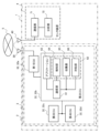
- FIG. 1 is a block diagram showing a schematic hardware configuration of a vehicle control system 1 according to the first embodiment.
- the vehicle control system 1 includes a vehicle control device 3 mounted on a vehicle 2, and a center device 4 provided outside the vehicle 2. Note that the vehicle control system 1 may have multiple vehicles 2 and vehicle control devices 3.
- FIG. 1 shows only one set of a vehicle 2 and a vehicle control device 3.
- the vehicle control device 3 is equipped with an antenna 30 for connecting to the wireless communication network 5.
- the center device 4 is equipped with an antenna 40 for connecting to the wireless communication network 5.
- the vehicle control device 3 and the center device 4 are configured to be able to communicate data with each other via the wireless communication network 5.
- the wireless communication network 5 is, for example, a mobile phone network including multiple base stations or a satellite communication network including multiple communication satellites.
- the vehicle control device 3 is a control device that controls each part of the vehicle 2.
- the vehicle control device 3 is equipped with multiple ECUs.
- a first ECU 32a, a second ECU 32b, a third ECU 32c, and a fourth ECU 32d are shown as examples of multiple ECUs equipped in the vehicle control device 3. In the following description, these ECUs are collectively referred to as ECU 32.
- the first ECU 32a is connected to the antenna 30 and the second ECU 32b.
- the second ECU 32b, the third ECU 32c, and the fourth ECU 32d are connected to each other.
- the connection form of the multiple ECUs 32 described here is one example.
- the connection form between the ECUs 32 is determined appropriately depending on the number of ECUs 32, their purpose, etc.
- the first ECU 32a is composed of a computer having an arithmetic device 51 such as a CPU (Central Processing Unit), MPU (Micro Processing Unit), DSP (Digital Signal Processor), etc., a non-volatile memory 52 such as a ROM (Read Only Memory), flash memory, hard disk drive, etc., a volatile memory 53 known as RAM (Random Access Memory), an input/output interface 54, and other peripheral circuits. These hardware components work together to operate software and realize multiple functions.
- the first ECU 32a may be composed of one computer or multiple computers.
- the arithmetic device 51 may be an ASIC (application specific integrated circuit), FPGA (Field Programmable Gate Array), etc.
- the non-volatile memory 52 stores programs capable of executing various calculations.
- the non-volatile memory 52 is a storage medium (storage device) capable of reading programs that realize the functions of this embodiment.
- the volatile memory 53 is a storage medium (storage device) that temporarily stores the results of calculations by the calculation device 51 and signals input from the input/output interface 54.
- the calculation device 51 is a device that expands the programs stored in the non-volatile memory 52 into the volatile memory 53 and executes calculations, and performs predetermined calculation processing on data taken from the input/output interface 54, the non-volatile memory 52, and the volatile memory 53 in accordance with the programs.
- the input section of the input/output interface 54 converts signals input from various devices (antenna 30, second ECU 32b, etc.) into data that can be calculated by the calculation device 51.
- the output section of the input/output interface 54 generates an output signal according to the calculation result in the calculation device 51, and outputs the signal to various devices (antenna 30, second ECU 32b, etc.).
- each of the multiple ECUs 32 includes a calculation device 51, a non-volatile memory 52, a volatile memory 53, and an input/output interface 54, just like the first ECU 32a.
- the vehicle 2 has sensors, actuators, etc. (not shown). These sensors, actuators, etc. are connected to at least one of the multiple ECUs 32.
- the center device 4 is composed of a computer equipped with a calculation device 41 such as a CPU, MPU, DSP, etc., a non-volatile memory 42 such as a ROM, flash memory, hard disk drive, etc., a volatile memory 43 known as RAM, an input/output interface 44, and other peripheral circuits. These hardware components work together to operate software and realize multiple functions.
- the center device 4 may be composed of one computer or multiple computers. Also, an ASIC, FPGA, etc. can be used as the calculation device 41.
- the non-volatile memory 42 stores programs capable of executing various calculations.
- the non-volatile memory 42 is a storage medium (storage device) capable of reading programs that realize the functions of this embodiment.
- the volatile memory 43 is a storage medium (storage device) that temporarily stores the results of calculations by the calculation device 41 and signals input from the input/output interface 44.
- the calculation device 41 is a device that expands the programs stored in the non-volatile memory 42 into the volatile memory 43 and executes calculations, and performs predetermined calculation processing on data taken from the input/output interface 44, the non-volatile memory 42, and the volatile memory 43 in accordance with the programs.
- the input section of the input/output interface 44 converts signals input from various devices (such as the antenna 40) into data that can be calculated by the calculation device 41.
- the output section of the input/output interface 44 generates an output signal according to the calculation result by the calculation device 41 and outputs the signal to various devices (such as the antenna 40).
- the input section of the input/output interface 44 also receives input of location information indicating the current location of each vehicle 2 and map information recording locations where the vehicle 2 can be safely stopped from the vehicle control device 3 connected to the wireless communication network 5 and devices not shown.
- the means by which the vehicle control device 3 communicates with external devices such as the center device 4 is not limited to wireless communication via the wireless communication network 5.
- wireless communication may also be used.
- the second ECU 32b includes a communication unit 61 and a security agent 62.
- a specific application 63 runs on the second ECU 32b.
- the communication unit 61 provides the application 63 and the security agent 62 with the function of performing data communication with various devices connected to the wireless communication network 5 via the first ECU 32a.
- the application 63 is a so-called application program that performs various processes, such as controlling an actuator (not shown), transmitting measured values from a sensor (not shown) to the outside via the wireless communication network 5, displaying a message on a display device (not shown), and displaying and saving data received from the outside via the wireless communication network 5.
- the security agent 62 includes a detection unit 64, a collection unit 65, and a response unit 66.
- the detection unit 64 detects cyber attacks against the vehicle control device 3.
- Cyber attacks against the vehicle control device 3 include, for example, cyber attacks against an application 63 running on one of the ECUs 32, and cyber attacks against the communication unit 61 of one of the ECUs 32.
- Cyber attacks detected by the detection unit 64 include, for example, unauthorized passing of authentication by spoofing, and denial of service attacks by sending large amounts of data.
- Cyber attacks are not limited to those caused by external communication via the wireless communication network 5.
- the detection unit 64 may be configured to detect cyber attacks even when the cyber attacks are directly directed at sensors or actuators (not shown), or when the cyber attacks are caused by unauthorized devices attached to the transmission paths between devices.
- the detection unit 64 outputs attack information related to the detected cyber-attack to the collection unit 65 and the response unit 66.
- the detection unit 64 transmits the attack information to the center device 4.
- the attack information is information indicating that a cyber-attack has occurred.
- the attack information includes information about the cyber-attack itself, such as an ID that identifies the ECU 32 that was the target of the attack, the type of cyber-attack (spoofing, denial of service, etc.), and characteristics according to the type of cyber-attack (authentication information of the target of spoofing in the case of spoofing, and frequency of data transmission in the case of a denial of service attack).
- the attack information may further include information about functions that have been (or may be) impaired by the cyber-attack, i.e., information about the damage caused by the cyber-attack.
- the collection unit 65 collects security information and vehicle control information based on the attack information output by the detection unit 64.
- the security information is information for analyzing cyber attacks, such as communication log information of the communication unit 61 and operation log information of the application 63.
- the vehicle control information is information related to the control of the vehicle 2, such as location information of the vehicle 2 and map information indicating a place where the vehicle 2 can be safely parked.
- the collection unit 65 outputs the collected security information and vehicle control information to the response unit 66.
- the collection unit 65 transmits the collected security information and vehicle control information to the center device 4.
- the response unit 66 determines and executes a response to the detected cyber attack based on the attack information output by the detection unit 64 and the security information and vehicle control information output by the collection unit 65.
- a corresponding response method for each combination of the cyber attack route and attack means is stored in advance in the non-volatile memory 52 in the form of a table, etc., and an appropriate response method is identified by searching this table.
- the response to a cyber attack executed by the response unit 66 based on the information collected in the vehicle is called a primary response.
- the primary response is carried out by the vehicle control device 3 at its own discretion, without following instructions from the center device 4. Since the center device 4 is not involved, the primary response is carried out as soon as a cyber attack is detected.
- Possible primary countermeasures include, for example, notifying the driver of vehicle 2 of the cyber-attack and urging him to switch to manual driving if vehicle 2 is in autonomous driving mode, or informing surrounding vehicles of the cyber-attack using hazard and LED displays on vehicle 2 and vehicle-to-vehicle communication, etc., to ensure safety.
- measures such as cutting off the network that has been cyber-attacked or restarting the system or ECU 32 that has been cyber-attacked may be taken.
- the communication unit 71 transmits response information indicating the content of the response determined by the analysis unit 72 to the vehicle control device 3 that transmitted the received attack information, security information, and vehicle control information, in response to the information.
- the communication unit 71 instructs the vehicle control device 3 to execute the response determined by the analysis unit 72.
- the response unit 66 of the vehicle control device 3 receives the response information transmitted from the center device 4 via the communication unit 61, it executes the response indicated by the response information.
- the response to a cyber attack that the response unit 66 executes based on instructions from the center device 4 is referred to as a secondary response. Because it is necessary to wait for instructions from the center device 4, the timing of execution of the secondary response is delayed compared to the primary response.
- wireless communication may be performed with other vehicles traveling near the cyber-attacked vehicle 2, and the other vehicles may be notified that the cyber-attacked vehicle 2 is traveling nearby via a navigation system or via infrastructure such as an electronic bulletin board.
- the logs of the cyber-attacked vehicle 2 may be analyzed, new security measures rules and software may be created, and distributed to the vehicle control device 3 (so-called OTA update).
- measures may be taken to safely stop the cyber-attacked vehicle 2 by remotely controlling the cyber-attacked vehicle 2 from the outside.
- the functional configurations of the third ECU 32c and the fourth ECU 32d are the same as those of the second ECU 32b, and therefore illustrations and explanations thereof are omitted. That is, the second ECU 32b, the third ECU 32c, and the fourth ECU 32d each have the above-mentioned security agent 62.
- the security agent 62 closest to the location where the cyber-attack was made detects the cyber-attack and takes necessary measures. For example, when a cyber-attack is made against an application 63 running on a certain ECU 32, the security agent 62 possessed by that ECU 32 detects the cyber-attack.
- the security agent 62 possessed by any of the multiple ECUs 32 may detect the cyber-attack.
- the proximity between the location where the cyber-attack was made and the security agent 62 may be determined by physical distance, communication distance, or any other arbitrary criterion.
- step S110 the detection unit 64 detects a cyber attack on the vehicle control device 3.
- step S120 the detection unit 64 transmits attack information relating to the cyber attack detected in step S110 to the center device 4.
- step S130 the detection unit 64 outputs attack information relating to the cyber attack detected in step S110 to the collection unit 65 and the response unit 66.
- step S140 the collection unit 65 collects security information and vehicle control information.
- step S150 the collection unit 65 transmits the security information and vehicle control information to the center device 4.
- step S310 the analysis unit 72 receives the attack information transmitted from the detection unit 64 of the vehicle control device 3 in step S120.
- the analysis unit 72 receives the security information and vehicle control information transmitted from the collection unit 65 of the vehicle control device 3 in step S150.
- step S330 the analysis unit 72 estimates the attack path and means of the cyber attack based on the attack information received in step S310 and the security information and vehicle control information received in step S320.
- step S340 the analysis unit 72 determines a response to the cyber attack (secondary response) according to the situation based on the attack path and means of attack estimated in step S330.
- step S350 the analysis unit 72 transmits response information indicating the secondary response determined in step S340 to the vehicle control device 3.
- FIG. 4 is an explanatory diagram of the secondary countermeasure implemented by the vehicle control device 3.
- the primary countermeasure is implemented in the cyberattacked vehicle 2a without waiting for an instruction from the center device 4, as described above.
- the center device 4 determines the content of the secondary countermeasure based on more information and instructs the cyberattacked vehicle 2a to implement the determined secondary countermeasure (transmits countermeasure information).
- the center device 4 may instruct other vehicles 2b that have not yet been cyberattacked to implement the same countermeasure as that instructed as the secondary countermeasure to the cyberattacked vehicle 2a (transmit countermeasure information).
- the calculation device 51 detects a cyber-attack against multiple ECUs 32 (control devices) and implements a primary response (first response) to prevent or mitigate the effects of that cyber-attack or any subsequent cyber-attacks. It then transmits attack information about the cyber-attack to a center device 4 provided outside the vehicle 2, and after implementing the primary response (first response), it receives response information corresponding to the attack information from the center device 4 and implements a secondary response (second response) different from the primary response (first response) based on the response information. This makes it possible to shorten the time from when a cyber-attack is received to when a response is implemented.
- Each of the multiple ECUs 32 (controllers) has a calculation device 51, and the calculation device 51 of the ECU 32 (controller) that is closest to the point of cyber-attack among the multiple ECUs 32 (controllers) implements the primary response (first response) and secondary response (second response). This makes it possible to respond quickly to a cyber-attack and prevent damage from the cyber-attack from spreading to other ECUs 32.
- the vehicle control system 1 may implement a secondary response (second response) that is different from the case where a cyber-attack is made on a single ECU 32.
- the center device 4 accumulates attack information, security information, and vehicle control information transmitted from the multiple vehicles 2, and therefore can perform better analysis than the vehicle control device 3 alone.
- the secondary response can be a process in which the center device 4 remotely controls the vehicle 2 to bring the vehicle 2 to a safe stop. This can appropriately ensure the safety of the vehicle 2.
- the vehicle control system 1 When a cyber-attack is made against an ECU 32 installed in at least one of the multiple vehicles 2, it is preferable that the vehicle control system 1 also implements a secondary response (second response) in the other ECUs 32 that are not subject to the cyber-attack. This makes it possible to implement preventive measures against cyber-attacks, improving society's overall resistance to cyber-attacks.
- FIG. 5 A vehicle control system 1 according to a second embodiment of the present invention will be described with reference to Fig. 5. Note that components that are the same as or equivalent to those described in the first embodiment are given the same reference symbols, and differences will be mainly described.
- FIG. 5 is a diagram similar to FIG. 3, and is a flowchart of the processing executed by the vehicle control system 1 according to the second embodiment.
- the processing of steps S200 to S210 is added after step S190 in the flowchart of FIG. 3.
- the processing of steps S360 to S370 is added after step S350.
- step S200 the detection unit 64 generates attack information related to the cyber-attack again and transmits it to the center device 4.
- the detection unit 64 determines from the attack information whether the cyber-attack is continuing, i.e., whether an abnormality due to the cyber-attack has still been detected in the vehicle control device 3. If the cyber-attack is continuing, i.e., if the countermeasures executed so far have not been able to fully mitigate the effects of the cyber-attack (if the cyber-attack has not been completely prevented), the process proceeds to step S130, where the primary countermeasure and secondary countermeasure appropriately selected according to the current situation are repeatedly executed. On the other hand, if the effects of the cyber-attack have been sufficiently mitigated or prevented by the countermeasures executed so far in step S200, the process shown in FIG. 5 ends.
- step S350 After sending the countermeasure information indicating the instruction for the secondary countermeasure to the vehicle control device 3 in step S350, the analysis unit 72 in step S360 receives the attack information sent from the detection unit 64 of the vehicle control device 3 in step S200. In step S370, the analysis unit 72 judges whether the cyber attack is continuing from the attack information, that is, whether an abnormality due to the cyber attack is still detected in the vehicle control device 3.
- step S320 the security information and vehicle control information are received again, and the vehicle control device 3 is caused to repeatedly execute the secondary countermeasure appropriately selected according to the current situation.
- step S370 the processing shown in FIG. 5 ends.
- the center device 4 has more time and can collect more information, making it possible to select a more appropriate countermeasure.
- a vehicle control system 100 according to a third embodiment of the present invention will be described with reference to Fig. 6. Note that components that are the same as or equivalent to those described in the first embodiment are given the same reference symbols, and differences will be mainly described.
- FIG. 6 is a block diagram similar to FIG. 1, and is a schematic diagram showing the functional configuration of a vehicle control system 100 according to a third embodiment.
- a fifth ECU 32e is added to the vehicle control device 3.
- An antenna 30a is connected to the fifth ECU 32e.
- the fifth ECU 32e is connected to the third ECU 32c. If a cyber-attack is launched on the first ECU 32a via the wireless communication network 5 and data communication via the first ECU 32a becomes impossible, a primary response is possible, but it becomes difficult to perform a secondary response to the cyber-attack in cooperation with the center device 4. For this reason, in this embodiment, the means of communication with the center device 4 is made redundant.
- the vehicle control system 100 can perform data communication with the center device 4 via the fifth ECU 32e, and can therefore reliably receive instructions for secondary measures. This makes it possible to provide a vehicle control system that is more robust against cyber-attacks.
- the data communication method between the fifth ECU 32e and the center device 4 may be different from that used by the first ECU 32a.
- the fifth ECU 32e and the center device 4 may be connected by wire.
- the ECU 32 (control device) has multiple communication paths with the center device 4. This makes it possible to provide a vehicle control system 100 that is more robust against cyber attacks.
- a vehicle control system 200 according to a fourth embodiment of the present invention will be described with reference to Figures 7 to 10. Note that components that are the same as or equivalent to those described in the first embodiment are given the same reference symbols, and differences will be mainly described.
- FIG. 7 is a block diagram similar to FIG. 2, and shows a schematic functional configuration of a vehicle control system 200 according to a fourth embodiment.
- a manager ECU 32f is added to the vehicle control device 3.
- the manager ECU 32f is connected to the other ECUs 32.
- the manager ECU 32f grasps the status of the multiple ECUs 32 and changes the settings of the multiple ECUs 32.
- the manager ECU 32f has the function of changing the software arrangement and network status of the multiple ECUs 32.
- the manager ECU 32f collects communication logs of each ECU 32 and status logs of functions provided by each ECU 32 from each ECU 32, and calculates optimal functional arrangement and communication settings.
- the master ECU 32f collects information on the security of the entire vehicle 2 and the status of each ECU 32, it is possible to take measures to ensure safety while continuing to collect information on cyber attacks. For example, if the second ECU 32b is subjected to a cyber attack, the application 63 running on the second ECU 32b may be moved to another ECU 32, and safety actions may be taken such as safely stopping the vehicle 2, while the cyber attack on the second ECU 32b may continue and information on the cyber attack may continue to be collected.
- FIG. 8 is an explanatory diagram of a measure to change the software arrangement.
- an application 63a necessary for safely stopping the vehicle 2 runs on the second ECU 32b
- a relatively unimportant application 63b runs on the third ECU 32c.
- the supervisory ECU 32f stops the relatively unimportant application 63b running on the third ECU 32c, and starts the application 63a running on the second ECU 32b on the third ECU 32c.
- the application 63b is stopped in order to secure the computational resources required for the operation of the application 63a.
- the application 63a may be transmitted from the second ECU 32b to the third ECU 32c, or the application 63a may be stored in advance in the non-volatile memory 52 of the third ECU 32c.
- the application 63a to be moved operates by communicating with a specific communication destination (e.g., another ECU 32, a sensor, an actuator, etc.), moving the application 63a from the second ECU 32b to the third ECU 32c may result in the application 63a being unable to communicate with the specific communication destination.
- the supervisory ECU 32f may change the settings of the communication unit 61 so that the third ECU 32c, to which the application 63a has been moved, can communicate with the specific communication destination.
- each ECU 32 When changing the software layout or communication settings between multiple ECUs 32, if each ECU 32 makes such changes individually, it becomes difficult to grasp the overall state of the vehicle control device 3. Also, each ECU 32 must be aware of its current state, which is inefficient. Therefore, the control ECU 32f aggregates information from the security agents 62 of each ECU 32 to determine which ECUs 32 have sufficient load and how much communication capacity there is between each ECU 32. In the event of a cyber attack, the control ECU 32f uses the information it has grasped to set in each ECU 32 the optimal response method across multiple ECUs 32.
- the supervisory ECU 32f may be a single ECU, or another ECU may also serve as the supervisory ECU 32f. Also, there may be only one supervisory ECU 32f, or there may be multiple supervisory ECUs 32f in preparation for malfunctions or cyber attacks.
- FIG. 9 is an explanatory diagram of the measures to change the ID of each ECU.
- the security agent 62 of any of the second ECU 32b, the third ECU 32c, and the fourth ECU 32d detects a cyber-attack
- the security agent 62 notifies the supervisory ECU 32f of the cyber-attack.
- the supervisory ECU 32f changes the IDs assigned to the other ECUs 32 and notifies each ECU 32 of the ID change.
- the ID assigned to the ECU 32 is an identifier unique to each ECU 32, such as an IP address or a MAC address.
- the supervisory ECU 32f which has received the notification of the cyber-attack, changes the ID of the second ECU 32b from A to A' and the ID of the third ECU 32c from B to B'.
- the supervisory ECU 32f is aware of the change in ID, and can communicate with each ECU 32 in the same way as before the change by notifying them of the change. As the same processing can be continued before and after a cyber attack, the vehicle 2 can be driven and stopped safely.
- the ID of the control ECU 32f may also be changed at the same time. Furthermore, if an Ethernet switch is used to connect the ECUs 32 together, an ACL (Access Control List) exists as a list for controlling communication access, so all of the ACL entries corresponding to the ECU 32 to be controlled may be rewritten. Furthermore, if there is a memory that stores the address of the communication destination separately from the ACL, the value in that memory may be rewritten.
- ACL Access Control List
- FIG. 10 is an explanatory diagram of a measure to execute degenerate software.
- the application 63a required to safely stop the vehicle 2, which was running on the second ECU 32b, will become inoperable.
- FIG. 9 an example is described in which the application 63a is moved to another ECU 32 and operated there, but there is also a possibility that the other ECU 32 does not have sufficient computing resources to operate the application 63a.
- a degenerate application 63x which has inferior performance to application 63a but can safely stop the vehicle 2 with less load than application 63a, may be executed instead of application 63a.
- the procedure for executing the degenerate application 63x is the same as that in FIG. 9. That is, first, the relatively unimportant application 63b running on the third ECU 32c is stopped to secure the necessary computational resources for the third ECU 32c. Then, the degenerate application 63x is started to run on the third ECU 32c. At this time, the application 63a running on the second ECU 32b may be stopped or may continue to run as is. Also, if the third ECU 32c has sufficient computational resources, the degenerate application 63x may be running before (from the beginning of) the cyber attack.
- the supervisor ECU 32f may change the settings of the communication unit 61 so that the third ECU 32c on which the degenerate application 63x runs can communicate with the specific communication destination.
- the degenerate application 63x By running the degenerate application 63x, it becomes possible to safely stop the vehicle 2 even if the second ECU 32b is subjected to a cyber-attack.
- the degenerate application 63x is executed on an ECU other than the ECU subjected to the cyber-attack, improving the safety of the vehicle 2.
- the third ECU 32c on which the degenerate application 63x runs functions as a backup for the second ECU 32b, separate power sources may be prepared for the second ECU 32b and the third ECU 32c. In this way, the redundancy of the vehicle control system 200 is improved, further improving safety in the event of a cyber-attack.
- the secondary response is any one of the following: a process of changing a unique identifier for identifying each of the multiple ECUs 32 (controllers), a process of moving the application 63 (at least some of the functions) of the ECU 32 (controller) that has been cyber-attacked to another ECU 32 (controller), and a process of implementing a degenerate application 63x (function) equivalent to the application 63 (at least some of the functions) of the ECU 32 (controller) that has been cyber-attacked in another ECU 32 (controller). This further improves safety in the event of a cyber-attack.
- the supervisory ECU 32f controls the supervisory ECU 32f (control device) performs integrated control of the identifiers or applications 63 (part of the functions) and manages the implementation of the secondary countermeasure (second countermeasure) by the computing device 51. This makes it possible to efficiently grasp the overall state of the vehicle control device 3.
- the security agent 62 of the ECU 32 closest to the point where the cyber-attack was received takes action against the cyber-attack.
- the form of the action is not limited to this.
- the security agent 62 of the ECU 32 with spare computational resources i.e., the ECU 32 with many computational resources
- the security agent 62 of the ECU 32 closest to the point where the cyber-attack occurred takes action against the cyber-attack.
- the form of the action is not limited to this.
- the security agent 62 of the ECU 32 in which an important function related to automatic driving or vehicle control is implemented may take action against the cyber-attack. In this way, even if other functions fail due to a cyber-attack, the function for safely stopping the vehicle 2 is given priority, and it is possible to minimize damage caused by the cyber-attack.
- the security agent 62 of the ECU 32 closest to the point where the cyber-attack was received takes action against the cyber-attack, but the security agent 62 of the ECU 32 that detects the cyber-attack may take action against the cyber-attack.
- the security agent 62 that first detects the cyber-attack also shares information about the cyber-attack with the security agents 62 of the other ECUs 32.
- the other ECUs 32 that are notified of the cyber-attack take action against the cyber-attack individually or in cooperation with the multiple ECUs 32. In the first embodiment, if the ECU 32 closest to the point where the cyber-attack was received becomes uncontrollable due to the cyber-attack, it becomes impossible to take action against the cyber-attack.
- each of the ECUs 32 that can take action takes action against the cyber-attack, so the possibility of solving the problem is increased.
- Machine learning logic may be applied to the detection unit 64 and the response unit 66 in the security agent 62, the analysis unit 72 in the center device 4, etc. In this way, the accuracy of detecting and responding to cyber attacks can be improved, and more optimal responses can be taken. In addition, since performance improvement through learning can be expected even on the vehicle 2 side alone, reductions in communication costs and software update costs can be expected.
Landscapes
- Engineering & Computer Science (AREA)
- Computer Security & Cryptography (AREA)
- Software Systems (AREA)
- Theoretical Computer Science (AREA)
- Computer Hardware Design (AREA)
- Physics & Mathematics (AREA)
- General Engineering & Computer Science (AREA)
- General Physics & Mathematics (AREA)
- Small-Scale Networks (AREA)
Priority Applications (4)
| Application Number | Priority Date | Filing Date | Title |
|---|---|---|---|
| DE112023006353.2T DE112023006353T5 (de) | 2023-07-13 | 2023-07-13 | Fahrzeugsteuersystem |
| CN202380100050.4A CN121420297A (zh) | 2023-07-13 | 2023-07-13 | 车辆控制系统 |
| PCT/JP2023/025835 WO2025013272A1 (ja) | 2023-07-13 | 2023-07-13 | 車両制御システム |
| JP2025532342A JPWO2025013272A1 (https=) | 2023-07-13 | 2023-07-13 |
Applications Claiming Priority (1)
| Application Number | Priority Date | Filing Date | Title |
|---|---|---|---|
| PCT/JP2023/025835 WO2025013272A1 (ja) | 2023-07-13 | 2023-07-13 | 車両制御システム |
Publications (1)
| Publication Number | Publication Date |
|---|---|
| WO2025013272A1 true WO2025013272A1 (ja) | 2025-01-16 |
Family
ID=94214922
Family Applications (1)
| Application Number | Title | Priority Date | Filing Date |
|---|---|---|---|
| PCT/JP2023/025835 Pending WO2025013272A1 (ja) | 2023-07-13 | 2023-07-13 | 車両制御システム |
Country Status (4)
| Country | Link |
|---|---|
| JP (1) | JPWO2025013272A1 (https=) |
| CN (1) | CN121420297A (https=) |
| DE (1) | DE112023006353T5 (https=) |
| WO (1) | WO2025013272A1 (https=) |
Citations (5)
| Publication number | Priority date | Publication date | Assignee | Title |
|---|---|---|---|---|
| JP2017111796A (ja) * | 2015-12-16 | 2017-06-22 | パナソニック インテレクチュアル プロパティ コーポレーション オブ アメリカPanasonic Intellectual Property Corporation of America | セキュリティ処理方法及びサーバ |
| JP2018166309A (ja) * | 2017-03-28 | 2018-10-25 | パナソニックIpマネジメント株式会社 | 車載ネットワークシステム、電子制御装置、通信方法およびコンピュータプログラム |
| JP2019046176A (ja) * | 2017-09-01 | 2019-03-22 | クラリオン株式会社 | 車載装置、インシデント監視方法 |
| JP2019133599A (ja) * | 2018-02-02 | 2019-08-08 | クラリオン株式会社 | 車載装置、インシデント監視方法 |
| JP2021060778A (ja) * | 2019-10-07 | 2021-04-15 | 三菱電機株式会社 | 制御装置および制御方法 |
Family Cites Families (1)
| Publication number | Priority date | Publication date | Assignee | Title |
|---|---|---|---|---|
| JP7409247B2 (ja) | 2020-07-14 | 2024-01-09 | 株式会社デンソー | 不正侵入防止装置、不正侵入防止方法、及び不正侵入防止用プログラム |
-
2023
- 2023-07-13 JP JP2025532342A patent/JPWO2025013272A1/ja active Pending
- 2023-07-13 WO PCT/JP2023/025835 patent/WO2025013272A1/ja active Pending
- 2023-07-13 CN CN202380100050.4A patent/CN121420297A/zh active Pending
- 2023-07-13 DE DE112023006353.2T patent/DE112023006353T5/de active Pending
Patent Citations (5)
| Publication number | Priority date | Publication date | Assignee | Title |
|---|---|---|---|---|
| JP2017111796A (ja) * | 2015-12-16 | 2017-06-22 | パナソニック インテレクチュアル プロパティ コーポレーション オブ アメリカPanasonic Intellectual Property Corporation of America | セキュリティ処理方法及びサーバ |
| JP2018166309A (ja) * | 2017-03-28 | 2018-10-25 | パナソニックIpマネジメント株式会社 | 車載ネットワークシステム、電子制御装置、通信方法およびコンピュータプログラム |
| JP2019046176A (ja) * | 2017-09-01 | 2019-03-22 | クラリオン株式会社 | 車載装置、インシデント監視方法 |
| JP2019133599A (ja) * | 2018-02-02 | 2019-08-08 | クラリオン株式会社 | 車載装置、インシデント監視方法 |
| JP2021060778A (ja) * | 2019-10-07 | 2021-04-15 | 三菱電機株式会社 | 制御装置および制御方法 |
Also Published As
| Publication number | Publication date |
|---|---|
| DE112023006353T5 (de) | 2026-03-05 |
| JPWO2025013272A1 (https=) | 2025-01-16 |
| CN121420297A (zh) | 2026-01-27 |
Similar Documents
| Publication | Publication Date | Title |
|---|---|---|
| JP6968722B2 (ja) | 車載装置、インシデント監視方法 | |
| JP6723955B2 (ja) | 情報処理装置及び異常対処方法 | |
| JP6578224B2 (ja) | 車載システム、プログラムおよびコントローラ | |
| JP6964277B2 (ja) | 通信遮断システム、通信遮断方法及びプログラム | |
| JP6808595B2 (ja) | 車載装置、インシデント監視方法 | |
| CN109845227B (zh) | 用于网络安全的方法和系统 | |
| WO2018135098A1 (ja) | 監視装置、監視方法およびコンピュータプログラム | |
| JP2018160786A (ja) | 監視装置、監視方法およびコンピュータプログラム | |
| JP7447905B2 (ja) | モビリティ制御システム、方法、および、プログラム | |
| WO2021024589A1 (ja) | モビリティ制御システム、方法、および、プログラム | |
| WO2025013272A1 (ja) | 車両制御システム | |
| JP6269512B2 (ja) | 電子制御装置 | |
| JP2021060778A (ja) | 制御装置および制御方法 | |
| WO2020044638A1 (ja) | 車載通信システム、データ取得装置、管理装置および監視方法 | |
| KR100892370B1 (ko) | 차량진단시 진단단말기간의 충돌방지 시스템 및 그 방법 | |
| US12255985B2 (en) | Method for authentic data transmission between control devices of a vehicle, arrangement with control devices, computer program, and vehicle | |
| JP2024094728A (ja) | 情報処理装置、車両、およびプログラム | |
| EP4377179B1 (en) | METHOD FOR OPERATING AN AUTONOMOUS VEHICLE | |
| JP2011049835A (ja) | ネットワーク故障検出装置、ネットワーク故障検出プログラム | |
| JP6662267B2 (ja) | 攻撃通知システムおよび攻撃通知方法 | |
| JP7011983B2 (ja) | 演算システム、演算装置 | |
| US12348565B2 (en) | Attack detection system | |
| US20250094192A1 (en) | Monitoring apparatus and monitoring method | |
| US20250055910A1 (en) | Monitoring device, monitoring method, and recording medium | |
| JP2020035180A (ja) | 情報処理装置、情報処理方法および情報処理プログラム |
Legal Events
| Date | Code | Title | Description |
|---|---|---|---|
| 121 | Ep: the epo has been informed by wipo that ep was designated in this application |
Ref document number: 23945145 Country of ref document: EP Kind code of ref document: A1 |
|
| ENP | Entry into the national phase |
Ref document number: 2025532342 Country of ref document: JP Kind code of ref document: A |
|
| WWE | Wipo information: entry into national phase |
Ref document number: 112023006353 Country of ref document: DE |
|
| WWP | Wipo information: published in national office |
Ref document number: 112023006353 Country of ref document: DE |