WO2025013116A1 - Quantum computer - Google Patents
Quantum computer Download PDFInfo
- Publication number
- WO2025013116A1 WO2025013116A1 PCT/JP2023/025244 JP2023025244W WO2025013116A1 WO 2025013116 A1 WO2025013116 A1 WO 2025013116A1 JP 2023025244 W JP2023025244 W JP 2023025244W WO 2025013116 A1 WO2025013116 A1 WO 2025013116A1
- Authority
- WO
- WIPO (PCT)
- Prior art keywords
- path
- quantum
- time
- qubit
- unit
- Prior art date
- Legal status (The legal status is an assumption and is not a legal conclusion. Google has not performed a legal analysis and makes no representation as to the accuracy of the status listed.)
- Ceased
Links
Images






Classifications
-
- G—PHYSICS
- G06—COMPUTING OR CALCULATING; COUNTING
- G06N—COMPUTING ARRANGEMENTS BASED ON SPECIFIC COMPUTATIONAL MODELS
- G06N10/00—Quantum computing, i.e. information processing based on quantum-mechanical phenomena
- G06N10/20—Models of quantum computing, e.g. quantum circuits or universal quantum computers
-
- G—PHYSICS
- G06—COMPUTING OR CALCULATING; COUNTING
- G06N—COMPUTING ARRANGEMENTS BASED ON SPECIFIC COMPUTATIONAL MODELS
- G06N10/00—Quantum computing, i.e. information processing based on quantum-mechanical phenomena
- G06N10/40—Physical realisations or architectures of quantum processors or components for manipulating qubits, e.g. qubit coupling or qubit control
Definitions
- the present invention relates to a quantum computer.
- Non-Patent Document 1 describes 'fling qubit' architectures-systems.
- Citation List Non-Patent Literature Non-Patent Document 1: Michihisa Yamamoto, et. al., "Electrical control of a solid-state flying qubit,” NATURE NANOTECHNOLOGY, 18 March, 2012, Vol. 7, p. 247-251
- Non-Patent Document 2 Hermann Edlbauer, et. al., "Semiconductor-based electron flying qubits: review on recent progress accelerated by numerical modeling," EPJ Quantum Technology, 10 August, 2022, Vol.9, 21
- a quantum computer which includes an input unit for inputting an electron wave packet; a propagation unit that propagates the electron wave packet in a predetermined direction and has a loop-like loop path; and a qubit generation unit that generates a time-bin qubit by using the electron wave packet.
- the qubit generation unit may have a first path provided on the loop path.
- the qubit generation unit may have a second path that branches off from the first path.
- the qubit generation unit may include a common path that is connected to the first path and the second path, for generating the time-bin qubit using a first electron wave packet propagating from the first path and a second electron wave packet propagating from the second path.
- a duration from a time when the first electron wave packet is input to the first path to a time when it is input to the common path may be shorter than a duration from a time when the second electron wave packet is input to the second path to a time when it is input to the common path.
- the propagation velocity of the first electron wave packet in the first path may be higher than the propagation velocity of the second electron wave packet in the second path.
- the length of the first path may be shorter than the length of the second path.
- the width of the first path may be wider than the width of the second path.
- the qubit generation unit may include a switch gate that prevents an electron wave packet that is input from one of the first path and the second path to the common path from entering the other of the first path and the second path.
- Any quantum computer described above may include a quantum operation unit for operating the time-bin qubit.
- the quantum operation unit may include a first operation path that is provided on the loop path and through which the first electron wave packet of the time-bin qubit is propagated; a second operation path that branches off from the first operation path and through which the second electron wave packet of the time-bin qubit is propagated; and an operation processing unit that controls a quantum state of at least one of the first electron wave packet and the second electron wave packet.
- the quantum operation unit may include: a first delay path that is provided on the first operation path and delays the first electron wave packet and inputs it to the operation processing unit; and a second delay path that is provided on the second operation path and delays the second electron wave packet for which a quantum state is controlled by the operation processing unit.
- the input unit may have an electron wave packet generation unit that generates the electron wave packet.
- Any quantum computer described above may include an output unit that extracts the time-bin qubit from the propagation unit.
- the propagation unit may have a plurality of loop paths.
- Any quantum computer described above may include a quantum operation unit for operating the time-bin qubit.
- the quantum operation unit may include a quantum entanglement state generation unit that generates a quantum entanglement state between a first time-bin qubit that propagates through the first loop path among the plurality of loop paths and a second time-bin qubit that propagates through a second loop path, which is different from the first loop path.
- Any quantum computer described above may include a propagation velocity adjustment unit that applies a negative gate voltage and adjusts the propagation velocity of the electron wave packet.
- the propagation velocity adjustment unit may include a first voltage application unit provided on the loop path; and a second voltage application unit provided at a predetermine distance from the first voltage application unit in the loop path.
- the input unit may input a plurality of electron wave packets.
- the qubit generation unit may generate the plurality of time-bin qubits by using the plurality of electron wave packets.
- the propagation unit may propagate the plurality of time-bin qubits.
- Any quantum computer described above may include a quantum operation unit for operating the plurality of time-bin qubits.
- the quantum operation unit may include a operation processing unit that controls the quantum state between the which-path qubit into which the first time-bin qubit among the plurality of time-bin qubits is converted and the which-path qubit into which a second time-bin qubit, which is different from the first time-bin qubit, is converted.
- Any quantum computer described above may include a comparison unit that compares the quantum states of the at least two time-bin qubits among the plurality of time-bin qubits.
- the comparison unit may convert the at least two time-bin qubits into at least two which-path qubits and compare the quantum states of the at least two which-path qubits.
- Any quantum computer described above may include a quantum operation unit for operating the plurality of time-bin qubits.
- the quantum operation unit may include a modulation unit that modulates the operation of the quantum state of the plurality of time-bin qubits depending on the comparison result of the comparison unit.
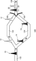
- Fig. 1 shows an example of a block diagram of a quantum computer 100.
- Fig. 2 shows an example of a configuration of the quantum computer 100.
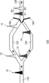
- Fig. 3A shows an example of a configuration of the qubit generation unit 120.
- Fig. 3B shows a variation of a configuration of the qubit generation unit 120.
- Fig. 3C shows a variation of a configuration of the qubit generation unit 120.
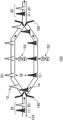
- Fig. 4 shows an example of a configuration of the quantum operation unit 160.
- Fig. 5A shows an example of a configuration of the operation processing unit 162.
- Fig. 5B shows an example of an implementation of the operation processing unit 162.
- Fig. 5C shows a variation of a configuration of the operation processing unit 162.
- Fig. 6 shows an example of an implementation of the propagation velocity adjustment unit 140.
- Fig. 7 shows an example of a configuration of the comparison unit 150.
- Fig. 8A shows a variation of a configuration of the quantum computer 100.
- Fig. 1 shows an example of a block diagram of the quantum computer 100.
- the quantum computer 100 of the present example includes an input unit 110, a qubit generation unit 120, and a propagation unit 130.
- the quantum computer 100 may include a propagation velocity adjustment unit 140, a comparison unit 150, a quantum operation unit 160, and an output unit 170.
- the quantum computer 100 is a computer which performs information processing based on the laws of quantum mechanics.
- the input unit 110 inputs an electron wave packet 10 described later.
- the input unit 110 may input the electron wave packet 10 into the propagation unit 130.
- the input unit 110 may input a plurality of electron wave packets 10.
- the input unit 110 may input the plurality of electron wave packets 10 into the propagation unit 130.
- the input unit 110 may have an electron wave packet generation unit 112.
- the electron wave packet generation unit 112 generates the electron wave packet 10.
- the electron wave packet generation unit 112 may generate the plurality of electron wave packets 10.
- the electron wave packet generation unit 112 may generate the electron wave packet 10 with a low deformation and relaxation and a high directionality.
- the electron wave packet 10 may be a plasmon generated by a short electronic pulse. In this case, the quantum decoherence can be reduced. In addition, the electron wave packet 10 can propagate semi-permanently due to the interaction between electrons. The electron wave packet 10 can propagate for a long distance with the quantum state maintained. Furthermore, because the electron wave packet 10 has a good directionality, the quantum computer 100 can propagate the electron wave packet 10 in an intended direction.
- the electron wave packet generation unit 112 may generate the electron wave packet 10 by using the Lorentz-type electronic pulse.
- the electron wave packet 10 with a low deformation and relaxation and a high directionality can be generated.
- the method for generating the electron wave packet 10 by the electron wave packet generation unit 112 is not limited thereto.
- the electron wave packet generation unit 112 may generate the electron wave packet 10 with any method for generating the electron wave packet 10 with a low deformation and relaxation and a high directionality.
- the electron wave packet generation unit 112 may be provided outside the input unit 110.
- the input unit 110 may input to the propagation unit 130 the electron wave packet 10 generated by the electron wave packet generation unit 112 provided outside the input unit 110.
- the qubit generation unit 120 generates the time-bin qubit 20 using the electron wave packet 10.
- the qubit generation unit 120 may generate a plurality of time-bin qubits 20 using the plurality of electron wave packets 10.
- the time-bin qubit 20 and the method for generating the same are described later.
- the propagation unit 130 propagates the electron wave packet 10 in a predetermine direction.
- the electron wave packet generation unit 112 generates the electron wave packet 10 with a high directionality so that the propagation unit 130 can propagate the electron wave packet 10 in the predetermined direction.
- the propagation unit 130 has a loop-like loop path 132.
- the propagation unit 130 may have a plurality of loop paths 132.
- the loop path 132 is described later.
- the propagation unit 130 may propagate the electron wave packet 10 in the predetermined direction of the loop path 132.
- the propagation velocity adjustment unit 140 adjusts the propagation velocity of the electron wave packet 10.
- the propagation velocity adjustment unit 140 may adjust the propagation velocity of the electron wave packet 10 by applying a gate voltage. Changing a gate voltage gently forms a barrier against the electron wave packet 10 and the substantial width of the path through which the electron wave packet 10 propagates may change. Because the propagation velocity of the electron wave packet 10 depends on the width of the path through which it propagates, the propagation velocity of the electron wave packet 10 may be adjusted by the gate voltage.
- the method for adjusting the propagation velocity of the electron wave packet 10 by the propagation velocity adjustment unit 140 is not limited thereto.
- the comparison unit 150 may compare the quantum states of at least two time-bin qubits 20 among the plurality of time-bin qubits 20.
- the at least two time-bin qubits 20, for which the quantum states is compared by the comparison unit 150 may be at least two time-bin qubits 20 that propagate with the propagation unit 130 being adjacent to each other or may be at least two time-bin qubits 20 that propagate with the propagation unit 130 not being adjacent to each other.
- the comparison unit 150 may transfer the comparison result to the modulation unit 166 described later.
- the comparison result of the comparison unit 150 may be used to correct a quantum error.
- the quantum operation unit 160 may operate the time-bin qubit 20.
- the quantum operation unit 160 may operate the plurality of time-bin qubits 20.
- the quantum operation unit 160 may have an operation processing unit 162, a quantum entanglement state generation unit 164, and a modulation unit 166.
- the operation processing unit 162 may control the quantum state of the time-bin qubit 20.
- the operation processing unit 162 may perform the quantum operation by controlling the quantum state of the time-bin qubit 20.
- the operation processing unit 162 may control the quantum state of the time-bin qubit 20 itself or may convert the time-bin qubit 20 into different types of qubits and control the quantum state of the converted qubit.
- the operation processing unit 162 may control the quantum state of the plurality of time-bin qubits 20.
- the quantum entanglement state generation unit 164 may generate the quantum entanglement state between at least two time-bin qubits 20.
- the quantum entanglement state generation unit 164 may generate the quantum entanglement state between at least two time-bin qubits 20 themselves or may convert at least two time-bin qubits 20 into different types of qubits and generate the quantum entanglement state between the converted qubits.
- the quantum entanglement state generation unit 164 may generate the quantum entanglement state by using the coulomb interaction between the electron wave packets.
- the modulation unit 166 may modulate the operation of the quantum state of the time-bin qubit 20.
- the modulation unit 166 may modulate the operation of the quantum state of the time-bin qubit 20 depending on the comparison result of the comparison unit 150.
- the modulation unit 166 may modulate the operation of the quantum state of the plurality of time-bin qubits 20 depending on the comparison result of the comparison unit 150.
- the quantum operation unit 160 may be a component that is responsible for the general quantum operation.
- the components included in the quantum operation unit 160 are not limited to the operation processing unit 162, the quantum entanglement state generation unit 164, and the modulation unit 166.
- the quantum operation unit 160 may have another component that performs the quantum operation.
- the output unit 170 may extract the time-bin qubit 20 from the propagation unit 130.
- the output unit 170 may extract the plurality of time-bin qubits 20 from the propagation unit 130.
- the time-bin qubit 20 extracted by the output unit 170 may be used for destructive final reading of the quantum state.
- the time-bin qubit 20 having a quantum error may be erased from the propagation unit 130 by being extracted by the output unit 170.
- the output unit 170 may selectively extract the time-bin qubit 20 used for the destructive final reading of the quantum state and/or the time-bin qubit 20 having the quantum error to be erased from the propagation unit 130.
- the quantum computer 100 may detect the quantum error based on the comparison result of the comparison unit 150. If the quantum computer 100 detects the quantum error, it may erase from the propagation unit 130 the time-bin qubit 20 having the quantum error by the output unit 170. The quantum computer 100 may input a new electron wave packet 10 from the input unit 110 to the propagation unit 130, instead of the time-bin qubit 20 erased from the propagation unit 130. The quantum computer 100 may generate the new time-bin qubit 20 by using a newly input electron wave packet 10 by the qubit generation unit 120. In this manner, the quantum computer 100 may correct a quantum error.
- the quantum computer 100 may perform initialization of the time-bin qubit 20 propagating through the propagation unit 130 by using the extraction of the time-bin qubit 20 by the output unit 170 and the input of the electron wave packet 10 by the input unit 110 and the generation of the time-bin qubit 20 by the qubit generation unit 120.
- Fig. 2 shows an example of the configuration of the quantum computer 100.
- the propagation unit 130 of the present example has a loop-like loop path 132.
- the electron wave packet 10 is input to the propagation unit 130 by the input unit 110.
- the electron wave packet 10 may be input to the loop path 132.
- the electron wave packet 10 may propagate through the loop path 132 in the predetermined direction.
- the electron wave packet 10 of the present example propagates counter-clockwise through the loop path 132.
- the qubit generation unit 120 may be provided on the loop path 132.
- the electron wave packet 10 is used to generate the time-bin qubit 20 by the qubit generation unit 120.
- the time-bin qubit 20 may propagate through the loop path 132 in the predetermined direction.
- the electron wave packet 10 may propagate through the loop path 132as the electron wave packet 10, or may propagate through the loop path 132 as the time-bin qubit 20.
- the qubit generation unit 120 may be provided near the position at which the electron wave packet 10 is input, so that the electron wave packet 10 propagates through most of the loop path 132 as the time-bin qubit 20.
- the position at which the qubit generation unit 120 is provided is not limited thereto.
- the qubit generation unit 120 may use the electron wave packet 10 to generate the time-bin qubit 20 before the quantum operation is performed.
- the time-bin qubit 20 is the qubit represented as the superimposition between the state
- the time-bin qubit 20-1 is represented as ⁇ 1
- 1> 1 is higher than the existence probability of the electron wave packet of the preceding state
- 1> 1 with a higher existence probability is represented to be darker.
- 0> is higher than the probability of being in the delayed state
- the difference of the color strength between the two electron wave packets of the time-bin qubit 20-2 is smaller than the difference of the color strength between the two electron wave packets of the time-bin qubit 20-1.
- 1> is higher than the probability of the same being in the preceding state
- the time-bin qubit 20 is an example of a flying qubit that is a qubit defined for a moving particle. Because the quantum computer 100 of the present example uses the time-bin qubit 20, which requires no wiring to individual qubits, the hardware necessary for constructing the system can be dramatically downsized in comparison to the case where the localized qubit that is a qubit defined for the localized quantum two-level system is used. In addition, because the quantum computer 100 of the present example uses the time-bin qubit 20 of the electron wave packet 10, the generation of the quantum entanglement state is easier and the problem of photon loss does not occur in comparison to the light quantum computer using flying qubit comprised of photon. Thus, the quantum computer 100 of the present example can dramatically downsize the hardware necessary for constructing the system in comparison to the light quantum computer.
- 1> may be in the picosecond order.
- the change of the environment can be reduced in a period when the preceding state
- the quantum computer 100 of the present example can reduce the effect of the phase relaxation and reduce the quantum decoherence by propagating the time-bin qubit 20 to the loop path 132.
- the loop path 132 through which the time-bin qubit 20 is propagated may serve as a memory of the quantum computer 100 by preserving the quantum state of the time-bin qubit 20.
- the propagation unit 130 may propagate the plurality of time-bin qubits 20.
- the length of the electron wave packet 10 may be substantially shorter than the length of the loop path 132.
- the length of the electron wave packet 10 may be less than or equal to 1/1000000, less than or equal to 1/100000, less than or equal to 1/10000, less than or equal to 1/1000, or less than or equal to 1/100 of the length of the loop path 132.
- the output unit 170 may extract the time-bin qubit 20 from the loop path 132.
- the output unit 170 may selectively extract the time-bin qubit 20 to be used for destructive final reading of the quantum state and/or the time-bin qubit 20 having a quantum error to be erased from the loop path 132.
- the time-bin qubit 20 that was not extracted by the output unit 170 may continue to propagate through the loop path 132. In other words, the time-bin qubit 20 may continue to propagate through the loop path 132 by circulating through the same, and the time-bin qubit 20 that needs to be extracted may be extracted by the output unit 170 in a timely manner.
- FIG. 2 Another component not depicted in Fig. 2 may be provided on the loop path 132.
- the propagation velocity adjustment unit 140, the comparison unit 150, and the quantum operation unit 160 may be provided on any appropriate position of the loop path 132.
- the propagation velocity adjustment unit 140 may be provided on any position of the loop path 132.
- the propagation velocity adjustment unit 140 may adjust the propagation velocity of the electron wave packet 10 before the time-bin qubit 20 is generated, and may adjust the propagation velocity of the time-bin qubit 20.
- the comparison unit 150 may be provided after the qubit generation unit 120 in the loop path 132. In other words, the comparison unit 150 may compare the quantum state of the time-bin qubit 20. However, the comparison unit 150 may be provided before the qubit generation unit 120, and may compare the quantum state of the electron wave packet 10 before the time-bin qubit 20 is generated.
- the quantum operation unit 160 may be provided after the qubit generation unit 120 in the loop path 132. In other words, the quantum operation unit 160 may perform the quantum operation for the time-bin qubit 20.
- Each constituent included in the quantum operation unit 160 may be integrally provided or may be discretely provided.
- the operation processing unit 162, the quantum entanglement state generation unit 164, and the modulation unit 166 may be integrally provided to be adjacent to each other, or may be provided at different positions from each other in the loop path 132.
- the operation processing unit 162, the quantum entanglement state generation unit 164, and the modulation unit 166 constitute the quantum operation unit 160, which does not necessarily mean that all the components are integrally provided in the loop path 132.
- a common quantum operation unit 160 is provided for the plurality of time-bin qubits 20 that propagate through the loop path 132. This can significantly reduce the requirement of the hardware necessary for the configuration of the quantum computer 100.
- Fig. 3A shows an example of the configuration of the qubit generation unit 120.
- the qubit generation unit 120 of the present example has a first path 122, a second path 124, and a common path 126.
- the qubit generation unit 120 may have a switch gate 180.
- the first path 122 is provided on the loop path 132.
- the second path 124 branches off from the first path 122.
- the common path 126 is connected to the first path 122 and the second path 124, and generates the time-bin qubit 20 by using the first electron wave packet 12 propagated from the first path 122 and the second electron wave packet 14 propagated from the second path 124.
- the common path 126 may constitute a part of the loop path 132.
- the qubit generation unit 120 may generate the time-bin qubit 20 by causing the electron wave packet 10 to branch into the first electron wave packet 12 and the second electron wave packet 14 using the first path 122 and the second path 124, and then causing the first electron wave packet 12 and the second electron wave packet 14 to merge into the common path 126. Because the time-bin qubit 20 is generated from one electron wave packet 10, it can be represented as the superimposition of the preceding state
- the duration from the time when the first electron wave packet 12 is input to the first path 122 to the time when it is input to the common path 126 may be shorter than the duration from the time when the second electron wave packet 14 is input to the second path 124 to the time when it is input to the common path 126.
- the propagation velocity of the first electron wave packet 12 in the first path 122 may be higher than the propagation velocity of the second electron wave packet 14 in the second path 124.
- the duration from the time when the first electron wave packet 12 is input to the first path 122 to the time when it is input to the common path 126 can be shorter than the duration from the time when the second electron wave packet 14 is input to the second path 124 to the time when it is input to the common path 126.
- the propagation velocity adjustment unit 140 may adjust the propagation velocity of the electron wave packet in the first path 122 and/or the second path 124.
- the propagation velocity adjustment unit 140 may adjust the propagation velocity of the first electron wave packet 12 in the first path 122 to be higher, may adjust the propagation velocity of the second electron wave packet 14 in the second path 124 to be slower, or may adjust the both.
- the switch gate 180 may prevent the electron wave packet input from one of the first path 122 and the second path 124 to the common path 126 from entering the other of the first path 122 and the second path 124. In other words, if the first electron wave packet 12 is output from the first path 122, the switch gate 180 may prevent the first electron wave packet 12 from entering the second path 124; or if the second electron wave packet 14 is output from the second path 124, the switch gate 180 may prevent the second electron wave packet 14 from entering the first path 122. If the first electron wave packet 12 is output from the first path 122, the switch gate 180 provided on the first path 122 is controlled to be in a passable state and the switch gate 180 provided on the second path 124 is controlled to be in an impassable state.
- the first electron wave packet 12 is input to the common path 126 without entering the second path 124. If the second electron wave packet 14 is output from the second path 124, the switch gate 180 provided on the first path 122 is controlled to be in an impassable state, and the switch gate 180 provided on the second path 124 is controlled to be in an passable state. Thus, the second electron wave packet 14 is input to the common path 126 without entering the first path 122.
- Fig. 3B shows a variation of the configuration of the qubit generation unit 120.
- the length of the first path 122 is shorter than the length of the second path 124.
- the duration from the time when the first electron wave packet 12 is input to the first path 122 to the time when it is input to the common path 126 can be shorter than the duration from the time when the second electron wave packet 14 is input to the second path 124 to the time when it is input to the common path 126.
- Fig. 3C shows a variation of a configuration of the qubit generation unit 120.
- the width of first path 122 is wider than the width of the second path 124.
- the propagation velocity of the first electron wave packet 12 in the first path 122 can be higher than the propagation velocity of the second electron wave packet 14 in the second path 124, and the duration from the time when the first electron wave packet 12 is input to the first path 122 to the time when it is input to the common path 126 can be shorter than the duration from the time when the second electron wave packet 14 is input to the second path 124 to the time when it is input to the common path 126.
- the width of all parts of the first path 122 of the present example is wider than the width of the second path 124.
- the width of at least a part of the first path 122 may be wider than the width of the second path 124.
- the width of at least part of the second path 124 may be narrower than the width of the first path 122.
- the difference in the propagation velocity of the electron wave packet between the first path 122 and the second path 124 can be adjusted by changing the width of at least part of the first path 122 and/or the second path 124.
- the qubit generation unit 120 may generate the time-bin qubit 20 by adjusting the propagation velocity as described in the example of Fig. 3A, may generate the time-bin qubit 20 by adjusting the path length as shown in the example of Fig. 3B, or may generate the time-bin qubit 20 by adjusting the path width as shown in the example of Fig. 3C. Alternatively, the qubit generation unit 120 may generate the time-bin qubit 20 through any combination of these. However, the method for generating the time-bin qubit 20 by the qubit generation unit 120 is not limited thereto.
- Fig. 4 shows an example of the configuration of the quantum operation unit 160.
- the quantum operation unit 160 of the present example has a first operation path 1602, a second operation path 1606, and an operation processing unit 162.
- the quantum operation unit 160 may have a first delay path 1604 and a second delay path 1608.
- the first operation path 1602 is provided on the loop path 132, and propagates the first electron wave packet 12 of the time-bin qubit 20.
- the second operation path 1606 branches off from the first operation path 1602 and propagates the second electron wave packet 14 of the time-bin qubit 20.
- the operation processing unit 162 controls the quantum state of at least one of the first electron wave packet 12 and the second electron wave packet 14.
- the quantum operation unit 160 may convert the time-bin qubit 20 into a which-path qubit 30 and then perform the quantum operation for the which-path qubit 30.
- the exemplary configuration of the operation processing unit 162 is described later.
- the which-path qubit 30 is the qubit represented as the superimposition between the state
- 0> represents the state of the first electron wave packet 12 propagating through the first operation path 1602
- 1> represents the state of the second electron wave packet 14 propagating through the second operation path 1606.
- 0> of the which-path qubit 30 may inherit the preceding state
- 1> of the which-path qubit 30 may inherit the delayed state
- the quantum state may be preserved before and after the conversion from the time-bin qubit 20 into the which-path qubit 30.
- the quantum operation unit 160 may control the switch gate 180 such that only the electron wave packet of the preceding state
- the quantum state can be preserved before and after the conversion from the time-bin qubit 20 into the which-path qubit 30.
- the first delay path 1604 is provided on the first operation path 1602 and delays the first electron wave packet 12 and inputs it to the operation processing unit 162. Because the first electron wave packet 12 corresponds to the electron wave packet of the preceding state
- the first delay path 1604 delays the first electron wave packet 12 to compensate for the time lag existing in the state of the time-bin qubit 20, allowing the configuration of the which-path qubit 30 that is represented as the superimposition of the upper path state
- the second delay path 1608 is provided on the second operation path 1606 and delays the second electron wave packet 14, for which the quantum state is controlled by the operation processing unit 162. By delaying the second electron wave packet 14 that has passed through the operation processing unit 162, the first electron wave packet 12 and the second electron wave packet 14 can be propagated through the loop path 132 as the time-bin qubit 20 again.
- the quantum computer 100 of the present example circulates the electron wave packet 10 through the loop path 132 in the state of the time-bin qubit 20, and converts the time-bin qubit 20 into the which-path qubit 30 by quantum operation unit 160.
- the quantum decoherence occurring during the propagation can be reduced.
- the propagation of the time-bin qubit 20 can be performed with a single-line circuit, the electric circuit can be simplified in comparison to the case where the electron wave packet 10 is propagated in the state of the which-path qubit 30.
- the quantum computer 100 may perform the quantum operation on the time-bin qubit 20 itself without converting the time-bin qubit 20 into the which-path qubit 30 by the quantum operation unit 160.
- Fig. 5A shows an example of the configuration of the operation processing unit 162.
- the operation processing unit 162 of the present example includes a NOT circuit. For example, it is assumed that which-path qubit 30 is input to the operation processing unit 162 with the existence probability mostly biased to the upper path state
- the operation processing unit 162 may control the quantum state of the first electron wave packet 12 propagating through the first operation path 1602 and the second electron wave packet 14 propagating through the second operation path 1606 to output the which-path qubit 30 with the existence probability mostly biased to the lower path state
- the circuit included in the operation processing unit 162 is not limited thereto.
- the operation processing unit 162 may include an AND circuit, may include an OR circuit, and may include any other operation processing circuit.
- the operation processing unit 162 may arbitrarily control the quantum state of the which-path qubit 30.
- Fig. 5B indicates an example of an implementation of the operation processing unit 162.
- the operation processing unit 162 may have a plurality of gate electrode structures.
- the first operation path 1602 and the second operation path 1606 may be provided as a region between the plurality of gate electrode structures.
- the operation processing unit 162 may have a first gate electrode 1622, a second gate electrode 1624, a third gate electrode 1626, and a fourth gate electrode 1628.
- the operation processing unit 162 of the present example controls the quantum state of the which-path qubit 30 by using each gate electrode to apply a gate voltage V T1 , V T2 , V M1 , and V M2 .
- the implementation method of the operation processing unit 162 is not limited thereto.
- the operation processing unit 162 may be implemented such that the quantum state of the which-path qubit 30 can be controlled.
- the modulation unit 166 may modulate the operation of the quantum state of the which-path qubit 30 and hence may modulate the operation of the quantum state of the time-bin qubit 20 by modulating the gate voltage V T1 , V T2 , V M1 , and V M2 applied by each gate electrode.
- the modulation unit 166 may modulate the operation of the quantum state of the which-path qubit 30 by modulating the gate voltage V T1 , V T2 , V M1 , and V M2 applied by each gate electrode depending on the comparison result of the comparison unit 150.
- Fig. 5C shows a variation of the configuration of the operation processing unit 162.
- the operation processing unit 162 of the present example controls the quantum state between the which-path qubit 30-1 into which the first time-bin qubit 20-1 is converted and the which-path qubit 30-2 into which the second time-bin qubit 20-2 that is different from the first time-bin qubit 20-1 is converted.
- the first time-bin qubit 20-1 and the second time-bin qubit 20-2 may be two time-bin qubits 20 that propagate through the same loop path 132 with being adjacent to each other, or may be two time-bin qubits 20 that propagate through the same loop path 132 with not being adjacent to each other.
- first time-bin qubit 20-1 and the second time-bin qubit 20-2 may be two time-bin qubits 20 propagating through different loop paths 132.
- the operation processing unit 162 may perform the dual qubit operation using any two time-bin qubits 20. That dual qubit operation can be achieved by using any delay circuit exemplified with respect to Fig. 3A to Fig. 4. The case where the propagation unit 130 having a plurality of loop paths 132 will be described later.
- the operation processing unit 162 of the present example causes the second electron wave packet 14 of the which-path qubit 30-1 propagating through the second operation path 1606 and the first electron wave packet 12 of the which-path qubit 30-2 propagating through the first operation path 1602 to interact with each other, to control the coupling of the quantum state between the which-path qubit 30-1 and the which-path qubit 30-2 and perform the dual qubit operation.
- the operation processing unit 162 may also cause the first electron wave packets 12 to interact with each other, or cause the second electron wave packets 14 to interact with each other.
- the configuration of the operation processing unit 162 of the present example may be used for the quantum entanglement state generation unit 164.
- the quantum entanglement state generation unit 164 may cause the second electron wave packet 14 of the which-path qubit 30-1 into which the first time-bin qubit 20-1 is converted and the first electron wave packet 12 of the which-path qubit 30-2 into which the second time-bin qubit 20-2 is converted to interact with each other, to generate the quantum entanglement state between the first time-bin qubit 20-1 and the second time-bin qubit 20-2.
- the quantum entanglement state generation unit 164 may generate the quantum entanglement state between any two time-bin qubits 20.
- the quantum entanglement state generation unit 164 also generates a quantum entanglement state between the first time-bin qubit 20-1 propagating through the loop path 132 and the second time-bin qubit 20-2 propagating through the same loop path 132 and propagating via another path branching off in the same loop path 132.
- the size of the control system is proportional to N x .
- the size of the control system with the increased number of qubits N can be smaller.
- the exponent x of the size of the control system is 0.5. Because the quantum computer 100 of the present example can perform the quantum operation not only between two adjacent qubits but also between any two qubits, the exponent x of the size of the control system is smaller than 0.5. Thus, a large number of qubits can be controlled by small hardware, and the problem of scalability can be resolved.
- Fig. 6 shows an example of the implementation of the propagation velocity adjustment unit 140.
- the propagation velocity adjustment unit 140 of the present example has a first voltage application unit 142 and a second voltage application unit 144.
- the propagation velocity adjustment unit 140 may have a plurality of gate electrode structures.
- the loop path 132 may be provided as a region between the plurality of gate electrode structures.
- the first voltage application unit 142 is provided on the loop path 132.
- the second voltage application unit 144 is provided at a predetermined distance from the first voltage application unit 142 in the loop path 132.
- the propagation velocity adjustment unit 140 can adjust the propagation velocity of the electron wave packet 10 by applying the gate voltage to two parts including the first voltage application unit 142 and the second voltage application unit 144, without applying the gate voltage to all parts for which the rate is to be adjusted. Thus, in comparison to applying the gate voltage to all parts for which the rate is to be adjusted, the effect on the surrounding system can be reduced. However, the propagation velocity adjustment unit 140 may adjust the propagation velocity of the electron wave packet 10 by applying the gate voltage to the entire parts for which the rate is to be adjusted.
- the propagation velocity adjustment unit 140 of the present example is provided on the loop path 132, the propagation velocity adjustment unit 140 may be provided on a part of another configuration, such as the first path 122, the second path 124, the first delay path 1604, and the second delay path 1608.
- Fig. 7 shows an example of a configuration of the comparison unit 150.
- the comparison unit 150 of the present example has double quantum dots 152.
- the double quantum dots 152 are two quantum dots that are tunnel-coupled to each other.
- the double quantum dot 152 may be provided near the propagation path of the electron wave packet. Because the spin exchange coupling of the double quantum dots 152 is modulated due to the propagation of the electron wave packet, the quantum state of the electron wave packet can be read non-destructively by reading the spin state.
- the method for reading the quantum state by the comparison unit 150 is not limited thereto.
- the qubit of the two electron wave packets may be compared by selectively causing the electron wave packet having the qubit of the same parity to transmit, using the modulation of propagation trajectory through the coulomb interaction between the electron wave packets.
- the comparison unit 150 may read the quantum state of the which-path qubit 30 after converting the time-bin qubit 20 into the which-path qubit 30.
- the comparison unit 150 of the present example has double quantum dots 152 on each of the propagation path of the first electron wave packet 12 and the propagation path of the second electron wave packet 14 of the which-path qubit 30, and reads the quantum state of each of the first electron wave packet 12 and the second electron wave packet 14.
- the comparison unit 150 may read the quantum state of at least one of the first electron wave packet 12 and the second electron wave packet 14.
- the comparison unit 150 may re-convert the which-path qubits 30 into the time-bin qubits 20 after reading the quantum state.
- the comparison unit 150 may compare the quantum states of at least two time-bin qubits 20 among the plurality of time-bin qubits 20 that propagate through the loop path 132. In other words, the comparison unit 150 may convert the at least two time-bin qubits 20 into at least two which-path qubits 30 and compare the quantum states of at least two which-path qubits 30. The comparison unit 150 may sequentially read the quantum states of the at least two which-path qubits 30 through the method described above and compare the quantum states of at least two which-path qubits 30.
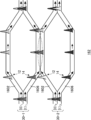
- Fig. 8A shows a variation of a configuration of the quantum computer 100.
- the propagation unit 130 of the present example has a plurality of loop paths 132. Although the propagation unit 130 of the present example has two loop paths 132 including the first loop path 134 and the second loop path 136, the number of the loop paths 132 included in the propagation unit 130 and their relative positional relationship are not limited thereto.
- the propagation unit 130 may have one loop path 132 and may have three or more loop paths 132.
- the first loop path 134 and the second loop path 136 may be arranged in parallel with each other, or may not be arranged in parallel with each other.
- the first loop path 134 and the second loop path 136 being arranged in parallel with each other may refer to one loop path 132 being arranged to surround the other loop path 132.
- the first loop path 134 and the second loop path 136 may cross each other or may not cross each other.
- the first loop path 134 and the second loop path 136 may have a common input unit 110 and/or output unit 170, and may each have the input unit 110 and/or the output unit 170.
- the first loop path 134 and the second loop path 136 in the present example each has the input unit 110 and the output unit 170.
- the quantum computer 100 may include a common quantum operation unit 160 on plurality of loop paths 132.
- the quantum computer 100 of the present example includes a common quantum operation unit 160 on the first loop path 134 and the second loop path 136.
- the quantum operation unit 160 may perform the quantum operation for different time-bin qubits 20 that propagate through different loop paths 132.
- Fig. 8 shows a variation of a configuration of the quantum operation unit 160.
- the quantum operation unit 160 of the present example has a quantum entanglement state generation unit 164.
- the quantum entanglement state generation unit 164 may generate the quantum entanglement state between the first time-bin qubit 20-1 propagating through the first loop path 134 and the second time-bin qubit 20-2 propagating through the second loop path 136, which is different from the first loop path 134.
- the quantum entanglement state generation unit 164 may convert the time-bin qubit 20 propagating through each loop path 132 into the which-path qubit 30.
- the quantum entanglement state generation unit 164 of the present example converts the time-bin qubit 20-1 propagating through the first loop path 134 into the which-path qubit 30-1, and converts the time-bin qubit 20-2 propagating through the second loop path 136 into the which-path qubit 30-2.
- the quantum entanglement state generation unit 164 may cause the second electron wave packet 14 of the which-path qubit 30-1 into which the first time-bin qubit 20-1 is converted and the first electron wave packet 12 of the which-path qubit 30-2 into which the second time-bin qubit 20-2 is converted to interact with each other, to generate the quantum entanglement state between the first time-bin qubit 20-1 and the second time-bin qubit 20-2.
- the quantum entanglement state generation unit 164 may cause the first electron wave packets 12 to interact with each other, or cause the second electron wave packets 14 to interact with each other.
- the quantum entanglement state generation unit 164 of the present example generates the quantum entanglement state between the time-bin qubits 20 propagating through different loop paths 132. This can ensure the redundancy of the qubit information in the quantum error correction and can efficiently and reliably correct the quantum error.
- the configuration of the quantum entanglement state generation unit 164 of the present example may be used for the operation processing unit 162.
- the operation processing unit 162 may cause the second electron wave packet 14 of the which-path qubit 30-1 into which the first time-bin qubit 20-1 is converted and the first electron wave packet 12 of the which-path qubit 30-2 into which the second time-bin qubit 20-2 is converted to interact with each other, to control the coupling of the quantum state between the which-path qubit 30-1 and the which-path qubit 30-2 and perform the dual qubit operation.
Landscapes
- Engineering & Computer Science (AREA)
- General Physics & Mathematics (AREA)
- Theoretical Computer Science (AREA)
- Physics & Mathematics (AREA)
- Mathematical Analysis (AREA)
- Data Mining & Analysis (AREA)
- Evolutionary Computation (AREA)
- Condensed Matter Physics & Semiconductors (AREA)
- Computational Mathematics (AREA)
- Mathematical Optimization (AREA)
- Pure & Applied Mathematics (AREA)
- Computing Systems (AREA)
- General Engineering & Computer Science (AREA)
- Mathematical Physics (AREA)
- Software Systems (AREA)
- Artificial Intelligence (AREA)
- Optical Modulation, Optical Deflection, Nonlinear Optics, Optical Demodulation, Optical Logic Elements (AREA)
Abstract
Provided is a quantum computer, including: an input unit for inputting an electron wave packet; a propagation unit that propagates the electron wave packet in a predetermined direction and has a loop-like loop path; and a qubit generation unit that generates a time-bin qubit by using the electron wave packet.
Description
The present invention relates to a quantum computer.
Non-Patent Document 1 describes 'fling qubit' architectures-systems.
Citation List
Non-Patent Literature
Non-Patent Document 1: Michihisa Yamamoto, et. al., "Electrical control of a solid-state flying qubit," NATURE NANOTECHNOLOGY, 18 March, 2012, Vol. 7, p. 247-251
Non-Patent Document 2: Hermann Edlbauer, et. al., "Semiconductor-based electron flying qubits: review on recent progress accelerated by numerical modeling," EPJ Quantum Technology, 10 August, 2022, Vol.9, 21
Citation List
Non-Patent Literature
Non-Patent Document 1: Michihisa Yamamoto, et. al., "Electrical control of a solid-state flying qubit," NATURE NANOTECHNOLOGY, 18 March, 2012, Vol. 7, p. 247-251
Non-Patent Document 2: Hermann Edlbauer, et. al., "Semiconductor-based electron flying qubits: review on recent progress accelerated by numerical modeling," EPJ Quantum Technology, 10 August, 2022, Vol.9, 21
In an aspect of the present invention, a quantum computer is provided, which includes an input unit for inputting an electron wave packet; a propagation unit that propagates the electron wave packet in a predetermined direction and has a loop-like loop path; and a qubit generation unit that generates a time-bin qubit by using the electron wave packet.
In the quantum computer described above, the qubit generation unit may have a first path provided on the loop path. The qubit generation unit may have a second path that branches off from the first path. The qubit generation unit may include a common path that is connected to the first path and the second path, for generating the time-bin qubit using a first electron wave packet propagating from the first path and a second electron wave packet propagating from the second path.
In any quantum computer described above, a duration from a time when the first electron wave packet is input to the first path to a time when it is input to the common path may be shorter than a duration from a time when the second electron wave packet is input to the second path to a time when it is input to the common path.
In any quantum computer described above, the propagation velocity of the first electron wave packet in the first path may be higher than the propagation velocity of the second electron wave packet in the second path.
In any quantum computer described above, the length of the first path may be shorter than the length of the second path.
In any quantum computer described above, the width of the first path may be wider than the width of the second path.
In any quantum computer described above, the qubit generation unit may include a switch gate that prevents an electron wave packet that is input from one of the first path and the second path to the common path from entering the other of the first path and the second path.
Any quantum computer described above may include a quantum operation unit for operating the time-bin qubit. The quantum operation unit may include a first operation path that is provided on the loop path and through which the first electron wave packet of the time-bin qubit is propagated; a second operation path that branches off from the first operation path and through which the second electron wave packet of the time-bin qubit is propagated; and an operation processing unit that controls a quantum state of at least one of the first electron wave packet and the second electron wave packet.
In any quantum computer described above, the quantum operation unit may include: a first delay path that is provided on the first operation path and delays the first electron wave packet and inputs it to the operation processing unit; and a second delay path that is provided on the second operation path and delays the second electron wave packet for which a quantum state is controlled by the operation processing unit.
In any quantum computer described above, the input unit may have an electron wave packet generation unit that generates the electron wave packet.
Any quantum computer described above may include an output unit that extracts the time-bin qubit from the propagation unit.
In any quantum computer described above, the propagation unit may have a plurality of loop paths.
Any quantum computer described above may include a quantum operation unit for operating the time-bin qubit. The quantum operation unit may include a quantum entanglement state generation unit that generates a quantum entanglement state between a first time-bin qubit that propagates through the first loop path among the plurality of loop paths and a second time-bin qubit that propagates through a second loop path, which is different from the first loop path.
Any quantum computer described above may include a propagation velocity adjustment unit that applies a negative gate voltage and adjusts the propagation velocity of the electron wave packet.
In any quantum computer described above, the propagation velocity adjustment unit may include a first voltage application unit provided on the loop path; and a second voltage application unit provided at a predetermine distance from the first voltage application unit in the loop path.
In any quantum computer described above, the input unit may input a plurality of electron wave packets. The qubit generation unit may generate the plurality of time-bin qubits by using the plurality of electron wave packets. The propagation unit may propagate the plurality of time-bin qubits.
Any quantum computer described above may include a quantum operation unit for operating the plurality of time-bin qubits. The quantum operation unit may include a operation processing unit that controls the quantum state between the which-path qubit into which the first time-bin qubit among the plurality of time-bin qubits is converted and the which-path qubit into which a second time-bin qubit, which is different from the first time-bin qubit, is converted.
Any quantum computer described above may include a comparison unit that compares the quantum states of the at least two time-bin qubits among the plurality of time-bin qubits.
In any quantum computer described above, the comparison unit may convert the at least two time-bin qubits into at least two which-path qubits and compare the quantum states of the at least two which-path qubits.
Any quantum computer described above may include a quantum operation unit for operating the plurality of time-bin qubits. The quantum operation unit may include a modulation unit that modulates the operation of the quantum state of the plurality of time-bin qubits depending on the comparison result of the comparison unit.
The summary clause does not necessarily describe all necessary features of the embodiments of the present invention. The present invention may also be a sub-combination of the features described above.
Hereinafter, the present invention will be described through embodiments of the invention, but the following embodiments do not limit the invention according to claims. In addition, not all of the combinations of features described in the embodiments are essential to the solution of the invention.
Fig. 1 shows an example of a block diagram of the quantum computer 100. The quantum computer 100 of the present example includes an input unit 110, a qubit generation unit 120, and a propagation unit 130. The quantum computer 100 may include a propagation velocity adjustment unit 140, a comparison unit 150, a quantum operation unit 160, and an output unit 170. The quantum computer 100 is a computer which performs information processing based on the laws of quantum mechanics.
The input unit 110 inputs an electron wave packet 10 described later. The input unit 110 may input the electron wave packet 10 into the propagation unit 130. The input unit 110 may input a plurality of electron wave packets 10. The input unit 110 may input the plurality of electron wave packets 10 into the propagation unit 130. The input unit 110 may have an electron wave packet generation unit 112.
The electron wave packet generation unit 112 generates the electron wave packet 10. The electron wave packet generation unit 112 may generate the plurality of electron wave packets 10. The electron wave packet generation unit 112 may generate the electron wave packet 10 with a low deformation and relaxation and a high directionality.
The electron wave packet 10 may be a plasmon generated by a short electronic pulse. In this case, the quantum decoherence can be reduced. In addition, the electron wave packet 10 can propagate semi-permanently due to the interaction between electrons. The electron wave packet 10 can propagate for a long distance with the quantum state maintained. Furthermore, because the electron wave packet 10 has a good directionality, the quantum computer 100 can propagate the electron wave packet 10 in an intended direction.
As an example, the electron wave packet generation unit 112 may generate the electron wave packet 10 by using the Lorentz-type electronic pulse. Thus, the electron wave packet 10 with a low deformation and relaxation and a high directionality can be generated. However, the method for generating the electron wave packet 10 by the electron wave packet generation unit 112 is not limited thereto. The electron wave packet generation unit 112 may generate the electron wave packet 10 with any method for generating the electron wave packet 10 with a low deformation and relaxation and a high directionality.
Although the input unit 110 having the electron wave packet generation unit 112 is described above, the electron wave packet generation unit 112 may be provided outside the input unit 110. In other words, the input unit 110 may input to the propagation unit 130 the electron wave packet 10 generated by the electron wave packet generation unit 112 provided outside the input unit 110.
The qubit generation unit 120 generates the time-bin qubit 20 using the electron wave packet 10. The qubit generation unit 120 may generate a plurality of time-bin qubits 20 using the plurality of electron wave packets 10. The time-bin qubit 20 and the method for generating the same are described later.
The propagation unit 130 propagates the electron wave packet 10 in a predetermine direction. The electron wave packet generation unit 112 generates the electron wave packet 10 with a high directionality so that the propagation unit 130 can propagate the electron wave packet 10 in the predetermined direction.
The propagation unit 130 has a loop-like loop path 132. The propagation unit 130 may have a plurality of loop paths 132. The loop path 132 is described later. The propagation unit 130 may propagate the electron wave packet 10 in the predetermined direction of the loop path 132.
The propagation velocity adjustment unit 140 adjusts the propagation velocity of the electron wave packet 10. The propagation velocity adjustment unit 140 may adjust the propagation velocity of the electron wave packet 10 by applying a gate voltage. Changing a gate voltage gently forms a barrier against the electron wave packet 10 and the substantial width of the path through which the electron wave packet 10 propagates may change. Because the propagation velocity of the electron wave packet 10 depends on the width of the path through which it propagates, the propagation velocity of the electron wave packet 10 may be adjusted by the gate voltage. However, the method for adjusting the propagation velocity of the electron wave packet 10 by the propagation velocity adjustment unit 140 is not limited thereto.
The comparison unit 150 may compare the quantum states of at least two time-bin qubits 20 among the plurality of time-bin qubits 20. The at least two time-bin qubits 20, for which the quantum states is compared by the comparison unit 150, may be at least two time-bin qubits 20 that propagate with the propagation unit 130 being adjacent to each other or may be at least two time-bin qubits 20 that propagate with the propagation unit 130 not being adjacent to each other. The comparison unit 150 may transfer the comparison result to the modulation unit 166 described later. The comparison result of the comparison unit 150 may be used to correct a quantum error.
The quantum operation unit 160 may operate the time-bin qubit 20. The quantum operation unit 160 may operate the plurality of time-bin qubits 20. The quantum operation unit 160 may have an operation processing unit 162, a quantum entanglement state generation unit 164, and a modulation unit 166.
The operation processing unit 162 may control the quantum state of the time-bin qubit 20. The operation processing unit 162 may perform the quantum operation by controlling the quantum state of the time-bin qubit 20. The operation processing unit 162 may control the quantum state of the time-bin qubit 20 itself or may convert the time-bin qubit 20 into different types of qubits and control the quantum state of the converted qubit. The operation processing unit 162 may control the quantum state of the plurality of time-bin qubits 20.
The quantum entanglement state generation unit 164 may generate the quantum entanglement state between at least two time-bin qubits 20. The quantum entanglement state generation unit 164 may generate the quantum entanglement state between at least two time-bin qubits 20 themselves or may convert at least two time-bin qubits 20 into different types of qubits and generate the quantum entanglement state between the converted qubits. The quantum entanglement state generation unit 164 may generate the quantum entanglement state by using the coulomb interaction between the electron wave packets.
The modulation unit 166 may modulate the operation of the quantum state of the time-bin qubit 20. The modulation unit 166 may modulate the operation of the quantum state of the time-bin qubit 20 depending on the comparison result of the comparison unit 150. The modulation unit 166 may modulate the operation of the quantum state of the plurality of time-bin qubits 20 depending on the comparison result of the comparison unit 150.
The quantum operation unit 160 may be a component that is responsible for the general quantum operation. In other words, the components included in the quantum operation unit 160 are not limited to the operation processing unit 162, the quantum entanglement state generation unit 164, and the modulation unit 166. The quantum operation unit 160 may have another component that performs the quantum operation.
The output unit 170 may extract the time-bin qubit 20 from the propagation unit 130. The output unit 170 may extract the plurality of time-bin qubits 20 from the propagation unit 130. The time-bin qubit 20 extracted by the output unit 170 may be used for destructive final reading of the quantum state. The time-bin qubit 20 having a quantum error may be erased from the propagation unit 130 by being extracted by the output unit 170. In other words, the output unit 170 may selectively extract the time-bin qubit 20 used for the destructive final reading of the quantum state and/or the time-bin qubit 20 having the quantum error to be erased from the propagation unit 130.
The quantum computer 100 may detect the quantum error based on the comparison result of the comparison unit 150. If the quantum computer 100 detects the quantum error, it may erase from the propagation unit 130 the time-bin qubit 20 having the quantum error by the output unit 170. The quantum computer 100 may input a new electron wave packet 10 from the input unit 110 to the propagation unit 130, instead of the time-bin qubit 20 erased from the propagation unit 130. The quantum computer 100 may generate the new time-bin qubit 20 by using a newly input electron wave packet 10 by the qubit generation unit 120. In this manner, the quantum computer 100 may correct a quantum error. In addition, the quantum computer 100 may perform initialization of the time-bin qubit 20 propagating through the propagation unit 130 by using the extraction of the time-bin qubit 20 by the output unit 170 and the input of the electron wave packet 10 by the input unit 110 and the generation of the time-bin qubit 20 by the qubit generation unit 120.
Fig. 2 shows an example of the configuration of the quantum computer 100. The propagation unit 130 of the present example has a loop-like loop path 132.
The electron wave packet 10 is input to the propagation unit 130 by the input unit 110. The electron wave packet 10 may be input to the loop path 132. The electron wave packet 10 may propagate through the loop path 132 in the predetermined direction. The electron wave packet 10 of the present example propagates counter-clockwise through the loop path 132.
The qubit generation unit 120 may be provided on the loop path 132. The electron wave packet 10 is used to generate the time-bin qubit 20 by the qubit generation unit 120. The time-bin qubit 20 may propagate through the loop path 132 in the predetermined direction. The electron wave packet 10 may propagate through the loop path 132as the electron wave packet 10, or may propagate through the loop path 132 as the time-bin qubit 20. As an example, the qubit generation unit 120 may be provided near the position at which the electron wave packet 10 is input, so that the electron wave packet 10 propagates through most of the loop path 132 as the time-bin qubit 20. However, the position at which the qubit generation unit 120 is provided is not limited thereto. The qubit generation unit 120 may use the electron wave packet 10 to generate the time-bin qubit 20 before the quantum operation is performed.
The time-bin qubit 20 is the qubit represented as the superimposition between the state |0> of the preceding electron wave packet (hereinafter, preceding state |0>) and the state |1> of the delayed electron wave packet (hereinafter, delayed state |1>). For example, the time-bin qubit 20-1 is represented as α1 |0>1 + β1 |1>1, wherein the α1 is the coefficient of the preceding state |0>1 and the β1 is the coefficient of the delayed state |1>1. In the time-bin qubit 20-1, the existence probability of the electron wave packet of the delayed state |1>1 is higher than the existence probability of the electron wave packet of the preceding state |0>1, and α1<β1. In the figure, the electron wave packet of the delayed state |1>1 with a higher existence probability is represented to be darker. In the time-bin qubit 20-2, the probability of being in the preceding state |0> is higher than the probability of being in the delayed state |1>, but the difference of the existence probability is smaller than the difference in the time-bin qubit 20-1, and β2-α2<β1-α1. In the figure, the difference of the color strength between the two electron wave packets of the time-bin qubit 20-2 is smaller than the difference of the color strength between the two electron wave packets of the time-bin qubit 20-1. In the time-bin qubit 20-N, the probability of the time-bin qubit 20-N being in the delayed state |1> is higher than the probability of the same being in the preceding state |0>.
The time-bin qubit 20 is an example of a flying qubit that is a qubit defined for a moving particle. Because the quantum computer 100 of the present example uses the time-bin qubit 20, which requires no wiring to individual qubits, the hardware necessary for constructing the system can be dramatically downsized in comparison to the case where the localized qubit that is a qubit defined for the localized quantum two-level system is used. In addition, because the quantum computer 100 of the present example uses the time-bin qubit 20 of the electron wave packet 10, the generation of the quantum entanglement state is easier and the problem of photon loss does not occur in comparison to the light quantum computer using flying qubit comprised of photon. Thus, the quantum computer 100 of the present example can dramatically downsize the hardware necessary for constructing the system in comparison to the light quantum computer.
The time difference between the preceding state |0> and the delayed state |1> may be in the picosecond order. Thus, the change of the environment can be reduced in a period when the preceding state |0> and the delayed state |1> pass, and the fluctuation with respect to the environment of the quantum state can be reduced. In other words, the quantum computer 100 of the present example can reduce the effect of the phase relaxation and reduce the quantum decoherence by propagating the time-bin qubit 20 to the loop path 132. The loop path 132 through which the time-bin qubit 20 is propagated may serve as a memory of the quantum computer 100 by preserving the quantum state of the time-bin qubit 20.
The propagation unit 130 may propagate the plurality of time-bin qubits 20. The length of the electron wave packet 10 may be substantially shorter than the length of the loop path 132. The length of the electron wave packet 10 may be less than or equal to 1/1000000, less than or equal to 1/100000, less than or equal to 1/10000, less than or equal to 1/1000, or less than or equal to 1/100 of the length of the loop path 132. With the length of the electron wave packet 10 that is substantially shorter than the length of the loop path 132, a large number of the time-bin qubits 20 can be propagated to the loop path 132 and the number of the time-bin qubits 20 and the memory capacity of the quantum computer 100 can be increased.
The output unit 170 may extract the time-bin qubit 20 from the loop path 132. The output unit 170 may selectively extract the time-bin qubit 20 to be used for destructive final reading of the quantum state and/or the time-bin qubit 20 having a quantum error to be erased from the loop path 132. The time-bin qubit 20 that was not extracted by the output unit 170 may continue to propagate through the loop path 132. In other words, the time-bin qubit 20 may continue to propagate through the loop path 132 by circulating through the same, and the time-bin qubit 20 that needs to be extracted may be extracted by the output unit 170 in a timely manner.
Another component not depicted in Fig. 2 may be provided on the loop path 132. In other words, the propagation velocity adjustment unit 140, the comparison unit 150, and the quantum operation unit 160 may be provided on any appropriate position of the loop path 132.
The propagation velocity adjustment unit 140 may be provided on any position of the loop path 132. The propagation velocity adjustment unit 140 may adjust the propagation velocity of the electron wave packet 10 before the time-bin qubit 20 is generated, and may adjust the propagation velocity of the time-bin qubit 20.
The comparison unit 150 may be provided after the qubit generation unit 120 in the loop path 132. In other words, the comparison unit 150 may compare the quantum state of the time-bin qubit 20. However, the comparison unit 150 may be provided before the qubit generation unit 120, and may compare the quantum state of the electron wave packet 10 before the time-bin qubit 20 is generated.
The quantum operation unit 160 may be provided after the qubit generation unit 120 in the loop path 132. In other words, the quantum operation unit 160 may perform the quantum operation for the time-bin qubit 20. Each constituent included in the quantum operation unit 160 may be integrally provided or may be discretely provided. In other words, the operation processing unit 162, the quantum entanglement state generation unit 164, and the modulation unit 166 may be integrally provided to be adjacent to each other, or may be provided at different positions from each other in the loop path 132. The operation processing unit 162, the quantum entanglement state generation unit 164, and the modulation unit 166 constitute the quantum operation unit 160, which does not necessarily mean that all the components are integrally provided in the loop path 132.
In the quantum computer 100 of the present example, a common quantum operation unit 160 is provided for the plurality of time-bin qubits 20 that propagate through the loop path 132. This can significantly reduce the requirement of the hardware necessary for the configuration of the quantum computer 100.
Fig. 3A shows an example of the configuration of the qubit generation unit 120. The qubit generation unit 120 of the present example has a first path 122, a second path 124, and a common path 126. The qubit generation unit 120 may have a switch gate 180.
The first path 122 is provided on the loop path 132. The second path 124 branches off from the first path 122. The common path 126 is connected to the first path 122 and the second path 124, and generates the time-bin qubit 20 by using the first electron wave packet 12 propagated from the first path 122 and the second electron wave packet 14 propagated from the second path 124. The common path 126 may constitute a part of the loop path 132. The qubit generation unit 120 may generate the time-bin qubit 20 by causing the electron wave packet 10 to branch into the first electron wave packet 12 and the second electron wave packet 14 using the first path 122 and the second path 124, and then causing the first electron wave packet 12 and the second electron wave packet 14 to merge into the common path 126. Because the time-bin qubit 20 is generated from one electron wave packet 10, it can be represented as the superimposition of the preceding state |0> and the delayed state |1>.
The duration from the time when the first electron wave packet 12 is input to the first path 122 to the time when it is input to the common path 126 may be shorter than the duration from the time when the second electron wave packet 14 is input to the second path 124 to the time when it is input to the common path 126. Thus, after the first electron wave packet 12 is input to the common path 126, the preceding state |0> is achieved and after the second electron wave packet 14 is input to the common path 126, the delayed state |1> is achieved, resulting in the generation of the time-bin qubit 20 having the preceding state |0> and the delayed state |1>.
The propagation velocity of the first electron wave packet 12 in the first path 122 may be higher than the propagation velocity of the second electron wave packet 14 in the second path 124. Thus, the duration from the time when the first electron wave packet 12 is input to the first path 122 to the time when it is input to the common path 126 can be shorter than the duration from the time when the second electron wave packet 14 is input to the second path 124 to the time when it is input to the common path 126. For example, the propagation velocity adjustment unit 140 may adjust the propagation velocity of the electron wave packet in the first path 122 and/or the second path 124. The propagation velocity adjustment unit 140 may adjust the propagation velocity of the first electron wave packet 12 in the first path 122 to be higher, may adjust the propagation velocity of the second electron wave packet 14 in the second path 124 to be slower, or may adjust the both.
The switch gate 180 may prevent the electron wave packet input from one of the first path 122 and the second path 124 to the common path 126 from entering the other of the first path 122 and the second path 124. In other words, if the first electron wave packet 12 is output from the first path 122, the switch gate 180 may prevent the first electron wave packet 12 from entering the second path 124; or if the second electron wave packet 14 is output from the second path 124, the switch gate 180 may prevent the second electron wave packet 14 from entering the first path 122. If the first electron wave packet 12 is output from the first path 122, the switch gate 180 provided on the first path 122 is controlled to be in a passable state and the switch gate 180 provided on the second path 124 is controlled to be in an impassable state. Thus, the first electron wave packet 12 is input to the common path 126 without entering the second path 124. If the second electron wave packet 14 is output from the second path 124, the switch gate 180 provided on the first path 122 is controlled to be in an impassable state, and the switch gate 180 provided on the second path 124 is controlled to be in an passable state. Thus, the second electron wave packet 14 is input to the common path 126 without entering the first path 122.
Fig. 3B shows a variation of the configuration of the qubit generation unit 120. In the qubit generation unit 120 of the present example, the length of the first path 122 is shorter than the length of the second path 124. Thus, the duration from the time when the first electron wave packet 12 is input to the first path 122 to the time when it is input to the common path 126 can be shorter than the duration from the time when the second electron wave packet 14 is input to the second path 124 to the time when it is input to the common path 126.
Fig. 3C shows a variation of a configuration of the qubit generation unit 120. In the qubit generation unit 120 of the present example, the width of first path 122 is wider than the width of the second path 124. Thus, the propagation velocity of the first electron wave packet 12 in the first path 122 can be higher than the propagation velocity of the second electron wave packet 14 in the second path 124, and the duration from the time when the first electron wave packet 12 is input to the first path 122 to the time when it is input to the common path 126 can be shorter than the duration from the time when the second electron wave packet 14 is input to the second path 124 to the time when it is input to the common path 126.
The width of all parts of the first path 122 of the present example is wider than the width of the second path 124. The width of at least a part of the first path 122 may be wider than the width of the second path 124. Alternatively, the width of at least part of the second path 124 may be narrower than the width of the first path 122. The difference in the propagation velocity of the electron wave packet between the first path 122 and the second path 124 can be adjusted by changing the width of at least part of the first path 122 and/or the second path 124.
The qubit generation unit 120 may generate the time-bin qubit 20 by adjusting the propagation velocity as described in the example of Fig. 3A, may generate the time-bin qubit 20 by adjusting the path length as shown in the example of Fig. 3B, or may generate the time-bin qubit 20 by adjusting the path width as shown in the example of Fig. 3C. Alternatively, the qubit generation unit 120 may generate the time-bin qubit 20 through any combination of these. However, the method for generating the time-bin qubit 20 by the qubit generation unit 120 is not limited thereto.
Fig. 4 shows an example of the configuration of the quantum operation unit 160. The quantum operation unit 160 of the present example has a first operation path 1602, a second operation path 1606, and an operation processing unit 162. The quantum operation unit 160 may have a first delay path 1604 and a second delay path 1608.
The first operation path 1602 is provided on the loop path 132, and propagates the first electron wave packet 12 of the time-bin qubit 20. The second operation path 1606 branches off from the first operation path 1602 and propagates the second electron wave packet 14 of the time-bin qubit 20. The operation processing unit 162 controls the quantum state of at least one of the first electron wave packet 12 and the second electron wave packet 14. In other words, the quantum operation unit 160 may convert the time-bin qubit 20 into a which-path qubit 30 and then perform the quantum operation for the which-path qubit 30. The exemplary configuration of the operation processing unit 162 is described later.
The which-path qubit 30 is the qubit represented as the superimposition between the state |0> of the electron wave packet propagating through the upper path (hereinafter, upper path state |0>) and the state |1> of the electron wave packet propagating through the lower path (hereinafter, lower path state |1>). In the which-path qubit 30 of the present example, the upper path state |0> represents the state of the first electron wave packet 12 propagating through the first operation path 1602, and the lower path state |1> represents the state of the second electron wave packet 14 propagating through the second operation path 1606. The upper path state |0> of the which-path qubit 30 may inherit the preceding state |0> of the time-bin qubit 20, and the lower path state |1> of the which-path qubit 30 may inherit the delayed state |1> of the time-bin qubit 20. In other words, the quantum state may be preserved before and after the conversion from the time-bin qubit 20 into the which-path qubit 30. As an example, the quantum operation unit 160 may control the switch gate 180 such that only the electron wave packet of the preceding state |0> of the time-bin qubit 20 is input to the first operation path 1602, and only the electron wave packet of the delayed state |1> of the time-bin qubit 20 is input to the second operation path 1606. Thus, the quantum state can be preserved before and after the conversion from the time-bin qubit 20 into the which-path qubit 30.
The first delay path 1604 is provided on the first operation path 1602 and delays the first electron wave packet 12 and inputs it to the operation processing unit 162. Because the first electron wave packet 12 corresponds to the electron wave packet of the preceding state |0> of the time-bin qubit 20, it precedes the second electron wave packet 14 corresponding to the electron wave packet of the delayed state |1> of the time-bin qubit 20. The first delay path 1604 delays the first electron wave packet 12 to compensate for the time lag existing in the state of the time-bin qubit 20, allowing the configuration of the which-path qubit 30 that is represented as the superimposition of the upper path state |0> and the lower path state |1>. As shown in the example of Fig. 3A to Fig. 3C, the first delay path 1604 may adjust at least one of the propagation velocity, the path length, and the path width to delay the first electron wave packet 12.
The second delay path 1608 is provided on the second operation path 1606 and delays the second electron wave packet 14, for which the quantum state is controlled by the operation processing unit 162. By delaying the second electron wave packet 14 that has passed through the operation processing unit 162, the first electron wave packet 12 and the second electron wave packet 14 can be propagated through the loop path 132 as the time-bin qubit 20 again.
As described above, the quantum computer 100 of the present example circulates the electron wave packet 10 through the loop path 132 in the state of the time-bin qubit 20, and converts the time-bin qubit 20 into the which-path qubit 30 by quantum operation unit 160. Thus, in comparison to the case where the electron wave packet 10 is propagated in the state of the which-path qubit 30, the quantum decoherence occurring during the propagation can be reduced. In addition, because the propagation of the time-bin qubit 20 can be performed with a single-line circuit, the electric circuit can be simplified in comparison to the case where the electron wave packet 10 is propagated in the state of the which-path qubit 30. However, the quantum computer 100 may perform the quantum operation on the time-bin qubit 20 itself without converting the time-bin qubit 20 into the which-path qubit 30 by the quantum operation unit 160.
Fig. 5A shows an example of the configuration of the operation processing unit 162. The operation processing unit 162 of the present example includes a NOT circuit. For example, it is assumed that which-path qubit 30 is input to the operation processing unit 162 with the existence probability mostly biased to the upper path state |0>. The operation processing unit 162 may control the quantum state of the first electron wave packet 12 propagating through the first operation path 1602 and the second electron wave packet 14 propagating through the second operation path 1606 to output the which-path qubit 30 with the existence probability mostly biased to the lower path state |1>. However, the circuit included in the operation processing unit 162 is not limited thereto. The operation processing unit 162 may include an AND circuit, may include an OR circuit, and may include any other operation processing circuit. The operation processing unit 162 may arbitrarily control the quantum state of the which-path qubit 30.
Fig. 5B indicates an example of an implementation of the operation processing unit 162. The operation processing unit 162 may have a plurality of gate electrode structures. The first operation path 1602 and the second operation path 1606 may be provided as a region between the plurality of gate electrode structures. The operation processing unit 162 may have a first gate electrode 1622, a second gate electrode 1624, a third gate electrode 1626, and a fourth gate electrode 1628. The operation processing unit 162 of the present example controls the quantum state of the which-path qubit 30 by using each gate electrode to apply a gate voltage VT1, VT2, VM1, and VM2. However, the implementation method of the operation processing unit 162 is not limited thereto. The operation processing unit 162 may be implemented such that the quantum state of the which-path qubit 30 can be controlled.
The modulation unit 166 may modulate the operation of the quantum state of the which-path qubit 30 and hence may modulate the operation of the quantum state of the time-bin qubit 20 by modulating the gate voltage VT1, VT2, VM1, and VM2 applied by each gate electrode. The modulation unit 166 may modulate the operation of the quantum state of the which-path qubit 30 by modulating the gate voltage VT1, VT2, VM1, and VM2 applied by each gate electrode depending on the comparison result of the comparison unit 150.
Fig. 5C shows a variation of the configuration of the operation processing unit 162. The operation processing unit 162 of the present example controls the quantum state between the which-path qubit 30-1 into which the first time-bin qubit 20-1 is converted and the which-path qubit 30-2 into which the second time-bin qubit 20-2 that is different from the first time-bin qubit 20-1 is converted. The first time-bin qubit 20-1 and the second time-bin qubit 20-2 may be two time-bin qubits 20 that propagate through the same loop path 132 with being adjacent to each other, or may be two time-bin qubits 20 that propagate through the same loop path 132 with not being adjacent to each other. In addition, the first time-bin qubit 20-1 and the second time-bin qubit 20-2 may be two time-bin qubits 20 propagating through different loop paths 132. In other words, the operation processing unit 162 may perform the dual qubit operation using any two time-bin qubits 20. That dual qubit operation can be achieved by using any delay circuit exemplified with respect to Fig. 3A to Fig. 4. The case where the propagation unit 130 having a plurality of loop paths 132 will be described later.
The operation processing unit 162 of the present example causes the second electron wave packet 14 of the which-path qubit 30-1 propagating through the second operation path 1606 and the first electron wave packet 12 of the which-path qubit 30-2 propagating through the first operation path 1602 to interact with each other, to control the coupling of the quantum state between the which-path qubit 30-1 and the which-path qubit 30-2 and perform the dual qubit operation. The operation processing unit 162 may also cause the first electron wave packets 12 to interact with each other, or cause the second electron wave packets 14 to interact with each other.
The configuration of the operation processing unit 162 of the present example may be used for the quantum entanglement state generation unit 164. In other words, the quantum entanglement state generation unit 164 may cause the second electron wave packet 14 of the which-path qubit 30-1 into which the first time-bin qubit 20-1 is converted and the first electron wave packet 12 of the which-path qubit 30-2 into which the second time-bin qubit 20-2 is converted to interact with each other, to generate the quantum entanglement state between the first time-bin qubit 20-1 and the second time-bin qubit 20-2. The quantum entanglement state generation unit 164 may generate the quantum entanglement state between any two time-bin qubits 20. For example, the quantum entanglement state generation unit 164 also generates a quantum entanglement state between the first time-bin qubit 20-1 propagating through the loop path 132 and the second time-bin qubit 20-2 propagating through the same loop path 132 and propagating via another path branching off in the same loop path 132.
For the number of qubits N, the size of the control system is proportional to Nx. When x is smaller, the size of the control system with the increased number of qubits N can be smaller. When performing only the quantum operation between two qubits adjacent to each other in the same loop path 132, or when performing only the quantum operation between the two qubits propagating through the two loop paths 132 adjacent to each other among the plurality of loop paths 132 arranged in parallel, the exponent x of the size of the control system is 0.5. Because the quantum computer 100 of the present example can perform the quantum operation not only between two adjacent qubits but also between any two qubits, the exponent x of the size of the control system is smaller than 0.5. Thus, a large number of qubits can be controlled by small hardware, and the problem of scalability can be resolved.
Fig. 6 shows an example of the implementation of the propagation velocity adjustment unit 140. The propagation velocity adjustment unit 140 of the present example has a first voltage application unit 142 and a second voltage application unit 144. The propagation velocity adjustment unit 140 may have a plurality of gate electrode structures. The loop path 132 may be provided as a region between the plurality of gate electrode structures.
The first voltage application unit 142 is provided on the loop path 132. The second voltage application unit 144 is provided at a predetermined distance from the first voltage application unit 142 in the loop path 132. The propagation velocity adjustment unit 140 can adjust the propagation velocity of the electron wave packet 10 by applying the gate voltage to two parts including the first voltage application unit 142 and the second voltage application unit 144, without applying the gate voltage to all parts for which the rate is to be adjusted. Thus, in comparison to applying the gate voltage to all parts for which the rate is to be adjusted, the effect on the surrounding system can be reduced. However, the propagation velocity adjustment unit 140 may adjust the propagation velocity of the electron wave packet 10 by applying the gate voltage to the entire parts for which the rate is to be adjusted. Although the propagation velocity adjustment unit 140 of the present example is provided on the loop path 132, the propagation velocity adjustment unit 140 may be provided on a part of another configuration, such as the first path 122, the second path 124, the first delay path 1604, and the second delay path 1608.
Fig. 7 shows an example of a configuration of the comparison unit 150. The comparison unit 150 of the present example has double quantum dots 152. The double quantum dots 152 are two quantum dots that are tunnel-coupled to each other. The double quantum dot 152 may be provided near the propagation path of the electron wave packet. Because the spin exchange coupling of the double quantum dots 152 is modulated due to the propagation of the electron wave packet, the quantum state of the electron wave packet can be read non-destructively by reading the spin state. However, the method for reading the quantum state by the comparison unit 150 is not limited thereto. As an example, the qubit of the two electron wave packets may be compared by selectively causing the electron wave packet having the qubit of the same parity to transmit, using the modulation of propagation trajectory through the coulomb interaction between the electron wave packets.
The comparison unit 150 may read the quantum state of the which-path qubit 30 after converting the time-bin qubit 20 into the which-path qubit 30. The comparison unit 150 of the present example has double quantum dots 152 on each of the propagation path of the first electron wave packet 12 and the propagation path of the second electron wave packet 14 of the which-path qubit 30, and reads the quantum state of each of the first electron wave packet 12 and the second electron wave packet 14. The comparison unit 150 may read the quantum state of at least one of the first electron wave packet 12 and the second electron wave packet 14. The comparison unit 150 may re-convert the which-path qubits 30 into the time-bin qubits 20 after reading the quantum state.
The comparison unit 150 may compare the quantum states of at least two time-bin qubits 20 among the plurality of time-bin qubits 20 that propagate through the loop path 132. In other words, the comparison unit 150 may convert the at least two time-bin qubits 20 into at least two which-path qubits 30 and compare the quantum states of at least two which-path qubits 30. The comparison unit 150 may sequentially read the quantum states of the at least two which-path qubits 30 through the method described above and compare the quantum states of at least two which-path qubits 30.
Fig. 8A shows a variation of a configuration of the quantum computer 100. The propagation unit 130 of the present example has a plurality of loop paths 132. Although the propagation unit 130 of the present example has two loop paths 132 including the first loop path 134 and the second loop path 136, the number of the loop paths 132 included in the propagation unit 130 and their relative positional relationship are not limited thereto. The propagation unit 130 may have one loop path 132 and may have three or more loop paths 132. The first loop path 134 and the second loop path 136 may be arranged in parallel with each other, or may not be arranged in parallel with each other. The first loop path 134 and the second loop path 136 being arranged in parallel with each other may refer to one loop path 132 being arranged to surround the other loop path 132. The first loop path 134 and the second loop path 136 may cross each other or may not cross each other. The first loop path 134 and the second loop path 136 may have a common input unit 110 and/or output unit 170, and may each have the input unit 110 and/or the output unit 170. The first loop path 134 and the second loop path 136 in the present example each has the input unit 110 and the output unit 170.
The quantum computer 100 may include a common quantum operation unit 160 on plurality of loop paths 132. The quantum computer 100 of the present example includes a common quantum operation unit 160 on the first loop path 134 and the second loop path 136. In other words, the quantum operation unit 160 may perform the quantum operation for different time-bin qubits 20 that propagate through different loop paths 132.
Fig. 8 shows a variation of a configuration of the quantum operation unit 160. The quantum operation unit 160 of the present example has a quantum entanglement state generation unit 164. The quantum entanglement state generation unit 164 may generate the quantum entanglement state between the first time-bin qubit 20-1 propagating through the first loop path 134 and the second time-bin qubit 20-2 propagating through the second loop path 136, which is different from the first loop path 134.
The quantum entanglement state generation unit 164 may convert the time-bin qubit 20 propagating through each loop path 132 into the which-path qubit 30. The quantum entanglement state generation unit 164 of the present example converts the time-bin qubit 20-1 propagating through the first loop path 134 into the which-path qubit 30-1, and converts the time-bin qubit 20-2 propagating through the second loop path 136 into the which-path qubit 30-2. The quantum entanglement state generation unit 164 may cause the second electron wave packet 14 of the which-path qubit 30-1 into which the first time-bin qubit 20-1 is converted and the first electron wave packet 12 of the which-path qubit 30-2 into which the second time-bin qubit 20-2 is converted to interact with each other, to generate the quantum entanglement state between the first time-bin qubit 20-1 and the second time-bin qubit 20-2. The quantum entanglement state generation unit 164 may cause the first electron wave packets 12 to interact with each other, or cause the second electron wave packets 14 to interact with each other.
The quantum entanglement state generation unit 164 of the present example generates the quantum entanglement state between the time-bin qubits 20 propagating through different loop paths 132. This can ensure the redundancy of the qubit information in the quantum error correction and can efficiently and reliably correct the quantum error.
The configuration of the quantum entanglement state generation unit 164 of the present example may be used for the operation processing unit 162. In other words, the operation processing unit 162 may cause the second electron wave packet 14 of the which-path qubit 30-1 into which the first time-bin qubit 20-1 is converted and the first electron wave packet 12 of the which-path qubit 30-2 into which the second time-bin qubit 20-2 is converted to interact with each other, to control the coupling of the quantum state between the which-path qubit 30-1 and the which-path qubit 30-2 and perform the dual qubit operation.
Because the quantum computer 100 of the present example can perform the quantum operation not only between two adjacent qubits but also between any two qubits, the exponent x of the size of the control system is smaller than 0.5. Thus, a large number of qubits can be controlled by small hardware, and the problem of scalability can be resolved.
While the present invention has been described by way of the embodiments, the technical scope of the present invention is not limited to the above-described embodiments. It is apparent to persons skilled in the art that various alterations or improvements can be made to the above-described embodiments. It is also apparent from the description of the claims that embodiments added with such alterations or improvements can be included in the technical scope of the present invention.
The operations, procedures, steps, stages, or the like of each process performed by a device, system, program, and method shown in the claims, embodiments, or diagrams can be performed in any order as long as the order is not indicated by "prior to," "before," or the like and as long as the output from a previous process is not used in a later process. Even if the process flow is described using phrases such as "first" or "next" in the claims, embodiments, or diagrams, it does not necessarily mean that the process must be performed in this order.
10 electron wave packet
12 first electron wave packet
14 second electron wave packet
20 time-bin qubit
30 which-path qubit
100 quantum computer
110 input unit
112 electron wave packet generation unit
120 qubit generation unit
122 first path
124 second path
126 common path
130 propagation unit
132 loop path
134 first loop path
136 second loop path
140 propagation velocity adjustment unit
142 first voltage application unit
144 second voltage application unit
150 comparison unit
152 double quantum dot
160 quantum operation unit
162 operation processing unit
164 quantum entanglement state generation unit
166 modulation unit
170 output unit
180 switch gate
1602 first operation path
1604 first delay path
1606 second operation path
1608 second delay path
1622 first gate electrode
1624 second gate electrode
1626 third gate electrode
1628 fourth gate electrode
12 first electron wave packet
14 second electron wave packet
20 time-bin qubit
30 which-path qubit
100 quantum computer
110 input unit
112 electron wave packet generation unit
120 qubit generation unit
122 first path
124 second path
126 common path
130 propagation unit
132 loop path
134 first loop path
136 second loop path
140 propagation velocity adjustment unit
142 first voltage application unit
144 second voltage application unit
150 comparison unit
152 double quantum dot
160 quantum operation unit
162 operation processing unit
164 quantum entanglement state generation unit
166 modulation unit
170 output unit
180 switch gate
1602 first operation path
1604 first delay path
1606 second operation path
1608 second delay path
1622 first gate electrode
1624 second gate electrode
1626 third gate electrode
1628 fourth gate electrode
Claims (20)
- A quantum computer, comprising:
an input unit for inputting an electron wave packet;
a propagation unit that propagates the electron wave packet in a predetermined direction and has a loop-like loop path; and
a qubit generation unit that generates a time-bin qubit by using the electron wave packet. - The quantum computer according to claim 1, wherein the qubit generation unit includes:
a first path that is provided on the loop path;
a second path that branches off from the first path; and
a common path that is connected to the first path and the second path for generating the time-bin qubit by using a first electron wave packet propagating from the first path and a second electron wave packet propagating from the second path. - The quantum computer according to claim 2, wherein a duration from a time when the first electron wave packet is input to the first path to a time when the first electron wave packet is input to the common path is shorter than a duration from a time when the second electron wave packet is input to the second path to a time when the second electron wave packet is input to the common path.
- The quantum computer according to claim 3, wherein a propagation velocity of the first electron wave packet in the first path is higher than a propagation velocity of the second electron wave packet in the second path.
- The quantum computer according to claim 3, wherein a length of the first path is shorter than a length of the second path.
- The quantum computer according to claim 3, wherein a width of the first path is wider than a width of the second path.
- The quantum computer according to claim 2, wherein the qubit generation unit has a switch gate that prevents an electron wave packet that is input from one of the first path and the second path to the common path from entering another of the first path and the second path.
- The quantum computer according to claim 1, comprising a quantum operation unit for operating the time-bin qubit, wherein
the quantum operation unit includes :
a first operation path that is provided on the loop path and through which a first electron wave packet of the time-bin qubit propagates;
a second operation path that branches off from the first operation path and through which the second electron wave packet of the time-bin qubit propagates; and
an operation processing unit that controls a quantum state of at least one of the first electron wave packet and the second electron wave packet. - The quantum computer according to claim 8, wherein the quantum operation unit includes:
a first delay path that is provided on the first operation path and delays the first electron wave packet and inputs it to the operation processing unit; and
a second delay path that is provided on the second operation path and delays the second electron wave packet for which a quantum state is controlled by the operation processing unit. - The quantum computer according to claim 1, wherein the input unit includes an electron wave packet generation unit that generates the electron wave packet.
- The quantum computer according to claim 1, comprising an output unit that extracts the time-bin qubit from the propagation unit.
- The quantum computer according to claim 1, wherein the propagation unit includes a plurality of loop paths.
- The quantum computer according to claim 12, comprising a quantum operation unit for operating the time-bin qubit, wherein
the quantum operation unit includes a quantum entanglement state generation unit that generates a quantum entanglement state between a first time-bin qubit that propagates through a first loop path among the plurality of loop paths and a second time-bin qubit that propagates through a second loop path, which is different from the first loop path. - The quantum computer according to claim 1, comprising a propagation velocity adjustment unit that applies a gate voltage and adjusts a propagation velocity of the electron wave packet.
- The quantum computer according to claim 14, wherein the propagation velocity adjustment unit includes:
a first voltage application unit that is provided on the loop path; and
a second voltage application unit that is provided at a predetermined distance from the first voltage application unit in the loop path. - The quantum computer according to claim 1, wherein
the input unit inputs a plurality of electron wave packets,
the qubit generation unit generates a plurality of time-bin qubits by using the plurality of electron wave packets, and
the propagation unit propagates the plurality of time-bin qubits. - The quantum computer according to claim 16, comprising a quantum operation unit for operating the plurality of time-bin qubits, wherein
the quantum operation unit includes an operation processing unit that controls a quantum state between a which-path qubit into which a first time-bin qubit among the plurality of time-bin qubits is converted and a which-path qubit into which a second time-bin qubit, which is different from the first time-bin qubit, is converted. - The quantum computer according to claim 16, comprising a comparison unit that compares quantum states of at least two time-bin qubits among the plurality of time-bin qubits.
- The quantum computer according to claim 18, wherein the comparison unit converts the at least two time-bin qubits into at least two which-path qubits, and compares quantum states of the at least two which-path qubits.
- The quantum computer according to claim 18, comprising a quantum operation unit for operating the plurality of time-bin qubits, wherein
the quantum operation unit includes a modulation unit that modulates an operation of a quantum state of the plurality of time-bin qubits depending on a comparison result of the comparison unit.
Priority Applications (1)
| Application Number | Priority Date | Filing Date | Title |
|---|---|---|---|
| PCT/JP2023/025244 WO2025013116A1 (en) | 2023-07-07 | 2023-07-07 | Quantum computer |
Applications Claiming Priority (1)
| Application Number | Priority Date | Filing Date | Title |
|---|---|---|---|
| PCT/JP2023/025244 WO2025013116A1 (en) | 2023-07-07 | 2023-07-07 | Quantum computer |
Publications (1)
| Publication Number | Publication Date |
|---|---|
| WO2025013116A1 true WO2025013116A1 (en) | 2025-01-16 |
Family
ID=87429189
Family Applications (1)
| Application Number | Title | Priority Date | Filing Date |
|---|---|---|---|
| PCT/JP2023/025244 Ceased WO2025013116A1 (en) | 2023-07-07 | 2023-07-07 | Quantum computer |
Country Status (1)
| Country | Link |
|---|---|
| WO (1) | WO2025013116A1 (en) |
-
2023
- 2023-07-07 WO PCT/JP2023/025244 patent/WO2025013116A1/en not_active Ceased
Non-Patent Citations (4)
| Title |
|---|
| FEDOROV M V ET AL: "Short-pulse or strong-field breakup processes: a route to study entangled wave packets; A route to study entangled wave packets", JOURNAL OF PHYSICS B, ATOMIC MOLECULAR AND OPTICAL PHYSICS, INSTITUTE OF PHYSICS PUBLISHING, BRISTOL, GB, vol. 39, no. 13, 14 July 2006 (2006-07-14), pages S467 - S483, XP020101200, ISSN: 0953-4075, DOI: 10.1088/0953-4075/39/13/S20 * |
| HERMANN EDLBAUER: "Semiconductor-based electron flying qubits: review on recent progress accelerated by numerical modeling", EPJ QUANTUM TECHNOLOGY, vol. 9, 10 August 2022 (2022-08-10), pages 21 |
| MICHIHISA YAMAMOTO: "Electrical control of a solid-state flying qubit", NATURE NANOTECHNOLOGY, vol. 7, 18 March 2012 (2012-03-18), pages 247 - 251 |
| ZHENG YUNZHE ET AL: "Entanglement Distribution with Minimal Memory Requirements Using Time-Bin Photonic Qudits", PRX QUANTUM, vol. 3, no. 4, 16 November 2022 (2022-11-16), XP093126129, ISSN: 2691-3399, Retrieved from the Internet <URL:https://journals.aps.org/prxquantum/pdf/10.1103/PRXQuantum.3.040319> DOI: 10.1103/PRXQuantum.3.040319 * |
Similar Documents
| Publication | Publication Date | Title |
|---|---|---|
| Malinowski et al. | How to wire a 1000-qubit trapped-ion quantum computer | |
| EP2909955B1 (en) | Method and apparatus for selectively routing entanglement building | |
| US8611974B2 (en) | Systems, methods and apparatus for superconducting demultiplexer circuits | |
| Barak et al. | Observation of soliton tunneling phenomena and soliton ejection | |
| AU2017307067A1 (en) | Quantum operations with passive noise suppression | |
| Özgüler et al. | Steering random spin systems to speed up the quantum adiabatic algorithm | |
| WO2025013116A1 (en) | Quantum computer | |
| Conti et al. | Electron beam transfer line design for plasma driven Free Electron Lasers | |
| Tran et al. | Optical analogs of pair production and annihilation in binary waveguide arrays with a linearly shifted straight section | |
| Zalom et al. | Double quantum dot Andreev molecules: Phase diagrams and critical evaluation of effective models | |
| Tougaw et al. | Effect of stray charge on quantum cellular automata | |
| WO2023037124A1 (en) | Improvements in or relating to quantum computing | |
| Dey et al. | A reversible-logic based architecture for VGGNet | |
| CN113052318B (en) | Method and device for realizing quantum logic gate | |
| Franson et al. | Generation of entangled ancilla states for use in linear optics quantum computing | |
| Lu et al. | Model predictive control synthesis for constrained Markovian jump linear systems with bounded disturbance | |
| Rinaldi et al. | Single-photon microwave switch with a recoverable control photon | |
| Ravindran et al. | Design of reversible and non-reversible binary to gray and gray to binary converter using quantum Dot cellular automata | |
| JP2023518009A (en) | Qubit processing method | |
| Porod et al. | Quantum-dot cellular nonlinear networks: Computing with locally-connected quantum dot arrays | |
| US6819474B2 (en) | Quantum switches and circuits | |
| US20260038707A1 (en) | Method for operating a quantum device | |
| KR102492293B1 (en) | Mqw device, ic chip, and operation method for semiconductor patterning systems | |
| US20250371397A1 (en) | Method for operating a quantum device | |
| US12328806B2 (en) | Light source system and method of operation |
Legal Events
| Date | Code | Title | Description |
|---|---|---|---|
| 121 | Ep: the epo has been informed by wipo that ep was designated in this application |
Ref document number: 23744894 Country of ref document: EP Kind code of ref document: A1 |
|
| DPE1 | Request for preliminary examination filed after expiration of 19th month from priority date (pct application filed from 20040101) | ||
| ENP | Entry into the national phase |
Ref document number: 2023744894 Country of ref document: EP Effective date: 20260209 |
|
| WWE | Wipo information: entry into national phase |
Ref document number: 2023744894 Country of ref document: EP |
|
| NENP | Non-entry into the national phase |
Ref country code: DE |