WO2025009562A1 - 酸性ガス分離回収システムおよび酸性ガス分離回収方法 - Google Patents
酸性ガス分離回収システムおよび酸性ガス分離回収方法 Download PDFInfo
- Publication number
- WO2025009562A1 WO2025009562A1 PCT/JP2024/024103 JP2024024103W WO2025009562A1 WO 2025009562 A1 WO2025009562 A1 WO 2025009562A1 JP 2024024103 W JP2024024103 W JP 2024024103W WO 2025009562 A1 WO2025009562 A1 WO 2025009562A1
- Authority
- WO
- WIPO (PCT)
- Prior art keywords
- carbon dioxide
- gas
- nox
- separation
- concentration
- Prior art date
- Legal status (The legal status is an assumption and is not a legal conclusion. Google has not performed a legal analysis and makes no representation as to the accuracy of the status listed.)
- Ceased
Links
Images
Classifications
-
- B—PERFORMING OPERATIONS; TRANSPORTING
- B01—PHYSICAL OR CHEMICAL PROCESSES OR APPARATUS IN GENERAL
- B01D—SEPARATION
- B01D53/00—Separation of gases or vapours; Recovering vapours of volatile solvents from gases; Chemical or biological purification of waste gases, e.g. engine exhaust gases, smoke, fumes, flue gases, aerosols
- B01D53/02—Separation of gases or vapours; Recovering vapours of volatile solvents from gases; Chemical or biological purification of waste gases, e.g. engine exhaust gases, smoke, fumes, flue gases, aerosols by adsorption, e.g. preparative gas chromatography
- B01D53/04—Separation of gases or vapours; Recovering vapours of volatile solvents from gases; Chemical or biological purification of waste gases, e.g. engine exhaust gases, smoke, fumes, flue gases, aerosols by adsorption, e.g. preparative gas chromatography with stationary adsorbents
-
- B—PERFORMING OPERATIONS; TRANSPORTING
- B01—PHYSICAL OR CHEMICAL PROCESSES OR APPARATUS IN GENERAL
- B01D—SEPARATION
- B01D53/00—Separation of gases or vapours; Recovering vapours of volatile solvents from gases; Chemical or biological purification of waste gases, e.g. engine exhaust gases, smoke, fumes, flue gases, aerosols
- B01D53/02—Separation of gases or vapours; Recovering vapours of volatile solvents from gases; Chemical or biological purification of waste gases, e.g. engine exhaust gases, smoke, fumes, flue gases, aerosols by adsorption, e.g. preparative gas chromatography
-
- B—PERFORMING OPERATIONS; TRANSPORTING
- B01—PHYSICAL OR CHEMICAL PROCESSES OR APPARATUS IN GENERAL
- B01D—SEPARATION
- B01D53/00—Separation of gases or vapours; Recovering vapours of volatile solvents from gases; Chemical or biological purification of waste gases, e.g. engine exhaust gases, smoke, fumes, flue gases, aerosols
- B01D53/34—Chemical or biological purification of waste gases
- B01D53/46—Removing components of defined structure
- B01D53/54—Nitrogen compounds
- B01D53/56—Nitrogen oxides
-
- B—PERFORMING OPERATIONS; TRANSPORTING
- B01—PHYSICAL OR CHEMICAL PROCESSES OR APPARATUS IN GENERAL
- B01D—SEPARATION
- B01D53/00—Separation of gases or vapours; Recovering vapours of volatile solvents from gases; Chemical or biological purification of waste gases, e.g. engine exhaust gases, smoke, fumes, flue gases, aerosols
- B01D53/34—Chemical or biological purification of waste gases
- B01D53/46—Removing components of defined structure
- B01D53/62—Carbon oxides
-
- B—PERFORMING OPERATIONS; TRANSPORTING
- B01—PHYSICAL OR CHEMICAL PROCESSES OR APPARATUS IN GENERAL
- B01D—SEPARATION
- B01D53/00—Separation of gases or vapours; Recovering vapours of volatile solvents from gases; Chemical or biological purification of waste gases, e.g. engine exhaust gases, smoke, fumes, flue gases, aerosols
- B01D53/34—Chemical or biological purification of waste gases
- B01D53/74—General processes for purification of waste gases; Apparatus or devices specially adapted therefor
- B01D53/81—Solid phase processes
- B01D53/82—Solid phase processes with stationary reactants
-
- B—PERFORMING OPERATIONS; TRANSPORTING
- B01—PHYSICAL OR CHEMICAL PROCESSES OR APPARATUS IN GENERAL
- B01D—SEPARATION
- B01D2253/00—Adsorbents used in seperation treatment of gases and vapours
- B01D2253/25—Coated, impregnated or composite adsorbents
-
- B—PERFORMING OPERATIONS; TRANSPORTING
- B01—PHYSICAL OR CHEMICAL PROCESSES OR APPARATUS IN GENERAL
- B01D—SEPARATION
- B01D2257/00—Components to be removed
- B01D2257/40—Nitrogen compounds
- B01D2257/404—Nitrogen oxides other than dinitrogen oxide
-
- B—PERFORMING OPERATIONS; TRANSPORTING
- B01—PHYSICAL OR CHEMICAL PROCESSES OR APPARATUS IN GENERAL
- B01D—SEPARATION
- B01D2257/00—Components to be removed
- B01D2257/50—Carbon oxides
- B01D2257/504—Carbon dioxide
-
- B—PERFORMING OPERATIONS; TRANSPORTING
- B01—PHYSICAL OR CHEMICAL PROCESSES OR APPARATUS IN GENERAL
- B01D—SEPARATION
- B01D2258/00—Sources of waste gases
- B01D2258/01—Engine exhaust gases
-
- Y—GENERAL TAGGING OF NEW TECHNOLOGICAL DEVELOPMENTS; GENERAL TAGGING OF CROSS-SECTIONAL TECHNOLOGIES SPANNING OVER SEVERAL SECTIONS OF THE IPC; TECHNICAL SUBJECTS COVERED BY FORMER USPC CROSS-REFERENCE ART COLLECTIONS [XRACs] AND DIGESTS
- Y02—TECHNOLOGIES OR APPLICATIONS FOR MITIGATION OR ADAPTATION AGAINST CLIMATE CHANGE
- Y02C—CAPTURE, STORAGE, SEQUESTRATION OR DISPOSAL OF GREENHOUSE GASES [GHG]
- Y02C20/00—Capture or disposal of greenhouse gases
- Y02C20/40—Capture or disposal of greenhouse gases of CO2
Definitions
- This disclosure relates to an acid gas separation and recovery system and an acid gas separation and recovery method that use a solid absorbent material in which an amine is supported on a porous substrate.
- carbon dioxide With the carbon dioxide separation and capture process using a solid absorbent material, carbon dioxide can be desorbed using low-temperature exhaust heat (low-temperature thermal energy below 100°C that cannot generally be used effectively, etc., which is inevitably generated from various manufacturing industries, power plants, etc.). Therefore, carbon dioxide can be efficiently separated and captured at low cost and with energy savings.
- low-temperature exhaust heat low-temperature thermal energy below 100°C that cannot generally be used effectively, etc., which is inevitably generated from various manufacturing industries, power plants, etc.
- exhaust gas from combustion equipment can be released into the atmosphere after removing the concentrations of acid gases such as NOx (nitrogen oxides), SOx (sulfur oxides), and HCl to below the standard values so as to meet the emission standards.
- NOx nitrogen oxides
- SOx sulfur oxides
- HCl HCl
- the emission standard value of NOx discharged from waste incinerators is set at 250 ppm.
- the emission standard value of NOx from coal-fired boilers (boilers with an exhaust gas volume of 200,000 m 3 /h or more) is set at 200 ppm to 250 ppm. In this way, the NOx emission concentration is generally permitted to be more than 100 ppm.
- Non-Patent Document 1 It is known that NOx reacts with amines to produce nitrosamines, which are highly carcinogenic substances (see Non-Patent Document 1).
- Japan no regulations have been established regarding the exposure concentration of nitrosamines, but in Germany, for example, restrictions on the exposure concentration of nitrosamines in the work environment have already been established.
- Germany the upper limit of the exposure concentration of nitrosamines in the work environment is set at 1 ⁇ g/ m3 . Therefore, it is naturally expected that the exposure concentration will be restricted in Japan in the future due to environmental considerations.
- Patent Document 1 discloses an exhaust gas treatment device that further includes a denitration device or the like as a pretreatment device for the carbon dioxide recovery device in order to suppress deterioration of the carbon dioxide absorbing solution (amine absorbing solution). It is expected that such an exhaust gas treatment device can not only suppress deterioration of the amine absorbing solution, but also suppress the emission of nitrosamines to the outside of the system.
- the present disclosure aims to provide an acid gas separation and recovery system and method that can reduce the amount of nitrosamines that diffuse onto the ground and separate and recover carbon dioxide, which is environmentally friendly.
- the acidic gas separation and recovery system includes a NOx removal equipment for removing NOx from exhaust gas, and a carbon dioxide separation and capture facility that is installed downstream of the gas flow of the NOx removal facility and that adsorbs and desorbs carbon dioxide contained in the gas to be treated that is supplied from the NOx removal facility using a solid absorbent material having an amine supported on a porous substrate,
- the NOx concentration in the gas to be treated supplied from the NOx removal facility to the carbon dioxide separation and capture facility is 63.7 ppm or less.
- the acidic gas separation and recovery system includes a NOx removal facility for removing NOx from exhaust gas; and a carbon dioxide separation and capture facility that is installed downstream of the gas flow of the NOx removal facility and that adsorbs and desorbs carbon dioxide contained in the gas to be treated that is supplied from the NOx removal facility using a solid absorbent material having an amine supported on a porous substrate,
- the NOx concentration in the gas to be treated supplied from the NOx removal equipment to the carbon dioxide separation and capture equipment is set to a concentration that maintains the maximum landing concentration of nitrosamines after diffusion of the exhaust gas discharged from the carbon dioxide separation and capture equipment at a value that is below a predetermined regulatory value.
- a method for separating and recovering acidic gas according to a second aspect of the present disclosure includes removing NOx from an exhaust gas; and using a solid absorbent material having an amine supported on a porous substrate, adsorbing and desorbing carbon dioxide contained in the gas to be treated after the NOx removal, and separating and recovering the carbon dioxide.
- the NOx concentration in the gas to be treated after the NOx removal is 63.7 ppm or less.
- a method for separating and recovering acidic gas includes removing NOx from an exhaust gas; and using a solid absorbent material having an amine supported on a porous substrate, adsorbing and desorbing carbon dioxide contained in the gas to be treated after NOx removal, and separating and recovering the carbon dioxide.
- the NOx concentration in the gas to be treated after the NOx removal is set to a concentration that maintains the maximum landing concentration of nitrosamines after diffusion of the exhaust gas discharged after the separation and recovery of the carbon dioxide at or below a predetermined regulatory value.
- the present disclosure provides an acid gas separation and recovery system and method that can reduce the amount of nitrosamines that diffuse onto the ground and separate and recover carbon dioxide, which is environmentally friendly.
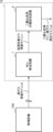
- FIG. 1 is a schematic diagram of an acidic gas separation and recovery system according to a first embodiment.
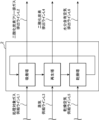
- FIG. 2 is a schematic diagram of an example of the configuration of a carbon dioxide separation and capture facility in the first embodiment.
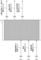
- FIG. 3 is a schematic diagram of another example of the configuration of the carbon dioxide separation and capture facility in the first embodiment.
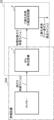
- FIG. 4 is a schematic diagram of an acidic gas separation and recovery system according to the second embodiment.
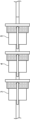
- FIG. 5 is a schematic diagram for explaining a mechanism for collecting trace components in a gas by solid-phase extraction in the embodiment.
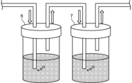
- FIG. 6 is a schematic diagram for explaining the mechanism of collecting trace components in a gas by the liquid phase extraction method in the embodiment.
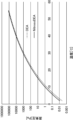
- FIG. 7 is a graph showing the vapor pressure curves of diethanolamine and NDEA in the examples.
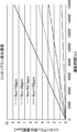
- FIG. 8 is a graph of nitrosamine emission concentrations when the NOx concentration is set to 10 ppm, 40 ppm, 63.7 ppm, or 150 ppm.
- an exhaust gas treatment device that further includes a denitrification device as a pretreatment device to suppress deterioration of the amine absorbing solution can also suppress the emission of nitrosamines to the outside of the system (see Patent Document 1).
- a carbon dioxide separation and capture process using a solid absorbent differs from a process using an amine absorbing solution in that the solid absorbent itself has a low water content. Therefore, it is difficult to predict whether strong acids (nitric acid and nitrous acid) will be generated by a mechanism similar to that of the amine absorbing solution method described above, and further whether nitrosamines will be generated by reaction with strong acids.
- strong acids nitric acid and nitrous acid
- the inventors verified whether compounds that affect the surrounding environment are emitted into the gas discharged from a carbon dioxide separation and capture facility using a solid absorbent. As a result, they detected and identified two types of nitrosamines that were produced by an unclear mechanism and were contained in the exhaust gas.
- an acid gas separation and recovery system and method capable of suppressing the amount of nitrosamines that diffuse onto the ground and separating and recovering carbon dioxide, which is environmentally favorable.
- exhaust gas is not particularly limited as long as it contains carbon dioxide and NOx.
- gases discharged from combustion equipment such as thermal power plants that use coal, heavy oil, natural gas, etc. as fuel, blast furnaces in steelworks that reduce iron oxide with coke, converters in steelworks that burn carbon in pig iron to make steel, and boilers in various manufacturing plants, and gases discharged from transportation equipment such as automobiles, ships, and aircraft that use gasoline, heavy oil, light oil, etc. as fuel.
- NOx refers to oxides of nitrogen that are produced when a substance burns at high temperatures, and examples of such oxides include NO, NO2 , N2O , and N2O3 .
- gas to be treated means gas from which at least NOx has been partially or completely removed from exhaust gas, the NOx concentration in the gas to be treated is 63.7 ppm or less, and which is to be treated in a carbon dioxide separation and capture process using a solid absorbent.
- the carbon dioxide content and temperature in the gas to be treated so long as the conditions are such that the gas to be treated can absorb carbon dioxide when it comes into contact with the solid absorbent.
- the carbon dioxide partial pressure may be 1 kPa or more, and the temperature may be 20°C to 60°C.
- exhaust gas refers to gas that may contain trace amounts of nitrosamines and is discharged from the exhaust line (chimney, flue, etc.) of the carbon dioxide separation and capture equipment after adsorption and desorption of the carbon dioxide contained in the gas to be treated. The exhaust gas then diffuses into the atmosphere and reaches the ground.
- Fig. 1 shows a schematic diagram of an acidic gas separation and recovery system in embodiment 1.
- the acidic gas separation and recovery system 10 includes a NOx removal facility 1 and a carbon dioxide separation and recovery facility 2 that adsorbs and desorbs carbon dioxide using a solid absorbent material.
- the NOx removal equipment 1 removes NOx from exhaust gas emitted from combustion equipment 10A such as a power plant, a blast furnace, or a boiler.
- the exhaust gas is supplied from the combustion equipment 10A to the NOx removal equipment 1 through an exhaust gas supply line L0.
- the NOx removal equipment 1 reduces the NOx concentration in the gas to be treated, which is supplied to the carbon dioxide separation and capture equipment 2 installed downstream of the NOx removal equipment 1, to 63.7 ppm or less. If the NOx concentration in the gas to be treated is 63.7 ppm or less, the amount of nitrosamines diffused to the ground from the carbon dioxide separation and capture equipment 2 described later during the approximate average regular repair period of the carbon dioxide separation and capture equipment (specifically, about one year (operation period of about 8000 hours)) can be suppressed to an extremely small amount.
- the maximum landing concentration of nitrosamines on the ground after diffusion (hereinafter also simply referred to as "maximum landing concentration of nitrosamines”) can be reduced to 1 ⁇ g/m 3 or less (0.167 ppb or less in terms of the molar composition of N-nitrosodiethanolamine).
- maximum landing concentration of nitrosamines can be reduced to 1 ⁇ g/m 3 or less (0.167 ppb or less in terms of the molar composition of N-nitrosodiethanolamine).
- the NOx concentration in the gas to be treated that is supplied to the carbon dioxide separation and capture equipment 2 is preferably 60 ppm or less, more preferably 55 ppm or less, even more preferably 50 ppm or less, particularly preferably 47 ppm or less, and even more preferably 45 ppm or less, in order to more strictly consider the risk of nitrosamines diffusing to the ground.
- this NOx concentration is a concentration assuming that the nitrosamines diffusing to the ground are N-nitrosodiethanolamines (hereinafter also referred to as "NDEA").
- NDEA N-nitrosodiethanolamines
- the maximum allowable NOx concentration in such gas to be treated may be adjusted appropriately depending on the volatility of the nitrosamines generated. Furthermore, the replacement period of the solid absorbent material varies depending on the type of combustion equipment to which the carbon dioxide separation and capture equipment is attached. Therefore, the maximum allowable NOx concentration in such gas to be treated may also be adjusted appropriately depending on the type of combustion equipment.
- NOx concentration in gas
- chemiluminescence method as specified in JIS B 7953:2004 "Automatic measuring device for nitrogen oxides in the atmosphere.”
- Such NOx removal equipment 1 is not particularly limited as long as it is any denitrification equipment known to those skilled in the art.
- the NOx removal equipment 1 may be equipment that removes NOx in the exhaust gas using a solid absorbent material in which an amine is supported on a porous substrate, similar to the carbon dioxide separation and capture equipment 2 described below.
- the NOx removal equipment 1 is equipment that uses such a solid absorbent material, the NOx concentration in the gas to be treated can be easily reduced to the extremely low concentration described above.
- the type of amine used in the solid absorbent of the carbon dioxide separation and capture equipment 2 described below is the same as the type of amine used in the solid absorbent of the NOx removal equipment 1.
- the same type of amine it is possible to prevent a type of amine different from the amine used in the carbon dioxide separation and capture equipment 2 from entering from the NOx removal equipment 1 and having any effect on the adsorption and desorption of carbon dioxide.
- the solid absorbent used in the NOx removal equipment 1 includes a solid absorbent used to adsorb and desorb carbon dioxide in the carbon dioxide separation and capture equipment 2 described later.
- the solid absorbent for the NOx removal equipment 1 includes a solid absorbent used to adsorb and desorb carbon dioxide in the carbon dioxide separation and capture equipment 2 described later.
- NOx has a stronger bond with amines than carbon dioxide. Therefore, even if a solid absorbent that has already been used for a certain period of time (for example, about one to three years, which is the general replacement period) for carbon dioxide separation and capture is used, a sufficient amount of NOx can be removed. In this way, by reusing the solid absorbent in the NOx removal equipment 1, an acid gas separation and capture system 10 that is environmentally friendly can be realized at low cost.
- the NOx removal equipment 1 may be a general denitration device that applies any method known to those skilled in the art. Examples of such NOx removal equipment 1 include denitration devices that apply ammonia selective catalytic reduction, flue gas denitration, non-catalytic selective reduction, etc.
- the carbon dioxide separation and capture equipment 2 is installed downstream of the gas flow of the NOx removal equipment 1, and the gas to be treated is supplied from the NOx removal equipment 1 through the gas to be treated supply line L1.
- the carbon dioxide separation and capture equipment 2 then separates and captures the carbon dioxide in the gas to be treated.
- the exhaust gas after separation and capture is discharged as carbon dioxide-free exhaust gas through the carbon dioxide-free exhaust gas discharge line L2.
- the carbon dioxide in the gas to be treated is captured (not shown).
- the carbon dioxide separation and capture equipment 2 may be of any configuration as long as it is capable of adsorbing and desorbing carbon dioxide contained in the gas to be treated using a solid absorbent material in which an amine is supported on a porous substrate.
- the configuration of such a carbon dioxide separation and capture equipment 2 is not particularly limited, but examples include the following configurations.
- FIG. 2 shows a schematic diagram of an example of the configuration of the carbon dioxide separation and capture equipment in embodiment 1.
- the carbon dioxide separation and capture equipment 2 in FIG. 2 is a moving bed type carbon dioxide separation and capture equipment 2 in which the solid absorbent is transported in the order of the adsorption tower, regeneration tower, and drying tower.
- the solid adsorbent is returned from the drying tower to the adsorption tower by a conveyor or the like. Note that the configurations of the adsorption tower, regeneration tower, and drying tower may be changed as appropriate from the configuration shown in FIG. 2.
- the gas to be treated supplied through the gas to be treated supply line L1 comes into contact with the solid absorbent packed in the adsorption tower.
- the carbon dioxide in the gas to be treated is adsorbed and removed by the solid absorbent. Therefore, the carbon dioxide-free exhaust gas from which the carbon dioxide has been removed is discharged from the adsorption tower through the carbon dioxide-free exhaust gas discharge line L2. After carbon dioxide adsorption, the solid absorbent is transferred to the regeneration tower.
- the transferred solid absorbent after carbon dioxide adsorption comes into contact with steam supplied through the steam supply line L3.
- the temperature of the steam is not particularly limited, but is, for example, 60°C or higher.
- carbon dioxide is desorbed from the solid absorbent, and carbon dioxide gas is discharged from the regeneration tower through the carbon dioxide discharge line L4.
- the solid absorbent with the steam attached is transferred to the drying tower.
- the solid absorbent material with the transported steam attached to it comes into contact with dry air supplied through the dry air supply line L5.
- moisture and other substances attached to the solid absorbent material evaporate, and the water vapor and dry gas resulting from the evaporation are discharged through the moisture-containing air discharge line L6.
- the solid absorbent material is returned to the adsorption tower.
- FIG. 3 shows a schematic diagram of another example of the configuration of the carbon dioxide separation and capture equipment in embodiment 1.
- one tank filled with a solid absorbent material functions as the adsorption tower, regeneration tower, and drying tower described above for the absorption process, regeneration process, and drying process, respectively. These three processes of the absorption process, regeneration process, and drying process are then repeated periodically.
- the carbon dioxide separation and capture equipment 2 in FIG. 3 is a fixed-bed type carbon dioxide separation and capture equipment.
- supply lines are configured so that the gas to be treated, steam and dry air can each be supplied to the tank of the carbon dioxide separation and capture equipment 2 from the gas to be treated supply line L1, the steam supply line L3 and the dry air supply line L5, respectively.
- exhaust lines are configured so that the carbon dioxide-free exhaust gas, carbon dioxide and moisture-containing air can each be discharged from the carbon dioxide-free exhaust gas exhaust line L2, the carbon dioxide exhaust line L4 and the moisture-containing air exhaust line L6, respectively.
- each of these supply lines and exhaust lines is provided with an on-off valve.
- the gas to be treated is supplied to the tank through the gas to be treated supply line L1 and comes into contact with the solid absorbent filled in the tank.
- the carbon dioxide in the gas to be treated is adsorbed by the solid absorbent. Therefore, the carbon dioxide-free exhaust gas from which the carbon dioxide has been removed is discharged through the carbon dioxide-free exhaust gas discharge line L2.
- the opening and closing valves other than those on the gas to be treated supply line L1 and the carbon dioxide-free exhaust gas discharge line L2 are closed.
- the type of porous substrate is not particularly limited.
- the porous substrate can be made of any material known to those skilled in the art that can support the amine described below and has a large number of pores that can adsorb and desorb carbon dioxide.
- porous substrates include silica, such as silica gel or mesoporous silica, alumina, such as activated alumina, zeolite, titania, zirconia, magnesia, activated carbon, metal organic frameworks (MOFs), etc. If these materials are in powder form, they may be granulated using an appropriate binder and used as the porous substrate.
- silica such as silica gel or mesoporous silica
- alumina such as activated alumina, zeolite, titania, zirconia, magnesia, activated carbon, metal organic frameworks (MOFs), etc. If these materials are in powder form, they may be granulated using an appropriate binder and used as the porous substrate.
- the type of amine is not particularly limited, and any amine or polyamine that can be supported on any porous substrate known to those skilled in the art and that can adsorb and desorb carbon dioxide can be used.
- Examples of the types of amine include monoethanolamine, diethanolamine, triethanolamine, polyethyleneimine, ethylenediamine, diethylenetriamine, triethylenetetramine, tetraethylenepentamine, pentaethylenehexamine, etc.
- One type of amine may be used, or two or more types of amines may be used in combination.
- the method for producing the solid absorbent is not particularly limited, but it can be produced, for example, by the following method.
- the amine is dissolved in a solvent to prepare an amine absorbent solution.
- concentration of the amine in the amine absorbent solution is not particularly limited, but may be adjusted to an appropriate value in the range of 5% by mass to 70% by mass depending on the type of amine used.
- the porous substrate e.g., the aforementioned porous particles
- the amine absorbent solution is impregnated into the porous substrate.
- the immersion time is not particularly limited as long as it is a time that allows the inside of the pores to be sufficiently degassed.
- the immersion time can be 24 hours.
- porous substrate is lifted out of the amine absorbent solution, and excess liquid adhering to it is removed by suction filtration or other methods.
- the porous substrate is then aerated or dried under reduced pressure at a temperature close to room temperature, yielding a solid absorbent.
- the NOx concentration in the gas to be treated is 63.7 ppm or less. Therefore, the amount of nitrosamines generated by the reaction between NOx and amines in the carbon dioxide separation and recovery equipment 2 can be suppressed to a small amount during the approximate average regular repair period of the carbon dioxide separation and recovery equipment (specifically, about one year (operation period of about 8000 hours)). Therefore, the acidic gas separation and recovery system 10 can suppress the amount of nitrosamines diffused to the ground to an extremely small amount (specifically, the maximum landing concentration of nitrosamines can be reduced to 1 ⁇ g/m 3 or less), which is environmentally favorable and can efficiently separate and capture carbon dioxide.
- carbon dioxide separation and capture methods using solid absorbents can desorb carbon dioxide from solid absorbents using exhaust heat that generally cannot be effectively utilized. Therefore, from this perspective as well, they are favorable from an environmental perspective.
- Fig. 4 shows a schematic diagram of an acidic gas separation and recovery system in embodiment 2.
- the acidic gas separation and recovery system 20 includes a NOx removal facility 1 installed in a combustion facility 20A, and a carbon dioxide separation and recovery facility 2 that adsorbs and desorbs carbon dioxide using a solid absorbent material.
- an acid gas separation and capture system 10 was described in which the NOx removal equipment 1 is installed downstream of the gas flow of the combustion equipment 10A and upstream of the gas flow of the carbon dioxide separation and capture equipment 2.
- the acidic gas separation and recovery system 20 in the second embodiment differs from the acidic gas separation and recovery system 10 in the first embodiment in that, as shown in FIG. 4, a denitration device already installed in a general combustion facility 20A such as a power plant, a blast furnace, or a boiler has the same function as the NOx removal facility 1 described above.
- the acidic gas separation and recovery system 20 is configured to enhance the denitration effect of a denitration device already installed in the general combustion facility 20A, so that the NOx concentration in the gas to be treated supplied to the carbon dioxide separation and recovery facility 2 is 63.7 ppm or less.
- the acidic gas separation and capture system 20 in this embodiment 2 can suppress the amount of nitrosamines generated by the reaction between NOx and amines in the carbon dioxide separation and capture equipment 2 to a small amount during the approximate average regular maintenance period of the carbon dioxide separation and capture equipment (specifically, about one year (operating period of about 8,000 hours)). Therefore, the acidic gas separation and capture system 20 can also suppress the amount of nitrosamines diffused to the ground to an extremely small amount (specifically, the maximum ground landing concentration of nitrosamines can be reduced to 1 ⁇ g/m3 or less ), which is environmentally favorable and can efficiently separate and capture carbon dioxide.
- the modified acid gas separation and recovery system includes a NOx removal facility and a carbon dioxide separation and recovery facility that adsorbs and desorbs carbon dioxide using a solid absorbent, similar to the acid gas separation and recovery system in the above-described embodiment 1 or 2.
- the details of the configurations of the NOx removal facility and the carbon dioxide separation and recovery facility are similar to those of the above-described embodiment 1 or 2.
- the NOx concentration in the gas to be treated is 63.7 ppm or less, but this modified example differs in that the NOx concentration in the gas to be treated is set to a specific concentration or less.
- the specific concentration is a concentration that can maintain a value that keeps the maximum landing concentration of nitrosamines after the exhaust gas emitted from the carbon dioxide separation and capture equipment diffuses below a preset regulatory value.
- the period for which such a value is maintained is preferably the period of scheduled repairs of the carbon dioxide separation and capture equipment.
- the "maximum landing concentration of nitrosamines (on the ground) after diffusion” refers to the concentration of nitrosamines at a ground point estimated to have the smallest dilution rate, calculated from the values of the exhaust gas volume, gas temperature, stack height, atmospheric stability, effective stack height, and diffusion parameters consisting of the evaluation time, P-G diagram evaluation time, and power exponent of the horizontal diffusion width, when a plant such as an arbitrary coal-fired power plant is used as a model case, as will be described in detail in the Examples below. Furthermore, in this specification, the maximum landing concentration of nitrosamines is taken to be the largest concentration among the concentrations estimated using the weak wind puff method, the puff method, and the plume method.
- the "pre-set regulation value” may be set arbitrarily depending on the surrounding work environment on the ground. For example, in places with precious natural environments or where many people live nearby, it is better to set the regulation value as low as possible. Also, in places with almost no nature nearby or where few people live nearby, the regulation value may be set to a normal value.
- This modified acid gas separation and recovery system can reduce the amount of nitrosamines that diffuse onto the ground to an amount appropriate for the surrounding environment, making it environmentally friendly, while also allowing for efficient separation and recovery of carbon dioxide.
- the NOx concentration in the gas to be treated may be set to a concentration that allows the maximum ground concentration of nitrosamines to be maintained at 1 ⁇ g/m3 or less (or 0.167 ppb or less in terms of the molar composition of NDEA) until the operation time of the carbon dioxide separation and capture equipment reaches 8000 hours.
- the amount of nitrosamines diffusing to the ground can be suppressed to a very small amount, which is environmentally friendly and allows carbon dioxide to be separated and captured efficiently.
- the acidic gas separation and recovery method in this embodiment includes removing NOx and separating and recovering carbon dioxide.
- the NOx in the exhaust gas is removed, and the NOx concentration in the gas to be treated after NOx removal is set to 63.7 ppm or less.
- the preferred upper limit of the NOx concentration in the gas to be treated is the same as the value described in the acidic gas separation and recovery system according to the first aspect. Note that the maximum value of the NOx concentration in the gas to be treated can also be appropriately adjusted depending on the type of combustion equipment that emits the exhaust gas to which the acidic gas separation and recovery method of this embodiment is applied.
- the solid absorbent includes a solid absorbent used to adsorb and desorb carbon dioxide when separating and recovering carbon dioxide, as in the acid gas separation and recovery system according to the first aspect described above.
- the acid gas separation and recovery system according to the first aspect described above any denitrification equipment, device, denitrification method, etc. known to those skilled in the art may be applied in removing NOx.
- a solid absorbent material in which an amine is supported on a porous substrate is used to adsorb and desorb the carbon dioxide contained in the gas to be treated.
- any equipment e.g., moving bed or fixed bed type carbon dioxide separation and recovery equipment
- device, method, etc. known to those skilled in the art that is capable of adsorbing and desorbing the carbon dioxide contained in the gas to be treated using a solid absorbent may be used.
- the amount of nitrosamines generated by the reaction between NOx and amines when separating and capturing carbon dioxide can be kept to a small amount during an approximate average regular repair period of the carbon dioxide separation and capture equipment (specifically, about one year (operating period of about 8,000 hours)). Therefore, the acid gas separation and recovery method of this embodiment is environmentally friendly because it can suppress the amount of nitrosamines diffused to the ground to an extremely small amount (specifically, it can reduce the maximum landing concentration of nitrosamines to 1 ⁇ g/m3 or less), and can separate and capture carbon dioxide efficiently.
- the modified acidic gas separation and recovery method includes removing NOx, and using a solid absorbent to adsorb and desorb carbon dioxide contained in the gas to be treated after the NOx removal, and separating and recovering the carbon dioxide, as in the acidic gas separation and recovery method in the above-described embodiment.
- the details of the removal of NOx and the separation and recovery of carbon dioxide are the same as those in the above-described embodiment.
- the NOx concentration in the gas to be treated was 63.7 ppm or less, but this modified example differs in that the NOx concentration in the gas to be treated is set to a specific concentration or less.
- the specific concentration is a concentration that allows the maximum landing concentration of nitrosamines after diffusion in the exhaust gas emitted after carbon dioxide separation and capture to be maintained at a value that is equal to or less than a preset regulatory value.
- the period during which such a value is maintained is preferably the period of regular maintenance of the equipment used to separate and capture carbon dioxide.
- the meanings of "maximum landing concentration of nitrosamines after diffusion" and "preset regulatory value" are as described above.
- This modified acid gas separation and recovery method can reduce the amount of nitrosamines that diffuse onto the ground to an amount appropriate for the surrounding environment, making it environmentally friendly, while also allowing for efficient separation and recovery of carbon dioxide.
- the NOx concentration in the gas to be treated may be set to a concentration at which the maximum landing concentration of nitrosamines can be maintained at 1 ⁇ g/ m3 or less (or 0.167 ppb or less in terms of the molar composition of NDEA) until the total time for separating and capturing carbon dioxide (i.e., the operation time of the carbon dioxide separation and capture equipment, etc.) reaches 8000 hours.
- the amount of nitrosamines diffusing to the ground can be suppressed to a very small amount, which is environmentally friendly and allows carbon dioxide to be separated and captured efficiently.
- the acid gas separation and recovery system includes a NOx removal facility for removing NOx from an exhaust gas, and a carbon dioxide separation and capture facility that is installed downstream of the gas flow of the NOx removal facility and that adsorbs and desorbs carbon dioxide contained in the gas to be treated that is supplied from the NOx removal facility using a solid absorbent material having an amine supported on a porous substrate,
- the NOx concentration in the gas to be treated supplied from the NOx removal facility to the carbon dioxide separation and capture facility is 63.7 ppm or less.
- the first aspect of the acid gas separation and recovery system can suppress the amount of nitrosamines that diffuse onto the ground, and can provide an acid gas separation and recovery system that can separate and recover carbon dioxide, which is environmentally friendly.
- the second aspect of the acid gas separation and recovery system of the present disclosure is the acid gas separation and recovery system of the first aspect, in which the NOx removal equipment removes NOx from the exhaust gas using a solid absorbent material in which an amine is supported on a porous substrate.
- the second embodiment of the acid gas separation and recovery system can easily reduce the NOx concentration in the gas to be treated to an extremely low concentration.
- the third aspect of the acid gas separation and recovery system of the present disclosure is the acid gas separation and recovery system of the second aspect, in which the solid absorbent material used in the NOx removal equipment includes the solid absorbent material used to adsorb and desorb carbon dioxide in the carbon dioxide separation and recovery equipment.
- the third aspect of the acid gas separation and recovery system allows the solid absorbent to be reused, making it possible to realize an environmentally friendly acid gas separation and recovery system at low cost.
- the acid gas separation and recovery method includes removing NOx from an exhaust gas; and using a solid absorbent material having an amine supported on a porous substrate, adsorbing and desorbing carbon dioxide contained in the gas to be treated after the NOx removal, and separating and recovering the carbon dioxide.
- the NOx concentration in the gas to be treated after the NOx removal is 63.7 ppm or less.
- the fourth aspect of the acid gas separation and recovery method can suppress the amount of nitrosamines that diffuse to the ground, and can provide an acid gas separation and recovery method that can separate and recover carbon dioxide, which is environmentally favorable.
- the fifth aspect of the present disclosure is the fourth aspect of the acid gas separation and recovery method, in which NOx is removed from the exhaust gas using a solid absorbent material in which an amine is supported on a porous substrate.
- the fifth aspect of the acid gas separation and recovery method makes it easy to reduce the NOx concentration in the gas to be treated to an extremely low concentration.
- the sixth aspect of the present disclosure is the acid gas separation and recovery method of the fifth aspect, in which the solid absorbent material used in removing NOx includes a solid absorbent material used to adsorb and desorb carbon dioxide when separating and recovering the carbon dioxide.
- the sixth aspect of the acid gas separation and recovery method allows the solid absorbent to be reused, making it possible to realize an environmentally friendly acid gas separation and recovery method at low cost.
- a seventh aspect of the present disclosure provides an acid gas separation and recovery system, comprising: a NOx removal facility for removing NOx in exhaust gas; and a carbon dioxide separation and capture facility that is installed downstream of the gas flow of the NOx removal facility and that adsorbs and desorbs carbon dioxide contained in the gas to be treated that is supplied from the NOx removal facility using a solid absorbent material having an amine supported on a porous substrate,
- the NOx concentration in the gas to be treated supplied from the NOx removal equipment to the carbon dioxide separation and capture equipment is set to a concentration that maintains the maximum landing concentration of nitrosamines after diffusion of the exhaust gas discharged from the carbon dioxide separation and capture equipment at a value that is below a predetermined regulatory value.
- the seventh aspect of the acid gas separation and recovery system can reduce the amount of nitrosamines that diffuse onto the ground to an amount appropriate for the surrounding environment, providing an acid gas separation and recovery system capable of separating and recovering carbon dioxide, which is environmentally favorable.
- An acidic gas separation and recovery system is the acidic gas separation and recovery system according to the seventh aspect, wherein the NOx concentration in the gas to be treated is set to a concentration that allows the maximum landing concentration of nitrosamines after diffusion of the exhaust gas to be maintained at 1 ⁇ g/m3 or less until the operating time of the carbon dioxide separation and recovery equipment reaches 8,000 hours.
- the eighth aspect of the acid gas separation and recovery system can suppress the amount of nitrosamines that diffuse onto the ground, and can provide an acid gas separation and recovery system that can separate and recover carbon dioxide, which is environmentally friendly.
- a ninth aspect of the present disclosure provides a method for separating and recovering acidic gas, comprising removing NOx from an exhaust gas; and using a solid absorbent material having an amine supported on a porous substrate, adsorbing and desorbing carbon dioxide contained in the gas to be treated after NOx removal, and separating and recovering the carbon dioxide.
- the NOx concentration in the gas to be treated after the NOx removal is set to a concentration that maintains the maximum landing concentration of nitrosamines after diffusion of the exhaust gas discharged after the separation and recovery of the carbon dioxide at or below a predetermined regulatory value.
- the ninth aspect of the acid gas separation and recovery method can suppress the amount of nitrosamines diffusing onto the ground to an amount suitable for the surrounding environment, providing an acid gas separation and recovery method capable of separating and recovering carbon dioxide, which is environmentally favorable.
- An acidic gas separation and recovery method is the acidic gas separation and recovery method according to the ninth aspect, wherein the NOx concentration in the gas to be treated is set to a concentration that allows a maximum landing concentration of nitrosamines after diffusion of the exhaust gas to be maintained at 1 ⁇ g/m3 or less until a total time for separating and recovering carbon dioxide reaches 8,000 hours.
- the acid gas separation and recovery method of the tenth aspect can suppress the amount of nitrosamines that diffuse to the ground, and can provide an acid gas separation and recovery method that can separate and recover carbon dioxide, which is environmentally favorable.
- the upper limit of the NOx concentration (ppm) in the gas to be treated and supplied to the carbon dioxide capture and separation facility was calculated to suppress the amount of nitrosamines diffusing to the ground to a small amount (specifically, an amount that results in a maximum ground concentration of nitrosamines of 1 ⁇ g/m 3 or less) during the approximate average regular maintenance period of the carbon dioxide capture and separation facility (specifically, about one year (operation period of about 8000 hours)). This will be described in detail below.
- Detection and Identification of Nitrosamines For the detection of nitrosamines in gas, the carbon dioxide capture equipment and experimental exhaust gas described below were used. Furthermore, using these, nitrosamines were detected and identified by a method for collecting trace components in the gas discharged from the carbon dioxide capture equipment and a method for detecting and identifying the molecular species of the collected components, described below. In addition, the detected and identified nitrosamines were discussed.
- the exhaust gas supply line (L0) is the exhaust gas supply line (L0). Specifically, in the absorption process, the exhaust gas is supplied to the tank through the exhaust gas supply line (L0), comes into contact with the solid absorbent filled in the tank, and the carbon dioxide in the exhaust gas is adsorbed by the solid absorbent.
- the solid absorbent filled in the tank was manufactured by the following method. Specifically, first, silica gel with a particle diameter of 1 mm to 5 mm, which is a porous substrate, was immersed in an aqueous diethanolamine solution. The immersed silica gel was left at room temperature for 8 hours or more. After leaving it, the silica gel was removed, the excess diethanolamine aqueous solution attached to the silica gel was separated, and dry gas (nitrogen gas at 40°C and 15 L/min) was passed through it to dry it by aeration (see the manufacturing method of solid absorbent described in Japanese Patent No. 6055134). The drying end condition for the silica gel carrying diethanolamine (i.e., the solid absorbent) was set to 2 hours after the gas temperature at the outlet of the drying tank for drying the silica gel carrying diethanolamine became stable.
- the experimental exhaust gas supplied through the exhaust gas supply line was a simulated exhaust gas made by mixing air and high-purity carbon dioxide, to which 30 ppm of NOx was further added.
- Figure 5 shows a schematic diagram for explaining the mechanism for collecting trace components in gas by solid-phase extraction.
- a first cartridge 3 filled with a copolymer, a second cartridge 4 filled with a strong cation exchange resin, and a third cartridge 5 filled with activated carbon are arranged in series, and gas from the three gas outlets is passed in the direction shown by the arrow in Figure 5.
- gas from the three gas outlets By passing gas from the three gas outlets through these three cartridges, all trace components of acidic, basic, and neutral molecules in the gas can be sorbed and collected.
- Figure 6 shows a schematic diagram to explain the mechanism for collecting trace components in gas using liquid-phase extraction.
- a first impinger 6 holding a 0.1% sulfamic acid solution is placed in the front stage close to the gas flow from the gas exhaust port.
- a second impinger 7 holding ultrapure water is placed in the rear stage far from the gas flow from the gas exhaust port so as to be in series with the first impinger 6.
- gas from the three gas exhaust ports is passed through the first impinger 6 and second impinger 7 placed in series in this way in the direction shown by the arrows in Figure 6 to collect trace components in the gas.
- HLB refers to the first cartridge 3 filled with a copolymer
- MC-1 refers to the second cartridge 4 filled with a strong cation exchange resin
- AC2 refers to the third cartridge 5 filled with activated carbon.
- nitrosamines detected and identified As shown in Tables 1 to 6 above, in addition to diethanolamine actually supported on the solid absorbent, various components were detected in the gas from the three gas exhaust ports of the carbon dioxide separation and capture equipment. As shown in Tables 5 and 6, the detected components also included nitrosamines N-nitrosodibutylamine (No. 29) and NDEA (No. 30). From these detection results, it was found that when exhaust gas containing NOx is supplied to a carbon dioxide separation and capture equipment using a solid absorbent, the amine supported on the solid absorbent reacts with NOx, and nitrosamines are contained in the gas discharged from the gas exhaust port. Therefore, when a general exhaust gas having a NOx concentration exceeding 100 ppm is treated by a carbon dioxide separation and capture process using a solid absorbent, these generated nitrosamines may diffuse to the ground and pollute the surrounding environment.
- NDEA NDEA
- the mechanism of nitrosation has also been clarified.
- the main component of the nitrosated product in this detection result is N-nitrosodibutylamine (No. 29).
- the detected concentration of N-nitrosodibutylamine (No. 29) was about 30 times that of NDEA (No. 30), the main nitrosated product of diethanolamine.
- the results of cartridge collection showed that the detected concentration of N-nitrosodibutylamine (No. 29) was 781,499,956, and the detected concentration of NDEA was 28,733,260.
- the results of impinger collection showed that the detected concentration of NDEA was 0. Therefore, the nitrosation mechanism in this detection result is an unclear mechanism that could not be predicted at all from conventional technology. From these observations, it is clear that the generation of nitrosamines in a carbon dioxide separation and capture process using a solid absorbent is not self-evident from the simple nitrosamine generation mechanism in a carbon dioxide separation and capture process using an amine absorption liquid method.
- the upper limit of the NOx concentration in the gas to be treated supplied to the carbon dioxide capture equipment in order to suppress the amount of nitrosamines diffusing to the ground to a small amount
- the upper limit of the NOx concentration in the gas to be treated that can suppress the amount of nitrosamines diffusing to the ground to a small amount (specifically, an amount that results in a maximum ground landing concentration of nitrosamines of 1 ⁇ g/ m3 or less) during an approximate average regular repair period of the carbon dioxide capture equipment (specifically, about one year (operating period of about 8,000 hours)) was calculated using the following method.
- Nitrosamines are not contained in the solid absorbent in the carbon dioxide capture equipment immediately after it is put into use. When exhaust gas containing NOx is supplied to the carbon dioxide capture equipment, NOx reacts with diethanolamine, and nitrosamines gradually accumulate in the equipment. As the accumulated concentration of nitrosamines increases, the volatilized concentration of nitrosamines also increases.
- the NOx concentration in the exhaust gas supplied to the carbon dioxide capture equipment is calculated so that the exhaust gas from the exhaust line (chimney, flue, etc.) of the carbon dioxide capture equipment diffuses into the atmosphere and the maximum landing concentration of nitrosamines (more specifically, NDEA) does not exceed the regulated value until 8,000 hours after the start of operation.
- This method for calculating the upper limit of NOx concentration has the following three calculation steps.
- the exhaust gas flow rate in the above formula can be determined by the carbon dioxide concentration in the exhaust gas supplied to the carbon dioxide capture facility, the target carbon dioxide capture rate, and the performance of the solid absorbent.
- the following values were set as conditions for a typical coal combustion exhaust gas carbon dioxide capture facility.
- Carbon dioxide concentration in exhaust gas 15%
- Carbon dioxide recovery rate 90%
- the performance of the solid absorbent used in the carbon dioxide separation and capture facility was set as follows, based on representative literature on solid absorbents such as diethanolamine. -Type of amine supported on solid absorbent: diethanolamine -Amount of amine supported on solid absorbent: 36 wt% (see Micropor. Mesopor. Mater. 226, p444-453 (2016)) ⁇ Carbon dioxide absorption: 2.85 wt% (see Micropor. Mesopor. Mater. 226, p444-453 (2016)) Carbon dioxide absorption time: 30 minutes (set based on the 22 minutes in Micropor. Mesopor. Mater. 226, p.
- Regeneration time of solid absorbent 2.5 hours (set based on the ratio of absorption and desorption times (6 times) calculated from Micropor. Mesopor. Mater. 62, p. 29-45 (2003))
- Substrate bulk density 400 kg/m 3 (see catalog value for spherical silica gel manufactured by Kanto Chemical Co., Ltd.)
- Absorbent bulk density 625 kg/m 3 (calculated from the bulk density of the substrate and the amount of amine supported)
- An example of a carbon dioxide separation and capture system in which the carbon dioxide absorption time is 30 minutes and the solid absorbent regeneration time is 2.5 hours is a carbon dioxide separation and capture system having five tanks (or towers) as shown in Figure 3, in which exhaust gas is supplied to one of the tanks (or towers) of the carbon dioxide separation and capture system while the solid absorbent regeneration process and drying process are carried out in the remaining four tanks (or towers).
- the solid absorbent of the carbon dioxide separation and capture equipment supports a specific amount of diethanolamine at 100% purity.
- the amount of diethanolamine decreases due to volatilization, and the amount of diethanolamine supported also decreases due to nitrosation (i.e., the production of nitrosamines) caused by reaction with NOx in the exhaust gas.
- the volatilization and nitrosation behavior was simulated as follows. i) Based on Raoult's law, the vapor pressure of each compound in the mixture of diethanolamine and nitrosamine supported on the solid absorbent was calculated. Note that the calculation results of the vapor pressure were used for the calculations from ii) onwards, since the amount of volatilization depends on the vapor pressure. ii) The amounts of diethanolamine and nitrosamine that volatilized and the amount of diethanolamine that was converted to nitrosamine during a short time period ⁇ t were calculated.
- the outlet gas temperature of the absorption process was set to 45°C.
- the vapor pressure of diethanolamine was calculated using the Antoine parameters described in Klepacova et al., J. Chem. Eng. Data, 2011, 56, pp. 2242-248.
- the vapor pressure of nitrosamine (specifically, NDEA) was calculated by determining the Antoine parameters that reproduce the estimated values at 0°C, 20°C, and 40°C described in R. G. Klein, Toxicology, 23, pp. 135-147 (1982) by fitting using the least squares method.
- Figure 7 shows the vapor pressure curves of diethanolamine and NDEA in the examples.
- Figure 8 shows a graph of the nitrosamine emission concentration when the NOx concentration was set to 10 ppm, 40 ppm, 63.7 ppm, or 150 ppm.
- the location showing the maximum ground concentration was 2876 m from the chimney, and the dilution ratio at that location was estimated to be 7.29 ⁇ 10 -5 .
- the evaluation time was set to 60 minutes
- the P-G diagram evaluation time was set to 3 minutes
- the power exponent of the horizontal diffusion width was set to 0.2.
- maximum ground concentration was also estimated using the weak wind puff method under weak wind conditions and the puff method under no wind conditions.
- the maximum ground concentration estimated using the plume method was the highest, the evaluation results using the plume method were used in order to more strictly consider the risk of nitrosamines being dispersed to the ground.
- the upper limit of the nitrosamine emission concentration in the exhaust gas discharged from the exhaust line (chimney, flue, etc.) of the carbon dioxide separation and capture facility corresponding to the regulation value of the concentration on the ground can be set to 2.29 ppm. Furthermore, based on the graph of the nitrosamine emission concentration when the NOx concentration obtained in 1) above is varied, it can be confirmed that the NOx concentration in the exhaust gas that prevents the nitrosamine emission concentration in the exhaust gas from exceeding the upper limit of 2.29 ppm up to 8,000 hours is 63.7 ppm or less.
Landscapes
- Chemical & Material Sciences (AREA)
- Engineering & Computer Science (AREA)
- Analytical Chemistry (AREA)
- General Chemical & Material Sciences (AREA)
- Oil, Petroleum & Natural Gas (AREA)
- Chemical Kinetics & Catalysis (AREA)
- Environmental & Geological Engineering (AREA)
- Health & Medical Sciences (AREA)
- Biomedical Technology (AREA)
- Treating Waste Gases (AREA)
- Gas Separation By Absorption (AREA)
Abstract
Description
前記NOx除去設備のガス流れの後流側に設置されており、かつ、多孔質基材にアミンを担持させた固体吸収材を用いて前記NOx除去設備から供給される処理対象ガス中に含有される二酸化炭素を吸着および脱着する二酸化炭素分離回収設備と、を備え、
前記NOx除去設備から前記二酸化炭素分離回収設備へ供給される前記処理対象ガス中のNOx濃度は、63.7ppm以下である。
前記NOx除去設備のガス流れの後流側に設置されており、かつ、多孔質基材にアミンを担持させた固体吸収材を用いて前記NOx除去設備から供給される処理対象ガス中に含有される二酸化炭素を吸着および脱着する二酸化炭素分離回収設備と、を備え、
前記NOx除去設備から前記二酸化炭素分離回収設備へ供給される前記処理対象ガス中のNOx濃度は、前記二酸化炭素分離回収設備から排出される排出ガスの拡散後のニトロソアミンの最大着地濃度が予め設定された規制値以下となる値を維持できる濃度以下に設定されている。
多孔質基材にアミンを担持させた固体吸収材を用いて、NOx除去後の処理対象ガス中に含有される二酸化炭素を吸着および脱着し、二酸化炭素を分離回収することと、を含み、
前記NOx除去後の処理対象ガス中のNOx濃度が、63.7ppm以下である。
多孔質基材にアミンを担持させた固体吸収材を用いて、NOx除去後の処理対象ガス中に含有される二酸化炭素を吸着および脱着し、二酸化炭素を分離回収することと、を含み、
前記NOx除去後の処理対象ガス中のNOx濃度は、前記二酸化炭素の分離回収後に排出される排出ガスの拡散後のニトロソアミンの最大着地濃度が予め設定された規制値以下となる値を維持できる濃度以下に設定されている。
本開示の第一の局面に係る酸性ガス分離回収システムの実施形態について、以下説明する。
図1に、実施形態1における酸性ガス分離回収システムの概略図を示す。図1に示すように、酸性ガス分離回収システム10は、NOx除去設備1と、固体吸収材を用いて二酸化炭素を吸着および脱着する二酸化炭素分離回収設備2とを備える。
図4に、実施形態2における酸性ガス分離回収システムの概略図を示す。図4に示すように、酸性ガス分離回収システム20は、燃焼設備20A内に設置されているNOx除去設備1と、固体吸収材を用いて二酸化炭素を吸着および脱着する二酸化炭素分離回収設備2とを備える。
本開示の第一の局面に係る酸性ガス分離回収システムの変形例は、前述した実施形態1または2における酸性ガス分離回収システムと同様に、NOx除去設備と、固体吸収材を用いて二酸化炭素を吸着および脱着する二酸化炭素分離回収設備とを備える。NOx除去設備および二酸化炭素分離回収設備の構成の詳細については、前述の実施形態1または2と同様である。
本開示の第二の局面に係る酸性ガス分離回収方法の実施形態について、以下説明する。本実施形態における酸性ガス分離回収方法は、NOxを除去することと、二酸化炭素を分離回収することとを含む。
本開示の第二の局面に係る酸性ガス分離回収方法の変形例は、前述した実施形態における酸性ガス分離回収方法と同様に、NOxを除去することと、固体吸収材を用いて、NOx除去後の処理対象ガス中に含有される二酸化炭素を吸着および脱着し、二酸化炭素を分離回収することとを含む。NOxの除去および二酸化炭素の分離回収の詳細については、前述の実施形態と同様である。
以上に説明した具体的な実施形態には、以下の構成を有する開示が含まれている。
前記NOx除去設備のガス流れの後流側に設置されており、かつ、多孔質基材にアミンを担持させた固体吸収材を用いて前記NOx除去設備から供給される処理対象ガス中に含有される二酸化炭素を吸着および脱着する二酸化炭素分離回収設備と、を備え、
前記NOx除去設備から前記二酸化炭素分離回収設備へ供給される前記処理対象ガス中のNOx濃度は、63.7ppm以下である。
多孔質基材にアミンを担持させた固体吸収材を用いて、NOx除去後の処理対象ガス中に含有される二酸化炭素を吸着および脱着し、二酸化炭素を分離回収することと、を含み、
前記NOx除去後の処理対象ガス中のNOx濃度が、63.7ppm以下である。
前記NOx除去設備のガス流れの後流側に設置されており、かつ、多孔質基材にアミンを担持させた固体吸収材を用いて前記NOx除去設備から供給される処理対象ガス中に含有される二酸化炭素を吸着および脱着する二酸化炭素分離回収設備と、を備え、
前記NOx除去設備から前記二酸化炭素分離回収設備へ供給される前記処理対象ガス中のNOx濃度は、前記二酸化炭素分離回収設備から排出される排出ガスの拡散後のニトロソアミンの最大着地濃度が予め設定された規制値以下となる値を維持できる濃度以下に設定されている。
多孔質基材にアミンを担持させた固体吸収材を用いて、NOx除去後の処理対象ガス中に含有される二酸化炭素を吸着および脱着し、二酸化炭素を分離回収することと、を含み、
前記NOx除去後の処理対象ガス中のNOx濃度は、前記二酸化炭素の分離回収後に排出される排出ガスの拡散後のニトロソアミンの最大着地濃度が予め設定された規制値以下となる値を維持できる濃度以下に設定されている。
ガス中におけるニトロソアミンの検出には、以下に説明する二酸化炭素分離回収設備および実験用排ガスを用いた。さらに、これらを用いて、以下に説明する二酸化炭素分離回収設備から排出されたガス中の微量成分の捕集方法および捕集した成分の分子種の検出および同定方法によって、ニトロソアミンを検出および同定した。加えて、検出および同定されたニトロソアミンの考察を行った。
まず、固体吸収材を用いた二酸化炭素分離回収設備として、SA-VSA(Steam-aided vacuum swing adsorption)プロセスが適用された固定層方式の二酸化炭素分離回収設備を用いた。SA-VSAプロセスでは、二酸化炭素吸着後の固体吸収材の脱着工程において、低温蒸気が供給される。この二酸化炭素分離回収設備は、前述した図3に示す二酸化炭素分離回収設備2の構成とほとんど同じ構成を有する。ただし、本実験の目的は、排ガス中のNOxの影響を調べることであるため、二酸化炭素分離回収設備のガス流れの前流側にNOx除去設備は設けていない。そのため、本実験で用いた二酸化炭素分離回収設備では、図3に示す処理対象ガス供給ラインL1が、排ガス供給ライン(L0)となっている。具体的には、吸収工程では、排ガス供給ライン(L0)を通って排ガスがタンクに供給され、タンク内に充填されている固体吸収材と接触し、排ガス中の二酸化炭素が固体吸収材に吸着される。
排ガス供給ラインを介して供給する実験用排ガスとしては、空気と高純度の二酸化炭素とを混合した模擬排ガスに、30ppmのNOxをさらに混合したガスを用いた。
前述した二酸化炭素分離回収設備における二酸化炭素フリー排ガス排出ラインL2、二酸化炭素排出ラインL4および水分含有空気排出ラインL6の3つのガス排出口のガス流れの後流側に、固相抽出法による微量成分捕集機構と液相抽出法による微量成分捕集機構の2つの捕集機構を設置した。
固相抽出法により得た各画分における抽出液および凝縮水と液相抽出法により得た各吸収液および各インピンジャー洗液を、それぞれLC-OrbitrapMSおよびGC-OrbitrapMSを適宜用いて分析した。そして、分析したマススペクトルから、捕集した成分の分子種を検出および同定した。分子種の検出および同定結果の一例として、二酸化炭素分離回収設備での再生工程におけるガス排出口からのガスの分析結果を、以下の表1~2(No.1~No.10)、表3~4(No.11~No.20)および表5~6(No.21~No.30)に示す。表1~表6において、「HLB」はコポリマーを充填した第1カートリッジ3を意図し、「MC-1」は強陽イオン交換樹脂を充填した第2カートリッジ4を意図し、「AC2」は活性炭を充填した第3カートリッジ5を意図する。

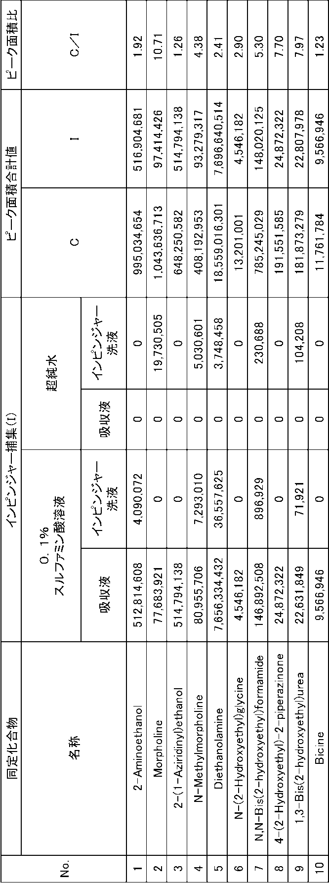
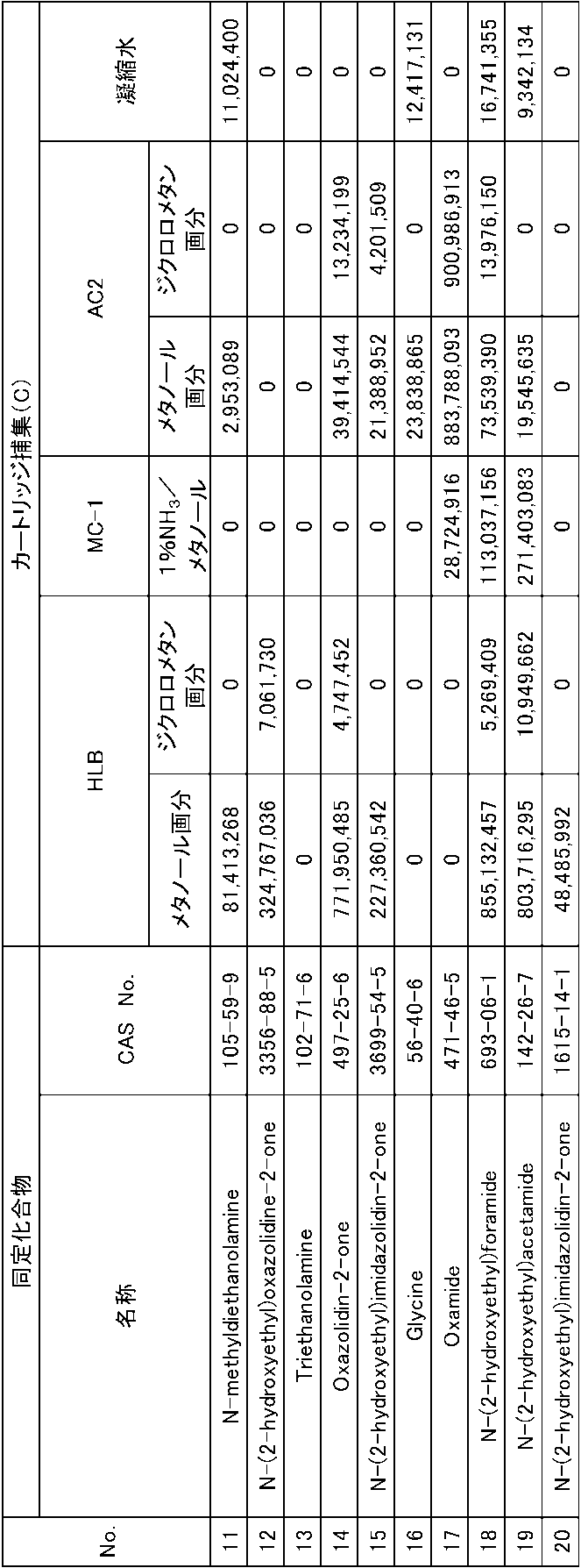
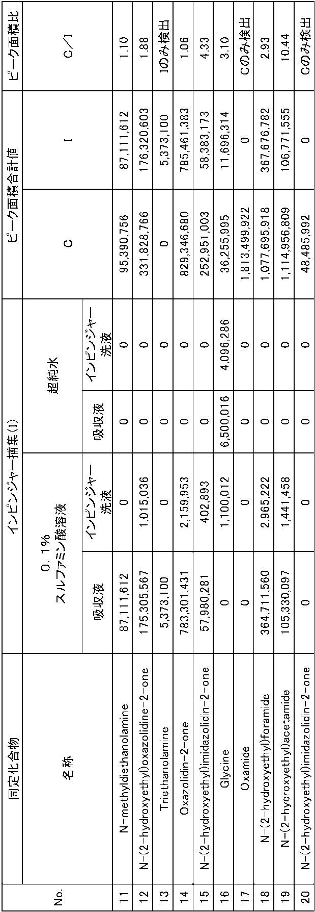
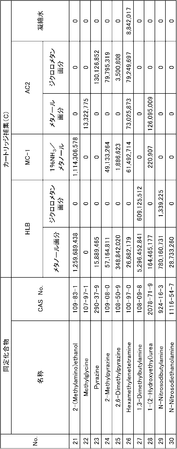
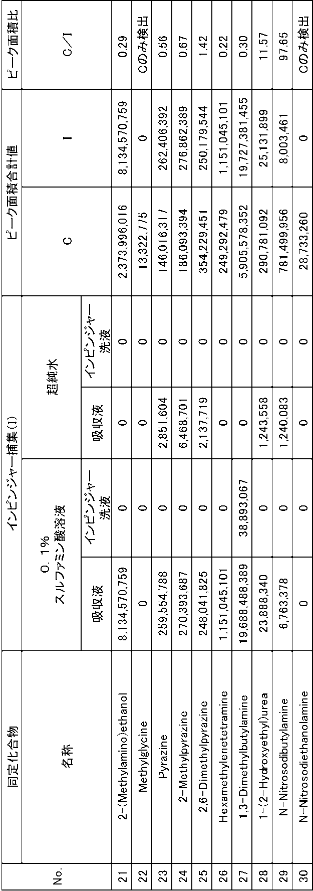
上記表1~表6に示すように、固体吸収材に実際に担持されたジエタノールアミン以外にも、二酸化炭素分離回収設備の3つのガス排出口からのガス中において、様々な成分が検出された。表5および表6に示すように、検出された成分には、ニトロソアミンであるN-ニトロソジブチルアミン(No.29)およびNDEA(No.30)も含まれていた。この検出結果から、固体吸収材を用いた二酸化炭素分離回収設備にNOxを含有した排ガスを供給した場合、固体吸収材に担持されたアミンとNOxとが反応し、ガス排出口から排出されるガス中にニトロソアミンが含まれてしまうことが分かった。そのため、100ppmを超えるNOx濃度を有する一般的な排ガスを、固体吸収材を用いた二酸化炭素分離回収プロセスによって処理する場合、これらの生成したニトロソアミンが地上へ拡散し、周囲環境を汚染する可能性がある。
二酸化炭素分離回収設備の大凡の平均的な定期修理期間(具体的には約1年間(運転期間としては約8000時間))において、ニトロソアミンの地上への拡散量を僅かな量(具体的には、ニトロソアミンの最大着地濃度が1μg/m3以下となる量)に抑制可能な処理対象ガス中のNOx濃度の上限値を以下の方法において算出した。
ニトロソアミンは、使用開始直後の二酸化炭素分離回収設備中の固体吸収材には含まれていない。NOxを含む排ガスが二酸化炭素分離回収設備に供給されることによって、NOxとジエタノールアミンが反応し、ニトロソアミンが当該設備内に徐々に蓄積される。ニトロソアミンの蓄積濃度が増加するにつれて、ニトロソアミンの揮発濃度も上昇する。本算出方法では、二酸化炭素分離回収設備の排出ライン(煙突、煙道等)からの排出ガスが大気拡散し、運転開始から8000時間までニトロソアミン(より詳細にはNDEA)の最大着地濃度が規制値を超えないようにするための二酸化炭素分離回収設備に供給される排ガス中のNOx濃度を求める。このNOx濃度の上限値の算出方法は、以下の3つの計算ステップを有する。
1)二酸化炭素分離回収設備の固体吸収材へ供給されるNOx濃度と排出ガス中のニトロソアミン排出濃度の相関関係の計算ステップ
2)大気拡散される排出ガスの希釈率の計算ステップ
3)8000時間までニトロソアミン(詳細にはNDEA)の最大着地濃度が規制値を超えないようにするための排ガス中のNOx濃度の計算ステップ
二酸化炭素分離回収設備の固体吸収材へ供給されるNOxの供給速度(流量)と供給されるNOx濃度との関係は、以下の式で表すことができる。
式:(NOxの供給速度)=(排ガス流量)×(NOx濃度)
・排ガス中の二酸化炭素濃度:15%
・二酸化炭素の回収率:90%
・固体吸収材に担持されたアミンの種類:ジエタノールアミン
・固体吸収材におけるアミンの担持量:36wt%(Micropor.Mesopor.Mater.226、p444-453(2016年)を参照)
・二酸化炭素の吸収量:2.85wt%(Micropor.Mesopor.Mater.226、p444-453(2016年)を参照)
・二酸化炭素の吸収時間:30分間(Micropor.Mesopor.Mater.226、p444-453(2016年)の22分間を考慮した上で設定)
・固体吸収材の再生時間:2.5時間(Micropor.Mesopor.Mater.62、p29-45(2003年)から、吸収と脱離にかかる時間の比率(6倍)を算出した上で設定)
・基材かさ密度:400kg/m3(関東化学(株)製球状シリカゲルのカタログ値を参照)
・吸収材かさ密度:625kg/m3(基材かさ密度とアミンの担持量から計算)
(吸収材かさ密度)×(二酸化炭素吸収量)=0.405kmol/m3
0.81kmol/(m3・h)/((二酸化炭素の回収率)×(排ガス中の二酸化炭素濃度))=134Nm3/(h・m3)
i)二酸化炭素分離回収設備の固体吸収材へ供給された排ガス中のNOxは全量固体吸収材に吸収される。
ii)NOxは二酸化炭素分離回収設備に含まれる全ての固体吸収材に均一に吸収される。
iii)NOxはジエタノールアミンと反応しNDEAとなる。すなわち、この他の吸収反応、例えば、NOxが水と反応し、硝酸または亜硝酸が生成され、ジエタノールアミンと中和反応後、塩を形成する等の反応は生じない。
iv)酸化、尿素化等のその他のジエタノールアミンの劣化機構は考慮しない。
i)ラウールの法則に基づき、固体吸収材に担持されたジエタノールアミンとニトロソアミンの混合物におけるそれぞれの化合物の蒸気圧を計算した。なお、この蒸気圧の計算結果は、揮発量は蒸気圧に依存するため、ii)以降の計算を行う際に使用した。
ii)微小時間Δtの間における、ジエタノールアミンおよびニトロソアミンの揮発量と、ジエタノールアミンのニトロソアミンへの転換量を計算した。
iii)時刻tにおけるジエタノールアミンの担持量から、ジエタノールアミンの揮発量とニトロソアミンへの転換量を減ずることで、時刻t+Δtにおけるジエタノールアミンの担持量(kmol/m3)を計算した。また、時刻tにおけるニトロソアミンの担持量から、ジエタノールアミンからニトロソアミンへの転換量を加え、ニトロソアミンの揮発量を減ずることで、時刻t+Δtにおけるニトロソアミンの担持量(kmol/m3)を計算した。
iv)時刻t=0から、ii)~iv)を繰り返すことで、時間経過に伴うジエタノールアミンおよびニトロソアミンに関する揮発とニトロソ化の挙動を予測した。
二酸化炭素分離回収設備の排出ライン(煙突、煙道等)から排出された排出ガスは、大気拡散された後、地上に到達する。その際の排出ガスの希釈率は、大気拡散のモデル式から推算することができる。
ドイツの法規(TRGS552)によると、ニトロソアミンの作業環境の曝露濃度の上限は1μg/m3である。従って、本実施例でも、同様の数値を規制値として設定した。濃度1μg/m3は、NDEAの分子量134.1(g/mol)から算出すると、NDEAのモル組成において0.167ppbである。この数値を前述の2)で算出された希釈率7.29×10-5で除すると、2.29ppmとなる。換言すると、地上の濃度の規制値と対応する二酸化炭素分離回収設備の排出ライン(煙突、煙道等)から排出された排出ガス中におけるニトロソアミン排出濃度の上限値は、2.29ppmに設定することができる。さらに、前述の1)で求めたNOx濃度を変動した場合におけるニトロソアミン排出濃度のグラフに基づくと、8000時間まで排出ガス中におけるニトロソアミン排出濃度の上限値の2.29ppmを超えないようにするための排ガス中のNOx濃度は、63.7ppm以下であることが確認できる。
10A、20A 燃焼設備
1 NOx除去設備
2 二酸化炭素分離回収設備
3 第1カートリッジ
4 第2カートリッジ
5 第3カートリッジ
6 第1インピンジャー
7 第2インピンジャー
L0 排ガス供給ライン
L1 処理対象ガス供給ライン
L2 二酸化炭素フリー排ガス排出ライン
L3 蒸気供給ライン
L4 二酸化炭素排出ライン
L5 乾燥空気供給ライン
L6 水分含有空気排出ライン
Claims (10)
- 排ガス中のNOxを除去するNOx除去設備と、
前記NOx除去設備のガス流れの後流側に設置されており、かつ、多孔質基材にアミンを担持させた固体吸収材を用いて前記NOx除去設備から供給される処理対象ガス中に含有される二酸化炭素を吸着および脱着する二酸化炭素分離回収設備と、を備え、
前記NOx除去設備から前記二酸化炭素分離回収設備へ供給される前記処理対象ガス中のNOx濃度は、63.7ppm以下である、酸性ガス分離回収システム。 - 前記NOx除去設備は、多孔質基材にアミンを担持させた固体吸収材を用いて前記排ガス中のNOxを除去する、請求項1に記載の酸性ガス分離回収システム。
- 前記NOx除去設備で用いられる前記固体吸収材は、前記二酸化炭素分離回収設備において二酸化炭素を吸着および脱着するために用いられた固体吸収材を含む、請求項2に記載の酸性ガス分離回収システム。
- 排ガス中のNOxを除去することと、
多孔質基材にアミンを担持させた固体吸収材を用いて、NOx除去後の処理対象ガス中に含有される二酸化炭素を吸着および脱着し、二酸化炭素を分離回収することと、を含み、
前記NOx除去後の処理対象ガス中のNOx濃度が、63.7ppm以下である、酸性ガス分離回収方法。 - NOxの除去では、多孔質基材にアミンを担持させた固体吸収材を用いて前記排ガス中のNOxを除去する、請求項4に記載の酸性ガス分離回収方法。
- NOxの除去で用いられる前記固体吸収材は、前記二酸化炭素を分離回収する際において、二酸化炭素を吸着および脱着するために用いられた固体吸収材を含む、請求項5に記載の酸性ガス分離回収方法。
- 排ガス中のNOxを除去するNOx除去設備と、
前記NOx除去設備のガス流れの後流側に設置されており、かつ、多孔質基材にアミンを担持させた固体吸収材を用いて前記NOx除去設備から供給される処理対象ガス中に含有される二酸化炭素を吸着および脱着する二酸化炭素分離回収設備と、を備え、
前記NOx除去設備から前記二酸化炭素分離回収設備へ供給される前記処理対象ガス中のNOx濃度は、前記二酸化炭素分離回収設備から排出される排出ガスの拡散後のニトロソアミンの最大着地濃度が予め設定された規制値以下となる値を維持できる濃度以下に設定されている、酸性ガス分離回収システム。 - 前記処理対象ガス中のNOx濃度は、前記排出ガスの拡散後のニトロソアミンの最大着地濃度が前記二酸化炭素分離回収設備の運転時間が8000時間となるまで1μg/m3以下を維持できる濃度以下に設定されている、請求項7に記載の酸性ガス分離回収システム。
- 排ガス中のNOxを除去することと、
多孔質基材にアミンを担持させた固体吸収材を用いて、NOx除去後の処理対象ガス中に含有される二酸化炭素を吸着および脱着し、二酸化炭素を分離回収することと、を含み、
前記NOx除去後の処理対象ガス中のNOx濃度は、前記二酸化炭素の分離回収後に排出される排出ガスの拡散後のニトロソアミンの最大着地濃度が予め設定された規制値以下となる値を維持できる濃度以下に設定されている、酸性ガス分離回収方法。 - 前記処理対象ガス中のNOx濃度は、前記排出ガスの拡散後のニトロソアミンの最大着地濃度が、二酸化炭素を分離回収する合計時間が8000時間となるまで1μg/m3以下を維持できる濃度以下に設定されている、請求項9に記載の酸性ガス分離回収方法。
Priority Applications (2)
| Application Number | Priority Date | Filing Date | Title |
|---|---|---|---|
| EP24836075.2A EP4725588A1 (en) | 2023-07-05 | 2024-07-03 | Acidic-gas separation/recovery system and acidic-gas separation/recovery method |
| AU2024290468A AU2024290468A1 (en) | 2023-07-05 | 2024-07-03 | Acidic-gas separation/recovery system and acidic-gas separation/recovery method |
Applications Claiming Priority (2)
| Application Number | Priority Date | Filing Date | Title |
|---|---|---|---|
| JP2023110830A JP2025008568A (ja) | 2023-07-05 | 2023-07-05 | 酸性ガス分離回収システムおよび酸性ガス分離回収方法 |
| JP2023-110830 | 2023-07-05 |
Publications (1)
| Publication Number | Publication Date |
|---|---|
| WO2025009562A1 true WO2025009562A1 (ja) | 2025-01-09 |
Family
ID=94171755
Family Applications (1)
| Application Number | Title | Priority Date | Filing Date |
|---|---|---|---|
| PCT/JP2024/024103 Ceased WO2025009562A1 (ja) | 2023-07-05 | 2024-07-03 | 酸性ガス分離回収システムおよび酸性ガス分離回収方法 |
Country Status (4)
| Country | Link |
|---|---|
| EP (1) | EP4725588A1 (ja) |
| JP (1) | JP2025008568A (ja) |
| AU (1) | AU2024290468A1 (ja) |
| WO (1) | WO2025009562A1 (ja) |
Citations (6)
| Publication number | Priority date | Publication date | Assignee | Title |
|---|---|---|---|---|
| JPH08168638A (ja) * | 1994-12-15 | 1996-07-02 | Kansai Electric Power Co Inc:The | 燃焼排ガス中の炭酸ガスと窒素酸化物を除去する方法 |
| WO2011013332A1 (ja) * | 2009-07-27 | 2011-02-03 | 川崎重工業株式会社 | 二酸化炭素分離方法及び装置 |
| JP2013121562A (ja) | 2011-12-09 | 2013-06-20 | Kawasaki Heavy Ind Ltd | 二酸化炭素分離装置 |
| JP2013202523A (ja) * | 2012-03-28 | 2013-10-07 | Toshiba Corp | 窒素酸化物/硫黄酸化物除去システム、窒素酸化物/硫黄酸化物除去方法、および二酸化炭素回収システム |
| JP6055134B1 (ja) | 2016-03-14 | 2016-12-27 | 川崎重工業株式会社 | 二酸化炭素吸着剤及びその製造方法、並びに、二酸化炭素分離回収システム |
| JP2023110830A (ja) | 2022-01-28 | 2023-08-09 | 株式会社神戸製鋼所 | 構造部材及び構造部材の製造方法、並びにバッテリートレイ及びバッテリートレイの製造方法 |
-
2023
- 2023-07-05 JP JP2023110830A patent/JP2025008568A/ja active Pending
-
2024
- 2024-07-03 AU AU2024290468A patent/AU2024290468A1/en active Pending
- 2024-07-03 EP EP24836075.2A patent/EP4725588A1/en active Pending
- 2024-07-03 WO PCT/JP2024/024103 patent/WO2025009562A1/ja not_active Ceased
Patent Citations (6)
| Publication number | Priority date | Publication date | Assignee | Title |
|---|---|---|---|---|
| JPH08168638A (ja) * | 1994-12-15 | 1996-07-02 | Kansai Electric Power Co Inc:The | 燃焼排ガス中の炭酸ガスと窒素酸化物を除去する方法 |
| WO2011013332A1 (ja) * | 2009-07-27 | 2011-02-03 | 川崎重工業株式会社 | 二酸化炭素分離方法及び装置 |
| JP2013121562A (ja) | 2011-12-09 | 2013-06-20 | Kawasaki Heavy Ind Ltd | 二酸化炭素分離装置 |
| JP2013202523A (ja) * | 2012-03-28 | 2013-10-07 | Toshiba Corp | 窒素酸化物/硫黄酸化物除去システム、窒素酸化物/硫黄酸化物除去方法、および二酸化炭素回収システム |
| JP6055134B1 (ja) | 2016-03-14 | 2016-12-27 | 川崎重工業株式会社 | 二酸化炭素吸着剤及びその製造方法、並びに、二酸化炭素分離回収システム |
| JP2023110830A (ja) | 2022-01-28 | 2023-08-09 | 株式会社神戸製鋼所 | 構造部材及び構造部材の製造方法、並びにバッテリートレイ及びバッテリートレイの製造方法 |
Non-Patent Citations (6)
| Title |
|---|
| AOYAMA MITSUNORI: "N-nitrosamine (regulation by TRGS 552 and response thereto", JOURNAL OF JAPAN RUBBER ASSOCIATION, vol. 83, no. 8, 2010, pages 25 - 28 |
| KLEPACOVA ET AL., J. CHEM. ENG. DATA, vol. 56, 2011, pages 2242 - 248 |
| MICROPOR. MESOPOR. MATER, vol. 226, 2016, pages 444 - 453 |
| MICROPOR. MESOPOR. MATER., vol. 226, 2016, pages 444 - 453 |
| MICROPOR. MESOPOR. MATER., vol. 62, 2003, pages 29 - 45 |
| R.G. KLEIN, TOXICLOGY, vol. 23, 1982, pages 135 - 147 |
Also Published As
| Publication number | Publication date |
|---|---|
| EP4725588A1 (en) | 2026-04-15 |
| AU2024290468A1 (en) | 2026-01-22 |
| JP2025008568A (ja) | 2025-01-20 |
Similar Documents
| Publication | Publication Date | Title |
|---|---|---|
| CA3077339C (en) | Gas recovery and concentration device | |
| CN102470314B (zh) | 二氧化碳分离方法及装置 | |
| JP5508279B2 (ja) | 排煙脱硫装置からの重金属の錯化および除去 | |
| CN102325579B (zh) | 一种用于控制胺排放的方法及装置 | |
| Tailor et al. | Grafted propyldiethanolamine for selective removal of SO2 in the presence of CO2 | |
| JP2012504491A (ja) | 水洗を含むチルドアンモニア系co2捕捉システム及び方法 | |
| WO2012106125A1 (en) | Gas treatment process and system | |
| KR20060112217A (ko) | 배기 가스 처리 장치 및 배기 가스 처리 방법 | |
| KR101971176B1 (ko) | 전처리 설비로부터 배출되는 휘발성 유기 화합물을 포함하는 폐가스를 처리하는 장치 | |
| KR20120066659A (ko) | 세척 용기 내에 사용된 용액을 재생하기 위한 방법 및 시스템 | |
| JP2014042904A (ja) | 飛散アミン処理装置を備えたco2回収システムおよびその制御方法 | |
| Kurniawan et al. | Technological solutions for air pollution control to mitigate climate change: an approach to facilitate global transition toward blue sky and net-zero emission | |
| KR20160140533A (ko) | 전처리 설비로부터 배출되는 휘발성 유기 화합물을 포함하는 폐가스를 처리하는 장치 | |
| CN104364002A (zh) | 防止在二氧化碳吸收过程中形成硝胺 | |
| EP2724770A1 (en) | Absorption unit for drying flue gas | |
| WO2024190323A1 (ja) | 排ガス浄化方法及び排ガス浄化装置 | |
| CN109126431A (zh) | 液相吸附式氧化还原法烟气脱硝的装置及方法 | |
| JP2025008568A (ja) | 酸性ガス分離回収システムおよび酸性ガス分離回収方法 | |
| JP2015085310A (ja) | 酸性ガス除去方法 | |
| JP2019098284A (ja) | ギ酸回収剤、ギ酸除去方法、ギ酸除去装置、二酸化炭素分離回収方法及び二酸化炭素分離回収装置 | |
| Kuettel et al. | Removal of acidic gases and metal ion contaminants with PostCapTM technology | |
| WO2013001345A1 (en) | A method of cleaning a carbon dioxide rich flue gas | |
| Sai-Obodai | A Comprehensive Evaluation of Off-Gas Emissions from a Catalyst-Aided, Amine-Based, Post Combustion Capture of CO2 from Industrial Exhaust Gas Streams | |
| CA3183175A1 (en) | Method of purification gasses with injection into liquids | |
| CN208018392U (zh) | 利用脱硫废水脱除燃煤烟气中元素态汞的装置 |
Legal Events
| Date | Code | Title | Description |
|---|---|---|---|
| 121 | Ep: the epo has been informed by wipo that ep was designated in this application |
Ref document number: 24836075 Country of ref document: EP Kind code of ref document: A1 |
|
| WWE | Wipo information: entry into national phase |
Ref document number: AU2024290468 Country of ref document: AU |
|
| WWE | Wipo information: entry into national phase |
Ref document number: 2024836075 Country of ref document: EP |
|
| ENP | Entry into the national phase |
Ref document number: 2024836075 Country of ref document: EP Effective date: 20260106 |
|
| ENP | Entry into the national phase |
Ref document number: 2024290468 Country of ref document: AU Date of ref document: 20240703 Kind code of ref document: A |
|
| ENP | Entry into the national phase |
Ref document number: 2024836075 Country of ref document: EP Effective date: 20260106 |
|
| ENP | Entry into the national phase |
Ref document number: 2024836075 Country of ref document: EP Effective date: 20260106 |
|
| NENP | Non-entry into the national phase |
Ref country code: DE |
|
| ENP | Entry into the national phase |
Ref document number: 2024836075 Country of ref document: EP Effective date: 20260106 |
|
| WWP | Wipo information: published in national office |
Ref document number: 2024836075 Country of ref document: EP |