WO2025009347A1 - 画像診断装置 - Google Patents
画像診断装置 Download PDFInfo
- Publication number
- WO2025009347A1 WO2025009347A1 PCT/JP2024/021403 JP2024021403W WO2025009347A1 WO 2025009347 A1 WO2025009347 A1 WO 2025009347A1 JP 2024021403 W JP2024021403 W JP 2024021403W WO 2025009347 A1 WO2025009347 A1 WO 2025009347A1
- Authority
- WO
- WIPO (PCT)
- Prior art keywords
- imaging
- conductive ring
- insulating member
- support shaft
- central axis
- Prior art date
- Legal status (The legal status is an assumption and is not a legal conclusion. Google has not performed a legal analysis and makes no representation as to the accuracy of the status listed.)
- Ceased
Links
Images




Classifications
-
- A—HUMAN NECESSITIES
- A61—MEDICAL OR VETERINARY SCIENCE; HYGIENE
- A61B—DIAGNOSIS; SURGERY; IDENTIFICATION
- A61B8/00—Diagnosis using ultrasonic, sonic or infrasonic waves
- A61B8/12—Diagnosis using ultrasonic, sonic or infrasonic waves in body cavities or body tracts, e.g. by using catheters
Definitions
- This disclosure relates to an imaging diagnostic device.
- Patent Document 1 discloses an ultrasound probe used in this type of diagnostic imaging catheter.
- the ultrasonic probe described in Patent Document 1 includes a rotatable rotor, an ultrasonic transducer mounted on the rotor and converting ultrasonic signals into electrical signals, a slip ring connected to the rotor so that the rotor's rotating shaft is coaxial with the rotor, and a brush that contacts the slip ring and transmits electrical signals to the ultrasonic transducer.
- the imaging diagnostic device is preferably equipped with a slip ring and brushes as disclosed in Patent Document 1.
- a slip ring and brushes as disclosed in Patent Document 1.
- An image diagnostic apparatus includes: (2) The imaging diagnostic device according to (1) above, further comprising a capture unit disposed in the sealed space and capable of capturing wear powder from the brush.
- An image diagnostic apparatus includes: (3) The slip ring is a conductive ring that forms the contact portion by contacting the brush; and an insulating member that holds the conductive ring.
- An image diagnostic apparatus includes: (4) The imaging diagnostic device according to (3) above, wherein the conductive ring is held by the insulating member so that the central axis of the outer peripheral surface of the conductive ring becomes the axis of rotation of the conductive ring by the drive motor.
- An image diagnostic apparatus includes: (5) The imaging diagnostic device according to claim 3 or 4, wherein the outer peripheral surface of the conductive ring forms a flush surface with the outer surface of the insulating member in a central axis direction along the central axis of the outer peripheral surface of the conductive ring.
- An image diagnostic apparatus includes: (6) The imaging diagnostic device according to any one of (3) to (5) above, wherein the conductive ring and the insulating member are integrally molded.
- An image diagnostic apparatus includes: (7) The imaging diagnostic device according to any one of (3) to (6) above, further comprising a support shaft that penetrates the insulating member, supports the insulating member, and is rotatable together with the imaging unit.
- An image diagnostic apparatus includes: (8) A partition body is provided to partition the sealed space therein, The imaging diagnostic device according to (7) above, wherein the support shaft penetrates the partition in a central axial direction along the central axis of the outer circumferential surface of the conductive ring.
- An image diagnostic apparatus includes: (9) a seal member for sealing between the support shaft and the partition body; The imaging diagnostic device according to (8) above, wherein a contact area between the seal member and the support shaft is smaller than a contact area between the seal member and the partition body.
- An image diagnostic apparatus includes: (10) The imaging diagnostic device is described in any one of (7) to (9) above, wherein the support shaft defines a through hole therein that penetrates in the central axial direction along the central axis of the outer circumferential surface of the conductive ring.
- An image diagnostic apparatus includes: (11) The imaging diagnostic device according to any one of (7) to (10) above, wherein the conductive ring, the insulating member, and the support shaft are integrally molded.
- An image diagnostic apparatus includes: (12) A partition body is provided to partition the sealed space therein, The imaging diagnostic device according to any one of (3) to (6) above, wherein the insulating member penetrates the partition in a central axial direction along the central axis of the outer circumferential surface of the conductive ring.
- An image diagnostic apparatus includes: (13) a seal member that seals between the insulating member and the partition body, The imaging diagnostic device according to (12) above, wherein a contact area between the sealing member and the insulating member is smaller than a contact area between the sealing member and the partition.
- An image diagnostic apparatus includes: (14) The imaging diagnostic device according to the above (12) or (13), wherein the insulating member defines a through hole therein, the through hole penetrating in a central axis direction along the central axis of the outer peripheral surface of the conductive ring.
- This disclosure provides an imaging diagnostic device that can reduce wear at the contact points between the slip ring and the brush.
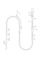
- FIG. 1 is a diagram showing an image diagnostic system including an image diagnostic apparatus according to an embodiment of the present disclosure.
- FIG. 2 is a diagram showing a catheter for diagnostic imaging alone of the diagnostic imaging system shown in FIG. 1, showing a state in which a probe and an inner tube are pushed in.
- FIG. 2 is a diagram showing a catheter for diagnostic imaging alone in the diagnostic imaging system shown in FIG. 1, showing a state in which a probe and an inner tube are pulled out.
- FIG. 2B shows the distal end of the diagnostic imaging catheter shown in FIG. 2A.
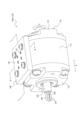
- 2 is a perspective view showing the vicinity of a slip ring and a brush of the image diagnostic apparatus shown in FIG. 1 .
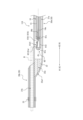
- FIG. 5 is a cross-sectional view taken along line I-I in FIG. 4 .
- FIG. 5 is a cross-sectional view taken along line II-II in FIG. 4 .
- FIG. 7 is a perspective view showing the slip rings, the brushes, and the support shaft shown in FIGS. 5 and 6 .
- 6 is an enlarged view of a portion of the seal member in FIG. 5 .
- FIG. FIG. 13 is a diagram showing a modified example of a slip ring.
- FIG. 1 is a diagram showing an imaging diagnostic system 100 including an imaging diagnostic device 120 as one embodiment of the imaging diagnostic device according to the present disclosure. As shown in FIG. 1, the imaging diagnostic system 100 includes an imaging diagnostic catheter 110 and an imaging diagnostic device 120. FIG. 1 shows a state in which the imaging diagnostic catheter 110 is connected to the imaging diagnostic device 120.
- FIGS. 2A and 2B are diagrams showing the diagnostic imaging catheter 110 shown in FIG. 1 alone. As will be described in detail later, FIGS. 2A and 2B show different positions of the longitudinal direction A of the probe 10 within the sheath 20.
- FIG. 3 is a diagram showing the distal end (hereinafter referred to as the "distal end") of the diagnostic imaging catheter 110.
- the diagnostic imaging catheter 110 is configured to be able to acquire a tomographic image of a lumen such as a blood vessel. As shown in FIG. 1, the diagnostic imaging catheter 110 is driven by being connected to a diagnostic imaging device 120. More specifically, in this embodiment, the diagnostic imaging catheter 110 is connectable to a drive unit 120a of the diagnostic imaging device 120.
- the imaging diagnostic device 120 can be connected to an imaging diagnostic catheter equipped with an imaging unit including an ultrasound transmission/reception unit.
- the imaging diagnostic device 120 of this embodiment can be connected to an imaging diagnostic catheter using IVUS, and a dual type imaging diagnostic catheter using both IVUS and OCT or OFDI.
- the imaging diagnostic device 120 may be connected to an imaging diagnostic catheter that does not include an ultrasound transmission/reception unit and has an imaging unit including an optical transmission/reception unit, in addition to an imaging diagnostic catheter equipped with an imaging unit including an ultrasound transmission/reception unit.
- the imaging diagnostic device 120 of this embodiment is configured to be connected to an imaging diagnostic catheter that uses IVUS, a dual type imaging diagnostic catheter that uses both IVUS and OCT or OFDI, as well as an imaging diagnostic catheter that does not use IVUS and uses OCT or OFDI.
- the imaging diagnostic device 120 of this embodiment can generate an intraluminal image using at least one of ultrasound and light in accordance with the imaging diagnostic catheter to be connected.
- ⁇ Diagnostic imaging catheter 110> 1 to 3 an example of a diagnostic imaging catheter connectable to the diagnostic imaging device 120 will be described.
- a dual-type diagnostic imaging catheter 110 that uses both IVUS and OCT or OFDI will be described as an example of a diagnostic imaging catheter connectable to the diagnostic imaging device 120.
- the longitudinal direction of the diagnostic imaging catheter 110 will be referred to as the "longitudinal direction A".
- the side of the diagnostic imaging catheter 110 in the longitudinal direction A that is inserted into the living body will be referred to as the "distal side”.
- the side of the diagnostic imaging catheter 110 in the longitudinal direction A that is operated outside the living body will be referred to as the "proximal side”.
- the direction from the proximal side to the distal side of the diagnostic imaging catheter 110 may be simply referred to as the "insertion direction A1".
- the direction from the distal end side to the proximal end side of the diagnostic imaging catheter 110 may be simply referred to as the "removal direction A2".
- the diagnostic imaging catheter 110 includes a probe 10, a long sheath 20, an inner tube 30, and an outer tube 40. Each part of the diagnostic imaging catheter 110 will be described in detail below.
- the probe 10 includes an imaging unit 60, a shaft 13, and an electric signal line 14a and an optical transmission line 14b extending within the shaft 13.
- the imaging unit 60 includes an ultrasonic transmitting/receiving unit 61a, an optical transmitting/receiving unit 61b, a contrast marker member 61c, a housing 61d, and a protective member 61e.
- the imaging unit 60 is fixed to the distal end of the shaft 13.
- the ultrasound transmission/reception unit 61a of the imaging unit 60 includes an ultrasound transducer 62.
- the ultrasound transducer 62 can transmit ultrasound based on a pulse signal into the cavity of the living body and receive ultrasound reflected from the living tissue surrounding the cavity.
- the ultrasound transducer 62 may include, for example, a main body and an electrode.
- the main body may include a piezoelectric element.
- the piezoelectric element includes a piezoelectric material such as ceramics or quartz.
- the ultrasound transmission/reception unit 61a can transmit and receive ultrasound using the ultrasound transducer 62.
- the ultrasound transmission/reception unit 61a shown in FIG. 3 is located distal to an optical element 61b1 (described later) of the optical transmission/reception unit 61b.
- the optical transceiver 61b is capable of continuously transmitting the transmitted light to the lumen and continuously receiving the light reflected by the biological tissue surrounding the lumen.
- the optical transceiver 61b shown in FIG. 3 includes an optical element 61b1.
- the optical element 61b1 is connected to the distal end of the optical transmission line 14b and has a lens function for focusing light and a reflecting function for reflecting light.
- the optical element 61b1 shown in FIG. 3 is a ball lens having a flat portion inclined with respect to the longitudinal direction A and a spherical portion.
- the flat portion is provided with a reflective coating that reflects light propagating from the optical transmission line 14b.
- the material of the reflective coating is not particularly limited as long as it is capable of reflecting light, and examples of such materials include aluminum.
- the light propagating from the optical transmission line 14b is reflected from the flat portion, collected from the spherical portion, and transmitted to the lumen.
- the light reflected from the biological tissue surrounding the lumen is collected from the spherical portion, reflected from the flat portion, and propagated to the optical transmission line 14b. In this way, the optical transmitting/receiving unit 61b can transmit and receive light through the optical element 61b1.
- the contrast marker member 61c has X-ray contrast properties. Specifically, the contrast marker member 61c is formed from a material that is highly X-ray opaque. Specifically, the contrast marker member 61c can be made from a material that is highly X-ray opaque, such as platinum, gold, iridium, or tungsten.
- the contrast marker member 61c shown in FIG. 3 is disposed proximal to the optical element 61b1 of the optical transmitter/receiver 61b.
- the contrast marker member 61c is fixed to the housing 61d.
- the housing 61d directly or indirectly supports the ultrasound transmitting/receiving unit 61a, the optical transmitting/receiving unit 61b, and the contrast marker member 61c.
- the proximal side of the housing 61d is connected to the shaft 13.
- the housing 61d may be integrated with the shaft 13. Therefore, the housing 61d may be directly connected to the shaft 13 by adhesion or the like, or may be indirectly connected to the shaft 13 via a connector or the like.
- a transmission/reception opening 61d1 is formed in the housing 61d.
- the transmission/reception opening 61d1 allows the passage of ultrasonic waves transmitted and received by the ultrasonic transmission/reception unit 61a and light transmitted and received by the optical transmission/reception unit 61b.
- the ultrasonic transmission/reception unit 61a can transmit ultrasonic waves based on a pulse signal to the lumen through this transmission/reception opening 61d1.
- the ultrasonic transmission/reception unit 61a can also receive ultrasonic waves reflected from the biological tissue surrounding the lumen through this transmission/reception opening 61d1.
- the optical transmission/reception unit 61b can also transmit light to the lumen through this transmission/reception opening 61d1.
- the optical transmission/reception unit 61b can also receive light reflected from the biological tissue surrounding the lumen through this transmission/reception opening 61d1.
- the ultrasonic transmitting/receiving unit 61a may be supported by the housing 61d via a backing member.
- the backing member scatters and attenuates ultrasonic waves traveling from the ultrasonic transmitting/receiving unit 61a to the opposite side of the transmitting/receiving opening 61d1 of the housing 61d.
- the configuration for fixing the backing member to the housing 61d is not particularly limited.
- the backing member may be fixed to the housing 61d by, for example, bonding with an adhesive.
- the housing 61d may be formed, for example, by cutting out a block of metal or by MIM (metal injection molding).
- the protective member 61e is attached to the housing 61d in a state where it covers the distal end of the housing 61d.
- the protective member 61e has a generally hemispherical outer shape that is convex in the insertion direction A1. Providing the protective member 61e reduces friction and snagging with the inner surface of the sheath 20, and reduces damage to the sheath 20 caused by the housing 61d.
- the protective member 61e may be made of, for example, a resin material.
- the protective member 61e may also be configured to include, for example, a coil.
- the protective member 61e may also be, for example, a resin tube member that is fitted onto and fixed to the housing 61d.
- the shaft 13 extends through the inside of the sheath 20, the inner tube 30, and the outer tube 40. As described above, the distal end of the shaft 13 is connected to the housing 61d of the imaging unit 60. The proximal end of the shaft 13 is held by the hub 32 (described below) that constitutes the proximal end of the inner tube 30.
- the electric signal line 14a extends inside the shaft 13.
- the electric signal line 14a electrically connects the ultrasonic transmission/reception unit 61a of the imaging unit 60 to the imaging diagnostic device 120 (see FIG. 1).
- a plurality of electric signal lines 14a are provided, and each electric signal line 14a is connected to an electrode of the ultrasonic transmission/reception unit 61a of the imaging unit 60.
- FIG. 3 illustrates only one electric signal line 14a.
- the plurality of electric signal lines 14a may be configured, for example, by a twisted pair cable in which two electric signal lines 14a are twisted together.
- Each electric signal line 14a may be a flexible thin wire member having an outer diameter greater than 0 mm and equal to or less than 0.1 mm.
- Each electric signal line 14a may be configured, for example, by a conductor and a covering material formed of an insulating material that covers the conductor.
- the optical transmission line 14b extends inside the shaft 13.
- the optical transmission line 14b optically connects the optical transmitter/receiver 61b of the imaging unit 60 to the image diagnostic device 120 (see FIG. 1).
- the optical transmission line 14b is connected to the optical element 61b1 of the optical transmitter/receiver 61b of the imaging unit 60.
- the optical transmission line 14b includes, for example, an optical fiber as an optical transmission path.
- the guidewire insertion section 20b may be provided with a contrast marker section 23 having X-ray contrast properties.
- the contrast marker portion 23 can be made of a metal pipe or a metal coil having high X-ray opacity, such as platinum, gold, iridium, or tungsten.
- the tubular guidewire insertion portion 20b shown in Fig. 3 is adjacent to the distal end of the tubular main body portion 20a so as to be parallel to each other.
- the main body portion 20a and the guidewire insertion portion 20b may be formed by joining different tubular members by heat fusion or the like.
- the distal end of the main body 20a is provided with a communication hole 22a1 that connects the inside and outside of the first hollow portion 21a.
- the distal end of the main body 20a may be provided with a reinforcing member 22 for firmly joining and supporting the guidewire insertion portion 20b.
- the reinforcing member 22 is provided with a communication passage 22a that connects the inside of the first hollow portion 21a, which is located proximal to the reinforcing member 22, with the communication hole 22a1.
- the reinforcing member 22 does not have to be provided at the distal end of the main body 20a.
- the communication hole 22a1 is a priming liquid discharge hole for discharging the priming liquid.
- a priming process is performed in which the priming liquid is filled into the main body 20a of the sheath 20.
- the priming liquid is released to the outside from the communication hole 22a1, and gas such as air can be discharged from the main body 20a of the sheath 20 together with the priming liquid.
- the sheath 20 and the reinforcing member 22 are preferably made of a flexible material, but the material is not particularly limited.
- constituent materials include various thermoplastic elastomers such as styrene-based, polyolefin-based, polyurethane-based, polyester-based, polyamide-based, polyimide-based, polybutadiene-based, trans-polyisoprene-based, fluororubber-based, and chlorinated polyethylene-based, and combinations of one or more of these (polymer alloys, polymer blends, laminates, etc.) can also be used.
- a hydrophilic lubricating coating layer that exhibits lubricity when wet may be disposed on the outer surface of the sheath 20.
- the inner tube 30 accommodates the proximal end of the shaft 13 and is movable within the outer tube 40 together with the shaft 13.
- the inner tube 30 includes an inner tube body 31 and a hub 32.
- the inner tube body 31 is inserted within the outer tube 40 so as to be movable back and forth.
- the hub 32 is connected to the proximal side of the inner tube body 31.
- the outer tube 40 is fixed to the proximal end of the sheath 20.
- the outer tube 40 comprises an outer tube main body 41, a distal connector 42, and a proximal connector 43.
- the outer tube main body 41 is located radially outside the inner tube main body 31, and the inner tube main body 31 moves back and forth within the outer tube main body 41.
- the distal connector 42 connects the proximal end of the main body 20a of the sheath 20 and the distal end of the outer tube main body 41.
- the proximal connector 43 is fixed to the proximal end of the outer tube main body 41.
- the shaft 13, electrical signal line 14a, and optical transmission line 14b of the probe 10 described above extend from the main body 20a of the sheath 20, through the outer tube 40 connected to the proximal side of the main body 20a, to the hub 32 that constitutes the proximal end of the inner tube 30.
- the above-mentioned probe 10 and inner tube 30 are connected to each other so that they can move forward and backward in the longitudinal direction A as a unit. Therefore, for example, when the inner tube 30 is pushed in the insertion direction A1, the inner tube 30 is pushed into the outer tube 40 in the insertion direction A1. When the inner tube 30 is pushed into the outer tube 40 in the insertion direction A1, the probe 10 connected to the inner tube 30 moves in the insertion direction A1 inside the main body 20a of the sheath 20. This results in the pushed-in state shown in FIG. 2A. When the inner tube 30 is pulled in the removal direction A2 from the pushed-in state shown in FIG. 2A, the inner tube 30 is pulled out from the outer tube 40 in the removal direction A2.
- the diagnostic imaging device 120 can move the probe 10 and the inner tube 30 in the removal direction A2 while rotating the probe 10 from the pushed-in state shown in FIG. 2A to the pulled-out state shown in FIG. 2B.
- this operation may be referred to as the "pullback imaging operation.”
- the diagnostic imaging device 120 can generate a tomographic image of a lumen such as a blood vessel as an intracavity image over a predetermined range in the longitudinal direction A.
- the diagnostic imaging device 120 includes a first drive motor 121 which is a power source for rotating the probe 10 (see FIG. 2A, etc.) of the diagnostic imaging catheter 110. That is, the imaging unit 60 of the diagnostic imaging catheter 110 is rotationally driven by the first drive motor 121 and can rotate around the central axis O (see FIG. 3) of the shaft 13. Also, as shown in FIG. 1, the diagnostic imaging device 120 includes a second drive motor 122 which is a power source for moving the probe 10 and the inner tube 30 (see FIG. 2A, etc.) in the longitudinal direction A.
- the rotational motion of the second drive motor 122 is converted into axial motion by, for example, a ball screw 123 connected to the second drive motor 122.
- the diagnostic imaging device 120 can execute a pull-back imaging operation in which the probe 10 and the inner tube 30 are moved in the removal direction A2 while rotating the probe 10 of the diagnostic imaging catheter 110 connected thereto.
- the imaging diagnostic device 120 of this embodiment includes a drive unit 120a, a control unit 120b, and a display unit 120c capable of displaying an image generated by the control unit 120b based on the ultrasonic and light reception signals received from the imaging diagnostic catheter 110.
- the first drive motor 121, the second drive motor 122, and the ball screw 123 described above in this embodiment are provided in the drive unit 120a.
- the operation of this drive unit 120a is controlled by the control unit 120b.
- the diagnostic imaging catheter 110 can be connected to the drive unit 120a.
- the driving unit 120a includes a connection detector 124 capable of detecting the connection of the diagnostic imaging catheter 110. Furthermore, the connection detector 124 may detect the presence or absence of the ultrasonic transmission/reception unit 61a of the diagnostic imaging catheter 110 based on an electrical connection with the ultrasonic transmission/reception unit 61a (see FIG. 3) of the diagnostic imaging catheter 110. Furthermore, the connection detector 124 may detect the presence or absence of the optical transmission/reception unit 61b of the diagnostic imaging catheter 110 based on an optical connection with the optical transmission/reception unit 61b (see FIG. 3) of the diagnostic imaging catheter 110.
- the diagnostic imaging device 120 may detect, by the connection detector 124, whether the connected diagnostic imaging catheter 110 includes the ultrasonic transmission/reception unit 61a and whether the connected diagnostic imaging catheter 110 includes the optical transmission/reception unit 61b in addition to detecting the connection of the diagnostic imaging catheter 110.
- the control unit 120b includes a processor, such as a general-purpose processor such as a CPU (central processing unit) or an MPU (Micro Processing Unit), or a dedicated processor specialized for a specific process.
- the control unit 120b executes processes related to the operation of the imaging diagnostic device 120 while controlling each part of the imaging diagnostic device 120. Specifically, the control unit 120b controls the operation of the first drive motor 121 and the second drive motor 122 of the drive unit 120a. As described above, the control unit 120b can generate an intraluminal image based on the ultrasonic and light reception signals received from the imaging diagnostic catheter 110. Furthermore, the control unit 120b can display the generated intraluminal image on the display unit 120c by controlling the display unit 120c.
- the control unit 120b may further include a storage unit, such as a ROM (read only memory) or a RAM (random access memory).
- the display unit 120c is, for example, a display.
- the display unit 120c is, for example, an LCD, an organic EL display, or an HMD.
- LCD is an abbreviation for Liquid Crystal Display.
- EL is an abbreviation for Electro Luminescence.
- HMD is an abbreviation for Head-Mounted Display.
- the drive unit 120a and the control unit 120b are electrically connected.
- the display unit 120c and the control unit 120b are also electrically connected.
- the image diagnostic device 120 of this embodiment is equipped with a drive unit called MDU including the drive unit 120a, a processing unit including the control unit 120b, and a display as the display unit 120c.
- MDU is an abbreviation for Motor Drive Unit.
- the drive unit and the processing unit are connected by a cable. The cable is used to connect the drive unit and the processing unit to send and receive information.
- the processing unit and the display may also be connected by any cable.
- the image diagnostic device 120 of this embodiment is configured such that the drive unit, the processing unit, and the display are connected by cables.
- the image diagnostic device 120 is not limited to this configuration.
- the imaging diagnostic device 120 may be configured as a single device including the above-mentioned drive unit 120a, control unit 120b, and display unit 120c.
- the image diagnostic device 120 is not limited to the configuration shown in this embodiment, and may be configured to further include an external input unit such as a keyboard, for example.
- the diagnostic imaging device 120 includes a slip ring 130 and a brush 140. More specifically, in this embodiment, the driving unit 120a of the diagnostic imaging device 120 includes the slip ring 130 and the brush 140.
- FIG. 1 shows a schematic arrangement of the slip ring 130 and the brush 140 in the diagnostic imaging device 120.
- the arrangement of the slip ring 130 and the brush 140 in the diagnostic imaging device 120 will be described in detail below.
- FIG. 4 is a perspective view showing the vicinity of the slip ring 130 and the brush 140 in the drive unit 120a of the diagnostic imaging device 120.
- FIG. 5 is a cross-sectional view taken along line I-I in FIG. 4.
- FIG. 6 is a cross-sectional view taken along line II-II in FIG. 4.
- the imaging diagnostic device 120 of this embodiment includes, in addition to the slip ring 130 and the brush 140, a support shaft 150, a partition body 170, a seal member 190, and liquid lubricant X.
- Figure 7 is a perspective view showing the slip ring 130, the brush 140, and the support shaft 150 shown in Figures 5 and 6.
- the imaging diagnostic device 120 is provided with a slip ring 130 and a brush 140, which makes it possible to maintain electrical connection between the ultrasonic transmission/reception unit 61a (see Figure 3) as a rotating body of the imaging diagnostic catheter 110 and the imaging diagnostic device 120 as a stationary body while suppressing physical twisting of the connection portion.
- the slip ring 130 is electrically connected to the ultrasound transmission/reception unit 61a (see FIG. 3) of the imaging unit 60 when the diagnostic imaging catheter 110 is connected to the drive unit 120a of the diagnostic imaging device 120 (see FIG. 1).
- the slip ring 130 of this embodiment is electrically connected to the ultrasound transmission/reception unit 61a (see FIG. 3) via a conductive member 201 described later and an electrical signal line 14a (see FIG. 3) of the diagnostic imaging catheter 110.
- the slip ring 130 also rotates with the rotational motion of the first drive motor 121. That is, the slip ring 130 can be rotated together with the imaging unit 60 (see FIG. 3) of the diagnostic imaging catheter 110 by the first drive motor 121. Also, as shown in FIG.
- the slip ring 130 is fixed to a holding unit 160 capable of holding the shaft 13 of the diagnostic imaging catheter 110 when it is connected to the drive unit 120a of the diagnostic imaging device 120. More specifically, the slip ring 130 of this embodiment is indirectly fixed to the holding part 160 via the support shaft 150 (see FIGS. 4 to 7) held by the holding part 160. This allows the slip ring 130 to rotate together with the imaging part 60 (see FIG. 3) by the first drive motor 121.
- the slip ring 130 of this embodiment includes a metallic conductive ring 131 and an insulating member 132.
- the conductive ring 131 forms a contact portion 180 by contacting the brush 140.
- the insulating member 132 holds the conductive ring 131. More specifically, the insulating member 132 of this embodiment is cylindrical, and the conductive ring 131 is held on the outer surface 132a of the insulating member 132.
- the direction along the central axis O of the outer circumferential surface 131a of the conductive ring 131 is referred to as the "central axis direction B.”
- the direction around the central axis O of the outer circumferential surface 131a of the conductive ring 131 is referred to as the "circumferential direction C.”
- the radial direction of a virtual circle centered on the central axis O of the outer circumferential surface 131a of the conductive ring 131 is referred to as the "radial direction D.”
- multiple conductive rings 131 are arranged at intervals in the central axis direction B on the outer surface 132a of the insulating member 132.
- the conductive ring 131 and the insulating member 132 of this embodiment are integrally molded.
- the metallic conductive ring 131 of this embodiment is integrally molded on the outer surface 132a of the cylindrical resin insulating member 132.
- the metal material constituting the conductive ring 131 is not particularly limited as long as it is a conductive material, and may be, for example, a bronze, brass, silver, or gold alloy.
- the resin material constituting the insulating member 132 is not particularly limited as long as it is an insulating material, and may be, for example, polycarbonate or FRP-based resin. "FRP" is an abbreviation for Fiber Reinforced Plastic.
- the conductive ring 131 and the insulating member 132 are integrally molded, so that the conductive ring 131 and the insulating member 132 are in close contact with each other and no gap is formed between them. Therefore, the liquid lubricant X contained in the sealed space S partitioned by the partition body 170 described later is unlikely to penetrate between the conductive ring 131 and the insulating member 132.
- the conductive ring 131 and the insulating member 132 are not limited to being integrally molded.
- the conductive ring 131 and the insulating member 132 may be bonded, for example, via an adhesive.
- the adhesive serves as a seal between the conductive ring 131 and the insulating member 132, and the liquid lubricant X can be prevented from penetrating between the conductive ring 131 and the insulating member 132.
- the conductive ring 131 and the insulating member 132 are integrally molded, the relative positional accuracy of the conductive ring 131 and the insulating member 132 can be improved.
- the conductive ring 131 and the insulating member 132 are not integrally molded but are joined via a seal member such as an adhesive, the conductive ring 131 and the insulating member 132 can be easily manufactured, and the manufacturing efficiency of the slip ring 130 can be improved.
- the conductive ring 131 of this embodiment is held by the insulating member 132 so that the central axis O of the outer circumferential surface 131a of the conductive ring 131 becomes the axis of rotation of the conductive ring 131 by the first drive motor 121.
- the position in the radial direction D of the contact portion 180 between the outer circumferential surface 131a of the conductive ring 131 and the brush 140 described later is stabilized.
- the central axis of the support shaft 150 which will be described later, becomes the rotation axis of the conductive ring 131. Therefore, for example, in the manufacturing process of the image diagnostic device 120, the outer surface of the slip ring 130 supported by the support shaft 150 is ground while rotating the support shaft 150 around its central axis. This allows the central axis of the support shaft 150, which becomes the rotation axis of the conductive ring 131, to coincide with the central axis O of the outer peripheral surface 131a of the conductive ring 131. In this way, the rotation axis of the conductive ring 131 and the central axis O of the outer peripheral surface 131a of the conductive ring 131 can be easily coincident.
- the central axis O of the outer peripheral surface 131a of the conductive ring 131 and the rotation axis of the conductive ring 131 by the first drive motor 121 may be aligned by a method other than the above-mentioned method.
- the outer peripheral surface 131a of the conductive ring 131 forms a surface flush with the outer surface 132a of the insulating member 132 in the central axis direction B. More specifically, in this embodiment, the conductive ring 131 is embedded on the outer surface 132a of the insulating member 132 so that the outer peripheral surface 131a forms a surface flush with the outer surface 132a of the cylindrical insulating member 132.
- the outer peripheral surface 131a of the conductive ring 131 and the outer surface 132a of the insulating member 132 form a flush surface, and therefore the step between the outer peripheral surface 131a of the conductive ring 131 and the outer surface 132a of the insulating member 132 can prevent the liquid lubricant X and air bubbles from remaining in the sealed space S described below.
- “flush” means that the liquid lubricant X and air bubbles described above can be prevented from accumulating, and includes not only a configuration in which no steps are formed at all, but also a step of 0.1 mm or less.
- the conductive ring 131 and the insulating member 132 of this embodiment are integrally molded as described above. Therefore, in this embodiment, the conductive ring 131 is embedded in the outer surface 132a of the insulating member 132, so that the outer peripheral surface 131a of the conductive ring 131 and the outer surface 132a of the insulating member 132 form a flush surface, but the method of forming this flush surface is not particularly limited.
- the conductive ring 131 and the insulating member 132 having an annular recess formed on the outer surface 132a may be formed separately. Then, the conductive ring 131 may be disposed in the annular recess on the outer surface 132a of the insulating member 132. In this way, the outer peripheral surface 131a of the conductive ring 131 may form a flush surface with the outer surface 132a of the insulating member 132.
- the brush 140 is electrically connected to the slip ring 130 by contacting the slip ring 130. More specifically, in this embodiment, the brush 140 forms a contact portion 180 with the slip ring 130 by contacting the conductive ring 131 held on the outer surface 132a of the insulating member 132. The slip ring 130 and the brush 140 are electrically connected by this contact portion 180.
- the brush 140 is also configured to be able to slide on the outer circumferential surface of the slip ring 130 which is rotated by the first drive motor 121. More specifically, the brush 140 of this embodiment is able to slide on the slip ring 130 by the contact portion 180 which comes into contact with the outer circumferential surface 131a of the conductive ring 131 of the slip ring 130.
- multiple brushes 140 are arranged at intervals in the central axial direction B.
- the position of the brushes 140 in the central axial direction B corresponds to the position of the conductive ring 131 in the central axial direction B. Therefore, each brush 140 comes into contact with the conductive ring 131 arranged at the corresponding position.
- two brushes 140 come into contact with one conductive ring 131.
- two contact portions 180 are formed with one conductive ring 131. These two contact portions 180 are formed at positions that are approximately opposite each other in the radial direction D.
- the brush 140 of this embodiment includes a long brush body 141 that contacts the conductive ring 131 of the slip ring 130, and a holder 142 that holds the brush body 141.
- the brush body 141 of this embodiment is made of a metal wire member that is held in a cantilevered manner by the holder 142 so that its tip side can be elastically bent.
- the metal material that constitutes the brush body 141 may be, for example, a copper-silver alloy.
- the brush body 141 is brought into contact with the conductive ring 131 located on the outer circumferential surface of the slip ring 130 so that the brush body 141 is in a state in which it can be elastically bent. In this way, in this embodiment, the restoring force of the brush body 141 in a state in which it is elastically bent is used to ensure a predetermined contact pressure of the brush body 141 to the slip ring 130.
- the support shaft 150 passes through the insulating member 132 of the slip ring 130 and supports the insulating member 132.
- the support shaft 150 of this embodiment is held by the holding portion 160 (see Figure 1).
- the support shaft 150 rotates together with the holding portion 160 by the first drive motor 121.
- the support shaft 150 can rotate together with the imaging portion 60 (see Figure 3) by the first drive motor 121.
- the slip ring 130 is supported by the support shaft 150 so as to be rotatable together with the support shaft 150.
- the support shaft 150 of this embodiment defines a through hole 150a therein that penetrates in the central axial direction B.
- an optical transmission member 200 that is optically connected to the optical transmission/reception unit 61b (see Figure 3) of the diagnostic imaging catheter 110 may be disposed in this through hole 150a.
- the optical transmission member 200 of this embodiment can be optically connected to the optical transmission/reception unit 61b via the optical transmission line 14b.
- the support shaft 150 of this embodiment is formed with a storage hole 150b in which the conductive member 201 is stored.
- the support shaft 150 of this embodiment is formed with three storage holes 150b around the through hole 150a.
- the conductive member 201 stored in the storage hole 150b can electrically connect the conductive ring 131 of the slip ring 130 and the electrical signal line 14a (see Fig. 3) of the diagnostic imaging catheter 110.
- the support shaft 150 penetrates the partition body 170 in the central axial direction B. More specifically, in this embodiment, the support shaft 150 penetrates the partition body 170 in the central axial direction B so as to pass through the sealed space S that the partition body 170 defines therein.
- the support shaft 150 of this embodiment is integrally molded with the conductive ring 131 and the insulating member 132. That is, in this embodiment, the conductive ring 131, the insulating member 132, and the support shaft 150 are integrally molded. Specifically, the metallic support shaft 150 of this embodiment, the resin insulating member 132 supported on the outer surface of the support shaft 150, and the metallic conductive ring 131 supported on the outer surface 132a of the insulating member 132 are integrally molded. Therefore, the conductive ring 131 and the insulating member 132 are in close contact with each other, and no gap is formed between them. Furthermore, the insulating member 132 and the support shaft 150 are in close contact with each other, and no gap is formed between them.
- the liquid lubricant X contained in the sealed space S partitioned by the partition body 170 described later is unlikely to penetrate between the conductive ring 131 and the insulating member 132, and between the insulating member 132 and the support shaft 150.
- the conductive ring 131, the insulating member 132, and the support shaft 150 are not limited to being integrally molded.
- the conductive ring 131 and the insulating member 132 may be bonded to each other, for example, via an adhesive.
- the insulating member 132 and the support shaft 150 may be bonded to each other, for example, via an adhesive.
- the adhesive serves as a seal member between the conductive ring 131 and the insulating member 132, and between the insulating member 132 and the support shaft 150. Therefore, it is possible to suppress the liquid lubricant X from penetrating between the conductive ring 131 and the insulating member 132, and between the insulating member 132 and the support shaft 150.
- the conductive ring 131, the insulating member 132, and the support shaft 150 are integrally molded, it is possible to improve the relative positional accuracy of the conductive ring 131, the insulating member 132, and the support shaft 150.
- the conductive ring 131, insulating member 132, and support shaft 150 are not integrally molded but are joined via a sealing member such as an adhesive, the conductive ring 131, insulating member 132, and support shaft 150 are each easy to manufacture, and the manufacturing efficiency of the slip ring 130 and support shaft 150 can be improved.
- the support shaft 150 is made of metal, but it may also be made of resin.
- the partition 170 defines an enclosed space S therein. More specifically, the enclosed space S in this embodiment is defined by the partition 170 and the holder 142 of the brush 140.
- the enclosed space S is filled with liquid lubricant X.
- the contact portion 180 of the slip ring 130 and the brush 140 is disposed in the enclosed space S which is filled with liquid lubricant X. In this manner, wear at the contact portion 180 can be suppressed. As a result, the generation of wear powder from the contact portion 180 can be suppressed.
- liquid lubricant X there are no particular limitations on the type of liquid lubricant X, so long as it is capable of reducing the sliding resistance at the contact portion 180 of the slip ring 130 and the brush 140.
- the liquid lubricant X may be a product name "Specialty Solvent Vertrel (registered trademark) XF" by Chemours.
- the partition 170 of this embodiment comprises a cylindrical body 171, a first wall 172 closing one end of the cylindrical body 171, and a second wall 173 closing the other end of the cylindrical body 171.
- the internal space surrounded by the cylindrical body 171, the first wall 172, and the second wall 173 is the sealed space S.
- an opening 171a communicating with the internal space is formed in the peripheral wall of the cylindrical body 171 of this embodiment.
- the brush 140 is fixed to the cylindrical body 171 such that the brush main body 141 enters the internal space from the opening 171a of the cylindrical body 171 and the plate-shaped holder 142 closes the opening 171a of the cylindrical body 171.
- a seal member 143 such as a rubber member is sandwiched between the edge of the opening 171a of the cylindrical body 171 and the holder 142 of the brush 140. In this way, an enclosed space S is defined by the partition body 170 and the holder 142 of the brush 140.
- the first wall 172 and the second wall 173 are formed with insertion holes 172a and 173a through which the support shaft 150 passes.
- a bearing member 176 that rotatably supports the support shaft 150 is provided in the insertion holes 172a and 173a of the first wall 172 and the second wall 173, respectively.
- the support shaft 150 extends in the central axial direction of the cylindrical body 171 so as to pass through the sealed space S, and penetrates the insertion holes 172a and 173a of the first wall 172 and the second wall 173, respectively.
- the support shaft 150 is rotatably supported by the bearing member 176 provided in the insertion holes 172a and 173a of the first wall 172 and the second wall 173, respectively.
- the partition 170 of this embodiment is configured to include a cylindrical body 171, a first wall body 172, and a second wall body 173, but is not limited to this configuration. Any other configuration may be used as long as it is configured to partition an enclosed space S in which the contact portion 180 of the slip ring 130 and the brush 140 are disposed.
- partition body 170 in this embodiment is made of metal, it may also be made of resin.
- the partition body 170 of this embodiment is disposed in the sealed space S and includes a capture portion 175 capable of capturing wear powder from the brush 140. Even if wear powder is generated from the contact portion 180, the capture portion 175 can capture the wear powder, thereby preventing the wear powder from floating in the sealed space S.
- the cylindrical body 171 of the partition body 170 of this embodiment includes a cylindrical main body 174 and a capture portion 175 protruding from the inner surface of the cylindrical main body 174 toward the sealed space S.
- the capture portion 175 includes a capture main body portion 175a protruding from the inner surface of the cylindrical main body 174 inward in the radial direction of the cylindrical main body 174 (a direction substantially equal to the radial direction D), and a bent portion 175b protruding from the tip of the capture main body portion 175a in the circumferential direction C of the cylindrical main body 174. As shown in FIG. 6, the bent portion 175b protrudes from the capture body 175a in the opposite direction C2 to the rotation direction C1 during the pullback imaging operation of the diagnostic imaging catheter 110 (see FIGS. 1 to 3) by the first drive motor 121 (see FIG. 1).
- the partition 170 is configured to include the capture portion 175, but this is not limited to the configuration.
- the capture portion 175 may be configured, for example, by a capture member that is placed in the sealed space S separately from the partition 170.
- the seal member 190 seals between the support shaft 150 and the partition body 170. More specifically, the seal member 190 of this embodiment seals between the outer surface of the support shaft 150 and the inner surface of the insertion holes 172a, 173a of the first wall body 172 and the second wall body 173 of the partition body 170 at the insertion holes 172a, 173a of the first wall body 172 and the second wall body 173, respectively. In this way, the liquid lubricant X filled in the sealed space S can be further prevented from leaking out of the sealed space S through the insertion holes 172a, 173a of the first wall body 172 and the second wall body 173, respectively. In other words, the liquid-tightness of the sealed space S can be further improved.
- the seal member 190 of this embodiment is a ring body that extends endlessly in the circumferential direction of the support shaft 150.
- the ring-shaped seal member 190 of this embodiment has, in a cross-sectional view along its central axis direction, a first contact portion 191 that contacts the support shaft 150 and a second contact portion 192 that contacts the partition body 170.
- the first contact portion 191 and the second contact portion 192 are arranged to face each other in the radial direction D and are connected via a bent portion 193.
- the first contact portion 191 and the second contact portion 192 are displaced toward each other in the radial direction D by increasing the degree of bending of the bent portion 193.
- first contact portion 191 and the second contact portion 192 are displaced away from each other in the radial direction D by decreasing the degree of bending of the bent portion 193.
- the seal member 190 of this embodiment is sandwiched between the outer surface of the support shaft 150 and the inner surface of the insertion holes 172a, 173a of the partition body 170, with the degree of bending of the bent portion 193 increased against the elastic restoring force. Therefore, the first contact portion 191 and the second contact portion 192 of the seal member 190 are in close contact with the outer surface of the support shaft 150 and the inner surface of the insertion holes 172a, 173a of the partition body 170 due to the elastic restoring force of the bent portion 193 trying to return to its original state. This allows the seal member 190 of this embodiment to seal between the support shaft 150 and the partition body 170.
- the contact area of the contact surface Y1 between the seal member 190 and the support shaft 150 is smaller than the contact area of the contact surface Y2 between the seal member 190 and the partition body 170.
- the support shaft 150 can rotate more easily relative to the partition body 170 while still achieving sealing between the support shaft 150 and the partition body 170 by the seal member 190.
- the second contact portion 192 does not have a protrusion that protrudes outward in the radial direction D (upward in FIG. 8), whereas the first contact portion 191 has a protrusion 191a that protrudes inward in the radial direction D (downward in FIG. 8).
- the second contact portion 192 contacts the inner surface of the insertion holes 172a, 173a over a wide range in the central axis direction B, while the first contact portion 191 contacts the outer surface of the support shaft 150 over a narrow range only at the position of the protrusion 191a in the central axis direction B.
- the configuration of the seal member 190 is not limited to the configuration of this embodiment.
- the contact area of the contact surface Y1 between the seal member 190 and the support shaft 150 may be made smaller than the contact area of the contact surface Y2 between the seal member 190 and the partition body 170 by using a seal member 190 having a shape different from that of this embodiment.
- the slip ring 230 shown in FIG. 9 includes a conductive ring 131 and an insulating member 232.
- the conductive ring 131 of this embodiment has the same configuration as that described above, so a description thereof will be omitted here.
- the insulating member 232 has a different configuration from the insulating member 132 (see FIG. 5, etc.) described above. Specifically, the insulating member 232 of this embodiment differs in configuration from the insulating member 132 (see FIG. 5, etc.) described above in that the insulating member 132 (see FIG. 5, etc.) and the support shaft 150 (see FIG. 5, etc.) described above are formed from an integrated resin material. In other words, in this embodiment, the metallic support shaft 150 (see FIG. 5, etc.) described above is not provided, and the insulating member 232 has the function of the insulating member 132 (see FIG. 5, etc.) described above as well as the function of the metallic support shaft 150 (see FIG. 5, etc.).
- the other configurations of the imaging diagnostic device 120 shown in FIG. 9 are the same as those of the above-mentioned embodiment.
- the insulating member 232 penetrates the partition 170 in the central axis direction B along the central axis O of the outer circumferential surface 131a of the conductive ring 131, similar to the support shaft 150 described above (see FIG. 5, etc.).
- the support configuration of the insulating member 232 by the partition 170 is similar to the support configuration of the support shaft 150 by the partition 170 described above (see FIG. 5, etc.).
- the sealing member 190 seals between the insulating member 232 and the partition body 170.
- the contact area of the contact surface Y3 between the sealing member 190 and the insulating member 232 is smaller than the contact area of the contact surface Y4 between the sealing member 190 and the partition body 170.
- the insulating member 232 defines a through hole 232a therein, which penetrates in the direction of the central axis O of the conductive ring 131.
- an optical transmission member 200 that is optically connected to the optical transmitter/receiver 61b (see FIG. 3) of the diagnostic imaging catheter 110 may be disposed, for example, as in the through hole 150a (see FIG. 5, etc.) of the support shaft 150 described above.
- the insulating member 232 is formed with a housing hole 232b in which the conductive member 201 is housed.
- the conductive member 201 housed in the housing hole 232b can electrically connect the conductive ring 131 of the slip ring 130 and the electrical signal line 14a (see FIG. 3) of the diagnostic imaging catheter 110.
- the outer peripheral surface 131a of the conductive ring 131 forms a surface flush with the outer surface 232c of the insulating member 232 in the central axis direction B.
- the insulating member 232 of the slip ring 230 itself may be configured to double as the support shaft 150 (see FIG. 5, etc.) of the above-mentioned embodiment.
- an imaging diagnostic catheter 110 equipped with both an ultrasonic transmission/reception unit 61a and an optical transmission/reception unit 61b is connected to the imaging diagnostic device 120, but an imaging diagnostic catheter equipped with an ultrasonic transmission/reception unit 61a but not an optical transmission/reception unit 61b may be connected to the imaging diagnostic device 120.
- This disclosure relates to an imaging diagnostic device.
- Probe 13 Shaft 14a: Electric signal line 14b: Optical transmission line 20: Sheath 20a: Main body 20b: Guide wire insertion section 21a: First hollow section 21b: Second hollow section 22: Reinforcing member 22a: Communication passage 22a1: Communication hole 23: Contrast marker section 30: Inner tube 31: Inner tube main body 32: Hub 40: Outer tube 41: Outer tube main body 42: Distal connector 43: Proximal connector 60: Imaging section 61a: Ultrasound transmission/reception section 61b: Optical transmission/reception section 61b1: Optical element 61 c: contrast marker member 61d: housing 61e: protective member 62: ultrasound transducer 100: diagnostic imaging system 110: diagnostic imaging catheter 120: diagnostic imaging device 120a: drive unit 120b: control unit 120c: display unit 121: first drive motor 122: second drive motor 123: ball screw 124: connection detection unit 130, 230: slip ring 131: conductive ring 131a: outer circumferential surface 132,
Landscapes
- Life Sciences & Earth Sciences (AREA)
- Health & Medical Sciences (AREA)
- Biomedical Technology (AREA)
- Biophysics (AREA)
- Nuclear Medicine, Radiotherapy & Molecular Imaging (AREA)
- Pathology (AREA)
- Radiology & Medical Imaging (AREA)
- Engineering & Computer Science (AREA)
- Physics & Mathematics (AREA)
- Heart & Thoracic Surgery (AREA)
- Medical Informatics (AREA)
- Molecular Biology (AREA)
- Surgery (AREA)
- Animal Behavior & Ethology (AREA)
- General Health & Medical Sciences (AREA)
- Public Health (AREA)
- Veterinary Medicine (AREA)
- Ultra Sonic Daignosis Equipment (AREA)
Abstract
本開示に係る画像診断装置は、超音波送受信部を含む撮像部を備える画像診断用カテーテルと接続可能であり、腔内画像を生成可能な画像診断装置であって、前記撮像部を回転駆動可能な駆動モータと、前記撮像部と電気的に接続可能であり、前記撮像部と共に回動可能なスリップリングと、前記スリップリングと接触することで前記スリップリングと電気的に接続されるブラシと、を備え、前記スリップリング及び前記ブラシの接点部は、液体潤滑剤が充填されている密閉空間に配置されている。
Description
本開示は画像診断装置に関する。
従来から、生体内の疾患部位等の診断を行うための画像を取得するために、血管内超音波診断法(IVUS:Intravascular Ultrasound)を利用する画像診断用カテーテルが知られている。特許文献1には、この種の画像診断用カテーテルで使用される超音波探触子が開示されている。
特許文献1に記載の超音波探触子は、回転可能に構成された回転子と、この回転子に設けられ、超音波信号と電気信号とを相互に変換する超音波振動子と、回転子に回転軸が同軸となるように接続されたスリップリングと、このスリップリングに接触して超音波振動子に電気信号を伝達するブラシと、を備えている。
IVUSを利用する画像診断用カテーテルは、画像診断装置と接続されて使用される。画像診断装置は、画像診断用カテーテルから取得される超音波信号に基づき、腔内画像を生成可能である。
画像診断装置は、特許文献1に開示されているようなスリップリング及びブラシを備えることが好ましい。このようにすることで、画像診断装置が、IVUSを利用する画像診断用カテーテルから取得される超音波信号に基づき腔内画像を生成する場合に、回転体としての超音波送受信部と、静止体としての画像診断装置と、を接続する部位の物理的なねじれを抑制しつつ、両者間の電気的な接続を維持できる。
その一方で、スリップリングとブラシとが接触する接点部において、摩耗による摩耗粉が発生するおそれがある。スリップリング及びブラシの接点部に摩耗粉が挟み込まれることで、超音波画像において電気ノイズに起因する画像ノイズが発生するおそれがある。
本開示は、スリップリング及びブラシの接点部での摩耗を抑制可能な画像診断装置を提供することを目的とする。
本開示の第1の態様としての画像診断装置は、
(1)
超音波送受信部を含む撮像部を備える画像診断用カテーテルと接続可能であり、腔内画像を生成可能な画像診断装置であって、
前記撮像部を回転駆動可能な駆動モータと、
前記撮像部と電気的に接続可能であり、前記撮像部と共に回動可能なスリップリングと、
前記スリップリングと接触することで前記スリップリングと電気的に接続されるブラシと、を備え、
前記スリップリング及び前記ブラシの接点部は、液体潤滑剤が充填されている密閉空間に配置されている、画像診断装置、である。
(1)
超音波送受信部を含む撮像部を備える画像診断用カテーテルと接続可能であり、腔内画像を生成可能な画像診断装置であって、
前記撮像部を回転駆動可能な駆動モータと、
前記撮像部と電気的に接続可能であり、前記撮像部と共に回動可能なスリップリングと、
前記スリップリングと接触することで前記スリップリングと電気的に接続されるブラシと、を備え、
前記スリップリング及び前記ブラシの接点部は、液体潤滑剤が充填されている密閉空間に配置されている、画像診断装置、である。
本開示の1つ実施形態としての画像診断装置は、
(2)
前記密閉空間に配置されており、前記ブラシの摩耗粉を捕捉可能な捕捉部を備える、上記(1)に記載の画像診断装置、である。
(2)
前記密閉空間に配置されており、前記ブラシの摩耗粉を捕捉可能な捕捉部を備える、上記(1)に記載の画像診断装置、である。
本開示の1つ実施形態としての画像診断装置は、
(3)
前記スリップリングは、
前記ブラシと接触することで前記接点部を形成する導通リングと、
前記導通リングを保持する絶縁部材と、を備える、上記(1)又は(2)に記載の画像診断装置、である。
(3)
前記スリップリングは、
前記ブラシと接触することで前記接点部を形成する導通リングと、
前記導通リングを保持する絶縁部材と、を備える、上記(1)又は(2)に記載の画像診断装置、である。
本開示の1つ実施形態としての画像診断装置は、
(4)
前記導通リングは、前記導通リングの外周面の中心軸線が前記駆動モータによる前記導通リングの回動軸線となるように、前記絶縁部材に保持されている、上記(3)に記載の画像診断装置、である。
(4)
前記導通リングは、前記導通リングの外周面の中心軸線が前記駆動モータによる前記導通リングの回動軸線となるように、前記絶縁部材に保持されている、上記(3)に記載の画像診断装置、である。
本開示の1つ実施形態としての画像診断装置は、
(5)
前記導通リングの外周面は、前記導通リングの外周面の中心軸線に沿う中心軸線方向において、前記絶縁部材の外面と面一な面を形成している、上記(3)又は(4)に記載の画像診断装置、である。
(5)
前記導通リングの外周面は、前記導通リングの外周面の中心軸線に沿う中心軸線方向において、前記絶縁部材の外面と面一な面を形成している、上記(3)又は(4)に記載の画像診断装置、である。
本開示の1つ実施形態としての画像診断装置は、
(6)
前記導通リング及び前記絶縁部材は、一体成形されている、上記(3)から(5)のいずれか1つに記載の画像診断装置、である。
(6)
前記導通リング及び前記絶縁部材は、一体成形されている、上記(3)から(5)のいずれか1つに記載の画像診断装置、である。
本開示の1つ実施形態としての画像診断装置は、
(7)
前記絶縁部材を貫通すると共に前記絶縁部材を支持し、前記撮像部と共に回動可能な支持シャフトを備える、上記(3)から(6)のいずれか1つに記載の画像診断装置、である。
(7)
前記絶縁部材を貫通すると共に前記絶縁部材を支持し、前記撮像部と共に回動可能な支持シャフトを備える、上記(3)から(6)のいずれか1つに記載の画像診断装置、である。
本開示の1つ実施形態としての画像診断装置は、
(8)
前記密閉空間を内部に区画する区画体を備え、
前記支持シャフトは、前記導通リングの外周面の中心軸線に沿う中心軸線方向に前記区画体を貫通している、上記(7)に記載の画像診断装置、である。
(8)
前記密閉空間を内部に区画する区画体を備え、
前記支持シャフトは、前記導通リングの外周面の中心軸線に沿う中心軸線方向に前記区画体を貫通している、上記(7)に記載の画像診断装置、である。
本開示の1つ実施形態としての画像診断装置は、
(9)
前記支持シャフトと前記区画体との間をシールするシール部材を備え、
前記シール部材と前記支持シャフトとの接触面積は、前記シール部材と前記区画体との接触面積より小さい、上記(8)に記載の画像診断装置、である。
(9)
前記支持シャフトと前記区画体との間をシールするシール部材を備え、
前記シール部材と前記支持シャフトとの接触面積は、前記シール部材と前記区画体との接触面積より小さい、上記(8)に記載の画像診断装置、である。
本開示の1つ実施形態としての画像診断装置は、
(10)
前記支持シャフトは、前記導通リングの外周面の中心軸線に沿う中心軸線方向に貫通する貫通孔を内部に区画している、上記(7)から(9)のいずれか1つに記載の画像診断装置、である。
(10)
前記支持シャフトは、前記導通リングの外周面の中心軸線に沿う中心軸線方向に貫通する貫通孔を内部に区画している、上記(7)から(9)のいずれか1つに記載の画像診断装置、である。
本開示の1つ実施形態としての画像診断装置は、
(11)
前記導通リング、前記絶縁部材及び前記支持シャフトは、一体成形されている、上記(7)から(10)のいずれか1つに記載の画像診断装置、である。
(11)
前記導通リング、前記絶縁部材及び前記支持シャフトは、一体成形されている、上記(7)から(10)のいずれか1つに記載の画像診断装置、である。
本開示の1つ実施形態としての画像診断装置は、
(12)
前記密閉空間を内部に区画する区画体を備え、
前記絶縁部材は、前記導通リングの外周面の中心軸線に沿う中心軸線方向に前記区画体を貫通している、上記(3)から(6)のいずれか1つに記載の画像診断装置、である。
(12)
前記密閉空間を内部に区画する区画体を備え、
前記絶縁部材は、前記導通リングの外周面の中心軸線に沿う中心軸線方向に前記区画体を貫通している、上記(3)から(6)のいずれか1つに記載の画像診断装置、である。
本開示の1つ実施形態としての画像診断装置は、
(13)
前記絶縁部材と前記区画体との間をシールするシール部材を備え、
前記シール部材と前記絶縁部材との接触面積は、前記シール部材と前記区画体との接触面積より小さい、上記(12)に記載の画像診断装置、である。
(13)
前記絶縁部材と前記区画体との間をシールするシール部材を備え、
前記シール部材と前記絶縁部材との接触面積は、前記シール部材と前記区画体との接触面積より小さい、上記(12)に記載の画像診断装置、である。
本開示の1つ実施形態としての画像診断装置は、
(14)
前記絶縁部材は、前記導通リングの外周面の中心軸線に沿う中心軸線方向に貫通する貫通孔を内部に区画している、上記(12)又は(13)に記載の画像診断装置、である。
(14)
前記絶縁部材は、前記導通リングの外周面の中心軸線に沿う中心軸線方向に貫通する貫通孔を内部に区画している、上記(12)又は(13)に記載の画像診断装置、である。
本開示によれば、スリップリング及びブラシの接点部での摩耗を抑制可能な画像診断装置を提供することができる。
以下、本開示に係る画像診断装置の実施形態について図面を参照して例示説明する。各図において同一の構成には同一の符号を付している。
図1は、本開示に係る画像診断装置の一実施形態としての画像診断装置120、を備える画像診断システム100を示す図である。図1に示すように、画像診断システム100は、画像診断用カテーテル110と、画像診断装置120と、を備える。図1では、画像診断用カテーテル110が画像診断装置120に接続されている状態を示している。
図2A、図2Bは、図1に示す画像診断用カテーテル110単体を示す図である。詳細は後述するが、図2A、図2Bは、シース20内でのプローブ10の長手方向Aの位置が異なる状態を示している。図3は、画像診断用カテーテル110の遠位側の端部(以下、「遠位端部」と記載する。)を示す図である。画像診断用カテーテル110は、例えば脈管等の内腔の断層画像を取得可能に構成されている。図1に示すように、画像診断用カテーテル110は、画像診断装置120に接続されることによって駆動される。より具体的に、本実施形態では、画像診断用カテーテル110は、画像診断装置120の駆動部120aに接続可能である。
画像診断装置120は、超音波送受信部を含む撮像部を備える画像診断用カテーテルと接続可能である。本実施形態の画像診断装置120は、IVUSを利用する画像診断用カテーテル、並びに、IVUS、及び、OCT又はOFDI、の両方を利用するデュアルタイプの画像診断用カテーテルと接続可能である。但し、画像診断装置120は、超音波送受信部を含む撮像部を備える画像診断用カテーテルに加えて、超音波送受信部を含まず、光送受信部を含む撮像部を備える画像診断用カテーテルと接続可能であってもよい。本実施形態の画像診断装置120は、IVUSを利用する画像診断用カテーテル、並びに、IVUS、及び、OCT又はOFDI、の両方を利用するデュアルタイプの画像診断用カテーテル、に加えて、IVUSを利用しない、OCT又はOFDIを利用する画像診断用カテーテルとも接続可能に構成されている。そして、本実施形態の画像診断装置120は、接続される画像診断用カテーテルに対応して、超音波及び光の少なくとも一方による腔内画像を生成可能である。
<画像診断用カテーテル110>
まず、図1~図3を参照して、画像診断装置120に接続可能な画像診断用カテーテルの一例について説明する。本実施形態では、画像診断装置120に接続可能な画像診断用カテーテルの一例として、IVUS、及び、OCT又はOFDI、の両方を利用するデュアルタイプの画像診断用カテーテル110について例示説明する。
まず、図1~図3を参照して、画像診断装置120に接続可能な画像診断用カテーテルの一例について説明する。本実施形態では、画像診断装置120に接続可能な画像診断用カテーテルの一例として、IVUS、及び、OCT又はOFDI、の両方を利用するデュアルタイプの画像診断用カテーテル110について例示説明する。
以下、画像診断用カテーテル110の長手方向を「長手方向A」と記載する。また、画像診断用カテーテル110の長手方向Aで生体内に挿入される側を「遠位側」と記載する。更に、画像診断用カテーテル110の長手方向Aで生体外にて操作される手元側を「近位側」と記載する。画像診断用カテーテル110の近位側から遠位側に向かう方向を単に「挿入方向A1」と記載する場合がある。また、画像診断用カテーテル110の遠位端側から近位端側に向かう方向を単に「抜去方向A2」と記載する場合がある。
図1~図3に示すように、画像診断用カテーテル110は、プローブ10と、長尺状のシース20と、内管30と、外管40と、を備える。以下、画像診断用カテーテル110の各部について詳細に説明する。
[プローブ10]
図3に示すように、プローブ10は、撮像部60と、シャフト13と、このシャフト13内を延在する電気信号線14a及び光伝送線14bと、を備える。撮像部60は、超音波送受信部61aと、光送受信部61bと、造影マーカ部材61cと、ハウジング61dと、保護部材61eと、を備える。
図3に示すように、プローブ10は、撮像部60と、シャフト13と、このシャフト13内を延在する電気信号線14a及び光伝送線14bと、を備える。撮像部60は、超音波送受信部61aと、光送受信部61bと、造影マーカ部材61cと、ハウジング61dと、保護部材61eと、を備える。
図3に示すように、撮像部60は、シャフト13の遠位端部に固定されている。撮像部60の超音波送受信部61aは、超音波振動子62を備える。超音波振動子62は、パルス信号に基づく超音波を生体内の内腔で送信し、かつ、内腔周囲の生体組織から反射してきた超音波を受信可能である。超音波振動子62は、例えば、本体部と、電極と、を備えてよい。本体部は、圧電素子を含んでよい。圧電素子は、例えばセラミックス、水晶などの圧電体を含む。超音波送受信部61aは、超音波振動子62により、超音波の送受信を行うことができる。図3に示す超音波送受信部61aは、光送受信部61bの後述する光学素子61b1より遠位側に位置している。
光送受信部61bは、伝送された光を連続的に内腔に送信するとともに、内腔周囲の生体組織において反射した光を連続的に受信可能である。図3に示す光送受信部61bは、光学素子61b1を備えている。光学素子61b1は、光伝送線14bの遠位端部に接続され、光を集光するレンズ機能と反射する反射機能とを備える。
図3に示す光学素子61b1は、長手方向Aに対して傾斜する平面部と、球面部と、を備えるボールレンズである。平面部には、光伝送線14bから伝播する光を反射する反射コートが施されている。反射コートの構成材料は、光を反射可能である限り特に限定されないが、例えば、アルミニウム等が挙げられる。光伝送線14bから伝播する光は平面部において反射し、球面部において集光され、内腔に送信される。内腔周囲の生体組織において反射した光は、球面部において集光され、平面部において反射し光伝送線14bに伝播される。このようにして、光送受信部61bは、光学素子61b1を通じて、光の送受信を行うことができる。
造影マーカ部材61cは、X線造影性を有する。具体的に、造影マーカ部材61cは、X線不透過性の高い材料で形成されている。具体的には、造影マーカ部材61cは、例えば、白金、金、イリジウム、タングステン等のX線不透過性の高い材料により構成可能である。
図3に示す造影マーカ部材61cは、光送受信部61bの光学素子61b1に対して近位側に配置されている。造影マーカ部材61cは、ハウジング61dに固定されている。
ハウジング61dは、超音波送受信部61a、光送受信部61b及び造影マーカ部材61cを直接的又は間接的に支持している。ハウジング61dの近位側は、シャフト13に接続されている。ハウジング61dは、シャフト13と一体化されていればよい。したがって、ハウジング61dは、シャフト13に接着等により直接的に接続されていてもよく、シャフト13にコネクタ等を介して間接的に接続されていてもよい。
図3に示すように、ハウジング61dには、送受信開口部61d1が形成されている。送受信開口部61d1は、超音波送受信部61aで送受信される超音波、及び、光送受信部61bで送受信される光が通過可能である。つまり、超音波送受信部61aは、この送受信開口部61d1を通じて、パルス信号に基づく超音波を内腔に送信可能である。また、超音波送受信部61aは、この送受信開口部61d1を通じて、内腔周囲の生体組織から反射してきた超音波を受信可能である。更に、光送受信部61bは、この送受信開口部61d1を通じて、光を内腔に送信可能である。また、光送受信部61bは、この送受信開口部61d1を通じて、内腔周囲の生体組織から反射してきた光を受信可能である。
超音波送受信部61aは、バッキング部材を介して、ハウジング61dを支持されてよい。バッキング部材は、超音波送受信部61aからハウジング61dの送受信開口部61d1側とは反対側へ向かう超音波を散乱減衰させる。バッキング部材をハウジング61dに固定する構成は特に限定されない。バッキング部材は、例えば、接着剤による接着によってハウジング61dに固定されてよい。
ハウジング61dは、例えば、金属塊からの削りだしやMIM(金属粉末射出成形)等により形成されてよい。
保護部材61eは、ハウジング61dの遠位端を覆う状態でハウジング61dに取り付けられている。保護部材61eは挿入方向A1に向かって凸になる略半球状の外形を有する。保護部材61eを設けることで、シース20の内面との摩擦や引っ掛かりを抑制し、ハウジング61dによるシース20の損傷を抑制できる。保護部材61eは、例えば、樹脂材料により構成されてよい。また、保護部材61eは、例えば、コイルを含む構成であってもよい。また、保護部材61eは、例えば、ハウジング61dに外嵌めされて固定される、樹脂製のチューブ部材であってもよい。
図2A、図2B、図3に示すように、シャフト13は、シース20、内管30及び外管40の内部を通って延在している。上述したように、シャフト13の遠位端部は、撮像部60のハウジング61dに接続されている。シャフト13の近位端は、内管30の近位端を構成する後述のハブ32に保持されている。
図3に示すように、電気信号線14aは、シャフト13内に延在している。画像診断用カテーテル110が画像診断装置120に接続されている状態(図1参照)で、電気信号線14aは、撮像部60の超音波送受信部61aと画像診断装置120(図1参照)とを電気的に接続する。電気信号線14aは複数設けられており、各電気信号線14aは、撮像部60の超音波送受信部61aの電極に接続されている。図3では、説明の便宜上、1本の電気信号線14aのみを図示している。複数の電気信号線14aは、例えば、2本の電気信号線14aが撚り合わされたツイストペアケーブルにより構成されてよい。各電気信号線14aは、外径が0mmより大きく0.1mm以下の、可撓性を有する柔軟な細線部材とすることができる。各電気信号線14aは、例えば、導線と、絶縁材料により形成され、導線の周囲を被覆する被覆材と、により構成可能である。
図3に示すように、光伝送線14bは、シャフト13内に延在している。光伝送線14bは、撮像部60の光送受信部61bと画像診断装置120(図1参照)とを光学的に接続している。図3に示すように、光伝送線14bは、撮像部60の光送受信部61bの光学素子61b1に接続されている。光伝送線14bは、例えば、光伝送路としての光ファイバを含む。
[シース20]
シース20は、脈管内等の内腔に挿入される長尺状の部材である。図2A、図2B、図3に示すように、シース20は、本体部20aと、ガイドワイヤ挿通部20bと、を備える。本体部20aの内部には、第1中空部21aが区画されている。ガイドワイヤ挿通部20bには、第2中空部21bが区画されている。本体部20aの第1中空部21aには、プローブ10が収容されている。プローブ10は、第1中空部21aにおいて、長手方向Aに進退移動することができる。ガイドワイヤ挿通部20bの第2中空部21bには、ガイドワイヤWが挿通可能である。図3に示すように、ガイドワイヤ挿通部20bには、X線造影性を有する造影マーカ部23が設けられてよい。造影マーカ部23は、例えば、白金、金、イリジウム、タングステン等のX線不透過性の高い金属パイプ又は金属コイルにより構成可能である。また、図3に示す管状のガイドワイヤ挿通部20bは、管状の本体部20aの遠位端部に対して、互いが平行な状態になるように隣接されている。本体部20a及びガイドワイヤ挿通部20bは、互いに異なる管部材を熱融着等によって接合することで形成されてよい。
シース20は、脈管内等の内腔に挿入される長尺状の部材である。図2A、図2B、図3に示すように、シース20は、本体部20aと、ガイドワイヤ挿通部20bと、を備える。本体部20aの内部には、第1中空部21aが区画されている。ガイドワイヤ挿通部20bには、第2中空部21bが区画されている。本体部20aの第1中空部21aには、プローブ10が収容されている。プローブ10は、第1中空部21aにおいて、長手方向Aに進退移動することができる。ガイドワイヤ挿通部20bの第2中空部21bには、ガイドワイヤWが挿通可能である。図3に示すように、ガイドワイヤ挿通部20bには、X線造影性を有する造影マーカ部23が設けられてよい。造影マーカ部23は、例えば、白金、金、イリジウム、タングステン等のX線不透過性の高い金属パイプ又は金属コイルにより構成可能である。また、図3に示す管状のガイドワイヤ挿通部20bは、管状の本体部20aの遠位端部に対して、互いが平行な状態になるように隣接されている。本体部20a及びガイドワイヤ挿通部20bは、互いに異なる管部材を熱融着等によって接合することで形成されてよい。
また、本体部20aの遠位端部には、第1中空部21aの内部と外部とを連通する連通孔22a1が形成されている。また、本体部20aの遠位端部には、ガイドワイヤ挿通部20bを強固に接合・支持するための補強部材22が設けられてよい。補強部材22には、補強部材22より近位側に配置される第1中空部21aの内部と連通孔22a1とを連通する連通路22aが形成されている。但し、本体部20aの遠位端部には、補強部材22が設けられていなくてもよい。
連通孔22a1は、プライミング液を排出するためのプライミング液排出孔である。画像診断用カテーテル110を使用する際は、プライミング液をシース20の本体部20a内に充填させるプライミング処理を行う。プライミング処理を行う際に、プライミング液を連通孔22a1から外部に放出させて、プライミング液とともに空気等の気体をシース20の本体部20a内から排出することができる。
シース20及び補強部材22は、可撓性を有する材料で形成されることが好ましいが、その材料は特に限定されない。構成材料としては、例えば、スチレン系、ポリオレフィン系、ポリウレタン系、ポリエステル系、ポリアミド系、ポリイミド系、ポリブタジエン系、トランスポリイソプレン系、フッ素ゴム系、塩素化ポリエチレン系等の各種熱可塑性エラストマー等が挙げられ、これらのうちの1種または2種以上を組合せたもの(ポリマーアロイ、ポリマーブレンド、積層体等)も用いることができる。また、シース20の外表面には、湿潤時に潤滑性を示す親水性潤滑被覆層を配置してもよい。
[内管30及び外管40]
内管30は、シャフト13の近位端部を収容し、シャフト13と共に外管40内を移動可能である。図1、図2A、図2Bに示すように、内管30は、内管本体31と、ハブ32と、を備える。内管本体31は、外管40内で進退移動可能に挿入されている。ハブ32は、内管本体31の近位側に接続されている。
内管30は、シャフト13の近位端部を収容し、シャフト13と共に外管40内を移動可能である。図1、図2A、図2Bに示すように、内管30は、内管本体31と、ハブ32と、を備える。内管本体31は、外管40内で進退移動可能に挿入されている。ハブ32は、内管本体31の近位側に接続されている。
図1、図2A、図2Bに示すように、外管40は、シース20の近位端部に固定されている。本実施形態の外管40は、外管本体41と、遠位側コネクタ42と、近位側コネクタ43と、を備える。外管本体41は、内管本体31の径方向外側に位置し、外管本体41内を内管本体31が進退移動する。遠位側コネクタ42は、シース20の本体部20aの近位端部と、外管本体41の遠位端部と、を接続している。近位側コネクタ43は、外管本体41の近位端部に固定されている。
上述したプローブ10のシャフト13、電気信号線14a及び光伝送線14bは、シース20の本体部20aから、この本体部20aの近位側に接続された外管40を通じて、内管30の近位端を構成するハブ32まで、延在している。
上述したプローブ10及び内管30は、それぞれが一体的に長手方向Aに進退移動するように互いに接続されている。そのため、例えば、内管30が、挿入方向A1に向かって押される操作がなされると、内管30は、挿入方向A1に向かって、外管40内に押し込まれる。内管30が挿入方向A1に向かって外管40内に押し込まれると、内管30に接続されているプローブ10がシース20の本体部20a内を挿入方向A1に移動する。これにより、図2Aに示す押し込み状態となる。図2Aに示す押し込み状態から、内管30が、抜去方向A2に向かって引かれる操作がなされると、内管30は、外管40内から抜去方向A2に引き出される。内管30が外管40内から抜去方向A2に引き出されると、内管30に接続されているプローブ10はシース20の本体部20a内を抜去方向A2に移動する。そして、図2Bに示す引き出し状態となる。
図1に示すように、画像診断用カテーテル110の内管30のハブ32が画像診断装置120に接続されている状態で、画像診断装置120は、図2Aに示す押し込み状態から、図2Bに示す引き出し状態まで、プローブ10を回転させながら、プローブ10及び内管30を抜去方向A2に移動させることができる。以下、この動作を「プルバック撮像動作」と呼ぶ場合がある。このプルバック撮像動作の間に撮像部60の超音波送受信部61a及び光送受信部61bにより取得される超音波信号及び光信号に基づき、画像診断装置120は、腔内画像としての、脈管等の内腔の断層画像を、長手方向Aの所定範囲に亘って生成可能である。
<画像診断装置120>
次に、本実施形態の画像診断装置120の詳細について説明する。図1に示すように、画像診断装置120は、画像診断用カテーテル110のプローブ10(図2A等参照)を回転させるための動力源である第1駆動モータ121を備える。つまり、画像診断用カテーテル110の撮像部60は、第1駆動モータ121により回転駆動され、シャフト13の中心軸線O(図3参照)周りに回動可能である。また、図1に示すように、画像診断装置120は、プローブ10及び内管30(図2A等参照)を長手方向Aに移動させるための動力源である第2駆動モータ122を備える。第2駆動モータ122の回転運動は、例えば、第2駆動モータ122に接続されているボールネジ123によって軸方向の運動に変換される。このように、画像診断装置120によれば、接続されている画像診断用カテーテル110のプローブ10を回転させながら、プローブ10及び内管30を抜去方向A2に移動させるプルバック撮像動作を実行することができる。
次に、本実施形態の画像診断装置120の詳細について説明する。図1に示すように、画像診断装置120は、画像診断用カテーテル110のプローブ10(図2A等参照)を回転させるための動力源である第1駆動モータ121を備える。つまり、画像診断用カテーテル110の撮像部60は、第1駆動モータ121により回転駆動され、シャフト13の中心軸線O(図3参照)周りに回動可能である。また、図1に示すように、画像診断装置120は、プローブ10及び内管30(図2A等参照)を長手方向Aに移動させるための動力源である第2駆動モータ122を備える。第2駆動モータ122の回転運動は、例えば、第2駆動モータ122に接続されているボールネジ123によって軸方向の運動に変換される。このように、画像診断装置120によれば、接続されている画像診断用カテーテル110のプローブ10を回転させながら、プローブ10及び内管30を抜去方向A2に移動させるプルバック撮像動作を実行することができる。
より具体的に、本実施形態の画像診断装置120は、駆動部120aと、制御部120bと、この制御部120bが画像診断用カテーテル110から受信した超音波及び光の受信信号に基づいて生成した画像を表示可能な表示部120cと、を備えている。
本実施形態の上述した第1駆動モータ121、第2駆動モータ122及びボールネジ123は、駆動部120aに設けられている。この駆動部120aの動作は、制御部120bによって制御される。画像診断用カテーテル110は、駆動部120aに接続可能である。
駆動部120aは、画像診断用カテーテル110の接続を検知可能な接続検知部124を備える。更に、接続検知部124は、画像診断用カテーテル110の超音波送受信部61a(図3参照)との電気的な接続に基づき、画像診断用カテーテル110の超音波送受信部61aの有無を検知してよい。また、接続検知部124は、画像診断用カテーテル110の光送受信部61b(図3参照)との光学的な接続に基づき、画像診断用カテーテル110の光送受信部61bの有無を検知してよい。つまり、画像診断装置120は、接続検知部124により、接続される画像診断用カテーテル110が超音波送受信部61aを備えるか否か、及び、接続される画像診断用カテーテル110が光送受信部61bを備えるか否か、を画像診断用カテーテル110の接続検知に併せて検知してよい。
制御部120bは、例えば、CPU(central processing unit)若しくはMPU(Micro Processing Unit)などの汎用プロセッサ、又は特定の処理に特化した専用プロセッサ、等のプロセッサを含む。制御部120bは、画像診断装置120の各部を制御しながら、画像診断装置120の動作に関わる処理を実行する。具体的に、制御部120bは、駆動部120aの第1駆動モータ121及び第2駆動モータ122の動作を制御する。また、上述したように、制御部120bは、画像診断用カテーテル110から受信した超音波及び光の受信信号に基づいて、内腔画像を生成可能である。更に、制御部120bは、表示部120cを制御することで、生成した内腔画像を表示部120cに表示させることができる。制御部120bは、例えば、ROM(読み出し専用メモリ)、RAM(ランダムアクセスメモリ)等の記憶部を更に含んでよい。
表示部120cは、例えばディスプレイである。表示部120cとしてのディスプレイは、例えば、LCD、有機ELディスプレイ、又はHMDである。「LCD」は、LiquidCrystal Display(液晶ディスプレイ)の略称である。「EL」は、Electro Luminescenceの略称である。「HMD」は、Head-Mounted Displayの略称である。
図1に示すように、画像診断装置120において、駆動部120a及び制御部120bは電気的に接続されている。また、画像診断装置120において、表示部120c及び制御部120bについても、電気的に接続されている。より具体的に、本実施形態の画像診断装置120は、駆動部120aを含む、MDUと呼ばれる駆動装置と、制御部120bを含む処理装置と、表示部120cとしてのディスプレイと、を備えている。「MDU」は、Motor Drive Unitの略称である。本実施形態では、駆動装置及び処理装置がケーブルにより接続されている。ケーブルは、駆動装置と処理装置とを接続して情報を送受信するために用いられる。また、処理装置及びディスプレイについても、任意のケーブルにより接続されてよい。つまり、本実施形態の画像診断装置120は、駆動装置、処理装置及びディスプレイがケーブルにより接続されて構成されている。但し、画像診断装置120は、この構成に限られない。画像診断装置120は、上述した駆動部120a、制御部120b及び表示部120cを含む単一の装置により構成されてもよい。
また、画像診断装置120は、本実施形態で示す構成に限られず、例えば、キーボード等の外部入力部を更に備える構成であってもよい。
<<画像診断装置120のスリップリング130及びブラシ140について>>
図1に示すように、画像診断装置120は、スリップリング130及びブラシ140を備えている。より具体的に、本実施形態では、画像診断装置120の駆動部120aが、スリップリング130及びブラシ140を備えている。
図1に示すように、画像診断装置120は、スリップリング130及びブラシ140を備えている。より具体的に、本実施形態では、画像診断装置120の駆動部120aが、スリップリング130及びブラシ140を備えている。
図1では、画像診断装置120におけるスリップリング130及びブラシ140の配置を模式的に示している。以下、画像診断装置120におけるスリップリング130及びブラシ140の配置の詳細について説明する。図4は、画像診断装置120の駆動部120aにおけるスリップリング130及びブラシ140の近傍を抜き出して示す斜視図である。図5は、図4のI-I線の位置での断面図である。図6は、図4のII-II線の位置での断面図である。
図4~図6に示すように、本実施形態の画像診断装置120は、スリップリング130及びブラシ140に加えて、支持シャフト150と、区画体170と、シール部材190と、液体潤滑剤Xと、を備えている。図7は、図5、図6に示すスリップリング130、ブラシ140及び支持シャフト150を抜き出して示す斜視図である。
図1、図5~図7に示すように、画像診断装置120がスリップリング130及びブラシ140を備えることで、画像診断用カテーテル110の回転体としての超音波送受信部61a(図3参照)と、静止体としての画像診断装置120と、を接続する部位の物理的なねじれを抑制しつつ、相互間の電気的な接続を維持できる。
より具体的に、スリップリング130は、画像診断用カテーテル110が画像診断装置120の駆動部120aに接続されている状態(図1参照)で、撮像部60の超音波送受信部61a(図3参照)と電気的に接続される。本実施形態のスリップリング130は、後述する導通部材201、及び、画像診断用カテーテル110の電気信号線14a(図3参照)を介して、超音波送受信部61a(図3参照)と電気的に接続される。また、スリップリング130は、第1駆動モータ121の回転運動と共に回動する。つまり、スリップリング130は、第1駆動モータ121により、画像診断用カテーテル110の撮像部60(図3参照)と共に回動可能である。また、図1に示すように、スリップリング130は、例えば、画像診断装置120の駆動部120aに接続されている状態の画像診断用カテーテル110のシャフト13を保持可能な保持部160に対して、固定されている。より具体的に、本実施形態のスリップリング130は、保持部160に保持されている支持シャフト150(図4~図7参照)を介して、間接的に保持部160に固定されている。これにより、スリップリング130は、第1駆動モータ121により、撮像部60(図3参照)と共に回動可能である。
図5~図7に示すように、本実施形態のスリップリング130は、金属製の導通リング131と、絶縁部材132と、を備えている。図6、図7に示すように、導通リング131は、ブラシ140と接触することで接点部180を形成している。絶縁部材132は、導通リング131を保持している。より具体的に、本実施形態の絶縁部材132は筒状であり、導通リング131は、絶縁部材132の外面132a上に保持されている。
以下、説明の便宜上、画像診断装置120において、導通リング131の外周面131aの中心軸線Oに沿う方向を、「中心軸線方向B」と記載する。また、画像診断装置120において、導通リング131の外周面131aの中心軸線O周りの方向を、「周方向C」と記載する。更に、画像診断装置120において、導通リング131の外周面131aの中心軸線Oを中心とする仮想円の半径方向を、「径方向D」と記載する。
本実施形態の導通リング131は、絶縁部材132の外面132a上で、中心軸線方向Bに間隔を隔てて複数(本実施形態では3つ)配置されている。
本実施形態の導通リング131及び絶縁部材132は、一体成形されている。具体的に、本実施形態の金属製の導通リング131は、樹脂製の筒状の絶縁部材132の外面132a上に、一体成形されている。導通リング131を構成する金属材料は、導電性を有する材料であれば特に限定されないが、例えば、青銅・黄銅・銀・金系の合金等であってよい。絶縁部材132を構成する樹脂材料は、絶縁性を有する材料であれば特に限定されないが、例えば、ポリカーボネート、FRP系の樹脂等であってよい。「FRP」は、Fiber Reinforced Plasticの略称である。導通リング131及び絶縁部材132が一体成形されていることで、導通リング131及び絶縁部材132は互いに密着しており、相互間に隙間が形成されていない。そのため、後述する区画体170が区画する密閉空間S内に収容されている液体潤滑剤Xは、導通リング131及び絶縁部材132の相互間に浸入し難い。但し、導通リング131及び絶縁部材132は、一体成形されている構成に限られない。導通リング131及び絶縁部材132それぞれが、例えば、接着剤を介して接着されていてもよい。このようにすることで、接着剤が、導通リング131及び絶縁部材132の相互間のシール部材となり、導通リング131及び絶縁部材132の相互間に液体潤滑剤Xが浸入することを抑制できる。導通リング131及び絶縁部材132が一体成形されている場合、導通リング131及び絶縁部材132の相対的な位置精度を高めることができる。その一方で、導通リング131及び絶縁部材132が一体成形されておらず、接着剤等のシール部材を介して接合されている場合は、導通リング131及び絶縁部材132それぞれの製造が容易であり、スリップリング130の製造効率を高めることができる。
また、本実施形態の導通リング131は、導通リング131の外周面131aの中心軸線Oが第1駆動モータ121による導通リング131の回動軸線となるように、絶縁部材132に保持されている。このようにすることで、導通リング131の外周面131aと後述するブラシ140との接点部180の、径方向Dにおける位置が安定化する。つまり、導通リング131と後述するブラシ140との接点部180での接触圧の変動を抑制できる。その結果、接点部180での摩耗を抑制できる。
本実施形態では、後述する支持シャフト150の中心軸線が、導通リング131の回動軸線となる。そのため、例えば、画像診断装置120の製造過程において、支持シャフト150をその中心軸線周りに回動させながら、支持シャフト150に支持されているスリップリング130の外面を研削する。これにより、導通リング131の回動軸線となる支持シャフト150の中心軸線を、導通リング131の外周面131aの中心軸線Oと一致させることができる。このようにすることで、導通リング131の回動軸線と、導通リング131の外周面131aの中心軸線Oとを、容易に一致させることができる。但し、上述した方法とは別の方法により、導通リング131の外周面131aの中心軸線Oと、第1駆動モータ121による導通リング131の回動軸線と、の位置合わせを行ってもよい。
また、図5に示すように、本実施形態では、導通リング131の外周面131aは、中心軸線方向Bにおいて、絶縁部材132の外面132aと面一な面を形成している。より具体的に、本実施形態では、導通リング131が、その外周面131aが筒状の絶縁部材132の外面132aと面一な面を形成するように、絶縁部材132の外面132a上に埋め込まれている。このように、導通リング131の外周面131a及び絶縁部材132の外面132aが面一な面を形成していることで、導通リング131の外周面131aと、絶縁部材132の外面132aと、の間の段差によって、後述する密閉空間S内での液体潤滑剤Xや気泡が滞留することを抑制できる。ここで言う「面一」とは、上述した液体潤滑剤Xや気泡の滞留を抑制可能な範囲であればよく、全く段差が形成されない構成のみならず、0.1mm以下の段差を含む意味である。
本実施形態の導通リング131及び絶縁部材132は、上述したように一体成形されている。そのため、本実施形態では、導通リング131が絶縁部材132の外面132aに埋め込まれることで、導通リング131の外周面131a及び絶縁部材132の外面132aが面一な面を形成しているが、この面一な面の形成方法は特に限定されない。例えば、導通リング131と、外面132a上に環状凹部が形成されている絶縁部材132と、を別々に形成してもよい。そして、導通リング131を、絶縁部材132の外面132a上の環状凹部に配置してもよい。このようにして、導通リング131の外周面131aが、絶縁部材132の外面132aと、面一な面を形成するようにしてもよい。
図6、図7に示すように、ブラシ140は、スリップリング130と接触することでスリップリング130と電気的に接続される。より具体的に、本実施形態のブラシ140は、絶縁部材132の外面132a上に保持されている導通リング131と接触することで、スリップリング130と接点部180を形成している。スリップリング130及びブラシ140は、この接点部180により、電気的に接続される。
また、ブラシ140は、第1駆動モータ121により回動するスリップリング130の外周面と摺動可能に構成されている。より具体的に、本実施形態のブラシ140は、スリップリング130の導通リング131の外周面131aと接触する接点部180により、スリップリング130と摺動可能である。
図5~図7に示すように、本実施形態のブラシ140は、中心軸線方向Bに間隔を隔てて複数配置されている。中心軸線方向Bにおけるブラシ140の位置は、中心軸線方向Bにおける導通リング131の位置に対応している。そのため、各ブラシ140は、対応する位置に配置されている導通リング131と接触する。また、図6に示すように、本実施形態では、1つの導通リング131に対して、2つのブラシ140が接触している。つまり、本実施形態では、1つの導通リング131に対して2つの接点部180が形成されている。これら2つの接点部180は、径方向Dで略対向する位置に形成されている。
図5~図7に示すように、本実施形態のブラシ140は、スリップリング130の導通リング131と接触する長尺状のブラシ本体141と、このブラシ本体141を保持する保持体142と、を備える。本実施形態のブラシ本体141は、その先端側が弾性曲げ変形可能なように、保持体142により片持ち状に保持されている金属製のワイヤ部材により構成されている。ブラシ本体141を構成する金属材料は、例えば、銅・銀系の合金等であってよい。本実施形態では、ブラシ本体141が弾性曲げ変形する状態となるように、ブラシ本体141をスリップリング130の外周面に位置する導通リング131に接触させる。このように、本実施形態では、弾性曲げ変形している状態のブラシ本体141の復元力を利用して、ブラシ本体141のスリップリング130への所定の接触圧を確保している。
図5~図7に示すように、支持シャフト150は、スリップリング130の絶縁部材132を貫通すると共に、絶縁部材132を支持している。本実施形態の支持シャフト150は、上述したように、保持部160(図1参照)に保持されている。支持シャフト150は、第1駆動モータ121により、保持部160と共に回動する。つまり、支持シャフト150は、第1駆動モータ121により、撮像部60(図3参照)と共に回動可能である。また、スリップリング130は、支持シャフト150と共に回動可能に、支持シャフト150に支持されている。
図5、図6に示すように、本実施形態の支持シャフト150は、中心軸線方向Bに貫通する貫通孔150aを内部に区画している。この貫通孔150aには、例えば、画像診断用カテーテル110の光送受信部61b(図3参照)と光学的に接続される光伝送部材200が配置されてよい。本実施形態の光伝送部材200は、光伝送線14bを介して、光送受信部61bと光学的に接続可能である。
また、図5、図6に示すように、本実施形態の支持シャフト150には、上述した貫通孔150aの他に、導通部材201が収容されている収容孔150bが形成されている。本実施形態の支持シャフト150には、貫通孔150aの周囲に3つの収容孔150bが形成されている。収容孔150bに収容されている導通部材201は、スリップリング130の導通リング131と、画像診断用カテーテル110の電気信号線14a(図3参照)と、を電気的に接続可能である。
図5に示すように、支持シャフト150は、中心軸線方向Bに、区画体170を貫通している。より具体的に、本実施形態の支持シャフト150は、区画体170が内部に区画する密閉空間Sを通過するように、中心軸線方向Bに区画体170を貫通している。
また、本実施形態の支持シャフト150は、導通リング131及び絶縁部材132と一体成形されている。つまり、本実施形態では、導通リング131、絶縁部材132及び支持シャフト150が一体成形されている。具体的に、本実施形態の金属製の支持シャフト150、この支持シャフト150の外面上に支持されている樹脂製の絶縁部材132、及び、この絶縁部材132の外面132a上に支持されている金属製の導通リング131は、一体成形されている。そのため、導通リング131及び絶縁部材132は密着しており、相互間に隙間が形成されていない。更に、絶縁部材132及び支持シャフト150は密着しており、相互間に隙間が形成されていない。そのため、後述する区画体170が区画する密閉空間S内に収容されている液体潤滑剤Xは、導通リング131及び絶縁部材132の相互間、及び、絶縁部材132及び支持シャフト150の相互間、に浸入し難い。但し、導通リング131、絶縁部材132及び支持シャフト150は、一体成形されている構成に限られない。導通リング131及び絶縁部材132の相互間が、例えば、接着剤を介して接着されていてもよい。また、絶縁部材132及び支持シャフト150の相互間が、例えば、接着剤を介して接着されていてもよい。このようにすることで、接着剤が、導通リング131及び絶縁部材132の相互間、及び、絶縁部材132及び支持シャフト150の相互間、のシール部材となる。そのため、導通リング131及び絶縁部材132の相互間、及び、絶縁部材132及び支持シャフト150の相互間に、液体潤滑剤Xが浸入することを抑制できる。導通リング131、絶縁部材132及び支持シャフト150が一体成形されている場合、導通リング131、絶縁部材132及び支持シャフト150の相対的な位置精度を高めることができる。その一方で、導通リング131、絶縁部材132及び支持シャフト150が一体成形されておらず、接着剤等のシール部材を介して接合されている場合は、導通リング131、絶縁部材132及び支持シャフト150それぞれの製造が容易であり、スリップリング130及び支持シャフト150の製造効率を高めることができる。
本実施形態の支持シャフト150は、金属製であるが、樹脂製であってもよい。
図4~図6に示すように、区画体170は、密閉空間Sを内部に区画している。より具体的に、本実施形態の密閉空間Sは、区画体170と、ブラシ140の保持体142と、により区画されている。密閉空間Sには、液体潤滑剤Xが充填されている。図6に示すように、スリップリング130及びブラシ140の接点部180は、液体潤滑剤Xが充填されている密閉空間Sに配置されている。このようにすることで、接点部180での摩耗を抑制できる。その結果、接点部180からの摩耗粉の発生を抑制できる。
また、接点部180での摩耗が抑制されることで、例えばブラシ140の交換等、定期的な保守メンテナンスを省略し得る。更に、接点部180での発熱を抑制することができる。
液体潤滑剤Xは、スリップリング130及びブラシ140の接点部180での摺動抵抗を低減可能であれば、その種類は特に限定されない。液体潤滑剤Xとしては、例えば、Chemours社の商品名『特殊溶剤Vertrel(登録商標)XF』等を使用することができる。
図4、図5に示すように、本実施形態の区画体170は、筒状体171と、この筒状体171の一端を閉鎖する第1壁体172と、筒状体171の他端を閉鎖する第2壁体173と、を備えている。筒状体171、第1壁体172及び第2壁体173に囲まれる内部空間が、密閉空間Sである。図5、図6に示すように、本実施形態の筒状体171の周壁には、内部空間に連なる開口部171aが形成されている。ブラシ140は、ブラシ本体141が筒状体171の開口部171aから内部空間に入り込み、かつ、板状の保持体142が筒状体171の開口部171aを閉塞するようにして、筒状体171に固定されている。図5、図6に示すように、筒状体171の開口部171aの縁部と、ブラシ140の保持体142と、の間には、ゴム部材等のシール部材143が挟み込まれている。このようにして、区画体170と、ブラシ140の保持体142と、により、密閉空間Sが区画されている。
図5に示すように、第1壁体172及び第2壁体173には、支持シャフト150が通過する挿通孔172a及び173aが形成されている。第1壁体172及び第2壁体173それぞれの挿通孔172a、173aには、支持シャフト150を回動可能に支持する軸受け部材176が設けられている。つまり、支持シャフト150は、密閉空間Sを通過するように、筒状体171の中心軸線方向に延在し、第1壁体172及び第2壁体173それぞれの挿通孔172a、173aを貫通している。また、支持シャフト150は、第1壁体172及び第2壁体173それぞれの挿通孔172a、173aに設けられた軸受け部材176に、回動可能に支持されている。
上述したように、本実施形態の区画体170は、筒状体171、第1壁体172及び第2壁体173を備える構成であるが、この構成に限られない。スリップリング130及びブラシ140の接点部180が配置される密閉空間Sを区画する構成であれば、他の構成であってもよい。
また、本実施形態の区画体170は、金属製であるが、樹脂製であってもよい。
また、図6に示すように、本実施形態の区画体170は、密閉空間Sに配置されており、ブラシ140の摩耗粉を捕捉可能な捕捉部175を備えている。接点部180から摩耗粉が発生したとしても、捕捉部175により摩耗粉を捕捉でき、密閉空間Sにおいて摩耗粉が浮遊することを抑制できる。具体的に、本実施形態の区画体170の筒状体171は、筒状本体174と、この筒状本体174の内面から密閉空間Sに向かって突出する捕捉部175と、を備えている。捕捉部175は、筒状本体174の内面から筒状本体174の径方向(径方向Dと略等しい方向)の内側に突出する捕捉本体部175aと、この捕捉本体部175aの先端部から筒状本体174の周方向Cに突出する折り曲げ部175bと、を備えている。図6に示すように、折り曲げ部175bは、第1駆動モータ121(図1参照)による、画像診断用カテーテル110(図1~図3参照)のプルバック撮像動作時の回動方向C1とは逆方向C2に向かって、捕捉本体部175aから突出している。スリップリング130及び支持シャフト150が回動方向C1に回動する際に、密閉空間Sでは、回動方向C1に向かう液体潤滑剤Xの層流が発生する。折り曲げ部175bが、回動方向C1とは逆方向C2に突出していることで、上述の層流に乗って移動し、捕捉本体部175aで補足された摩耗粉は、折り曲げ部175bにより、捕捉本体部175aに捕捉された状態で維持され易くなる。つまり、折り曲げ部175bにより、捕捉本体部175aに捕捉された摩耗粉が捕捉本体部175aから密閉空間S内に再び放出されることを抑制できる。
本実施形態では、区画体170が捕捉部175を備える構成であるが、この構成に限られない。捕捉部175は、例えば、密閉空間Sに、区画体170とは別に配置される捕捉部材により構成されてもよい。
図5に示すように、シール部材190は、支持シャフト150と区画体170との間をシールしている。より具体的に、本実施形態のシール部材190は、第1壁体172及び第2壁体173それぞれの挿通孔172a、173aにおいて、支持シャフト150の外面と、区画体170の第1壁体172及び第2壁体173それぞれの挿通孔172a、173aの内面と、の間をシールしている。このようにすることで、密閉空間Sに充填されている液体潤滑剤Xが、第1壁体172及び第2壁体173それぞれの挿通孔172a、173aを通じて密閉空間Sから漏出することを、より抑制できる。つまり、密閉空間Sの液密性をより高めることができる。本実施形態のシール部材190は、支持シャフト150の周方向に無端状に延在するリング体である。
図8は、図5におけるシール部材190の一部を拡大して示す図である。図8に示すように、本実施形態のリング状のシール部材190は、その中心軸線方向に沿う断面視で、支持シャフト150と接触する第1接触部191と、区画体170と接触する第2接触部192と、を備えている。第1接触部191及び第2接触部192は、径方向Dに相互に対向するように配置されており、屈曲部193を介して連なっている。第1接触部191及び第2接触部192は、屈曲部193の曲げ度合を大きくすることで、径方向Dで相互に近づくように変位する。逆に、第1接触部191及び第2接触部192は、屈曲部193の曲げ度合を小さくすることで、径方向Dで相互に離間するように変位する。本実施形態のシール部材190は、屈曲部193の曲げ度合を弾性復元力に抗して大きくした状態で、支持シャフト150の外面と、区画体170の挿通孔172a、173aの内面と、の間に挟み込まれている。そのため、シール部材190の第1接触部191及び第2接触部192は、屈曲部193が元に戻ろうとする弾性復元力によって、支持シャフト150の外面及び区画体170の挿通孔172a、173aの内面に密着する。これにより、本実施形態のシール部材190は、支持シャフト150と区画体170との間をシールすることができる。
ここで、図8に示すように、本実施形態では、シール部材190と支持シャフト150との接触面Y1の接触面積は、シール部材190と区画体170との接触面Y2の接触面積より小さい。このようにすることで、シール部材190による支持シャフト150と区画体170との間のシール性を実現しつつ、支持シャフト150が区画体170に対して回動し易くなる。図8に示すように、本実施形態のシール部材190では、第2接触部192が径方向Dの外側(図8では上側)に突出する突出部を備えないのに対して、第1接触部191が径方向Dの内側(図8では下側)に突出する突出部191aを備えている。そのため、本実施形態のシール部材190では、第2接触部192が、中心軸線方向Bにおいて広い範囲で挿通孔172a、173aの内面と接触するのに対して、第1接触部191は、中心軸線方向Bにおいて、突出部191aの位置のみの狭い範囲で支持シャフト150の外面と接触する。本実施形態では、このようにして上述の接触面積の大小関係を実現している。但し、シール部材190の構成は、本実施形態の構成に限られない。本実施形態とは別の形状のシール部材190により、シール部材190と支持シャフト150との接触面Y1の接触面積を、シール部材190と区画体170との接触面Y2の接触面積より小さくしてもよい。
次に、図9を参照して、上述したスリップリング130の変形例としてのスリップリング230について説明する。図9に示すスリップリング230は、導通リング131と、絶縁部材232と、を備えている。本実施形態の導通リング131は、上述した構成と同様であるため、ここでは説明を省略する。
絶縁部材232は、上述した絶縁部材132(図5等参照)とは構成が異なっている。具体的には、本実施形態の絶縁部材232は、上述した絶縁部材132(図5等参照)と、上述した支持シャフト150(図5等参照)と、を一体の樹脂材料により形成している点で、上述した絶縁部材132(図5等参照)とは構成が異なっている。つまり、本実施形態では、上述した金属製の支持シャフト150(図5等参照)が設けられておらず、絶縁部材232が、上述した絶縁部材132(図5等参照)の機能に加えて、上述した金属製の支持シャフト150(図5等参照)の機能を兼ねている。図9に示す画像診断装置120における上記以外の構成は、上述した実施形態と同様である。
したがって、図9に示すように、絶縁部材232は、上述した支持シャフト150(図5等参照)と同様に、導通リング131の外周面131aの中心軸線Oに沿う中心軸線方向Bに区画体170を貫通している。区画体170による絶縁部材232の支持構成については、上述した区画体170による支持シャフト150(図5等参照)の支持構成と同様である。
また、図9に示すように、シール部材190は、絶縁部材232と区画体170との間をシールしている。そして、上述した実施形態の接触面Y1及びY2(図8参照)の関係と同様、シール部材190と絶縁部材232との接触面Y3の接触面積は、シール部材190と区画体170との接触面Y4の接触面積より小さい。
また、図9に示すように、絶縁部材232は、導通リング131の中心軸線Oに沿う中心軸線方向に貫通する貫通孔232aを内部に区画している。この貫通孔232aには、上述した支持シャフト150の貫通孔150a(図5等参照)と同様、例えば、画像診断用カテーテル110の光送受信部61b(図3参照)と光学的に接続される光伝送部材200が配置されてよい。また、図9に示すように、絶縁部材232には、上述した貫通孔232aの他に、導通部材201が収容されている収容孔232bが形成されている。収容孔232bに収容されている導通部材201は、スリップリング130の導通リング131と、画像診断用カテーテル110の電気信号線14a(図3参照)と、を電気的に接続可能である。
また、図9に示すように、導通リング131の外周面131aは、中心軸線方向Bにおいて、絶縁部材232の外面232cと面一な面を形成している。
このように、スリップリング230の絶縁部材232自体が、上述した実施形態の支持シャフト150(図5等参照)を兼ねる構成であってもよい。
本開示に係る画像診断装置は、上述した実施形態に示す具体的な構成に限られず、請求の範囲を逸脱しない限り、種々の変形、変更、組み合わせが可能である。上述した実施形態では、画像診断装置120に、超音波送受信部61a及び光送受信部61bの両方を備える画像診断用カテーテル110を接続することを例示説明しているが、画像診断装置120には、超音波送受信部61aを備え、光送受信部61bを備えない画像診断用カテーテルが接続されてもよい。
本開示は画像診断装置に関する。
10:プローブ
13:シャフト
14a:電気信号線
14b:光伝送線
20:シース
20a:本体部
20b:ガイドワイヤ挿通部
21a:第1中空部
21b:第2中空部
22:補強部材
22a:連通路
22a1:連通孔
23:造影マーカ部
30:内管
31:内管本体
32:ハブ
40:外管
41:外管本体
42:遠位側コネクタ
43:近位側コネクタ
60:撮像部
61a:超音波送受信部
61b:光送受信部
61b1:光学素子
61c:造影マーカ部材
61d:ハウジング
61e:保護部材
62:超音波振動子
100:画像診断システム
110:画像診断用カテーテル
120:画像診断装置
120a:駆動部
120b:制御部
120c:表示部
121:第1駆動モータ
122:第2駆動モータ
123:ボールネジ
124:接続検知部
130、230:スリップリング
131:導通リング
131a:導通リングの外周面
132、232:絶縁部材
132a:絶縁部材の外面
140:ブラシ
141:ブラシ本体
142:保持体
143:シール部材
150:支持シャフト
150a:貫通孔
150b:収容孔
160:保持部
170:区画体
171:筒状体
171a:開口部
172:第1壁体
172a:挿通孔
173:第2壁体
173a:挿通孔
174:筒状本体
175:捕捉部
175a:捕捉本体部
175b:折り曲げ部
176:軸受け部材
180:接点部
190:シール部材
191:第1接触部
191a:突出部
192:第2接触部
193:屈曲部
200:光伝送部材
201:導通部材
232a:貫通孔
232b:収容孔
232c:絶縁部材の外面
A:画像診断用カテーテルの長手方向
A1:挿入方向
A2:抜去方向
B:中心軸線方向
C:周方向
C1:プルバック撮像動作時の回動方向
C2:プルバック撮像動作時の回動方向の逆方向
D:径方向
O:中心軸線
S:密閉空間
W:ガイドワイヤ
X:液体潤滑剤
Y1~Y4:接触面
13:シャフト
14a:電気信号線
14b:光伝送線
20:シース
20a:本体部
20b:ガイドワイヤ挿通部
21a:第1中空部
21b:第2中空部
22:補強部材
22a:連通路
22a1:連通孔
23:造影マーカ部
30:内管
31:内管本体
32:ハブ
40:外管
41:外管本体
42:遠位側コネクタ
43:近位側コネクタ
60:撮像部
61a:超音波送受信部
61b:光送受信部
61b1:光学素子
61c:造影マーカ部材
61d:ハウジング
61e:保護部材
62:超音波振動子
100:画像診断システム
110:画像診断用カテーテル
120:画像診断装置
120a:駆動部
120b:制御部
120c:表示部
121:第1駆動モータ
122:第2駆動モータ
123:ボールネジ
124:接続検知部
130、230:スリップリング
131:導通リング
131a:導通リングの外周面
132、232:絶縁部材
132a:絶縁部材の外面
140:ブラシ
141:ブラシ本体
142:保持体
143:シール部材
150:支持シャフト
150a:貫通孔
150b:収容孔
160:保持部
170:区画体
171:筒状体
171a:開口部
172:第1壁体
172a:挿通孔
173:第2壁体
173a:挿通孔
174:筒状本体
175:捕捉部
175a:捕捉本体部
175b:折り曲げ部
176:軸受け部材
180:接点部
190:シール部材
191:第1接触部
191a:突出部
192:第2接触部
193:屈曲部
200:光伝送部材
201:導通部材
232a:貫通孔
232b:収容孔
232c:絶縁部材の外面
A:画像診断用カテーテルの長手方向
A1:挿入方向
A2:抜去方向
B:中心軸線方向
C:周方向
C1:プルバック撮像動作時の回動方向
C2:プルバック撮像動作時の回動方向の逆方向
D:径方向
O:中心軸線
S:密閉空間
W:ガイドワイヤ
X:液体潤滑剤
Y1~Y4:接触面
Claims (14)
- 超音波送受信部を含む撮像部を備える画像診断用カテーテルと接続可能であり、腔内画像を生成可能な画像診断装置であって、
前記撮像部を回転駆動可能な駆動モータと、
前記撮像部と電気的に接続可能であり、前記撮像部と共に回動可能なスリップリングと、
前記スリップリングと接触することで前記スリップリングと電気的に接続されるブラシと、を備え、
前記スリップリング及び前記ブラシの接点部は、液体潤滑剤が充填されている密閉空間に配置されている、画像診断装置。 - 前記密閉空間に配置されており、前記ブラシの摩耗粉を捕捉可能な捕捉部を備える、請求項1に記載の画像診断装置。
- 前記スリップリングは、
前記ブラシと接触することで前記接点部を形成する導通リングと、
前記導通リングを保持する絶縁部材と、を備える、請求項1又は2に記載の画像診断装置。 - 前記導通リングは、前記導通リングの外周面の中心軸線が前記駆動モータによる前記導通リングの回動軸線となるように、前記絶縁部材に保持されている、請求項3に記載の画像診断装置。
- 前記導通リングの外周面は、前記導通リングの外周面の中心軸線に沿う中心軸線方向において、前記絶縁部材の外面と面一な面を形成している、請求項3に記載の画像診断装置。
- 前記導通リング及び前記絶縁部材は、一体成形されている、請求項3に記載の画像診断装置。
- 前記絶縁部材を貫通すると共に前記絶縁部材を支持し、前記撮像部と共に回動可能な支持シャフトを備える、請求項3に記載の画像診断装置。
- 前記密閉空間を内部に区画する区画体を備え、
前記支持シャフトは、前記導通リングの外周面の中心軸線に沿う中心軸線方向に前記区画体を貫通している、請求項7に記載の画像診断装置。 - 前記支持シャフトと前記区画体との間をシールするシール部材を備え、
前記シール部材と前記支持シャフトとの接触面積は、前記シール部材と前記区画体との接触面積より小さい、請求項8に記載の画像診断装置。 - 前記支持シャフトは、前記導通リングの外周面の中心軸線に沿う中心軸線方向に貫通する貫通孔を内部に区画している、請求項7に記載の画像診断装置。
- 前記導通リング、前記絶縁部材及び前記支持シャフトは、一体成形されている、請求項7に記載の画像診断装置。
- 前記密閉空間を内部に区画する区画体を備え、
前記絶縁部材は、前記導通リングの外周面の中心軸線に沿う中心軸線方向に前記区画体を貫通している、請求項3に記載の画像診断装置。 - 前記絶縁部材と前記区画体との間をシールするシール部材を備え、
前記シール部材と前記絶縁部材との接触面積は、前記シール部材と前記区画体との接触面積より小さい、請求項12に記載の画像診断装置。 - 前記絶縁部材は、前記導通リングの外周面の中心軸線に沿う中心軸線方向に貫通する貫通孔を内部に区画している、請求項12に記載の画像診断装置。
Priority Applications (1)
| Application Number | Priority Date | Filing Date | Title |
|---|---|---|---|
| JP2025531455A JPWO2025009347A1 (ja) | 2023-07-06 | 2024-06-12 |
Applications Claiming Priority (2)
| Application Number | Priority Date | Filing Date | Title |
|---|---|---|---|
| JP2023-111739 | 2023-07-06 | ||
| JP2023111739 | 2023-07-06 |
Publications (1)
| Publication Number | Publication Date |
|---|---|
| WO2025009347A1 true WO2025009347A1 (ja) | 2025-01-09 |
Family
ID=94171696
Family Applications (1)
| Application Number | Title | Priority Date | Filing Date |
|---|---|---|---|
| PCT/JP2024/021403 Ceased WO2025009347A1 (ja) | 2023-07-06 | 2024-06-12 | 画像診断装置 |
Country Status (2)
| Country | Link |
|---|---|
| JP (1) | JPWO2025009347A1 (ja) |
| WO (1) | WO2025009347A1 (ja) |
Citations (6)
| Publication number | Priority date | Publication date | Assignee | Title |
|---|---|---|---|---|
| JPH065340A (ja) * | 1992-06-19 | 1994-01-14 | Toshiba Corp | X線断層像撮影装置 |
| JP2004032969A (ja) * | 2002-06-27 | 2004-01-29 | Seiji Ishibe | 無整流子型直流モータ又はユニバーサルモータ |
| JP2005237827A (ja) * | 2004-02-27 | 2005-09-08 | Terumo Corp | 治療用カテーテルおよび治療装置 |
| WO2005110194A1 (ja) * | 2004-05-14 | 2005-11-24 | Olympus Corporation | 挿入装置 |
| JP2010136857A (ja) * | 2008-12-11 | 2010-06-24 | Panasonic Corp | 超音波探触子 |
| JP2013192427A (ja) * | 2012-03-15 | 2013-09-26 | Toyota Motor Corp | スリップリング装置 |
-
2024
- 2024-06-12 WO PCT/JP2024/021403 patent/WO2025009347A1/ja not_active Ceased
- 2024-06-12 JP JP2025531455A patent/JPWO2025009347A1/ja active Pending
Patent Citations (6)
| Publication number | Priority date | Publication date | Assignee | Title |
|---|---|---|---|---|
| JPH065340A (ja) * | 1992-06-19 | 1994-01-14 | Toshiba Corp | X線断層像撮影装置 |
| JP2004032969A (ja) * | 2002-06-27 | 2004-01-29 | Seiji Ishibe | 無整流子型直流モータ又はユニバーサルモータ |
| JP2005237827A (ja) * | 2004-02-27 | 2005-09-08 | Terumo Corp | 治療用カテーテルおよび治療装置 |
| WO2005110194A1 (ja) * | 2004-05-14 | 2005-11-24 | Olympus Corporation | 挿入装置 |
| JP2010136857A (ja) * | 2008-12-11 | 2010-06-24 | Panasonic Corp | 超音波探触子 |
| JP2013192427A (ja) * | 2012-03-15 | 2013-09-26 | Toyota Motor Corp | スリップリング装置 |
Also Published As
| Publication number | Publication date |
|---|---|
| JPWO2025009347A1 (ja) | 2025-01-09 |
Similar Documents
| Publication | Publication Date | Title |
|---|---|---|
| US11717259B2 (en) | Diagnostic imaging catheter | |
| US11596310B2 (en) | Image diagnosis catheter | |
| JP7414939B2 (ja) | 画像診断用カテーテル | |
| JP5171355B2 (ja) | 生体内挿入用プローブ装置 | |
| US11284857B2 (en) | Medical device | |
| JP2015066036A (ja) | 画像診断用カテーテル | |
| US20220015740A1 (en) | Diagnostic imaging catheter | |
| JP2022009133A (ja) | 画像診断用カテーテル | |
| JP6805009B2 (ja) | 画像診断用カテーテル | |
| JP7853278B2 (ja) | 画像診断用カテーテル | |
| JP2012205661A (ja) | カテーテル組立体 | |
| JP2009240709A (ja) | 生体内画像診断プローブ | |
| JP7825482B2 (ja) | 画像診断用カテーテル | |
| JP6962850B2 (ja) | 画像診断用カテーテル | |
| JP6032693B2 (ja) | ドライブ装置およびカテーテルユニット | |
| JP2025145702A (ja) | 画像診断用カテーテル | |
| JP2024126587A (ja) | 画像診断装置 | |
| WO2025142241A1 (ja) | 画像診断用カテーテル | |
| WO2024176636A1 (ja) | 画像診断用カテーテルの製造方法、及び、画像診断用カテーテル | |
| WO2015107833A1 (ja) | 画像診断用カテーテル | |
| JP7032505B2 (ja) | 画像診断用カテーテル |
Legal Events
| Date | Code | Title | Description |
|---|---|---|---|
| 121 | Ep: the epo has been informed by wipo that ep was designated in this application |
Ref document number: 24835864 Country of ref document: EP Kind code of ref document: A1 |
|
| ENP | Entry into the national phase |
Ref document number: 2025531455 Country of ref document: JP Kind code of ref document: A |
|
| WWE | Wipo information: entry into national phase |
Ref document number: 2025531455 Country of ref document: JP |
|
| NENP | Non-entry into the national phase |
Ref country code: DE |