WO2025009295A1 - 復号装置、符号化装置、復号方法及び符号化方法 - Google Patents
復号装置、符号化装置、復号方法及び符号化方法 Download PDFInfo
- Publication number
- WO2025009295A1 WO2025009295A1 PCT/JP2024/019952 JP2024019952W WO2025009295A1 WO 2025009295 A1 WO2025009295 A1 WO 2025009295A1 JP 2024019952 W JP2024019952 W JP 2024019952W WO 2025009295 A1 WO2025009295 A1 WO 2025009295A1
- Authority
- WO
- WIPO (PCT)
- Prior art keywords
- picture
- unit
- neural network
- block
- information
- Prior art date
- Legal status (The legal status is an assumption and is not a legal conclusion. Google has not performed a legal analysis and makes no representation as to the accuracy of the status listed.)
- Pending
Links
Images


Classifications
-
- H—ELECTRICITY
- H04—ELECTRIC COMMUNICATION TECHNIQUE
- H04N—PICTORIAL COMMUNICATION, e.g. TELEVISION
- H04N19/00—Methods or arrangements for coding, decoding, compressing or decompressing digital video signals
- H04N19/10—Methods or arrangements for coding, decoding, compressing or decompressing digital video signals using adaptive coding
- H04N19/102—Methods or arrangements for coding, decoding, compressing or decompressing digital video signals using adaptive coding characterised by the element, parameter or selection affected or controlled by the adaptive coding
- H04N19/117—Filters, e.g. for pre-processing or post-processing
-
- H—ELECTRICITY
- H04—ELECTRIC COMMUNICATION TECHNIQUE
- H04N—PICTORIAL COMMUNICATION, e.g. TELEVISION
- H04N19/00—Methods or arrangements for coding, decoding, compressing or decompressing digital video signals
- H04N19/10—Methods or arrangements for coding, decoding, compressing or decompressing digital video signals using adaptive coding
- H04N19/169—Methods or arrangements for coding, decoding, compressing or decompressing digital video signals using adaptive coding characterised by the coding unit, i.e. the structural portion or semantic portion of the video signal being the object or the subject of the adaptive coding
- H04N19/17—Methods or arrangements for coding, decoding, compressing or decompressing digital video signals using adaptive coding characterised by the coding unit, i.e. the structural portion or semantic portion of the video signal being the object or the subject of the adaptive coding the unit being an image region, e.g. an object
- H04N19/174—Methods or arrangements for coding, decoding, compressing or decompressing digital video signals using adaptive coding characterised by the coding unit, i.e. the structural portion or semantic portion of the video signal being the object or the subject of the adaptive coding the unit being an image region, e.g. an object the region being a slice, e.g. a line of blocks or a group of blocks
-
- H—ELECTRICITY
- H04—ELECTRIC COMMUNICATION TECHNIQUE
- H04N—PICTORIAL COMMUNICATION, e.g. TELEVISION
- H04N19/00—Methods or arrangements for coding, decoding, compressing or decompressing digital video signals
- H04N19/46—Embedding additional information in the video signal during the compression process
-
- H—ELECTRICITY
- H04—ELECTRIC COMMUNICATION TECHNIQUE
- H04N—PICTORIAL COMMUNICATION, e.g. TELEVISION
- H04N19/00—Methods or arrangements for coding, decoding, compressing or decompressing digital video signals
- H04N19/80—Details of filtering operations specially adapted for video compression, e.g. for pixel interpolation
- H04N19/82—Details of filtering operations specially adapted for video compression, e.g. for pixel interpolation involving filtering within a prediction loop
-
- H—ELECTRICITY
- H04—ELECTRIC COMMUNICATION TECHNIQUE
- H04N—PICTORIAL COMMUNICATION, e.g. TELEVISION
- H04N19/00—Methods or arrangements for coding, decoding, compressing or decompressing digital video signals
- H04N19/85—Methods or arrangements for coding, decoding, compressing or decompressing digital video signals using pre-processing or post-processing specially adapted for video compression
- H04N19/86—Methods or arrangements for coding, decoding, compressing or decompressing digital video signals using pre-processing or post-processing specially adapted for video compression involving reduction of coding artifacts, e.g. of blockiness
Definitions
- This disclosure relates to a decoding device, etc.
- Video coding technology has progressed from H.261 and MPEG-1 to H.264/AVC (Advanced Video Coding), MPEG-LA, H.265/HEVC (High Efficiency Video Coding), and H.266/VVC (Versatile Video Codec). With this progress, there is a constant need to provide improvements and optimizations in video coding technology to handle the ever-increasing amount of digital video data in various applications.
- the present disclosure relates to further advances, improvements, and optimizations in video coding.
- Non-Patent Document 1 relates to an example of a conventional standard for the above-mentioned video coding technology.
- Non-Patent Document 2 relates to neural network encoding.
- the present disclosure provides a configuration or method that can contribute to one or more of the following, for example: improved coding efficiency, improved image quality, reduced processing volume, reduced circuit scale, improved processing speed, and appropriate selection of elements or operations. Note that the present disclosure may include a configuration or method that can contribute to benefits other than those mentioned above.
- a decoding device includes a memory and a circuit connected to the memory, the circuit operating to decode information from a bitstream for determining a control parameter set for a neural network filter process to be applied to a picture for each of a plurality of regions in the picture, decode the picture from the bitstream, and apply the neural network filter process to the picture, in which a single neural network filter is used for the picture, and the control parameter set determined based on the information is used for each of the plurality of regions.
- each of the embodiments in the present disclosure, or a configuration or method that is a part thereof enables at least one of, for example, improved encoding efficiency, improved image quality, reduced encoding/decoding processing volume, reduced circuit size, or improved encoding/decoding processing speed.
- each of the embodiments in the present disclosure, or a configuration or method that is a part thereof enables appropriate selection of components/operations such as filters, blocks, sizes, motion vectors, reference pictures, and reference blocks in encoding and decoding.
- the present disclosure also includes disclosure of configurations or methods that can provide benefits other than those mentioned above. For example, a configuration or method that improves encoding efficiency while suppressing an increase in processing volume.
- the configuration or method according to one aspect of the present disclosure may contribute to one or more of the following, for example: improved coding efficiency, improved image quality, reduced processing volume, reduced circuit scale, improved processing speed, and appropriate selection of elements or operations. Note that the configuration or method according to one aspect of the present disclosure may also contribute to benefits other than those mentioned above.
- FIG. 1 is a schematic diagram illustrating an example of a configuration of a transmission system according to an embodiment.
- FIG. 2 is a diagram showing an example of a hierarchical structure of data in a stream.
- FIG. 3 is a diagram showing an example of a slice configuration.
- FIG. 4 is a diagram showing an example of a tile configuration.
- FIG. 5 is a diagram showing an example of a coding structure in scalable coding.
- FIG. 6 is a diagram showing an example of a coding structure in scalable coding.
- FIG. 7 is a block diagram illustrating an example of a configuration of an encoding device according to an embodiment.
- FIG. 8 is a block diagram showing an example implementation of the encoding device.
- FIG. 1 is a schematic diagram illustrating an example of a configuration of a transmission system according to an embodiment.
- FIG. 2 is a diagram showing an example of a hierarchical structure of data in a stream.
- FIG. 3 is a diagram showing an example of
- FIG. 9 is a flowchart showing an example of the overall encoding process performed by the encoding device.
- FIG. 10 is a diagram showing an example of block division.
- FIG. 11 is a diagram illustrating an example of the configuration of the division unit.
- FIG. 12 is a diagram showing an example of a division pattern.
- FIG. 13A is a diagram showing an example of a syntax tree of a division pattern.
- FIG. 13B is a diagram showing another example of a syntax tree of a division pattern.
- FIG. 14 is a table showing the transform basis functions corresponding to each transform type.
- FIG. 15 is a diagram showing an example of an SVT.
- FIG. 16 is a flowchart illustrating an example of a process performed by the conversion unit.
- FIG. 10 is a diagram showing an example of block division.
- FIG. 11 is a diagram illustrating an example of the configuration of the division unit.
- FIG. 12 is a diagram showing an example of a division pattern.
- FIG. 13A
- FIG. 17 is a flowchart illustrating another example of the process performed by the conversion unit.
- FIG. 18 is a block diagram showing an example of the configuration of the quantization unit.
- FIG. 19 is a flowchart showing an example of quantization by the quantization unit.
- FIG. 20 is a block diagram showing an example of the configuration of the entropy coding unit.
- FIG. 21 is a diagram showing the flow of CABAC in the entropy coding unit.
- FIG. 22 is a block diagram showing an example of the configuration of the loop filter unit.
- FIG. 23A is a diagram showing an example of a filter shape used in an adaptive loop filter (ALF).
- FIG. 23B is a diagram showing another example of the shape of the filter used in the ALF.
- FIG. ALF adaptive loop filter
- FIG. 23C is a diagram showing another example of the shape of the filter used in the ALF.
- FIG. 23D is a diagram showing an example in which a Y sample (first component) is used for a Cb CCALF and a Cr CCALF (multiple components different from the first component).
- FIG. 23E illustrates a diamond shaped filter.
- FIG. 23F is a diagram showing an example of JC-CCALF.
- FIG. 23G is a diagram showing examples of weight_index candidates of JC-CCALF.
- FIG. 24 is a block diagram showing an example of a detailed configuration of a loop filter unit functioning as a DBF.
- FIG. 25 is a diagram showing an example of a deblocking filter having filter characteristics that are symmetric with respect to block boundaries.
- FIG. 26 is a diagram for explaining an example of a block boundary on which deblocking filter processing is performed.
- FIG. 27 is a diagram showing an example of the Bs value.
- FIG. 28 is a flowchart illustrating an example of processing performed by the prediction unit of the encoding device.
- FIG. 29 is a flowchart showing another example of the process performed by the prediction unit of the encoding device.
- FIG. 30 is a flowchart showing another example of the process performed by the prediction unit of the encoding device.
- FIG. 31 is a diagram showing an example of 67 intra prediction modes in intra prediction.
- FIG. 32 is a flowchart illustrating an example of processing by the intra prediction unit.
- FIG. 33 is a diagram showing an example of each reference picture.
- FIG. 34 is a conceptual diagram showing an example of a reference picture list.
- FIG. 35 is a flowchart showing the flow of basic inter prediction processing.
- FIG. 36 is a flowchart showing an example of MV derivation.
- FIG. 37 is a flowchart showing another example of MV derivation.
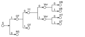
- FIG. 38A is a diagram showing an example of classification of each mode of MV derivation.
- FIG. 38B is a diagram showing an example of classification of each mode of MV derivation.
- FIG. 39 is a flowchart showing an example of inter prediction in the normal inter mode.
- FIG. 40 is a flowchart showing an example of inter prediction in the normal merge mode.
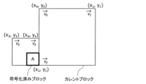
- FIG. 41 is a diagram for explaining an example of MV derivation processing in the normal merge mode.
- FIG. 42 is a diagram illustrating an example of MV derivation processing using HMVP (History-based Motion Vector Prediction/Predictor) mode.
- FIG. 43 is a flowchart showing an example of frame rate up conversion (FRUC).
- FIG. 44 is a diagram for explaining an example of pattern matching (bilateral matching) between two blocks along a motion trajectory.
- FIG. 45 is a diagram for explaining an example of pattern matching (template matching) between a template in a current picture and a block in a reference picture.
- FIG. 46A is a diagram for explaining an example of derivation of MVs on a sub-block basis in affine mode using two control points.
- FIG. 46B is a diagram for explaining an example of derivation of MVs on a sub-block basis in affine mode using three control points.
- FIG. 47A is a conceptual diagram for explaining an example of MV derivation of a control point in affine mode.
- FIG. 47B is a conceptual diagram for explaining an example of MV derivation of a control point in affine mode.
- FIG. 47C is a conceptual diagram for explaining an example of MV derivation of a control point in affine mode.
- FIG. 48A is a diagram for explaining an affine mode having two control points.
- FIG. 48B is a diagram for explaining an affine mode having three control points.
- FIG. 49A is a conceptual diagram for explaining an example of a method for deriving MVs of control points when the number of control points in an encoded block is different from that in a current block.
- FIG. 49B is a conceptual diagram for explaining another example of a method for deriving MVs of control points when the number of control points in an encoded block is different from that in a current block.
- FIG. 50 is a flowchart showing an example of processing in the affine merge mode.
- FIG. 51 is a flowchart showing an example of processing in the affine inter mode.
- FIG. 52A is a diagram for explaining generation of predicted images of two triangles.
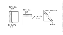
- FIG. 52B is a conceptual diagram showing an example of a first portion of a first partition, and a first and second sample set.
- FIG. 52C is a conceptual diagram showing a first portion of the first partition.
- FIG. 53 is a flow chart showing an example of the triangle mode.
- Figure 54 shows an example of ATMVP (Advanced Temporal Motion Vector Prediction/Predictor) mode in which MVs are derived on a subblock basis.
- Figure 55 is a diagram showing the relationship between merge mode and DMVR (dynamic motion vector refreshing).
- FIG. 56 is a conceptual diagram for explaining an example of a DMVR.
- FIG. 57 is a conceptual diagram for explaining another example of DMVR for determining MV.
- FIG. 58A is a diagram showing an example of motion estimation in a DMVR.
- FIG. 58B is a flowchart showing an example of motion estimation in a DMVR.
- FIG. 59 is a flowchart showing an example of generation of a predicted image.
- FIG. 60 is a flowchart showing another example of generation of a predicted image.
- FIG. 61 is a flowchart illustrating an example of a predictive image correction process using overlapped block motion compensation (OBMC).
- FIG. 62 is a conceptual diagram for explaining an example of a predictive image correction process using OBMC.
- FIG. 63 is a diagram for explaining a model assuming uniform linear motion.
- FIG. 64 is a flowchart showing an example of inter prediction according to BIO.
- FIG. 65 is a diagram showing an example of the configuration of an inter prediction unit that performs inter prediction according to BIO.
- Figure 66A is a diagram illustrating an example of a predicted image generation method using brightness correction processing by LIC (local illumination compensation).
- FIG. 66B is a flowchart showing an example of a predicted image generating method using luminance correction processing by LIC.
- FIG. 67 is a block diagram showing a configuration of a decoding device according to an embodiment.
- FIG. 68 is a block diagram showing an implementation example of a decoding device.
- FIG. 69 is a flowchart showing an example of the overall decoding process by the decoding device.
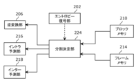
- FIG. 70 is a diagram showing the relationship between the division determination unit and other components.
- FIG. 71 is a block diagram showing an example of the configuration of an entropy decoding unit.
- FIG. 72 is a diagram showing the flow of CABAC in the entropy decoding unit.
- FIG. 73 is a block diagram showing an example of the configuration of the inverse quantization unit.
- FIG. 74 is a flowchart showing an example of inverse quantization by the inverse quantization unit.
- FIG. 75 is a flowchart showing an example of processing by the inverse conversion unit.
- FIG. 76 is a flowchart showing another example of the process by the inverse transform unit.
- FIG. 77 is a block diagram showing an example of the configuration of the loop filter unit.
- FIG. 78 is a flowchart showing an example of processing performed by a prediction unit of a decoding device.
- FIG. 79 is a flowchart showing another example of the process performed by the prediction unit of the decoding device.
- FIG. 80A is a flowchart showing a part of another example of processing performed in the prediction unit of the decoding device.
- FIG. 80A is a flowchart showing a part of another example of processing performed in the prediction unit of the decoding device.
- FIG. 80B is a flowchart showing the remaining part of another example of processing performed in the prediction unit of the decoding device.
- FIG. 81 is a diagram showing an example of processing by an intra prediction unit of a decoding device.
- FIG. 82 is a flowchart showing an example of MV derivation in a decoding device.
- FIG. 83 is a flowchart showing another example of MV derivation in a decoding device.
- FIG. 84 is a flowchart showing an example of inter prediction in normal inter mode in a decoding device.
- FIG. 85 is a flowchart showing an example of inter prediction in the normal merge mode in the decoding device.
- FIG. 86 is a flowchart showing an example of inter prediction in FRUC mode in the decoding device.
- FIG. 87 is a flowchart showing an example of inter prediction in affine merge mode in a decoding device.
- FIG. 88 is a flowchart showing an example of inter prediction in the affine inter mode in the decoding device.
- FIG. 89 is a flowchart showing an example of inter prediction in triangle mode in a decoding device.
- FIG. 90 is a flowchart showing an example of motion estimation by DMVR in a decoding device.
- FIG. 91 is a flowchart showing a detailed example of motion estimation by DMVR in the decoding device.
- FIG. 92 is a flowchart showing an example of generation of a predicted image in a decoding device.
- FIG. 93 is a flowchart showing another example of generation of a predicted image in the decoding device.
- FIG. 94 is a flowchart showing an example of correction of a predicted image by OBMC in a decoding device.
- FIG. 95 is a flowchart showing an example of correction of a predicted image by BIO in a decoding device.
- FIG. 96 is a flowchart showing an example of correction of a predicted image by LIC in a decoding device.
- FIG. 97 is a flowchart showing an example of operation regarding neural network filtering.
- FIG. 98 is a block diagram showing an example of a configuration related to neural network filtering.
- FIG. 99 is a block diagram showing an example of a configuration related to clipping processing.
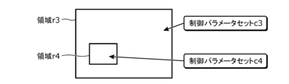
- FIG. 100 is a conceptual diagram showing an example of the layout of multiple regions in a picture.
- FIG. 100 is a conceptual diagram showing an example of the layout of multiple regions in a picture.
- FIG. 101 is a conceptual diagram showing another example of the layout of multiple regions in a picture.
- FIG. 102 is a conceptual diagram showing yet another example layout of multiple regions in a picture.
- FIG. 103 is a conceptual diagram showing an example of the operation of a neural network filter.
- FIG. 104 is a conceptual diagram showing another example of the operation of the neural network filter.
- FIG. 105 is a conceptual diagram showing an example of the signaling position of a control parameter set in a bit stream.
- FIG. 106 is a conceptual diagram showing another example of the signaling position of a control parameter set in a bit stream.
- FIG. 107 is a flowchart showing another example of operation regarding neural network filtering.
- FIG. 108 is a block diagram showing another example of a configuration relating to neural network filtering.
- FIG. 109 is a conceptual diagram showing a process for determining a control parameter set using a lookup table.
- FIG. 110 is a conceptual diagram showing an example of the signaling position of the first parameter in the bit stream.
- FIG. 111 is a conceptual diagram showing another example of the signaling position of the first parameter in the bit stream.
- FIG. 112 is a flowchart showing basic processing in the encoding operation according to the embodiment.
- FIG. 113 is a flowchart showing basic processing in a decoding operation according to an embodiment.
- FIG. 114 is a diagram showing the overall configuration of a content supply system that realizes a content distribution service.
- FIG. 115 is a diagram showing an example of a display screen of a web page.
- FIG. 116 is a diagram showing an example of a display screen of a web page.
- FIG. 117 is a diagram showing an example of a smartphone.
- FIG. 118 is a block diagram showing an example configuration of a smartphone.
- NNC Neural Network Coding
- a neural network filter is a filter based on a neural network, and corresponds to a neural network used as a filter.
- a neural network filter is also called a neural network-based filter or a neural network post-filter.
- Applying a neural network filter to a picture may improve the quality of the picture.
- a neural network filter is applied to a reconstructed picture.
- the neural network filter is not limited to being used as an out-loop filter to improve the quality of the picture to be displayed, but may also be used as an in-loop filter to improve the quality of the reference picture.
- Out-loop filters are also known as post-filters.
- In-loop filters are also called loop filters.
- the coding of neural network parameters that specify a neural network filter is being considered.
- the neural network parameters are parameters for setting the neural network used as a filter, and include parameters related to parameters such as weights in the neural network.
- a neural network filter which is a neural network-based filter, is trained to improve the image quality of the reconstructed picture.
- the neural network filter may be trained to make the reconstructed picture approximate the original picture.
- a reconstructed picture When a reconstructed picture is input to such a neural network filter, a reconstructed picture with improved image quality is output from the neural network filter.
- a neural network filter improves image quality.
- the decoder performs neural network filtering in an engine separate from the engine that performs processing such as DBF. That is, the decoded picture output by the decoding engine is provided to a neural network filtering engine and processed by the neural network filtering engine. Therefore, essentially, the neural network filter is set for each picture.
- the applicants therefore propose a specification in which the neural network filter itself is set on a picture-by-picture basis, but the information indicating the performance of the neural network filter is allowed to be switched on a region-by-region basis in the picture, thereby virtually switching the neural network filter on a region-by-region basis.
- the decoding device of Example 1 includes a memory and a circuit connected to the memory, which, in operation, decodes information from a bitstream for determining a control parameter set for neural network filtering to be applied to a picture for each of a plurality of regions in the picture, decodes the picture from the bitstream, and applies the neural network filtering to the picture, in which a single neural network filter is used for the picture, and the control parameter set determined based on the information is used for each of the plurality of regions.
- a single neural network filter is used, it may be possible to prevent the processing from becoming too complicated, and it may be possible to reduce the amount of code related to the neural network filter.
- the decoding device of Example 2 may also be the decoding device of Example 1, in which the picture to which the neural network filter processing has been applied is not used as a reference picture for decoding subsequent pictures in decoding order, but is used for display.
- This may allow display-specific neural network filtering to be applied to the picture, which may result in improved image quality.
- the decoding device of Example 3 may also be the decoding device of Example 1, in which the picture to which the neural network filter processing has been applied is used as a reference picture for decoding subsequent pictures in decoding order, and is used for display.
- the decoding device of Example 4 may be any one of the decoding devices of Examples 1 to 3, in which the control parameter set is a parameter for changing a filter parameter of the single neural network filter and includes a change intensity parameter that is a parameter indicating the magnitude of the change of the filter parameter, and in the neural network filter processing, the filter parameter is changed for each of the multiple regions based on the change intensity parameter.
- the decoding device of Example 5 may be any of the decoding devices of Examples 1 to 4, in which the control parameter set includes a threshold parameter indicating a range of a change in the value changed in the neural network filter process, and in the neural network filter process, the values of samples included in the picture are changed by the single neural network filter, and the change in the value of the sample is clipped to within the range based on the threshold parameter included in the control parameter set determined for each of the multiple regions.
- the decoding device of Example 6 may be any of the decoding devices of Examples 1 to 5, in which the information is decoded from a header area in the bitstream that includes at least one of SPS (Sequence Parameter Set), PPS (Picture Parameter Set), PH (Picture Header), SH (Slice Header), and SEI (Supplemental Enhancement Information).
- SPS Sequence Parameter Set
- PPS Picture Parameter Set
- PH Physical Header
- SH Selice Header
- SEI Supplemental Enhancement Information
- This may allow for efficient transmission of information for determining, for each region, a set of control parameters for the neural network filtering to be applied to the picture. Thus, it may be possible to efficiently apply the neural network filtering to the picture.
- the decoding device of Example 7 may be any of the decoding devices of Examples 1 to 6, and the circuit may decode the control parameter set from the bit stream as the information for each of the multiple regions.
- the decoding device of Example 8 may be any of the decoding devices of Examples 1 to 6, in which the circuit decodes an index assigned to each of the plurality of regions from the bit stream as the information, and the control parameter set is selected from a plurality of control parameter sets for each of the plurality of regions based on the index.
- the decoding device of Example 9 may be any of the decoding devices of Examples 1 to 6, in which the circuit decodes a quantization parameter indicating the degree of quantization for each of the multiple regions from the bit stream as the information, and the control parameter set is selected from multiple control parameter sets for each of the multiple regions based on the quantization parameter.
- the decoding device of Example 10 may be any of the decoding devices of Examples 1 to 6, in which the circuit further decodes from the bit stream, as the information, (i) a first parameter used to determine the control parameter set, and (ii) a quantization parameter indicating the degree of quantization for each of the multiple regions, and the control parameter set is determined using the first parameter and the quantization parameter.
- This may enable efficient determination of a control parameter set for each region based on a combination of the first parameter and the quantization parameter. It may also enable more flexible determination of a control parameter set for each region based on two parameters.
- the decoding device of Example 11 may be the decoding device of Example 10, in which the control parameter set is selected based on the quantization parameter from a plurality of control parameter sets registered in a lookup table selected from a plurality of lookup tables based on the first parameter.
- the decoding device of Example 12 may be the decoding device of Example 10 or 11, in which the first parameter is decoded from a header area in the bitstream that includes at least one of SPS (Sequence Parameter Set), PPS (Picture Parameter Set), PH (Picture Header), SH (Slice Header), and SEI (Supplemental Enhancement Information).
- SPS Sequence Parameter Set
- PPS Picture Parameter Set
- PH Physical Header
- SH Selice Header
- SEI Supplemental Enhancement Information
- it may allow the control parameter set for the neural network filtering to be efficiently determined, and it may allow the neural network filtering to be efficiently applied to the picture.
- the decoding device of Example 13 may be any of the decoding devices of Examples 1 to 6, in which the circuit decodes from a header region in the bitstream including at least one of SPS (Sequence Parameter Set), PPS (Picture Parameter Set), PH (Picture Header), SH (Slice Header), and SEI (Supplemental Enhancement Information) using an index assigned to each of the multiple regions or a quantization parameter indicating the degree of quantization for each of the multiple regions as the information, and the control parameter set is selected from multiple control parameter sets for each of the multiple regions based on the index or the quantization parameter.
- SPS Sequence Parameter Set
- PPS Physical Parameter Set
- PH Physical Header
- SH Selice Header
- SEI Supplemental Enhancement Information
- This may enable efficient transmission of the index or quantization parameters via the header region. It may also enable efficient determination of a control parameter set for each region from a plurality of control parameter sets based on the index or quantization parameters. This may therefore enable efficient application of neural network filtering to pictures. It may also enable a reduction in the amount of coding required for determining the control parameter set for each region.
- the decoding device of Example 14 may be any of the decoding devices of Examples 9 to 12, in which the multiple regions are multiple CUs (Coding Units), respectively, and the control parameter set is determined based on the quantization parameters for each of the multiple CUs.
- the multiple regions are multiple CUs (Coding Units), respectively, and the control parameter set is determined based on the quantization parameters for each of the multiple CUs.
- the encoding device of Example 15 also includes a memory and a circuit connected to the memory, which, in operation, encodes information for determining a control parameter set for a neural network filter process to be applied to a picture for each of a plurality of regions in the picture into a bitstream, encodes the picture into the bitstream, and the neural network filter process uses a single neural network filter for the picture, and uses the control parameter set determined based on the information for each of the plurality of regions.
- a single neural network filter is used, it may be possible to prevent the processing from becoming too complicated, and it may be possible to reduce the amount of code related to the neural network filter.
- the encoding device of Example 16 may be the encoding device of Example 15, in which the circuitry further applies the neural network filter processing to the picture, and the picture to which the neural network filter processing has been applied is used as a reference picture for encoding a subsequent picture in the encoding order.
- the encoding device of Example 17 may be the encoding device of Example 15 or 16, in which the control parameter set is a parameter for changing a filter parameter of the single neural network filter and includes a change intensity parameter that is a parameter indicating the magnitude of the change of the filter parameter, and in the neural network filter processing, the filter parameter is changed for each of the multiple regions based on the change intensity parameter.
- the encoding device of Example 18 may be any of the encoding devices of Examples 15 to 17, in which the control parameter set includes a threshold parameter indicating a range of a change in the value changed in the neural network filter process, and in the neural network filter process, the values of samples included in the picture are changed by the single neural network filter, and the change in the value of the sample is clipped to within the range based on the threshold parameter included in the control parameter set determined for each of the multiple regions.
- the encoding device of Example 19 may be any of the encoding devices of Examples 15 to 18, in which the information is encoded in a header area in the bitstream that includes at least one of SPS (Sequence Parameter Set), PPS (Picture Parameter Set), PH (Picture Header), SH (Slice Header), and SEI (Supplemental Enhancement Information).
- SPS Sequence Parameter Set
- PPS Picture Parameter Set
- PH Physical Header
- SH Selice Header
- SEI Supplemental Enhancement Information
- This may allow for efficient transmission of information for determining, for each region, a set of control parameters for the neural network filtering to be applied to the picture. Thus, it may be possible to efficiently apply the neural network filtering to the picture.
- the encoding device of Example 20 may be any of the encoding devices of Examples 15 to 19, and the circuit may be an encoding device that encodes the control parameter set as the information into the bit stream for each of the multiple regions.
- the encoding device of Example 21 may be any of the encoding devices of Examples 15 to 19, in which the circuit encodes an index assigned to each of the multiple regions as the information into the bit stream, and the control parameter set is selected from multiple control parameter sets for each of the multiple regions based on the index.
- the encoding device of Example 22 may be any of the encoding devices of Examples 15 to 19, in which the circuit encodes a quantization parameter indicating the degree of quantization for each of the multiple regions into the bit stream as the information, and the control parameter set is selected from multiple control parameter sets for each of the multiple regions based on the quantization parameter.
- the encoding device of Example 23 may be any of the encoding devices of Examples 15 to 19, in which the circuit further encodes, as the information, (i) a first parameter used to determine the control parameter set, and (ii) a quantization parameter indicating the degree of quantization for each of the multiple regions, into the bit stream, and the control parameter set is determined using the first parameter and the quantization parameter.
- This may enable efficient determination of a control parameter set for each region based on a combination of the first parameter and the quantization parameter. It may also enable more flexible determination of a control parameter set for each region based on two parameters.
- the encoding device of Example 24 may be the encoding device of Example 23, in which the control parameter set is selected based on the quantization parameter from a plurality of control parameter sets registered in a lookup table selected from a plurality of lookup tables based on the first parameter.
- the encoding device of Example 25 may be the encoding device of Example 23 or 24, in which the first parameter is encoded in a header area in the bitstream that includes at least one of SPS (Sequence Parameter Set), PPS (Picture Parameter Set), PH (Picture Header), SH (Slice Header), and SEI (Supplemental Enhancement Information).
- SPS Sequence Parameter Set
- PPS Picture Parameter Set
- PH Physical Header
- SH Selice Header
- SEI Supplemental Enhancement Information
- it may allow the control parameter set for the neural network filtering to be efficiently determined, and the neural network filtering to be efficiently applied to the picture.
- the encoding device of Example 26 may be the encoding device of any one of Examples 15 to 19, in which the circuit encodes, as the information, an index assigned to each of the multiple regions or a quantization parameter indicating the degree of quantization for each of the multiple regions, into a header region in the bitstream that includes at least one of SPS (Sequence Parameter Set), PPS (Picture Parameter Set), PH (Picture Header), SH (Slice Header), and SEI (Supplemental Enhancement Information), and the control parameter set is selected from multiple control parameter sets for each of the multiple regions based on the index or the quantization parameter.
- SPS Sequence Parameter Set
- PPS Physical Parameter Set
- PH Physical Header
- SH Selice Header
- SEI Supplemental Enhancement Information
- This may enable efficient transmission of the index or quantization parameters via the header region. It may also enable efficient determination of a control parameter set for each region from a plurality of control parameter sets based on the index or quantization parameters. This may therefore enable efficient application of neural network filtering to pictures. It may also enable a reduction in the amount of coding required for determining the control parameter set for each region.
- the encoding device of Example 27 may be any of the encoding devices of Examples 22 to 25, in which the multiple regions are multiple CUs (Coding Units), respectively, and the control parameter set is determined based on the quantization parameters for each of the multiple CUs.
- the multiple regions are multiple CUs (Coding Units), respectively, and the control parameter set is determined based on the quantization parameters for each of the multiple CUs.
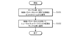
- the decoding method of Example 28 further includes decoding information from a bitstream for determining a control parameter set for neural network filtering to be applied to a picture for each of a plurality of regions in the picture, decoding the picture from the bitstream, and applying the neural network filtering to the picture, in which a single neural network filter is used for the picture in the neural network filtering, and the control parameter set determined based on the information is used for each of the plurality of regions.
- a single neural network filter is used, it may be possible to prevent the processing from becoming too complicated, and it may be possible to reduce the amount of code related to the neural network filter.
- the encoding method of Example 29 is an encoding method that encodes information for determining a control parameter set for a neural network filter process to be applied to a picture for each of a plurality of regions in the picture into a bitstream, encodes the picture into the bitstream, and in the neural network filter process, a single neural network filter is used for the picture, and the control parameter set determined based on the information is used for each of the plurality of regions.
- a single neural network filter is used, it may be possible to prevent the processing from becoming too complicated, and it may be possible to reduce the amount of code related to the neural network filter.
- the decoding device of Example 30 also includes an input unit, an entropy decoding unit, an inverse quantization unit, an inverse transform unit, an intra prediction unit, an inter prediction unit, a loop filter unit, and an output unit.
- the input unit receives an encoded bitstream.
- the entropy decoding unit applies variable length decoding to the encoded bitstream to derive quantization coefficients.
- the inverse quantization unit inversely quantizes the quantization coefficients to derive transform coefficients.
- the inverse transform unit inversely transforms the transform coefficients to derive prediction errors.
- the intra prediction unit generates a prediction signal of a current block included in the current picture using reference pixels included in the current picture.
- the inter prediction unit generates a prediction signal of a current block included in the current picture using a reference block included in a reference picture other than the current picture.
- the loop filter unit applies a filter to a reconstructed block of the current block included in the current picture. Then, the current picture is output from the output unit.
- the entropy decoding unit decodes information from the bitstream for determining a control parameter set for neural network filtering to be applied to a picture for each of a plurality of regions in the picture, decodes the picture from the bitstream, and applies the neural network filtering to the picture, where a single neural network filter is used for the picture in the neural network filtering, and the control parameter set determined based on the information is used for each of the plurality of regions.
- the encoding device of Example 31 also includes an input unit, a division unit, an intra prediction unit, an inter prediction unit, a loop filter unit, a transformation unit, a quantization unit, an entropy encoding unit, and an output unit.
- the current picture is input to the input unit.
- the division unit divides the current picture into a plurality of blocks.
- the intra prediction unit generates a prediction signal of a current block included in the current picture using reference pixels included in the current picture.
- the inter prediction unit generates a prediction signal of a current block included in the current picture using a reference block included in a reference picture other than the current picture.
- the loop filter unit applies a filter to a reconstructed block of the current block included in the current picture.
- the transform unit transforms a prediction error between an original signal of a current block included in the current picture and a prediction signal generated by the intra prediction unit or the inter prediction unit to generate transform coefficients.
- the quantization unit quantizes the transform coefficients to generate quantized coefficients.
- the entropy coding unit applies variable length coding to the quantized coefficients to generate an encoded bitstream. Then, the output unit outputs the encoded bitstream including the quantized coefficients to which variable length coding has been applied and control information.
- the entropy coding unit encodes information for determining a control parameter set for a neural network filter process to be applied to a picture for each of a plurality of regions in the picture into a bitstream, and encodes the picture into the bitstream, such that in the neural network filter process, a single neural network filter is used for the picture, and the control parameter set determined based on the information is used for each of the plurality of regions.
- each term may be defined as follows:
- Image A unit of data composed of a set of pixels, which consists of pictures or blocks smaller than a picture, and includes both moving images and still images.
- Picture A processing unit of an image composed of a set of pixels. It is also called a frame or field.
- Block A processing unit of a set containing a specific number of pixels, and can be named in any way, as shown in the following examples.
- any shape can be used, including, for example, a rectangle made of M ⁇ N pixels, a square made of M ⁇ M pixels, a triangle, a circle, and other shapes.
- a pixel/sample is the smallest unit point that constitutes an image, and includes not only pixels at integer positions but also pixels at decimal positions that are generated based on pixels at integer positions.
- Pixel Value/Sample Value A value inherent to a pixel, including not only brightness value, color difference value, and RGB gradation, but also depth value or the binary values 0 and 1.
- flags may be multi-bit, for example, parameters or indexes of two or more bits.
- flags may be multi-valued using other base numbers as well as two values using binary numbers.
- Signal Something that is symbolized or coded to transmit information, including discrete digital signals as well as analog signals that take continuous values.
- a stream/Bit Stream A data string of digital data or a flow of digital data.
- a stream/bit stream may be a single stream or may be divided into multiple layers and composed of multiple streams. It also includes cases where the data is transmitted by serial communication over a single transmission line, as well as cases where the data is transmitted by packet communication over multiple transmission lines.
- Color difference It is an adjective, denoted by the symbols Cb and Cr, that specifies that a sample array or a single sample represents one of two colour difference signals associated with a primary colour.
- the term chrominance can also be used.
- Luminance It is an adjective, denoted by the symbol or subscript Y or L, that specifies that the sample array or a single sample represents a monochrome signal associated with a primary color. Instead of the term luma, the term luminance can also be used.
- an encoding device and a decoding device are described.
- the embodiments are examples of encoding devices and decoding devices to which the processes and/or configurations described in each aspect of the present disclosure can be applied.
- the processes and/or configurations can also be implemented in encoding devices and decoding devices that are different from the embodiments.
- any of the following may be implemented.
- any change may be made to the functions or processes performed by some of the multiple components of the encoding device or decoding device, such as adding, replacing, or deleting a function or process.
- any function or process may be replaced or combined with another function or process described in any of the aspects of the present disclosure.
- Some of the components among the multiple components constituting the encoding device or decoding device of the embodiment may be combined with components described in any of the aspects of the present disclosure, may be combined with components having some of the functions described in any of the aspects of the present disclosure, or may be combined with components that perform some of the processing performed by the components described in any of the aspects of the present disclosure.
- a component having part of the functionality of the encoding device or decoding device of an embodiment, or a component performing part of the processing of the encoding device or decoding device of an embodiment may be combined or replaced with a component described in any of the aspects of the present disclosure, a component having part of the functionality described in any of the aspects of the present disclosure, or a component performing part of the processing described in any of the aspects of the present disclosure.
- any of the multiple processes included in the method may be replaced or combined with any of the processes described in any of the aspects of the present disclosure or any similar processes.
- FIG. 1 is a schematic diagram showing an example of the configuration of a transmission system according to the present embodiment.
- the transmission system Trs is a system that transmits a stream generated by encoding an image and decodes the transmitted stream.
- Such a transmission system Trs includes, for example, an encoding device 100, a network Nw, and a decoding device 200, as shown in FIG. 1.
- An image is input to the encoding device 100.
- the encoding device 100 generates a stream by encoding the input image, and outputs the stream to the network Nw.
- the stream includes, for example, the encoded image and control information for decoding the encoded image.
- the image is compressed by this encoding.
- the original image before encoding that is input to the encoding device 100 is also called an original image, an original signal, or an original sample.
- the image may be a video image or a still image.
- An image is a higher-level concept than a sequence, a picture, or a block, and is not limited in spatial and temporal domains unless otherwise specified.
- An image is composed of an array of pixels or pixel values, and a signal representing the image, or the pixel values, is also called a sample.
- a stream may be called a bit stream, an encoded bit stream, a compressed bit stream, or an encoded signal.
- the encoding device may be called an image encoding device or a video encoding device, and the encoding method by the encoding device 100 may be called an encoding method, an image encoding method, or a video encoding method.
- the network Nw transmits the stream generated by the encoding device 100 to the decoding device 200.
- the network Nw may be the Internet, a wide area network (WAN), a small-scale network (LAN), or a combination of these.
- the network Nw is not necessarily limited to a two-way communication network, and may be a one-way communication network that transmits broadcast waves such as terrestrial digital broadcasting or satellite broadcasting.
- the network Nw may also be replaced by a storage medium that records streams, such as a DVD (Digital Versatile Disc) or a BD (Blu-Ray Disc (registered trademark)).
- the decoding device 200 generates a decoded image, which is, for example, an uncompressed image, by decoding the stream transmitted by the network Nw. For example, the decoding device decodes the stream according to a decoding method that corresponds to the encoding method used by the encoding device 100.
- the decoding device may be called an image decoding device or a video decoding device, and the decoding method performed by the decoding device 200 may be called a decoding method, an image decoding method, or a video decoding method.
- [Data Structure] 2 is a diagram showing an example of a hierarchical structure of data in a stream.
- the stream includes, for example, a video sequence.
- the video sequence includes a video parameter set (VPS), a sequence parameter set (SPS), a picture parameter set (PPS), supplemental enhancement information (SEI), and a plurality of pictures.
- VPS video parameter set
- SPS sequence parameter set
- PPS picture parameter set
- SEI Supplemental Enhancement Information
- the VPS For a video that is composed of multiple layers, the VPS includes coding parameters that are common to the multiple layers, and coding parameters related to the multiple layers or individual layers included in the video.
- the SPS includes parameters used for the sequence, i.e., the encoding parameters referenced by the decoding device 200 to decode the sequence.
- the encoding parameters may indicate the width or height of a picture. Note that there may be multiple SPSs.
- the PPS includes parameters used for a picture, i.e., encoding parameters referenced by the decoding device 200 to decode each picture in a sequence.
- the encoding parameters may include a reference value of the quantization width used in decoding the picture and a flag indicating the application of weighted prediction.
- the SPS and PPS may simply be referred to as parameter sets.
- a picture may include a picture header and one or more slices, as shown in FIG. 2B.
- the picture header includes coding parameters that are referenced by the decoding device 200 to decode the one or more slices.
- a slice includes a slice header and one or more bricks.
- the slice header includes coding parameters that are referenced by the decoding device 200 to decode the one or more bricks.
- a brick contains one or more coding tree units (CTUs), as shown in (d) of Figure 2.
- CTUs coding tree units
- a picture may not contain slices, but may instead contain tile groups.
- a tile group contains one or more tiles.
- a brick may contain slices.
- a CTU is also called a superblock or a basic division unit.
- Such a CTU includes a CTU header and one or more coding units (CUs), as shown in FIG. 2(e).
- the CTU header includes coding parameters that are referenced by the decoding device 200 to decode one or more CUs.
- a CU may be divided into multiple smaller CUs. As shown in FIG. 2(f), a CU includes a CU header, prediction information, and residual coefficient information.
- the prediction information is information for predicting the CU
- the residual coefficient information is information indicating a prediction residual, which will be described later.
- a CU is basically the same as a PU (Prediction Unit) and a TU (Transform Unit), but may include multiple TUs smaller than the CU, for example, in an SBT, which will be described later.
- a CU may be processed for each VPDU (Virtual Pipeline Decoding Unit) that constitutes the CU.
- a VPDU is a fixed unit that can be processed in one stage, for example, when performing pipeline processing in hardware.
- a picture that is currently the subject of processing performed by a device such as the encoding device 100 or the decoding device 200 is called a current picture. If the processing is encoding, the current picture is synonymous with a picture to be encoded, and if the processing is decoding, the current picture is synonymous with a picture to be decoded.
- a block, such as a CU or CU, that is currently the subject of processing performed by a device such as the encoding device 100 or the decoding device 200 is called a current block. If the processing is encoding, the current block is synonymous with a block to be encoded, and if the processing is decoding, the current block is synonymous with a block to be decoded.
- Picture Composition Slices/Tiles
- the pictures may be organized into slices or tiles.
- a slice is the basic coding unit that makes up a picture.
- a picture for example, is composed of one or more slices.
- a slice is also composed of one or more consecutive CTUs.
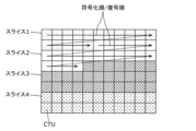
- FIG. 3 is a diagram showing an example of the configuration of a slice.
- a picture includes 11 ⁇ 8 CTUs and is divided into four slices (slices 1-4).
- Slice 1 includes, for example, 16 CTUs
- slice 2 includes, for example, 21 CTUs
- slice 3 includes, for example, 29 CTUs
- slice 4 includes, for example, 22 CTUs.
- each CTU in a picture belongs to one of the slices.
- the shape of a slice is obtained by dividing the picture horizontally.
- the boundary of a slice does not need to be the edge of the screen, and may be any boundary of the CTUs in the screen.
- the processing order (encoding order or decoding order) of the CTUs in a slice is, for example, raster scan order.
- a slice includes a slice header and encoded data.
- the slice header may describe the characteristics of the slice, such as the CTU address at the beginning of the slice and the slice type.
- a tile is a rectangular area that makes up a picture.
- Each tile may be assigned a number called a TileId in raster scan order.
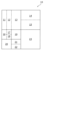
- FIG. 4 is a diagram showing an example of a tile configuration.
- a picture includes 11 ⁇ 8 CTUs and is divided into four rectangular tiles (tiles 1-4).
- the processing order of the CTUs is changed compared to when tiles are not used.
- the multiple CTUs in a picture are processed, for example, in raster scan order.
- the processing order of the multiple CTUs included in tile 1 is from the left end of the first column of tile 1 to the right end of the first column of tile 1, and then from the left end of the second column of tile 1 to the right end of the second column of tile 1.
- one tile may contain one or more slices, and one slice may contain one or more tiles.
- a picture may be composed of tile sets.
- a tile set may include one or more tile groups, and may include one or more tiles.
- a picture may be composed of only one of tile sets, tile groups, and tiles. For example, the order in which multiple tiles for each tile set are scanned in raster order is set as the basic coding order for the tiles. A collection of one or more tiles in consecutive basic coding orders within each tile set is set as a tile group.
- Such a picture may be composed by the division unit 102 (see FIG. 7), which will be described later.
- [Scalable Coding] 5 and 6 are diagrams showing an example of a scalable stream structure.
- the encoding device 100 may generate a temporally/spatially scalable stream by encoding each of a plurality of pictures separately into one of a plurality of layers.
- the encoding device 100 realizes scalability in which an enhancement layer exists above a base layer by encoding pictures for each layer.
- Such encoding of each picture is called scalable encoding.
- This allows the decoding device 200 to switch the image quality of the image displayed by decoding the stream.
- the decoding device 200 determines up to which layer to decode depending on an internal factor, namely its own performance, and an external factor, such as the state of the communication band.
- the decoding device 200 can freely switch and decode the same content between low-resolution content and high-resolution content.
- a user of the stream watches the video of the stream halfway using a smartphone while on the move, and watches the rest of the video using a device such as an Internet TV after returning home.
- the above-mentioned smartphone and device each incorporate a decoding device 200 with the same or different performance. In this case, if the device decodes up to the upper layers of the stream, the user can watch high-quality video after returning home. This eliminates the need for the encoding device 100 to generate multiple streams with the same content but different image quality, thereby reducing the processing load.
- the enhancement layer may include meta-information based on statistical information of the image, etc.
- the decoding device 200 may generate a high-quality moving image by super-resolving the pictures of the base layer based on the meta-information.
- Super-resolution may mean either an improvement in the signal-to-noise (SN) ratio at the same resolution, or an increase in resolution.
- the meta-information may include information for specifying linear or nonlinear filter coefficients to be used in the super-resolution process, or information for specifying parameter values in the filter process, machine learning, or least squares calculation to be used in the super-resolution process.
- the picture may be divided into tiles or the like according to the meaning of each object in the picture.
- the decoding device 200 may decode only a part of the picture by selecting a tile to be decoded.
- the attribute of the object person, car, ball, etc.
- the position in the picture may be stored as meta information.
- the decoding device 200 can identify the position of the desired object based on the meta information and determine the tile containing the object. For example, as shown in FIG. 6, the meta information is stored using a data storage structure different from the image data, such as SEI in HEVC. This meta information indicates, for example, the position, size, or color of the main object.
- meta information may be stored in units consisting of multiple pictures, such as streams, sequences, or random access units. This allows the decoding device 200 to obtain the time at which a specific person appears in a video, and by using this time and picture-by-picture information, it is possible to identify the picture in which an object exists and the position of the object within that picture.
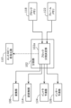
- Fig. 7 is a block diagram showing an example of the configuration of the encoding device 100 according to an embodiment.
- the encoding device 100 encodes an image on a block-by-block basis.
- the encoding device 100 is a device that encodes an image on a block-by-block basis, and includes a division unit 102, a subtraction unit 104, a transformation unit 106, a quantization unit 108, an entropy encoding unit 110, an inverse quantization unit 112, an inverse transformation unit 114, an addition unit 116, a block memory 118, a loop filter unit 120, a frame memory 122, an intra prediction unit 124, an inter prediction unit 126, a prediction control unit 128, and a prediction parameter generation unit 130.
- each of the intra prediction unit 124 and the inter prediction unit 126 is configured as part of a prediction processing unit.
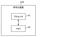
- FIG. 8 is a block diagram showing an implementation example of the encoding device 100.
- the encoding device 100 includes a processor a1 and a memory a2.
- the encoding device 100 shown in Fig. 7 are implemented by the processor a1 and the memory a2 shown in Fig. 8.
- Processor a1 is a circuit that performs information processing and is a circuit that can access memory a2.
- processor a1 is a dedicated or general-purpose electronic circuit that encodes images.
- Processor a1 may be a processor such as a CPU.
- Processor a1 may also be a collection of multiple electronic circuits.
- processor a1 may also fulfill the roles of multiple components of the encoding device 100 shown in FIG. 7, excluding the components for storing information.
- Memory a2 is a dedicated or general-purpose memory in which information for processor a1 to encode an image is stored.
- Memory a2 may be an electronic circuit and may be connected to processor a1.
- Memory a2 may also be included in processor a1.
- Memory a2 may also be a collection of multiple electronic circuits.
- Memory a2 may also be a magnetic disk or optical disk, etc., and may be expressed as storage or recording medium, etc.
- Memory a2 may also be a non-volatile memory or a volatile memory.
- the memory a2 may store an image to be encoded, or a stream corresponding to the encoded image. Also, the memory a2 may store a program for the processor a1 to encode the image.
- the memory a2 may play the role of a component for storing information among the multiple components of the encoding device 100 shown in FIG. 7. Specifically, the memory a2 may play the role of the block memory 118 and the frame memory 122 shown in FIG. 7. More specifically, the memory a2 may store a reconstructed image (specifically, a reconstructed block or a reconstructed picture, etc.).
- FIG. 9 is a flowchart showing an example of the overall encoding process performed by the encoding device 100.
- the division unit 102 of the encoding device 100 divides the picture included in the original image into multiple fixed-size blocks (128 x 128 pixels) (step Sa_1). Then, the division unit 102 selects a division pattern for the fixed-size blocks (step Sa_2). In other words, the division unit 102 further divides the fixed-size block into multiple blocks that constitute the selected division pattern. Then, the encoding device 100 performs the processes of steps Sa_3 to Sa_9 for each of the multiple blocks.
- the prediction processing unit which is composed of the intra prediction unit 124 and the inter prediction unit 126, and the prediction control unit 128 generate a predicted image of the current block (step Sa_3).
- the predicted image is also called a predicted signal, a predicted block, or a predicted sample.
- the subtraction unit 104 generates the difference between the current block and the predicted image as a prediction residual (step Sa_4).
- the prediction residual is also called a prediction error.
- the transform unit 106 and the quantization unit 108 perform transform and quantization on the predicted image to generate multiple quantization coefficients (step Sa_5).
- the entropy coding unit 110 generates a stream by performing coding (specifically, entropy coding) on the multiple quantization coefficients and the prediction parameters related to the generation of a predicted image (step Sa_6).
- the inverse quantization unit 112 and the inverse transform unit 114 perform inverse quantization and inverse transform on the multiple quantized coefficients to restore the prediction residual (step Sa_7).
- the adder 116 reconstructs the current block by adding the predicted image to the restored prediction residual (step Sa_8). This generates a reconstructed image.
- the reconstructed image is also called a reconstructed block, and in particular, the reconstructed image generated by the encoding device 100 is also called a locally decoded block or a locally decoded image.
- the loop filter unit 120 performs filtering on the reconstructed image as necessary (step Sa_9).
- the encoding device 100 determines whether encoding of the entire picture is complete (step Sa_10), and if it determines that encoding is not complete (No in step Sa_10), it repeats the process from step Sa_2.
- the encoding device 100 selects one division pattern for fixed-size blocks and encodes each block according to that division pattern, but it may also encode each block according to each of multiple division patterns. In this case, the encoding device 100 may evaluate the cost for each of the multiple division patterns and select, for example, the stream obtained by encoding according to the division pattern with the smallest cost as the final stream to be output.
- steps Sa_1 to Sa_10 may be performed sequentially by the encoding device 100, or some of the processing may be performed in parallel, or the order may be changed.
- the coding process performed by such a coding device 100 is hybrid coding that uses predictive coding and transform coding. Furthermore, predictive coding is performed by a coding loop consisting of the subtraction unit 104, transform unit 106, quantization unit 108, inverse quantization unit 112, inverse transform unit 114, addition unit 116, loop filter unit 120, block memory 118, frame memory 122, intra prediction unit 124, inter prediction unit 126, and prediction control unit 128. In other words, the prediction processing unit consisting of the intra prediction unit 124 and inter prediction unit 126 forms part of the coding loop.
- the division unit 102 divides each picture included in the original image into a plurality of blocks, and outputs each block to the subtraction unit 104.
- the division unit 102 first divides the picture into blocks of a fixed size (e.g., 128x128 pixels).
- the fixed-size blocks may be called coding tree units (CTUs).
- the division unit 102 divides each of the fixed-size blocks into blocks of a variable size (e.g., 64x64 pixels or less) based on, for example, recursive quadtree and/or binary tree block division. That is, the division unit 102 selects a division pattern.
- variable-size blocks may be called coding units (CUs), prediction units (PUs), or transform units (TUs). Note that in various implementation examples, CUs, PUs, and TUs do not need to be distinguished, and some or all of the blocks in a picture may be the processing units of CUs, PUs, or TUs.
- FIG. 10 is a diagram showing an example of block division in an embodiment.
- solid lines represent block boundaries based on quadtree block division
- dashed lines represent block boundaries based on binary tree block division.
- block 10 is a square block of 128x128 pixels. This block 10 is first divided into four square blocks of 64x64 pixels (quadtree block division).
- the upper left 64x64 pixel square block is further divided vertically into two rectangular blocks of 32x64 pixels each, and the left 32x64 pixel rectangular block is further divided vertically into two rectangular blocks of 16x64 pixels each (binary tree block division).
- the upper left 64x64 pixel square block is divided into two 16x64 pixel rectangular blocks 11 and 12, and a 32x64 pixel rectangular block 13.
- the 64x64 pixel square block in the upper right corner is divided horizontally into two rectangular blocks 14 and 15, each of 64x32 pixels (binary tree block division).
- the lower left square block of 64x64 pixels is divided into four square blocks of 32x32 pixels each (quadtree block division). Of the four square blocks of 32x32 pixels each, the upper left and lower right blocks are further divided.
- the upper left square block of 32x32 pixels is divided vertically into two rectangular blocks of 16x32 pixels each, and the right rectangular block of 16x32 pixels is further divided horizontally into two square blocks of 16x16 pixels each (binary tree block division).
- the lower right square block of 32x32 pixels is divided horizontally into two rectangular blocks of 32x16 pixels each (binary tree block division).
- the lower left square block of 64x64 pixels is divided into a rectangular block 16 of 16x32 pixels, two square blocks 17 and 18 each of 16x16 pixels, two square blocks 19 and 20 each of 32x32 pixels, and two rectangular blocks 21 and 22 each of 32x16 pixels.
- block 10 is divided into 13 variable-sized blocks 11 to 23 based on recursive quad-tree and binary-tree block division.
- This type of division is sometimes called QTBT (quad-tree plus binary tree) division.
- one block is divided into four or two blocks (quadtree or binary tree block division), but the division is not limited to this.
- one block may be divided into three blocks (ternary tree block division). Divisions that include such ternary tree block division are sometimes called MBT (multi type tree) divisions.
- MBT multi type tree
- FIG. 11 is a diagram showing an example of the configuration of the division unit 102.
- the division unit 102 may include a block division determination unit 102a.
- the block division determination unit 102a may perform the following processing.
- the block division determination unit 102a collects block information from the block memory 118 or the frame memory 122, and determines the above-mentioned division pattern based on the block information.
- the division unit 102 divides the original image according to the division pattern, and outputs one or more blocks obtained by the division to the subtraction unit 104.
- the block division determination unit 102a also outputs, for example, parameters indicating the above-mentioned division pattern to the transformation unit 106, the inverse transformation unit 114, the intra prediction unit 124, the inter prediction unit 126, and the entropy coding unit 110.
- the transformation unit 106 may transform the prediction residual based on the parameters, and the intra prediction unit 124 and the inter prediction unit 126 may generate a predicted image based on the parameters.
- the entropy coding unit 110 may also perform entropy coding on the parameters.
- parameters related to the splitting pattern may be written to the stream as follows:
- FIG. 12 shows examples of division patterns.
- the division patterns include, for example, 4-way division (QT) in which a block is divided into two parts in each of the horizontal and vertical directions, 3-way division (HT or VT) in which a block is divided in the same direction in a 1:2:1 ratio, 2-way division (HB or VB) in which a block is divided in the same direction in a 1:1 ratio, and no division (NS).
- QT 4-way division
- HT or VT 3-way division
- HB or VB 2-way division
- NS no division
- the division pattern does not have a block division direction, but in the case of division into two or three, the division pattern has division direction information.
- FIG. 13A and 13B are diagrams showing an example of a syntax tree of a splitting pattern.
- S Split flag
- QT QT flag
- TT TT flag or BT: BT flag
- BT flag BT flag
- the split direction Ver: Vertical flag or Hor: Horizontal flag
- the information is arranged in the order S, QT, TT, Ver, but the information may also be arranged in the order S, QT, Ver, BT. That is, in the example of FIG. 13B, first there is information indicating whether or not to split (S: Split flag), then there is information indicating whether or not to split into four (QT: QT flag). Next there is information indicating the split direction (Ver: Vertical flag or Hor: Horizontal flag), and finally there is information indicating whether to split into two or three (BT: BT flag or TT: TT flag).
- division patterns described here are just examples, and division patterns other than those described may be used, or only some of the division patterns described may be used.
- the subtraction unit 104 subtracts the predicted image (the predicted image input from the prediction control unit 128) from the original image for each block input from the division unit 102. That is, the subtraction unit 104 calculates a prediction residual of the current block. Then, the subtraction unit 104 outputs the calculated prediction residual to the conversion unit 106.
- the original image is an input signal to the encoding device 100, and is, for example, a signal representing the image of each picture that constitutes a moving image (e.g., a luma signal and two chroma signals).
- a signal representing the image of each picture that constitutes a moving image e.g., a luma signal and two chroma signals.
- the transform unit 106 transforms the spatial domain prediction residual into a transform coefficient in the frequency domain, and outputs the transform coefficient to the quantization unit 108. Specifically, the transform unit 106 performs a predetermined discrete cosine transform (DCT) or discrete sine transform (DST) on the spatial domain prediction residual, for example.
- DCT discrete cosine transform
- DST discrete sine transform
- the transform unit 106 may adaptively select a transform type from among a plurality of transform types, and convert the prediction residual into a transform coefficient using a transform basis function corresponding to the selected transform type.
- a transform may be called an explicit multiple core transform (EMT) or an adaptive multiple transform (AMT).
- EMT explicit multiple core transform
- AMT adaptive multiple transform
- the transform basis function may also be simply called a basis.
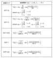
- the multiple transform types include, for example, DCT-II, DCT-V, DCT-VIII, DST-I, and DST-VII. These transform types may be written as DCT2, DCT5, DCT8, DST1, and DST7, respectively.
- FIG. 14 is a table showing the transform basis functions corresponding to each transform type. In FIG. 14, N indicates the number of input pixels. The selection of a transform type from among these multiple transform types may depend, for example, on the type of prediction (such as intra prediction and inter prediction) or on the intra prediction mode.
- EMT flag or an AMT flag Information indicating whether such EMT or AMT is applied (e.g., called an EMT flag or an AMT flag) and information indicating the selected transformation type are typically signaled at the CU level. Note that signaling of this information does not need to be limited to the CU level, but may also be at other levels (e.g., sequence level, picture level, slice level, brick level, or CTU level).
- the transform unit 106 may also retransform the transform coefficients (i.e., the transform results). Such retransformation may be called adaptive secondary transform (AST) or non-separable secondary transform (NSST). For example, the transform unit 106 performs retransformation for each subblock (e.g., a subblock of 4x4 pixels) included in a block of transform coefficients corresponding to intra-prediction residuals.
- AST adaptive secondary transform
- NSST non-separable secondary transform
- the transform unit 106 performs retransformation for each subblock (e.g., a subblock of 4x4 pixels) included in a block of transform coefficients corresponding to intra-prediction residuals.
- Information indicating whether or not to apply NSST and information regarding the transform matrix used for NSST are usually signaled at the CU level. Note that the signaling of these pieces of information does not need to be limited to the CU level, and may be at other levels (e.g., sequence level, picture level, slice level
- the conversion unit 106 may apply a separable conversion and a non-separable conversion.
- a separable conversion is a method in which the conversion is performed multiple times by separating the input into directions for the number of dimensions
- a non-separable conversion is a method in which, when the input is multidimensional, two or more dimensions are combined and treated as one dimension, and the conversion is performed collectively.
- one example of a non-separable transformation would be one in which, if the input is a 4x4 pixel block, it is treated as a single array with 16 elements, and a transformation process is performed on that array using a 16x16 transformation matrix.
- a 4x4 pixel input block may be treated as a single array with 16 elements, and then a transformation (Hypercube Givens Transform) may be performed on the array by performing Givens rotation multiple times.
- a transformation Hypercube Givens Transform
- the conversion unit 106 In the conversion performed by the conversion unit 106, it is also possible to switch the type of conversion basis function used to convert to the frequency domain depending on the area within the CU.
- One example is SVT (Spatially Varying Transform).
- FIG. 15 shows an example of an SVT.
- a CU is divided into two equal parts in the horizontal or vertical direction, and only one of the regions is transformed into the frequency domain.
- the transformation type may be set for each region, and for example, DST7 and DCT8 are used.
- DST7 and DCT8 may be used for the region at position 0.
- DST7 is used for the region at position 1.
- DST7 and DCT8 are used for the region at position 0.
- DST7 is used for the region at position 1.
- the division method may be not only divided into two but also into four equal parts. It is also possible to make it more flexible by coding information indicating the division method and signaling it in the same way as CU division. SVT is also sometimes called SBT (Sub-block Transform).
- MTS Multiple Transform Selection
- a transform type such as DST7 or DCT8
- information indicating the selected transform type may be coded as index information for each CU.
- IMTS Implicit MTS
- IMTS may be available only for intra-predicted blocks, or for both intra-predicted and inter-predicted blocks.
- the above describes three selection processes, MTS, SBT, and IMTS, as selection processes for selectively switching the transform type used in the orthogonal transform. All three selection processes may be enabled, or only some of the selection processes may be selectively enabled. Whether each selection process is enabled can be identified by flag information in a header such as SPS. For example, if all three selection processes are enabled, one of the three selection processes is selected on a CU-by-CU basis to perform the orthogonal transform. Note that the selection process for selectively switching the transform type may use a selection process different from the above three selection processes, or each of the above three selection processes may be replaced with a different process, as long as at least one of the following four functions [1] to [4] can be realized.
- Function [1] is a function for orthogonally transforming the entire range in the CU and encoding information indicating the transform type used for the transform.
- Function [2] is a function for orthogonally transforming the entire range of the CU and determining the transform type based on a predetermined rule without encoding information indicating the transform type.
- Function [3] is a function that performs an orthogonal transform on a portion of a CU and encodes information indicating the type of transform used for the transform.
- Function [4] is a function that performs an orthogonal transform on a portion of a CU and determines the type of transform used for the transform based on a predetermined rule without encoding information indicating the type of transform used for the transform.
- the application of MTS, IMTS, and SBT may be determined for each processing unit.
- the application of each may be determined for each sequence, picture, brick, slice, CTU, or CU.
- the tool for selectively switching the transformation type in this disclosure may be rephrased as a method for adaptively selecting a basis to be used in the transformation process, a selection process, or a process for selecting a basis. Also, the tool for selectively switching the transformation type may be rephrased as a mode for adaptively selecting a transformation type.
- FIG. 16 is a flowchart showing an example of processing by the conversion unit 106.
- the transform unit 106 determines whether or not to perform an orthogonal transform (step St_1).
- the transform unit 106 determines to perform an orthogonal transform (Yes in step St_1), it selects a transform type to be used for the orthogonal transform from among a plurality of transform types (step St_2).
- the transform unit 106 performs an orthogonal transform by applying the selected transform type to the prediction residual of the current block (step St_3).
- the transform unit 106 outputs information indicating the selected transform type to the entropy coding unit 110, thereby causing the information to be coded (step St_4).
- the transform unit 106 determines not to perform an orthogonal transform (No in step St_1), it outputs information indicating that an orthogonal transform is not performed to the entropy coding unit 110, thereby causing the information to be coded (step St_5).
- the determination of whether or not to perform an orthogonal transform in step St_1 may be determined based on, for example, the size of the transform block, the prediction mode applied to the CU, and the like.
- the information indicating the transform type used for the orthogonal transform may not be coded, and the orthogonal transform may be performed using a predefined transform type.
- FIG. 17 is a flowchart showing another example of processing by the transform unit 106. Note that the example shown in FIG. 17 is an example of orthogonal transform in which a method of selectively switching the transform type used for the orthogonal transform is applied, similar to the example shown in FIG. 16.
- the first group of transform types may include DCT2, DST7, and DCT8.
- the second group of transform types may include DCT2.
- the transform types included in the first group of transform types and the second group of transform types may partially overlap, or may all be different transform types.
- the transform unit 106 determines whether the transform size is equal to or smaller than a predetermined value (step Su_1). If it is determined that the transform size is equal to or smaller than the predetermined value (Yes in step Su_1), the transform unit 106 performs an orthogonal transform on the prediction residual of the current block using a transform type included in the first transform type group (step Su_2). Next, the transform unit 106 outputs information indicating which transform type to use among the one or more transform types included in the first transform type group to the entropy coding unit 110, thereby causing the information to be coded (step Su_3).
- the transform unit 106 determines that the transform size is not equal to or smaller than the predetermined value (No in step Su_1), the transform unit 106 performs an orthogonal transform on the prediction residual of the current block using the second transform type group (step Su_4).
- the information indicating the transform type used for the orthogonal transform may be information indicating a combination of a transform type to be applied in the vertical direction and a transform type to be applied in the horizontal direction of the current block.
- the first transform type group may include only one transform type, and the information indicating the transform type to be used for the orthogonal transform may not be encoded.
- the second transform type group may include multiple transform types, and the information indicating the transform type to be used for the orthogonal transform, among one or more transform types included in the second transform type group, may be encoded.
- the transform type may also be determined based only on the transform size. Note that as long as the process determines the transform type to be used for the orthogonal transform based on the transform size, it is not limited to determining whether the transform size is equal to or smaller than a predetermined value.
- the quantization unit 108 quantizes the transform coefficients output from the transform unit 106. Specifically, the quantization unit 108 scans the transform coefficients of the current block in a predetermined scanning order and quantizes the transform coefficients based on a quantization parameter (QP) corresponding to the scanned transform coefficients. The quantization unit 108 then outputs the quantized transform coefficients of the current block (hereinafter, referred to as quantized coefficients) to the entropy coding unit 110 and the inverse quantization unit 112.
- QP quantization parameter
- the predetermined scanning order is the order for quantizing/dequantizing the transform coefficients.
- the predetermined scanning order is defined as ascending frequency (low to high frequency) or descending frequency (high to low frequency).
- the quantization parameter is a parameter that defines the quantization step (quantization width). For example, if the value of the quantization parameter increases, the quantization step also increases. In other words, if the value of the quantization parameter increases, the error in the quantization coefficient (quantization error) increases.
- Quantization may also use a quantization matrix.
- quantization matrix For example, several types of quantization matrices may be used corresponding to frequency transform sizes such as 4x4 and 8x8, prediction modes such as intra prediction and inter prediction, and pixel components such as luminance and chrominance. Quantization refers to digitizing values sampled at predetermined intervals by associating them with predetermined levels, and in this technical field, it may also be expressed as rounding, scaling, or the like.
- a quantization matrix that is directly set on the encoding device 100 side There are two methods for using a quantization matrix: one is to use a quantization matrix that is directly set on the encoding device 100 side, and the other is to use a default quantization matrix (default matrix).
- a quantization matrix that corresponds to the characteristics of the image can be set by directly setting the quantization matrix.
- a quantization matrix to be used for quantizing the current block may be generated based on the default quantization matrix or the encoded quantization matrix.
- the quantization matrix may be coded, for example, at the sequence level, picture level, slice level, brick level or CTU level.
- the quantization width calculated from the quantization parameters for each transform coefficient is scaled using the value of the quantization matrix.
- the quantization process performed without using a quantization matrix may be a process in which the transform coefficient is quantized based on the quantization width calculated from the quantization parameters. Note that in the quantization process performed without using a quantization matrix, the quantization width may be multiplied by a predetermined value that is common to all transform coefficients in the block.
- FIG. 18 is a block diagram showing an example of the configuration of the quantization unit 108.
- the quantization unit 108 includes, for example, a differential quantization parameter generation unit 108a, a predicted quantization parameter generation unit 108b, a quantization parameter generation unit 108c, a quantization parameter storage unit 108d, and a quantization processing unit 108e.
- FIG. 19 is a flowchart showing an example of quantization by the quantization unit 108.
- the quantization unit 108 may perform quantization for each CU based on the flowchart shown in FIG. 19. Specifically, the quantization parameter generation unit 108c determines whether or not to perform quantization (step Sv_1). If it is determined that quantization is to be performed (Yes in step Sv_1), the quantization parameter generation unit 108c generates a quantization parameter for the current block (step Sv_2) and stores the quantization parameter in the quantization parameter storage unit 108d (step Sv_3).
- the quantization processing unit 108e quantizes the transform coefficients of the current block using the quantization parameters generated in step Sv_2 (step Sv_4).
- the predicted quantization parameter generation unit 108b acquires a quantization parameter of a processing unit different from the current block from the quantization parameter storage unit 108d (step Sv_5).
- the predicted quantization parameter generation unit 108b generates a predicted quantization parameter of the current block based on the acquired quantization parameter (step Sv_6).
- the differential quantization parameter generation unit 108a calculates the difference between the quantization parameter of the current block generated by the quantization parameter generation unit 108c and the predicted quantization parameter of the current block generated by the predicted quantization parameter generation unit 108b (step Sv_7).
- the differential quantization parameter is generated by calculating this difference.
- the differential quantization parameter generation unit 108a outputs the differential quantization parameter to the entropy coding unit 110, thereby causing the differential quantization parameter to be coded (step Sv_8).
- the differential quantization parameter may be coded at the sequence level, picture level, slice level, brick level, or CTU level.
- the initial value of the quantization parameter may be coded at the sequence level, picture level, slice level, brick level, or CTU level.
- the quantization parameter may be generated using the initial value of the quantization parameter and the differential quantization parameter.
- the quantization unit 108 may be equipped with multiple quantizers and may apply dependent quantization, which quantizes the transform coefficients using a quantization method selected from multiple quantization methods.
- FIG. 20 is a block diagram showing an example of the configuration of the entropy coding unit 110. As shown in FIG.
- the entropy coding unit 110 generates a stream by performing entropy coding on the quantization coefficients input from the quantization unit 108 and the prediction parameters input from the prediction parameter generation unit 130.
- CABAC Context-based Adaptive Binary Arithmetic Coding
- the entropy coding unit 110 includes, for example, a binarization unit 110a, a context control unit 110b, and a binary arithmetic coding unit 110c.
- the binarization unit 110a performs binarization to convert multi-value signals such as the quantization coefficients and the prediction parameters into binary signals.
- the context control unit 110b derives a context value, i.e., the probability of occurrence of a binary signal, according to the characteristics of the syntax element or the surrounding circumstances. Methods for deriving this context value include, for example, bypass, referencing syntax elements, referencing upper and left adjacent blocks, referencing hierarchical information, and others.
- the binary arithmetic coding unit 110c performs arithmetic coding on the binary signal using the derived context value.
- FIG. 21 shows the flow of CABAC in the entropy coding unit 110.
- initialization is performed.
- initialization is performed in the binary arithmetic coding unit 110c and initial context values are set.
- the binarization unit 110a and the binary arithmetic coding unit 110c perform binarization and arithmetic coding, for example, for each of the multiple quantization coefficients of a CTU in turn.
- the context control unit 110b updates the context value every time arithmetic coding is performed.
- the context control unit 110b saves the context value. This saved context value is used, for example, as the initial context value for the next CTU.
- the inverse quantization unit 112 inverse quantizes the quantized coefficients input from the quantization unit 108. Specifically, the inverse quantization unit 112 inverse quantizes the quantized coefficients of the current block in a predetermined scanning order. Then, the inverse quantization unit 112 outputs the inverse quantized transform coefficients of the current block to the inverse transform unit 114.
- the inverse transform unit 114 restores the prediction residual by inverse transforming the transform coefficients input from the inverse quantization unit 112. Specifically, the inverse transform unit 114 restores the prediction residual of the current block by performing an inverse transform on the transform coefficients corresponding to the transform by the transform unit 106. Then, the inverse transform unit 114 outputs the restored prediction residual to the adder unit 116.
- the restored prediction residual usually does not match the prediction error calculated by the subtraction unit 104 because information is lost due to quantization. In other words, the restored prediction residual usually contains quantization error.
- the adder 116 reconstructs the current block by adding the prediction residual input from the inverse transformer 114 and the prediction image input from the prediction control unit 128. As a result, a reconstructed image is generated. The adder 116 then outputs the reconstructed image to the block memory 118 and the loop filter unit 120.
- the block memory 118 is a storage unit for storing, for example, blocks in the current picture that are referenced in intra prediction. Specifically, the block memory 118 stores the reconstructed image output from the adder 116.
- the frame memory 122 is a storage unit for storing, for example, a reference picture used in inter prediction, and is also called a frame buffer. Specifically, the frame memory 122 stores the reconstructed image filtered by the loop filter unit 120.
- the loop filter unit 120 performs loop filtering on the reconstructed image output from the adder unit 116, and outputs the filtered reconstructed image to the frame memory 122.
- the loop filter is a filter (in-loop filter) used in the encoding loop, and includes, for example, an adaptive loop filter (ALF), a deblocking filter (DF or DBF), and a sample adaptive offset (SAO).
- ALF adaptive loop filter
- DF or DBF deblocking filter
- SAO sample adaptive offset
- FIG. 22 is a block diagram showing an example of the configuration of the loop filter unit 120.
- the loop filter unit 120 includes a deblocking filter processing unit 120a, an SAO processing unit 120b, and an ALF processing unit 120c, as shown in FIG. 22, for example.
- the deblocking filter processing unit 120a performs the above-mentioned deblocking filter processing on the reconstructed image.
- the SAO processing unit 120b performs the above-mentioned SAO processing on the reconstructed image after the deblocking filter processing.
- the ALF processing unit 120c applies the above-mentioned ALF processing to the reconstructed image after the SAO processing. Details of the ALF and the deblocking filter will be described later.
- the SAO processing is a process that improves image quality by reducing ringing (a phenomenon in which pixel values are distorted in a wavy manner around edges) and correcting pixel value deviations.
- Examples of this SAO processing include edge offset processing and band offset processing.
- the loop filter unit 120 does not need to include all of the processing units disclosed in FIG. 22, and may include only some of the processing units. Furthermore, the loop filter unit 120 may be configured to perform the above-mentioned processes in an order different from the processing order disclosed in FIG. 22.
- loop filter section > Adaptive loop filter In ALF, a least squared error filter is applied to remove coding artifacts, for example for each 2x2 pixel sub-block in the current block, one filter selected from among multiple filters based on local gradient direction and activity is applied.
- a subblock e.g., a 2x2 pixel subblock
- the subblocks are classified, for example, based on the gradient direction and activity.
- D e.g., 0-2 or 0-4
- the gradient activity value A e.g., 0-4
- the gradient direction value D is derived, for example, by comparing gradients in multiple directions (e.g., horizontal, vertical, and two diagonal directions).
- the gradient activity value A is derived, for example, by adding gradients in multiple directions and quantizing the sum.
- a filter for the subblock is selected from among multiple filters.
- the filter shape used in ALF is, for example, a circularly symmetric shape.
- Figures 23A to 23C are diagrams showing several examples of filter shapes used in ALF.
- Figure 23A shows a 5x5 diamond-shaped filter
- Figure 23B shows a 7x7 diamond-shaped filter
- Figure 23C shows a 9x9 diamond-shaped filter.
- Information indicating the filter shape is usually signaled at the picture level. Note that signaling of information indicating the filter shape does not need to be limited to the picture level, and may be at other levels (e.g., sequence level, slice level, brick level, CTU level, or CU level).
- the on/off state of ALF may be determined, for example, at the picture level or at the CU level. For example, whether or not to apply ALF for luminance may be determined at the CU level, and whether or not to apply ALF for chrominance may be determined at the picture level.
- Information indicating whether ALF is on/off is usually signaled at the picture level or at the CU level. Note that the signaling of information indicating whether ALF is on/off does not need to be limited to the picture level or the CU level, and may be at other levels (for example, the sequence level, slice level, brick level, or CTU level).
- one filter is selected from the multiple filters to perform ALF processing on the subblock.
- a coefficient set consisting of multiple coefficients used in that filter is typically signaled at the picture level. Note that the signaling of the coefficient set does not need to be limited to the picture level, but may also be at other levels (e.g., sequence level, slice level, brick level, CTU level, CU level, or subblock level).
- FIG. 23D shows an example where a Y sample (first component) is used for Cb CCALF and Cr CCALF (multiple components different from the first component), and Fig. 23E shows a diamond shaped filter.
- CC-ALF works by applying a linear diamond-shaped filter ( Figures 23D, 23E) to the luma channel of each chroma component.
- the filter coefficients are sent in APS, scaled by a factor of 2 ⁇ 10, and rounded for fixed-point representation.
- the application of the filters is controlled by variable block sizes and signaled by context-coded flags received for each block of samples.
- Block sizes and CC-ALF enable flags are received at the slice level for each chroma component.
- the syntax and semantics of CC-ALF are provided in the Appendix. The contribution supports block sizes of 16x16, 32x32, 64x64, and 128x128 (for chroma samples).
- Fig. 23F is a diagram showing an example of JC-CCALF
- Fig. 23G is a diagram showing an example of weight_index candidates of JC-CCALF.
- JC-CCALF uses only one CCALF filter to generate one CCALF filter output as a chrominance adjustment signal for only one color component, and applies an appropriately weighted version of the same chrominance adjustment signal to the other color component. In this way, the complexity of existing CCALF is roughly halved.
- the weight value is coded into a sign flag and a weight index.
- the weight index (denoted weight_index) is coded into 3 bits and specifies the magnitude of the JC-CCALF weight JcCcWeight. It cannot be equal to 0.
- the magnitude of JcCcWeight is determined as follows:
- JcCcWeight is equal to 4/(weight_index-4).
- loop filter unit 120 reduces distortion occurring at block boundaries of the reconstructed image by applying filtering to the block boundaries.
- FIG. 24 is a block diagram showing an example of a detailed configuration of the deblocking filter processing unit 120a.
- the deblocking filter processing unit 120a includes, for example, a boundary determination unit 1201, a filter determination unit 1203, a filter processing unit 1205, a processing determination unit 1208, a filter characteristic determination unit 1207, and switches 1202, 1204, and 1206.
- the boundary determination unit 1201 determines whether or not the pixel to be deblocking filtered (i.e., the target pixel) is located near a block boundary. The boundary determination unit 1201 then outputs the determination result to the switch 1202 and the processing determination unit 1208.
- the switch 1202 If the boundary determination unit 1201 determines that the target pixel is located near the block boundary, the switch 1202 outputs the image before filtering to the switch 1204. Conversely, if the boundary determination unit 1201 determines that the target pixel is not located near the block boundary, the switch 1202 outputs the image before filtering to the switch 1206. Note that the image before filtering is an image consisting of the target pixel and at least one surrounding pixel located around the target pixel.
- the filter determination unit 1203 determines whether or not to perform deblocking filter processing on the target pixel based on the pixel value of at least one surrounding pixel around the target pixel. The filter determination unit 1203 then outputs the determination result to the switch 1204 and the processing determination unit 1208.
- the switch 1204 When the filter determination unit 1203 determines that deblocking filter processing is to be performed on the target pixel, the switch 1204 outputs the pre-filter image acquired via the switch 1202 to the filter processing unit 1205. Conversely, when the filter determination unit 1203 determines that deblocking filter processing is not to be performed on the target pixel, the switch 1204 outputs the pre-filter image acquired via the switch 1202 to the switch 1206.
- the filter processing unit 1205 When the filter processing unit 1205 acquires an image before filtering via the switches 1202 and 1204, it executes deblocking filter processing with the filter characteristics determined by the filter characteristics determination unit 1207 on the target pixel. The filter processing unit 1205 then outputs the pixel after filtering to the switch 1206.
- the switch 1206 selectively outputs pixels that have not been deblocking filtered and pixels that have been deblocking filtered by the filter processing unit 1205, according to the control of the processing determination unit 1208.
- the process determination unit 1208 controls the switch 1206 based on the respective determination results of the boundary determination unit 1201 and the filter determination unit 1203. That is, when the boundary determination unit 1201 determines that the target pixel is located near a block boundary and the filter determination unit 1203 determines that the target pixel is to be subjected to deblocking filter processing, the process determination unit 1208 causes the switch 1206 to output a pixel that has been subjected to deblocking filter processing. In addition, in cases other than those described above, the process determination unit 1208 causes the switch 1206 to output a pixel that has not been subjected to deblocking filter processing. By repeatedly outputting pixels in this manner, a post-filter image is output from the switch 1206. Note that the configuration shown in FIG. 24 is an example of a configuration in the deblocking filter processing unit 120a, and the deblocking filter processing unit 120a may have other configurations.
- FIG. 25 shows an example of a deblocking filter that has filter characteristics that are symmetric with respect to block boundaries.
- deblocking filter processing for example, pixel values and quantization parameters are used to select one of two deblocking filters with different characteristics, namely a strong filter and a weak filter.
- a strong filter as shown in FIG. 25, when pixels p0 to p2 and pixels q0 to q2 exist on either side of a block boundary, the pixel values of pixels q0 to q2 are changed to pixel values q'0 to q'2 by performing the calculation shown in the following formula.
- p0 to p2 and q0 to q2 are the pixel values of pixels p0 to p2 and pixels q0 to q2, respectively.
- q3 is the pixel value of pixel q3, which is adjacent to pixel q2 on the opposite side of the block boundary.
- the coefficients by which the pixel values of each pixel used in the deblocking filter process are multiplied are the filter coefficients.
- clipping may be performed so that the pixel value after the calculation does not change beyond a threshold.
- the pixel value after the calculation according to the above formula is clipped to "pixel value before the calculation ⁇ 2 ⁇ threshold" using a threshold determined from the quantization parameter. This makes it possible to prevent excessive smoothing.
- FIG. 26 is a diagram for explaining an example of a block boundary where deblocking filter processing is performed.
- FIG. 27 is a diagram showing an example of a BS value.
- the block boundaries on which the deblocking filter process is performed are, for example, the boundaries of CU, PU, or TU in an 8x8 pixel block as shown in FIG. 26.
- the deblocking filter process is performed, for example, in units of 4 rows or 4 columns.
- the Bs (Boundary Strength) value is determined for block P and block Q shown in FIG. 26 as shown in FIG. 27.
- Deblocking filter processing for color difference signals is performed when the Bs value is 2.
- Deblocking filter processing for luminance signals is performed when the Bs value is 1 or greater and certain conditions are satisfied. Note that the conditions for determining the Bs value are not limited to those shown in FIG. 27, and may be determined based on other parameters.
- [Prediction unit (intra prediction unit, inter prediction unit, prediction control unit)] 28 is a flowchart showing an example of processing performed in the prediction unit of the encoding device 100.
- the prediction unit is made up of all or some of the components of the intra prediction unit 124, the inter prediction unit 126, and the prediction control unit 128.
- the prediction processing unit includes, for example, the intra prediction unit 124 and the inter prediction unit 126.
- the prediction unit generates a predicted image of the current block (step Sb_1).
- the predicted image may be, for example, an intra-predicted image (intra-predicted signal) or an inter-predicted image (inter-predicted signal).
- the prediction unit generates a predicted image of the current block using a reconstructed image that has already been obtained by generating predicted images for other blocks, generating prediction residuals, generating quantization coefficients, restoring the prediction residuals, and adding the predicted images.
- the reconstructed image may be, for example, an image of a reference picture, or an image of an encoded block (i.e., the other block mentioned above) in the current picture, which is a picture that includes the current block.
- the encoded block in the current picture is, for example, an adjacent block of the current block.
- FIG. 29 is a flowchart showing another example of processing performed by the prediction unit of the encoding device 100.
- the prediction unit generates a predicted image using a first method (step Sc_1a), generates a predicted image using a second method (step Sc_1b), and generates a predicted image using a third method (step Sc_1c).
- the first method, the second method, and the third method are different methods for generating a predicted image, and may be, for example, an inter-prediction method, an intra-prediction method, or another prediction method. These prediction methods may use the reconstructed image described above.
- the prediction unit evaluates the predicted images generated in steps Sc_1a, Sc_1b, and Sc_1c (step Sc_2). For example, the prediction unit calculates a cost C for each of the predicted images generated in steps Sc_1a, Sc_1b, and Sc_1c, and evaluates the predicted images by comparing the costs C of the predicted images.
- D is the coding distortion of the predicted image, and is represented by, for example, the sum of absolute differences between the pixel values of the current block and the pixel values of the predicted image.
- R is the bit rate of the stream.
- ⁇ is, for example, Lagrange's undetermined multiplier.
- the prediction unit selects one of the predicted images generated in each of steps Sc_1a, Sc_1b, and Sc_1c (step Sc_3). That is, the prediction unit selects a method or mode for obtaining a final predicted image. For example, the prediction unit selects a predicted image with the smallest cost C based on the costs C calculated for those predicted images. Alternatively, the evaluation in step Sc_2 and the selection of the predicted image in step Sc_3 may be performed based on parameters used in the encoding process.
- the encoding device 100 may signal information for identifying the selected predicted image, method, or mode in the stream. The information may be, for example, a flag.
- the decoding device 200 to generate a predicted image according to the method or mode selected in the encoding device 100 based on the information.
- the prediction unit generates a predicted image in each method and then selects one of the predicted images.
- the prediction unit may select a method or mode based on the parameters used in the encoding process described above, and generate the predicted images according to that method or mode.
- the first method and the second method may be intra prediction and inter prediction, respectively, and the prediction unit may select a final predicted image for the current block from predicted images generated according to these prediction methods.
- FIG. 30 is a flowchart showing another example of processing performed by the prediction unit of the encoding device 100.
- the prediction unit generates a predicted image by intra prediction (step Sd_1a), and generates a predicted image by inter prediction (step Sd_1b).
- the predicted image generated by intra prediction is also called an intra predicted image
- the predicted image generated by inter prediction is also called an inter predicted image.
- the prediction unit then evaluates each of the intra-predicted image and the inter-predicted image (step Sd_2).
- the above-mentioned cost C may be used for this evaluation.
- the prediction unit may then select the predicted image for which the smallest cost C has been calculated from the intra-predicted image and the inter-predicted image as the final predicted image for the current block (step Sd_3). In other words, a prediction method or mode for generating a predicted image for the current block is selected.
- the intra prediction unit 124 generates a predicted image (i.e., an intra prediction image) of the current block by performing intra prediction (also called intra-screen prediction) of the current block with reference to a block in the current picture stored in the block memory 118. Specifically, the intra prediction unit 124 generates an intra prediction image by performing intra prediction with reference to pixel values (e.g., luminance values, chrominance values) of blocks adjacent to the current block, and outputs the intra prediction image to the prediction control unit 128.
- pixel values e.g., luminance values, chrominance values
- the intra prediction unit 124 performs intra prediction using one of a number of predefined intra prediction modes.
- the multiple intra prediction modes typically include one or more non-directional prediction modes and a number of directional prediction modes.
- the one or more non-directional prediction modes include, for example, the planar prediction mode and the DC prediction mode defined in the H.265/HEVC standard.
- the multiple directional prediction modes include, for example, the 33 prediction modes defined in the H.265/HEVC standard.
- the multiple directional prediction modes may include 32 prediction modes in addition to the 33 directions (a total of 65 directional prediction modes).
- FIG. 31 is a diagram showing all 67 intra prediction modes (2 non-directional prediction modes and 65 directional prediction modes) in intra prediction.
- the solid arrows represent the 33 directions defined in the H.265/HEVC standard, and the dashed arrows represent the additional 32 directions (the 2 non-directional prediction modes are not shown in FIG. 31).
- a luma block may be referenced in intra prediction of a chroma block. That is, the chroma component of the current block may be predicted based on the luma component of the current block.
- Such intra prediction may be referred to as CCLM (cross-component linear model) prediction.
- An intra prediction mode of a chroma block that references such a luma block e.g., referred to as a CCLM mode
- the intra prediction unit 124 may correct pixel values after intra prediction based on the gradient of reference pixels in the horizontal/vertical directions. Intra prediction involving such correction is sometimes called position dependent intra prediction combination (PDPC). Information indicating whether or not PDPC is applied (e.g., called a PDPC flag) is usually signaled at the CU level. Note that the signaling of this information does not need to be limited to the CU level, and may be at other levels (e.g., sequence level, picture level, slice level, brick level, or CTU level).
- PDPC flag position dependent intra prediction combination
- FIG. 32 is a flowchart showing an example of processing by the intra prediction unit 124.
- the intra prediction unit 124 selects one intra prediction mode from among a plurality of intra prediction modes (step Sw_1). Then, the intra prediction unit 124 generates a predicted image according to the selected intra prediction mode (step Sw_2). Next, the intra prediction unit 124 determines the Most Probable Modes (MPM) (step Sw_3).
- the MPM consists of, for example, six intra prediction modes. Two of the six intra prediction modes may be a planar prediction mode and a DC prediction mode, and the remaining four modes may be directional prediction modes. Then, the intra prediction unit 124 determines whether the intra prediction mode selected in step Sw_1 is included in the MPM (step Sw_4).
- the intra prediction unit 124 sets the MPM flag to 1 (step Sw_5) and generates information indicating the selected intra prediction mode from the MPM (step Sw_6).
- the MPM flag set to 1 and the information indicating the intra prediction mode are each encoded by the entropy encoding unit 110 as prediction parameters.
- the intra prediction unit 124 sets the MPM flag to 0 (step Sw_7). Alternatively, the intra prediction unit 124 does not set the MPM flag. Then, the intra prediction unit 124 generates information indicating the selected intra prediction mode from among one or more intra prediction modes not included in the MPM (step Sw_8). Note that the MPM flag set to 0 and the information indicating the intra prediction mode are each coded by the entropy coding unit 110 as prediction parameters. The information indicating the intra prediction mode indicates, for example, any value between 0 and 60.
- the inter prediction unit 126 generates a predicted image (inter prediction image) by performing inter prediction (also called inter prediction) of the current block with reference to a reference picture stored in the frame memory 122 and different from the current picture.
- the inter prediction is performed in units of the current block or the current sub-block in the current block.
- a sub-block is included in a block and is a unit smaller than a block.
- the size of the sub-block may be 4x4 pixels, 8x8 pixels, or another size.
- the size of the sub-block may be switched in units of slice, brick, picture, or the like.
- the inter prediction unit 126 performs motion estimation in a reference picture for the current block or current sub-block to find a reference block or sub-block that best matches the current block or current sub-block.
- the inter prediction unit 126 then obtains motion information (e.g., a motion vector) that compensates for the motion or change from the reference block or sub-block to the current block or sub-block.
- the inter prediction unit 126 performs motion compensation (or motion prediction) based on the motion information to generate an inter prediction image of the current block or sub-block.
- the inter prediction unit 126 outputs the generated inter prediction image to the prediction control unit 128.
- the motion information used for motion compensation may be signaled as an inter-prediction image in various forms.
- a motion vector may be signaled.
- the difference between a motion vector and a motion vector predictor may be signaled.
- FIG. 33 is a diagram showing an example of each reference picture
- FIG. 34 is a conceptual diagram showing an example of a reference picture list.
- the reference picture list is a list showing one or more reference pictures stored in the frame memory 122.
- a rectangle indicates a picture
- an arrow indicates a reference relationship between pictures
- the horizontal axis indicates time
- I, P, and B in the rectangle indicate an intra-predicted picture, a uni-predicted picture, and a bi-predicted picture, respectively
- the numbers in the rectangle indicate a decoding order.
- the decoding order of each picture is I0, P1, B2, B3, B4, and the display order of each picture is I0, B3, B2, B4, P1.
- the reference picture list is a list representing candidates for reference pictures, and for example, one picture (or slice) may have one or more reference picture lists. For example, if the current picture is a uni-predicted picture, one reference picture list is used, and if the current picture is a bi-predicted picture, two reference picture lists are used.
- the picture B3, which is the current picture currPic has two reference picture lists, the L0 list and the L1 list.
- the reference picture candidates of the current picture currPic are I0, P1, and B2, and each reference picture list (i.e., the L0 list and the L1 list) indicates these pictures.
- the inter prediction unit 126 or the prediction control unit 128 specifies which picture in each reference picture list is actually referenced by the reference picture index refIdxLx.
- the reference pictures P1 and B2 are specified by the reference picture indexes refIdxL0 and refIdxL1.
- Such a reference picture list may be generated on a sequence, picture, slice, brick, CTU, or CU basis. Furthermore, among the reference pictures indicated in the reference picture list, a reference picture index indicating a reference picture referenced in inter prediction may be coded at the sequence level, picture level, slice level, brick level, CTU level, or CU level. Furthermore, a common reference picture list may be used in multiple inter prediction modes.
- FIG. 35 is a flowchart showing the basic flow of inter prediction.
- the inter prediction unit 126 generates a predicted image (steps Se_1 to Se_3).
- the subtraction unit 104 generates the difference between the current block and the predicted image as a prediction residual (step Se_4).
- the inter prediction unit 126 in generating a predicted image, the inter prediction unit 126 generates the predicted image by, for example, determining a motion vector (MV) of the current block (steps Se_1 and Se_2) and performing motion compensation (step Se_3).
- the inter prediction unit 126 determines the MV by, for example, selecting a candidate motion vector (candidate MV) (step Se_1) and deriving an MV (step Se_2).
- the selection of a candidate MV is performed, for example, by the inter prediction unit 126 generating a candidate MV list and selecting at least one candidate MV from the candidate MV list. Note that an MV derived in the past may be added as a candidate MV to the candidate MV list.
- the inter prediction unit 126 may further select at least one candidate MV from the at least one candidate MV, and determine the selected at least one candidate MV as the MV of the current block.
- the inter prediction unit 126 may determine the MV of the current block by searching an area of a reference picture indicated by each of the at least one selected candidate MV. Note that searching an area of a reference picture may be referred to as motion estimation.
- steps Se_1 to Se_3 are performed by the inter prediction unit 126, but the processing of steps Se_1 and Se_2, for example, may be performed by other components included in the encoding device 100.
- a candidate MV list may be created for each process in each inter prediction mode, or a common candidate MV list may be used for multiple inter prediction modes.
- the processes in steps Se_3 and Se_4 correspond to the processes in steps Sa_3 and Sa_4, respectively, shown in FIG. 9.
- the process in step Se_3 corresponds to the process in step Sd_1b in FIG. 30.
- FIG. 36 is a flowchart showing an example of MV derivation.
- the inter prediction unit 126 may derive the motion vector (e.g., motion vector) of the current block in a mode in which the motion vector is encoded.
- the motion vector may be encoded as a prediction parameter and signaled.
- the encoded motion vector is included in the stream.
- the inter prediction unit 126 may derive the MVs in a mode that does not encode motion information. In this case, the motion information is not included in the stream.
- MV derivation modes include normal inter mode, normal merge mode, FRUC mode, and affine mode, which will be described later.
- modes that encode motion information include normal inter mode, normal merge mode, and affine mode (specifically, affine inter mode and affine merge mode). Note that motion information may include not only MVs but also predicted MV selection information, which will be described later. Also, modes that do not encode motion information include FRUC mode.
- the inter prediction unit 126 selects a mode for deriving the MV of the current block from these multiple modes, and derives the MV of the current block using the selected mode.
- FIG. 37 is a flowchart showing another example of MV derivation.
- the inter prediction unit 126 may derive the MV of the current block in a mode in which the differential MV is encoded.
- the differential MV is encoded as a prediction parameter and signaled.
- the encoded differential MV is included in the stream.
- This differential MV is the difference between the MV of the current block and its predicted MV.
- the predicted MV is a predicted motion vector.
- the inter prediction unit 126 may derive the MV in a mode that does not encode the differential MV. In this case, the encoded differential MV is not included in the stream.
- the modes for deriving MVs include normal inter, normal merge mode, FRUC mode, and affine mode, which will be described later.
- modes for encoding differential MVs include normal inter mode and affine mode (specifically, affine inter mode).
- Modes for not encoding differential MVs include FRUC mode, normal merge mode, and affine mode (specifically, affine merge mode).
- the inter prediction unit 126 selects a mode for deriving the MV of the current block from these multiple modes, and derives the MV of the current block using the selected mode.
- FIG. 38A and FIG. 38B are diagrams showing an example of classification of each mode of MV derivation.
- the MV derivation modes are roughly classified into three modes depending on whether motion information is coded and whether differential MV is coded.
- the three modes are inter mode, merge mode, and FRUC (frame rate up-conversion) mode.
- the inter mode is a mode in which motion search is performed and motion information and differential MV are coded.
- the inter mode includes affine inter mode and normal inter mode.
- the merge mode is a mode in which motion search is not performed and MV is selected from a surrounding coded block and the MV of the current block is derived using the MV.
- This merge mode is basically a mode in which motion information is coded and differential MV is not coded.
- the merge mode includes a normal merge mode (sometimes called a normal merge mode or a regular merge mode), a MMVD (Merge with Motion Vector Difference) mode, a CIIP (Combined inter merge/intra prediction) mode, a triangle mode, an ATMVP mode, and an affine merge mode.
- the MMVD mode among the modes included in the merge mode, the differential MV is exceptionally coded.
- the above-mentioned affine merge mode and affine inter mode are modes included in the affine mode.
- the affine mode is a mode in which the MV of each of the multiple sub-blocks constituting the current block is derived as the MV of the current block, assuming an affine transformation.
- the FRUC mode is a mode in which the MV of the current block is derived by performing a search between coded regions, and neither the motion information nor the differential MV is coded. Each of these modes will be described in detail later.
- each mode shown in Figures 38A and 38B is an example and is not limited to this.
- the CIIP mode is classified as inter mode.
- the normal inter mode is an inter prediction mode in which the MV of the current block is derived by finding a block similar to the image of the current block from the region of the reference picture indicated by the candidate MV, and the differential MV is coded in the normal inter mode.
- FIG. 39 is a flowchart showing an example of inter prediction in normal inter mode.
- the inter prediction unit 126 obtains multiple candidate MVs for the current block based on information such as MVs of multiple encoded blocks that are temporally or spatially surrounding the current block (step Sg_1). In other words, the inter prediction unit 126 creates a candidate MV list.
- the inter prediction unit 126 extracts N candidate MVs (N is an integer equal to or greater than 2) from the multiple candidate MVs obtained in step Sg_1 as prediction MV candidates according to a predetermined priority order (step Sg_2). Note that the priority order is predetermined for each of the N candidate MVs.
- the inter prediction unit 126 selects one prediction MV candidate from the N prediction MV candidates as the prediction MV of the current block (step Sg_3). At this time, the inter prediction unit 126 encodes prediction MV selection information for identifying the selected prediction MV into a stream. In other words, the inter prediction unit 126 outputs the prediction MV selection information to the entropy coding unit 110 as a prediction parameter via the prediction parameter generation unit 130.
- the inter prediction unit 126 derives the MV of the current block by referring to the coded reference picture (step Sg_4). At this time, the inter prediction unit 126 further encodes the difference value between the derived MV and the predicted MV as a differential MV into a stream. In other words, the inter prediction unit 126 outputs the differential MV as a prediction parameter to the entropy coding unit 110 via the prediction parameter generation unit 130.
- the coded reference picture is a picture made up of multiple blocks reconstructed after coding.
- the inter prediction unit 126 performs motion compensation on the current block using the derived MV and the coded reference picture to generate a predicted image of the current block (step Sg_5).
- the process of steps Sg_1 to Sg_5 is performed for each block. For example, when the process of steps Sg_1 to Sg_5 is performed for each of all blocks included in a slice, the inter prediction using the normal inter mode for the slice is completed. Also, when the process of steps Sg_1 to Sg_5 is performed for each of all blocks included in a picture, the inter prediction using the normal inter mode for the picture is completed.
- steps Sg_1 to Sg_5 may not be performed for all blocks included in a slice, and when they are performed for some blocks, the inter prediction using the normal inter mode for the slice may be completed. Similarly, when the process of steps Sg_1 to Sg_5 is performed for some blocks included in a picture, the inter prediction using the normal inter mode for the picture may be completed.
- the predicted image is the inter prediction signal described above. Furthermore, information included in the encoded signal indicating the inter prediction mode used to generate the predicted image (normal inter mode in the above example) is encoded as, for example, a prediction parameter.
- the candidate MV list may be used in common with lists used in other modes. Furthermore, processing related to the candidate MV list may be applied to processing related to lists used in other modes. Processing related to this candidate MV list may include, for example, extracting or selecting candidate MVs from the candidate MV list, sorting the candidate MVs, or deleting candidate MVs.
- the normal merge mode is an inter prediction mode in which a candidate MV is selected from a candidate MV list as the MV of the current block, thereby deriving the MV.
- the normal merge mode is a merge mode in the narrow sense, and may also be simply called a merge mode.
- the normal merge mode and the merge mode are distinguished, and the merge mode is used in a broad sense.
- FIG. 40 is a flowchart showing an example of inter prediction in normal merge mode.
- the inter prediction unit 126 obtains multiple candidate MVs for the current block based on information such as MVs of multiple encoded blocks that are temporally or spatially surrounding the current block (step Sh_1). In other words, the inter prediction unit 126 creates a candidate MV list.
- the inter prediction unit 126 derives the MV of the current block by selecting one candidate MV from the multiple candidate MVs obtained in step Sh_1 (step Sh_2). At this time, the inter prediction unit 126 encodes MV selection information for identifying the selected candidate MV into the stream. In other words, the inter prediction unit 126 outputs the MV selection information to the entropy coding unit 110 as a prediction parameter via the prediction parameter generation unit 130.
- the inter prediction unit 126 performs motion compensation on the current block using the derived MV and the coded reference picture to generate a predicted image of the current block (step Sh_3).
- the processes of steps Sh_1 to Sh_3 are performed, for example, on each block. For example, when the processes of steps Sh_1 to Sh_3 are performed on each of all blocks included in a slice, inter prediction using the normal merge mode for the slice is completed. Also, when the processes of steps Sh_1 to Sh_3 are performed on each of all blocks included in a picture, inter prediction using the normal merge mode for the picture is completed.
- steps Sh_1 to Sh_3 may not be performed on all blocks included in a slice, and when they are performed on some blocks, inter prediction using the normal merge mode for the slice may be completed. Similarly, when the processes of steps Sh_1 to Sh_3 are performed on some blocks included in a picture, inter prediction using the normal merge mode for the picture may be completed.
- information included in the stream indicating the inter prediction mode used to generate the predicted image is encoded as, for example, a prediction parameter.
- Figure 41 is a diagram illustrating an example of the MV derivation process for the current picture in normal merge mode.
- the inter prediction unit 126 generates a candidate MV list in which candidate MVs are registered.
- the candidate MVs include spatially adjacent candidate MVs, which are MVs held by multiple encoded blocks located spatially around the current block, temporally adjacent candidate MVs, which are MVs held by nearby blocks projected onto the position of the current block in the encoded reference picture, combined candidate MVs, which are MVs generated by combining the MV values of spatially adjacent candidate MVs and temporally adjacent candidate MVs, and zero candidate MVs, which are MVs with a value of zero.
- the inter prediction unit 126 selects one candidate MV from the multiple candidate MVs registered in the candidate MV list, and determines that one candidate MV as the MV for the current block.
- the entropy coding unit 110 writes merge_idx, a signal indicating which candidate MV has been selected, into the stream and codes it.
- the candidate MVs registered in the candidate MV list described in FIG. 41 are just an example, and the number may be different from the number shown in the figure, the configuration may not include some of the types of candidate MVs shown in the figure, or the configuration may include additional candidate MVs other than the types of candidate MVs shown in the figure.
- the final MV may be determined by performing dynamic motion vector refreshing (DMVR), which will be described later, using the MV of the current block derived in normal merge mode.
- DMVR dynamic motion vector refreshing
- the differential MV is not encoded, but in MMVD mode, the differential MV is encoded.
- MMVD mode one candidate MV is selected from the candidate MV list, as in normal merge mode, but the differential MV is encoded.
- Such MMVD may be classified as a merge mode together with normal merge mode, as shown in FIG. 38B.
- the differential MV in MMVD mode does not have to be the same as the differential MV used in inter mode.
- the derivation of the differential MV in MMVD mode may be a process that requires less processing than the derivation of the differential MV in inter mode.
- a combined inter merge/intra prediction (CIIP) mode may be used to generate a predicted image for the current block by overlapping a predicted image generated by inter prediction with a predicted image generated by intra prediction.
- CIIP inter merge/intra prediction
- the candidate MV list may also be called a candidate list.
- merge_idx is MV selection information.
- FIG. 42 is a diagram illustrating an example of MV derivation processing for a current picture in HMVP mode.
- the MV of the current block e.g., a CU
- the MV of the current block is determined by selecting one candidate MV from a candidate MV list generated by referring to an encoded block (e.g., a CU).
- other candidate MVs may be registered in the candidate MV list.
- the mode in which such other candidate MVs are registered is called HMVP mode.
- candidate MVs are managed using a FIFO (First-In First-Out) buffer for HMVP, separate from the candidate MV list used in normal merge mode.
- FIFO First-In First-Out
- the FIFO buffer stores motion information such as MVs of previously processed blocks in order from most recent to least recent.
- motion information such as MVs of previously processed blocks in order from most recent to least recent.
- the MV of the newest block i.e. the CU processed immediately before
- the MV of the oldest CU in the FIFO buffer i.e. the CU processed first
- HMVP1 is the MV of the newest block
- HMVP5 is the MV of the oldest block.
- the inter prediction unit 126 checks, for each MV managed in the FIFO buffer, starting from HMV P1, whether that MV is different from all the candidate MVs already registered in the candidate MV list for normal merge mode. If the inter prediction unit 126 determines that the MV is different from all the candidate MVs, it may add the MV managed in the FIFO buffer as a candidate MV to the candidate MV list for normal merge mode. At this time, the number of candidate MVs registered from the FIFO buffer may be one or multiple.
- HMVP mode By using HMVP mode in this way, it is possible to add MVs of previously processed blocks as well as MVs of blocks that are spatially or temporally adjacent to the current block as candidates. As a result, the variation of candidate MVs for normal merge mode is expanded, which increases the possibility of improving coding efficiency.
- the above-mentioned MV may be motion information.
- the information stored in the candidate MV list and the FIFO buffer may include not only the MV value, but also information indicating the picture to be referenced, the direction and number of pictures to be referenced, etc.
- the above-mentioned block is, for example, a CU.
- the candidate MV list and FIFO buffer in FIG. 42 are just examples, and the candidate MV list and FIFO buffer may be a list or buffer of a different size than that shown in FIG. 42, or may be configured to register candidate MVs in an order different from that shown in FIG. 42.
- the process described here is common to both the encoding device 100 and the decoding device 200.
- HMVP mode can also be applied to modes other than normal merge mode.
- motion information such as MVs of blocks previously processed in affine mode can be stored in a FIFO buffer in order of most recent first, and used as candidate MVs.
- a mode in which HMVP mode is applied to affine mode can be called history affine mode.
- the motion information may be derived at the decoding device 200 side without being signaled from the encoding device 100 side.
- the motion information may be derived by performing motion search at the decoding device 200 side.
- the motion search is performed at the decoding device 200 side without using pixel values of the current block.
- Modes in which such motion search is performed at the decoding device 200 side include a frame rate up-conversion (FRUC) mode or a pattern matched motion vector derivation (PMMVD) mode.
- FRUC frame rate up-conversion
- PMMVD pattern matched motion vector derivation
- a list i.e., a candidate MV list, which may be common to the candidate MV list in the normal merge mode
- a best candidate MV is selected from among the multiple candidate MVs registered in the candidate MV list (step Si_2). For example, an evaluation value of each candidate MV included in the candidate MV list is calculated, and one candidate MV is selected as the best candidate MV based on the evaluation value. Then, an MV for the current block is derived based on the selected best candidate MV (step Si_4).
- the selected best candidate MV is derived as it is as the MV for the current block.
- the MV for the current block may be derived by performing pattern matching in the surrounding area of the position in the reference picture corresponding to the selected best candidate MV. That is, a search is performed on the area surrounding the best candidate MV using pattern matching and evaluation values in the reference picture, and if an MV with a better evaluation value is found, the best candidate MV can be updated to that MV and used as the final MV for the current block. It is not necessary to update to an MV with a better evaluation value.
- the inter prediction unit 126 performs motion compensation on the current block using the derived MV and the coded reference picture to generate a predicted image of the current block (step Si_5).
- the processes of steps Si_1 to Si_5 are performed, for example, on each block. For example, when the processes of steps Si_1 to Si_5 are performed on each of all blocks included in a slice, the inter prediction using the FRUC mode for the slice is completed. Also, when the processes of steps Si_1 to Si_5 are performed on each of all blocks included in a picture, the inter prediction using the FRUC mode for the picture is completed.
- steps Si_1 to Si_5 may not be performed on all blocks included in a slice, and when they are performed on some blocks, the inter prediction using the FRUC mode for the slice may be completed. Similarly, when the processes of steps Si_1 to Si_5 are performed on some blocks included in a picture, the inter prediction using the FRUC mode for the picture may be completed.
- Subblock units may also be processed in the same way as block units described above.
- the evaluation value may be calculated by various methods. For example, a reconstructed image of an area in a reference picture corresponding to the MV is compared with a reconstructed image of a specific area (which may be, for example, an area of another reference picture or an area of an adjacent block of the current picture, as shown below). Then, the difference in pixel values between the two reconstructed images may be calculated and used as the evaluation value for the MV. Note that the evaluation value may be calculated using other information in addition to the difference value.
- one candidate MV included in the candidate MV list (also called a merge list) is selected as the starting point of the search by pattern matching.
- pattern matching first pattern matching or second pattern matching may be used.
- the first pattern matching and the second pattern matching are sometimes called bilateral matching and template matching, respectively.
- MV derivation > FRUC > Bilateral matching In the first pattern matching, pattern matching is performed between two blocks in two different reference pictures that are along the motion trajectory of the current block. Thus, in the first pattern matching, an area in another reference picture along the motion trajectory of the current block is used as a predetermined area for calculating the evaluation value of the above-mentioned candidate MV.
- FIG. 44 is a diagram for explaining an example of first pattern matching (bilateral matching) between two blocks in two reference pictures along a motion trajectory.
- first pattern matching two MVs (MV0, MV1) are derived by searching for a pair of two blocks that are most closely matched among pairs of two blocks in two different reference pictures (Ref0, Ref1) along the motion trajectory of the current block (Cur block).
- a difference is derived between a reconstructed image at a specified position in a first coded reference picture (Ref0) specified by a candidate MV and a reconstructed image at a specified position in a second coded reference picture (Ref1) specified by a symmetric MV obtained by scaling the candidate MV at a display time interval, and an evaluation value is calculated using the obtained difference value. It is preferable that the candidate MV with the best evaluation value among multiple candidate MVs is selected as the best candidate MV.
- MVs (MV0, MV1) pointing to two reference blocks are proportional to the temporal distance (TD0, TD1) between the current picture (Cur Pic) and the two reference pictures (Ref0, Ref1). For example, if the current picture is located between two reference pictures in time and the temporal distances from the current picture to the two reference pictures are equal, the first pattern matching derives bidirectional MVs that are mirror-symmetric.
- MV derivation > FRUC > template matching In the second pattern matching (template matching), pattern matching is performed between a template in the current picture (a block adjacent to the current block in the current picture (e.g., an upper and/or left adjacent block)) and a block in the reference picture. Therefore, in the second pattern matching, a block adjacent to the current block in the current picture is used as a predetermined area for calculating the evaluation value of the above-mentioned candidate MV.
- FIG. 45 is a diagram for explaining an example of pattern matching (template matching) between a template in a current picture and a block in a reference picture.
- the MV of the current block is derived by searching in the reference picture (Ref0) for a block that best matches a block adjacent to the current block (Cur block) in the current picture (Cur Pic).
- the difference between the reconstructed image of both or either of the adjacent coded areas to the left and above and the reconstructed image at the equivalent position in the coded reference picture (Ref0) specified by the candidate MV is derived, and the evaluation value is calculated using the obtained difference value. It is preferable that the candidate MV with the best evaluation value among the multiple candidate MVs is selected as the best candidate MV.
- Information indicating whether such a FRUC mode is applied may be signaled at the CU level. Also, when the FRUC mode is applied (e.g., when the FRUC flag is true), information indicating the applicable pattern matching method (first pattern matching or second pattern matching) may be signaled at the CU level. Note that the signaling of such information does not need to be limited to the CU level, but may also be at other levels (e.g., sequence level, picture level, slice level, brick level, CTU level, or sub-block level).
- the affine mode is a mode in which motion vectors are generated using affine transformation, and may derive motion vectors for each sub-block based on motion vectors of a plurality of adjacent blocks. This mode may be called an affine motion compensation prediction mode.
- FIG. 46A is a diagram for explaining an example of derivation of MV for each subblock based on MVs of multiple adjacent blocks.
- the current block includes, for example, 16 subblocks consisting of 4x4 pixels.
- a motion vector v0 of the upper left corner control point of the current block is derived based on the MVs of the adjacent blocks
- a motion vector v1 of the upper right corner control point of the current block is derived based on the MVs of the adjacent subblocks.
- the two motion vectors v0 and v1 are projected by the following formula (1A) to derive the motion vectors ( vx , vy ) of each subblock in the current block.
- x and y indicate the horizontal and vertical positions of the subblock, respectively, and w indicates a predetermined weighting factor.
- Such information indicating an affine mode may be signaled at the CU level.
- the signaling of the information indicating the affine mode does not have to be limited to the CU level, but may be at other levels (e.g., sequence level, picture level, slice level, brick level, CTU level, or sub-block level).
- affine modes may include several modes that differ in the method of deriving the MVs of the top-left and top-right corner control points.
- affine inter also called affine normal inter
- affine merge mode there are two affine modes: affine inter (also called affine merge mode.
- FIG. 46B is a diagram for explaining an example of derivation of MV for each subblock in the affine mode using three control points.
- the current block includes, for example, 16 subblocks consisting of 4x4 pixels.
- the motion vector v0 of the upper left corner control point of the current block is derived based on the MV of the adjacent block.
- the motion vector v1 of the upper right corner control point of the current block is derived based on the MV of the adjacent block
- the motion vector v2 of the lower left corner control point of the current block is derived based on the MV of the adjacent block.
- the three motion vectors v0 , v1 , and v2 are projected by the following formula (1B) to derive the motion vectors ( vx , vy ) of each subblock in the current block.
- x and y respectively indicate the horizontal and vertical positions of the subblock center
- w and h indicate predetermined weighting coefficients.
- w may indicate the width of the current block
- h may indicate the height of the current block.
- Affine modes using different numbers of control points may be switched and signaled at the CU level.
- information indicating the number of control points of the affine mode used at the CU level may also be signaled at other levels (e.g., sequence level, picture level, slice level, brick level, CTU level, or subblock level).
- an affine mode with three control points may include several modes with different methods of deriving the MVs of the top-left, top-right, and bottom-left corner control points.
- an affine mode with three control points has two modes, affine inter mode and affine merge mode, similar to the affine mode with two control points described above.
- each sub-block included in the current block is not limited to 4x4 pixels and may be other sizes.
- the size of each sub-block may be 8x8 pixels.
- FIG. 47A, 47B, and 47C are conceptual diagrams for explaining an example of MV derivation of a control point in the affine mode.
- the predicted MVs of each control point of the current block are calculated based on multiple MVs corresponding to blocks coded in affine mode among coded blocks A (left), B (top), C (top right), D (bottom left) and E (top left) adjacent to the current block. Specifically, these blocks are examined in the order of coded blocks A (left), B (top), C (top right), D (bottom left) and E (top left), and the first valid block coded in affine mode is identified. The MVs of the control points of the current block are calculated based on multiple MVs corresponding to this identified block.
- motion vectors v3 and v4 are derived by projecting the blocks onto the positions of the upper left and upper right corners of a coded block including block A. Then, from the derived motion vectors v3 and v4 , motion vector v0 of the upper left corner control point of the current block and motion vector v1 of the upper right corner control point are calculated.
- motion vectors v3 , v4 , and v5 are derived by projecting the positions of the upper left corner, upper right corner, and lower left corner of a coded block including block A. Then, from the derived motion vectors v3 , v4 , and v5 , motion vector v0 of the upper left corner control point, motion vector v1 of the upper right corner control point, and motion vector v2 of the lower left corner control point of the current block are calculated.
- the MV derivation method shown in Figures 47A to 47C may be used to derive the MV of each control point of the current block in step Sk_1 shown in Figure 50 described below, or may be used to derive the predicted MV of each control point of the current block in step Sj_1 shown in Figure 51 described below.
- Figures 48A and 48B are conceptual diagrams for explaining another example of derivation of the control point MV in affine mode.
- Figure 48A is a diagram to explain an affine mode with two control points.
- an MV selected from the MVs of the coded blocks A, B, and C adjacent to the current block is used as a motion vector v0 for the upper left corner control point of the current block.
- an MV selected from the MVs of the coded blocks D and E adjacent to the current block is used as a motion vector v1 for the upper right corner control point of the current block.
- Figure 48B is a diagram to explain an affine mode with three control points.
- an MV selected from the MVs of the coded blocks A, B, and C adjacent to the current block is used as a motion vector v0 for the upper left corner control point of the current block.
- an MV selected from the MVs of the coded blocks D and E adjacent to the current block is used as a motion vector v1 for the upper right corner control point of the current block.
- an MV selected from the MVs of the coded blocks F and G adjacent to the current block is used as a motion vector v2 for the lower left corner control point of the current block.
- the MV derivation method shown in Figures 48A and 48B may be used to derive the MV of each control point of the current block in step Sk_1 shown in Figure 50 described below, or may be used to derive the predicted MV of each control point of the current block in step Sj_1 shown in Figure 51 described below.
- the number of control points may differ between the coded block and the current block.
- Figures 49A and 49B are conceptual diagrams illustrating an example of a method for deriving the MV of a control point when the number of control points differs between an encoded block and a current block.
- the current block has three control points, the upper left corner, the upper right corner, and the lower left corner, and the block A adjacent to the left of the current block is coded in an affine mode having two control points.
- motion vectors v3 and v4 are derived by projecting the positions of the upper left corner and the upper right corner of the coded block including block A. Then, from the derived motion vectors v3 and v4 , the motion vector v0 of the upper left corner control point of the current block and the motion vector v1 of the upper right corner control point are calculated. Furthermore, from the derived motion vectors v0 and v1 , the motion vector v2 of the lower left corner control point is calculated.
- the current block has two control points at the upper left and upper right corners, and the block A adjacent to the left of the current block is coded in an affine mode having three control points.
- motion vectors v3 , v4 , and v5 are derived by projecting the positions of the upper left corner, upper right corner, and lower left corner of a coded block including block A. Then, from the derived motion vectors v3 , v4 , and v5 , a motion vector v0 of the upper left corner control point of the current block and a motion vector v1 of the upper right corner control point are calculated.
- the MV derivation method shown in Figures 49A and 49B may be used to derive the MV of each control point of the current block in step Sk_1 shown in Figure 50 described below, or may be used to derive the predicted MV of each control point of the current block in step Sj_1 shown in Figure 51 described below.
- FIG. 50 is a flow chart illustrating an example of the affine merge mode.
- the inter prediction unit 126 first derives MVs for each of the control points of the current block (step Sk_1).
- the control points are the upper left and upper right corners of the current block as shown in FIG. 46A, or the upper left, upper right and lower left corners of the current block as shown in FIG. 46B.
- the inter prediction unit 126 may encode MV selection information for identifying the derived two or three MVs into the stream.
- the inter prediction unit 126 examines the coded blocks in the order of block A (left), block B (top), block C (top right), block D (bottom left) and block E (top left), as shown in Figure 47A, and identifies the first valid block coded in affine mode.
- the inter prediction unit 126 derives the MV of the control point using the first valid block coded in the identified affine mode. For example, when the block A is identified and the block A has two control points, as shown in FIG. 47B, the inter prediction unit 126 calculates the motion vector v0 of the upper left corner control point of the current block and the motion vector v1 of the upper right corner control point from the motion vectors v3 and v4 of the upper left corner and upper right corner of the coded block including the block A.
- the inter prediction unit 126 calculates the motion vector v0 of the upper left corner control point of the current block and the motion vector v1 of the upper right corner control point by projecting the motion vectors v3 and v4 of the upper left corner and upper right corner of the coded block to the current block.
- the inter prediction unit 126 calculates the motion vector v0 of the upper left corner control point, the motion vector v1 of the upper right corner control point, and the motion vector v2 of the lower left corner control point of the current block from the motion vectors v3 , v4 , and v5 of the upper left corner, upper right corner, and lower left corner of the coded block including block A.
- the inter prediction unit 126 calculates the motion vector v0 of the upper left corner control point, the motion vector v1 of the upper right corner control point, and the motion vector v2 of the lower left corner control point of the current block by projecting the motion vectors v3 , v4 , and v5 of the upper left corner, upper right corner, and lower left corner of the coded block onto the current block .
- the MVs of three control points may be calculated, and as shown in FIG. 49B above, when block A is identified and block A has three control points, the MVs of two control points may be calculated.
- the inter prediction unit 126 performs motion compensation for each of the sub-blocks included in the current block. That is, for each of the sub-blocks, the inter prediction unit 126 calculates the MV of the sub-block as an affine MV using two motion vectors v0 and v1 and the above-mentioned formula (1A), or three motion vectors v0 , v1, and v2 and the above-mentioned formula (1B) (step Sk_2). Then, the inter prediction unit 126 performs motion compensation for the sub-block using the affine MV and the coded reference picture (step Sk_3).
- steps Sk_2 and Sk_3 When the processes of steps Sk_2 and Sk_3 are performed for each of all sub-blocks included in the current block, the process of generating a predicted image using the affine merge mode for the current block is completed. That is, motion compensation is performed for the current block, and a predicted image of the current block is generated.
- the above-mentioned candidate MV list may be generated.
- the candidate MV list may be, for example, a list including candidate MVs derived using multiple MV derivation methods for each control point.
- the multiple MV derivation methods may be any combination of the MV derivation methods shown in Figures 47A to 47C, the MV derivation methods shown in Figures 48A and 48B, the MV derivation methods shown in Figures 49A and 49B, and other MV derivation methods.
- candidate MV list may also include candidate MVs for modes other than affine mode that perform prediction on a subblock basis.
- a candidate MV list including a candidate MV for an affine merge mode with two control points and a candidate MV for an affine merge mode with three control points may be generated.
- a candidate MV list including a candidate MV for an affine merge mode with two control points and a candidate MV list including a candidate MV for an affine merge mode with three control points may be generated.
- a candidate MV list including a candidate MV for one of an affine merge mode with two control points and an affine merge mode with three control points may be generated.
- the candidate MVs may be, for example, the MVs of the coded block A (left), block B (top), block C (top right), block D (bottom left) and block E (top left), or may be the MVs of valid blocks among those blocks.
- an index indicating which candidate MV in the candidate MV list is sent as MV selection information.
- FIG. 51 is a flowchart showing an example of the affine inter mode.
- the inter prediction unit 126 first derives predicted MVs ( v0 , v1 ) or ( v0 , v1 , v2 ) of two or three control points of the current block (step Sj_1).
- the control points are the upper left corner, upper right corner, or lower left corner of the current block, as shown in Figure 46A or 46B.
- the inter prediction unit 126 derives the predicted MV ( v0 , v1) or (v0, v1 , v2) of the control point of the current block by selecting the MV of any block among the coded blocks in the vicinity of each control point of the current block shown in Figures 48A or 48B .
- the inter prediction unit 126 codes prediction MV selection information for identifying the selected two or three prediction MVs into the stream.
- the inter prediction unit 126 may use cost evaluation or the like to determine which block's MV to select as the prediction MV for the control point from among the coded blocks adjacent to the current block, and write a flag indicating which prediction MV has been selected into the bitstream.
- the inter prediction unit 126 outputs prediction MV selection information such as a flag to the entropy coding unit 110 as a prediction parameter via the prediction parameter generation unit 130.
- the inter prediction unit 126 performs motion search (steps Sj_3 and Sj_4) while updating each of the prediction MVs selected or derived in step Sj_1 (step Sj_2). That is, the inter prediction unit 126 calculates the MV of each subblock corresponding to the updated prediction MV as an affine MV using the above formula (1A) or formula (1B) (step Sj_3). Then, the inter prediction unit 126 performs motion compensation for each subblock using the affine MVs and the coded reference picture (step Sj_4). The processes of steps Sj_3 and Sj_4 are performed for all blocks in the current block each time the prediction MV is updated in step Sj_2.
- the inter prediction unit 126 determines, in the motion search loop, for example, the prediction MV that provides the smallest cost as the MV of the control point (step Sj_5). At this time, the inter prediction unit 126 further encodes the difference value between the determined MV and the predicted MV as a differential MV into the stream. In other words, the inter prediction unit 126 outputs the differential MV to the entropy coding unit 110 as a prediction parameter via the prediction parameter generation unit 130.
- the inter prediction unit 126 performs motion compensation on the current block using the determined MV and the encoded reference picture to generate a predicted image of the current block (step Sj_6).
- the above-mentioned candidate MV list may be generated.
- the candidate MV list may be, for example, a list including candidate MVs derived using multiple MV derivation methods for each control point.
- the multiple MV derivation methods may be any combination of the MV derivation methods shown in Figures 47A to 47C, the MV derivation methods shown in Figures 48A and 48B, the MV derivation methods shown in Figures 49A and 49B, and other MV derivation methods.
- candidate MV list may also include candidate MVs for modes other than affine mode that perform prediction on a subblock basis.
- a candidate MV list may be generated that includes candidate MVs for affine inter mode with two control points and candidate MVs for affine inter mode with three control points.
- a candidate MV list including candidate MVs for affine inter mode with two control points and a candidate MV list including candidate MVs for affine inter mode with three control points may be generated.
- a candidate MV list including candidate MVs for one of affine inter mode with two control points and affine inter mode with three control points may be generated.
- the candidate MVs may be, for example, MVs of coded block A (left), block B (top), block C (top right), block D (bottom left) and block E (top left), or MVs of valid blocks among those blocks.
- an index indicating which candidate MV in the candidate MV list is being sent as predicted MV selection information is also sent as predicted MV selection information.
- the inter prediction unit 126 generates one rectangular predicted image for the rectangular current block.
- the inter prediction unit 126 may generate multiple predicted images of shapes other than a rectangle for the rectangular current block, and combine the multiple predicted images to generate a final rectangular predicted image.
- the shape other than a rectangle may be, for example, a triangle.
- Figure 52A is a diagram to explain the generation of predicted images of two triangles.
- the inter prediction unit 126 generates a predicted image of a triangle by performing motion compensation on a first partition of a triangle in the current block using a first MV of the first partition. Similarly, the inter prediction unit 126 generates a predicted image of a triangle by performing motion compensation on a second partition of a triangle in the current block using a second MV of the second partition. The inter prediction unit 126 then combines these predicted images to generate a predicted image of the same rectangle as the current block.
- a first rectangular predicted image corresponding to the current block may be generated using the first MV.
- a second rectangular predicted image corresponding to the current block may be generated using the second MV.
- a predicted image for the current block may be generated by performing weighted addition of the first predicted image and the second predicted image. Note that the portion to which weighted addition is performed may be only a portion of the area sandwiching the boundary between the first partition and the second partition.
- FIG. 52B is a conceptual diagram illustrating an example of a first portion of a first partition that overlaps with a second partition, as well as a first and second sample set that may be weighted as part of the correction process.
- the first portion may be, for example, a quarter of the width or height of the first partition.
- the first portion may have a width corresponding to N samples adjacent to an edge of the first partition, where N is an integer greater than zero, for example, N may be the integer 2.
- FIG. 52B illustrates a rectangular partition having a rectangular portion with a width that is a quarter of the width of the first partition, where the first sample set includes samples outside the first portion and samples inside the first portion, and the second sample set includes samples within the first portion.
- FIG. 52B illustrates a rectangular partition having a rectangular portion with a height that is a quarter of the height of the first partition, where the first sample set includes samples outside the first portion and samples inside the first portion, and the second sample set includes samples within the first portion.
- the example on the right of Figure 52B shows a triangular partition with polygonal portions of height corresponding to two samples, where a first sample set includes samples outside the first portion and samples inside the first portion, and a second sample set includes samples within the first portion.
- the first portion may be a portion of the first partition that overlaps with an adjacent partition.
- FIG. 52C is a conceptual diagram illustrating a first portion of a first partition that is a portion of the first partition that overlaps with a portion of an adjacent partition.
- a rectangular partition is shown having an overlapping portion with a spatially adjacent rectangular partition.
- Partitions having other shapes, such as triangular partitions, may be used, and the overlapping portion may overlap a spatially or temporally adjacent partition.
- a predicted image may be generated for at least one partition using intra prediction.
- Figure 53 is a flowchart showing an example of triangle mode.
- the inter prediction unit 126 divides the current block into a first partition and a second partition (step Sx_1). At this time, the inter prediction unit 126 may encode partition information, which is information about the division into each partition, into a stream as a prediction parameter. In other words, the inter prediction unit 126 may output the partition information as a prediction parameter to the entropy coding unit 110 via the prediction parameter generation unit 130.
- the inter prediction unit 126 first obtains multiple candidate MVs for the current block based on information such as MVs of multiple encoded blocks that are temporally or spatially surrounding the current block (step Sx_2). In other words, the inter prediction unit 126 creates a candidate MV list.
- the inter prediction unit 126 selects the candidate MV of the first partition and the candidate MV of the second partition as the first MV and the second MV, respectively, from among the multiple candidate MVs obtained in step Sx_2 (step Sx_3).
- the inter prediction unit 126 may encode MV selection information for identifying the selected candidate MV into the stream as a prediction parameter.
- the inter prediction unit 126 may output the MV selection information as a prediction parameter to the entropy encoding unit 110 via the prediction parameter generation unit 130.
- the inter prediction unit 126 performs motion compensation using the selected first MV and the encoded reference picture to generate a first predicted image (step Sx_4). Similarly, the inter prediction unit 126 performs motion compensation using the selected second MV and the encoded reference picture to generate a second predicted image (step Sx_5).
- the inter prediction unit 126 generates a predicted image of the current block by weighting and adding the first predicted image and the second predicted image (step Sx_6).
- the first partition and the second partition are each triangular, but they may be trapezoids or may have different shapes.
- the current block is composed of two partitions, but it may be composed of three or more partitions.
- first partition and the second partition may overlap. That is, the first partition and the second partition may include the same pixel area.
- a predicted image of the current block may be generated using a predicted image in the first partition and a predicted image in the second partition.
- a predicted image is generated by inter prediction for both partitions, but a predicted image may be generated by intra prediction for at least one partition.
- the candidate MV list for selecting the first MV and the candidate MV list for selecting the second MV may be different or may be the same candidate MV list.
- the partition information may include at least an index indicating the division direction for dividing the current block into multiple partitions.
- the MV selection information may include an index indicating the selected first MV and an index indicating the selected second MV.
- One index may indicate multiple pieces of information. For example, one index may be encoded that collectively indicates part or all of the partition information and part or all of the MV selection information.
- FIG. 54 shows an example of an ATMVP mode in which MVs are derived for each subblock.
- the ATMVP mode is classified as a merge mode.
- candidate MVs are registered on a subblock basis in the candidate MV list used in the normal merge mode.
- a temporal MV reference block associated with the current block is identified in the coded reference picture specified by the MV (MV0) of the block adjacent to the lower left of the current block.
- the MV used when coding the area in the temporal MV reference block corresponding to that sub-block is identified.
- the MVs identified in this way are included in the candidate MV list as candidate MVs for the sub-blocks of the current block.
- motion compensation is performed on that sub-block using the candidate MV as the MV for the sub-block. This generates a predicted image for each sub-block.
- the block adjacent to the lower left of the current block is used as the surrounding MV reference block, but other blocks may be used.
- the size of the sub-block may be 4x4 pixels, 8x8 pixels, or another size.
- the size of the sub-block may be switched in units of slices, bricks, pictures, or the like.
- FIG. 55 is a diagram showing the relationship between the merge mode and DMVR.
- the inter prediction unit 126 derives the MV of the current block in merge mode (step Sl_1).
- the inter prediction unit 126 determines whether or not to perform MV search, i.e., motion search (step Sl_2).
- the inter prediction unit 126 determines not to perform motion search (No in step Sl_2), it determines the MV derived in step Sl_1 as the final MV for the current block (step Sl_4). That is, in this case, the MV of the current block is determined in merge mode.
- step Sl_1 if it is determined in step Sl_1 that motion search is to be performed (Yes in step Sl_2), the inter prediction unit 126 derives the final MV for the current block by searching the surrounding area of the reference picture indicated by the MV derived in step Sl_1 (step Sl_3). That is, in this case, the MV of the current block is determined by the DMVR.
- Figure 56 is a conceptual diagram illustrating an example of a DMVR for determining an MV.
- candidate MVs (L0 and L1) are selected for the current block. Then, according to the candidate MV (L0), reference pixels are identified from the first reference picture (L0), which is an encoded picture in the L0 list. Similarly, according to the candidate MV (L1), reference pixels are identified from the second reference picture (L1), which is an encoded picture in the L1 list. A template is generated by taking the average of these reference pixels.
- the surrounding areas of the candidate MVs in the first reference picture (L0) and the second reference picture (L1) are searched, and the MV with the smallest cost is determined as the final MV for the current block.
- the cost may be calculated, for example, using the difference values between each pixel value of the template and each pixel value of the search area, the candidate MV values, etc.
- Any process can be used that can search around the candidate MVs and derive the final MV, not necessarily the process described here.
- FIG. 57 is a conceptual diagram for explaining another example of a DMVR for determining an MV. Unlike the example of a DMVR shown in FIG. 56, the example shown in FIG. 57 calculates costs without generating a template.
- the inter prediction unit 126 searches around the reference blocks included in the reference pictures of the L0 list and the L1 list based on the initial MV, which is a candidate MV obtained from the candidate MV list.
- the initial MV corresponding to the reference block in the L0 list is InitMV_L0
- the initial MV corresponding to the reference block in the L1 list is InitMV_L1.
- the inter prediction unit 126 first sets a search position for the reference picture in the L0 list.
- the difference vector indicating the set search position specifically, the difference vector from the position indicated by the initial MV (i.e., InitMV_L0) to the search position, is MVd_L0.
- the inter prediction unit 126 determines the search position in the reference picture in the L1 list. This search position is indicated by the difference vector from the position indicated by the initial MV (i.e., InitMV_L1) to the search position. Specifically, the inter prediction unit 126 determines the difference vector as MVd_L1 by mirroring MVd_L0. That is, the inter prediction unit 126 sets the position symmetrical to the position indicated by the initial MV in each of the reference pictures in the L0 list and the L1 list as the search position. For each search position, the inter prediction unit 126 calculates a cost such as the sum of absolute differences (SAD) of pixel values in the block at that search position, and finds the search position that minimizes the cost.
- SAD sum of absolute differences
- FIG. 58A shows an example of motion search in a DMVR
- FIG. 58B is a flowchart showing an example of the motion search.
- Step 1 the inter prediction unit 126 calculates the cost at the search position (also called the starting point) indicated by the initial MV and the eight surrounding search positions. Then, the inter prediction unit 126 determines whether the cost of the search position other than the starting point is the smallest. Here, if the inter prediction unit 126 determines that the cost of the search position other than the starting point is the smallest, it moves to the search position with the smallest cost and performs the processing of Step 2. On the other hand, if the cost of the starting point is the smallest, the inter prediction unit 126 skips the processing of Step 2 and performs the processing of Step 3.
- Step 2 the inter prediction unit 126 performs a search similar to that of Step 1, with the search position moved in accordance with the processing result of Step 1 as the new starting point.
- the inter prediction unit 126 determines whether the cost of the search position other than the starting point is the smallest. If the cost of the search position other than the starting point is the smallest, the inter prediction unit 126 performs the processing of Step 4. On the other hand, if the cost of the starting point is the smallest, the inter prediction unit 126 performs the processing of Step 3.
- Step 4 the inter prediction unit 126 treats the search position of the starting point as the final search position, and determines the difference between the position indicated by the initial MV and that final search position as a difference vector.
- the inter prediction unit 126 determines the pixel position with decimal precision that has the smallest cost based on the costs at four points above, below, left, and right of the starting point of Step 1 or Step 2, and sets that pixel position as the final search position.
- the pixel position with decimal precision is determined by weighting and adding the vectors of the four points ((0,1), (0,-1), (-1,0), (1,0)) located above, below, left, and right, with the cost at each of the four search positions as the weights.
- the inter prediction unit 126 determines the difference between the position indicated by the initial MV and that final search position as the difference vector.
- BIO/OBMC/LIC In motion compensation, there are modes in which a predicted image is generated and the predicted image is corrected, such as BIO, OBMC, and LIC, which will be described later.
- Figure 59 is a flowchart showing an example of generating a predicted image.
- the inter prediction unit 126 generates a predicted image (step Sm_1) and corrects the predicted image using one of the modes described above (step Sm_2).
- FIG. 60 is a flowchart showing another example of generating a predicted image.
- the inter prediction unit 126 derives the MV of the current block (step Sn_1). Next, the inter prediction unit 126 generates a predicted image using the MV (step Sn_2) and determines whether or not to perform correction processing (step Sn_3). If the inter prediction unit 126 determines that correction processing is to be performed (Yes in step Sn_3), it corrects the predicted image to generate a final predicted image (step Sn_4). Note that in LIC, which will be described later, luminance and chrominance may be corrected in step Sn_4. On the other hand, if the inter prediction unit 126 determines that correction processing is not to be performed (No in step Sn_3), it outputs the predicted image as the final predicted image without correction (step Sn_5).
- An inter-prediction image may be generated using not only the motion information of the current block obtained by motion search, but also the motion information of the adjacent block. Specifically, an inter-prediction image may be generated for each sub-block in the current block by weighting and adding a prediction image based on the motion information obtained by motion search (in the reference picture) and a prediction image based on the motion information of the adjacent block (in the current picture). Such inter-prediction (motion compensation) may be called OBMC (overlapped block motion compensation) or OBMC mode.
- OBMC block size information indicating the size of the subblock for OBMC
- OBMC flag information indicating whether or not to apply the OBMC mode
- CU level information indicating whether or not to apply the OBMC mode
- the signaling level of these pieces of information does not need to be limited to the sequence level and CU level, but may be other levels (e.g., picture level, slice level, brick level, CTU level, or subblock level).
- Figures 61 and 62 are a flowchart and a conceptual diagram for explaining an overview of the predicted image correction process using OBMC.
- a predicted image is obtained by normal motion compensation using the MV assigned to the current block.
- the arrow "MV" points to the reference picture, indicating what the current block of the current picture is referring to to obtain the predicted image.
- the MV (MV_L) already derived for the coded left adjacent block is applied (reused) to the current block to obtain a predicted image (Pred_L).
- the MV (MV_L) is indicated by an arrow "MV_L" pointing from the current block to the reference picture.
- the first correction of the predicted image is then performed by superimposing the two predicted images Pred and Pred_L. This has the effect of blending the boundaries between the adjacent blocks.
- the MV (MV_U) already derived for the coded upper adjacent block is applied (reused) to the current block to obtain a predicted image (Pred_U).
- the MV (MV_U) is indicated by an arrow "MV_U" pointing from the current block to the reference picture.
- the predicted image is then corrected a second time by superimposing the predicted image Pred_U on the predicted image (e.g., Pred and Pred_L) that has been corrected the first time. This has the effect of blending the boundaries between adjacent blocks.
- the predicted image obtained by the second correction is the final predicted image of the current block, with the boundaries with the adjacent blocks blended (smoothed).
- the above example is a two-pass correction method using the left-adjacent and above-adjacent blocks, but the correction method may also be a three-pass or more-pass correction method using the right-adjacent and/or below-adjacent blocks.
- the area to be overlaid does not have to be the entire pixel area of the block, but may be only a portion of the area near the block boundary.
- the OBMC predicted image correction process has been described for obtaining one predicted image Pred by overlaying additional predicted images Pred_L and Pred_U from one reference picture.
- a similar process may be applied to each of the multiple reference pictures.
- a corrected predicted image is obtained from each reference picture by performing OBMC image correction based on multiple reference pictures, and then the obtained multiple corrected predicted images are further overlaid to obtain a final predicted image.
- the unit of the current block may be a PU unit, or a subblock unit obtained by further dividing the PU.
- the encoding device 100 may determine whether the current block belongs to an area with complex motion. If the current block belongs to an area with complex motion, the encoding device 100 sets a value of 1 as obmc_flag and applies OBMC to perform encoding, and if the current block does not belong to an area with complex motion, the encoding device 100 sets a value of 0 as obmc_flag and performs encoding of the block without applying OBMC.
- the decoding device 200 decodes the obmc_flag described in the stream, and switches whether to apply OBMC depending on the value to perform decoding.
- BIO Bo-directional optical flow
- Figure 63 is a diagram for explaining a model that assumes uniform linear motion.
- (vx, vy) indicates a velocity vector
- ⁇ 0 and ⁇ 1 respectively indicate the temporal distance between the current picture (Cur Pic) and two reference pictures (Ref0, Ref1).
- (MVx0, MVy0) indicates the MV corresponding to reference picture Ref0
- (MVx1, MVy1) indicates the MV corresponding to reference picture Ref1.
- This optical flow equation indicates that the sum of (i) the time derivative of the luminance value, (ii) the product of the horizontal component of the horizontal velocity and the spatial gradient of the reference image, and (iii) the product of the vertical velocity and the vertical component of the spatial gradient of the reference image is equal to zero.
- block-based motion vectors obtained from a candidate MV list, etc. may be corrected pixel by pixel.
- the MV may be derived on the decoding device 200 side using a method other than the derivation of the motion vector based on a model assuming uniform linear motion.
- the motion vector may be derived on a sub-block basis based on the MVs of multiple adjacent blocks.
- FIG. 64 is a flowchart showing an example of inter prediction according to BIO. Also, FIG. 65 is a diagram showing an example of the configuration of the inter prediction unit 126 that performs inter prediction according to BIO.
- the inter prediction unit 126 includes, for example, a memory 126a, an interpolated image derivation unit 126b, a gradient image derivation unit 126c, an optical flow derivation unit 126d, a correction value derivation unit 126e, and a predicted image correction unit 126f.
- the memory 126a may be the frame memory 122.
- the inter prediction unit 126 derives two motion vectors (M0, M1) using two reference pictures (Ref0, Ref1) that are different from the picture (Cur Pic) that contains the current block.
- the inter prediction unit 126 then derives a predicted image for the current block using the two motion vectors (M0, M1) (step Sy_1).
- the motion vector M0 is the motion vector (MVx0, MVy0) that corresponds to the reference picture Ref0
- the motion vector M1 is the motion vector (MVx1, MVy1) that corresponds to the reference picture Ref1.
- the interpolated image derivation unit 126b derives an interpolated image I 0 of the current block by referring to the memory 126a and using the motion vector M0 and the reference picture L0.
- the interpolated image derivation unit 126b also derives an interpolated image I 1 of the current block by referring to the memory 126a and using the motion vector M1 and the reference picture L1 (step Sy_2).
- the interpolated image I 0 is an image included in the reference picture Ref0 derived for the current block
- the interpolated image I 1 is an image included in the reference picture Ref1 derived for the current block.
- the interpolated image I 0 and the interpolated image I 1 may each be the same size as the current block.
- the interpolated image I 0 and the interpolated image I 1 may each be an image larger than the current block in order to properly derive a gradient image described later.
- the interpolated images I0 and I1 may include a predicted image derived by applying a motion vector (M0, M1) and a reference picture (L0, L1) and a motion compensation filter.
- the gradient image derivation unit 126c also derives a gradient image ( Ix0 , Ix1 , Iy0 , Iy1 ) of the current block from the interpolated image I0 and the interpolated image I1 (step Sy_3).
- the horizontal gradient image is ( Ix0 , Ix1 )
- the vertical gradient image is ( Iy0 , Iy1 ).
- the gradient image derivation unit 126c may derive the gradient image by applying a gradient filter to the interpolated image, for example.
- the gradient image may be any image that indicates a spatial change in pixel values along the horizontal or vertical direction.
- the optical flow derivation unit 126d derives the optical flow (vx, vy) which is the above-mentioned velocity vector by using the interpolated image ( I0 , I1 ) and the gradient image ( Ix0 , Ix1 , Iy0 , Iy1 ) for each of the sub-blocks constituting the current block (step Sy_4).
- the optical flow is a coefficient for correcting the spatial movement amount of pixels, and may be called a local motion estimate, a correction motion vector, or a correction weight vector.
- the sub-block may be a sub-CU of 4x4 pixels. Note that the derivation of the optical flow may be performed in other units such as pixel units, instead of sub-block units.
- the inter prediction unit 126 corrects the predicted image of the current block using the optical flow (vx, vy).
- the correction value derivation unit 126e derives a correction value for the value of a pixel included in the current block using the optical flow (vx, vy) (step Sy_5).
- the predicted image correction unit 126f may correct the predicted image of the current block using the correction value (step Sy_6).
- the correction value may be derived for each pixel, or may be derived for multiple pixels or sub-blocks.
- BIO processing flow is not limited to the processing disclosed in FIG. 64. Only a portion of the processing disclosed in FIG. 64 may be performed, different processing may be added or replaced, or the processing may be performed in a different order.
- FIG. 66A is a diagram for explaining an example of a method for generating a predicted image using a luminance correction process by LIC.
- FIG. 66B is a flowchart showing an example of a method for generating a predicted image using the LIC.
- the inter prediction unit 126 derives the MV from the encoded reference picture to obtain the reference image corresponding to the current block (step Sz_1).
- the inter prediction unit 126 extracts information indicating how the luminance values of the current block have changed between the reference picture and the current picture (step Sz_2). This extraction is performed based on the luminance pixel values of the coded left adjacent reference area (peripheral reference area) and the coded upper adjacent reference area (peripheral reference area) in the current picture, and the luminance pixel values at the equivalent positions in the reference picture specified by the derived MV.
- the inter prediction unit 126 then calculates luminance correction parameters using the information indicating how the luminance values have changed (step Sz_3).
- the inter prediction unit 126 generates a predicted image for the current block by performing a luminance correction process that applies the luminance correction parameter to a reference image in the reference picture specified by the MV (step Sz_4). That is, a correction based on the luminance correction parameter is performed on the predicted image that is a reference image in the reference picture specified by the MV. In this correction, either the luminance or the chrominance may be corrected. That is, a chrominance correction parameter may be calculated using information indicating how the chrominance has changed, and a chrominance correction process may be performed.
- peripheral reference area in FIG. 66A is just an example, and other shapes may be used.
- a predicted image may be generated after performing brightness correction processing on the reference images obtained from each reference picture in the same manner as described above.
- lic_flag is a signal indicating whether to apply LIC.
- the decoding device 200 may decode lic_flag described in the stream, and switch whether to apply LIC depending on the value when decoding.
- the inter prediction unit 126 determines whether the surrounding coded blocks selected when deriving the MV in merge mode have been coded by applying LIC. Depending on the result, the inter prediction unit 126 switches whether to apply LIC and performs coding. Note that even in this example, the same processing is applied to the processing on the decoding device 200 side.
- the inter prediction unit 126 derives an MV for obtaining a reference image corresponding to the current block from a reference picture, which is an encoded picture.
- the inter prediction unit 126 performs luminance correction processing on the reference image in the reference picture specified by the MV using the luminance correction parameter, thereby generating a predicted image for the current block.
- the luminance pixel value in the reference image is set to p2
- the luminance pixel value of the predicted image after the luminance correction processing is set to p3.
- the surrounding reference area shown in FIG. 66A may be used.
- an area including a predetermined number of pixels thinned out from each of the upper adjacent pixels and the left adjacent pixels may be used as the surrounding reference area.
- the surrounding reference area is not limited to an area adjacent to the current block, and may be an area not adjacent to the current block.
- the surrounding reference area in the reference picture is an area specified by the MV of the current picture from the surrounding reference area in the current picture, but it may also be an area specified by another MV.
- the other MV may be the MV of the surrounding reference area in the current picture.
- the LIC may be applied not only to luminance but also to color difference.
- correction parameters may be derived separately for each of Y, Cb, and Cr, or a common correction parameter may be used for any of them.
- the LIC process may also be applied on a subblock basis.
- the correction parameters may be derived using the surrounding reference area of the current subblock and the surrounding reference area of a reference subblock in a reference picture specified by the MV of the current subblock.
- the prediction control unit 128 selects either an intra-predicted image (an image or signal output from the intra-prediction unit 124) or an inter-predicted image (an image or signal output from the inter-prediction unit 126), and outputs the selected predicted image to the subtraction unit 104 and the addition unit 116.
- the prediction parameter generating unit 130 may output information related to intra prediction, inter prediction, and selection of a predicted image in the prediction control unit 128 to the entropy coding unit 110 as a prediction parameter.
- the entropy coding unit 110 may generate a stream based on the prediction parameter input from the prediction parameter generating unit 130 and the quantization coefficient input from the quantization unit 108.
- the prediction parameter may be used by the decoding device 200.
- the decoding device 200 may receive and decode the stream and perform the same prediction processing as that performed in the intra prediction unit 124, the inter prediction unit 126, and the prediction control unit 128.
- the prediction parameter may include a selected prediction signal (e.g., MV, prediction type, or prediction mode used in the intra prediction unit 124 or the inter prediction unit 126), or any index, flag, or value based on or indicating the prediction processing performed in the intra prediction unit 124, the inter prediction unit 126, and the prediction control unit 128.
- a selected prediction signal e.g., MV, prediction type, or prediction mode used in the intra prediction unit 124 or the inter prediction unit 126
- any index, flag, or value based on or indicating the prediction processing performed in the intra prediction unit 124, the inter prediction unit 126, and the prediction control unit 128.
- a decoding device 200 capable of decoding the stream output from the above-mentioned encoding device 100.
- Fig. 67 is a block diagram showing an example of a configuration of the decoding device 200 according to an embodiment.
- the decoding device 200 is a device that decodes a stream, which is an encoded image, in units of blocks.
- the decoding device 200 includes an entropy decoding unit 202, an inverse quantization unit 204, an inverse transform unit 206, an addition unit 208, a block memory 210, a loop filter unit 212, a frame memory 214, an intra prediction unit 216, an inter prediction unit 218, a prediction control unit 220, a prediction parameter generation unit 222, and a partition determination unit 224.
- Each of the intra prediction unit 216 and the inter prediction unit 218 is configured as part of the prediction processing unit.
- Fig. 68 is a block diagram showing an implementation example of the decoding device 200.
- the decoding device 200 includes a processor b1 and a memory b2.
- a number of components of the decoding device 200 shown in Fig. 67 are implemented by the processor b1 and the memory b2 shown in Fig. 68.
- Processor b1 is a circuit that performs information processing and is a circuit that can access memory b2.
- processor b1 is a dedicated or general-purpose electronic circuit that decodes a stream.
- Processor b1 may be a processor such as a CPU.
- Processor b1 may also be a collection of multiple electronic circuits.
- processor b1 may also fulfill the roles of multiple components of the decoding device 200 shown in FIG. 67 etc., excluding the components for storing information.
- Memory b2 is a dedicated or general-purpose memory that stores information for processor b1 to decode the stream.
- Memory b2 may be an electronic circuit and may be connected to processor b1.
- Memory b2 may also be included in processor b1.
- Memory b2 may also be a collection of multiple electronic circuits.
- Memory b2 may also be a magnetic disk or optical disk, etc., and may be expressed as storage or recording medium, etc.
- Memory b2 may also be a non-volatile memory or a volatile memory.
- memory b2 may store an image or a stream.
- Memory b2 may also store a program for processor b1 to decode the stream.
- memory b2 may play the role of a component for storing information among the multiple components of decoding device 200 shown in FIG. 67 etc. Specifically, memory b2 may play the role of block memory 210 and frame memory 214 shown in FIG. 67. More specifically, memory b2 may store a reconstructed image (specifically, a reconstructed block or a reconstructed picture, etc.).
- the overall processing flow of the decoding device 200 will be described, followed by a description of each component included in the decoding device 200. Note that detailed description of components included in the decoding device 200 that perform the same processing as the components included in the encoding device 100 will be omitted.
- the inverse quantization unit 204, inverse transform unit 206, adder unit 208, block memory 210, frame memory 214, intra prediction unit 216, inter prediction unit 218, prediction control unit 220, and loop filter unit 212 included in the decoding device 200 perform the same processing as the inverse quantization unit 112, inverse transform unit 114, adder unit 116, block memory 118, frame memory 122, intra prediction unit 124, inter prediction unit 126, prediction control unit 128, and loop filter unit 120 included in the encoding device 100, respectively.
- FIG. 69 is a flowchart showing an example of the overall decoding process by the decoding device 200.
- the partitioning determination unit 224 of the decoding device 200 determines a partitioning pattern for each of the multiple fixed-size blocks (128 x 128 pixels) included in the picture based on the parameters input from the entropy decoding unit 202 (step Sp_1). This partitioning pattern is the partitioning pattern selected by the encoding device 100. The decoding device 200 then performs the processes of steps Sp_2 to Sp_6 for each of the multiple blocks that make up that partitioning pattern.
- the entropy decoding unit 202 decodes (specifically, entropy decodes) the encoded quantization coefficients and prediction parameters of the current block (step Sp_2).
- the inverse quantization unit 204 and the inverse transform unit 206 perform inverse quantization and inverse transform on the multiple quantized coefficients to restore the prediction residual of the current block (step Sp_3).
- the prediction processing unit consisting of the intra prediction unit 216, the inter prediction unit 218, and the prediction control unit 220 generates a predicted image of the current block (step Sp_4).
- the adder 208 reconstructs the current block into a reconstructed image (also called a decoded image block) by adding the predicted image to the prediction residual (step Sp_5).
- the loop filter unit 212 performs filtering on the reconstructed image (step Sp_6).
- the decoding device 200 determines whether the decoding of the entire picture is complete (step Sp_7), and if it determines that the decoding is not complete (No in step Sp_7), it repeats the process from step Sp_1.
- steps Sp_1 to Sp_7 may be performed sequentially by the decoding device 200, or some of the processes may be performed in parallel, or the order of the processes may be changed.
- [Division decision unit] 70 is a diagram showing the relationship between the division determination unit 224 and other components.
- the division determination unit 224 may perform the following process, for example.
- the partitioning decision unit 224 may, for example, collect block information from the block memory 210 or the frame memory 214, and further obtain parameters from the entropy decoding unit 202. The partitioning decision unit 224 may then determine a partitioning pattern for fixed-size blocks based on the block information and parameters. The partitioning decision unit 224 may then output information indicating the determined partitioning pattern to the inverse transform unit 206, the intra prediction unit 216, and the inter prediction unit 218. The inverse transform unit 206 may perform an inverse transform on the transform coefficients based on the partitioning pattern indicated by the information from the partitioning decision unit 224. The intra prediction unit 216 and the inter prediction unit 218 may generate a predicted image based on the partitioning pattern indicated by the information from the partitioning decision unit 224.
- FIG. 71 is a block diagram showing an example of the configuration of the entropy decoding unit 202.
- the entropy decoding unit 202 generates quantization coefficients, prediction parameters, and parameters related to the division pattern by entropy decoding the stream.
- CABAC is used for the entropy decoding.
- the entropy decoding unit 202 includes, for example, a binary arithmetic decoding unit 202a, a context control unit 202b, and a multi-value conversion unit 202c.
- the binary arithmetic decoding unit 202a arithmetically decodes the stream into a binary signal using the context value derived by the context control unit 202b.
- the context control unit 202b like the context control unit 110b of the encoding device 100, derives a context value according to the characteristics of the syntax element or the surrounding circumstances, that is, the occurrence probability of the binary signal.
- the multi-value conversion unit 202c performs multi-value conversion (debinarization) to convert the binary signal output from the binary arithmetic decoding unit 202a into a multi-value signal indicating the above-mentioned quantization coefficients, etc. This multi-value conversion is performed according to the binarization method described above.
- the entropy decoding unit 202 outputs the quantized coefficients to the inverse quantization unit 204 on a block-by-block basis.
- the entropy decoding unit 202 may output prediction parameters included in the stream (see FIG. 1 ) to the intra prediction unit 216, the inter prediction unit 218, and the prediction control unit 220.
- the intra prediction unit 216, the inter prediction unit 218, and the prediction control unit 220 can execute the same prediction processing as the processing executed by the intra prediction unit 124, the inter prediction unit 126, and the prediction control unit 128 on the encoding device 100 side.
- FIG. 72 is a diagram showing the flow of CABAC in the entropy decoding unit 202.
- initialization is performed.
- initialization is performed in the binary arithmetic decoding unit 202a and initial context values are set.
- the binary arithmetic decoding unit 202a and the multi-value conversion unit 202c perform arithmetic decoding and multi-value conversion on, for example, the encoded data of a CTU.
- the context control unit 202b updates the context value every time arithmetic decoding is performed.
- the context control unit 202b saves the context value. This saved context value is used, for example, as the initial context value for the next CTU.
- the inverse quantization unit 204 inverse quantizes the quantized coefficients of the current block that are input from the entropy decoding unit 202. Specifically, the inverse quantization unit 204 inverse quantizes each of the quantized coefficients of the current block based on a quantization parameter corresponding to the quantized coefficient. The inverse quantization unit 204 then outputs the inverse quantized quantized coefficients (i.e., transform coefficients) of the current block to the inverse transform unit 206.
- the inverse quantized quantized coefficients i.e., transform coefficients
- FIG. 73 is a block diagram showing an example of the configuration of the inverse quantization unit 204.
- the inverse quantization unit 204 includes, for example, a quantization parameter generation unit 204a, a predicted quantization parameter generation unit 204b, a quantization parameter storage unit 204d, and an inverse quantization processing unit 204e.
- FIG. 74 is a flowchart showing an example of inverse quantization by the inverse quantization unit 204.
- the inverse quantization unit 204 may perform inverse quantization processing for each CU based on the flow shown in FIG. 74. Specifically, the quantization parameter generation unit 204a determines whether or not to perform inverse quantization (step Sv_11). Here, if it is determined that inverse quantization is to be performed (Yes in step Sv_11), the quantization parameter generation unit 204a obtains the differential quantization parameter of the current block from the entropy decoding unit 202 (step Sv_12).
- the predicted quantization parameter generation unit 204b acquires a quantization parameter for a processing unit different from the current block from the quantization parameter storage unit 204d (step Sv_13).
- the predicted quantization parameter generation unit 204b generates a predicted quantization parameter for the current block based on the acquired quantization parameter (step Sv_14).
- the quantization parameter generation unit 204a adds the differential quantization parameter of the current block acquired from the entropy decoding unit 202 to the predicted quantization parameter of the current block generated by the predicted quantization parameter generation unit 204b (step Sv_15). This addition generates a quantization parameter of the current block.
- the quantization parameter generation unit 204a also stores the quantization parameter of the current block in the quantization parameter storage unit 204d (step Sv_16).
- the inverse quantization processing unit 204e inverse quantizes the quantization coefficients of the current block into transform coefficients using the quantization parameters generated in step Sv_15 (step Sv_17).
- the differential quantization parameter may be decoded at the bit sequence level, picture level, slice level, brick level, or CTU level.
- the initial value of the quantization parameter may be decoded at the sequence level, picture level, slice level, brick level, or CTU level.
- the quantization parameter may be generated using the initial value of the quantization parameter and the differential quantization parameter.
- the inverse quantization unit 204 may be equipped with multiple inverse quantizers, and may inverse quantize the quantized coefficients using an inverse quantization method selected from multiple inverse quantization methods.
- the inverse transform unit 206 reconstructs the prediction residual by inverse transforming the transform coefficients input from the inverse quantization unit 204 .
- the inverse transform unit 206 inverse transforms the transform coefficients of the current block based on the interpreted information indicating the transform type.
- the inverse transform unit 206 applies an inverse retransform to the transform coefficients.
- FIG. 75 is a flowchart showing an example of processing by the inverse conversion unit 206.
- the inverse transform unit 206 determines whether or not information indicating that an orthogonal transform is not performed is present in the stream (step St_11). If it is determined that such information is not present (No in step St_11), the inverse transform unit 206 acquires information indicating the transform type decoded by the entropy decoding unit 202 (step St_12). Next, the inverse transform unit 206 determines the transform type used in the orthogonal transform of the encoding device 100 based on the information (step St_13). Then, the inverse transform unit 206 performs an inverse orthogonal transform using the determined transform type (step St_14).
- FIG. 76 is a flowchart showing another example of processing by the inverse conversion unit 206.
- the inverse transform unit 206 determines whether the transform size is equal to or smaller than a predetermined value (step Su_11). If it is determined that the transform size is equal to or smaller than the predetermined value (Yes in step Su_11), the inverse transform unit 206 acquires information indicating which of the one or more transform types included in the first transform type group has been used by the encoding device 100 from the entropy decoding unit 202 (step Su_12). Note that such information is decoded by the entropy decoding unit 202 and output to the inverse transform unit 206.
- the inverse transform unit 206 determines the transform type used for the orthogonal transform in the encoding device 100 based on the information (step Su_13). The inverse transform unit 206 then performs an inverse orthogonal transform on the transform coefficients of the current block using the determined transform type (step Su_14). On the other hand, if the inverse transform unit 206 determines in step Su_11 that the transform size is not equal to or smaller than the predetermined value (No in step Su_11), it performs an inverse orthogonal transform on the transform coefficients of the current block using the second transform type group (step Su_15).
- the inverse orthogonal transform by the inverse transform unit 206 may be performed for each TU according to the flow shown in FIG. 75 or FIG. 76, for example.
- the inverse orthogonal transform may be performed using a predefined transform type without decoding information indicating the transform type used for the orthogonal transform.
- the transform type is DST7 or DCT8, and the inverse orthogonal transform uses an inverse transform basis function corresponding to that transform type.
- the adder 208 reconstructs the current block by adding the prediction residual input from the inverse transformer 206 and the prediction image input from the prediction control unit 220. In other words, a reconstructed image of the current block is generated. The adder 208 then outputs the reconstructed image of the current block to the block memory 210 and the loop filter unit 212.
- the block memory 210 is a storage unit for storing blocks in the current picture that are referenced in intra prediction. Specifically, the block memory 210 stores the reconstructed image output from the adder 208.
- the loop filter unit 212 applies a loop filter to the reconstructed image generated by the adder unit 208, and outputs the filtered reconstructed image to a frame memory 214, a display device, or the like.
- one filter is selected from among multiple filters based on the local gradient direction and activity, and the selected filter is applied to the reconstructed image.
- FIG. 77 is a block diagram showing an example of the configuration of the loop filter unit 212. Note that the loop filter unit 212 has a similar configuration to the loop filter unit 120 of the encoding device 100.
- the loop filter unit 212 includes a deblocking filter processing unit 212a, an SAO processing unit 212b, and an ALF processing unit 212c, as shown in FIG. 77, for example.
- the deblocking filter processing unit 212a performs the above-mentioned deblocking filter processing on the reconstructed image.
- the SAO processing unit 212b performs the above-mentioned SAO processing on the reconstructed image after the deblocking filter processing.
- the ALF processing unit 212c applies the above-mentioned ALF processing to the reconstructed image after the SAO processing.
- the loop filter unit 212 does not need to include all the processing units disclosed in FIG. 77, and may include only some of the processing units.
- the loop filter unit 212 may be configured to perform the above-mentioned processes in an order different from the processing order disclosed in FIG. 77.
- the frame memory 214 is a storage unit for storing reference pictures used in inter prediction, and is also called a frame buffer. Specifically, the frame memory 214 stores the reconstructed image filtered by the loop filter unit 212.
- Prediction unit (intra prediction unit, inter prediction unit, prediction control unit)] 78 is a flowchart showing an example of processing performed by the prediction unit of the decoding device 200.
- the prediction unit is made up of all or some of the components of the intra prediction unit 216, the inter prediction unit 218, and the prediction control unit 220.
- the prediction processing unit includes, for example, the intra prediction unit 216 and the inter prediction unit 218.
- the prediction unit generates a predicted image of the current block (step Sq_1).
- This predicted image is also called a predicted signal or a predicted block.
- the predicted signal may be, for example, an intra-prediction signal or an inter-prediction signal.
- the prediction unit generates a predicted image of the current block using a reconstructed image that has already been obtained by generating predicted images for other blocks, restoring prediction residuals, and adding predicted images.
- the prediction unit of the decoding device 200 generates a predicted image that is the same as the predicted image generated by the prediction unit of the encoding device 100. In other words, the methods of generating predicted images used by these prediction units are common to or correspond to each other.
- the reconstructed image may be, for example, an image of a reference picture, or an image of a decoded block (i.e., the other block mentioned above) in the current picture, which is a picture that includes the current block.
- the decoded block in the current picture is, for example, an adjacent block of the current block.
- FIG. 79 is a flowchart showing another example of processing performed by the prediction unit of the decoding device 200.
- the prediction unit determines a method or mode for generating a predicted image (step Sr_1). For example, this method or mode may be determined based on prediction parameters, etc.
- the prediction unit determines that the mode for generating a predicted image is the first method, the prediction unit generates the predicted image according to the first method (step Sr_2a). If the prediction unit determines that the mode for generating a predicted image is the second method, the prediction unit generates the predicted image according to the second method (step Sr_2b). If the prediction unit determines that the mode for generating a predicted image is the third method, the prediction unit generates the predicted image according to the third method (step Sr_2c).
- the first method, the second method, and the third method are different methods for generating a predicted image, and may be, for example, an inter-prediction method, an intra-prediction method, or another prediction method. These prediction methods may use the reconstructed image described above.
- FIGS. 80A and 80B are flowcharts showing another example of processing performed by the prediction unit of the decoding device 200.
- the prediction unit may perform prediction processing according to the flow shown in Figures 80A and 80B as an example.
- the intra block copy shown in Figures 80A and 80B is a mode belonging to inter prediction, in which a block included in the current picture is referenced as a reference image or reference block. In other words, in intra block copy, a picture other than the current picture is not referenced.
- the PCM mode shown in Figure 80A is a mode belonging to intra prediction, in which conversion and quantization are not performed.
- the intra prediction unit 216 generates a predicted image (i.e., an intra prediction image) of the current block by performing intra prediction with reference to a block in the current picture stored in the block memory 210 based on the intra prediction mode interpreted from the stream. Specifically, the intra prediction unit 216 generates an intra prediction image by performing intra prediction with reference to pixel values (e.g., luminance values, chrominance values) of blocks adjacent to the current block, and outputs the intra prediction image to the prediction control unit 220.
- pixel values e.g., luminance values, chrominance values
- the intra prediction unit 216 may predict the chrominance component of the current block based on the luminance component of the current block.
- the intra prediction unit 216 corrects the pixel value after intra prediction based on the gradient of the reference pixels in the horizontal/vertical directions.
- Figure 81 shows an example of processing by the intra prediction unit 216 of the decoding device 200.
- the intra prediction unit 216 first determines whether or not an MPM flag indicating 1 is present in the stream (step Sw_11). If it is determined that an MPM flag indicating 1 is present (Yes in step Sw_11), the intra prediction unit 216 acquires information indicating the intra prediction mode selected in the encoding device 100 from the entropy decoding unit 202 (step Sw_12). The information is decoded by the entropy decoding unit 202 and output to the intra prediction unit 216. Next, the intra prediction unit 216 determines an MPM (step Sw_13). The MPM consists of, for example, six intra prediction modes. Then, the intra prediction unit 216 determines the intra prediction mode indicated by the information acquired in step Sw_12 from among the multiple intra prediction modes included in the MPM (step Sw_14).
- the intra prediction unit 216 determines in step Sw_11 that the MPM flag indicating 1 is not present in the stream (No in step Sw_11), it acquires information indicating the intra prediction mode selected in the encoding device 100 (step Sw_15). That is, the intra prediction unit 216 acquires information indicating the intra prediction mode selected in the encoding device 100 from the entropy decoding unit 202, among one or more intra prediction modes not included in the MPM. Note that the information is decoded by the entropy decoding unit 202 and output to the intra prediction unit 216. Then, the intra prediction unit 216 determines the intra prediction mode indicated by the information acquired in step Sw_15, from among the one or more intra prediction modes not included in the MPM (step Sw_17).
- the intra prediction unit 216 generates a predicted image according to the intra prediction mode determined in step Sw_14 or step Sw_17 (step Sw_18).
- the inter prediction unit 218 predicts the current block by referring to a reference picture stored in the frame memory 214. The prediction is performed in units of the current block or sub-blocks in the current block. Note that a sub-block is included in a block and is a unit smaller than a block. The size of a sub-block may be 4x4 pixels, 8x8 pixels, or another size. The size of a sub-block may be switched in units of a slice, a brick, a picture, or the like.
- the inter prediction unit 218 generates an inter prediction image of the current block or sub block by performing motion compensation using motion information (e.g., MV) interpreted from the stream (e.g., prediction parameters output from the entropy decoding unit 202), and outputs the inter prediction image to the prediction control unit 220.
- motion information e.g., MV
- the stream e.g., prediction parameters output from the entropy decoding unit 202
- the inter prediction unit 218 If the information interpreted from the stream indicates that the OBMC mode is to be applied, the inter prediction unit 218 generates an inter prediction image using not only the motion information of the current block obtained by motion search, but also the motion information of adjacent blocks.
- the inter prediction unit 218 derives motion information by performing motion search according to the pattern matching method (bilateral matching or template matching) interpreted from the stream.Then, the inter prediction unit 218 performs motion compensation (prediction) using the derived motion information.
- the inter prediction unit 218 derives MVs based on a model that assumes uniform linear motion. Furthermore, when the information interpreted from the stream indicates that the affine mode is to be applied, the inter prediction unit 218 derives MVs on a sub-block basis based on the MVs of multiple adjacent blocks.
- FIG. 82 is a flowchart showing an example of MV derivation in the decoding device 200.
- the inter prediction unit 218, determines whether or not to decode motion information (e.g., MV). For example, the inter prediction unit 218 may make the determination according to the prediction mode included in the stream, or may make the determination based on other information included in the stream.
- motion information e.g., MV
- the inter prediction unit 218 determines to decode the motion information, it derives the MV of the current block in a mode for decoding the motion information.
- the inter prediction unit 218 determines not to decode the motion information, it derives the MV in a mode for not decoding the motion information.
- MV derivation modes include normal inter mode, normal merge mode, FRUC mode, and affine mode, which will be described later.
- modes that decode motion information include normal inter mode, normal merge mode, and affine mode (specifically, affine inter mode and affine merge mode). Note that motion information may include not only MVs but also predicted MV selection information, which will be described later.
- modes that do not decode motion information include FRUC mode.
- the inter prediction unit 218 selects a mode for deriving the MV of the current block from these multiple modes, and derives the MV of the current block using the selected mode.
- FIG. 83 is a flowchart showing another example of MV derivation in the decoding device 200.
- the inter prediction unit 218, determines whether or not to decode the differential MV. For example, the inter prediction unit 218 may make the determination according to the prediction mode included in the stream, or may make the determination based on other information included in the stream.
- the inter prediction unit 218 may derive the MV of the current block in a mode for decoding the differential MV. In this case, for example, the differential MV included in the stream is decoded as a prediction parameter.
- the inter prediction unit 218 determines not to decode the differential MV, it derives the MV in a mode in which the differential MV is not decoded. In this case, the encoded differential MV is not included in the stream.
- the modes for deriving MVs include normal inter, normal merge mode, FRUC mode, and affine mode, which will be described later.
- modes for encoding differential MVs include normal inter mode and affine mode (specifically, affine inter mode).
- Modes for not encoding differential MVs include FRUC mode, normal merge mode, and affine mode (specifically, affine merge mode).
- the inter prediction unit 218 selects a mode for deriving the MV of the current block from these multiple modes, and derives the MV of the current block using the selected mode.
- the inter prediction unit 218 derives MVs in normal merge mode based on the information interpreted from the stream, and performs motion compensation (prediction) using the MVs.
- FIG. 84 is a flowchart showing an example of inter prediction in normal inter mode in the decoding device 200.
- the inter prediction unit 218 of the decoding device 200 performs motion compensation for each block. At this time, the inter prediction unit 218 first obtains multiple candidate MVs for the current block based on information such as the MVs of multiple decoded blocks that are temporally or spatially surrounding the current block (step Sg_11). In other words, the inter prediction unit 218 creates a candidate MV list.
- the inter prediction unit 218 extracts N candidate MVs (N is an integer equal to or greater than 2) from the multiple candidate MVs obtained in step Sg_11 as motion vector predictor candidates (also called prediction MV candidates) according to a predetermined priority order (step Sg_12). Note that the priority order is predetermined for each of the N prediction MV candidates.
- the inter prediction unit 218 decodes the prediction MV selection information from the input stream, and uses the decoded prediction MV selection information to select one prediction MV candidate from the N prediction MV candidates as the prediction MV for the current block (step Sg_13).
- the inter prediction unit 218 decodes the differential MV from the input stream, and derives the MV of the current block by adding the differential value of the decoded differential MV to the selected predicted MV (step Sg_14).
- the inter prediction unit 218 performs motion compensation on the current block using the derived MV and the decoded reference picture to generate a predicted image of the current block (step Sg_15).
- the process of steps Sg_11 to Sg_15 is performed for each block. For example, when the process of steps Sg_11 to Sg_15 is performed for each of all blocks included in a slice, the inter prediction using the normal inter mode for the slice is completed. Also, when the process of steps Sg_11 to Sg_15 is performed for each of all blocks included in a picture, the inter prediction using the normal inter mode for the picture is completed.
- steps Sg_11 to Sg_15 may not be performed for all blocks included in a slice, and when they are performed for some blocks, the inter prediction using the normal inter mode for the slice may be completed. Similarly, when the process of steps Sg_11 to Sg_15 is performed for some blocks included in a picture, the inter prediction using the normal inter mode for the picture may be completed.
- MV derivation > Normal merge mode For example, when information interpreted from the stream indicates the application of the normal merge mode, the inter prediction unit 218 derives MVs in the normal merge mode and performs motion compensation (prediction) using the MVs.
- FIG. 85 is a flowchart showing an example of inter prediction in normal merge mode in the decoding device 200.
- the inter prediction unit 218 obtains multiple candidate MVs for the current block based on information such as MVs of multiple decoded blocks that are temporally or spatially surrounding the current block (step Sh_11). In other words, the inter prediction unit 218 creates a candidate MV list.
- the inter prediction unit 218 derives the MV of the current block by selecting one candidate MV from the multiple candidate MVs obtained in step Sh_11 (step Sh_12). Specifically, the inter prediction unit 218 obtains, for example, MV selection information included in the stream as a prediction parameter, and selects the candidate MV identified by the MV selection information as the MV of the current block.
- the inter prediction unit 218 performs motion compensation on the current block using the derived MV and the decoded reference picture to generate a predicted image of the current block (step Sh_13).
- the processes of steps Sh_11 to Sh_13 are performed, for example, on each block. For example, when the processes of steps Sh_11 to Sh_13 are performed on each of all blocks included in a slice, inter prediction using the normal merge mode for that slice is completed. Also, when the processes of steps Sh_11 to Sh_13 are performed on each of all blocks included in a picture, inter prediction using the normal merge mode for that picture is completed.
- steps Sh_11 to Sh_13 may not be performed on all blocks included in a slice, and when they are performed on some blocks, inter prediction using the normal merge mode for that slice may be completed. Similarly, when the processes of steps Sh_11 to Sh_13 are performed on some blocks included in a picture, inter prediction using the normal merge mode for that picture may be completed.
- the inter prediction unit 218 derives MVs in the FRUC mode and performs motion compensation (prediction) using the MVs.
- the motion information is not signaled from the encoding device 100 side, but is derived on the decoding device 200 side.
- the decoding device 200 may derive the motion information by performing motion search. In this case, the decoding device 200 performs the motion search without using pixel values of the current block.
- FIG. 86 is a flowchart showing an example of inter prediction in FRUC mode in the decoding device 200.
- the inter prediction unit 218 refers to the MVs of each decoded block spatially or temporally adjacent to the current block, and generates a list (i.e., a candidate MV list, which may be common to the candidate MV list for the normal merge mode) indicating those MVs as candidate MVs (step Si_11).
- the inter prediction unit 218 selects a best candidate MV from among the multiple candidate MVs registered in the candidate MV list (step Si_12). For example, the inter prediction unit 218 calculates an evaluation value of each candidate MV included in the candidate MV list, and selects one candidate MV as the best candidate MV based on the evaluation value.
- the inter prediction unit 218 derives an MV for the current block based on the selected best candidate MV (step Si_14).
- the selected best candidate MV is derived as it is as the MV for the current block.
- the MV for the current block may be derived by performing pattern matching in the surrounding area of the position in the reference picture corresponding to the selected best candidate MV. That is, a search is performed on the area surrounding the best candidate MV using pattern matching and evaluation values in the reference picture, and if an MV with a better evaluation value is found, the best candidate MV can be updated to that MV and used as the final MV for the current block. It is not necessary to update to an MV with a better evaluation value.
- the inter prediction unit 218 generates a predicted image of the current block by performing motion compensation on the current block using the derived MV and the decoded reference picture (step Si_15).
- the processes of steps Si_11 to Si_15 are performed, for example, for each block. For example, when the processes of steps Si_11 to Si_15 are performed on each of all blocks included in a slice, inter prediction using the FRUC mode for that slice is completed. Also, when the processes of steps Si_11 to Si_15 are performed on each of all blocks included in a picture, inter prediction using the FRUC mode for that picture is completed. Processing may also be performed on a sub-block basis in the same manner as for the block basis described above.
- MV derivation > Affine merge mode For example, if the information interpreted from the stream indicates the application of the affine merge mode, the inter prediction unit 218 derives MVs in the affine merge mode and performs motion compensation (prediction) using the MVs.
- FIG. 87 is a flowchart showing an example of inter prediction in affine merge mode in the decoding device 200.
- the inter prediction unit 218 first derives the MVs of each of the control points of the current block (step Sk_11).
- the control points are the upper left and upper right corners of the current block as shown in FIG. 46A, or the upper left, upper right, and lower left corners of the current block as shown in FIG. 46B.
- the inter prediction unit 218 examines the decoded blocks in the following order, as shown in Figure 47A: decoded block A (left), block B (top), block C (top right), block D (bottom left), and block E (top left), and identifies the first valid block decoded in affine mode.
- the inter prediction unit 218 derives the MV of the control point using the first valid block decoded in the identified affine mode. For example, when a block A is identified and the block A has two control points, as shown in FIG. 47B, the inter prediction unit 218 calculates the motion vector v0 of the upper left corner control point and the motion vector v1 of the upper right corner control point of the current block by projecting the motion vectors v3 and v4 of the upper left corner and upper right corner of the decoded block including the block A onto the current block. This derives the MV of each control point.
- the MVs of three control points may be calculated, and as shown in FIG. 49B, when block A is identified and block A has three control points, the MVs of two control points may be calculated.
- the inter prediction unit 218 may use the MV selection information to derive the MV of each control point of the current block.
- the inter prediction unit 218 performs motion compensation for each of the sub-blocks included in the current block. That is, for each of the sub-blocks, the inter prediction unit 218 calculates the MV of the sub-block as an affine MV using two motion vectors v0 and v1 and the above-mentioned formula (1A), or using three motion vectors v0 , v1 , and v2 and the above-mentioned formula (1B) (step Sk_12). Then, the inter prediction unit 218 performs motion compensation for the sub-block using the affine MV and the decoded reference picture (step Sk_13).
- the inter prediction using the affine merge mode for the current block is completed. That is, motion compensation is performed for the current block, and a predicted image of the current block is generated.
- the above-mentioned candidate MV list may be generated.
- the candidate MV list may be, for example, a list including candidate MVs derived using multiple MV derivation methods for each control point.
- the multiple MV derivation methods may be any combination of the MV derivation methods shown in Figures 47A to 47C, the MV derivation methods shown in Figures 48A and 48B, the MV derivation methods shown in Figures 49A and 49B, and other MV derivation methods.
- candidate MV list may also include candidate MVs for modes other than affine mode that perform prediction on a subblock basis.
- a candidate MV list including a candidate MV for an affine merge mode with two control points and a candidate MV for an affine merge mode with three control points may be generated.
- a candidate MV list including a candidate MV for an affine merge mode with two control points and a candidate MV list including a candidate MV for an affine merge mode with three control points may be generated.
- a candidate MV list including candidate MVs for one of an affine merge mode with two control points and an affine merge mode with three control points may be generated.
- MV derivation > affine intermode For example, when information interpreted from the stream indicates the application of affine inter mode, the inter prediction unit 218 derives MVs in affine inter mode and performs motion compensation (prediction) using the MVs.
- FIG. 88 is a flowchart showing an example of inter prediction in affine inter mode in the decoding device 200.
- the inter prediction unit 218 first derives predicted MVs ( v0 , v1 ) or ( v0 , v1 , v2 ) of two or three control points of the current block (step Sj_11).
- the control points are, for example, the upper left corner, the upper right corner, or the lower left corner of the current block, as shown in FIG. 46A or FIG. 46B.
- the inter prediction unit 218 obtains prediction MV selection information included in the stream as a prediction parameter, and derives a prediction MV of each control point of the current block using the MV identified by the prediction MV selection information. For example, when using the MV derivation method shown in Figures 48A and 48B, the inter prediction unit 218 derives a prediction MV ( v0 , v1) or (v0, v1, v2 ) of the control point of the current block by selecting the MV of the block identified by the prediction MV selection information from among the decoded blocks in the vicinity of each control point of the current block shown in Figures 48A or 48B .
- the inter prediction unit 218, obtains each differential MV included in the stream as a prediction parameter, and adds the predicted MV of each control point of the current block to the differential MV corresponding to the predicted MV (step Sj_12). This derives the MV of each control point of the current block.
- the inter prediction unit 218 performs motion compensation for each of the sub-blocks included in the current block. That is, the inter prediction unit 218 calculates the MV of each of the sub-blocks as an affine MV using two motion vectors v0 and v1 and the above formula (1A), or using three motion vectors v0 , v1 , and v2 and the above formula (1B) (step Sj_13). Then, the inter prediction unit 218 performs motion compensation for the sub-block using the affine MV and the decoded reference picture (step Sj_14).
- step Sj_11 the above-mentioned candidate MV list may be generated, similar to step Sk_11.
- MV derivation > triangle mode For example, if the information interpreted from the stream indicates the application of triangle mode, the inter prediction unit 218 derives MVs in triangle mode and performs motion compensation (prediction) using the MVs.
- FIG. 89 is a flowchart showing an example of inter prediction in triangle mode in the decoding device 200.
- the inter prediction unit 218 divides the current block into a first partition and a second partition (step Sx_11). At this time, the inter prediction unit 218 may obtain partition information, which is information regarding the division into each partition, from the stream as a prediction parameter. Then, the inter prediction unit 218 may divide the current block into the first partition and the second partition according to the partition information.
- the inter prediction unit 218 first obtains multiple candidate MVs for the current block based on information such as MVs of multiple decoded blocks that are temporally or spatially surrounding the current block (step Sx_12). In other words, the inter prediction unit 218 creates a candidate MV list.
- the inter prediction unit 218 selects the candidate MV of the first partition and the candidate MV of the second partition as the first MV and the second MV, respectively, from among the multiple candidate MVs obtained in step Sx_11 (step Sx_13). At this time, the inter prediction unit 218 may obtain MV selection information for identifying the selected candidate MV from the stream as a prediction parameter. Then, the inter prediction unit 218 may select the first MV and the second MV according to the MV selection information.
- the inter prediction unit 218 generates a first predicted image by performing motion compensation using the selected first MV and the decoded reference picture (step Sx_14). Similarly, the inter prediction unit 218 generates a second predicted image by performing motion compensation using the selected second MV and the decoded reference picture (step Sx_15).
- the inter prediction unit 218 generates a predicted image of the current block by weighting and adding the first predicted image and the second predicted image (step Sx_16).
- FIG. 90 is a flowchart showing an example of motion estimation by DMVR in the decoding device 200.
- the inter prediction unit 218 derives the MV of the current block in merge mode (step Sl_11).
- the inter prediction unit 218 derives the final MV for the current block by searching the surrounding area of the reference picture indicated by the MV derived in step Sl_11 (step Sl_12). That is, the MV of the current block is determined by the DMVR.
- FIG. 91 is a flowchart showing a detailed example of motion estimation by DMVR in the decoding device 200.
- the inter prediction unit 218 calculates the costs at the search position (also called the starting point) indicated by the initial MV and the eight surrounding search positions. Then, the inter prediction unit 218 determines whether the cost of the search position other than the starting point is the smallest. Here, if the inter prediction unit 218 determines that the cost of the search position other than the starting point is the smallest, it moves to the search position with the smallest cost and performs the processing of Step 2 shown in FIG. 58A. On the other hand, if the cost of the starting point is the smallest, the inter prediction unit 218 skips the processing of Step 2 shown in FIG. 58A and performs the processing of Step 3.
- Step 2 shown in FIG. 58A the inter prediction unit 218 performs a search similar to the processing of Step 1, with the search position moved in accordance with the processing result of Step 1 as the new starting point.
- the inter prediction unit 218 determines whether the cost of the search position other than the starting point is the smallest. Here, if the cost of the search position other than the starting point is the smallest, the inter prediction unit 218 performs the processing of Step 4. On the other hand, if the cost of the starting point is the smallest, the inter prediction unit 218 performs the processing of Step 3.
- Step 4 the inter prediction unit 218 treats the search position of the starting point as the final search position, and determines the difference between the position indicated by the initial MV and that final search position as a difference vector.
- the inter prediction unit 218 determines the decimal precision pixel position with the smallest cost based on the costs at four points above, below, left, and right of the starting point of Step 1 or Step 2, and sets that pixel position as the final search position.
- the decimal precision pixel position is determined by weighting and adding the vectors of the four points ((0,1), (0,-1), (-1,0), (1,0)) located above, below, left, and right, with the cost at each of the four search positions as the weight.
- the inter prediction unit 218 determines the difference between the position indicated by the initial MV and that final search position as the difference vector.
- BIO/OBMC/LIC For example, if the information interpreted from the stream indicates the application of correction of the predicted image, when the inter prediction unit 218 generates the predicted image, it corrects the predicted image according to the correction mode, such as the above-mentioned BIO, OBMC, and LIC.
- FIG. 92 is a flowchart showing an example of generation of a predicted image in the decoding device 200.
- the inter prediction unit 218 generates a predicted image (step Sm_11) and corrects the predicted image using one of the modes described above (step Sm_12).
- FIG. 93 is a flowchart showing another example of generation of a predicted image in the decoding device 200.
- the inter prediction unit 218 derives the MV of the current block (step Sn_11). Next, the inter prediction unit 218 generates a predicted image using the MV (step Sn_12) and determines whether or not to perform correction processing (step Sn_13). For example, the inter prediction unit 218 obtains prediction parameters included in the stream and determines whether or not to perform correction processing based on the prediction parameters. The prediction parameters are, for example, flags indicating whether or not to apply each of the above-mentioned modes.
- the inter prediction unit 218 determines that correction processing is to be performed (Yes in step Sn_13), it generates a final predicted image by correcting the predicted image (step Sn_14).
- the luminance and chrominance of the predicted image may be corrected in step Sn_14.
- the inter prediction unit 218 determines that correction processing is not to be performed (No in step Sn_13), it outputs the predicted image as the final predicted image without correcting it (step Sn_15).
- the inter prediction unit 218 For example, if the information interpreted from the stream indicates the application of OBMC, the inter prediction unit 218 generates a predicted image and then corrects the predicted image according to OBMC.
- FIG. 94 is a flowchart showing an example of correction of a predicted image by OBMC in the decoding device 200. Note that the flowchart in FIG. 94 shows the flow of correction of a predicted image using the current picture and reference picture shown in FIG. 62.
- the inter prediction unit 218 obtains a predicted image (Pred) by normal motion compensation using the MV assigned to the current block, as shown in FIG. 62.
- the inter prediction unit 218 applies (rates) the MV (MV_L) already derived for the decoded left adjacent block to the current block to obtain a predicted image (Pred_L).
- the inter prediction unit 218 then performs a first correction of the predicted image by superimposing the two predicted images Pred and Pred_L. This has the effect of blending the boundaries between the adjacent blocks.
- the inter prediction unit 218 applies (r recipients) the MV (MV_U) already derived for the decoded upper adjacent block to the current block to obtain a predicted image (Pred_U).
- the inter prediction unit 218 then performs a second correction of the predicted image by superimposing the predicted image Pred_U on the predicted image (e.g., Pred and Pred_L) that has been corrected the first time. This has the effect of blending the boundaries between adjacent blocks.
- the predicted image obtained by the second correction is the final predicted image of the current block in which the boundaries with the adjacent blocks have been blended (smoothed).
- BIO Noted Compensation > BIO
- the inter prediction unit 218 when the inter prediction unit 218 generates a predicted image, it corrects the predicted image in accordance with BIO.
- FIG. 95 is a flowchart showing an example of correction of a predicted image by BIO in the decoding device 200.
- the inter prediction unit 218 derives two motion vectors (M0, M1) using two reference pictures (Ref0, Ref1) that are different from the picture (Cur Pic) that contains the current block.
- the inter prediction unit 218 then derives a predicted image for the current block using the two motion vectors (M0, M1) (step Sy_11).
- the motion vector M0 is the motion vector (MVx0, MVy0) that corresponds to the reference picture Ref0
- the motion vector M1 is the motion vector (MVx1, MVy1) that corresponds to the reference picture Ref1.
- the inter prediction unit 218 derives an interpolated image I 0 of the current block using the motion vector M0 and the reference picture L0.
- the inter prediction unit 218 also derives an interpolated image I 1 of the current block using the motion vector M1 and the reference picture L1 (step Sy_12).
- the interpolated image I 0 is an image included in the reference picture Ref0 derived for the current block
- the interpolated image I 1 is an image included in the reference picture Ref1 derived for the current block.
- the interpolated images I 0 and I 1 may each be the same size as the current block.
- the interpolated images I 0 and I 1 may each be an image larger than the current block in order to appropriately derive a gradient image described later.
- the interpolated images I 0 and I 1 may include a predicted image derived by applying a motion vector (M0, M1), a reference picture (L0, L1), and a motion compensation filter.
- the inter prediction unit 218 derives a gradient image ( Ix0 , Ix1 , Iy0 , Iy1 ) of the current block from the interpolated image I0 and the interpolated image I1 (step Sy_13).
- the horizontal gradient image is ( Ix0 , Ix1 )
- the vertical gradient image is ( Iy0 , Iy1 ).
- the inter prediction unit 218 may derive the gradient image by, for example, applying a gradient filter to the interpolated image.
- the gradient image may be any image that indicates a spatial change in pixel values along the horizontal or vertical direction.
- the inter prediction unit 218 derives the optical flow (vx, vy), which is the above-mentioned velocity vector, for each of the sub-blocks constituting the current block, using the interpolated image ( I0 , I1 ) and the gradient image ( Ix0 , Ix1 , Iy0 , Iy1 ) (step Sy_14).
- the sub-block may be a sub-CU of 4x4 pixels.
- the inter prediction unit 218 corrects the predicted image of the current block using the optical flow (vx, vy). For example, the inter prediction unit 218 derives a correction value for the value of a pixel included in the current block using the optical flow (vx, vy) (step Sy_15). The inter prediction unit 218 may then correct the predicted image of the current block using the correction value (step Sy_16). Note that the correction value may be derived for each pixel, or may be derived for multiple pixels or sub-blocks.
- BIO is not limited to the processing disclosed in FIG. 95. Only a part of the processing disclosed in FIG. 95 may be performed, different processing may be added or replaced, or the processing may be performed in a different order.
- FIG. 96 is a flowchart showing an example of correction of a predicted image by LIC in the decoding device 200.
- the inter prediction unit 218 uses the MV to obtain a reference image corresponding to the current block from a decoded reference picture (step Sz_11).
- the inter prediction unit 218 extracts information indicating how the luminance values of the current block have changed between the reference picture and the current picture (step Sz_12). As shown in FIG. 66A, this extraction is performed based on the luminance pixel values of the decoded left adjacent reference area (peripheral reference area) and the decoded upper adjacent reference area (peripheral reference area) in the current picture, and the luminance pixel values at the equivalent positions in the reference picture specified by the derived MV. The inter prediction unit 218 then calculates luminance correction parameters using the information indicating how the luminance values have changed (step Sz_13).
- the inter prediction unit 218 performs luminance correction processing to apply the luminance correction parameter to a reference image in the reference picture specified by the MV, thereby generating a predicted image for the current block (step Sz_14).
- correction based on the luminance correction parameter is performed on the predicted image, which is a reference image in the reference picture specified by the MV. In this correction, either luminance or chrominance may be corrected.
- the prediction control unit 220 selects either an intra-prediction image or an inter-prediction image, and outputs the selected prediction image to the addition unit 208.
- the configurations, functions, and processing of the prediction control unit 220, the intra-prediction unit 216, and the inter-prediction unit 218 on the decoding device 200 side may correspond to the configurations, functions, and processing of the prediction control unit 128, the intra-prediction unit 124, and the inter-prediction unit 126 on the encoding device 100 side.
- [First aspect of neural network filtering] 97 is a flowchart showing an example of an operation related to neural network filtering. Here, an example of an operation related to neural network filtering performed in the decoding device 200 is shown.
- the neural network filtering may be applied to the reconstructed sample after application of the loop filter as an out-loop filter, or may be applied to the reconstructed sample in the loop filter unit 212 of the decoding device 200 as an in-loop filter.
- a set of samples and information about the control parameter set are decoded from the bitstream (S101).
- the set of samples includes a number of reconstructed samples for a number of different regions in a picture.
- the set of samples may be decoded for each region, and information about the control parameter set may be decoded for each region.
- the information about the control parameter set may be signaled in the SPS, PPS, PH, SH, or SEI, or may be signaled in the header of a tile or subpicture.
- the information about the control parameter set is information for determining the control parameter set.
- control parameter set itself may be used, an index for selecting a control parameter set from multiple candidates may be used, or a coefficient for calculating the control parameter set may be used.
- a parameter such as a quantization parameter (QP) may be used, and a control parameter set may be determined using a parameter such as the quantization parameter.
- QP quantization parameter
- control parameter set itself is mainly used as information related to the control parameter set.
- control parameter set is directly decoded as information related to the control parameter set.
- the control parameter set is associated with a neural network filter for filtering the samples of the picture and includes one or more parameters for controlling the results of the neural network filter.
- the control parameter set may include a modification strength parameter and may also include a threshold parameter.
- the control parameter set is assigned to a region that includes a portion of the samples of the picture. That is, a control parameter set is determined for each region.
- neural network filtering is applied to the sample group using the control parameter set (S102). For example, the sample group is filtered using a neural network filter that reflects the control parameter set, and a filtered sample group is generated.
- control parameters included in the control parameter set are input to the neural network filter. That is, the values of the control parameters control the values of the neural network parameters (also called filter parameters) of the neural network filter. If different control parameters are input to the neural network filter, different sets of samples are output from the neural network filter as filtered samples.
- the neural network filter may be a post filter, a super-resolution filter, a noise reduction filter, a picture rate upsampling filter, a bit depth upsampling filter, or a color filter.
- the neural network filter may correspond to a neural network defined in NNC (Neural Network Coding).
- the neural network filter may also be trained to bring the samples closer to the original samples before encoding. This may allow the neural network filter to bring the samples closer to the original samples before encoding.
- the filtered samples may be clipped to a range determined by the control parameters included in the control parameter set. This may make it possible to prevent excessive modification.
- FIG. 98 is a block diagram showing an example configuration for neural network filter processing.
- the decoding device 200 includes a neural network filter 301 and a clipping processing unit 302.
- the neural network filter 301 and the clipping processing unit 302 apply neural network filter processing to a group of samples.
- the neural network filter 301 and the clipping processing unit 302 may be included in the loop filter unit 212 of the decoding device 200.
- the neural network filter 301 and the clipping processing unit 302 are provided after the loop filter unit 212 as a processing unit before the output of the decoding device 200.
- control parameter set includes a modification strength parameter and a threshold parameter.
- modification strength parameter and the threshold parameter may be decoded as information about the control parameter set.
- quantization parameter and other parameters may be decoded as information about the control parameter set, and at least one of the modification strength parameter and the threshold parameter may be determined using the quantization parameter and at least one of the other parameters.
- the change intensity parameter is applied to the neural network filter 301.
- the value of the filter parameter of the neural network filter 301 may be changed according to the value of the change intensity parameter set. For example, the larger the value of the change intensity parameter, the more the value of the filter parameter of the neural network filter 301 is changed from the initial value or the value before the change.
- the filter parameters of the neural network filter 301 may be weights or thresholds of the neural network filter 301, etc.
- the filter parameters may also be expressed as neural network parameters.
- the neural network filter 301 filters the group of samples.
- the clipping processing unit 302 then clips the filtered group of samples. Specifically, the clipping processing unit 302 clips the change range (change range) of the values of the samples included in the group of samples in the filtering to within a range determined by the threshold parameter.
- the threshold parameter is a parameter for determining the range of variation of the sample value in neural network filter processing, and is a parameter for clipping the variation of the sample value within that range.
- the threshold parameter may directly indicate the upper and lower limits of the range of variation, may indicate an index for selecting the range of variation from multiple candidates, or may indicate a coefficient for calculating the range of variation.
- FIG. 99 is a block diagram showing an example of a configuration related to clipping processing.
- the clipping processing unit 302 includes a subtraction unit 303, a clipping calculation unit 304, and an addition unit 305.
- the subtraction unit 303 derives a residual group by subtracting the pre-filtering sample group from the post-filtering sample group.
- the residual group is composed of residual values obtained by subtracting the pre-filtering value from the post-filtering value for each sample.
- the clipping calculation unit 304 clips the residual group within a range determined by the threshold parameter.
- the clipping calculation unit 304 clips each residual value within a range between an upper limit value and a lower limit value determined by the threshold parameter.
- the upper limit value is a positive value
- the lower limit value is a negative value.
- the adder 305 derives the clipped sample set by adding the sample set before filtering to the residual set after clipping.
- control parameter set may include a modification strength parameter for modifying the parameters of the neural network filter 301, and a threshold parameter for clipping the filtered samples.
- modification strength parameter may indicate that the parameters of the neural network filter 301 are not modified when it is 0.
- threshold parameter may indicate that no clipping operation is performed when it is 0.
- the filter strength of the neural network filter 301 may also be controlled by the change strength parameter.
- the control parameter set may include a filter strength parameter for controlling the filter strength of the neural network filter 301 instead of or in addition to the change strength parameter. That is, the change strength parameter may be replaced by a filter strength parameter.
- the change strength parameter, the filter strength parameter, or both may be expressed as a strength parameter.
- the operation of the clipping processing unit 302 may depend on the type of output of the neural network filter 301.
- the output of the neural network filter 301 is a filtered sample group.
- a residual group is derived by the subtraction unit 303.
- the output of the neural network filter 301 may be a residual group composed of residual values corresponding to the range of change in the value of each sample in the sample group. In this case, the subtraction unit 303 and the subtraction process are omitted.
- the decoding device 200 may also include a neural network filter control unit that controls the input/output and filter parameters of the neural network filter 301.
- the neural network filter control unit may then apply the neural network filter 301 to the sample group. Therefore, in the block diagram, the neural network filter 301 may be replaced with the neural network filter control unit.
- Figure 100 is a conceptual diagram showing an example layout of multiple regions in a picture.
- the picture has multiple regions covering horizontal columns.
- each region may be partitioned using tiles or slices.
- Figure 101 is a conceptual diagram showing another example layout of multiple regions in a picture.
- the picture has multiple regions that overlap each other.
- This example may correspond to a picture-in-picture (PIP) or a sub-picture.
- PIP picture-in-picture
- Figure 102 is a conceptual diagram showing yet another example layout of multiple regions in a picture.
- the picture has multiple regions formed by cutting in the horizontal and vertical directions. Also in this example, the picture may be cut using multiple tiles to form each region.
- control parameter set may be assigned based on a region ID (region identifier).
- region ID may be an index assigned to the region and may be decoded as information regarding the control parameter set.
- the decoding device 200 changes the filter parameters of the neural network filter 301 for each region using the control parameter set assigned to that region, and filters that region.
- the region may be defined by a bounding box, where the bounding box is specified by an Annotated Region SEI.
- FIG. 103 is a conceptual diagram showing an example of the operation of the neural network filter 301.
- a modification strength parameter s1 is applied to the neural network filter 301.
- the neural network filter 301 to which the modification strength parameter s1 has been applied filters the sample group and outputs the filtered sample group g1.
- FIG. 104 is a conceptual diagram showing another example of the operation of the neural network filter 301.
- a modification strength parameter s3 is applied to the neural network filter 301.
- the neural network filter 301 to which the modification strength parameter s3 has been applied filters the sample group and outputs the filtered sample group g3.
- the output of the neural network filter 301 is controlled using different filter strengths (control parameters). That is, the output of the neural network filter 301 differs when the change strength parameter s1 is used and when the change strength parameter s3 is used.
- the modification strength parameter modifies the filtered samples by modifying filter parameters such as weights or thresholds of the neural network filter 301.
- filter parameters such as weights or thresholds of the neural network filter 301.
- the architecture of the neural network filter 301 is the same.
- Figure 105 is a conceptual diagram showing an example of the signaling position of a control parameter set in a bit stream.
- the control parameter set to be applied to each region may be signaled at the timing of signaling the first picture of the bitstream, an intra picture, or a picture that refreshes the CPB buffer.
- the control parameter set may also be signaled in a header region such as an SEI corresponding to such a picture. The same control parameter set may then be used for subsequent pictures.
- FIG. 106 is a conceptual diagram showing another example of the signaling position of a control parameter set in a bitstream.
- the control parameter set to be applied to each region may be signaled at the signaling timing of each picture in the bitstream. Then, the signaled control parameter set may be used in each picture.
- control parameter set may be signaled in a Neural-Network Post-Filter Characteristics SEI or a Neural-Network Post-Filter Activation SEI.
- a control parameter set may be signaled for each picture processed by the neural network filter 301.
- parameters used to derive the control parameter set for each region may be signaled.
- the control parameter set may then be derived directly from the signaled parameters, or indirectly from the signaled parameters based on other information.
- FIG. 107 is a flowchart showing another example of operation related to neural network filtering. Here, an example of operation related to neural network filtering performed by the decoding device 200 is shown.
- a set of samples, a first parameter, and a quantization parameter are decoded from a bitstream (S201). At least one of the first parameter and the quantization parameter corresponds to information related to the control parameter set.
- the first parameter is a parameter used to determine the control parameter set. Since the first parameter is a parameter for assisting in the determination of the control parameter set, it may be expressed as an auxiliary parameter. For example, the first parameter identifies a neural network filter 301 for filtering the sample group.
- the first parameter may be signaled for each region, may be signaled for each picture, or may be decoded in units of multiple pictures.
- the first parameter may be signaled in the SPS, PPS, PH, SH, or SEI, or may be signaled in the header of a tile or subpicture.
- the same first parameter may be signaled for multiple regions such that the same neural network filter 301 is identified for the same picture.
- the quantization parameter is a parameter that determines the quantization step (quantization width). For example, as the value of the quantization parameter increases, the quantization step also increases.
- the quantization parameter is signaled for each region.
- a control parameter set is derived based on the decoded first parameter and the quantization parameter (S202).
- the control parameter set is derived from the first parameter and the quantization parameter using a lookup table.
- a neural network filter process is applied to the samples using the control parameter set (S203). This process is the same as the process (S102) in the example of FIG. 97.
- the set of filtered samples may be clipped to a range determined by a threshold parameter.
- the threshold parameter may be determined based on the quantization parameter, the first parameter, or both.
- FIG. 99 shows an example of the clipping process.
- FIG. 108 is a block diagram showing another example configuration for neural network filter processing.
- the decoding device 200 further includes a derivation unit 306 in addition to the example in FIG. 98.
- the derivation unit 306 derives a control parameter set from the first parameter and the quantization parameter. Subsequent processing is the same as the example in FIG. 98.
- FIG. 109 is a conceptual diagram showing a process for determining a control parameter set using a lookup table.
- a first parameter and a quantization parameter are used as inputs to derive a control parameter set that includes a modification strength parameter and a threshold parameter.
- table #2 is selected.
- the modification strength parameter is determined to be 30 and the threshold parameter is determined to be 5.
- Quantization parameters may be signaled at the subpicture level, slice level, tile level, CTU level or CU level.
- the control parameter set may be determined based on the quantization parameters used to encode or decode a particular region.
- a quantization parameter signaled at the slice level or tile level may be used.
- a representative quantization parameter may be determined and used for a slice or tile based on multiple quantization parameters signaled at the CTU level or CU level.
- a quantization parameter signaled at the subpicture level may be used.
- a representative quantization parameter may be determined and used for a subpicture based on multiple quantization parameters signaled at the CTU level or CU level.
- a quantization parameter signaled at the tile level may be used.
- a quantization parameter representative of multiple quantization parameters signaled at the CTU level or CU level may be determined and used for the tile.
- the quantization parameter representative of the multiple quantization parameters may be an average of the multiple quantization parameters, may be the first quantization parameter, or may be a quantization parameter having a median value.
- the unit of the domain in which the control parameter set is used may be determined based on the unit of the domain in which the quantization parameters are used in encoding or decoding the sample group. For example, if the quantization parameters differ between CTUs or CUs, the control parameter sets may differ between CTUs or CUs.
- the quantization parameters for each region may be signaled in the SEI.
- a formula may be used to calculate the modification intensity parameter and the threshold parameter from the first parameter and the quantization parameter.
- Figure 110 is a conceptual diagram showing an example of the signaling position of the first parameter in the bit stream.
- the first parameters for determining the control parameter set to be applied to each region may be signaled at the timing of signaling the first picture of the bitstream, an intra picture, or a picture that refreshes the CPB buffer.
- the first parameters may also be signaled in a header region such as an SEI corresponding to such a picture. The same first parameter set may then be used for subsequent pictures.
- FIG. 111 is a conceptual diagram showing another example of the signaling position of the first parameter in the bitstream.
- the first parameter for determining the control parameter set to be applied to each region may be signaled at the signaling timing of each picture in the bitstream. Then, the signaled first parameter may be used in each picture.
- the first parameter may be signaled in a Neural-Network Post-Filter Characteristics SEI or a Neural-Network Post-Filter Activation SEI.
- the first parameters may be signaled for each picture processed by the neural network filter 301.
- the first parameters may be used to derive the control parameter sets for each region.
- the control parameter sets may be derived using the example in FIG. 109.
- the first and second aspects allow customization of neural network filtering for each region in a picture, potentially improving picture quality.
- the first and second aspects may be combined.
- a part of the control parameter set may be directly signaled, and another part of the control parameter set may be derived using a parameter such as a quantization parameter.
- the modification strength parameter may be directly signaled, and the threshold parameter may be derived using a parameter such as a quantization parameter.
- the threshold parameter may be directly signaled, and the modification strength parameter may be derived using a parameter such as a quantization parameter.
- the neural network filter processing in the decoding device 200 may also be performed in the encoding device 100 in a similar manner. That is, the encoding device 100 may include a plurality of components corresponding to the plurality of components of the decoding device 200. Specifically, the encoding device 100 may include a neural network filter 301, a clipping processing unit 302, a subtraction unit 303, a clipping calculation unit 304, an addition unit 305, and a derivation unit 306. Furthermore, the encoding device 100 may perform the same operations as those performed by the decoding device 200.
- the encoding device 100 performs encoding that corresponds to the decoding performed by the decoding device 200.
- the above-mentioned neural network filter processing in the decoding device 200 may be performed only in the decoding device 200.
- the neural network filter processing specified by the encoding device 100 may be performed only in the decoding device 200.
- the encoding device 100 may not perform the mirror processing of the decoding device 200, and may perform only the encoding processing corresponding to, for example, the decoding processing (S101) in the example of FIG. 97 or the decoding processing (S201) in the example of FIG. 107, and may skip some or all of the other processing.
- neural network filtering when neural network filtering is performed as an in-loop filter, it may be performed in both the encoding device 100 and the decoding device 200. In this case, the picture to which the neural network filtering is applied is used as a reference picture for the subsequent picture in the processing order.
- neural network filtering when neural network filtering is performed as an out-loop filter, it may be performed only by decoding device 200 among encoding device 100 and decoding device 200. In this case, the picture to which neural network filtering has been applied is not used as a reference picture for subsequent pictures in the processing order, but is used for display.
- the encoding device 100 may determine a control parameter set for each region based on the samples of the original picture and the samples of the reconstructed picture so that the samples of the reconstructed picture are closer to the samples of the original picture.
- the encoding device 100 may also perform filtering using each of a plurality of control parameter sets for each region.
- the encoding device 100 may also identify a control parameter set that makes the samples of the reconstructed picture closest to the samples of the original picture, based on the samples of the original picture and the samples of the reconstructed picture.
- the encoding device 100 may then code information specifying the control parameter set into the bitstream.
- the encoding device 100 may predict a control parameter set that makes the samples of the reconstructed picture closest to the samples of the original picture. The encoding device 100 may then encode information specifying the control parameter set into the bitstream.
- Fig. 112 is a flowchart showing basic processing in the encoding operation performed by the encoding device 100.
- the encoding device 100 includes a circuit and a memory connected to the circuit.
- the circuit and memory included in the encoding device 100 may correspond to the processor a1 and memory a2 shown in Fig. 8.
- the circuit of the encoding device 100 performs the following.
- the circuit of the encoding device 100 encodes control parameter information for determining, for each of a plurality of regions in a picture, a control parameter set for a neural network filter process to be applied to the picture, into a bitstream (S301).
- the circuit of the encoding device 100 also encodes the picture into a bitstream (S302).
- a single neural network filter is used for the picture, and a control parameter set determined based on the control parameter information is used for each of the multiple regions.
- a single neural network filter is used, it may be possible to prevent the processing from becoming too complicated, and it may be possible to reduce the amount of code related to the neural network filter.
- the circuitry of the encoding device 100 may further apply neural network filtering to the picture.
- the picture to which neural network filtering has been applied may be used as a reference picture for encoding a subsequent picture in the encoding order. This may enable the image quality of the reference picture to be improved. Therefore, it may enable the prediction accuracy to be improved. Therefore, it may enable the amount of code to be reduced.
- control parameter set may include a change intensity parameter, which is a parameter for changing the filter parameters of a single neural network filter and is a parameter indicating the magnitude of the change in the filter parameters.
- the filter parameters may be changed for each of a plurality of regions based on the change intensity parameter.
- control parameter set may include a threshold parameter indicating the range of change in the value changed in the neural network filter process.
- the values of samples included in the picture may be changed by a single neural network filter.
- the range of change in the sample values may be clipped within a range based on a threshold parameter included in the control parameter set determined for each of the multiple regions.
- control parameter information may be coded in a header region in the bitstream that includes at least one of SPS, PPS, PH, SH, and SEI. This may enable efficient transmission of control parameter information for determining, for each region, a control parameter set for neural network filtering to be applied to a picture. Thus, it may be possible to efficiently apply neural network filtering to a picture.
- the circuit of the encoding device 100 may encode the control parameter set as control parameter information into a bit stream for each of a plurality of regions. This may make it possible to directly encode the control parameter set itself as control parameter information for determining the control parameter set for each region. Therefore, it may become possible to efficiently determine the control parameter set for each region.
- the circuit of the encoding device 100 may encode the index assigned to each of the multiple regions into a bitstream as control parameter information. Also, a control parameter set may be selected from multiple control parameter sets for each of the multiple regions based on the index.
- the circuit of the encoding device 100 may encode a quantization parameter indicating the degree of quantization for each of the multiple regions into a bitstream as control parameter information.
- a control parameter set may be selected from multiple control parameter sets for each of the multiple regions based on the quantization parameter.
- the circuit of the encoding device 100 may further encode (i) a first parameter used to determine the control parameter set, and (ii) a quantization parameter indicating the degree of quantization for each of the multiple regions, into the bitstream as control parameter information.
- the control parameter set may be determined using the first parameter and the quantization parameter.
- This may enable efficient determination of a control parameter set for each region based on a combination of the first parameter and the quantization parameter. It may also enable more flexible determination of a control parameter set for each region based on two parameters.
- control parameter set may be selected based on the quantization parameter from a plurality of control parameter sets registered in a lookup table selected from a plurality of lookup tables based on the first parameter. This may make it possible to determine the control parameter set based on the plurality of lookup tables, the first parameter, and the quantization parameter without performing complex calculations. Therefore, it may be possible to efficiently determine the control parameter set for each region.
- the first parameter may be coded in a header region including at least one of SPS, PPS, PH, SH, and SEI in the bitstream. This may allow for efficient transmission of the first parameter via the header region. Thus, it may allow for efficient determination of a control parameter set for neural network filtering, and may allow for efficient application of neural network filtering to the picture.
- the circuit of the encoding device 100 may encode the index or the quantization parameter as control parameter information in a header region in the bitstream that includes at least one of the SPS, PPS, PH, SH, and SEI.
- the index is assigned to each of the multiple regions.
- the quantization parameter indicates the degree of quantization for each of the multiple regions.
- a control parameter set may be selected from multiple control parameter sets for each of the multiple regions based on the index or the quantization parameter.
- This may enable efficient transmission of indexes or quantization parameters via the header region. It may also enable efficient determination of a control parameter set for each region from multiple control parameter sets based on the index or quantization parameters. This may therefore enable efficient application of neural network filtering to pictures. It may also enable a reduction in the amount of code required for control parameter information used to determine a control parameter set for each region.
- each of the multiple regions may be multiple CUs.
- the control parameter set may be determined based on the quantization parameters for each of the multiple CUs. This may make it possible to efficiently determine the control parameter set for each CU based on the characteristics of the quantization parameters. Furthermore, it may make it possible to reduce the amount of code for the control parameter information for determining the control parameter set for each CU.
- the entropy coding unit 110 of the encoding device 100 may perform the above-described operations as a circuit of the encoding device 100. Furthermore, the entropy coding unit 110 may perform the above-described operations in cooperation with other components. For example, the neural network filter 301 and the clipping processing unit 302 may perform neural network filtering.
- FIG. 113 is a flowchart showing basic processing in decoding performed by the decoding device 200.
- the decoding device 200 includes a circuit and a memory connected to the circuit.
- the circuit and memory included in the decoding device 200 may correspond to the processor b1 and memory b2 shown in FIG. 68.
- the circuit of the decoding device 200 performs the following.
- the circuit of the decoding device 200 decodes control parameter information from the bitstream to determine a control parameter set for neural network filtering to be applied to a picture for each of a plurality of regions in the picture (S401).
- the circuit of the decoding device 200 also decodes the picture from the bitstream (S402).
- the circuit of the decoding device 200 also applies neural network filtering to the picture (S403).
- a single neural network filter is used for the picture, and a control parameter set determined based on the control parameter information is used for each of the multiple regions.
- a single neural network filter is used, it may be possible to prevent the processing from becoming too complicated, and it may be possible to reduce the amount of code related to the neural network filter.
- a picture to which neural network filtering has been applied may be used for display without being used as a reference picture for decoding subsequent pictures in decoding order. This may make it possible to apply neural network filtering specialized for display to the picture. Therefore, it may be possible to further improve image quality.
- a picture to which neural network filtering has been applied may be used as a reference picture for decoding subsequent pictures in decoding order, and may also be used for display. This may enable the image quality of the reference picture to be improved. Therefore, it may enable the prediction accuracy to be improved. Therefore, it may enable the amount of coding to be reduced.
- control parameter set may include a change intensity parameter, which is a parameter for changing the filter parameters of a single neural network filter and is a parameter indicating the magnitude of the change in the filter parameters.
- the filter parameters may be changed for each of a plurality of regions based on the change intensity parameter.
- control parameter set may include a threshold parameter indicating the range of change in the value changed in the neural network filter process.
- the values of samples included in the picture may be changed by a single neural network filter.
- the range of change in the sample values may be clipped within a range based on a threshold parameter included in the control parameter set determined for each of the multiple regions.
- control parameter information may be decoded from a header region in the bitstream that includes at least one of the SPS, PPS, PH, SH, and SEI. This may enable efficient transmission of control parameter information for determining, for each region, a control parameter set for neural network filtering to be applied to a picture. Thus, it may be possible to efficiently apply neural network filtering to a picture.
- the circuit of the decoding device 200 may decode a control parameter set from the bit stream as control parameter information for each of a plurality of regions. This may make it possible to directly decode the control parameter set itself as control parameter information for determining the control parameter set for each region. Therefore, it may become possible to efficiently determine the control parameter set for each region.
- the circuit of the decoding device 200 may decode the index assigned to each of the multiple regions as control parameter information from the bitstream. Also, a control parameter set may be selected from multiple control parameter sets for each of the multiple regions based on the index.
- the circuit of the decoding device 200 may decode a quantization parameter indicating the degree of quantization for each of the multiple regions from the bitstream as control parameter information.
- a control parameter set may be selected from multiple control parameter sets for each of the multiple regions based on the quantization parameter.
- the circuit of the decoding device 200 may further decode from the bitstream (i) a first parameter used to determine the control parameter set, and (ii) a quantization parameter indicating the degree of quantization for each of the multiple regions, as control parameter information.
- the control parameter set may be determined using the first parameter and the quantization parameter.
- This may enable efficient determination of a control parameter set for each region based on a combination of the first parameter and the quantization parameter. It may also enable more flexible determination of a control parameter set for each region based on two parameters.
- control parameter set may be selected based on the quantization parameter from a plurality of control parameter sets registered in a lookup table selected from a plurality of lookup tables based on the first parameter. This may make it possible to determine the control parameter set based on the plurality of lookup tables, the first parameter, and the quantization parameter without performing complex calculations. Therefore, it may be possible to efficiently determine the control parameter set for each region.
- the first parameter may be decoded from a header region in the bitstream that includes at least one of the SPS, PPS, PH, SH, and SEI. This may allow for efficient transmission of the first parameter via the header region. Thus, it may allow for efficient determination of a control parameter set for the neural network filtering process, and may allow for efficient application of the neural network filtering process to the picture.
- the circuit of the decoding device 200 may decode from a header region in the bitstream including at least one of SPS, PPS, PH, SH, and SEI, using an index or a quantization parameter as control parameter information.
- an index is assigned to each of the multiple regions.
- the quantization parameter indicates the degree of quantization for each of the multiple regions.
- a control parameter set may be selected from multiple control parameter sets for each of the multiple regions based on the index or the quantization parameter.
- This may enable efficient transmission of indexes or quantization parameters via the header region. It may also enable efficient determination of a control parameter set for each region from multiple control parameter sets based on the index or quantization parameters. This may therefore enable efficient application of neural network filtering to pictures. It may also enable a reduction in the amount of code required for control parameter information used to determine a control parameter set for each region.
- each of the multiple regions may be multiple CUs.
- the control parameter set may be determined based on the quantization parameters for each of the multiple CUs. This may make it possible to efficiently determine the control parameter set for each CU based on the characteristics of the quantization parameters. Furthermore, it may make it possible to reduce the amount of code for the control parameter information for determining the control parameter set for each CU.
- the entropy decoding unit 202 of the decoding device 200 may perform the above-described operations as a circuit of the decoding device 200. Furthermore, the entropy decoding unit 202 may perform the above-described operations in cooperation with other components. For example, the neural network filter 301 and the clipping processing unit 302 may perform neural network filtering.
- the encoding device 100 and the decoding device 200 in each of the above-mentioned examples may be used as an image encoding device and an image decoding device, respectively, or may be used as a video encoding device and a video decoding device.
- the encoding device 100 may be used as an entropy encoding device, and the decoding device 200 may be used as an entropy decoding device.
- the encoding device 100 may correspond only to the entropy encoding unit 110, and the decoding device 200 may correspond only to the entropy decoding unit 202.
- the other components may be included in other devices.
- the encoding device 100 may also include an input unit and an output unit. For example, one or more pictures are input to the input unit of the encoding device 100, and a bitstream is output from the output unit of the encoding device 100.
- the decoding device 200 may also include an input unit and an output unit. For example, a bitstream is input to the input unit of the decoding device 200, and one or more pictures are output from the output unit of the decoding device 200.
- the bitstream may include quantized coefficients to which variable-length coding has been applied, and control information.
- encoding information may mean including information in a bitstream.
- Encoding information into a bitstream may mean encoding information to generate a bitstream that includes the encoded information.
- decoding information may mean obtaining information from a bitstream.
- Decoding information from a bitstream may mean decoding the bitstream to obtain information contained in the bitstream.
- each of the above examples may be used as an encoding method, a decoding method, a filtering method, or other method.
- each component may be configured with dedicated hardware, or may be realized by executing a software program suitable for each component.
- Each component may be realized by a program execution unit such as a CPU or processor reading and executing a software program recorded on a recording medium such as a hard disk or semiconductor memory.
- each of the encoding device 100 and the decoding device 200 may include a processing circuit and a storage device electrically connected to the processing circuit and accessible from the processing circuit.
- the processing circuit corresponds to the processor a1 or b1
- the storage device corresponds to the memory a2 or b2.
- the processing circuit includes at least one of dedicated hardware and a program execution unit, and executes processing using a storage device.
- the processing circuit includes a program execution unit, the storage device stores the software program executed by the program execution unit.
- An example of the above-mentioned software program is a bitstream.
- the bitstream includes an encoded image and a syntax for performing a decoding process to decode the image.
- the bitstream causes the decoding device 200 to decode the image by causing the decoding device 200 to execute a process based on the syntax.
- software for realizing the above-mentioned encoding device 100 or decoding device 200 is a program such as the following.
- the program may cause a computer to execute an encoding method that encodes information for determining a control parameter set for neural network filtering to be applied to a picture for each of a plurality of regions in the picture into a bitstream, encodes the picture into the bitstream, and in the neural network filtering, a single neural network filter is used for the picture, and the control parameter set determined based on the information is used for each of the plurality of regions.
- the program may cause a computer to execute a decoding method that decodes information from a bitstream for determining a control parameter set for neural network filtering to be applied to a picture for each of a plurality of regions in the picture, decodes the picture from the bitstream, and applies the neural network filtering to the picture, in which a single neural network filter is used for the picture in the neural network filtering, and the control parameter set determined based on the information is used for each of the plurality of regions.
- each component may be a circuit, as described above. These circuits may form a single circuit as a whole, or each may be a separate circuit. Furthermore, each component may be realized by a general-purpose processor, or by a dedicated processor.
- the processing performed by a specific component may be executed by another component. Furthermore, the order in which the processing is executed may be changed, or multiple processing may be executed in parallel. Furthermore, the encoding/decoding device may include the encoding device 100 and the decoding device 200.
- ordinal numbers such as first and second used in the description may be changed as appropriate. New ordinal numbers may be added to components, etc., or ordinal numbers may be removed. These ordinal numbers may be added to elements in order to identify them, and may not correspond to a meaningful order.
- an expression "at least one (or more than one) of a first element, a second element, and a third element” corresponds to a first element, a second element, a third element, or any combination thereof.
- the aspects of the encoding device 100 and the decoding device 200 have been described above based on a number of examples, the aspects of the encoding device 100 and the decoding device 200 are not limited to these examples. As long as they do not deviate from the spirit of this disclosure, various modifications conceivable by those skilled in the art to each example, or configurations constructed by combining components in different examples, may also be included within the scope of the aspects of the encoding device 100 and the decoding device 200.
- One or more aspects disclosed herein may be implemented in combination with at least a portion of other aspects of the present disclosure.
- some of the processes, some of the configurations of the devices, and some of the syntax described in the flowcharts of one or more aspects disclosed herein may be implemented in combination with other aspects.
- each of the functional or operational blocks can usually be realized by an MPU (micro processing unit) and a memory, etc.
- the processing by each of the functional blocks may be realized as a program execution unit such as a processor that reads and executes software (programs) recorded on a recording medium such as a ROM.
- the software may be distributed.
- the software may be recorded on various recording media such as semiconductor memories. It is also possible to realize each of the functional blocks by hardware (dedicated circuits).
- each embodiment may be realized by centralized processing using a single device (system), or may be realized by distributed processing using multiple devices.
- the processor that executes the above program may be either single or multiple. In other words, centralized processing or distributed processing may be performed.
- Such a system may be characterized by having an image encoding device using the image encoding method, an image decoding device using the image decoding method, or an image encoding/decoding device that includes both. Other configurations of such a system can be appropriately changed depending on the case.
- FIG. 114 is a diagram showing the overall configuration of an appropriate content supply system ex100 for realizing a content distribution service.
- the area where communication services are provided is divided into cells of a desired size, and base stations ex106, ex107, ex108, ex109, and ex110, which are fixed wireless stations in the illustrated example, are installed in each cell.
- devices such as a computer ex111, a game machine ex112, a camera ex113, a home appliance ex114, and a smartphone ex115 are connected to the Internet ex101 via an Internet service provider ex102 or a communication network ex104, and base stations ex106 to ex110.
- the content supply system ex100 may be configured to connect a combination of any of the above devices.
- the devices may be directly or indirectly connected to each other via a telephone network or short-range wireless communication, etc., without going through the base stations ex106 to ex110.
- the streaming server ex103 may be connected to devices such as a computer ex111, a game machine ex112, a camera ex113, a home appliance ex114, and a smartphone ex115 via the Internet ex101, etc.
- the streaming server ex103 may be connected to a terminal in a hotspot on an airplane ex117 via a satellite ex116.
- wireless access points or hot spots may be used instead of the base stations ex106 to ex110.
- the streaming server ex103 may be directly connected to the communication network ex104 without going through the Internet ex101 or the Internet service provider ex102, or may be directly connected to the airplane ex117 without going through the satellite ex116.
- Camera ex113 is a device capable of taking still images and videos, such as a digital camera.
- Smartphone ex115 is a smartphone, mobile phone, or PHS (Personal Handyphone System) that is compatible with the mobile communication system standards of 2G, 3G, 3.9G, 4G, and in the future, 5G.
- PHS Personal Handyphone System
- Home appliances ex114 include refrigerators and appliances included in home fuel cell cogeneration systems.
- a terminal having a photographing function is connected to a streaming server ex103 via a base station ex106 or the like, thereby enabling live distribution and the like.
- a terminal such as a computer ex111, a game machine ex112, a camera ex113, a home appliance ex114, a smartphone ex115, or a terminal in an airplane ex117
- each terminal functions as an image encoding device according to one aspect of the present disclosure.
- the streaming server ex103 streams the transmitted content data to a client that has requested it.
- the clients are computers ex111, game consoles ex112, cameras ex113, home appliances ex114, smartphones ex115, or terminals in airplanes ex117 that are capable of decoding the encoded data.
- Each device that receives the distributed data decodes and plays back the received data.
- each device may function as an image decoding device according to one aspect of the present disclosure.
- the streaming server ex103 may be a plurality of servers or computers that process, record, and distribute data in a distributed manner.
- the streaming server ex103 may be realized by a CDN (Contents Delivery Network), and content distribution may be realized by a network that connects a large number of edge servers distributed around the world.
- CDN Contents Delivery Network
- content distribution may be realized by a network that connects a large number of edge servers distributed around the world.
- an edge server that is physically close to the client is dynamically assigned according to the client.
- the content is cached and distributed to the edge server, thereby reducing delays.
- the processing can be distributed among multiple edge servers, the distribution entity can be switched to another edge server, or distribution can be continued by bypassing the part of the network where a failure has occurred, thereby realizing high-speed and stable distribution.
- the encoding process of the captured data may be performed by each terminal, by the server, or by sharing between the terminals.
- a processing loop is generally performed twice.
- the first loop the complexity of the image or the amount of code is detected for each frame or scene.
- processing is performed to maintain image quality and improve encoding efficiency.
- the terminal performs the first encoding process
- the server side that receives the content performs the second encoding process, thereby improving the quality and efficiency of the content while reducing the processing load on each terminal.
- the data encoded the first time by the terminal can be received and played back by another terminal, making more flexible real-time distribution possible.
- the camera ex113 etc. extracts features from an image, compresses the data related to the features as metadata, and transmits it to the server.
- the server performs compression according to the meaning of the image (or the importance of the content), for example by determining the importance of an object from the features and switching the quantization precision.
- the feature data is particularly effective in improving the precision and efficiency of motion vector prediction when the server compresses again.
- the terminal may perform simple encoding such as VLC (variable length coding), and the server may perform encoding with a high processing load such as CABAC (context-adaptive binary arithmetic coding).
- multiple video data may exist that have been shot by multiple terminals of almost the same scene.
- the multiple terminals that shot the footage, and other terminals and servers that did not shoot the footage as necessary are used to perform distributed processing by assigning coding processing to each of them, for example, on a GOP (group of picture) basis, on a picture basis, or on a tile basis into which a picture is divided. This reduces delays and achieves better real-time performance.
- the server may manage and/or instruct the video data shot on each terminal to be mutually referenced.
- the server may also receive encoded data from each terminal and change the reference relationships between the multiple data, or correct or replace the pictures themselves and re-encode them. This makes it possible to generate a stream that improves the quality and efficiency of each piece of data.
- the server may distribute the video data after performing transcoding to change the encoding method of the video data.
- the server may convert an MPEG-based encoding method to a VP-based encoding method (e.g., VP9), or convert H.264 to H.265.
- the encoding process can be performed by a terminal or one or more servers. Therefore, in the following, descriptions such as “server” or “terminal” are used to indicate the entity performing the processing, but some or all of the processing performed by the server may be performed by the terminal, and some or all of the processing performed by the terminal may be performed by the server. The same applies to the decoding process.
- [3D, multi-angle] It is becoming increasingly common to integrate and use images or videos of different scenes or the same scene taken from different angles by multiple devices such as a camera ex113 and/or a smartphone ex115 that are almost synchronized with each other.
- the videos taken by each device are integrated based on the relative positional relationship between the devices obtained separately, or on areas where feature points included in the videos match.
- the server may not only encode two-dimensional video images, but may also encode still images based on scene analysis of the video images, either automatically or at a time specified by the user, and transmit them to the receiving terminal. Furthermore, if the server can obtain the relative positional relationship between the capturing terminals, it can generate a three-dimensional shape of the scene based not only on two-dimensional video images, but also on images of the same scene captured from different angles.
- the server may separately encode three-dimensional data generated by a point cloud, or may generate images to be transmitted to the receiving terminal by selecting or reconstructing images from images captured by multiple terminals based on the results of recognizing or tracking people or objects using the three-dimensional data.
- the user can enjoy a scene by arbitrarily selecting each video corresponding to each shooting terminal, or can enjoy content in which a video from a selected viewpoint is cut out from 3D data reconstructed using multiple images or videos.
- sound may also be collected from multiple different angles, and the server may multiplex the sound from a particular angle or space with the corresponding video and transmit the multiplexed video and sound.
- VR Virtual Reality
- AR Augmented Reality
- the server creates viewpoint images for the right and left eyes, respectively, and may perform encoding that allows reference between each viewpoint video using Multi-View Coding (MVC) or the like, or may encode them as separate streams without mutual reference.
- MVC Multi-View Coding
- the server superimposes virtual object information in the virtual space on camera information in the real space based on the three-dimensional position or the movement of the user's viewpoint.
- the decoding device may obtain or hold virtual object information and three-dimensional data, generate a two-dimensional image according to the movement of the user's viewpoint, and smoothly connect them to create superimposed data.
- the decoding device may transmit the movement of the user's viewpoint to the server in addition to a request for virtual object information.
- the server may create superimposed data according to the movement of the viewpoint received from the three-dimensional data held by the server, encode the superimposed data, and distribute it to the decoding device.
- the superimposed data has an ⁇ value indicating the transparency in addition to RGB
- the server may set the ⁇ value of parts other than the object created from the three-dimensional data to 0, etc., and encode the data in a state in which the parts are transparent.
- the server may generate data in which a predetermined RGB value is set to the background like a chromakey, and parts other than the object are the background color.
- the decoding process of the distributed data may be performed by each client terminal, or on the server side, or the task may be shared among the terminals.
- one terminal may first send a reception request to the server, and the content corresponding to the request may be received by other terminals, which may then decode the content, and the decoded signal may be sent to a device having a display.
- the processing and selecting appropriate content regardless of the performance of the communication-capable terminals themselves, data with good image quality can be reproduced.
- large-sized image data may be received on a TV or the like, while a portion of the image, such as tiles into which the picture is divided, is decoded and displayed on the viewer's personal device. This allows the viewer to share the overall picture while checking their own area of responsibility or areas they wish to check in more detail.
- a user may freely select and switch in real time between a decoding device or a display device, such as a user's terminal or a display device placed indoors or outdoors.
- decoding can be performed while switching between a decoding terminal and a display terminal using the user's own location information, etc. This makes it possible to map and display information on a part of the wall or ground of a neighboring building in which a displayable device is embedded while the user is moving to a destination.
- bit rate of the received data based on the accessibility of the encoded data on the network, such as when the encoded data is cached on a server that can be accessed from the receiving terminal in a short time, or copied to an edge server in a content delivery service.
- FIG. 115 is a diagram showing an example of a display screen of a web page on a computer ex111 or the like.
- FIG. 116 is a diagram showing an example of a display screen of a web page on a smartphone ex115 or the like.
- a web page may include a plurality of link images that are links to image content, and the appearance of the link images differs depending on the device used to view the page.
- the display device may display a still image or I picture that each content has as a link image, or may display an image such as a GIF animation using a plurality of still images or I pictures, or may receive only the base layer and decode and display the image.
- the display device When a link image is selected by the user, the display device performs decoding while giving top priority to the base layer. If the HTML (HyperText Markup Language) constituting the web page contains information indicating that the content is scalable, the display device may decode up to the enhancement layer. Furthermore, in order to ensure real-time performance, before selection or when the communication bandwidth is very tight, the display device decodes and displays only forward-reference pictures (I pictures, P pictures, and B pictures with forward reference only), thereby reducing the delay between the decoding time of the first picture and the display time (the delay from the start of content decoding to the start of display). Furthermore, the display device may intentionally ignore the reference relationship of pictures and roughly decode all B and P pictures with forward reference, and then perform normal decoding as the number of received pictures increases over time.
- I pictures, P pictures, and B pictures with forward reference the display device may intentionally ignore the reference relationship of pictures and roughly decode all B and P pictures with forward reference, and then perform normal decoding as the number of received pictures increases over time.
- the receiving terminal may receive weather or construction information as meta information in addition to image data belonging to one or more layers, and may associate and decode these.
- the meta information may belong to a layer, or may simply be multiplexed with the image data.
- the receiving terminal can transmit the location information of the receiving terminal, thereby realizing seamless reception and decoding while switching between base stations ex106 to ex110.
- the receiving terminal can dynamically switch how much meta information to receive or how much to update the map information depending on the user's selection, the user's situation, and/or the state of the communication bandwidth.
- the client can receive, decode, and play back the encoded information sent by the user in real time.
- the content supply system ex100 allows not only high-quality, long-duration content from video distributors, but also low-quality, short-duration content from individuals via unicast or multicast distribution. Such personal content is expected to continue to increase in the future.
- the server may perform editing before encoding. This can be achieved, for example, by using the following configuration.
- the server performs recognition processing such as shooting errors, scene search, semantic analysis, and object detection from the original image data or encoded data. Based on the recognition results, the server manually or automatically corrects out-of-focus or camera shake, deletes less important scenes such as scenes that are less bright than other pictures or out of focus, emphasizes object edges, changes color, and performs other editing.
- the server encodes the edited data based on the editing results. It is also known that if the shooting time is too long, the viewer ratings will decrease, and the server may automatically clip not only scenes with less importance as described above, but also scenes with little movement, based on the image processing results, so that the content will be within a specific time range depending on the shooting time.
- the server may generate a digest based on the results of the semantic analysis of the scene and encode it.
- personal content may contain content that infringes copyright, moral rights, or portrait rights, and the scope of sharing may exceed the intended scope, which may be inconvenient for individuals.
- the server may change the image to one that is out of focus, such as the face of a person on the periphery of the screen, or the inside of a house, and encode it.
- the server may recognize whether the image to be encoded contains the face of a person other than a person registered in advance, and if so, may perform processing such as blurring the face.
- the user may specify a person or background area that they would like to modify in the image from the perspective of copyright, etc.
- the server may replace the specified area with another image, or perform processing such as blurring the focus. If it is a person, the person can be tracked in the video and the image of the person's face can be replaced.
- the decoding device Since viewing of personal content with a small amount of data requires real-time performance, the decoding device first receives the base layer as a top priority, and performs decoding and playback, depending on the bandwidth.
- the decoding device may receive the enhancement layer during this time, and if the content is played more than twice, such as when playback is looped, it may play high-quality video including the enhancement layer.
- a stream that has been scalably encoded in this way it is possible to provide an experience in which the video is rough when not selected or when viewing begins, but the stream gradually becomes smarter and the image improves.
- a similar experience can be provided even if a rough stream that is played the first time and a second stream that is encoded with reference to the first video are configured as a single stream.
- the LSI (large scale integration circuitry) ex500 may be a one-chip or a multi-chip configuration.
- software for encoding or decoding moving images may be incorporated into some recording medium (such as a CD-ROM, a flexible disk, or a hard disk) that can be read by the computer ex111, and the encoding or decoding process may be performed using the software.
- the smartphone ex115 has a camera, video data acquired by the camera may be transmitted. The video data at this time is data encoded and processed by the LSIex500 possessed by the smartphone ex115.
- the LSIex500 may be configured to download and activate application software.
- the terminal first determines whether it supports the content encoding method or has the ability to execute a specific service. If the terminal does not support the content encoding method or does not have the ability to execute a specific service, the terminal downloads a codec or application software, and then acquires and plays the content.
- At least one of the video encoding devices (image encoding devices) or video decoding devices (image decoding devices) of the above embodiments can be incorporated into a digital broadcasting system, not limited to the content supply system ex100 via the Internet ex101. Since multiplexed data in which video and audio are multiplexed is transmitted and received over broadcast radio waves using a satellite or the like, there is a difference in that it is more suited to multicast compared to the content supply system ex100, which has a configuration that is easy to use for unicast, but similar applications are possible with regard to the encoding and decoding processes.
- Fig. 117 is a diagram showing further details of the smartphone ex115 shown in Fig. 114.
- Fig. 118 is a diagram showing a configuration example of the smartphone ex115.
- the smartphone ex115 includes an antenna ex450 for transmitting and receiving radio waves to and from the base station ex110, a camera unit ex465 capable of taking videos and still images, and a display unit ex458 for displaying the video captured by the camera unit ex465 and the decoded data of the video and the like received by the antenna ex450.
- the smartphone ex115 further includes an operation unit ex466 such as a touch panel, an audio output unit ex457 such as a speaker for outputting voice or sound, an audio input unit ex456 such as a microphone for inputting voice, a memory unit ex467 capable of storing encoded data such as captured video or still images, recorded voice, received video or still images, and e-mail, or decoded data, and a slot unit ex464 which is an interface unit with a SIM (Subscriber Identity Module) ex468 for identifying a user and authenticating access to various data including a network.
- SIM Subscriber Identity Module
- the main control unit ex460 which controls the display unit ex458 and operation unit ex466, etc., is connected to the power supply circuit unit ex461, operation input control unit ex462, video signal processing unit ex455, camera interface unit ex463, display control unit ex459, modulation/demodulation unit ex452, multiplexing/separation unit ex453, audio signal processing unit ex454, slot unit ex464, and memory unit ex467 via a synchronization bus ex470.
- the power supply circuit unit ex461 starts up the smartphone ex115 into an operational state and supplies power to each unit from the battery pack.
- the smartphone ex115 processes calls and data communications under the control of a main control unit ex460 having a CPU, ROM, RAM, etc.
- a main control unit ex460 having a CPU, ROM, RAM, etc.
- the audio signal collected by the audio input unit ex456 is converted to a digital audio signal by the audio signal processing unit ex454, and then the signal undergoes spectrum spreading processing by the modulation/demodulation unit ex452, digital-to-analog conversion processing and frequency conversion processing by the transmission/reception unit ex451, and the resulting signal is transmitted via the antenna ex450.
- the received data is amplified and subjected to frequency conversion processing and analog-to-digital conversion processing, spectrum inverse spreading processing by the modulation/demodulation unit ex452, and converted to an analog audio signal by the audio signal processing unit ex454, which is then output from the audio output unit ex457.
- text, still images, or video data is sent to the main control unit ex460 via the operation input control unit ex462 based on the operation of the operation unit ex466 of the main unit. Similar transmission and reception processing is performed.
- the video signal processing unit ex455 compresses and codes the video signal stored in the memory unit ex467 or the video signal input from the camera unit ex465 by the moving image coding method shown in each of the above embodiments, and sends the coded video data to the multiplexing/separation unit ex453.
- the audio signal processing unit ex454 codes the audio signal collected by the audio input unit ex456 while the camera unit ex465 is capturing the video or still image, and sends the coded audio data to the multiplexing/separation unit ex453.
- the multiplexing/separation unit ex453 multiplexes the coded video data and coded audio data by a predetermined method, and transmits the data through the antenna ex450 after performing modulation and conversion processing in the modulation/demodulation unit (modulation/demodulation circuit unit) ex452 and the transmission/reception unit ex451.
- the multiplexing/separation unit ex453 separates the multiplexed data into a bit stream of video data and a bit stream of audio data, and supplies the encoded video data to the video signal processing unit ex455 via the synchronization bus ex470, and supplies the encoded audio data to the audio signal processing unit ex454.
- the video signal processing unit ex455 decodes the video signal by a video decoding method corresponding to the video encoding method shown in each of the above embodiments, and the video or still image contained in the linked video file is displayed on the display unit ex458 via the display control unit ex459.
- the audio signal processing unit ex454 decodes the audio signal, and the audio is output from the audio output unit ex457.
- audio playback may not be socially appropriate depending on the user's situation. Therefore, it is preferable to initially configure the device to play only the video data without playing the audio signal, and to play the audio in sync only when the user performs an operation such as clicking on the video data.
- a transmitting/receiving terminal that has both an encoder and a decoder
- a transmitting terminal that has only an encoder
- a receiving terminal that has only a decoder.
- multiplexed data in which audio data is multiplexed onto video data is received or transmitted.
- text data related to the video may also be multiplexed into the multiplexed data.
- video data itself may be received or transmitted instead of multiplexed data.
- main control unit ex460 including the CPU has been described as controlling the encoding or decoding process
- various terminals often also have a GPU (Graphics Processing Unit). Therefore, a configuration may be used in which a wide area is processed collectively by utilizing the performance of the GPU using a memory shared by the CPU and GPU, or a memory whose addresses are managed so that they can be used in common. This can shorten the encoding time, ensure real-time performance, and achieve low latency. It is particularly efficient to perform the processes of motion search, deblocking filter, SAO (Sample Adaptive Offset), and conversion/quantization collectively in units such as pictures by the GPU, rather than by the CPU.
- SAO Sample Adaptive Offset
- This disclosure can be used, for example, in television receivers, digital video recorders, car navigation systems, mobile phones, digital cameras, digital video cameras, video conference systems, or electronic mirrors.
Landscapes
- Engineering & Computer Science (AREA)
- Multimedia (AREA)
- Signal Processing (AREA)
- Compression Or Coding Systems Of Tv Signals (AREA)
Priority Applications (2)
| Application Number | Priority Date | Filing Date | Title |
|---|---|---|---|
| JP2025531423A JPWO2025009295A1 (https=) | 2023-07-03 | 2024-05-30 | |
| CN202480042485.2A CN121399933A (zh) | 2023-07-03 | 2024-05-30 | 解码装置、编码装置、解码方法和编码方法 |
Applications Claiming Priority (2)
| Application Number | Priority Date | Filing Date | Title |
|---|---|---|---|
| US202363524761P | 2023-07-03 | 2023-07-03 | |
| US63/524,761 | 2023-07-03 |
Publications (1)
| Publication Number | Publication Date |
|---|---|
| WO2025009295A1 true WO2025009295A1 (ja) | 2025-01-09 |
Family
ID=94171978
Family Applications (1)
| Application Number | Title | Priority Date | Filing Date |
|---|---|---|---|
| PCT/JP2024/019952 Pending WO2025009295A1 (ja) | 2023-07-03 | 2024-05-30 | 復号装置、符号化装置、復号方法及び符号化方法 |
Country Status (3)
| Country | Link |
|---|---|
| JP (1) | JPWO2025009295A1 (https=) |
| CN (1) | CN121399933A (https=) |
| WO (1) | WO2025009295A1 (https=) |
Citations (4)
| Publication number | Priority date | Publication date | Assignee | Title |
|---|---|---|---|---|
| WO2021187604A1 (ja) * | 2020-03-19 | 2021-09-23 | パナソニック インテレクチュアル プロパティ コーポレーション オブ アメリカ | 画像処理装置、画像処理方法、ビットストリーム送信装置、および、非一時的記憶媒体 |
| WO2022072245A1 (en) * | 2020-09-29 | 2022-04-07 | Qualcomm Incorporated | Multiple neural network models for filtering during video coding |
| JP2023518795A (ja) * | 2021-01-04 | 2023-05-08 | テンセント・アメリカ・エルエルシー | 符号化ビデオストリームにおいてニューラルネットワークトポロジ及びパラメータを伝達するための技術 |
| WO2023090198A1 (ja) * | 2021-11-19 | 2023-05-25 | シャープ株式会社 | 動画像符号化装置、動画像復号装置 |
-
2024
- 2024-05-30 JP JP2025531423A patent/JPWO2025009295A1/ja active Pending
- 2024-05-30 WO PCT/JP2024/019952 patent/WO2025009295A1/ja active Pending
- 2024-05-30 CN CN202480042485.2A patent/CN121399933A/zh active Pending
Patent Citations (4)
| Publication number | Priority date | Publication date | Assignee | Title |
|---|---|---|---|---|
| WO2021187604A1 (ja) * | 2020-03-19 | 2021-09-23 | パナソニック インテレクチュアル プロパティ コーポレーション オブ アメリカ | 画像処理装置、画像処理方法、ビットストリーム送信装置、および、非一時的記憶媒体 |
| WO2022072245A1 (en) * | 2020-09-29 | 2022-04-07 | Qualcomm Incorporated | Multiple neural network models for filtering during video coding |
| JP2023518795A (ja) * | 2021-01-04 | 2023-05-08 | テンセント・アメリカ・エルエルシー | 符号化ビデオストリームにおいてニューラルネットワークトポロジ及びパラメータを伝達するための技術 |
| WO2023090198A1 (ja) * | 2021-11-19 | 2023-05-25 | シャープ株式会社 | 動画像符号化装置、動画像復号装置 |
Also Published As
| Publication number | Publication date |
|---|---|
| JPWO2025009295A1 (https=) | 2025-01-09 |
| CN121399933A (zh) | 2026-01-23 |
Similar Documents
| Publication | Publication Date | Title |
|---|---|---|
| JP7545997B2 (ja) | 符号化装置、復号装置、符号化方法および復号方法 | |
| JP7725690B2 (ja) | 符号化装置、復号装置、符号化方法及び復号方法 | |
| JP7785050B2 (ja) | 符号化装置、復号装置、符号化方法及び復号方法 | |
| JP7711270B2 (ja) | 送信装置および送信方法 | |
| JP7738485B2 (ja) | 符号化装置、復号装置、符号化方法、および復号方法 | |
| JP7625114B2 (ja) | 符号化装置、復号装置、符号化方法、および復号方法 | |
| JP7776678B2 (ja) | 符号化装置、復号装置、符号化方法、および復号方法 | |
| JP7772982B2 (ja) | ビットストリームの送信装置、およびビットストリームの送信方法 | |
| JP7656128B2 (ja) | 符号化装置及び復号装置 | |
| JP2025137635A (ja) | 符号化装置、復号装置、符号化方法及び復号方法 | |
| JP2025131734A (ja) | 符号化装置、復号装置、符号化方法、復号方法、および記録媒体 | |
| JP2026009212A (ja) | 符号化装置、復号装置、符号化方法及び復号方法 | |
| JP7712446B2 (ja) | 符号化装置、復号装置及びビットストリーム生成装置 | |
| JP7700341B2 (ja) | 符号化装置、復号装置、符号化方法及び復号方法 | |
| JP7734584B2 (ja) | 符号化装置、復号装置、符号化方法及び復号方法 | |
| WO2025009295A1 (ja) | 復号装置、符号化装置、復号方法及び符号化方法 | |
| JP2025096319A (ja) | 符号化装置、復号装置、符号化方法、および復号方法 | |
| WO2024135530A1 (ja) | 符号化装置、復号装置、ビットストリーム出力装置、符号化方法及び復号方法 | |
| WO2025204995A1 (ja) | 復号装置、符号化装置、復号方法、符号化方法及びビットストリーム生成方法 |
Legal Events
| Date | Code | Title | Description |
|---|---|---|---|
| 121 | Ep: the epo has been informed by wipo that ep was designated in this application |
Ref document number: 24835816 Country of ref document: EP Kind code of ref document: A1 |
|
| ENP | Entry into the national phase |
Ref document number: 2025531423 Country of ref document: JP Kind code of ref document: A |
|
| WWE | Wipo information: entry into national phase |
Ref document number: 2025531423 Country of ref document: JP |
|
| WWE | Wipo information: entry into national phase |
Ref document number: 2024835816 Country of ref document: EP |
|
| NENP | Non-entry into the national phase |
Ref country code: DE |
|
| ENP | Entry into the national phase |
Ref document number: 2024835816 Country of ref document: EP Effective date: 20260203 |