WO2025009182A1 - 端末及び無線通信方法 - Google Patents
端末及び無線通信方法 Download PDFInfo
- Publication number
- WO2025009182A1 WO2025009182A1 PCT/JP2023/025209 JP2023025209W WO2025009182A1 WO 2025009182 A1 WO2025009182 A1 WO 2025009182A1 JP 2023025209 W JP2023025209 W JP 2023025209W WO 2025009182 A1 WO2025009182 A1 WO 2025009182A1
- Authority
- WO
- WIPO (PCT)
- Prior art keywords
- information
- pusch
- repetition
- support
- transmission
- Prior art date
- Legal status (The legal status is an assumption and is not a legal conclusion. Google has not performed a legal analysis and makes no representation as to the accuracy of the status listed.)
- Ceased
Links
Images






Classifications
-
- H—ELECTRICITY
- H04—ELECTRIC COMMUNICATION TECHNIQUE
- H04W—WIRELESS COMMUNICATION NETWORKS
- H04W8/00—Network data management
- H04W8/22—Processing or transfer of terminal data, e.g. status or physical capabilities
- H04W8/24—Transfer of terminal data
Definitions
- This disclosure relates to a terminal and a wireless communication method.
- the 3rd Generation Partnership Project (3GPP) is developing specifications for the 5th generation mobile communication system (5G, also known as New Radio (NR) or Next Generation (NG)) and is also developing specifications for the next generation, known as Beyond 5G, 5G Evolution or 6G.
- 5G also known as New Radio (NR) or Next Generation (NG)
- NG Next Generation
- Non-Patent Document 1 a work item on coverage enhancement (CE) in NR was agreed upon.
- PUSCH is an abbreviation for Physical Uplink Shared Channel.
- a terminal has a control unit that generates support report information for reporting support for multiple coverage extension functions or request information for requesting such functions, and a transmission unit that transmits the support report information or the request information over one channel.
- FIG. 1 is a schematic diagram illustrating a wireless communication system according to one embodiment of the present disclosure.
- FIG. 1 is a diagram illustrating an example of a frequency range used in a wireless communication system.
- 1A to 1C are diagrams illustrating examples of the configuration of radio frames, subframes, and slots used in a wireless communication system.
- This is a sequence diagram showing the Contention Based Random Access procedure.
- This is a sequence diagram showing the Contention Free Random Access procedure.
- Diagram explaining repeated transmission before and after initial connection FIG. 1 is a diagram illustrating an example of a TDRA table according to an embodiment of the present disclosure.
- gNB base station
- FIG. 2 is a block diagram showing a functional configuration of a terminal (UE) according to an embodiment of the present disclosure.
- FIG. 2 is a block diagram showing a hardware configuration of a base station and a terminal according to an embodiment of the present disclosure.
- FIG. 2 is a block diagram showing a hardware configuration of a vehicle according to an embodiment of the present disclosure.
- SS Synchronization signal
- PSS Primary SS
- SSS Secondary SS
- PBCH Physical broadcast channel
- PRACH Physical random access channel
- PDCCH Physical Downlink Control Channel
- PDSCH Physical Downlink Shared Channel
- PUCCH Physical Uplink Control Channel
- PUSCH Physical Uplink Shared Channel
- NR corresponds to NR-SS, NR-PSS, NR-SSS, NR-PBCH, NR-PRACH, etc.
- NR- even if a signal is used in NR, it is not necessarily specified as "NR-".
- the duplex method may be a TDD (Time Division Duplex) method, an FDD (Frequency Division Duplex) method, or another method (e.g., Flexible Duplex, etc.).
- “configuring" wireless parameters and the like may mean that predetermined values are pre-configured, or that wireless parameters notified from a base station or terminal are configured.
- ⁇ Wireless communication system> 1 is a diagram illustrating an example of a wireless communication system 10 according to an embodiment.
- the wireless communication system 10 is a wireless communication system conforming to 5G New Radio (NR), and includes a Next Generation-Radio Access Network 20 (hereinafter, NG-RAN 20) and a terminal 200 (hereinafter, UE 200).
- NR 5G New Radio
- NG-RAN 20 Next Generation-Radio Access Network
- UE 200 terminal 200
- the wireless communication system 10 may be a wireless communication system conforming to a method called Beyond 5G, 5G Evolution, or 6G.
- NG-RAN20 includes base station 100A (hereinafter, gNB100A) and base station 100B (hereinafter, gNB100B).
- gNB100A base station 100A
- gNB100B base station 100B
- gNB100A base station 100A
- gNB100B base station 100B
- NG-RAN 20 actually includes multiple NG-RAN nodes, specifically, gNBs (or ng-eNBs), and is connected to a 5G-compliant core network (5GC, not shown). Note that NG-RAN 20 and 5GC may simply be referred to as a "network.”
- gNBs or ng-eNBs
- 5GC 5G-compliant core network
- gNB100A and gNB100B are base stations conforming to 5G and perform 5G wireless communication with UE200.
- gNB100A, gNB100B and UE200 may support Massive Multiple-Input Multiple-Output (MIMO), which generates a more directional beam BM by controlling radio signals transmitted from multiple antenna elements, Carrier Aggregation (CA), which uses multiple component carriers (CC) by bundling them together, and Dual Connectivity (DC), which communicates between the UE and each of two NG-RAN nodes.
- MIMO Massive Multiple-Input Multiple-Output
- CA Carrier Aggregation
- CC component carriers
- DC Dual Connectivity
- the wireless communication system 10 supports multiple frequency ranges (FR).
- Fig. 2 is a diagram showing an example of frequency ranges used in the wireless communication system 10. As shown in Fig. 2, the wireless communication system 10 corresponds to FR1 and FR2.
- the frequency bands of each FR are, for example, as follows. ⁇ FR1: 410 MHz to 7.125 GHz ⁇ FR2: 24.25 GHz to 52.6 GHz
- FR1 may use a Sub-Carrier Spacing (SCS) of 15 kHz, 30 kHz or 60 kHz, and a bandwidth (BW) of 5 to 100 MHz.
- FR2 is a higher frequency than FR1, and may use an SCS of 60 kHz or 120 kHz (which may include 240 kHz), and a bandwidth (BW) of 50 to 400 MHz.
- SCS Sub-Carrier Spacing
- BW bandwidth
- Subcarrier Spacing may also be interpreted as numerology.
- the numerology is defined in 3GPP TS38.300 and corresponds to one subcarrier spacing in the frequency domain.
- the wireless communication system 10 may support higher frequency bands than the FR2 frequency band. Specifically, the wireless communication system 10 may support frequency bands above 52.6 GHz up to 114.25 GHz. Such higher frequency bands may be referred to as "FR2x" for convenience.
- FR2x Cyclic Prefix-Orthogonal Frequency Division Multiplexing
- DFT-S-OFDM Discrete Fourier Transform-Spread-Orthogonal Frequency Division Multiplexing
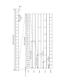
- FIG. 3 is a diagram showing an example of the configuration of a radio frame, subframe, and slot used in the wireless communication system 10. As shown in FIG. 3, one slot is composed of 14 symbols, and the larger (wider) the SCS is, the shorter the symbol period (and slot period) is.
- the SCS is not limited to the interval (frequency) shown in FIG. 3. For example, 480 kHz, 960 kHz, etc. may be used as the SCS.
- the number of symbols that make up one slot does not necessarily have to be 14 symbols (e.g., 28 or 56 symbols).
- the number of slots per subframe may differ depending on the SCS.
- time direction (t) shown in FIG. 3 may be called the time domain, symbol period, or symbol time, etc.
- the frequency direction may be called the frequency domain, resource block, subcarrier, bandwidth part (BWP), etc.
- DMRS Demodulation Reference Signal
- PDSCH Physical Downlink Shared Channel
- DMRS for an uplink data channel specifically, the PUSCH
- PUSCH Physical Downlink Shared Channel
- DMRS may be used for channel estimation at a device (e.g., UE 200) as part of coherent demodulation. DMRS may only be present in resource blocks (RBs) used for PDSCH transmission.
- RBs resource blocks
- the DMRS may have multiple mapping types. Specifically, the DMRS may have mapping type A and mapping type B. In mapping type A, the first DMRS may be placed in the second or third symbol of a slot. In mapping type A, the DMRS may be mapped relative to the slot boundary, regardless of where in the slot the actual data transmission starts. The reason for placing the first DMRS in the second or third symbol of a slot may be interpreted as being to place the first DMRS after the control resource sets (CORESET).
- CORESET control resource sets
- mapping type B the first DMRS may be placed in the first symbol of the data allocation. That is, the position of the DMRS may be given relative to where the data is placed, rather than relative to a slot boundary.
- DMRS may have multiple types. Specifically, DMRS may have Type 1 and Type 2. Type 1 and Type 2 differ in mapping in the frequency domain and the maximum number of orthogonal reference signals. Type 1 is a single-symbol DMRS that can output up to four orthogonal signals, and Type 2 is a double-symbol DMRS that can output up to eight orthogonal signals.
- the wireless communication system 10 may support coverage enhancement (CE) to expand the coverage of the cell (or physical channel) formed by the gNB 100.
- CE coverage enhancement
- a mechanism for increasing the success rate of reception of various physical channels, such as Msg3 repetition, may be provided.
- UE200 receives information related to the RACH procedure from gNB100 as a DL signal. Also, for example, UE200 receives information related to Msg3 repetition from gNB100 as a DL signal.
- the information related to Msg3 repetition may include information indicating, for example, the resources used for repeated transmission of Msg3, the number of repeated transmissions, the frequency hopping pattern, the specified offset used in frequency hopping, etc.
- UE200 transmits a special RACH occasion (RO) or a preamble for requesting Msg3 repetition in the RACH procedure to gNB100 as an UL signal. Also, for example, UE200 repeatedly transmits Msg3 to gNB100 as an UL signal based on information about Msg3 repetition received from gNB100 in response to the request for Msg3 repetition.
- RO RACH occasion
- the UL signal may include, for example, a UL data signal and control information.
- the UL signal may include information related to the processing capabilities of the UE 200 (e.g., UE capability).
- the UL signal may also include a reference signal.
- Channels used to transmit UL signals include, for example, data channels and control channels.
- the data channel may include a PUSCH
- the control channel may include a Physical Uplink Control Channel (PUCCH).
- PUCCH Physical Uplink Control Channel
- UE 200 transmits control information using a PUCCH and transmits UL data signals using a PUSCH.
- PUSCH is an example of an uplink shared channel
- PUCCH is an example of an uplink control channel.
- the shared channel may be referred to as a data channel.
- the reference signals included in the UL signal may include, for example, at least one of DMRS, Phase Tracking Reference Signal (PTRS), Channel State Information - Reference Signal (CSI-RS), Sounding Reference Signal (SRS), and Positioning Reference Signal (PRS) for location information.
- DMRS Phase Tracking Reference Signal
- CSI-RS Channel State Information - Reference Signal
- SRS Sounding Reference Signal
- PRS Positioning Reference Signal
- reference signals such as DMRS and PTRS are used to demodulate the UL data signal and are transmitted using PUSCH.
- RACH procedures are performed for initial access from RRC_Idle, RRC (Radio Resource Control) connection (re)establishment, beam failure recovery, handover, downlink data arrival, uplink data arrival, positioning, Timing Alignment (TA), etc.
- RACH procedures include the Contention Based Random Access (CBRA) procedure, which is a collision-type random access procedure, and the Contention Free Random Access (CFRA) procedure, which is a non-collision type random access procedure. Since the CBRA procedure is initiated by the UE 200 voluntarily, collisions may occur when multiple UEs 200 initiate the RACH procedure at the same time.
- CFRA allows the gNB 100 to instruct the connected UE 200 to execute the RACH procedure in a way that does not cause collisions between multiple UEs 200.
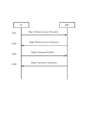
- FIG. 4 is a sequence diagram showing the CBRA procedure.
- UE 200 transmits a random access preamble (RA preamble) as a first message (Msg1) via a physical random access channel (PRACH).
- RA preamble a random access preamble
- Msg1 a first message
- PRACH physical random access channel
- UE 200 receives a response message (Random Access Response (RAR)) to Msg1 as a second message (Msg2) via the PDSCH.
- RAR Random Access Response
- Msg2 may monitor the PDCCH used for scheduling the PDSCH including Msg2.
- the CRC bits included in the PDCCH may be scrambled by a Random Access-Radio Network Temporary Identifier (RA-RNTI).
- Msg2 may include an uplink grant (RAR uplink grant) used for scheduling the PUSCH including Msg3.
- the RAR uplink grant may include a Temporary Cell-RNTI (TC-RNTI).
- the RAR uplink grant may include a TPC command indicating a correction value for the power control adjustment value used for the transmission power of the PUSCH including Msg3.
- UE200 transmits the PUSCH scheduled by the RAR uplink grant as a third message (Msg3).
- Msg3 may be called an RRC Connection Request.
- UE200 may repeatedly transmit the PUSCH of Msg3 to expand coverage.
- UE200 receives the collision resolution message as a fourth message (Msg4) via the PDCCH.
- Msg4 may monitor the PDCCH used for scheduling the PDSCH including Msg4.
- Msg4 may include a collision resolution ID (UE collision resolution ID). The collision resolution ID may be used to resolve collisions in which multiple UEs 200 transmit signals using the same radio resources. If the collision resolution ID included in Msg4 received by UE200 is the same value as the ID for identifying the UE 200, UE200 may determine that the collision resolution is successful and set the value of TC-RNTI in the C-RNTI field. When the value of TC-RNTI is set in the C-RNTI field, UE200 may consider that the RRC connection is completed. Msg4 may be called RRC Connection Setup.
- the UE 200 may transmit an Ack via the PUCCH (PUCCH resource) indicated by the PUCCH resource indication field included in the PDCCH that scheduled the Msg4 in order to notify the gNB 100 that the RRC connection has been completed.
- the UE 200 transmits a Capability to the gNB 100.
- the above-mentioned RACH procedure may be called a Type 1 RACH procedure, a 4-step RACH procedure, a Type 1 RACH, a 4-step RACH, etc.
- Capability is information indicating whether each function is supported or not, and may be called UE Capability, information regarding processing capabilities, capability information, etc.
- Msg3 may be called an uplink signal or a second uplink signal.
- Msg1 may be called a first uplink signal.
- Msg4 may be called a downlink signal or a second downlink signal.
- Msg2 may be called a first downlink signal.
- UE200 may control a RACH procedure consisting of a first step combining the above steps S101 and S103 and a second step combining the above steps S102 and S104.
- the RACH procedure may be called a Type 2 RACH procedure, a 2-step RACH procedure, Type 2 RACH, 2-step RACH, etc.
- a message combining the above Msg1 and Msg3 in the first step of the RACH procedure may be called MsgA
- a message combining the above Msg2 and Msg4 in the second step may be called MsgB.
- FIG. 5 is a sequence diagram showing the CFRA procedure.
- UE200 is requested to transmit an RA preamble (Msg1) from gNB100.
- gNB100 may allocate the RA preamble (Msg1) via dedicated signaling.
- the PDCCH for such dedicated signaling may be referred to as a PDCCH order.
- UE200 monitors the PDCCH (PDCCH order) to perform resource allocation for Msg1.
- step S202 UE200 transmits the above-mentioned Msg1.
- step S203 UE200 receives the above-mentioned Msg2.
- UE200 may transmit an Ack via PUCCH (PUCCH resources) to notify gNB100 that the RRC connection has been completed.
- PUCCH PUCCH resources
- UE200 transmits a parameter indicating a capability to gNB100 to notify whether it supports repeated transmission of Msg3.
- the channel used to transmit DL signals and the channel used to transmit UL signals are not limited to the above examples.
- the channel used to transmit DL signals and the channel used to transmit UL signals may include RACH and Physical Broadcast Channel (PBCH).
- the RACH may be used to transmit DCI including, for example, a Random Access Radio Network Temporary Identifier (RA-RNTI).
- RA-RNTI Random Access Radio Network Temporary Identifier
- Repetition type A and Repetition type B may be specified.
- Repetition type A may be interpreted as a form in which the PUSCH allocated within a slot is repeatedly transmitted. In other words, the PUSCH is 14 symbols or less and cannot be allocated across multiple slots (adjacent slots).
- PUSCH repetition Type A may also be called repetition Type A, PUSCH Type A repetition, Type A repetition, mapping Type A, data mapping Type A, Type A, etc.
- Repetition type B may be interpreted as repeated transmission of a PUSCH to which a PUSCH of 15 or more symbols may be assigned. In this embodiment, it may be permitted to assign such a PUSCH across multiple slots.
- PUSCH repetition Type B may also be referred to as repetition Type B, PUSCH Type B repetition, Type B repetition, mapping Type B, data mapping Type B, Type B, etc.
- multiple types of UEs 200 may be used that have different functions or performance, or that support different 3GPP releases.
- type may be replaced with other terms such as generation or release.
- a first type of terminal that supports a coverage expansion function and a second type of terminal that does not support a coverage expansion function, such as a Release-15 eMBB (enhanced Mobile Broadband) terminal may exist in the same cell.
- the first type of terminal and the second type of terminal may be referred to as enhanced UE and legacy UE, respectively.
- Expandable system 6G systems - systems that can scale - need to be designed to be future-proof for a variety of use cases without compromising performance.
- NR SSB bandwidth will be bottlenecked by bandwidth reduction for low-end IoT (eRedCap) devices.
- Example 2 Delayed introduction of some cell coverage extension features Since it is not practical to change cell deployments in a short time frame, the coverage extension features supported in future releases will only bring marginal benefits to cell coverage in the actual field.
- Release-17 stipulates the specifications for NTN (Non Terrestrial Network), which complements or extends terrestrial 5G systems with satellite networks so that 5G services can be provided in areas that cannot be covered by terrestrial mobile networks.
- NTN Non Terrestrial Network
- Release-18 NR NTN support for Msg4 HARQ-ACK repetition is being considered.
- UE200 monitors the PDCCH used for scheduling the PDSCH including Msg4, and decodes the PDCCH (e.g., DCI 1_0) and PDSCH. If UE200 successfully decodes Msg4, it transmits a HARQ-ACK for the data (PDSCH carrying Msg4) (hereinafter referred to as "Msg4 HARQ-ACK") on the PUCCH scheduled by the DCI. At this time, UE200 repeatedly transmits the HARQ-ACK according to the number of repetitions notified by the DCI (PUCCH repetition).
- PDCCH Physical Downlink Control Channel
- the UE 200 does not perform PUSCH repetition, but transmits signals such as the UE capability report on a single PUSCH scheduled by the DCI.
- UE200 does not perform PUCCH repetition, but transmits HARQ-ACK on a single PUCCH scheduled by DCI.
- Release-18 TEI Technical Enhancement or Important
- Release-19 propose repetition of the common PUSCH after the above Msg3 PUSCH transmission and the common PUCCH after the Msg4 HARQ-ACK transmission.
- UE200 it is optional for UE200 to report to gNB100 a parameter (e.g., pusch-RepetitionMsg3-r17) indicating the capability of whether or not it supports repeated transmission of PUSCH (Msg3) scheduled by RAR UL grant or DCI format 0_0.
- a parameter e.g., pusch-RepetitionMsg3-r17
- the UE 200 it is optional for the UE 200 to report to the gNB 100 a parameter (e.g., pusch-RepetitionTypeA-r16) indicating its capability for dynamic indication of the number of repetitions of PUSCH transmission.
- a parameter e.g., pusch-RepetitionTypeA-r16
- the terms described in this embodiment may be read as follows.
- the Msg2 PDCCH may be read as DCI format 1_0 with CRC scrambled by RA-RNTI.
- the Msg2 PDSCH may be read as a PDSCH including an RAR message.
- the Msg3 PUSCH may be read as an RAR UL grant or a PUSCH scheduled with DCI format 0_0 with CRC scrambled by TC-RNTI.
- the Msg4 PDSCH may be read as a PDSCH scheduled with DCI format 1_0 with CRC scrambled by TC-RNTI.
- the Msg4 PUCCH may be read as a PUCCH including HARQ-ACK/NACK info corresponding to a PDSCH scheduled with DCI format 1_0 with CRC scrambled by TC-RNTI.
- the common PUSCH may be read as a PUSCH scheduled with DCI format 0_0 with CRC scrambled by C-RNTI.
- the common PDSCH may be read as a PDSCH scheduled with DCI format 1_0 with CRC scrambled by C-RNTI.
- the common PUCCH may be read as a PUCCH including HARQ-ACK/NACK info corresponding to a PDSCH scheduled with DCI format 1_0 with CRC scrambled by C-RNTI.
- the common PDCCH with TC-RNTI may be read as DCI format 0_0 with CRC scrambled by TC-RNTI.
- the common PDCCH with MsgB-RNTI may be read as DCI format 0_0 with CRC scrambled by MsgB-RNTI.
- Communication PDCCH with C-RNTI may be read as DCI format 0_0/1_0 with CRC scrambled by C-RNTI.
- ⁇ Dedicated PUSCH may be read as PUSCH scheduled with DCI format 0_1 with CRC scrambled by C-RNTI/MCS-C-RNTI/CS-RNTI.
- ⁇ Dedicated PDSCH may be read as PDSCH scheduled with DCI format 1_1 with CRC scrambled by C-RNTI/MCS-C-RNTI/CS-RNTI.
- ⁇ Dedicated PUCCH may be read as PUCCH including HARQ-ACK/NACK info corresponding to PDSCH scheduled with DCI format 1_1 with CRC scrambled by C-RNTI/MCS-C-RNTI/CS-RNTI.
- - Dedicated PDCCH may be read as DCI format 0_1/1_1 with CRC scrambled by C-RNTI/MCS-C-RNTI.
- the leftmost notation is used for each of the above terms.
- the notations other than the leftmost notation for each term are those used in the RAN1 spec (TS38.211-TS38.214).
- the above DCI format is merely an example, and the present embodiment does not limit the DCI format.
- the above DCI format 0_0 may be DCI format 0_2/1_2, 0_3/1_3, or a new DCI format, etc.
- the above RNTI is merely an example, and the present embodiment does not limit the RNTI.
- the description C-RNTI/MCS-C-RNTI/CS-RNTI indicates that the RNTI may be any of C-RNTI, MCS-C-RNTI, and CS-RNTI.
- the inventors of the present disclosure have discovered that there are the following issues to be considered regarding UE200's support for coverage expansion functions and capabilities for coverage expansion functions.
- Capabilities related to repetition such as support for PUSCH repetition for each of the PRACH, Msg3, and Msg5 channels, are subdivided and complicated. That is, capabilities related to repetition are specified for each "(A) expression of the number of repetitions/number of slots", for each "(B) candidate channel", and for each "(C) transmission spanning multiple transmission units". If the UE 200 reports to the gNB 100 for each capability, the overhead of capability signaling will become large.
- UE 200 may be defined with the following capabilities related to coverage expansion functions: (A) expression of number of repetitions/number of slots, (B) candidate channels, and (C) transmission spanning multiple transmission units. Capabilities (A) to (C) are outlined below.
- a dynamic repetition instruction i.e., a dynamic instruction of the number of repetitions/number of slots by DCI, may be, for example, an instruction of the number of repetitions/number of slots by the TDRA or the PUCCH resource, where the number of repetitions/number of slots is linked to the value (row index) of the row in the TDRA table or the indicator field of the PUCCH resource.
- Each UE 200 is specified with a capability for dynamic repetition indication.
- UE 200 that supports dynamic repetition indication determines the number of repetitions/number of slots according to the Row Index of the indicated TDRA or the indicator field of the PUCCH resource.
- the gNB100 may instruct a UE200 that supports dynamic repetition instruction on the number of repetitions/number of slots by linking it to a TDRA or PUCCH resource.
- the gNB100 may dynamically instruct a UE200 that does not support dynamic repetition instruction on the number of repetitions/number of slots by other means without linking it to a TDRA or PUCCH resource, or may not dynamically instruct the number of repetitions/number of slots.
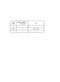
- Figure 7 shows an example of a TDRA table according to this proposal.
- the number of repetitions/number of slots is linked to the row index of the TDRA table.
- UE200 sets the number of repetitions/number of slots corresponding to the row index of the specified TDRA table. For example, in the example of Figure 7, when row index (#k) is specified, UE200 sets the number of repetitions/number of slots to "4".
- An example of an RRC setting-based instruction that is, a semi-static instruction of the number of repetitions/number of slots, is an instruction of the number of repetitions/number of slots by an RRC parameter.
- Each UE200 is specified with a capability for RRC setting-based instructions.
- UE200 that supports RRC setting-based instructions determines the number of repetitions/number of slots based on the RRC parameters transmitted from the gNB100.
- UE200 that supports RRC setting-based instructions may uniquely determine the number of repetitions/number of slots using the RRC parameters, or may determine the number of repetitions depending on the DL reception result (comparison result between the reception level and a threshold), etc. For example, when the reception level is lower than the threshold, UE200 sets the number of repetitions/number of slots instructed by the RRC parameters, and when the reception level is higher than the threshold, sets the number of repetitions/number of slots to "1" and does not perform repeated transmission.
- the gNB100 may instruct the number of repetitions/number of slots using RRC parameters to a UE200 that supports RRC setting-based instructions. On the other hand, the gNB100 does not instruct the number of repetitions/number of slots using RRC parameters to a UE200 that does not support RRC setting-based instructions.
- a capability for no instruction (processing for determining the number of repetitions/number of slots even without an instruction from the gNB 100) is defined for each UE 200.
- a UE 200 that supports no instruction determines the number of repetitions/number of slots, for example, according to a predetermined specification. In this case, the UE 200 may determine the number of repetitions/number of slots according to a DL reception result (a comparison result between a reception level and a threshold value), etc.
- the UE 200 when the reception level is lower than the threshold value, the UE 200 sets the number of repetitions/number of slots determined by the specification, and when the reception level is higher than the threshold value, the UE 200 sets the number of repetitions/number of slots to "1" and does not perform repeated transmission.
- the gNB100 does not need to instruct the number of repetitions/slots to a UE200 that supports no indication. On the other hand, the gNB100 instructs the number of repetitions/slots to a UE200 that does not support no indication.
- Candidate channels for repetition include PRACH, MsgA PRACH, Msg2 PDCCH, Msg2 PDSCH, Msg3 PUSCH, MsgA PUSCH, Msg4 PDSCH, MsgB PDCCH, MsgB PDSCH, Msg4 PUCCH, common PUSCH, common PDSCH, common PUCCH, common PDCCH with TC-RNTI, common PDCCH with C-RNTI, dedicated PUSCH, dedicated PDSCH, dedicated PUCCH, dedicated PDCCH, etc.
- Capabilities are set for each candidate channel.
- UE200 may bundle the capabilities of the channels for which repetition is to be performed, selected from the candidate channels, into one capability. For example, UE200 may report the capabilities for repetitive transmission for multiple candidate channels, such as PUSCH transmission (all PUSCH channels), PUCCH transmission (all PUCCH channels), PUSCH scheduled with DCI format 0_0, or PDSCH scheduled with DCI format 1_0, in one parameter.
- ⁇ (C) Transmission spanning multiple transmission units Capability is defined for each transmission format spanning multiple transmission units, such as repeated transmission, for each UE 200.
- Examples of the transmission unit include a slot, a subslot, and a symbol.
- UE200 may have a function of mapping the same data to each of the PUSCHs allocated to multiple slots and transmitting it repeatedly, or a function of transmitting one TB (Transport Block) using multiple slots.
- the transmission/reception symbols are mapped to the same symbol position in each slot to which the PUSCH resource is allocated.
- Examples of the above transmission form include PUSCH repetition type A, TB processing over multi-slot transmission, repetition for PUCCH over multiple slots, etc.
- UE200 may have a function of mapping the same data to each of the PUSCHs assigned to multiple subslots/symbols and transmitting it repeatedly, or a function of transmitting one TB using multiple subslots/symbol slots.
- Examples of the above transmission form include PUSCH repetition type B, repetition for PUCCH over multiple PUCCH subslots, etc.
- UE200 may bundle each of the capabilities (A) to (C) and generate one parameter (hereinafter referred to as "bundling parameter") indicating these capabilities. That is, UE200 may generate one bundling parameter indicating at least one capability of "(C) transmission spanning multiple transmission units" for at least one "(B) candidate channel” based on at least one "(A) expression of number of repetitions/number of slots” and report this bundling parameter to gNB100 (network).
- bundling parameter indicating at least one capability of "(C) transmission spanning multiple transmission units" for at least one "(B) candidate channel” based on at least one "(A) expression of number of repetitions/number of slots”
- UE200 may report the bundling parameters to gNB100 after the initial connection is completed.
- UE200 may also report capabilities related to channels at the time of initial connection, such as PRACH, to gNB100 after the initial connection is completed.
- gNB100 can refer to capabilities related to channels at the time of initial connection during handover.
- UE200 may report the above bundling parameters to gNB100, including the capabilities shown in each of the following options.
- PUSCH repetition schemes (schemes for repeatedly transmitting PUSCHs associated with different spatial relations, UL TCI-states, joint TCI-states, and power control parameter sets by TDD) may be defined for each UE 200.
- the above schemes include multi-TRP PUSCH repetition based on codebook with PUSCH repetition type A/B, multi-TRP PUSCH repetition for non-codebook based PUSCH repetition type A/B, etc.
- UE200 when UE200 includes the above capabilities in the bundling parameters, it may further include capabilities for supporting sequential mapping and/or cyclic mapping in the bundling parameters.
- Option 2 Capabilities for one or more Multi-TRP PUCCH repetition schemes (schemes for repeatedly transmitting PUCCHs associated with different spatial relations, UL TCI-states, joint TCI-states, and power control parameter sets in TDD) may be defined for each UE 200.
- the above schemes include PUCCH repetition scheme 1, PUCCH repetition scheme 3, and the like.
- UE200 when UE200 includes the above capabilities in the bundling parameters, it may further include capabilities for supporting sequential mapping and/or cyclic mapping in the bundling parameters.
- Capabilities for one or more frequency hopping schemes may be defined for each UE 200.
- the above schemes include inter-subslot frequency hopping for PUCCH, inter-slot frequency hopping for PUCCH, enhanced inter-slot frequency hopping for DMRS bundling for PUCCH, inter-slot frequency hopping for PUSCH, intra-slot frequency hopping for PUSCH, enhanced inter-slot frequency hopping for DMRS bundling for PUSCH, etc.
- Each UE 200 may be defined with a capability for DMRS bundling for each candidate channel shown in the section “(B) Candidate Channels” of Proposal 1 above.
- those to be included in the bundling parameters may be fixedly determined by the specifications, or may be dynamically determined based on the type of UE 200, etc.
- UE 200 may always supports each of the capabilities listed in Proposal 1 above, or functions (coverage extension functions) corresponding to each of the capabilities listed in Proposal 1 and its variations.
- UE200 may report to gNM100 a parameter indicating a capability indicating that it supports the mandatory function (mandatory with signaling), or it may not report the parameter (mandatory without signaling).
- ⁇ Proposal 2-2> If certain conditions are met, it may be mandatory (conditional mandatory) for UE200 to support each capability listed in Proposal 1 above, or a function (coverage extension function) corresponding to each capability listed in Proposal 1 and its variations.
- UE200 may report to gNM100 a parameter indicating a capability indicating that it supports the conditional mandatory function (conditional mandatory with signaling), or it may not report the parameter (conditional mandatory without signaling).
- the "particular conditions" may be, for example: - UE200 supports a function corresponding to a specific capability. - UE200 supports communication at a specific frequency (e.g., a specific band, a specific FR). - UE200 is a specific UE type (e.g., RedCap UE). - UE200 has made an initial connection on a specific PRACH. - UE200 supports NR Rel-XX or later releases.
- the gNB100 can communicate with all enhanced UE200 present within the extended coverage range.
- legacy UE that does not support the coverage expansion function cannot communicate in 6G systems, and can only communicate in legacy systems.
- the coverage extension function (particularly, the function related to repetition transmission) is subdivided for each channel.
- the UE 200 transmits, using one channel, information indicating that the UE 200 supports or requests the function related to multiple repetitions described in Proposal 1, i.e., at least one function of "(C) transmission across multiple transmission units" for at least one "(B) candidate channel” based on at least one "(A) expression of the number of repetitions/number of slots".
- support report/request information for reporting or requesting that a feature related to repetition is supported
- the UE 200 transmits a PRACH including information of the support report/request in a specific PRACH resource (PRACH preamble and/or RACH occasion).
- it can be set as one of the feature combinations for the above support report/request, and UE200 can report/request support by transmitting a PRACH resource associated with that feature combination.
- the UE 200 transmits the support report/request information by the Msg3/MsgA PUSCH.
- support report/request information may be included in higher layer signaling transmitted via Msg3 PUSCH.
- UE200 may report/request support of the capabilities listed in the variations of Proposal 1 to gNB100 based on each option of Proposal 3-1 above.
- Proposal 1 the capabilities listed in the variations of Proposal 1 may be reported/requested as supported using the same signals (channels) as those listed in each option of Proposal 3-1 above.
- support reports/requests for repetition and DMRS bundling may be set as one of the Feature Combinations.
- UE200 may determine whether or not to make a support report/request as described in Proposal 3-1/3-2 above, according to each of the following options.
- the UE 200 may determine whether to make a support report/request based on whether the reception level of the DL/PL/RSRP (Reference Signal Received Power) or the like is higher or lower than a threshold. For example, the UE 200 makes a support report/request when the RSRP is lower than the threshold, and does not make a support report/request when the RSRP is higher than the threshold.
- the threshold may be set to a value determined in advance by a specification, or may be determined by the UE 200 based on information (e.g., SIB1) received from the gNB 100 (network).
- thresholds may be set/determined as follows:
- the threshold may be a value associated with a set of multiple candidate channels.
- the UE 200 may set a threshold for making a request for the Msg3 PUSCH and the Msg4 PUCCH.
- the threshold may be a minimum or maximum value of thresholds associated with each of the candidate channels among the multiple candidate channels. For example, UE 200 may set the minimum value of the threshold for determining whether to request Msg3 PUSCH and the threshold for determining whether to request Msg4 PUCCH as the threshold for requesting Msg3 PUSCH and Msg4 PUCCH.
- thresholds may be set/determined as shown in the following suboptions.
- the threshold may be a value associated with a set of multiple functions.
- the UE 200 may set a threshold for requesting both the function of “(C) Transmission across multiple transmission units” and the function listed in the variation of Proposal 1.
- the threshold may be a minimum or maximum value of the threshold associated with each function.
- the UE 200 may set the minimum value of the threshold for whether to request the function of "(C) transmission across multiple transmission units" and the threshold for whether to request the function listed in the variation of proposal 1 as the threshold for requesting both the function of "(C) transmission across multiple transmission units" and the function listed in the variation of proposal 1.
- the UE 200 may determine whether to make a support report/request based on whether each function is supported. For example, if the UE 200 supports a target function, the UE 200 always makes a support report/request.
- UE 200 may determine whether to make a support report/request based on whether the UE 200 has been configured/instructed by the network to make a support report/request.
- UE200 may set/determine a threshold for the reception level of RSRP or the like or a threshold for power headroom depending on the power class supported by UE200, and may determine whether or not to make a support report/request based on whether the RSRP/power headroom is higher or lower than the threshold.
- UE200 may set/determine a threshold for the reception level of RSR P or the like or a threshold for the power headroom according to the PCmax value at the timing of determining whether to make a support report/request, and may determine whether to make a support report/request based on whether the RSRP/power headroom is higher or lower than the threshold.
- the PCmax value is used to determine whether high-power UL transmission is possible.
- the UE 200 may determine whether to report/request support based on whether the power headroom for the target UL channel is above or below a threshold, where the threshold may be determined in a manner similar to option 1 above.
- a channel for reporting/requesting support may be set according to the type of UE 200.
- UE 200 when UE 200 has already reported its type to gNB 100, it may report/request support on a channel corresponding to the type, and when UE 200 has not yet reported its type to gNB 100, it may report/request support on a specific channel.
- the gNB100 and UE200 include functions for performing the above-mentioned embodiments. However, the gNB100 and UE200 may each have only a part of the functions in the embodiments.
- Fig. 8 is a diagram showing an example of the functional configuration of the gNB 100.
- the gNB 100 has a receiving unit 101, a transmitting unit 102, and a control unit 103.
- the functional configuration shown in Fig. 8 is merely an example. As long as the operation related to the embodiment of the present invention can be performed, the names of the functional divisions and functional units may be any.
- the receiver 101 has a function of receiving various signals transmitted from the UE 200 and acquiring, for example, information of a higher layer from the received signals.
- the transmitter 102 has a function of generating a signal to be transmitted to the UE 200 and transmitting the signal via a wired or wireless connection.
- the control unit 103 stores preset setting information and various setting information to be transmitted to the UE 200 in a storage device, and reads them out from the storage device as necessary.
- the control unit 103 also executes processing related to communication with the UE 200.
- the functional unit related to signal transmission in the control unit 103 may be included in the transmitting unit 102, and the functional unit related to signal reception in the control unit 103 may be included in the receiving unit 101.
- Fig. 9 is a diagram showing an example of a functional configuration of the UE 200.
- the UE 200 has a transmitting unit 201, a receiving unit 202, and a control unit 203.
- the functional configuration shown in Fig. 9 is merely an example. As long as the operation according to the embodiment of the present invention can be performed, the names of the functional divisions and the functional units may be any names.
- the transmitting unit 201 creates a transmission signal from the transmission data and transmits the transmission signal wirelessly.
- the receiving unit 202 receives various signals wirelessly and acquires higher layer signals from the received physical layer signals.
- the receiving unit 202 also has a function of receiving NR-PSS, NR-SSS, NR-PBCH, DL/UL control signals, reference signals, etc. transmitted from the gNB100.
- the control unit 203 stores various setting information received from the gNB100 by the receiving unit 202 in a storage device, and reads it from the storage device as necessary.
- the control unit 203 also executes processing related to communication with the gNB100.
- the functional unit related to signal transmission in the control unit 203 may be included in the transmitting unit 201, and the functional unit related to signal reception in the control unit 203 may be included in the receiving unit 202.
- each functional block may be realized using one device that is physically or logically coupled, or may be realized using two or more devices that are physically or logically separated and directly or indirectly connected (for example, using wires, wirelessly, etc.).
- the functional blocks may be realized by combining the one device or the multiple devices with software.
- Functions include, but are not limited to, judgement, determination, judgment, calculation, computation, processing, derivation, investigation, search, confirmation, reception, transmission, output, access, resolution, selection, election, establishment, comparison, assumption, expectation, regard, broadcasting, notifying, communicating, forwarding, configuring, reconfiguring, allocating, mapping, and assignment.
- a functional block (component) that performs the transmission function is called a transmitting unit or transmitter.
- a base station, a terminal, etc. in one embodiment of the present disclosure may function as a computer that performs processing of the wireless communication method of the present disclosure.
- FIG. 10 is a diagram showing an example of the hardware configuration of a base station and a terminal in one embodiment of the present disclosure.
- the above-mentioned base station 100 and terminal 200 may be physically configured as a computer device including a processor 1001, a memory 1002, a storage 1003, a communication device 1004, an input device 1005, an output device 1006, a bus 1007, etc.
- the term "apparatus” can be interpreted as a circuit, device, unit, etc.
- the hardware configuration of the base station 100 and the terminal 200 may be configured to include one or more of the devices shown in the figure, or may be configured to exclude some of the devices.
- the functions of the base station 100 and the terminal 200 are realized by loading specific software (programs) onto hardware such as the processor 1001 and memory 1002, causing the processor 1001 to perform calculations, control communications by the communication device 1004, and control at least one of the reading and writing of data in the memory 1002 and the storage 1003.
- the processor 1001 for example, operates an operating system to control the entire computer.
- the processor 1001 may be configured as a central processing unit (CPU) including an interface with peripheral devices, a control unit, an arithmetic unit, registers, etc.
- CPU central processing unit
- control unit 103, control unit 203, and control unit 303, etc. may be realized by the processor 1001.
- the processor 1001 also reads out programs (program codes), software modules, data, etc. from at least one of the storage 1003 and the communication device 1004 into the memory 1002, and executes various processes according to these.
- the programs used are those that cause a computer to execute at least some of the operations described in the above-mentioned embodiments.
- the base station 100 and the terminal 200 may be realized by a control program stored in the memory 1002 and running on the processor 1001, and similarly may be realized for other functional blocks.
- the above-mentioned various processes have been described as being executed by one processor 1001, they may be executed simultaneously or sequentially by two or more processors 1001.
- the processor 1001 may be implemented by one or more chips.
- the programs may be transmitted from a network via a telecommunications line.
- Memory 1002 is a computer-readable recording medium and may be composed of, for example, at least one of a ROM (Read Only Memory), an EPROM (Erasable Programmable ROM), an EEPROM (Electrically Erasable Programmable ROM), a RAM (Random Access Memory), etc.
- Memory 1002 may also be called a register, a cache, a main memory, etc.
- Memory 1002 can store executable programs (program codes), software modules, etc. for implementing a wireless communication method relating to one embodiment of the present disclosure.
- Storage 1003 is a computer-readable recording medium, and may be, for example, at least one of an optical disk such as a CD-ROM (Compact Disc ROM), a hard disk drive, a flexible disk, a magneto-optical disk (e.g., a compact disk, a digital versatile disk, a Blu-ray (registered trademark) disk), a smart card, a flash memory (e.g., a card, a stick, a key drive), a floppy (registered trademark) disk, a magnetic strip, etc.
- Storage 1003 may also be referred to as an auxiliary storage device.
- the above-mentioned storage medium may be, for example, a database, a server, or other suitable medium including at least one of memory 1002 and storage 1003.
- the communication device 1004 is hardware (transmitting/receiving device) for communicating between computers via at least one of a wired network and a wireless network, and is also referred to as, for example, a network device, a network controller, a network card, a communication module, etc.
- the communication device 1004 may be configured to include a high-frequency switch, a duplexer, a filter, a frequency synthesizer, etc., to realize at least one of, for example, Frequency Division Duplex (FDD) and Time Division Duplex (TDD).
- FDD Frequency Division Duplex
- TDD Time Division Duplex
- the above-mentioned transmitting unit 101, transmitting unit 202, transmitting unit 302, receiving unit 102, receiving unit 201, receiving unit 301, etc. may be realized by the communication device 1004.
- the communication device 1004 may be implemented with the transmitting unit and the receiving unit being physically or logically separated.
- the input device 1005 is an input device (e.g., a keyboard, a mouse, a microphone, a switch, a button, a sensor, etc.) that accepts input from the outside.
- the output device 1006 is an output device (e.g., a display, a speaker, an LED lamp, etc.) that performs output to the outside. Note that the input device 1005 and the output device 1006 may be integrated into one structure (e.g., a touch panel).
- each device such as the processor 1001 and memory 1002 is connected by a bus 1007 for communicating information.
- the bus 1007 may be configured using a single bus, or may be configured using different buses between each device.
- the base station 100 and the terminal 200 may be configured to include hardware such as a microprocessor, a digital signal processor (DSP), an application specific integrated circuit (ASIC), a programmable logic device (PLD), or a field programmable gate array (FPGA), and some or all of the functional blocks may be realized by the hardware.
- the processor 1001 may be implemented using at least one of these pieces of hardware.
- the operations of multiple functional units may be physically performed by one part, or the operations of one functional unit may be physically performed by multiple parts.
- the order of the processing procedures described in the embodiments may be changed as long as there is no contradiction.
- the base station 100 and the terminal 200 have been described using functional block diagrams, but such devices may be realized by hardware, software, or a combination thereof.
- the software operated by the processor of the base station 100 in accordance with an embodiment of the present disclosure, and the software operated by the processor of the terminal 200 in accordance with an embodiment of the present disclosure may each be stored in random access memory (RAM), flash memory, read-only memory (ROM), EPROM, EEPROM, register, hard disk (HDD), removable disk, CD-ROM, database, server, or any other suitable storage medium.
- the notification of information is not limited to the embodiment described in the present disclosure, and may be performed using other methods.
- the notification of information may be performed by physical layer signaling (e.g., Downlink Control Information (DCI), Uplink Control Information (UCI)), higher layer signaling (e.g., Radio Resource Control (RRC) signaling, Medium Access Control (MAC) signaling, broadcast information (Master Information Block (MIB), System Information Block (SIB)), other signals, or combinations thereof.
- the RRC signaling may be called an RRC message, and may be, for example, an RRC Connection Setup message, an RRC Connection Reconfiguration message, or the like.
- LTE Long Term Evolution
- LTE-A LTE-Advanced
- SUPER 3G IMT-Advanced
- 4th generation mobile communication system 4th generation mobile communication system
- 5th generation mobile communication system 5G
- 6th generation mobile communication system 6th generation mobile communication system
- xth generation mobile communication system xG (x is, for example, an integer or a decimal)
- Future Radio Access FAA
- new Radio NR
- New radio access NX
- Future generation radio access Future generation radio access
- W-CDMA registered trademark
- GSM registered trademark
- UMB Ultra Mobile Broadband
- IEEE 802.11 Wi-Fi (registered trademark)
- IEEE 802.16 WiMAX (registered trademark)
- IEEE 802.17 WiMAX (registered trademark)
- IEEE 802.19 WiMAX (registered trademark)
- IEEE 802.20 WiMAX (registered trademark)
- IEEE 802.21 WiMAX (registered trademark)
- a specific operation performed by a base station may be performed by its upper node in some cases.
- various operations performed for communication with a terminal may be performed by at least one of the base station and other network nodes other than the base station (e.g., MME or S-GW, etc., but are not limited to these).
- MME Mobility Management Entity
- S-GW Serving Mobility Management Entity
- the above example illustrates a case where there is one other network node other than the base station, it may be a combination of multiple other network nodes (e.g., MME and S-GW).
- Information, etc. may be output from a higher layer (or a lower layer) to a lower layer (or a higher layer).
- Information may be input and output via multiple network nodes.
- the input and output information may be stored in a specific location (e.g., memory) or may be managed using a management table.
- the input and output information may be overwritten, updated, or added.
- the output information may be deleted.
- the input information may be transmitted to another device.
- the determination may be based on a value represented by one bit (0 or 1), a Boolean value (true or false), or a numerical comparison (e.g., comparison with a predetermined value).
- notification of predetermined information is not limited to being done explicitly, but may be done implicitly (e.g., not notifying the predetermined information).
- Software shall be construed broadly to mean instructions, instruction sets, code, code segments, program code, programs, subprograms, software modules, applications, software applications, software packages, routines, subroutines, objects, executable files, threads of execution, procedures, functions, etc., whether referred to as software, firmware, middleware, microcode, hardware description language, or otherwise.
- software, instructions, information, etc. may be transmitted and received via a transmission medium.
- a transmission medium For example, if the software is transmitted from a website, server, or other remote source using at least one of wired technologies (such as coaxial cable, fiber optic cable, twisted pair, Digital Subscriber Line (DSL)), and/or wireless technologies (such as infrared, microwave, etc.), then at least one of these wired and wireless technologies is included within the definition of a transmission medium.
- wired technologies such as coaxial cable, fiber optic cable, twisted pair, Digital Subscriber Line (DSL)
- wireless technologies such as infrared, microwave, etc.
- the information, signals, etc. described in this disclosure may be represented using any of a variety of different technologies.
- the data, instructions, commands, information, signals, bits, symbols, chips, etc. that may be referred to throughout the above description may be represented by voltages, currents, electromagnetic waves, magnetic fields or magnetic particles, optical fields or photons, or any combination thereof.
- At least one of the channel and the symbol may be a signal (signaling).
- the signal may be a message.
- a component carrier (CC) may be called a carrier frequency, a cell, a frequency carrier, etc.
- the information, parameters, etc. described in the present disclosure may be represented using absolute values, may be represented using relative values from a predetermined value, or may be represented using other corresponding information.
- a radio resource may be indicated by an index.
- the names used for the above-mentioned parameters are not limiting in any respect. Furthermore, the formulas etc. using these parameters may differ from those explicitly disclosed in this disclosure.
- the various channels (e.g., PUCCH, PDCCH, etc.) and information elements may be identified by any suitable names, and therefore the various names assigned to these various channels and information elements are not limiting in any respect.
- Base station BS
- radio base station fixed station
- NodeB NodeB
- eNodeB eNodeB
- gNodeB gNodeB
- a base station may also be referred to by terms such as a macro cell, a small cell, a femto cell, a pico cell, etc.
- a base station can accommodate one or more (e.g., three) cells.
- a base station accommodates multiple cells, the entire coverage area of the base station can be divided into multiple smaller areas, and each smaller area can also provide communication services by a base station subsystem (e.g., a small indoor base station (RRH: Remote Radio Head).
- RRH Remote Radio Head
- the term "cell” or “sector” refers to a part or the entire coverage area of at least one of the base station and base station subsystems that provide communication services in this coverage.
- a base station transmitting information to a terminal may be interpreted as the base station instructing the terminal to control or operate based on the information.
- MS Mobile Station
- UE User Equipment
- a mobile station may also be referred to by those skilled in the art as a subscriber station, mobile unit, subscriber unit, wireless unit, remote unit, mobile device, wireless device, wireless communication device, remote device, mobile subscriber station, access terminal, mobile terminal, wireless terminal, remote terminal, handset, user agent, mobile client, client, or some other suitable terminology.
- At least one of the base station and the mobile station may be called a transmitting device, a receiving device, a communication device, etc.
- At least one of the base station and the mobile station may be a device mounted on a moving object, the moving object itself, etc.
- the moving object refers to an object that can move, and the moving speed is arbitrary. It also naturally includes the case where the moving object is stopped.
- the moving object includes, but is not limited to, for example, a vehicle, a transport vehicle, an automobile, a motorcycle, a bicycle, a connected car, an excavator, a bulldozer, a wheel loader, a dump truck, a forklift, a train, a bus, a handcar, a rickshaw, a ship and other watercraft, an airplane, a rocket, an artificial satellite, a drone (registered trademark), a multicopter, a quadcopter, a balloon, and objects mounted thereon.
- the moving object may also be a moving object that runs autonomously based on an operation command.
- At least one of the base station and the mobile station may be a device that does not necessarily move during communication operations.
- at least one of the base station and the mobile station may be an IoT (Internet of Things) device such as a sensor.
- IoT Internet of Things
- the base station in the present disclosure may be read as a terminal.
- the embodiment of the present disclosure may be applied to a configuration in which communication between a base station and a terminal is replaced with communication between multiple terminals (which may be called, for example, D2D (Device-to-Device) or V2X (Vehicle-to-Everything)).
- the terminal 200 may be configured to have the functions of the base station 100 described above.
- terms such as "uplink” and "downlink” may be read as terms corresponding to communication between terminals (for example, "side”).
- the uplink channel, downlink channel, etc. may be read as a side channel.
- the terminal in this disclosure may be interpreted as a base station.
- the base station 100 may be configured to have the functions of the terminal 200 described above.
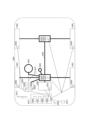
- FIG. 11 shows an example configuration of a vehicle 2001.
- the vehicle 2001 includes a drive unit 2002, a steering unit 2003, an accelerator pedal 2004, a brake pedal 2005, a shift lever 2006, front wheels 2007, rear wheels 2008, an axle 2009, an electronic control unit 2010, various sensors 2021-2029, an information service unit 2012, and a communication module 2013.
- a communication device mounted on the vehicle 2001 and may be applied to the communication module 2013, for example.
- the drive unit 2002 is composed of, for example, an engine, a motor, or a hybrid of an engine and a motor.
- the steering unit 2003 includes at least a steering wheel (also called a handlebar), and is configured to steer at least one of the front wheels and the rear wheels based on the operation of the steering wheel operated by the user.
- the electronic control unit 2010 is composed of a microprocessor 2031, memory (ROM, RAM) 2032, and a communication port (IO port) 2033. Signals are input to the electronic control unit 2010 from various sensors 2021 to 2029 provided in the vehicle 2001.
- the electronic control unit 2010 may also be called an ECU (Electronic Control Unit).
- Signals from the various sensors 2021-2029 include a current signal from a current sensor 2021 that senses the motor current, a front and rear wheel rotation speed signal obtained by a rotation speed sensor 2022, a front and rear wheel air pressure signal obtained by an air pressure sensor 2023, a vehicle speed signal obtained by a vehicle speed sensor 2024, an acceleration signal obtained by an acceleration sensor 2025, an accelerator pedal depression amount signal obtained by an accelerator pedal sensor 2029, a brake pedal depression amount signal obtained by a brake pedal sensor 2026, a shift lever operation signal obtained by a shift lever sensor 2027, and a detection signal for detecting obstacles, vehicles, pedestrians, etc. obtained by an object detection sensor 2028.
- the information service unit 2012 is composed of various devices, such as a car navigation system, an audio system, speakers, a television, and a radio, for providing (outputting) various information such as driving information, traffic information, and entertainment information, and one or more ECUs for controlling these devices.
- the information service unit 2012 uses information acquired from external devices via the communication module 2013, etc., to provide various multimedia information and multimedia services to the occupants of the vehicle 2001.
- the information service unit 2012 may include input devices (e.g., a keyboard, a mouse, a microphone, a switch, a button, a sensor, a touch panel, etc.) that accept input from the outside, and may also include output devices (e.g., a display, a speaker, an LED lamp, a touch panel, etc.) that perform output to the outside.
- input devices e.g., a keyboard, a mouse, a microphone, a switch, a button, a sensor, a touch panel, etc.
- output devices e.g., a display, a speaker, an LED lamp, a touch panel, etc.
- the driving assistance system unit 2030 is composed of various devices that provide functions for preventing accidents and reducing the driving burden on the driver, such as a millimeter wave radar, LiDAR (Light Detection and Ranging), a camera, a positioning locator (e.g., GNSS, etc.), map information (e.g., high definition (HD) maps, autonomous vehicle (AV) maps, etc.), a gyro system (e.g., IMU (Inertial Measurement Unit), INS (Inertial Navigation System), etc.), AI (Artificial Intelligence) chip, and AI processor, as well as one or more ECUs that control these devices.
- the driving assistance system unit 2030 transmits and receives various information via the communication module 2013 to realize driving assistance functions or autonomous driving functions.
- the communication module 2013 can communicate with the microprocessor 2031 and components of the vehicle 2001 via the communication port.
- the communication module 2013 transmits and receives data via the communication port 2033 between the drive unit 2002, steering unit 2003, accelerator pedal 2004, brake pedal 2005, shift lever 2006, front wheels 2007, rear wheels 2008, axle 2009, microprocessor 2031 and memory (ROM, RAM) 2032 in the electronic control unit 2010, and sensors 2021 to 2029 that are provided on the vehicle 2001.
- the communication module 2013 is a communication device that can be controlled by the microprocessor 2031 of the electronic control unit 2010 and can communicate with an external device. For example, it transmits and receives various information to and from the external device via wireless communication.
- the communication module 2013 may be located either inside or outside the electronic control unit 2010.
- the external device may be, for example, a base station, a mobile station, etc.
- the communication module 2013 may transmit at least one of the signals from the various sensors 2021-2029 described above input to the electronic control unit 2010, information obtained based on the signals, and information based on input from the outside (user) obtained via the information service unit 2012 to an external device via wireless communication.
- the electronic control unit 2010, the various sensors 2021-2029, the information service unit 2012, etc. may be referred to as input units that accept input.
- the PUSCH transmitted by the communication module 2013 may include information based on the above input.
- the communication module 2013 receives various information (traffic information, signal information, vehicle distance information, etc.) transmitted from an external device, and displays it on the information service unit 2012 provided in the vehicle 2001.
- the information service unit 2012 may be called an output unit that outputs information (for example, outputs information to a device such as a display or speaker based on the PDSCH (or data/information decoded from the PDSCH) received by the communication module 2013).
- the communication module 2013 also stores various information received from an external device in a memory 2032 that can be used by the microprocessor 2031.
- the microprocessor 2031 may control the drive unit 2002, steering unit 2003, accelerator pedal 2004, brake pedal 2005, shift lever 2006, front wheels 2007, rear wheels 2008, axles 2009, sensors 2021 to 2029, etc. provided in the vehicle 2001.
- determining and “determining” as used in this disclosure may encompass a wide variety of actions. “Determining” and “determining” may include, for example, judging, calculating, computing, processing, deriving, investigating, looking up, searching, inquiring (e.g., searching in a table, database, or other data structure), ascertaining, and the like. “Determining” and “determining” may also include receiving (e.g., receiving information), transmitting (e.g., sending information), input, output, accessing (e.g., accessing data in a memory), and the like. “Determining” and “determining” may also include resolving, selecting, choosing, establishing, comparing, and the like. In other words, “judgment” and “decision” can include regarding some action as having been “judged” or “decided.” Also, “judgment (decision)” may be interpreted as “assuming,””expecting,””considering,” etc.
- connection refers to any direct or indirect connection or coupling between two or more elements, and may include the presence of one or more intermediate elements between two elements that are “connected” or “coupled” to each other.
- the coupling or connection between elements may be physical, logical, or a combination thereof.
- “connected” may be read as "access”.
- two elements may be considered to be “connected” or “coupled” to each other using at least one of one or more wires, cables, and printed electrical connections, as well as electromagnetic energy having wavelengths in the radio frequency range, microwave range, and optical (both visible and invisible) range, as some non-limiting and non-exhaustive examples.
- the reference signal may be abbreviated as RS (Reference Signal) or may be called a pilot depending on the applicable standard.
- a radio frame may be composed of one or more frames in the time domain. Each of the one or more frames in the time domain may be called a subframe. A subframe may further be composed of one or more slots in the time domain. A subframe may have a fixed time length (e.g., 1 ms) that is independent of numerology.
- Numerology may be a communication parameter that applies to at least one of the transmission and reception of a signal or channel. Numerology may indicate, for example, at least one of the following: Subcarrier Spacing (SCS), bandwidth, symbol length, cyclic prefix length, Transmission Time Interval (TTI), number of symbols per TTI, radio frame structure, a particular filtering process performed by the transceiver in the frequency domain, a particular windowing process performed by the transceiver in the time domain, etc.
- SCS Subcarrier Spacing
- TTI Transmission Time Interval
- radio frame structure a particular filtering process performed by the transceiver in the frequency domain, a particular windowing process performed by the transceiver in the time domain, etc.
- a slot may consist of one or more symbols in the time domain (such as Orthogonal Frequency Division Multiplexing (OFDM) symbols, Single Carrier Frequency Division Multiple Access (SC-FDMA) symbols, etc.).
- OFDM Orthogonal Frequency Division Multiplexing
- SC-FDMA Single Carrier Frequency Division Multiple Access
- a slot may be a time unit based on numerology.
- a slot may include multiple minislots. Each minislot may consist of one or multiple symbols in the time domain. A minislot may also be called a subslot. A minislot may consist of fewer symbols than a slot.
- a PDSCH (or PUSCH) transmitted in a time unit larger than a minislot may be called PDSCH (or PUSCH) mapping type A.
- a PDSCH (or PUSCH) transmitted using a minislot may be called PDSCH (or PUSCH) mapping type B.
- Radio frame, subframe, slot, minislot, and symbol all represent time units for transmitting signals. Radio frame, subframe, slot, minislot, and symbol may each be referred to by a different name that corresponds to the radio frame, subframe, slot, minislot, and symbol.
- one subframe may be called a Transmission Time Interval (TTI)
- TTI Transmission Time Interval
- multiple consecutive subframes may be called a TTI
- one slot or one minislot may be called a TTI.
- at least one of the subframe and the TTI may be a subframe (1 ms) in existing LTE, a period shorter than 1 ms (e.g., 1-13 symbols), or a period longer than 1 ms.
- the unit representing the TTI may be called a slot, minislot, etc., instead of a subframe.
- TTI refers to, for example, the smallest time unit for scheduling in wireless communication.
- a base station schedules each user terminal by allocating radio resources (such as frequency bandwidth and transmission power that can be used by each user terminal) in TTI units.
- radio resources such as frequency bandwidth and transmission power that can be used by each user terminal
- the TTI may be a transmission time unit for a channel-coded data packet (transport block), a code block, a code word, etc., or may be a processing unit for scheduling, link adaptation, etc.
- the time interval e.g., the number of symbols
- the time interval in which a transport block, a code block, a code word, etc. is actually mapped may be shorter than the TTI.
- one or more TTIs may be the minimum time unit of scheduling.
- the number of slots (minislots) that constitute the minimum time unit of scheduling may be controlled.
- a TTI having a time length of 1 ms may be referred to as a normal TTI (TTI in LTE Rel. 8-12), normal TTI, long TTI, normal subframe, normal subframe, long subframe, slot, etc.
- TTI shorter than a normal TTI may be referred to as a shortened TTI, short TTI, partial or fractional TTI, shortened subframe, short subframe, minislot, subslot, slot, etc.
- a long TTI (e.g., a normal TTI, a subframe, etc.) may be interpreted as a TTI having a time length of more than 1 ms
- a short TTI e.g., a shortened TTI, etc.
- TTI length shorter than the TTI length of a long TTI and equal to or greater than 1 ms.
- a resource block is a resource allocation unit in the time domain and frequency domain, and may include one or more consecutive subcarriers in the frequency domain.
- the number of subcarriers included in an RB may be the same regardless of the numerology, and may be, for example, 12.
- the number of subcarriers included in an RB may be determined based on the numerology.
- the time domain of an RB may include one or more symbols and may be one slot, one minislot, one subframe, or one TTI in length.
- One TTI, one subframe, etc. may each be composed of one or more resource blocks.
- one or more RBs may also be referred to as a physical resource block (PRB), a sub-carrier group (SCG), a resource element group (REG), a PRB pair, an RB pair, etc.
- PRB physical resource block
- SCG sub-carrier group
- REG resource element group
- PRB pair an RB pair, etc.
- a resource block may be composed of one or more resource elements (REs).
- REs resource elements
- one RE may be a radio resource area of one subcarrier and one symbol.
- a Bandwidth Part which may also be referred to as a partial bandwidth, may represent a subset of contiguous common resource blocks (RBs) for a given numerology on a given carrier, where the common RBs may be identified by an index of the RB relative to a common reference point of the carrier.
- PRBs may be defined in a BWP and numbered within the BWP.
- the BWP may include a BWP for UL (UL BWP) and a BWP for DL (DL BWP).
- UL BWP UL BWP
- DL BWP DL BWP
- One or more BWPs may be configured for a UE within one carrier.
- At least one of the configured BWPs may be active, and the UE may not expect to transmit or receive a given signal/channel outside the active BWP.
- BWP bitmap
- radio frames, subframes, slots, minislots, and symbols are merely examples.
- the number of subframes included in a radio frame, the number of slots per subframe or radio frame, the number of minislots included in a slot, the number of symbols and RBs included in a slot or minislot, the number of subcarriers included in an RB, as well as the number of symbols in a TTI, the symbol length, and the cyclic prefix (CP) length can be changed in various ways.
- the "maximum transmit power” in this disclosure may mean the maximum value of the transmit power, may mean the nominal UE maximum transmit power, or may mean the rated UE maximum transmit power.
- Wireless communication system 100 Base station (gNB) 200 Terminal Equipment (UE)
- gNB Base station
- UE Terminal Equipment
Landscapes
- Engineering & Computer Science (AREA)
- Databases & Information Systems (AREA)
- Computer Networks & Wireless Communication (AREA)
- Signal Processing (AREA)
- Mobile Radio Communication Systems (AREA)
Abstract
Description
図1は、一実施の形態に係る無線通信システム10の一例を示す図である。無線通信システム10は、5G New Radio (NR)に従った無線通信システムであり、Next Generation - Radio Access Network 20(以下、NG-RAN20)及び端末200(以下、UE200)を含む。
・FR1:410 MHz~7.125 GHz
・FR2:24.25 GHz~52.6 GHz
6Gシステム(拡張可能なシステム)は、パフォーマンスを損なうことなく、さまざまなユースケースに対して将来性が高まるように設計される必要がある。
NR SSBの帯域幅は、ローエンドIoT(eRedCap)デバイスの帯域幅削減がボトルネックになる。
短期間でセルの展開を変更するのは現実的ではないため、今後のリリースでサポートされるカバレッジ拡張機能は、実際のフィールドでのセルのカバレッジにわずかな利益しかもたらさない。
より多くのタイプのUEで利用できるように共通信号/チャネル(SSB等)を設計する。
初期段階でより効果的な機能の早期サポートを図る。
カバレッジ拡張機能の一つである、初期接続前後におけるアップリンクの物理チャネルの繰り返し送信のサポートについては、Release-17で既に合意されているものがあり、Release-18以降で検討されているものがある。UE200がアップリンクの物理チャネルの繰り返し送信を行うことにより、gNB100において当該物理チャネルの受信成功率を高めることができ、セルのカバレッジ拡張を実現できる。
Release-17では、CBRA手順におけるMsg3 PUSCH repetitionがサポートされることが合意され、CFRA手順におけるPUSCH repetitionがサポートされることが合意された。すなわち、CBRA手順におけるMsg3 PUSCHとCFRA手順のPUSCHとの双方を含む、RARアップリンクグラントによってスケジューリングされるPUSCHの繰り返し送信がサポートされることが合意された。
Release-17では、地上モバイル網ではカバーできない地域でも5Gサービスが提供できるように、地上系5Gシステムを衛星網で補完あるいは拡張するNTN(Non Terrestrial Network)の仕様が規定された。Release-18のNR NTNでは、Msg4 HARQ-ACKのrepetitionがサポートされることが検討されている。
5G NRにおいて、UE200が、RRCパラメータによって繰り返し回数が設定された際に、DCI format 0_1によってスケジュールされたPUSCHの繰り返し送信をサポートするか否かのCapabilityを示すパラメータ(例えば、pusch-RepetitionMultiSlots)をgNB100に報告することはMandatoryである。なお、本開示において、「報告」は、「通知」、「送信」に読み替えてもよい。
本実施の形態に記載されたタームについては、以下のように読み替えられてよい。・Msg2 PDCCHは、DCI format 1_0 with CRC scrambled by RA-RNTIに読み替えられてもよい。・Msg2 PDSCHは、RAR messageを含んだPDSCHに読み替えられてもよい。・Msg3 PUSCHは、RAR UL grant、あるいは、DCI format 0_0 with CRC scrambled by TC-RNTIでスケジュールされたPUSCHに読み替えられてもよい。・Msg4 PDSCHは、DCI format 1_0 with CRC scrambled by TC-RNTIでスケジュールされたPDSCHに読み替えられてもよい。・Msg4 PUCCHは、DCI format 1_0 with CRC scrambled by TC-RNTIでスケジュールされたPDSCHに対応するHARQ-ACK/NACK infoが含まれたPUCCHに読み替えられてもよい。・common PUSCHは、DCI format 0_0 with CRC scrambled by C-RNTIでスケジュールされたPUSCHに読み替えられてもよい。・common PDSCHは、DCI format 1_0 with CRC scrambled by C-RNTIでスケジュールされたPDSCHに読み替えられてもよい。・common PUCCHは、DCI format 1_0 with CRC scrambled by C-RNTIでスケジュールされたPDSCHに対応するHARQ-ACK/NACK infoが含まれたPUCCHに読み替えられてもよい。・common PDCCH with TC-RNTIは、DCI format 0_0 with CRC scrambled by TC-RNTIに読み替えられてもよい。・common PDCCH with MsgB-RNTIは、DCI format 0_0 with CRC scrambled by MsgB-RNTIに読み替えられてもよい。・common PDCCH with C-RNTIは、DCI format 0_0/1_0 with CRC scrambled by C-RNTIに読み替えられてもよい。・dedicated PUSCHは、DCI format 0_1 with CRC scrambled by C-RNTI/MCS-C-RNTI/CS-RNTIでスケジュールされたPUSCHに読み替えられてもよい。・dedicated PDSCHは、DCI format 1_1 with CRC scrambled by C-RNTI/MCS-C-RNTI/CS-RNTIでスケジュールされたPDSCHに読み替えられてもよい。・dedicated PUCCHは、DCI format 1_1 with CRC scrambled by C-RNTI/MCS-C-RNTI/CS-RNTIでスケジュールされたPDSCHに対応するHARQ-ACK/NACK infoが含まれたPUCCHに読み替えられてもよい。・dedicated PDCCHは、DCI format 0_1/1_1 with CRC scrambled by C-RNTI/MCS-C-RNTIに読み替えられてもよい。
上記の通り、5G NR、6Gでは、カバレッジ拡張機能のサポートについて、合意または検討されている。各UE200には、カバレッジ拡張機能(特に、繰り返し送信(repetition)に関する機能)をサポートするか否かを示すCapabilityが規定される。
PRACH、Msg3及びMsg5の各々のチャネルのPUSCH repetitionについてのサポートの有無等、repetitionに関する機能(Capability)は、細分化され複雑になっている。すなわち、repetitionに関するCapabilityは、「(A)繰り返し回数/スロット数の表現」毎、「(B)候補チャネル」毎、「(C)複数の送信単位に跨がる送信」毎に規定される。UE200が、gNB100にCapability毎に報告を行うとすると、Capability signalingのoverheadが大きくなってしまう。
カバレッジ拡張機能をサポートしているenhanced UEとカバレッジ拡張機能をサポートしていないlegacy UEの両方がセル内で存在している場合には、legacy UEを想定してセル設計を行う必要があるため、セルのカバレッジ拡張ゲインが少なくなってしまう。
5G NR Release-17では、UE200が、repetitionをリクエストすることをサポートすることが合意された。また、UE200が、repetitionをサポートしていることを報告(通知)することが議論されている。しかし、UE200が、チャネル毎に、カバレッジ拡張機能(特に、繰り返し送信(repetition)に関する機能)をサポートしていることを示す情報、あるいは、リクエストする情報を送信してしまうと、signalingの回数やsignalingのpayload sizeの増大によりoverheadが大きくなってしまう。
まず、上記検討課題1の解決を図るための提案1について記載する。
繰り返し回数/スロット数の表現の例として、(A1)動的繰り返し(Dynamic repetition)指示、(A2)RRC設定ベースの指示、(A3)無指示等がある。なお、「繰り返し回数/スロット数の表現」は、「繰り返し回数/スロット数の指示の形態」と読み替えてもよい。
動的繰り返し指示、すなわちDCIによる動的な繰り返し回数/スロット数の指示として、例えば、繰り返し回数/スロット数が、TDRAテーブルの列(row)の値(Row Index)、あるいは、PUCCHリソースのindicatorのフィールドに紐づき、当該TDRAあるいは当該PUCCHリソースによる繰り返し回数/スロット数の指示等が挙げられる。
RRC設定ベースの指示、すなわち準静的な繰り返し回数/スロット数の指示として、例えば、RRCパラメータによる繰り返し回数/スロット数の指示等が挙げられる。
各UE200には、無指示(gNB100からの指示がなくても繰り返し回数/スロット数を決定する処理)に対するCapabilityが規定される。無指示をサポートするUE200は、例えば、予め決められた仕様により繰り返し回数/スロット数を決定する。この場合、UE200は、DL受信結果(受信レベルと閾値との比較結果)等に応じて、繰り返し回数/スロット数を決定してもよい。例えば、UE200は、受信レベルが閾値より低い場合には、仕様によって決められた繰り返し回数/スロット数を設定し、受信レベルが閾値より高い場合には、繰り返し回数/スロット数を「1」に設定し、繰り返し送信を行わない。
repetitionの候補チャネルには、PRACH、MsgA PRACH、Msg2 PDCCH、Msg2 PDSCH、Msg3 PUSCH、MsgA PUSCH、Msg4 PDSCH、MsgB PDCCH、MsgB PDSCH、Msg4 PUCCH、common PUSCH、common PDSCH、common PUCCH、common PDCCH with TC-RNTI、common PDCCH with C-RNTI、dedicated PUSCH、dedicated PDSCH、dedicated PUCCH、dedicated PDCCH等がある。
各UE200には、繰り返し送信等の複数の送信単位に跨がる送信の形態毎にCapabilityが規定される。送信単位の例として、スロット、サブスロット、シンボル等がある。
以上のように、繰り返し送信のCapabilityは、「(A)繰り返し回数/スロット数の表現」毎、「(B)候補チャネル」毎、「(C)複数の送信単位に跨がる送信」毎に規定される。
以上のように、UE200が、bundlingパラメータを生成してgNB100に報告することにより、Capability毎に各Capabilityを示すパラメータを報告することに比べて、Capability signalingを減らすことができるので、overheadを削減できる。
UE200は、上記のbundlingパラメータに、以下の各オプションに示すCapabilityも含めて、gNB100に報告してよい。
各UE200には、1つ以上のMulti-TRP(Transmission and Reception Point) PUSCH repetition scheme(異なるspatial relation、UL TCI-state、joint TCI-state、power control parameter setが紐づいたPUSCHをTDDで繰り返し送信するスキーム)に対するCapabilityが規定されてよい。上記のスキームには、multi-TRP PUSCH repetition based on codebook with PUSCH repetition type A/B、multi-TRP PUSCH repetition for non-codebook based PUSCH repetition type A/B等がある。
各UE200には、1つ以上のMulti-TRP PUCCH repetition scheme(異なるspatial relation、UL TCI-state、joint TCI-state、power control parameter setが紐づいたPUCCHをTDDで繰り返し送信するスキーム)に対するCapabilityが規定されてよい。上記のスキームには、PUCCH repetition scheme 1、PUCCH repetition scheme 3等がある。
各UE200には、1つ以上の周波数ホッピングスキームに対するCapabilityが規定されてよい。上記のスキームには、PUCCHに対するinter-subslot frequency hopping、PUCCHに対するinter-slot frequency hopping、PUCCHに対するenhanced inter-slot frequency hopping for DMRS bundling、PUSCHに対するinter-slot frequency hopping、PUSCHに対するintra-slot frequency hopping、PUSCHに対するenhanced inter-slot frequency hopping for DMRS bundling等がある。
各UE200には、上記提案1の「(B)候補チャネル」の項で示した各候補チャネルに対するDMRS bundlingに対するCapabilityが規定されてよい。
次に、上記検討課題2の解決を図るための提案2について記載する。
常に、UE200が、上記提案1で挙げた各Capability、または、提案1及びそのバリエーションで挙げた各Capabilityに対応する機能(カバレッジ拡張機能)をサポートすることがmandatoryとしてよい。
特定の条件を満たしている場合に、UE200が、上記提案1で挙げた各Capability、または、提案1及びそのバリエーションで挙げた各Capabilityに対応する機能(カバレッジ拡張機能)をサポートすることがmandatoryとしてよい(conditional mandatory)。
・UE200が特定のCapabilityに対応する機能をサポートしていること
・UE200が特定の周波数(例えば、特定のband、特定のFR)での通信をサポートしていること
・UE200が特定のUE type(例えばRedCap UE)であること
・UE200が特定のPRACHで初期接続を行ったこと
・UE200がNRのRel-XX以降のリリースをサポートしていること
以上のように、各UEにおいて、カバレッジ拡張機能をサポートすることがmandatoryとすることにより、セル内で存在しているUEは、全て、カバレッジ拡張機能をサポートしているenhanced UEとなる。
次に、上記検討課題3の解決を図るための提案3について記載する。
提案1で説明したように、カバレッジ拡張機能(特に、繰り返し送信(repetition)に関する機能)は、チャネル毎に、細分化されている。UE200は、1つのチャネルを用いて、上記提案1で説明した複数のrepetitionに関する機能、すなわち、少なくとも1つの「(A)繰り返し回数/スロット数の表現」に基づく、少なくとも1つの「(B)候補チャネル」に対する、少なくとも1つの「(C)複数の送信単位に跨がる送信」の機能を、サポートしていることを示す情報、あるいは、リクエストする情報を送信する。
UE200は、特定のPRACHリソース(PRACH preamble及び/又はRACH occasion)の中に、サポート報告/リクエストの情報を含めたPRACHを送信する。
UE200は、Msg3/MsgA PUSCHによりサポート報告/リクエストの情報を送信する。
UE200は、上記提案3-1の各オプションに基づいて、提案1のバリエーションで挙げた機能(Capability)をgNB100にサポート報告/リクエストしてよい。
UE200は、上記提案3-1/3-2で説明した、サポート報告/リクエストを行うか否かを、以下の各オプションのように決定してよい。
UE200は、DL/PL/RSのRSRP(Reference Signal Received Power)等の受信レベルが閾値よりも高いか低いかに基づいて、サポート報告/リクエストを行うか否かを決定してよい。例えば、UE200は、RSRPが閾値より低い場合には、サポート報告/リクエストを行い、RSRPが閾値より高い場合には、サポート報告/リクエストを行わない。なお、閾値は、あらかじめ仕様で決められた値に設定されてもよく、gNB100(ネットワーク)から受信した情報(例えば、SIB1)に基づいてUE200が決定してもよい。
閾値は、複数の候補チャネルのセットに紐づいた値であってよい。例えば、UE200は、Msg3 PUSCHかつMsg4 PUCCHのリクエストを行う場合の閾値を設定してよい。
閾値は、複数の候補チャネル内の各候補チャネルに紐づいた閾値の最小値または最大値であってよい。例えば、UE200は、Msg3 PUSCHのリクエストを行うか否かの閾値とMsg4 PUCCHのリクエストを行うか否かの閾値の最小値を、Msg3 PUSCHかつMsg4 PUCCHのリクエストを行う場合の閾値として設定してよい。
閾値は、複数機能のセットに紐づいた値であってよい。例えば、UE200は、「(C)複数送信単位に跨がる送信」の機能と提案1のバリエーションで挙げた機能の両方のリクエストを行う場合の閾値を設定してよい。
閾値は、各機能に紐づいた閾値の最小値または最大値であってよい。例えば、UE200は、「(C)複数送信単位に跨がる送信」の機能のリクエストを行うか否かの閾値と提案1のバリエーションで挙げた機能のリクエストを行うか否かの閾値の最小値を、「(C)複数送信単位に跨がる送信」の機能と提案1のバリエーションで挙げた機能の両方のリクエストを行う場合の閾値として設定してよい。
UE200は、各機能のサポートの有無に基づいて、サポート報告/リクエストを行うか否かを決定してよい。例えば、UE200は、対象の機能をサポートしている場合には、常に、サポート報告/リクエストを行う。
UE200は、ネットワークからサポート報告/リクエストを行う設定/指示がされているか否かに基づいて、サポート報告/リクエストを行うか否かを決定してよい。
UE200は、UE200がサポートするpower classに応じて、RSRP等の受信レベルの閾値あるいはpower headroomの閾値を設定/決定し、RSRP/power headroomが閾値よりも高いか低いかに基づいて、サポート報告/リクエストを行うか否かを決定してよい。
UE200は、サポート報告/リクエストを行うか否かを判断するタイミングにおけるPCmax値に応じてRSR P等の受信レベルの閾値あるいはpower headroomの閾値を設定/決定し、RSRP/power headroomが閾値よりも高いか低いかに基づいて、サポート報告/リクエストを行うか否かを決定してよい。なお、PCmax値は、high-power UL transmissionが可能かどうかの判定材料となる。
UE200は、対象ULチャネル向けのpower headroomが閾値よりも高いか低いかに基づいて、サポート報告/リクエストを行うか否かを決定してよい。なお、閾値は、上記オプション1と同様の方法で決定されてよい。
以上のように、UE200が、複数のチャネルに対するrepetitionを1つのサポート報告/リクエストで行うことにより、チャネル毎にサポート報告/リクエストすることに比べて、Capability signalingの回数やpayload sizeを減らすことができるので、overheadを削減できる。
UE200のタイプによって、サポート報告/リクエストするチャネルが設定されてよい。また、既にUE200がgNB100にタイプを報告している場合に、タイプに応じたチャネルにてサポート報告/リクエストを行い、未だUE200がgNB100にタイプを報告していない場合には、特定のチャネルにてサポート報告/リクエストを行ってもよい。
次に、これまでに説明した処理及び動作を実施するgNB100及びUE200の機能構成例を説明する。gNB100及びUE200は上述した実施例を実施する機能を含む。ただし、gNB100及びUE200はそれぞれ、実施例の中の一部の機能のみを備えることとしてもよい。
図8は、gNB100の機能構成の一例を示す図である。図8に示されるように、gNB100は、受信部101、送信部102及び制御部103を有する。図8に示される機能構成は一例に過ぎない。本発明の実施の形態に係る動作を実施できるのであれば、機能区分及び機能部の名称はどのようなものでもよい。
図9は、UE200の機能構成の一例を示す図である。図9に示されるように、UE200は、送信部201、受信部202及び制御部203を有する。図9に示される機能構成は一例に過ぎない。本発明の実施の形態に係る動作を実施できるのであれば、機能区分及び機能部の名称はどのようなものでもよい。
上記実施形態の説明に用いたブロック図は、機能単位のブロックを示している。これらの機能ブロック(構成部)は、ハードウェア及びソフトウェアの少なくとも一方の任意の組み合わせによって実現される。また、各機能ブロックの実現方法は特に限定されない。すなわち、各機能ブロックは、物理的又は論理的に結合した1つの装置を用いて実現されてもよいし、物理的又は論理的に分離した2つ以上の装置を直接的又は間接的に(例えば、有線、無線などを用いて)接続し、これら複数の装置を用いて実現されてもよい。機能ブロックは、上記1つの装置又は上記複数の装置にソフトウェアを組み合わせて実現されてもよい。
以上、本開示の実施の形態を説明してきたが、開示される発明はそのような実施形態に限定されず、当業者は様々な変形例、修正例、代替例、置換例等を理解するであろう。発明の理解を促すため具体的な数値例を用いて説明がなされたが、特に断りのない限り、それらの数値は単なる一例に過ぎず適切な如何なる値が使用されてもよい。上記の説明における項目の区分けは本開示に本質的ではなく、2以上の項目に記載された事項が必要に応じて組み合わせて使用されてよいし、ある項目に記載された事項が、別の項目に記載された事項に(矛盾しない限り)適用されてよい。機能ブロック図における機能部又は処理部の境界は必ずしも物理的な部品の境界に対応するとは限らない。複数の機能部の動作が物理的には1つの部品で行われてもよいし、あるいは1つの機能部の動作が物理的には複数の部品により行われてもよい。実施の形態で述べた処理手順については、矛盾の無い限り処理の順序を入れ替えてもよい。処理説明の便宜上、基地局100及び端末200は機能的なブロック図を用いて説明されたが、そのような装置はハードウェアで、ソフトウェアで又はそれらの組み合わせで実現されてもよい。本開示の実施の形態に従って基地局100が有するプロセッサにより動作するソフトウェア、及び、本開示の実施の形態に従って端末200が有するプロセッサにより動作するソフトウェアはそれぞれ、ランダムアクセスメモリ(RAM)、フラッシュメモリ、読み取り専用メモリ(ROM)、EPROM、EEPROM、レジスタ、ハードディスク(HDD)、リムーバブルディスク、CD-ROM、データベース、サーバその他の適切な如何なる記憶媒体に保存されてもよい。
情報の通知は、本開示において説明した実施の形態に限られず、他の方法を用いて行われてもよい。例えば、情報の通知は、物理レイヤシグナリング(例えば、DCI(Downlink Control Information)、UCI(Uplink Control Information))、上位レイヤシグナリング(例えば、RRC(Radio Resource Control)シグナリング、MAC(Medium Access Control)シグナリング、報知情報(MIB(Master Information Block)、SIB(System Information Block)))、その他の信号又はこれらの組み合わせによって実施されてもよい。また、RRCシグナリングは、RRCメッセージと呼ばれてもよく、例えば、RRC接続セットアップ(RRC Connection Setup)メッセージ、RRC接続再構成(RRC Connection Reconfiguration)メッセージなどであってもよい。
本開示において説明した実施の形態は、LTE(Long Term Evolution)、LTE-A(LTE-Advanced)、SUPER 3G、IMT-Advanced、4G(4th generation mobile communication system)、5G(5th generation mobile communication system)、6th generation mobile communication system(6G)、xth generation mobile communication system(xG)(xG(xは、例えば整数、小数))、FRA(Future Radio Access)、NR(new Radio)、New radio access(NX)、Future generation radio access(FX)、W-CDMA(登録商標)、GSM(登録商標)、CDMA2000、UMB(Ultra Mobile Broadband)、IEEE 802.11(Wi-Fi(登録商標))、IEEE 802.16(WiMAX(登録商標))、IEEE 802.20、UWB(Ultra-WideBand)、Bluetooth(登録商標)、その他の適切なシステムを利用するシステム及びこれらに基づいて拡張、修正、作成、規定された次世代システムの少なくとも一つに適用されてもよい。また、複数のシステムが組み合わされて(例えば、LTE及びLTE-Aの少なくとも一方と5Gとの組み合わせ等)適用されてもよい。
本開示において説明した各態様/実施形態の処理手順、シーケンス、フローチャートなどは、矛盾の無い限り、順序を入れ替えてもよい。例えば、本開示において説明した方法については、例示的な順序を用いて様々なステップの要素を提示しており、提示した特定の順序に限定されない。
本開示において基地局によって行われるとした特定動作は、場合によってはその上位ノード(upper node)によって行われることもある。基地局を有する1つ又は複数のネットワークノード(network nodes)からなるネットワークにおいて、端末との通信のために行われる様々な動作は、基地局及び基地局以外の他のネットワークノード(例えば、MME又はS-GWなどが考えられるが、これらに限られない)の少なくとも1つによって行われ得ることは明らかである。上記において基地局以外の他のネットワークノードが1つである場合を例示したが、複数の他のネットワークノードの組み合わせ(例えば、MME及びS-GW)であってもよい。
情報等(<情報、信号>の項目参照)は、上位レイヤ(又は下位レイヤ)から下位レイヤ(又は上位レイヤ)へ出力され得る。複数のネットワークノードを介して入出力されてもよい。
入出力された情報等は特定の場所(例えば、メモリ)に保存されてもよいし、管理テーブルを用いて管理してもよい。入出力される情報等は、上書き、更新、又は追記され得る。出力された情報等は削除されてもよい。入力された情報等は他の装置へ送信されてもよい。
判定は、1ビットで表される値(0か1か)によって行われてもよいし、真偽値(Boolean:true又はfalse)によって行われてもよいし、数値の比較(例えば、所定の値との比較)によって行われてもよい。
本開示において説明した各態様/実施形態は単独で用いてもよいし、組み合わせて用いてもよいし、実行に伴って切り替えて用いてもよい。また、所定の情報の通知(例えば、「Xであること」の通知)は、明示的に行うものに限られず、暗黙的(例えば、当該所定の情報の通知を行わない)ことによって行われてもよい。
ソフトウェアは、ソフトウェア、ファームウェア、ミドルウェア、マイクロコード、ハードウェア記述言語と呼ばれるか、他の名称で呼ばれるかを問わず、命令、命令セット、コード、コードセグメント、プログラムコード、プログラム、サブプログラム、ソフトウェアモジュール、アプリケーション、ソフトウェアアプリケーション、ソフトウェアパッケージ、ルーチン、サブルーチン、オブジェクト、実行可能ファイル、実行スレッド、手順、機能などを意味するよう広く解釈されるべきである。
本開示において説明した情報、信号などは、様々な異なる技術のいずれかを使用して表されてもよい。例えば、上記の説明全体に渡って言及され得るデータ、命令、コマンド、情報、信号、ビット、シンボル、チップなどは、電圧、電流、電磁波、磁界若しくは磁性粒子、光場若しくは光子、又はこれらの任意の組み合わせによって表されてもよい。
本開示において使用する「システム」及び「ネットワーク」という用語は、互換的に使用される。
また、本開示において説明した情報、パラメータなどは、絶対値を用いて表されてもよいし、所定の値からの相対値を用いて表されてもよいし、対応する別の情報を用いて表されてもよい。例えば、無線リソースはインデックスによって指示されるものであってもよい。
本開示においては、「基地局(BS:Base Station)」、「無線基地局」、「固定局(fixed station)」、「NodeB」、「eNodeB(eNB)」、「gNodeB(gNB)」、「アクセスポイント(access point)」、「送信ポイント(transmission point)」、「受信ポイント(reception point)、「送受信ポイント(transmission/reception point)」、「セル」、「セクタ」、「セルグループ」、「キャリア」、「コンポーネントキャリア」などの用語は、互換的に使用され得る。基地局は、マクロセル、スモールセル、フェムトセル、ピコセルなどの用語で呼ばれる場合もある。
本開示においては、「移動局(MS:Mobile Station)」、「ユーザ端末(user terminal)」、「ユーザ装置(UE:User Equipment)」、「端末」などの用語は、互換的に使用され得る。
基地局及び移動局の少なくとも一方は、送信装置、受信装置、通信装置などと呼ばれてもよい。なお、基地局及び移動局の少なくとも一方は、移動体に搭載されたデバイス、移動体自体などであってもよい。当該移動体は、移動可能な物体をいい、移動速度は任意である。また移動体が停止している場合も当然含む。当該移動体は、例えば、車両、輸送車両、自動車、自動二輪車、自転車、コネクテッドカー、ショベルカー、ブルドーザー、ホイールローダー、ダンプトラック、フォークリフト、列車、バス、リヤカー、人力車、船舶(ship and other watercraft)、飛行機、ロケット、人工衛星、ドローン(登録商標)、マルチコプター、クアッドコプター、気球、およびこれらに搭載される物を含み、またこれらに限らない。また、当該移動体は、運行指令に基づいて自律走行する移動体であってもよい。乗り物(例えば、車、飛行機など)であってもよいし、無人で動く移動体(例えば、ドローン、自動運転車など)であってもよいし、ロボット(有人型又は無人型)であってもよい。なお、基地局及び移動局の少なくとも一方は、必ずしも通信動作時に移動しない装置も含む。例えば、基地局及び移動局の少なくとも一方は、センサなどのIoT(Internet of Things)機器であってもよい。
本開示で使用する「判断(determining)」、「決定(determining)」という用語は、多種多様な動作を包含する場合がある。「判断」、「決定」は、例えば、判定(judging)、計算(calculating)、算出(computing)、処理(processing)、導出(deriving)、調査(investigating)、探索(looking up、search、inquiry)(例えば、テーブル、データベース又は別のデータ構造での探索)、確認(ascertaining)した事を「判断」「決定」したとみなす事などを含み得る。また、「判断」、「決定」は、受信(receiving)(例えば、情報を受信すること)、送信(transmitting)(例えば、情報を送信すること)、入力(input)、出力(output)、アクセス(accessing)(例えば、メモリ中のデータにアクセスすること)した事を「判断」「決定」したとみなす事などを含み得る。また、「判断」、「決定」は、解決(resolving)、選択(selecting)、選定(choosing)、確立(establishing)、比較(comparing)などした事を「判断」「決定」したとみなす事を含み得る。つまり、「判断」「決定」は、何らかの動作を「判断」「決定」したとみなす事を含み得る。また、「判断(決定)」は、「想定する(assuming)」、「期待する(expecting)」、「みなす(considering)」などで読み替えられてもよい。
参照信号は、RS(Reference Signal)と略称することもでき、適用される標準によってパイロット(Pilot)と呼ばれてもよい。
本開示において使用する「に基づいて」という記載は、別段に明記されていない限り、「のみに基づいて」を意味しない。言い換えれば、「に基づいて」という記載は、「のみに基づいて」と「に少なくとも基づいて」の両方を意味する。
本開示において使用する「第1の」、「第2の」などの呼称を使用した要素へのいかなる参照も、それらの要素の量又は順序を全般的に限定しない。これらの呼称は、2つ以上の要素間を区別する便利な方法として本開示において使用され得る。したがって、第1及び第2の要素への参照は、2つの要素のみが採用され得ること、又は何らかの形で第1の要素が第2の要素に先行しなければならないことを意味しない。
上記の各装置の構成における「手段」を、「部」、「回路」、「デバイス」等に置き換えてもよい。
本開示において、「含む(include)」、「含んでいる(including)」及びそれらの変形が使用されている場合、これらの用語は、用語「備える(comprising)」と同様に、包括的であることが意図される。さらに、本開示において使用されている用語「又は(or)」は、排他的論理和ではないことが意図される。
無線フレームは時間領域において1つ又は複数のフレームによって構成されてもよい。時間領域において1つ又は複数の各フレームはサブフレームと呼ばれてもよい。サブフレームは更に時間領域において1つ又は複数のスロットによって構成されてもよい。サブフレームは、ニューメロロジー(numerology)に依存しない固定の時間長(例えば、1ms)であってもよい。
本開示に記載の「最大送信電力」は、送信電力の最大値を意味してもよいし、公称最大送信電力(the nominal UE maximum transmit power)を意味してもよいし、定格最大送信電力(the rated UE maximum transmit power)を意味してもよい。
本開示において、例えば、英語でのa、an及びtheのように、翻訳により冠詞が追加された場合、本開示は、これらの冠詞の後に続く名詞が複数形であることを含んでもよい。
本開示において、「AとBが異なる」という用語は、「AとBが互いに異なる」ことを意味してもよい。なお、当該用語は、「AとBがそれぞれCと異なる」ことを意味してもよい。「離れる」、「結合される」などの用語も、「異なる」と同様に解釈されてもよい。
100 基地局(gNB)
200 端末(UE)
Claims (5)
- 複数のカバレッジ拡張に関する機能を、サポートしていることを報告するためのサポ-ト報告情報、あるいは、リクエストするためのリクエスト情報を生成する制御部と、
1つのチャネルで前記サポ-ト報告情報あるいは前記リクエスト情報を送信する送信部と、
を有する端末。 - 前記カバレッジ拡張に関する機能は、repetitionに関する機能であって、
前記制御部は、前記repetitionに関する機能を、サポートしていることを報告するためのサポ-ト報告情報、あるいは、リクエストするためのリクエスト情報を生成し、
前記送信部は、1つのチャネルで、前記サポート報告情報あるいは前記リクエスト情報を送信する、
請求項1に記載の端末。 - 前記制御部は、受信信号のレベルと閾値との大小関係により、前記サポート報告情報あるいは前記リクエスト情報を送信するか否かを判断する、
請求項2に記載の端末。 - 前記制御部は、各機能のサポートの有無により、前記サポート報告情報あるいは前記リクエスト情報を送信するか否かを判断する、
請求項2に記載の端末。 - 端末が、
複数のカバレッジ拡張に関する機能を、サポートしていることを報告するためのサポ-ト報告情報、あるいは、リクエストするためのリクエスト情報を生成し、
1つのチャネルで前記サポ-ト報告情報あるいは前記リクエスト情報を送信する、
無線通信方法。
Priority Applications (3)
| Application Number | Priority Date | Filing Date | Title |
|---|---|---|---|
| PCT/JP2023/025209 WO2025009182A1 (ja) | 2023-07-06 | 2023-07-06 | 端末及び無線通信方法 |
| CN202380097892.9A CN121153273A (zh) | 2023-07-06 | 2023-07-06 | 终端以及无线通信方法 |
| JP2025530959A JPWO2025009182A1 (ja) | 2023-07-06 | 2023-07-06 |
Applications Claiming Priority (1)
| Application Number | Priority Date | Filing Date | Title |
|---|---|---|---|
| PCT/JP2023/025209 WO2025009182A1 (ja) | 2023-07-06 | 2023-07-06 | 端末及び無線通信方法 |
Publications (1)
| Publication Number | Publication Date |
|---|---|
| WO2025009182A1 true WO2025009182A1 (ja) | 2025-01-09 |
Family
ID=94171392
Family Applications (1)
| Application Number | Title | Priority Date | Filing Date |
|---|---|---|---|
| PCT/JP2023/025209 Ceased WO2025009182A1 (ja) | 2023-07-06 | 2023-07-06 | 端末及び無線通信方法 |
Country Status (3)
| Country | Link |
|---|---|
| JP (1) | JPWO2025009182A1 (ja) |
| CN (1) | CN121153273A (ja) |
| WO (1) | WO2025009182A1 (ja) |
-
2023
- 2023-07-06 JP JP2025530959A patent/JPWO2025009182A1/ja active Pending
- 2023-07-06 WO PCT/JP2023/025209 patent/WO2025009182A1/ja not_active Ceased
- 2023-07-06 CN CN202380097892.9A patent/CN121153273A/zh active Pending
Non-Patent Citations (1)
| Title |
|---|
| WEI ZENG, APPLE: "On Coverage Enhancement for NR NTN", 3GPP DRAFT; R1-2301365; TYPE DISCUSSION; NR_NTN_ENH-CORE, 3RD GENERATION PARTNERSHIP PROJECT (3GPP), MOBILE COMPETENCE CENTRE ; 650, ROUTE DES LUCIOLES ; F-06921 SOPHIA-ANTIPOLIS CEDEX ; FRANCE, vol. RAN WG1, no. Athens, GR; 20230227 - 20230303, 17 February 2023 (2023-02-17), Mobile Competence Centre ; 650, route des Lucioles ; F-06921 Sophia-Antipolis Cedex ; France, XP052248500 * |
Also Published As
| Publication number | Publication date |
|---|---|
| CN121153273A (zh) | 2025-12-16 |
| JPWO2025009182A1 (ja) | 2025-01-09 |
Similar Documents
| Publication | Publication Date | Title |
|---|---|---|
| JP7765496B2 (ja) | 端末、基地局及び無線通信方法 | |
| WO2023105795A1 (ja) | 端末、基地局及び無線通信方法 | |
| WO2023084720A1 (ja) | 端末及び無線通信方法 | |
| WO2025009182A1 (ja) | 端末及び無線通信方法 | |
| WO2025009177A1 (ja) | 端末及び無線通信方法 | |
| WO2023105797A1 (ja) | 端末、基地局及び無線通信方法 | |
| WO2026047997A1 (ja) | 端末、基地局、及び、無線通信方法 | |
| WO2026047990A1 (ja) | 端末、基地局、及び、無線通信方法 | |
| WO2026047999A1 (ja) | 端末、基地局、及び、無線通信方法 | |
| WO2025154270A1 (ja) | 端末、基地局、及び通信方法 | |
| WO2026023043A1 (ja) | 端末、無線通信方法及び基地局 | |
| WO2025154269A1 (ja) | 端末、基地局、及び通信方法 | |
| WO2026033854A1 (ja) | 端末及び通信方法 | |
| WO2025210887A1 (ja) | 端末、無線通信システム及び無線通信方法 | |
| WO2026033853A1 (ja) | 端末及び通信方法 | |
| WO2025210893A1 (ja) | 端末及び通信方法 | |
| WO2025220727A1 (ja) | 端末及び通信方法 | |
| JP2025156262A (ja) | 端末及び通信方法 | |
| WO2024236714A1 (ja) | 端末、基地局、通信システム、及び通信方法 | |
| WO2025041476A1 (ja) | 端末及び通信方法 | |
| WO2024241926A1 (ja) | 端末及び通信方法 | |
| WO2024166285A1 (ja) | 中継装置及び通信制御方法 | |
| WO2024171398A1 (ja) | 端末及び通信方法 | |
| JP2025155696A (ja) | 端末、無線通信システム及び無線通信方法 | |
| WO2025094396A1 (ja) | 端末、基地局、及び、通信方法 |
Legal Events
| Date | Code | Title | Description |
|---|---|---|---|
| 121 | Ep: the epo has been informed by wipo that ep was designated in this application |
Ref document number: 23944429 Country of ref document: EP Kind code of ref document: A1 |
|
| ENP | Entry into the national phase |
Ref document number: 2025530959 Country of ref document: JP Kind code of ref document: A |
|
| WWE | Wipo information: entry into national phase |
Ref document number: 2025530959 Country of ref document: JP |
|
| WWE | Wipo information: entry into national phase |
Ref document number: 2023944429 Country of ref document: EP |
|
| NENP | Non-entry into the national phase |
Ref country code: DE |
|
| ENP | Entry into the national phase |
Ref document number: 2023944429 Country of ref document: EP Effective date: 20260206 |