WO2025009148A1 - 無人航空機、操作支援システムおよび操作支援方法 - Google Patents
無人航空機、操作支援システムおよび操作支援方法 Download PDFInfo
- Publication number
- WO2025009148A1 WO2025009148A1 PCT/JP2023/025101 JP2023025101W WO2025009148A1 WO 2025009148 A1 WO2025009148 A1 WO 2025009148A1 JP 2023025101 W JP2023025101 W JP 2023025101W WO 2025009148 A1 WO2025009148 A1 WO 2025009148A1
- Authority
- WO
- WIPO (PCT)
- Prior art keywords
- leg
- unmanned aerial
- aerial vehicle
- ground
- legs
- Prior art date
- Legal status (The legal status is an assumption and is not a legal conclusion. Google has not performed a legal analysis and makes no representation as to the accuracy of the status listed.)
- Ceased
Links
Images



Classifications
-
- B—PERFORMING OPERATIONS; TRANSPORTING
- B64—AIRCRAFT; AVIATION; COSMONAUTICS
- B64C—AEROPLANES; HELICOPTERS
- B64C39/00—Aircraft not otherwise provided for
- B64C39/02—Aircraft not otherwise provided for characterised by special use
-
- B—PERFORMING OPERATIONS; TRANSPORTING
- B64—AIRCRAFT; AVIATION; COSMONAUTICS
- B64D—EQUIPMENT FOR FITTING IN OR TO AIRCRAFT; FLIGHT SUITS; PARACHUTES; ARRANGEMENT OR MOUNTING OF POWER PLANTS OR PROPULSION TRANSMISSIONS IN AIRCRAFT
- B64D27/00—Arrangement or mounting of power plants in aircraft; Aircraft characterised by the type or position of power plants
- B64D27/02—Aircraft characterised by the type or position of power plants
- B64D27/24—Aircraft characterised by the type or position of power plants using steam or spring force
-
- B—PERFORMING OPERATIONS; TRANSPORTING
- B64—AIRCRAFT; AVIATION; COSMONAUTICS
- B64D—EQUIPMENT FOR FITTING IN OR TO AIRCRAFT; FLIGHT SUITS; PARACHUTES; ARRANGEMENT OR MOUNTING OF POWER PLANTS OR PROPULSION TRANSMISSIONS IN AIRCRAFT
- B64D45/00—Aircraft indicators or protectors not otherwise provided for
-
- B—PERFORMING OPERATIONS; TRANSPORTING
- B64—AIRCRAFT; AVIATION; COSMONAUTICS
- B64U—UNMANNED AERIAL VEHICLES [UAV]; EQUIPMENT THEREFOR
- B64U10/00—Type of UAV
- B64U10/10—Rotorcrafts
- B64U10/13—Flying platforms
- B64U10/14—Flying platforms with four distinct rotor axes, e.g. quadcopters
-
- B—PERFORMING OPERATIONS; TRANSPORTING
- B64—AIRCRAFT; AVIATION; COSMONAUTICS
- B64U—UNMANNED AERIAL VEHICLES [UAV]; EQUIPMENT THEREFOR
- B64U60/00—Undercarriages
- B64U60/50—Undercarriages with landing legs
-
- B—PERFORMING OPERATIONS; TRANSPORTING
- B64—AIRCRAFT; AVIATION; COSMONAUTICS
- B64U—UNMANNED AERIAL VEHICLES [UAV]; EQUIPMENT THEREFOR
- B64U70/00—Launching, take-off or landing arrangements
- B64U70/90—Launching from or landing on platforms
- B64U70/99—Means for retaining the UAV on the platform, e.g. dogs or magnets
Definitions
- This disclosure relates to an unmanned aerial vehicle, an operation assistance system, and an operation assistance method.
- UAV unmanned aerial vehicle
- landing can be difficult. In particular, landing can be even more difficult depending on the environment, such as when there is a crosswind or when landing on a slope. Furthermore, once it has landed, the unmanned aerial vehicle may roll over due to being blown around by the wind.
- Hand catching is a method for ensuring the landing of an unmanned aerial vehicle (Non-Patent Document 1). With hand catching, the operator stops the unmanned aerial vehicle by grabbing the vehicle's legs. Hand catching is used in situations where it is difficult to land the aircraft safely.
- the function for stabilizing attitude during flight can sometimes be activated unintentionally. This function can also cause the aircraft to roll over due to the force of the rotors. There are also restrictions on the size of unmanned aerial vehicles that can be caught by hand. There is also a risk of injury to the operator when catching the drone by hand.
- This disclosure has been made in light of the above circumstances, and the purpose of this disclosure is to provide technology that enables unmanned aerial vehicles to land safely.
- An unmanned aerial vehicle includes an electromagnet on each leg and a control unit that activates the electromagnet when any leg touches the ground. After the electromagnet is activated, each leg is attracted to a ground portion having a magnetic material.
- An operation assistance system includes an unmanned aerial vehicle and a grounding portion having a magnetic material
- the unmanned aerial vehicle includes an electromagnet provided on each leg and a control portion that activates the electromagnet when any leg touches the ground, and after the electromagnet is activated, each leg is attracted to the grounding portion.
- one of the legs of an unmanned aerial vehicle is grounded on a grounding portion having a magnetic material, and after one of the legs touches or approaches the grounding portion, an electromagnet provided on each leg is activated, and after the electromagnet is activated, each leg is attracted to the grounding portion.
- the operation support system of one embodiment of the present disclosure includes a plurality of electromagnetic cells provided on the grounding portion of the unmanned aerial vehicle, a sensor that detects the touchdown or approach of any of the legs of the unmanned aerial vehicle to the grounding portion, and a control unit that activates the plurality of electromagnetic cells when the sensor detects the touchdown or approach of the legs to the grounding portion, and when the plurality of electromagnetic cells are activated, the legs of the unmanned aerial vehicle are attracted to the grounding portion.
- This disclosure provides technology that allows unmanned aerial vehicles to land safely.
- FIG. 1 is a diagram illustrating a system configuration of an operation support system according to an embodiment of the present disclosure.
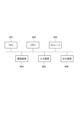
- FIG. 2 is a diagram illustrating the functional blocks of the unmanned aerial vehicle.
- FIG. 3 is a flowchart illustrating the operation assistance method.
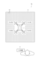
- FIG. 4 is a diagram illustrating a system configuration of an operation assistance system according to a modified example.
- FIG. 5 is a flowchart illustrating an operation assistance method according to a modified example.
- FIG. 6 is a diagram for explaining the hardware configuration of a computer used in the operation support system.
- the operation assistance system 5 assists in the landing of the unmanned aerial vehicle 1.
- the operation assistance system 5 includes the unmanned aerial vehicle 1, an input device 2, and a grounding unit 3.
- Unmanned aerial vehicle 1 is an aircraft that does not have a human on board. Unmanned aerial vehicle 1 is driven by instructions inputted from an input device 2 or the like using radio waves or the like. Unmanned aerial vehicle 1 is, for example, a drone.
- the unmanned aerial vehicle 1 is shown as viewed from above.
- the unmanned aerial vehicle 1 has four legs 11a, 11b, 11c, and 11d. When there is no need to distinguish between the four legs 11a, 11b, 11c, and 11d, they may simply be referred to as legs 11. Note that the number of legs 11 provided on the unmanned aerial vehicle 1 does not have to be four, and may be three or less, or five or more.
- each leg 11 is equipped with an electromagnet 111 as shown in FIG. 2.
- the electromagnet 111 is energized according to instructions from the control unit 10 and becomes a magnet.
- the input device 2 is a device for inputting instructions to operate the unmanned aerial vehicle 1.
- the input device 2 is operated by a person, such as an operator of the unmanned aerial vehicle 1.
- the input device 2 is, for example, a remote controller.
- the input device 2 may also have a function for acquiring and displaying data indicating the status of the unmanned aerial vehicle 1.
- the ground contact portion 3 is the portion where each leg 11 of the unmanned aerial vehicle 1 comes into contact with the ground.
- the ground contact portion 3 is preferably flat, but may also include non-flat portions, such as curved surfaces, or uneven portions.
- the grounding portion 3 has a magnetic material.
- the grounding portion 3 is formed so that when the legs 11 of the unmanned aerial vehicle 1 approach within a predetermined distance, the electromagnets 111 of the legs 11 that are energized are attracted to the grounding portion 3.
- the magnetic material of the grounding portion 3 may be formed in any manner.
- the unmanned aerial vehicle 1 comprises a control unit 10, four legs 11a, 11b, 11c, and 11d, and four rotor units 12a, 12b, 12c, and 12d.
- rotor units 12a, 12b, 12c, and 12d When there is no need to distinguish between the four rotor units 12a, 12b, 12c, and 12d, they may simply be referred to as rotor units 12.
- the four rotor units 12a, 12b, 12c, and 12d are provided corresponding to the four legs 11a, 11b, 11c, and 11d, respectively.
- one rotor unit 12 is provided on one leg 11, such as rotor unit 12a being provided on leg 11a.
- one rotor unit 12 may be provided on multiple legs 11, or multiple rotor units 12 may be provided on one leg 11.
- the legs 11 and rotor units 12 do not need to correspond one-to-one, as long as the legs 11 and the rotor units 12 that control them correspond to each other.
- the control unit 10 controls each part of the unmanned aerial vehicle 1.
- the control unit 10 controls each part by acquiring data from each part, changing or driving the settings of each part, etc.
- the control unit 10 issues instructions to drive the legs 11 and rotor unit 12, for example, and receives detection from the sensor 112 of the legs 11.
- the control unit 10 may control each part of the unmanned aerial vehicle 1 according to instructions from the input device 2, or may control each part according to input data.
- the control unit 10 activates the electromagnet 111 when any of the legs 11 touches the ground.
- the control unit 10 stops the electromagnets of each leg 11 when all of the legs 11 touch the ground.
- touching the ground includes not only the timing when any of the legs 11 touches the ground part 3, but also the timing when they come within a predetermined distance of the ground part 3.
- the control unit 10 activates the electromagnet 111, for example, when the sensor 112 described below detects grounding or approach. Alternatively, when the operator detects grounding or approach through visual inspection, the operator inputs the grounding or approach into the input device 2. When the control unit 10 is notified of grounding or approach from the input device 2, it activates the electromagnet 111.
- the electromagnet 111 When the control unit 10 touches down on any of the legs 11, the electromagnet 111 is activated, and each leg 11 is then attracted to the grounding part 3, which has a magnetic material. This allows the unmanned aerial vehicle 1 to land safely. Additionally, the burden on the operator is reduced by having the legs 11 attracted to the grounding part 3 regardless of the operation from the input device 2.
- Each leg 11 is equipped with an electromagnet 111 and a sensor 112.
- the electromagnet 111 is driven according to instructions from the control unit 10. Normally, the electromagnet 111 does not generate magnetic force, but when electricity is applied in response to instructions from the control unit 10, it generates magnetic force.
- the sensor 112 detects the contact or approach of the provided leg 11 to the grounding part 3. When the sensor 112 detects the contact or approach, it notifies the control unit 10. When the sensor 112 detects the contact or approach, the control unit 10 activates the electromagnet 111.
- the sensor 112 further detects a leg that has touched or is approaching the grounding portion 3. For example, when the leg 11a on which the sensor 112 is provided touches the grounding portion 3, the sensor 112 notifies the control unit 10 of the identifier of the grounded leg 11. When the leg 11a on which the sensor 112 is provided approaches the grounding portion 3 within a predetermined distance, the sensor 112 may notify the control unit 10 of the identifier of the grounded leg 11.
- the senor 112 is described as being provided on each leg 11, but this is not limited to the above.
- the sensor 112 only needs to be able to detect the contact of any of the legs 11 with the ground or the approach of the grounding portion 3.
- a single sensor may be used to detect the contact of each leg 11 with the grounding portion 3.
- the rotor unit 12 is driven according to instructions from the control unit 10.
- the rotor unit 12 includes a rotor and a motor.
- the rotor unit 12 drives the motor to rotate the rotor in either the positive or negative direction.
- the rotor unit 12 controls the attitude of the unmanned aerial vehicle 1. For example, when the unmanned aerial vehicle 1 takes off, the rotor unit 12 drives the motor to rotate the rotor in the positive direction, and when it stops, rotates the rotor in the negative direction.
- the control unit 10 rotates the rotors corresponding to the legs 11 other than the leg 11 that has touched the ground or is approaching in the sinking direction. For example, a case will be described in which the sensor 112 detects that the leg 11a has touched the ground portion 3.
- the control unit 10 outputs an instruction to rotate the rotors corresponding to the legs 11 other than the leg 11a in the sinking direction.
- the legs 11 other than the leg 11a are any one or more of the legs 11b, 11c, and 11d.
- the rotors corresponding to the legs 11 other than the leg 11a are the rotor parts 12 of the rotor parts 12b, 12c, and 12d that correspond to any one or more of the legs 11c and 11d.
- the control unit 10 may rotate, in a sinking direction, the rotor corresponding to the leg 11 on the opposite side of the center of gravity of the unmanned aerial vehicle 1 from the leg 11 that has landed on the ground or is approaching, among the rotors corresponding to the leg 11 other than the leg 11 that has landed on the ground or is approaching.
- the center of the unmanned aerial vehicle 1 is considered to be the center of the fuselage of the unmanned aerial vehicle 1.
- leg 11d When leg 11a has landed on the ground, the leg 11 on the opposite side of the unmanned aerial vehicle 1 with respect to reception is leg 11d.
- the control unit 10 outputs an instruction to rotate the rotor corresponding to leg 11d, specifically the rotor of rotor portion 12d, in a sinking direction.
- the leg 11 on the opposite side of the unmanned aerial vehicle 1's center of gravity is considered to be far away from the ground 3. Therefore, the leg 11 on the opposite side of the unmanned aerial vehicle 1's center of gravity is moved downward by the rotor, allowing the unmanned aerial vehicle 1 to land stably.
- the control unit 10 may maximize the rotor output of the leg 11 on the opposite side that is the furthest from the leg 11 that has touched the ground or is close to it.
- the leg 11 on the opposite side that has touched the ground or is close to it is leg 11d.
- the control unit 10 outputs an instruction to leg 11d to drive the rotor with the largest output, and outputs an instruction to the other legs 11 to drive the rotor with an output smaller than that of leg 11d.
- step S101 when the control unit 10 detects that any of the legs 11 of the unmanned aerial vehicle 1 has landed on or approached the grounding portion 3, the control unit 10 proceeds to step S102.
- step S102 the control unit 10 outputs an instruction to activate the electromagnets 111 of each leg 11 of the unmanned aerial vehicle 1.
- the electromagnets 111 of the legs 11 generate magnetic force. This makes it easier for the legs 11 to be attracted to the grounding portion 3.
- step S103 the control unit 10 outputs an instruction to rotate the rotors corresponding to the legs 11 other than the legs 11 that are in contact with the grounding part 3 in the sinking direction. This makes it easier for the unmanned aerial vehicle 1 to approach the grounding part 3.
- the operation assistance system 5 allows the unmanned aerial vehicle 1 to land safely. Specifically, even in poor conditions, such as when landing in a crosswind or on a sloping surface, rollover when one foot is on the ground is prevented, and a stable landing is achieved.
- An operation assistance system 5a according to a modified example will be described with reference to Fig. 4.
- the operation assistance system 5a is different from the operation assistance system 5 shown in Fig. 1 in the specifications of the ground contact portion 3a.
- the grounded portion 3a has an array of electromagnet cells 31 on the grounded surface.
- the electromagnet cells 31 are drawn only around the grounded portion 3a, but electromagnet cells 31 are also provided around the unmanned aerial vehicle 1.
- the legs 11 of the unmanned aerial vehicle 1 have a magnetic material that can be attracted to the energized electromagnet cell 31.
- the ground contact portion 3a is also provided with a sensor (not shown).
- the sensor detects when any of the legs 11 of the unmanned aerial vehicle 1 touches or approaches the ground contact portion 3a.
- the grounded portion 3a further includes a control unit (not shown) that controls the electromagnet cell 31 and the sensor.
- the control unit may be provided anywhere as long as it is capable of controlling the electromagnet cell 31 and the sensor.
- the control unit may be built into the grounded portion 3a, or may be implemented in a computer connected to the grounded portion 3a.
- the control unit of the unmanned aerial vehicle 1 may also control the electromagnet cell 31 and the sensor of the grounded portion 3a.
- the control unit activates the multiple electromagnet cells 31.
- the legs 11 of the unmanned aerial vehicle 1 are attracted to the grounding portion 3a.
- the control unit may also control each part of the unmanned aerial vehicle 1. For example, the control unit may output an instruction to rotate the rotors corresponding to the legs 11 other than the leg 11 that is in contact with the grounding portion 3a in the sinking direction.
- step S201 when the control unit detects that one of the legs 11 of the unmanned aerial vehicle 1 has landed on or approached the grounding portion 3, the control unit proceeds to step S202.
- step S202 the control unit 10 outputs an instruction to activate the electromagnet cell 31 of the grounding portion 3a.
- the electromagnet cell 31 of the grounding portion 3a generates a magnetic force. This makes it easier for the leg 11 to be attracted to the grounding portion 3a.
- step S203 the control unit outputs an instruction to rotate the rotors corresponding to the legs 11 other than the leg 11 that is in contact with the grounding portion 3a in the sinking direction. This makes it easier for the unmanned aerial vehicle 1 to approach the grounding portion 3a.
- the operation assistance system 5 allows the unmanned aerial vehicle 1 to land safely.
- the control unit of the present embodiment described above is, for example, a general-purpose computer system equipped with a CPU (Central Processing Unit, processor) 901, memory 902, storage 903 (HDD: Hard Disk Drive, SSD: Solid State Drive), communication device 904, input device 905, and output device 906.
- the CPU 901 executes a program loaded on the memory 902, thereby realizing each function of the control unit.
- the control unit may be implemented in one computer, or in multiple computers.
- the control unit may also be a virtual machine implemented in a computer.
- the control unit program can be stored on a computer-readable recording medium such as a HDD, SSD, USB (Universal Serial Bus) memory, CD (Compact Disc), or DVD (Digital Versatile Disc), or can be distributed via a network.
- a computer-readable recording medium such as a HDD, SSD, USB (Universal Serial Bus) memory, CD (Compact Disc), or DVD (Digital Versatile Disc), or can be distributed via a network.
- the computer-readable recording medium is, for example, a non-transitory recording medium.
Landscapes
- Engineering & Computer Science (AREA)
- Aviation & Aerospace Engineering (AREA)
- Mechanical Engineering (AREA)
- Remote Sensing (AREA)
- Forklifts And Lifting Vehicles (AREA)
Abstract
無人航空機1は、各脚部11に備えられた電磁石111と、いずれかの脚部11の接地時に、電磁石111を起動する制御部10を備え、電磁石111が起動した後、各脚部11が、磁性体を有する接地部3に吸着する。
Description
本開示は、無人航空機、操作支援システムおよび操作支援方法に関する。
ドローンなどの無人航空機(UAV:UNMANNED AERIAL VEHICLE)の制御において、着地が困難な場合がある。特に、横風時の着地、または傾斜地への着地など、環境によっては、着地の難易度がさらに高くなる場合がある。また一旦着地した後に、風で煽られるなどにより、無人航空機が横転する場合もある。
無人航空機の確実な着陸方法として、ハンドキャッチがある(非特許文献1)。ハンドキャッチでは、操作者が無人航空機の脚をつかむことにより、無人航空機を停止する。ハンドキャッチでは、機体に対して安全な着陸が困難な場面において、使われる。
吉武 穂高、"(phantom4)ドローンを『ハンドキャッチ』するメリットとは?"、[online]、2016年7月20日、ガジェットウォーカー、[2023年6月28日検索]、インターネット〈URL:https://drone-aerial-corps.com/2016/07/20/hand-katch/〉
しかしながら、飛行時の姿勢安定のための機能が、意図せず働く場合がある。この機能により、ロータの力によって、機体が横転する場合もある。またハンドキャッチ可能な無人航空機のサイズに制約がある。またハンドキャッチによる操作者の怪我のリスクが、ある。
本開示は、上記事情に鑑みてなされたものであり、本開示の目的は、無人航空機を安全に着陸可能な技術を提供することである。
本開示の一態様の無人航空機は、各脚部に備えられた電磁石と、いずれかの脚部の接地時に、前記電磁石を起動する制御部を備え、前記電磁石が起動した後、各脚部が、磁性体を有する接地部に吸着する。
本開示の一態様の操作支援システムは、無人航空機と、磁性体を有する接地部と、を備え、前記無人航空機は、各脚部に備えられた電磁石と、いずれかの脚部の接地時に、前記電磁石を起動する制御部を備え、前記電磁石が起動した後、各脚部が、前記接地部に吸着する。
本開示の一態様の操作支援方法は、無人航空機が備える各脚部のうちのいずれかの脚部が、磁性体を有する接地部に接地し、いずれかの脚部が、前記接地部に接地または接近した後、各脚部に備えられた電磁石が、起動し、前記電磁石が起動した後、各脚部が、前記接地部に吸着する。
本開示の一態様の操作支援システムは、無人航空機の接地部に設けられた複数の電磁石セルと前記無人航空機の各脚部のいずれかの、前記接地部への接地または接近を検出するセンサと、前記センサが、前記脚部の前記接地部への接地または接近を検知すると、前記複数の電磁石セルを起動する制御部を備え、前記複数の電磁石セルが起動すると、前記無人航空機の脚部が、前記接地部に吸着する。
本開示によれば、無人航空機を安全に着陸可能な技術を提供することができる。
以下、図面を参照して、本開示の実施の形態を説明する。図面の記載において同一部分には同一符号を付し説明を省略する。
(操作支援システム)
図1に示す操作支援システム5は、無人航空機1の着陸を支援する。操作支援システム5は、無人航空機1、入力装置2および接地部3を有する。
図1に示す操作支援システム5は、無人航空機1の着陸を支援する。操作支援システム5は、無人航空機1、入力装置2および接地部3を有する。
無人航空機1は、人が搭乗しない航空機である。無人航空機1は、入力装置2などから無線電波などを使って入力される指示により駆動する。無人航空機1は、例えば、ドローンである。
図1に示す例において無人航空機1は上面視で示される。無人航空機1は、4つの脚部11a、11b、11cおよび11dを備える。4つの脚部11a、11b、11cおよび11dのそれぞれを区別しない場合、単に、脚部11と記載される場合がある。なお、無人航空機1が備える脚部11の数は、4つでなくてもよく、3つ以下または5つ以上でも良い。
本開示において、各脚部11は、図2に示すように電磁石111を備える。電磁石111は、制御部10からの指示に従って通電され、磁石となる。
入力装置2は、無人航空機1を操作する指示を入力する装置である。入力装置2は、例えば、無人航空機1のオペレータ等の人によって操作される。入力装置2は、例えば、リモートコントローラである。入力装置2は、無人航空機1の状態を示すデータを取得し、表示する機能を備えても良い。
接地部3は、無人航空機1の各脚部11が接地する部分である。接地部3は、平面であることが好ましいが、曲面など、平面でない部分、または凹凸部分を含んでも良い。
本開示において接地部3は、磁性体を有する。接地部3は、無人航空機1の脚部11が所定距離内に近づくと、脚部11の通電中の電磁石111が吸着するように形成される。接地部3の磁性体は、どのように形成されても良い。
図2を参照して、本開示に係る無人航空機1を説明する。無人航空機1は、制御部10、4つの脚部11a、11b、11cおよび11d、および4つのロータ部12a、12b、12cおよび12dを備える。4つのロータ部12a、12b、12cおよび12dを区別しない場合、単に、ロータ部12と記載される場合がある。
本開示において4つのロータ部12a、12b、12cおよび12dのそれぞれは、4つの脚部11a、11b、11cおよび11dに対応して設けられる。本開示では図1に示すように、脚部11aにロータ部12aが設けられるなど、1つの脚部11に1つのロータ部12が設けられる。他の実施例では、複数の脚部11に1つのロータ部12が設けられる、1つの脚部11に複数のロータ部12が設けられる場合があっても良い。脚部11とロータ部12は、1対1に対応しなくても良く、脚部11とその脚部11を制御するロータ部12が対応づけられていれば良い。
制御部10は、無人航空機1が備える各部を制御する。制御部10による各部の制御は、各部からのデータ取得、各部の設定値等の変更または駆動などである。制御部10は、例えば、脚部11およびロータ部12の駆動を指示し。脚部11のセンサ112からの検知を受信する。また制御部10は、入力装置2からの指示に従って、無人航空機1の各部を制御する場合もあれば、入力されるデータに従って制御する場合もある。
本開示において制御部10は、いずれかの脚部11の接地時に、電磁石111を起動する。制御部10は、全ての脚部11が接地するなどのタイミングで、各脚部11の電磁石を停止する。ここで接地時は、脚部11のいずれかが接地部3に接地したタイミングのほか、接地部3に所定距離内に接近したタイミングを含む。
制御部10は、例えば、後述のセンサ112が接地または接近を検知すると、電磁石111を起動する。あるいは、オペレータの目視による確認で接地または接近を検知すると、オペレータは、入力装置2に、接地または接近を入力する。制御部10は、入力装置2から接地または接近が通知されると、電磁石111を起動する。
制御部10が、いずれかの脚部11の接地時に、電磁石111が起動した後、各脚部11が、磁性体を有する接地部3に吸着する。これにより、無人航空機1を安全に着陸させることができる。また、入力装置2からの操作にかかわらず、脚部11が接地部3に吸着することにより、オペレータの負担も軽減される。
脚部11はそれぞれ、電磁石111およびセンサ112を備える。
電磁石111は、制御部10からの指示に従って駆動する。電磁石111は、通常時は磁力を発しないが、制御部10からの指示によって通電され、磁力を発生する。
センサ112は、設けられた脚部11の接地部3への接地または接近を検知する。センサ112は、接地または接近を検知すると、制御部10に通知する。制御部10は、センサ112が接地または接近を検知すると、電磁石111を起動する。
センサ112は、さらに、接地部3に接地または接近した脚部を検知する。例えばセンサ112は、センサ112が設けられた脚部11aが接地部3に接地すると、制御部10に、接地した脚部11の識別子を通知する。センサ112は、センサ112が設けられた脚部11aが接地部3に所定距離内に接近すると、制御部10に、接地した脚部11の識別子を通知しても良い。
本開示においてセンサ112は、各脚部11に設けられる場合を説明するが、これに限らない。センサ112は、いずれかの脚部11の接地または接地部3への接近を検知できればよい。例えば、1つのセンサで、各脚部11のそれぞれの接地部3への接地または接近を検知しても良い。
ロータ部12は、制御部10からの指示に従って駆動する。ロータ部12は、ロータとモータを備える。制御部10からの指示によって、ロータ部12は、モータを駆動し、正負のいずれかの方向にロータを回転する。ロータ部12は、無人航空機1の機体姿勢を制御する。ロータ部12は、例えば、無人航空機1の浮上時に、モータを駆動し、正の方向にロータを回転し、停止時に、負の方向にロータを回転する。
制御部10は、センサ112が接地、または接近を検知すると、接地または接近した脚部11以外の脚部11に対応するロータを、沈下方向に回転する。例えば、センサ112が、脚部11aが接地部3に接地したことを検知する場合を説明する。制御部10は、脚部11a以外の脚部11に対応するロータを、沈下方向に回転する指示を出力する。本開示において脚部11a以外の脚部11は、脚部11b、脚部11cおよび脚部11dのうちのいずれか1つ以上である。脚部11a以外の脚部11に対応するロータは、ロータ部12b、ロータ12部cおよびロータ部12dのうち、脚部11cおよび脚部11dのうちのいずれか1つ以上に対応するロータ部12である。
脚部11が接地した際、接地した脚部11の反対側の脚部11に対応するロータを沈下方向に駆動する。これにより、無人航空機1を着地面に押しつけ、安定して着地することができる。
制御部10は、接地または接近した脚部11以外の脚部11に対応するロータのうち、接地または接近した脚部11から、無人航空機1の重心に対して反対側の脚部11対応するロータを、沈下方向に回転しても良い。図1に示す例において、無人航空機1の中心は、無人航空機1の胴体の中心と考えられる。脚部11aが接地した場合、無人航空機1の受信に対して反対側の脚部11は、脚部11dである。制御部10は、脚部11dに対応するロータ、具体的にはロータ部12dのロータを、沈下方向に回転する指示を出力する。
ある脚部11が接地部に接地した際、無人航空機1の重心に対して反対側の脚部11は、接地部3に対して大きく離れていると考えられる。そこで、無人航空機1の重心に対して反対側の脚部11が、ロータにより沈下方向に移動することで、無人航空機1は、安定的に着陸することができる。
制御部10は、反対側の脚部11のうち、接地または接近した脚部11から最も離れた脚部11のロータの出力を最大としても良い。図1に示す例において、反対側の脚部11のうち、接地または接近した脚部11は、脚部11dとなる。制御部10は、脚部11dに最も大きい出力でロータを駆動する指示を出力し、それ以外の脚部11に、脚部11dの出力よりも小さい出力でロータを駆動する指示を出力する。
ある脚部11が接地部3に接地した際、接地した脚部11の反対側の脚部11のうち、接地または接近した脚部11から最も離れた脚部11は、接地部3に対して大きく離れていると考えられる。そこで、接地または接近した脚部11から最も離れた脚部11が、ロータにより沈下方向に移動することで、無人航空機1は、安定的に着陸することができる。
図3を参照して、本開示に係る操作支援方法を説明する。
ステップS101において制御部10は、無人航空機1のいずれかの脚部11が接地部3に接地または接近したことを検知すると、ステップS102に進む。ステップS102において制御部10は、無人航空機1の各脚部11の電磁石111を起動する指示を出力する。脚部11の電磁石111は、磁力を発生する。これにより、脚部11が接地部3に吸着されやすくなる。
ステップS103において制御部10は、接地部3に接地した脚部11以外の脚部11に対応するロータを、沈下方向に回転する指示を出力する。これにより、無人航空機1が接地部3に近づきやすくなる。
このような本開示に係る操作支援システム5によれば、無人航空機1を安全に着陸させることができる。具体的には、横風時の着陸、傾斜地盤への着陸など、条件の悪い状況における着陸においても、片脚接地での横転などを防ぎ、安定した着陸が実現される。
(変形例)
図4を参照して、変形例に係る操作支援システム5aを説明する。操作支援システム5aは、図1に示す操作支援システム5と比べて、接地部3aの仕様が異なる。
図4を参照して、変形例に係る操作支援システム5aを説明する。操作支援システム5aは、図1に示す操作支援システム5と比べて、接地部3aの仕様が異なる。
接地部3aは、接地面に、アレイ状の電磁石セル31を設ける。図4に示す例では、図面描画の都合上接地部3aの周囲にのみ電磁石セル31が描画されるが、無人航空機1の周辺にも、電磁石セル31が設けられる。
なお、変形例において無人航空機1の脚部11は、通電された電磁石セル31に吸着可能な磁性体を有する。
また、接地部3aは、センサ(図示せず)を設ける。センサは、無人航空機1の各脚部11のいずれかの、接地部3aへの接地または接近を検出する。
接地部3aは、さらに、電磁石セル31およびセンサを制御する制御部(図示せず)を備える。制御部は、電磁石セル31およびセンサを制御可能であれば、どこに設けられても良い。制御部は、接地部3aに内蔵されても良いし、接地部3aに接続するコンピュータに実装されても良い。また無人航空機1の制御部が、接地部3aの電磁石セル31およびセンサを制御しても良い。
制御部は、センサが、脚部11の接地部3aへの接地または接近を検知すると、複数の電磁石セル31を起動する。複数の電磁石セル31が起動すると、無人航空機1の脚部11が、接地部3aに吸着する。
また制御部は、無人航空機1の各部を制御しても良い。制御部は、例えば、接地部3aに接地した脚部11以外の脚部11に対応するロータを、沈下方向に回転する指示を出力しても良い。
図5を参照して、本開示に係る操作支援方法を説明する。
ステップS201において制御部は、無人航空機1のいずれかの脚部11が接地部3に接地または接近したことを検知すると、ステップS202に進む。ステップS202において制御部10は、接地部3aの電磁石セル31を起動する指示を出力する。接地部3aの電磁石セル31は、磁力を発生する。これにより、脚部11が接地部3aに吸着されやすくなる。
ステップS203において制御部は、接地部3aに接地した脚部11以外の脚部11に対応するロータを、沈下方向に回転する指示を出力する。これにより、無人航空機1が接地部3aに近づきやすくなる。
このような変形例に係る操作支援システム5によれば、無人航空機1を安全に着陸させることができる。
上記説明した本実施形態の制御部は、例えば、CPU(Central Processing Unit、プロセッサ)901と、メモリ902と、ストレージ903(HDD:Hard Disk Drive、SSD:Solid State Drive)と、通信装置904と、入力装置905と、出力装置906とを備える汎用的なコンピュータシステムが用いられる。このコンピュータシステムにおいて、CPU901がメモリ902上にロードされたプログラムを実行することにより、制御部の各機能が実現される。
なお、制御部は、1つのコンピュータで実装されてもよく、あるいは複数のコンピュータで実装されても良い。また制御部は、コンピュータに実装される仮想マシンであっても良い。
制御部のプログラムは、HDD、SSD、USB(Universal Serial Bus)メモリ、CD (Compact Disc)、DVD (Digital Versatile Disc)などのコンピュータ読取り可能な記録媒体に記憶することも、ネットワークを介して配信することもできる。コンピュータ読取り可能な記録媒体は、例えば非一時的な(non-transitory)記録媒体である。
なお、本開示は上記実施形態に限定されるものではなく、その要旨の範囲内で数々の変形が可能である。
1 無人航空機
2 入力装置
3 接地部
5 操作支援システム
10 制御部
11 脚部
12 ロータ部
111 電磁石
112 センサ112
901 CPU
902 メモリ
903 ストレージ
904 通信装置
905 入力装置
906 出力装置
2 入力装置
3 接地部
5 操作支援システム
10 制御部
11 脚部
12 ロータ部
111 電磁石
112 センサ112
901 CPU
902 メモリ
903 ストレージ
904 通信装置
905 入力装置
906 出力装置
Claims (8)
- 各脚部に備えられた電磁石と、
いずれかの脚部の接地時に、前記電磁石を起動する制御部を備え、
前記電磁石が起動した後、各脚部が、磁性体を有する接地部に吸着する
無人航空機。 - 各脚部のいずれかの、前記接地部への接地または接近を検知するセンサを有し、
前記制御部は、前記センサが接地または接近を検知すると、前記電磁石を起動する
請求項1に記載の無人航空機。 - 前記各脚部に対応するロータを備え、
前記センサは、さらに、前記接地部に接地または接近した脚部を検知し、
前記制御部は、前記センサが検知すると、前記接地または接近した脚部以外の脚部に対応するロータを、沈下方向に回転する
請求項2に記載の無人航空機。 - 前記制御部は、前記接地または接近した脚部から、前記無人航空機の重心に対して反対側の脚部に対応するロータを、沈下方向に回転する
請求項3に記載の無人航空機。 - 前記制御部は、反対側の脚部のうち、前記接地または接近した脚部から最も離れた脚部のロータの出力を最大とする
請求項3に記載の無人航空機。 - 無人航空機と、
磁性体を有する接地部と、を備え、
前記無人航空機は、
各脚部に備えられた電磁石と、
いずれかの脚部の接地時に、前記電磁石を起動する制御部を備え、
前記電磁石が起動した後、各脚部が、前記接地部に吸着する
操作支援システム。 - 無人航空機が備える各脚部のうちのいずれかの脚部が、磁性体を有する接地部に接地し、
いずれかの脚部が、前記接地部に接地または接近した後、各脚部に備えられた電磁石が、起動し、
前記電磁石が起動した後、各脚部が、前記接地部に吸着する
操作支援方法。 - 無人航空機の接地部に設けられた複数の電磁石セルと
前記無人航空機の各脚部のいずれかの、前記接地部への接地または接近を検出するセンサと、
前記センサが、前記脚部の前記接地部への接地または接近を検知すると、前記複数の電磁石セルを起動する制御部
を備え、
前記複数の電磁石セルが起動すると、前記無人航空機の脚部が、前記接地部に吸着する操作支援システム。
Priority Applications (1)
| Application Number | Priority Date | Filing Date | Title |
|---|---|---|---|
| PCT/JP2023/025101 WO2025009148A1 (ja) | 2023-07-06 | 2023-07-06 | 無人航空機、操作支援システムおよび操作支援方法 |
Applications Claiming Priority (1)
| Application Number | Priority Date | Filing Date | Title |
|---|---|---|---|
| PCT/JP2023/025101 WO2025009148A1 (ja) | 2023-07-06 | 2023-07-06 | 無人航空機、操作支援システムおよび操作支援方法 |
Publications (1)
| Publication Number | Publication Date |
|---|---|
| WO2025009148A1 true WO2025009148A1 (ja) | 2025-01-09 |
Family
ID=94171334
Family Applications (1)
| Application Number | Title | Priority Date | Filing Date |
|---|---|---|---|
| PCT/JP2023/025101 Ceased WO2025009148A1 (ja) | 2023-07-06 | 2023-07-06 | 無人航空機、操作支援システムおよび操作支援方法 |
Country Status (1)
| Country | Link |
|---|---|
| WO (1) | WO2025009148A1 (ja) |
Citations (3)
| Publication number | Priority date | Publication date | Assignee | Title |
|---|---|---|---|---|
| CN210592475U (zh) * | 2019-09-28 | 2020-05-22 | 重庆联盛建设项目管理有限公司 | 基于无人机的桥梁质量监管装置 |
| CN108688798B (zh) * | 2017-04-11 | 2020-11-06 | 北京乐普盛通信息技术有限公司 | 飞行器辅助起降装置及其降落与起飞控制方法 |
| CN216684823U (zh) * | 2022-05-05 | 2022-06-07 | 海伯利安(成都)航空科技有限公司 | 一种无人飞行器 |
-
2023
- 2023-07-06 WO PCT/JP2023/025101 patent/WO2025009148A1/ja not_active Ceased
Patent Citations (3)
| Publication number | Priority date | Publication date | Assignee | Title |
|---|---|---|---|---|
| CN108688798B (zh) * | 2017-04-11 | 2020-11-06 | 北京乐普盛通信息技术有限公司 | 飞行器辅助起降装置及其降落与起飞控制方法 |
| CN210592475U (zh) * | 2019-09-28 | 2020-05-22 | 重庆联盛建设项目管理有限公司 | 基于无人机的桥梁质量监管装置 |
| CN216684823U (zh) * | 2022-05-05 | 2022-06-07 | 海伯利安(成都)航空科技有限公司 | 一种无人飞行器 |
Similar Documents
| Publication | Publication Date | Title |
|---|---|---|
| KR102851268B1 (ko) | 항공기용 전기 동력 추진 시스템 | |
| US10671094B2 (en) | Virtual safety shrouds for aerial vehicles | |
| US11542001B1 (en) | Mechanical vibration based inter-module communication in vehicle | |
| CN112105540A (zh) | 自动驾驶安全交互系统 | |
| TW200835540A (en) | Central control system of wireless remote-control model | |
| US20190190408A1 (en) | Electric speed controller, flight controller, and control method and control system of unmanned aerial vehicle | |
| CN105940375B (zh) | 针对多操作系统设备的动态再分配 | |
| CN104843178A (zh) | 飞行摩托车或汽车及其飞行姿态调整方法 | |
| WO2023025200A1 (zh) | 一种无人机迫降控制方法及装置、遥控装置和存储介质 | |
| CN111806676A (zh) | 混合多旋翼载具和相关方法 | |
| EP3150489A1 (en) | Unified control of multiple active systems for helicopter vibration supression | |
| CN105556409A (zh) | 一种飞行器控制方法、装置及飞行器 | |
| WO2017203590A1 (ja) | 飛行体の飛行システム、及び飛行体の飛行方法 | |
| CN107251280A (zh) | 动态改变电池的内部状态 | |
| CN111942188A (zh) | 一种无人机空中充电系统、充电方法、装置、设备和介质 | |
| WO2025009148A1 (ja) | 無人航空機、操作支援システムおよび操作支援方法 | |
| CN115485194B (zh) | 节省uav能量消耗和提高其悬停精度的方法 | |
| US11936214B2 (en) | Wireless charging of an electric aircraft | |
| US20170316712A1 (en) | Aircraft Procedural Trainer Interface | |
| CN104590552A (zh) | 基于视觉导航的微型多旋翼飞行器 | |
| CN107168044A (zh) | 一种水下机器人推进器容错系统 | |
| CN104865961A (zh) | 控制方法、装置及电子设备 | |
| US11685274B1 (en) | Connector for charging an electric aircraft and a method for its use | |
| CN114802796A (zh) | 一种柱状旋翼无人机弹射装置及其弹射方法 | |
| US20220197307A1 (en) | Landing a vertical landing vehicle |
Legal Events
| Date | Code | Title | Description |
|---|---|---|---|
| 121 | Ep: the epo has been informed by wipo that ep was designated in this application |
Ref document number: 23944396 Country of ref document: EP Kind code of ref document: A1 |
|
| NENP | Non-entry into the national phase |
Ref country code: DE |