WO2025005247A1 - バッテリケース評価システム、バッテリケース評価プログラム、及び、バッテリケース評価方法 - Google Patents
バッテリケース評価システム、バッテリケース評価プログラム、及び、バッテリケース評価方法 Download PDFInfo
- Publication number
- WO2025005247A1 WO2025005247A1 PCT/JP2024/023511 JP2024023511W WO2025005247A1 WO 2025005247 A1 WO2025005247 A1 WO 2025005247A1 JP 2024023511 W JP2024023511 W JP 2024023511W WO 2025005247 A1 WO2025005247 A1 WO 2025005247A1
- Authority
- WO
- WIPO (PCT)
- Prior art keywords
- battery
- battery case
- resistance value
- simulated
- actual
- Prior art date
- Legal status (The legal status is an assumption and is not a legal conclusion. Google has not performed a legal analysis and makes no representation as to the accuracy of the status listed.)
- Ceased
Links
Images




Classifications
-
- Y—GENERAL TAGGING OF NEW TECHNOLOGICAL DEVELOPMENTS; GENERAL TAGGING OF CROSS-SECTIONAL TECHNOLOGIES SPANNING OVER SEVERAL SECTIONS OF THE IPC; TECHNICAL SUBJECTS COVERED BY FORMER USPC CROSS-REFERENCE ART COLLECTIONS [XRACs] AND DIGESTS
- Y02—TECHNOLOGIES OR APPLICATIONS FOR MITIGATION OR ADAPTATION AGAINST CLIMATE CHANGE
- Y02E—REDUCTION OF GREENHOUSE GAS [GHG] EMISSIONS, RELATED TO ENERGY GENERATION, TRANSMISSION OR DISTRIBUTION
- Y02E60/00—Enabling technologies; Technologies with a potential or indirect contribution to GHG emissions mitigation
- Y02E60/10—Energy storage using batteries
Definitions
- the present invention relates to a battery case evaluation system, a battery case evaluation program, and a battery case evaluation method.
- lithium-ion batteries installed in vehicles, etc. have a limited operating temperature range, so it is necessary to control the operating temperature when using them.
- resistors such as metal plates or rods with an internal resistance close to that of a battery are used as simulated batteries, and the thermal behavior of an actual battery is roughly simulated by passing a current with a specified profile through the simulated battery.
- the present invention has been made to solve the above-mentioned problems, and aims to make it possible to simulate the thermal behavior of a battery more accurately than ever before in order to more efficiently evaluate battery cases.
- the battery case evaluation system is a battery case evaluation system for evaluating the thermal characteristics of a battery case constituting a battery pack or a component of the battery case, and is equipped with a simulated battery installed in the battery case for simulating the thermal behavior of a real battery that is a component of the battery pack, a temperature detection means for detecting the simulated battery temperature, which is the temperature of the simulated battery, a power supply device for supplying power to the simulated battery, and a control device for controlling the power supply device, and the control device is characterized in that it has a parameter reception unit for receiving an input profile indicating the change over time in the current, voltage, or power supplied to the real battery as one of the evaluation parameters, a resistance value calculation unit for calculating the resistance value of the real battery that changes over time based on the simulated battery temperature and the input profile, and a supply power control unit for controlling the power supply device using the resistance value calculated by the resistance value calculation unit.
- the resistance value of the real battery which changes over time, is calculated based on the simulated battery temperature and the input profile, and the power supply device is controlled using the calculated resistance value. Therefore, the thermal behavior of the real battery can be accurately simulated while taking into account the resistance value of the real battery, which changes from moment to moment, and the battery case can be efficiently evaluated. Furthermore, by using a simulated battery, the risk of fire that may occur when using a real battery (for example, damage to the electrode part due to impact when handling the real battery, or fire that may occur if the battery is accidentally overcharged) can be avoided.
- the thermal behavior of the actual battery includes the heat generation behavior of the actual battery and/or the heat absorption behavior of the actual battery.
- control device further has an SOC calculation unit that calculates the SOC of the actual battery that changes over time based on the input profile, and the resistance value calculation unit calculates the resistance value of the actual battery using the SOC calculated by the SOC calculation unit in addition to the simulated battery temperature and the input profile.
- the resistance value of the real battery is calculated while taking into consideration the ever-changing SOC of the real battery, so that the thermal behavior of the real battery can be simulated with higher accuracy. Furthermore, since the SOC is calculated based on the input profile, it is possible to eliminate the need for a process of repeatedly charging and discharging the actual battery to create SOCs under various conditions.
- the parameter receiving unit receives a battery capacity of the actual battery, and the SOC calculation unit calculates an SOC that changes over time using the input profile and the battery capacity. This makes it possible to simulate the thermal behavior of actual batteries with various battery capacities.
- the parameter receiving unit receives, in addition to the input profile, at least one of an initial SOC of the real battery and a SOH of the real battery as the evaluation parameter. This allows the thermal behavior of a real battery to be simulated under a variety of operating conditions.
- implementations for calculating the resistance value of an actual battery include an implementation in which the resistance value calculation unit has a conversion table for converting the evaluation parameters received by the parameter reception unit into resistance values, or a simulation model that uses the evaluation parameters received by the parameter reception unit to output resistance values.
- control device further includes an entropy change calculation unit that calculates the entropy change that occurs due to charging and discharging of the real battery, and the supply power control unit controls the power supply device using the resistance value calculated by the resistance value calculation unit and the entropy change calculated by the entropy change calculation unit.
- the thermal behavior of the battery can be more accurately simulated by taking into account the reaction heat caused by charging and discharging in addition to Joule heat.
- a specific embodiment for calculating the entropy change of the actual battery is one in which the entropy change calculation unit calculates the entropy change using table data or calculation formula data for converting the SOC calculated by the SOC calculation unit into the entropy change occurring in the actual battery.
- the simulated battery has a heating element to which power is supplied from the power supply device, and a thermal diffuser that holds the heating element and diffuses heat generated by the heating element, and at least one of the heating element or the thermal diffuser is formed in a predetermined pattern that can reproduce the surface temperature distribution of the actual battery.
- the phrase "capable of reproducing the surface temperature distribution” used here refers not only to the case where the entire surface temperature distribution can be reproduced, but also to the case where only a portion of the surface temperature distribution can be reproduced. This makes it possible to reproduce various surface temperature distributions of an actual battery, which is useful for simulating thermal behavior such as heat conduction between the battery and surrounding members.
- the heating element or the thermal diffusion element is formed in a predetermined sparse/dense pattern or a predetermined concave/convex pattern. In this way, the simulated battery can be used to simulate the thermal behavior and/or heat diffusion behavior of a real battery.
- the pattern of the heating element or the thermal diffuser is obtained by applying a machine learning model to the surface temperature distribution of the actual battery. In this way, a pattern for obtaining a target surface temperature distribution of the simulated battery can be obtained without using theoretical analysis, which tends to be complicated.
- At least one of the heating element and the thermal diffusion element is preferably formed in a predetermined pattern capable of reproducing the change over time in the surface temperature of the actual battery. In this way, it becomes possible to reproduce the changes over time in various surface temperatures of an actual battery, and it is possible to more accurately simulate thermal behavior, such as thermal conduction between the battery and surrounding members.
- the battery case evaluation program is a battery case evaluation program for evaluating the thermal characteristics of a battery case constituting a battery pack or a component of the battery case, and is used in a battery case evaluation system including a simulated battery installed in the battery case for simulating the thermal behavior of a real battery that is a component of the battery pack, a temperature detection means for detecting the simulated battery temperature, which is the temperature of the simulated battery, a power supply device for supplying power to the simulated battery, and a control device for controlling the power supply device, and is characterized in that the control device is caused to function as a parameter reception unit that receives an input profile indicating the change over time in the current, voltage, or power supplied to the real battery as one of the evaluation parameters, a resistance value calculation unit that calculates the resistance value of the real battery that changes over time based on the simulated battery temperature and the input profile, and a supply power control unit that controls the power supply device using the resistance value calculated by the resistance value calculation unit.
- the battery case evaluation method is a battery case evaluation method for evaluating the thermal characteristics of a battery case constituting a battery pack or a component part of the battery case, and is used together with a battery case evaluation system including a simulated battery installed in the battery case for simulating the thermal behavior of a real battery constituting the battery pack, a temperature detection means for detecting a simulated battery temperature, which is the temperature of the simulated battery, a power supply device for supplying power to the simulated battery, and a control device for controlling the power supply device, and is characterized in that it includes a step of having the control device accept an input profile indicating the change over time in the current, voltage, or power supplied to the real battery as one of the evaluation parameters, a step of having the control device calculate a resistance value of the real battery that changes over time based on the simulated battery temperature and the input profile, and a step of having the control device control the power supply device using the calculated resistance value.
- Such a battery case evaluation program and battery case evaluation method can achieve the same effects as the battery case evaluation system described above.
- the present invention configured in this way, can simulate the thermal behavior of a battery more accurately than ever before, allowing battery cases to be evaluated efficiently.
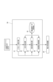
- FIG. 1 is a schematic diagram showing an overall configuration of a battery case evaluation system according to an embodiment of the present invention
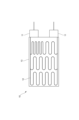
- FIG. 2 is a schematic diagram showing the configuration of a mock battery case according to the embodiment
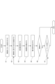
- FIG. 2 is a functional block diagram showing functions of a control device according to the embodiment.
- FIG. 4 is a flowchart showing the operation of the control device according to the embodiment.
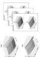
- FIG. 4 is a schematic diagram showing calculation data for the control device of the embodiment.
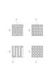
- FIG. 13 is a schematic diagram showing the configuration of a mock battery according to another embodiment.
- FIG. 13 is a schematic diagram showing the configuration of a mock battery according to another embodiment.
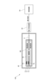
- FIG. 13 is a schematic diagram showing the overall configuration of a battery case evaluation system according to another embodiment.
- FIG. 6 is a flowchart showing the operation of another control device.
- FIG. 11 is a functional block diagram showing functions of a control device according to another embodiment.
- the battery case evaluation system of the present embodiment is intended to evaluate the thermal characteristics of a battery case constituting a battery pack mounted on a vehicle such as an electric vehicle or a hybrid vehicle, or components of the battery case.
- the battery case or the components of the battery case to be evaluated are not necessarily limited to those mounted on vehicles, but may be mounted on various moving bodies such as ships, trains, aircraft, etc. Furthermore, the battery case may be the various moving bodies themselves.
- the battery pack includes, for example, an actual battery (specifically, for example, a lithium ion battery) and a battery case that houses the actual battery.
- the battery case is made up of components such as a reinforcing member such as a frame, a cooling member such as a cooling plate, a heat insulating material that blocks heat from the outside, and/or electronic devices such as a junction box.
- the battery case may include a temperature control device such as a cooling fan that adjusts the temperature of the battery case or battery, and a control device that controls the temperature control device, and the control device may be configured to control the temperature control device according to the temperature of the battery.
- the actual battery may be a single actual cell that is an actual battery cell, or may be an actual battery module consisting of multiple actual cells.
- the battery case evaluation system 100 includes a simulated battery 10, a power supply device 20 that supplies power to the simulated battery 10, and a control device 30 that controls the power supply device 20.
- the simulated battery 10 is intended to simulate the heat generation of a real battery installed in the battery case BC described above, and may be a single simulated cell that simulates a single real cell, or a simulated battery module made up of multiple simulated cells that simulates a real battery module.
- the simulated battery 10 here is a single simulated cell that simulates a single actual cell, and as shown in FIG. 2, has a tab 11 that is connected to a power supply device 20 via wiring, a heating element 12 that receives power from the power supply device 20 via the tab 11, and a thermal diffuser 13 that diffuses the heat generated by the heating element 12.
- the tab 11 is connected to the power supply device 20 via wiring, and is also connected to the heating element 12, for example by welding, and generates heat when power is supplied to it.
- This tab 11 may be the tab 11 itself that is welded to an electrode (negative or positive electrode) that constitutes the actual battery, or it may be one that imitates the shape, material, etc. of the tab 11.
- the heating element 12 generates heat when power is supplied to it, and specifically can be constructed using various heaters such as a linear heater, a sheet heater, or a spot heater.
- the battery case evaluation system 100 of this embodiment further includes a first temperature detection means T1 for detecting the simulated battery temperature, which is the temperature of the simulated battery 10, and a second temperature detection means T2 for detecting the heating element temperature, which is the heating element 12, as shown in FIG. 1.
- the first temperature detection means T1 is provided in the thermal diffuser 13, and the second temperature detection means T2 is provided in the heating element 12.
- the first temperature detection means T1 and the second temperature detection means T2 may each be one or more.
- the average value of the temperature values obtained by the first temperature detection means T1 may be used.
- the advantage of this is that by obtaining the average value of the surface temperature distribution, the surface temperature distribution can be reproduced stably without being biased toward the high temperature side or low temperature side of the temperature distribution. Conversely, for example, when evaluating a surface temperature distribution focusing on a high temperature portion, it is sufficient to provide only one first temperature detection means T1 near the high temperature side.
- At least one of the heating element 12 and the thermal diffusion element 13 is formed in a predetermined pattern that can reproduce the surface temperature distribution of an actual battery, thereby making it possible to reproduce the thermal behavior of an actual battery, and in this case, it is possible to reproduce not only the heat generation behavior of the actual battery but also the heat absorption behavior thereof.
- “capable of reproducing the surface temperature distribution” refers not only to the case where the entire surface temperature distribution can be reproduced, but also to the case where a part of the surface temperature distribution can be reproduced.
- the heating element 12 is formed in a predetermined sparse/dense pattern.
- the heating elements 12 here are linearly arranged in a serpentine manner on the thermal diffuser 13, for example from one tab 11 to the other tab 11, and the surface of the thermal diffuser 13 has areas where the spacing between adjacent heating elements 12 is narrow and areas where the spacing between adjacent heating elements 12 is wide.
- the surface of the thermal diffuser 13 that holds the heating elements 12 has areas where the heating elements 12 are sparsely arranged and areas where the heating elements 12 are densely arranged. With this configuration, the surface temperature of the densely arranged area can be higher than that of the sparsely arranged area.
- the thermal diffuser 13 is not formed in a predetermined pattern, but is, for example, a simple flat plate. However, the thermal diffuser 13 may be formed in a predetermined pattern instead of or in addition to the heating element 12.
- the power supply device 20 receives power instructions from the control device 30 and supplies power to the simulated battery 10 according to the power instructions.
- the power supplied from the power supply device 20 is feedback-controlled by the control device 30, and more specifically, the surface temperature distribution or total heat generation of the simulated battery 10 is feedback-controlled so as to approach the surface temperature distribution or total heat generation of the actual battery.
- the parameter receiving unit 31 receives an input profile indicating the change over time in the current, voltage, or power applied to the actual battery as at least one of the evaluation parameters (S1).
- the evaluation parameters here are parameters required for a simulated battery that is installed in a battery case BC and that simulates the heat generation of an actual battery that is a component of a battery pack, in a battery case evaluation system for evaluating the thermal characteristics of the battery case BC that constitutes a battery pack or the components of the battery case BC, and parameters for simulating the thermal behavior (specifically, heat generation behavior) of the battery case BC or the components of the battery case BC that are the subject of evaluation by this battery case evaluation system 100.
- These evaluation parameters are parameters required to calculate the supply power from the power supply device 20 to the simulated battery 10, and more specifically, are parameters required to obtain the resistance value of the actual battery, which is an unknown quantity when calculating the supply power.
- the resistance value of the real battery fluctuates from moment to moment in accordance with changes in the temperature of the real battery while it is being energized by applying the current, etc., indicated by the input profile described above to the real battery. Therefore, calculating this resistance value is important in calculating the power supply to the simulated battery 10. This is because the power supply to the simulated battery 10 is calculated based on the ratio of the resistance value of the real battery and the resistance value of the simulated battery 10.
- the parameter receiving unit 31 of this embodiment receives an input profile that indicates the change over time in the current applied to the actual battery 10 as at least one of the evaluation parameters.
- This input profile is created in advance by the user and input to the control device 30, and is specifically a current waveform displayed on a graph with one axis representing time and the other axis representing the current value.
- the parameter receiving unit 31 of this embodiment receives at least one of the initial SOC of the real battery and the SOH of the real battery as evaluation parameters in addition to the input profile described above, and here, all of these are received as evaluation parameters.
- SOC indicates the state of charge (State of Charge) of the actual battery
- initial SOC is the SOC in the initial state before power is supplied to the actual battery
- SOH indicates the degradation of the capacity of the actual battery (State of Health).
- the parameter receiving unit 31 receives the battery capacity of the actual battery as a system parameter in addition to the evaluation parameters.
- the parameter receiving unit 31 may receive, as a system parameter, a profile of DCR (dynamic contact resistance) previously acquired based on the above-mentioned input profile, or the resistance value of the heater, which is the above-mentioned heating element 12, in addition to the battery capacity of the simulated battery 10.
- DCR dynamic contact resistance
- Some or all of the evaluation parameters received by the parameter receiving unit 31 described above are output to and stored in the calculation data storage unit 35.
- the SOC calculation unit 32 calculates the SOC of the actual battery, which changes over time, based on the above-mentioned input profile (S2). Note that before calculating this SOC, the simulation time, which is the time when the simulation starts, is initialized.
- the SOC of the real battery changes from moment to moment as current is supplied to the real battery, and the SOC at each moment can be calculated by dividing the integrated value of the supplied current and time by the battery capacity of the real battery.
- the SOC calculation unit 32 is configured to calculate the SOC that changes over time using the input profile and the battery capacity of the actual battery received by the parameter reception unit 31.
- the SOC calculation unit 32 calculates the integrated value of the supply current to the actual battery and time based on the input profile, and divides this integrated value by the battery capacity of the actual battery to calculate the time change rate of the SOC. It then calculates the change in SOC over time using this time change rate and the initial SOC accepted by the parameter acceptance unit 31.
- the SOC calculation unit 32 obtains the calculation formula and coefficients used to calculate the SOC that changes over time from the calculation data storage unit 35.
- the resistance value calculation unit 33 calculates the resistance value of the actual battery that changes over time when a current, voltage, or power based on the input profile is applied to the actual battery (S3).
- the resistance value calculation unit 33 calculates the resistance value using at least the evaluation parameters received by the parameter reception unit 31. Specifically, the resistance value is calculated using the profile of the current supplied to the real battery, the SOC that changes over time calculated by the SOC calculation unit 32, the SOH of the real battery, and the simulated battery temperature detected by the first temperature detection means T1.
- control device 30 of this embodiment further includes a calculation data storage unit 35 that stores calculation data for calculating the SOC, resistance value, and/or supply power.
- the calculation data storage unit 35 stores a conversion table for converting the above-mentioned evaluation parameters into resistance values as calculation data.
- this conversion table is a three-dimensional map with the X-axis, Y-axis, and Z-axis set to simulated battery temperature, real battery resistance, and real battery SOC.
- This three-dimensional map which is a conversion table, is created in advance for each of various SOHs.
- a three-dimensional map for a real battery is created first using a real battery.
- a three-dimensional map for a real battery corresponding to multiple SOHs can be created in advance by preparing real batteries corresponding to multiple SOHs and acquiring the resistance value and SOC of the real battery when the real battery is discharged under specified conditions while changing the temperature of the real battery.
- the three-dimensional map shown in FIG. 5 was created as a three-dimensional map for a simulated battery using a three-dimensional map for a real battery created in advance. Therefore, in the three-dimensional map shown in FIG. 5, the temperature of the real battery is replaced with the temperature of the simulated battery.
- the resistance value calculation unit 33 calculates the resistance value of the actual battery according to the simulated battery temperature detected by the first temperature detection unit T1 and the SOC of the actual battery calculated by the SOC calculation unit 32 at each time, while referring to a three-dimensional map according to the SOH received by the parameter reception unit 31.
- the resistance value of the actual battery calculated in this manner by the resistance value calculation unit 33 is output to the supply power control unit 34.
- the supply power control unit 34 controls the power supply device 20 using the resistance value of the actual battery that changes over time, calculated by the resistance value calculation unit 33.
- the supply power control unit 34 calculates the supply current to be supplied to the simulated battery 10 based on the ratio of the resistance value of the real battery and the resistance value of the simulated battery 10, and the supply current to be supplied to the real battery (i.e., the supply current indicated by the input profile).
- the resistance value of the simulated battery 10 is the resistance value of the heating element 12 to which current is supplied, and when attempting to accurately simulate the total heat generation or surface temperature distribution, the dependence of this resistance value on the temperature of the heating element 12 cannot be ignored, so the supply power control unit 34 obtains the heating element temperature detected by the first temperature detection means T1 and sequentially calculates the resistance value of the simulated battery based on this heating element temperature.
- the supply power control unit 34 calculates the supply power to the simulated battery 10 using the supply current to the simulated battery 10 and the resistance value of the simulated battery 10, and outputs a power instruction indicating the magnitude of the supply power to the power supply device 20 (S5).
- the supply power can be calculated by multiplying the square of the supply current by the resistance value.
- the supply power calculated by the supply power control unit 34 is output to and stored in the calculation data storage unit 35.
- the control device 30 in this embodiment refers to the forced termination flag to determine whether or not to interrupt system operation (S6). If forced termination is not to be performed, the control device 30 then refers to a sequence statement indicating the progress of the sequence to determine whether or not a preset sequence has ended (S7). If the sequence has ended, the system operation is terminated, and if the sequence has not ended, the process returns to S2 and repeats the operations of S2 to S7 using the various data stored in the calculation data storage unit 35 at this point.
- S6 interrupt system operation
- S7 a sequence statement indicating the progress of the sequence to determine whether or not a preset sequence has ended
- the resistance value of the actual battery which changes over time, is calculated based on the simulated battery temperature and the input profile, and the power supply device 20 is controlled using the calculated resistance value. Therefore, the thermal behavior of the actual battery can be accurately simulated while taking into account the resistance value of the actual battery, which changes from moment to moment, and the battery case BC can be efficiently evaluated. Furthermore, by using the simulated battery 10, the risk of fire that may occur when using a real battery (for example, damage to the electrode part due to impact when handling the real battery, or fire that may occur when accidentally overcharging) can be avoided.
- the resistance of the simulated battery 10 is made larger than that of the actual battery, it is possible to simulate the thermal behavior that occurs when a large current flows through the actual battery by passing a small current through the simulated battery 10, thereby eliminating the need for a large facility power source.
- the SOC calculation unit 32 calculates the SOC of the real battery, which changes over time, based on the input profile
- the resistance value calculation unit calculates the resistance value of the real battery while taking into account the simulated battery temperature, the input profile, and the SOC of the real battery, which changes from moment to moment, so that the thermal behavior of the real battery can be simulated with greater accuracy. Furthermore, since the SOC is calculated based on the input profile, it is possible to eliminate the need for a process of repeatedly charging and discharging the actual battery to create SOCs under various conditions.
- the parameter receiving unit 31 receives the battery capacity of the actual battery, and the battery capacity is used by the SOC calculation unit 32 to calculate the SOC, so that it is possible to simulate the thermal behavior of actual batteries with various battery capacities.
- the parameter receiving unit 31 receives the initial SOC and SOH of the real battery as evaluation parameters, it is possible to simulate the thermal behavior of the real battery under various operating conditions.
- At least one of the heating element 12 or heat diffusion element 13 that constitutes the simulated battery 10 is formed in a predetermined pattern that can reproduce the surface temperature distribution of a real battery, making it possible to reproduce various surface temperature distributions of a real battery, which is useful for simulating thermal behavior such as thermal conduction between the battery and surrounding components.
- the thermal behavior of the simulated battery 10 can be made closer to that of an actual battery.
- the present invention is not limited to the above embodiment.
- the resistance value calculation unit 33 obtains the resistance value of the simulated battery 10 using a conversion table, but the resistance value may be obtained using a simulation model created in advance.
- a simulation model may be created in which the evaluation parameters received by the parameter reception unit 31 are input and the resistance value of the simulated battery 10 corresponding to the input is output, and the simulation model may be stored in the calculation data storage unit 35 as calculation data.
- the input profile that the parameter receiving unit 31 receives as one of the evaluation parameters indicates the change over time in the current supplied to the simulated battery 10, but it may also indicate the change over time in the voltage supplied to the simulated battery 10, or the change over time in the power supplied to the simulated battery 10.
- both the initial SOC and SOH are used as evaluation parameters, but it is not necessary to use all of them, and they may be selected appropriately in consideration of the evaluation purpose, etc.
- the pattern of the heating element 12 is not limited to the meandering pattern described in the above embodiment, but may be provided around multiple rectangular or circular regions as exemplified in Figures 6(a) to (d), or multiple elliptical, triangular, or polygonal regions (not shown). Specifically, the multiple regions surrounded by the heating element 12 may all be of the same type, or may have a mixture of different shapes, and may all be of the same size, or may have a mixture of different sizes. Also, a predetermined uneven pattern may be formed on the heating element.
- the heating element 12 is formed in a predetermined sparse/dense pattern
- the thermal diffuser 13 may be formed in a predetermined concave/convex pattern as shown in Fig. 7. More specifically, the predetermined concave/convex pattern may be formed by providing a recess 121 in a part of one or both of the surface of the thermal diffuser 13 that holds the heating element 12 and the opposite surface.
- the thermal diffuser 13 may also be formed in a predetermined sparse/dense pattern.
- the space provided in the recess 121 makes it more difficult for temperature to be transmitted compared to when the heating element 12 and the thermal diffuser 13 are in direct contact with each other.
- the simulated battery 10 can be used to accurately simulate the thermal diffusion behavior of an actual battery.
- the predetermined pattern of one or both of the heating element 12 and the thermal diffuser 13 may be obtained by machine learning. More specifically, an example of a mode can be one in which a learning model is used in which the surface temperature of the actual battery is used as an explanatory variable, and the predetermined pattern of the shape and/or density of one or both of the heating element 12 and the thermal diffuser 13 is used as an objective variable.
- the training data used for the machine learning can be, for example, a data set that links the surface temperature distribution of the actual battery with the predetermined pattern of the shape and/or density of one or both of the heating element 12 and the thermal diffuser 13.
- a learning model may be used that is machine-learned by adding the change over time of the surface temperature distribution of an actual battery to a data set used as training data. This makes it possible to input the data on the change over time of the surface temperature distribution and obtain a pattern that can simulate the surface temperature distribution.
- the battery case evaluation system of the present invention does not necessarily need to be equipped with a resistance value calculation unit that calculates the resistance value of the actual battery that changes over time based on the simulated battery temperature and the input profile.
- the battery case evaluation system 100 may include a thermostatic chamber 40 that houses the simulated battery 10 and regulates the temperature of the simulated battery 10 to a predetermined temperature.
- the evaluation target of the battery case evaluation system 100 may be not only the simulated battery 10, but also a battery case that includes at least a portion of a reinforcing member such as a frame, a cooling plate, a water-cooled pipe, or a cooling member such as a cooling fin, or an electronic device such as a junction box.
- a reinforcing member such as a frame, a cooling plate, a water-cooled pipe, or a cooling member such as a cooling fin, or an electronic device such as a junction box.
- the supply power control unit 34 may feedback control the supply power supplied to the simulated battery 10 so that the total heat generation amount of the simulated battery 10 approaches a target total heat generation amount (specifically, the total heat generation amount of the actual battery obtained in advance).
- a target total heat generation amount specifically, the total heat generation amount of the actual battery obtained in advance.
- the battery case evaluation system 100 can also be used when there is no need to know the change in SOC over time, such as when it is necessary to evaluate the SOC of the actual battery to be simulated at a certain value (e.g., 100%). In this case, the control device does not need to have the functionality of the SOC calculation unit 32.
- control device is in sequence format, but it may be in manual operation format in which various conditions are manually input each time without setting a sequence.
- the control device 30 after outputting a power instruction to the power supply device 20, the control device 30 refers to the reset flag to see whether or not to reset the elapsed time (S8). If the elapsed time is to be reset, the simulated time is initialized (S9) and the process returns to S2, and if the elapsed time is not to be reset, the control device 30 then refers to the parameter update flag to see whether or not to change the input parameters (S10).
- the initial SOC update flag is then referenced to determine whether or not to change the initial SOC (S11). If the initial SOC is changed, proceed to S9, initialize the simulated time, and then return to S2; if the initial SOC is not changed, return to S2 without initializing the simulated time.
- the battery case evaluation system 100 of the above embodiment is configured to calculate the resistance value of the real battery that changes over time, and to simulate the thermal behavior of the real battery using only the calculated resistance value, but is not limited to this.
- Battery case evaluation system 100 of other embodiments may be configured to calculate the entropy change that occurs with the charging and discharging of the real battery, in addition to the resistance value of the real battery that changes over time, and to further use the calculated entropy change to simulate the thermal behavior of the real battery.
- the control device 30 may further function as an entropy change calculation unit 36.
- This entropy change calculation unit 36 calculates the entropy change using the SOC that changes over time calculated by the SOC calculation unit 32.
- the entropy change of the actual battery calculated by the entropy change calculation unit 36 occurs due to an electrochemical reaction during charging and discharging of the actual battery, and changes over time.
- the calculation data storage unit 35 stores conversion table data and/or calculation formula data for converting the SOC calculated by the SOC calculation unit 32 into entropy change as entropy change calculation data.
- the conversion table indicated by the entropy change calculation data indicates, for example, the relationship between the SOC (%) and the entropy change ⁇ S (J/mol ⁇ K) at the corresponding SOC.
- the calculation data storage unit 35 stores, as entropy change calculation data, first entropy change calculation data, which is data for conversion during charging, and second entropy change calculation data, which is data for conversion during discharging.
- the supply power control unit 34 controls the power supply device 20 using the resistance value calculated by the resistance value calculation unit 33 and the entropy change calculated by the entropy change calculation unit 36.
- the supply power control unit 34 calculates the supply power P e and supply current I e to the simulated battery 10 using, for example, the following equations (1) and (2), and controls the power supply device 20 to output the calculated supply power P e and supply current I e .
- R b Resistance value of the real battery
- R n Resistance value of the simulated battery
- I b Supply current to the real battery
- T Temperature of the real battery (temperature of the simulated battery)
- S entropy change
- F Faraday constant.
- the battery case evaluation system 100 of another embodiment may be equipped with a cooling mechanism that cools the simulated battery 10.
- cooling mechanisms include, but are not limited to, Peltier elements, cooling fans, and cooling water circulators.
- the battery case evaluation system 100 if it does not have a cooling mechanism and is unable to simulate the heat absorption behavior of a real battery, it may be possible to output, for example, to a display, during the simulation operation, a message indicating that the thermal behavior of the simulated battery deviates from the thermal behavior of the real battery, and the degree of deviation.
- the amount of heat absorbed during the heat absorption behavior of the real battery may be taken into account when simulating the heat generation behavior during the simulated operation. For example, by reducing the amount of heat supplied to the simulated battery when simulating the heat generation behavior during the simulated operation, the total amount of heat generated by the simulated battery 10 during the entire simulated operation may take into account both the heat generation behavior and heat absorption behavior of the real battery.
- the simulated battery 10 may be configured to reproduce the change in surface temperature of the actual battery over time in addition to the surface temperature distribution of the actual battery.
- At least one of the heating element 12 and the thermal diffusion element 13 is formed in a predetermined pattern (shape and/or density pattern) that can reproduce the change in surface temperature of a real battery over time.
- the change in the amount of heat generated in the actual battery over time is calculated using the change in the current value, voltage value, or resistance value in the actual battery over time, and the change in the surface temperature of the actual battery over time is calculated based on the calculated amount of heat generated in the actual battery, and the thermal diffuser 12 or heating element 13 is formed in a predetermined shape or density pattern so that the surface temperature changes equivalent to the calculated change in the surface temperature of the actual battery over time.
- the battery case evaluation system 100 may also convert the calculated change in surface temperature of the actual battery over time into a change in the amount of heat generated in the simulated battery 10 over time, calculate the change in the amount of power supplied to the simulated battery 10 over time based on the converted change in the amount of heat generated over time, and control the power supply device 20 based on the calculated change in the amount of power supplied over time.
- the heating elements 12 and/or thermal diffusers 13 may be arranged in a pattern that can reproduce the surface temperature distribution of the actual battery, for example by operating the actual battery under various conditions in advance to determine its surface temperature distribution, and then arranging the heating elements 12 and/or thermal diffusers 13 in a predetermined pattern that can simulate the determined surface temperature distribution.
- the heating element 12 may be densely arranged or the thermal diffuser 13 may be sparsely arranged (or thinned) only in the areas where the surface temperature of the actual battery is predicted to be high (for example, the connection part with the tab 11 and/or its surroundings) so that the temperature is high in those areas.
- the heating element 12 may be configured to be a variable resistor or a switchable circuit, etc., so that the amount of heat generated can be adjusted by arbitrarily changing the resistance value.
- the control device 30 may adjust the amount of heat generated by the heating element in accordance with a change over time in the calculated or actually measured surface temperature distribution.
- the position of the heating element 12 or the thermal diffuser 13 is configured to be changeable, and the control device 30 may adjust the position of the heating element 12 or the thermal diffuser 13 in accordance with the change over time in the calculated or measured surface temperature distribution.
- the disclosure of this specification also includes the battery case evaluation systems of the following aspects A to E.
- the disclosure of this specification also includes any combination of the components of the battery case evaluation system 100 of the above-mentioned embodiment with respect to the battery case evaluation systems of the following aspects A to E.
- a battery case evaluation system for evaluating thermal characteristics of a battery case constituting a battery pack or a component of the battery case, comprising: a dummy battery installed in the battery case for simulating heat generation of an actual battery which is a component of the battery pack; a power supply device for supplying power to the simulated battery;
- the simulated battery is a heating element to which power is supplied from the power supply device; a heat diffusion body that holds the heat generating body and diffuses heat generated by the heat generating body; At least one of the heating element and the thermal diffusion element is formed in a predetermined pattern capable of reproducing the surface temperature distribution of the actual battery.
- Aspect C The battery case evaluation system according to aspect A or B, wherein the heating element or the thermal diffusion element is formed in a predetermined sparse/dense pattern or a predetermined concave/convex pattern.
- the columnar heating element may be formed in a sparse pattern, or a predetermined uneven pattern may be formed on the heating element.
- the thermal diffusion element may be formed in a sparse pattern, or a predetermined uneven pattern may be formed on the heating element.
- a battery case evaluation system according to any one of aspects A to D, wherein at least one of the heating element and the thermal diffusion element is formed in a predetermined pattern capable of reproducing the change in surface temperature of the actual battery over time.
- the battery case evaluation system of the present invention described above can simulate the thermal behavior of a battery more accurately than ever before.
- REFERENCE SIGNS LIST 100 Battery case evaluation system 10: Simulated battery 11: Tab 12: Heat generating element 13: Thermal diffusion element 20: Power supply device 30: Control device 31: Parameter receiving unit 32: SOC calculation unit 33: Resistance value calculation unit 34: Supply power control unit 35: Calculation data storage unit
Landscapes
- Secondary Cells (AREA)
Abstract
Description
さらに、模擬バッテリを用いることで、実バッテリを用いた場合に生じる恐れのある発火のリスク(例えば、実バッテリの取扱時に衝撃が加わったことによる電極部の破損や、誤って過充電した場合に生じ得る発火)を回避することができる。
なお、実バッテリの熱挙動とは、実バッテリの発熱挙動、及び/又は実バッテリの吸熱挙動を含む。
そこで、前記制御装置は、前記入力プロファイルに基づいて、経時的に変化する前記実バッテリのSOCを算出するSOC算出部をさらに有し、前記抵抗値算出部が、前記模擬バッテリ温度及び前記入力プロファイルに加えて、前記SOC算出部により算出されたSOCを用いて前記実バッテリの抵抗値を算出することが好ましい。
このような構成であれば、実バッテリの時々刻々と変動するSOCを考慮しながら、実バッテリの抵抗値を算出するので、実バッテリの熱挙動をより精度良く模擬することができる。
また、入力プロファイルに基づいてSOCを算出しているので、実バッテリの充放電を繰り返して様々な条件におけるSOCを作り出すような工程を不要にすることができる。
これならば、様々なバッテリ容量の実バッテリに対して熱挙動を模擬することができる。
これならば、実バッテリの熱挙動を種々の動作条件の元で模擬することができる。
実際の実バッテリでは、内部抵抗によるジュール熱に加えて、充放電時の電気化学反応によるエントロピー変化に伴う反応熱が生じている。そのため、このような構成とすれば、ジュール熱に加えて充放電に伴う反応熱を加味することで、バッテリの熱挙動をより精度よく模擬できる。
なお、ここでいう「表面温度分布を再現可能」とは、表面温度分布の全体を再現できている場合のみならず、表面温度分布の一部を再現できている場合も含む意味で用いている。
これならば、実バッテリの種々の表面温度分布を再現することが可能となり、周囲部材との間の熱伝導などといった熱挙動の模擬に資するものとなる。
これならば、模擬バッテリを用いて実バッテリの熱挙動及び/又は熱拡散挙動を模擬することができる。
これならば、模擬バッテリの目標とする表面温度分布を得るためのパターンを、煩雑になりがちな理論的な解析を用いることなく得ることができる。
このようにすれば、実バッテリの種々の表面温度の経時変化を再現することが可能となり、周囲部材との間の熱伝導などといった熱挙動の模擬をより精度よく再現できる。
なお、評価対象であるバッテリケース又は当該バッテリケースの構成部品は、必ずしも車両に搭載されるものに限らず、船舶、列車、航空機などの種々の移動体に搭載されるものであっても構わない。またバッテリケースは種々の移動体そのものであってもよい。
例えば、第1の温度検出手段T1を2つ以上用いる場合は、それら第1の温度検出手段T1により得られた温度値の平均値を使用してもよい。その利点は、表面温度分布の平均値を得ることで、温度分布の高温側、または低温側の挙動に偏ることなく安定して表面温度分布を再現することができる。
逆に、例えば表面温度分布のうち高温に分布する箇所に着目した評価をする場合は、高温側付近に第1の温度検出手段T1を1つ設置するだけでもよい。
なお、ここでいう「表面温度分布を再現可能」とは、表面温度分布の全体を再現できている場合のみならず、表面温度分布の一部を再現できている場合も意味するものとして用いている。
さらに、模擬バッテリ10を用いることで、実バッテリを用いた場合に生じる恐れのある発火のリスク(例えば、実バッテリの取扱時に衝撃が加わったことによる電極部の破損や、誤って過充電した場合に生じ得る発火)を回避することができる。
そのうえ、模擬バッテリ10の抵抗を実バッテリよりも大きくすることで、実バッテリに大電流を流した場合の熱挙動を、模擬バッテリ10に小電流を流すことで模擬することが可能となり、大きな設備電源を不要にすることができる。
また、入力プロファイルに基づいてSOCを算出しているので、実バッテリの充放電を繰り返して様々な条件におけるSOCを作り出すような工程を不要にすることができる。
これならば、凹部121に空間があることによって、発熱体12と熱拡散体13が直接密接している場合と比べ、温度が伝わりにくい状態となり、その結果、実バッテリの表面温度で局所的に温度が低く現れる部分を模擬バッテリ上でも表現することができ、ひいては、模擬バッテリ10を用いて実バッテリの熱拡散挙動を精度良く模擬することができる。
また、トレーニングデータとして用いるデータセットに実バッテリの表面温度分布の経時変化を加えて機械学習させた学習モデルを用いてもよい。これにより、表面温度分布の経時変化データを入力して、表面温度分布を模擬可能なパターンを求めることもできる。
なお、上記の発熱体12又は熱拡散体13の一方又は両方の所定のパターンとする場合、本発明のバッテリケース評価システムは、模擬バッテリ温度及び入力プロファイルに基づいて、経時的に変化する実バッテリの抵抗値を算出する抵抗値算出部を必ずしも備えなくてもいい。
このような構成であれば、模擬バッテリ10を用いて実バッテリの熱のこもり具合を模擬することができる。
Ie=[(Rb/Rn)×Ib 2+{(T・ΔS)/(F・Rn)}×Ib]1/2 (2)
Rb:実バッテリの抵抗値
Rn:模擬バッテリの抵抗値
Ib:実バッテリへの供給電流
T:実バッテリの温度(模擬バッテリの温度)
ΔS:エントロピー変化
F:ファラデー定数
である。
また他の実施形態のバッテリケース評価システム100では、発熱体12又は熱拡散体13の位置が変更可能に構成され、制御装置30は算出した又は実測して得られた表面温度分布の経時変化に応じて、発熱体12又は熱拡散体13の位置を調整してもよい。
バッテリパックを構成するバッテリケース又は当該バッテリケースの構成部品の熱特性を評価するためのバッテリケース評価システムであって、
前記バッテリケース内に設置されて、前記バッテリパックの構成部品である実バッテリの発熱を模擬するための模擬バッテリと、
前記模擬バッテリに電力を供給する電力供給装置と、
前記模擬バッテリが、
前記電力供給装置からの電力が供給される発熱体と、
前記発熱体を保持するとともに、前記発熱体が発した熱を拡散する熱拡散体とを有し、
前記発熱体又は前記熱拡散体の少なくとも一方が、前記実バッテリの表面温度分布を再現可能な所定のパターンで形成されている、バッテリケース評価システム。
前記模擬バッテリの温度である模擬バッテリ温度を検出する温度検出手段と、
前記電力供給装置を制御する制御装置とをさらに有し、
前記制御装置が、前記温度検出手段が検出した前記模擬バッテリの温度と所定の目標温度とに基づいて前記電力供給装置を制御する、態様A記載のバッテリケース評価システム。
(態様C)
前記発熱体又は前記熱拡散体が、所定の粗密パターン又は所定の凹凸パターンで形成されている、態様A又はB記載のバッテリケース評価システム。
前記発熱体又は前記熱拡散体のパターンが、前記実バッテリの表面温度分布に機械学習モデルを適用して得られたものである、態様A~Cのうち何れかに記載のバッテリケース評価システム。
前記発熱体又は前記熱拡散体の少なくとも一方が、前記実バッテリの表面温度の経時変化を再現可能な所定のパターンで形成されている、態様A~Dのうち何れかに記載のバッテリケース評価システム。
10 ・・・模擬バッテリ
11 ・・・タブ
12 ・・・発熱体
13 ・・・熱拡散体
20 ・・・電力供給装置
30 ・・・制御装置
31 ・・・パラメータ受付部
32 ・・・SOC算出部
33 ・・・抵抗値算出部
34 ・・・供給電力制御部
35 ・・・算出用データ格納部
Claims (14)
- バッテリパックを構成するバッテリケース又は当該バッテリケースの構成部品の熱特性を評価するためのバッテリケース評価システムであって、
前記バッテリケース内に設置されて、前記バッテリパックの構成部品である実バッテリの熱挙動を模擬するための模擬バッテリと、
前記模擬バッテリの温度である模擬バッテリ温度を検出する温度検出手段と、
前記模擬バッテリに電力を供給する電力供給装置と、
前記電力供給装置を制御する制御装置とを具備し、
前記制御装置が、
前記実バッテリに与える電流、電圧、又は、電力の経時変化を示す入力プロファイルを評価用パラメータの1つとして受け付けるパラメータ受付部と、
前記模擬バッテリ温度及び前記入力プロファイルに基づいて、経時的に変化する前記実バッテリの抵抗値を算出する抵抗値算出部と、
前記抵抗値算出部により算出された抵抗値を用いて前記電力供給装置を制御する供給電力制御部とを有する、バッテリケース評価システム。 - 前記制御装置は、前記入力プロファイルに基づいて、経時的に変化する前記実バッテリのSOCを算出するSOC算出部をさらに有し、
前記抵抗値算出部が、前記模擬バッテリ温度及び前記入力プロファイルに加えて、前記SOC算出部により算出されたSOCを用いて前記実バッテリの抵抗値を算出する、請求項1記載のバッテリケース評価システム。 - 前記パラメータ受付部が、前記実バッテリのバッテリ容量を受け付けるものであり、
前記SOC算出部が、前記入力プロファイル及び前記バッテリ容量を用いて経時的に変化するSOCを算出する、請求項2記載のバッテリケース評価システム。 - 前記パラメータ受付部が、前記入力プロファイルの他に、前記評価用パラメータとして前記実バッテリの初期SOC、又は、前記実バッテリのSOHの少なくとも1つを受け付けるものである、請求項1乃至3のうち何れか一項に記載のバッテリケース評価システム。
- 前記抵抗値算出部が、前記パラメータ受付部が受け付けた前記評価用パラメータを抵抗値に変換するための変換テーブル、又は、前記パラメータ受付部が受け付けた前記評価用パラメータを用いて抵抗値を出力するシミュレーションモデルを有している、請求項1乃至4のうち何れか一項に記載のバッテリケース評価システム。
- 前記制御装置は、前記実バッテリの充放電に伴い生じるエントロピー変化を算出するエントロピー変化算出部を更に備え、
前記供給電力制御部が、前記抵抗値算出部により算出された抵抗値と、前記エントロピー変化算出部により算出されたエントロピー変化とを用いて前記電力供給装置を制御する請求項1乃至5のうち何れか一項に記載のバッテリケース評価システム。 - 前記エントロピー変化算出部が、前記SOC算出部により算出されたSOCを前記実バッテリで生じるエントロピー変化に換算するためのテーブルデータ又は算出式データを用いて、前記エントロピー変化を算出する請求項2又は3を引用する請求項6に記載のバッテリケース評価システム。
- 前記模擬バッテリが、
前記電力供給装置からの電力が供給される発熱体と、
前記発熱体を保持するとともに、前記発熱体が発した熱を拡散する熱拡散体とを有し、
前記発熱体又は前記熱拡散体の少なくとも一方が、前記実バッテリの表面温度分布を再現可能な所定のパターンで形成されている、請求項1乃至7のうち何れか一項に記載のバッテリケース評価システム。 - 前記模擬バッテリが、自身を冷却する冷却機構を有する請求項8に記載のバッテリケース評価システム。
- 前記発熱体又は前記熱拡散体が、所定の粗密パターン又は所定の凹凸パターンで形成されている、請求項8又は9記載のバッテリケース評価システム。
- 前記発熱体又は前記熱拡散体のパターンが、前記実バッテリの表面温度分布に機械学習モデルを適用して得られたものである、請求項8乃至10のうち何れか一項に記載のバッテリケース評価システム。
- 前記発熱体又は前記熱拡散体の少なくとも一方が、前記実バッテリの表面温度の経時変化を再現可能な所定のパターンで形成されている、請求項8乃至11のうち何れか一項に記載のバッテリケース評価システム。
- バッテリパックを構成するバッテリケース又は当該バッテリケースの構成部品の熱特性を評価するためのバッテリケース評価プログラムであって、前記バッテリケース内に設置されて、前記バッテリパックの構成部品である実バッテリの熱挙動を模擬するための模擬バッテリと、前記模擬バッテリの温度である模擬バッテリ温度を検出する温度検出手段と、前記模擬バッテリに電力を供給する電力供給装置と、前記電力供給装置を制御する制御装置とを具備するバッテリケース評価システムに用いられるものであり、
前記制御装置に、
前記実バッテリに与える電流、電圧、又は、電力の経時変化を示す入力プロファイルを評価用パラメータの1つとして受け付けるパラメータ受付部と、
前記模擬バッテリ温度及び前記入力プロファイルに基づいて、経時的に変化する前記実バッテリの抵抗値を算出する抵抗値算出部と、
前記抵抗値算出部により算出された抵抗値を用いて前記電力供給装置を制御する供給電力制御部としての機能を発揮させる、バッテリケース評価プログラム。 - バッテリパックを構成するバッテリケース又は当該バッテリケースの構成部品の熱特性を評価するためのバッテリケース評価方法であって、
前記バッテリケース内に設置されて、前記バッテリパックの構成部品である実バッテリの熱挙動を模擬するための模擬バッテリと、前記模擬バッテリの温度である模擬バッテリ温度を検出する温度検出手段と、前記模擬バッテリに電力を供給する電力供給装置と、前記電力供給装置を制御する制御装置とを具備するバッテリケース評価システムとともに用いられる方法であり、
前記制御装置に、前記実バッテリに与える電流、電圧、又は、電力の経時変化を示す入力プロファイルを評価用パラメータの1つとして受け付けさせるステップと、
前記制御装置に、前記模擬バッテリ温度及び前記入力プロファイルに基づいて、経時的に変化する前記実バッテリの抵抗値を算出させるステップと、
前記制御装置に、算出された抵抗値を用いて前記電力供給装置を制御させるステップとを備える、バッテリケース評価方法。
Priority Applications (3)
| Application Number | Priority Date | Filing Date | Title |
|---|---|---|---|
| EP24832105.1A EP4737919A1 (en) | 2023-06-30 | 2024-06-28 | Battery case evaluation system, battery case evaluation program, and battery case evaluation method |
| JP2025530237A JPWO2025005247A1 (ja) | 2023-06-30 | 2024-06-28 | |
| CN202480043154.0A CN121420203A (zh) | 2023-06-30 | 2024-06-28 | 电池壳评价系统、电池壳评价程序以及电池壳评价方法 |
Applications Claiming Priority (2)
| Application Number | Priority Date | Filing Date | Title |
|---|---|---|---|
| JP2023107882 | 2023-06-30 | ||
| JP2023-107882 | 2023-06-30 |
Publications (1)
| Publication Number | Publication Date |
|---|---|
| WO2025005247A1 true WO2025005247A1 (ja) | 2025-01-02 |
Family
ID=93939144
Family Applications (1)
| Application Number | Title | Priority Date | Filing Date |
|---|---|---|---|
| PCT/JP2024/023511 Ceased WO2025005247A1 (ja) | 2023-06-30 | 2024-06-28 | バッテリケース評価システム、バッテリケース評価プログラム、及び、バッテリケース評価方法 |
Country Status (4)
| Country | Link |
|---|---|
| EP (1) | EP4737919A1 (ja) |
| JP (1) | JPWO2025005247A1 (ja) |
| CN (1) | CN121420203A (ja) |
| WO (1) | WO2025005247A1 (ja) |
Citations (6)
| Publication number | Priority date | Publication date | Assignee | Title |
|---|---|---|---|---|
| US20180031641A1 (en) * | 2016-07-29 | 2018-02-01 | Johnson Controls Technology Company | Electrical energy storage system with battery resistance estimation |
| JP2018147680A (ja) * | 2017-03-03 | 2018-09-20 | 住友電気工業株式会社 | 温度異常判定装置、温度異常判定方法及びコンピュータプログラム |
| JP2020054214A (ja) * | 2018-09-20 | 2020-04-02 | 積水化学工業株式会社 | 蓄電池管理装置および蓄電池管理方法 |
| JP2022041144A (ja) * | 2020-08-31 | 2022-03-11 | 株式会社Gsユアサ | 遮断装置及び蓄電素子 |
| JP2022151635A (ja) | 2021-03-26 | 2022-10-07 | 株式会社デンソー | 電池温度調整装置 |
| CN115545335A (zh) * | 2022-10-27 | 2022-12-30 | 骆驼集团武汉光谷研发中心有限公司 | 一种电池功率综合预测方法、装置、设备及存储介质 |
-
2024
- 2024-06-28 JP JP2025530237A patent/JPWO2025005247A1/ja active Pending
- 2024-06-28 EP EP24832105.1A patent/EP4737919A1/en active Pending
- 2024-06-28 WO PCT/JP2024/023511 patent/WO2025005247A1/ja not_active Ceased
- 2024-06-28 CN CN202480043154.0A patent/CN121420203A/zh active Pending
Patent Citations (6)
| Publication number | Priority date | Publication date | Assignee | Title |
|---|---|---|---|---|
| US20180031641A1 (en) * | 2016-07-29 | 2018-02-01 | Johnson Controls Technology Company | Electrical energy storage system with battery resistance estimation |
| JP2018147680A (ja) * | 2017-03-03 | 2018-09-20 | 住友電気工業株式会社 | 温度異常判定装置、温度異常判定方法及びコンピュータプログラム |
| JP2020054214A (ja) * | 2018-09-20 | 2020-04-02 | 積水化学工業株式会社 | 蓄電池管理装置および蓄電池管理方法 |
| JP2022041144A (ja) * | 2020-08-31 | 2022-03-11 | 株式会社Gsユアサ | 遮断装置及び蓄電素子 |
| JP2022151635A (ja) | 2021-03-26 | 2022-10-07 | 株式会社デンソー | 電池温度調整装置 |
| CN115545335A (zh) * | 2022-10-27 | 2022-12-30 | 骆驼集团武汉光谷研发中心有限公司 | 一种电池功率综合预测方法、装置、设备及存储介质 |
Also Published As
| Publication number | Publication date |
|---|---|
| CN121420203A (zh) | 2026-01-27 |
| EP4737919A1 (en) | 2026-05-06 |
| JPWO2025005247A1 (ja) | 2025-01-02 |
Similar Documents
| Publication | Publication Date | Title |
|---|---|---|
| Xie et al. | Experimental and analytical study on heat generation characteristics of a lithium-ion power battery | |
| Panchal et al. | Electrochemical thermal modeling and experimental measurements of 18650 cylindrical lithium-ion battery during discharge cycle for an EV | |
| Sheng et al. | An improved calorimetric method for characterizations of the specific heat and the heat generation rate in a prismatic lithium ion battery cell | |
| Klein et al. | In-plane nonuniform temperature effects on the performance of a large-format lithium-ion pouch cell | |
| Saw et al. | Electro-thermal analysis and integration issues of lithium ion battery for electric vehicles | |
| Huang et al. | Thermal-electrochemical coupled simulations for cell-to-cell imbalances in lithium-iron-phosphate based battery packs | |
| Cao et al. | A full-scale electrical-thermal-fluidic coupling model for li-ion battery energy storage systems | |
| Darcovich et al. | Coupled electrochemical and thermal battery models for thermal management of prismatic automotive cells | |
| Samad et al. | Parameterization and validation of a distributed coupled electro-thermal model for prismatic cells | |
| Malik et al. | Experimental investigation and thermal modelling of a series connected LiFePO4 battery pack | |
| Hua et al. | The prismatic surface cell cooling coefficient: A novel cell design optimisation tool & thermal parameterization method for a 3D discretised electro-thermal equivalent-circuit model | |
| CN114091404A (zh) | 一种锂离子电池的电-热模型 | |
| CN116629158B (zh) | 一种确定电池包热失控靶电芯位置的方法、系统及介质 | |
| Anderson et al. | Thermal modeling of fire propagation in lithium-ion batteries | |
| Li et al. | A dynamic electro‐thermal coupled model for temperature prediction of a prismatic battery considering multiple variables | |
| Smith | Electrochemical modeling, estimation and control of lithium ion batteries | |
| Lucero et al. | An experimentally validated electro-thermal EV battery pack model incorporating cycle-life aging and cell-to-cell variations | |
| CN119442622A (zh) | 电池热管理系统的仿真与优化方法、及装置 | |
| Han et al. | Safe bidirectional pulse heating method for the lithium-ion battery pack on a high-power electric motorcycle | |
| Harikrishnan et al. | Modeling and performance analysis of a lithium‐ion battery pack with an electric vehicle power‐train for different drive cycles and highway conditions | |
| WO2025005247A1 (ja) | バッテリケース評価システム、バッテリケース評価プログラム、及び、バッテリケース評価方法 | |
| CN113659248B (zh) | 一种电池包冷却系统参数设计方法及装置 | |
| Okaeme et al. | Thermal design analysis for SuperTruck II lithium-titanate battery pack | |
| Pesaran et al. | A unique calorimeter-cycler for evaluating high-power battery modules | |
| Han et al. | Development of Computer Aided Design Tools for Automotive Batteries |
Legal Events
| Date | Code | Title | Description |
|---|---|---|---|
| 121 | Ep: the epo has been informed by wipo that ep was designated in this application |
Ref document number: 24832105 Country of ref document: EP Kind code of ref document: A1 |
|
| ENP | Entry into the national phase |
Ref document number: 2025530237 Country of ref document: JP Kind code of ref document: A |
|
| WWE | Wipo information: entry into national phase |
Ref document number: 2025530237 Country of ref document: JP |
|
| WWE | Wipo information: entry into national phase |
Ref document number: 2024832105 Country of ref document: EP |
|
| NENP | Non-entry into the national phase |
Ref country code: DE |
|
| ENP | Entry into the national phase |
Ref document number: 2024832105 Country of ref document: EP Effective date: 20260130 |
|
| ENP | Entry into the national phase |
Ref document number: 2024832105 Country of ref document: EP Effective date: 20260130 |