WO2025005245A1 - 作業機 - Google Patents
作業機 Download PDFInfo
- Publication number
- WO2025005245A1 WO2025005245A1 PCT/JP2024/023509 JP2024023509W WO2025005245A1 WO 2025005245 A1 WO2025005245 A1 WO 2025005245A1 JP 2024023509 W JP2024023509 W JP 2024023509W WO 2025005245 A1 WO2025005245 A1 WO 2025005245A1
- Authority
- WO
- WIPO (PCT)
- Prior art keywords
- push lever
- state
- shaft
- base
- restricted
- Prior art date
- Legal status (The legal status is an assumption and is not a legal conclusion. Google has not performed a legal analysis and makes no representation as to the accuracy of the status listed.)
- Ceased
Links
Images












Classifications
-
- B—PERFORMING OPERATIONS; TRANSPORTING
- B25—HAND TOOLS; PORTABLE POWER-DRIVEN TOOLS; MANIPULATORS
- B25C—HAND-HELD NAILING OR STAPLING TOOLS; MANUALLY OPERATED PORTABLE STAPLING TOOLS
- B25C1/00—Hand-held nailing tools; Nail feeding devices
- B25C1/04—Hand-held nailing tools; Nail feeding devices operated by fluid pressure, e.g. by air pressure
-
- B—PERFORMING OPERATIONS; TRANSPORTING
- B25—HAND TOOLS; PORTABLE POWER-DRIVEN TOOLS; MANIPULATORS
- B25C—HAND-HELD NAILING OR STAPLING TOOLS; MANUALLY OPERATED PORTABLE STAPLING TOOLS
- B25C1/00—Hand-held nailing tools; Nail feeding devices
- B25C1/06—Hand-held nailing tools; Nail feeding devices operated by electric power
-
- B—PERFORMING OPERATIONS; TRANSPORTING
- B25—HAND TOOLS; PORTABLE POWER-DRIVEN TOOLS; MANIPULATORS
- B25C—HAND-HELD NAILING OR STAPLING TOOLS; MANUALLY OPERATED PORTABLE STAPLING TOOLS
- B25C7/00—Accessories for nailing or stapling tools, e.g. supports
Definitions
- the present invention relates to a work machine.
- fastener driving machines are known as working machines that move a piston and a driver blade to strike a fastener with the driver blade.
- the fastener driving machine is provided with a push lever, and when the push lever is not pressed against the workpiece, the fastener is not driven by the fastener driving machine even if the trigger is operated.
- the working machine includes a striking section that strikes a fastener, a drive section that drives the striking section, a main body section having the striking section and the drive section, a movable section that is movable relative to the main body section by abutting against a mating material, and a control section that controls the drive of the drive section depending on the position of the movable section.
- the movable section includes a base section that is movable relative to the main body section between a first position and a second position, and an abutment section that abuts against the mating material.
- the abutment section is switchable between a restricted state in which removal from the base is restricted, and a released state in which removal from the base is not restricted.
- the striking section is capable of striking the fastener when the abutment section is in the restricted state, and is prohibited from striking the fastener when the abutment section is in the released state.
- the present invention makes it possible to provide a work machine with improved convenience.
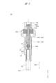
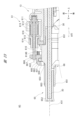
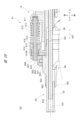
- FIG. 1 is a cross-sectional view showing a structure of a working machine according to an embodiment.
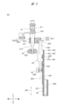
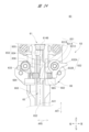
- 3A and 3B are diagrams illustrating a configuration of a movable portion according to the first embodiment.
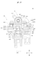
- 2 is a cross-sectional view of the movable part taken along line AA in FIG. 1.
- FIG. 2 is an external perspective view of a lock shaft.
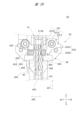
- 11A and 11B are diagrams illustrating a movable part when a pushing operation is performed.
- 11 is a cross-sectional view of the movable part when a pushing operation is performed.
- FIG. 13 is an external perspective view of the shaft guide, the lock shaft, and the lock lever when the push lever is in a fixed state (restricted state).
- FIG. 13 is an external view of the shaft guide, the lock shaft, and the lock lever when the push lever is in a fixed state (restricted state) as viewed from the front.
- FIG. 13 is an external perspective view of the shaft guide, the lock shaft, and the lock lever when the push lever is in the released state.
- FIG. 13 is an external view of the shaft guide, the lock shaft, and the lock lever when viewed from the front when the push lever is in the released state.
- FIG. 13A and 13B are diagrams illustrating the movable part when the push lever is in a released state.
- 11 is a cross-sectional view of the movable part when the push lever is in a released state.
- FIG. 11A and 11B are diagrams illustrating the movable part when the push lever is removed.
- FIG. 13A and 13B are diagrams illustrating a configuration of a movable portion according to a second embodiment.
- 13A and 13B are diagrams illustrating a configuration of a movable portion according to a second embodiment.
- 13A and 13B are diagrams illustrating a configuration of a movable portion according to a second embodiment.
- 13A and 13B are diagrams illustrating a configuration of a movable portion according to a second embodiment.
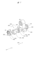
- FIG. 13 is an external perspective view of a movable portion according to a third embodiment;
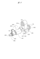
- FIG. 13 is an external perspective view of a movable portion according to a third embodiment;
- 19 is a cross-sectional view taken along line BB in FIG. 18.
- 19 is a cross-sectional view taken along line CC of FIG. 18.
- FIG. 19 is a cross-sectional view taken along line DD in FIG. 18.
- 11 is a cross-sectional view of the movable part when a pushing operation is performed.
- FIG. 11 is a cross-sectional view of the movable part when a pushing operation is performed.
- FIG. 11 is a cross-sectional view of a movable part when the push lever is attached or detached.
- FIG. 11 is a cross-sectional view of a movable part when the push lever is attached or detached.
- FIG. 11 is a cross-sectional view of the movable part when the push lever is removed.
- FIG. 11 is a cross-sectional view of the movable part when the adjustment mechanism is operated.
- FIG. 1 is a cross-sectional view of a work machine 10 according to a first embodiment.
- the work machine 10 is, for example, an electric nailer, and has a housing 11, a striking section 12, a nose section 13, a power supply section 14, an electric motor 15, a gear case 16, a pressure accumulator 18, a movable section 40, a control section 50, and a magazine 54.
- the housing 11 is an outer element of the working machine 10.
- the housing 11 has a cylinder case 20 that houses the impact part 12 described below, a handle 21, a motor case 22 that houses the electric motor 15 that functions as the drive part described below, and an attachment part 23. That is, the housing 11, the impact part 12 that is housed or fixed in the housing 11, the electric motor 15 that is the drive part, the nose part 13 described below, and the shaft guide 201 are the main body part.
- the handle 21 and the motor case 22 are connected to the cylinder case 20.
- the attachment part 23 is connected to the handle 21 and the motor case 22.
- a cylinder 28 is supported in the cylinder case 20.
- the cylinder 28 is made of metal.
- the cylinder 28 is fixed to the nose portion 13 described below, and is positioned relative to the cylinder case 20 via the nose portion 13 in the direction of an axis AX1 parallel to a first direction (vertical direction) AR1, and in the radial direction (direction perpendicular to the axis AX1).
- the axis AX1 is the direction in which the striking portion 12 described below extends.
- the handle 21 extends along the front-to-rear direction of the work machine 10. As shown in FIG. 1, a trigger 51 is provided below the handle 21. An operator can operate the trigger 51 while holding the handle 21. A trigger switch (not shown) is provided within the handle 21, which outputs an operation signal (ON signal) when an operating force is applied to the trigger 51. When the operating force on the trigger 51 is released, the trigger switch stops outputting the operation signal.
- a trigger 51 is provided below the handle 21.
- An operator can operate the trigger 51 while holding the handle 21.
- a trigger switch (not shown) is provided within the handle 21, which outputs an operation signal (ON signal) when an operating force is applied to the trigger 51. When the operating force on the trigger 51 is released, the trigger switch stops outputting the operation signal.
- the motor case 22 is a housing that houses the electric motor 15 and gear case 16 described below.
- the motor case 22 has a cylindrical shape that extends along the rotation axis AR2 of the electric motor 15.
- the rotation axis AR2 of the electric motor 15 extends in the first direction (vertical direction) AR1, i.e., in a direction that intersects with the axis AX1.
- the mounting section 23 is disposed at the rear end of the handle 21 and the motor case 22.
- the power supply section 14, which will be described later, is removably attached to the mounting section 23.
- a controller 501 of the control section 50 which will be described later, is also provided within the mounting section 23.
- the controller 501 is electrically connected to a trigger switch by wiring. When the operator operates the trigger 51, the controller 501 of the control section 50 outputs an electrical signal that instructs the electric motor 15, which will be described later, to start or stop driving in response to the operation.
- the striking section 12 is formed in a rod shape extending around the axis AX1, and strikes the stopper N.
- the striking section 12 has a piston 29 and a driver blade 30.
- the piston 29 is provided on the upper side of the axis AX1 direction (i.e., the up-down direction) and has a cylindrical shape with the axis AX1 as its axis.
- the piston 29 is provided on one side (lower side) of the first direction AR1 with respect to the pressure accumulator vessel 18, the details of which will be described later, and is always biased to one side (lower) of the first direction AR1 by the pressure of the pressure chamber 27 provided in the pressure accumulator vessel 18.
- the piston 29 is movable in the first direction AR1 along the axis AX1 inside the cylinder 28.
- a seal member is attached to the outer peripheral surface of the piston 29. The seal member contacts the inner peripheral surface of the cylinder 28 to form a seal surface.
- the driver blade 30 is made of, for example, metal.
- the driver blade 30 is connected to the piston 29 on the lower side of the piston 29 in the first direction AR1, and extends along the axis AX1. In other words, the driver blade 30 is connected to the piston 29 at its upper end. As described above, since the piston 29 can move in the first direction AR1, the driver blade 30 can also move in the first direction AR1.
- the driver blade 30 moves upward in the first direction AR1 by the driving force from the electric motor 15, which will be described later, via a transmission mechanism (not shown) that engages with the racks.
- a transmission mechanism (not shown) that engages with the racks.
- the movement of the driver blade 30 downward in the first direction AR1 (axis line AX1) in FIG. 1 is referred to as descending.
- the movement of the driver blade 30 upward in the first direction AR1 (axis line AX1) in FIG. 1 is referred to as ascending.
- the nose portion 13 is positioned relative to the cylinder case 20 in the direction of the axis AX1 and in the radial direction of the cylinder 28.
- the nose portion 13 has a bumper support portion 31, a bumper 35, and a blade guide 37.
- the bumper support portion 31 is cylindrical and has a guide hole 34.
- the guide hole 34 is positioned with the axis AX1 as its center.
- a bumper 35 is disposed within the bumper support portion 31.
- the bumper 35 is integrally formed from a synthetic rubber such as an elastomer.
- the bumper 35 is provided with a guide hole 36 centered on the axis AX1.
- the driver blade 30 described above is movable within the guide hole 36 in the first direction AR1 along the axis AX1.
- a blade guide 37 is provided on the bumper support portion 31.
- the blade guide 37 protrudes downward from the bumper support portion 31 in the first direction AR1.
- a concentric ejection path 38 is formed centered on the axis AX1.
- the driver blade 30 can move in the first direction AR1 along the axis AX1.
- a fastener N which is a fastener stored in a magazine 54 described later, is supplied to this ejection path 38.
- a shaft guide 201 that engages with the movable part 40 described below is fixed to the nose part 13.
- the shaft guide 201 is a member that constitutes the main body part.
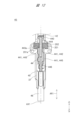
- Figure 2 is a diagram explaining the configuration of the movable part 40.
- Figure 3 is a cross-sectional view of the movable part 40 taken along line A-A in Figure 1. As shown in Figure 1, the movable part 40 is provided below the nose part 13.
- the movable part 40 has a shaft 41, an adjust arm 42, an adjuster 43, a lock shaft 44, a lock lever 45, and a push lever 46.
- the push lever 46 is detachably attached below the ejection passage 38 of the nose portion 13.
- the push lever 46 has an arm portion 461 extending along the first direction AR1 and a cylindrical head portion 462 centered on the axis line AX1.
- the arm portion 461 is formed with an attachment protrusion 460 that protrudes forward, i.e., toward the lock shaft 44 described later.
- the push lever 46 is fixed to the lock shaft 44 described later via this attachment protrusion 460.
- the head portion 462 is formed below the arm portion 461 and abuts against the opposing material W when the work machine 10 is in operation. In other words, the push lever 46 is an abutment portion that abuts against the opposing material W.
- the inside of the head portion 462 becomes the ejection passage through which the stopper N and the driver blade 30 pass.
- the push lever 46 is attached so as to be movable along the first direction AR1 in response to a pushing operation to press against the opposing material W. The movement of the push lever 46 will be described in more detail below.
- the shaft 41 is a rod-shaped member that extends along the first direction AR1.
- the shaft 41 functions as a base that is movable in the first direction AR1 as the push lever 46 moves along the first direction AR1 in response to a pushing operation, the details of which will be described later.
- the upper end of the shaft 41 is accommodated in a storage section 351 formed in the bumper 35.
- the shaft 41 is provided with an attachment arm 401 on which a magnet 402 (described later) is disposed.
- the shaft 41 below the attachment arm 401 is inserted through an insertion hole 420 formed in the adjust arm 42, an insertion hole 430 formed in the adjuster 43, and an insertion hole 202 (see FIG. 1) formed in the shaft guide 201.
- An elastic member 411 such as a spring is disposed between the upper part of the attachment arm 401 and the storage section 351. The elastic member 411 biases the shaft 41 downward.
- a step portion 412 is formed on the outer periphery of the shaft 41 below the mounting arm 401.
- the diameter of the shaft 41 differs between the upper and lower sides of the step portion 412. As shown in FIG. 2, the diameter is larger above the step portion 412 than below.
- This step portion 412 abuts against the upper surface of the adjuster 43 (described later), thereby restricting the downward movement of the shaft 41, which is biased downward by the elastic member 411.
- the adjusting arm 42 is a cylindrical member with an insertion hole 420 that passes through the adjusting arm 42 from the inside to the outside in the up-down direction (first direction AR1).
- the adjusting arm 42 is positioned lower than the mounting arm 401 provided on the shaft 41.
- the shaft 41 is inserted into the insertion hole 420.
- a female thread is formed on the inner surface of the insertion hole 420, which meshes with a male thread formed on the shaft 41, thereby threadably connecting the shaft 41 and the adjusting arm 42.
- the side of the adjust arm 42 is formed with an engagement portion 421 that engages with the lock shaft 44, which will be described later.
- the engagement portion 421 has protrusions 422, 423 that protrude in a direction (rearward) intersecting the first direction AR1.
- the engagement portion 421 is formed at a different position from the protrusions 422 and 423.
- a flange 440 formed on the lock shaft 44 which will be described later, is disposed in the space formed between the protrusions 422 and 423. This allows the adjust arm 42 and the lock shaft 44 to engage.
- the adjust arm 42 functions as a base that is movable in the first direction AR1 in accordance with the movement of the push lever 46 along the first direction AR1 in response to a pushing operation, which will be described in detail later.
- the adjuster 43 is provided below the shaft guide 201 (see FIG. 1).
- the adjuster 43 is an operating dial that is rotated by the operator to adjust the operability when the push lever 46 (described later) is pressed against the mating material W.
- the adjuster 43 is a cylindrical member in which an insertion hole 430 is formed that passes through the adjuster 43 in the vertical direction from the inside to the outside. The upper surface of the adjuster 43 abuts against the lower surface of the shaft guide 201.
- the shaft 41 is inserted into the insertion hole 430 as described above.
- Figure 4 is an external perspective view of the lock shaft 44.
- the lock shaft 44 is a support member that detachably supports the push lever 46 in the ejection path 38.
- the lock shaft 44 is a rod-shaped member that extends along the first direction AR1.
- the lock shaft 44 has a cylindrical main body portion 444 that extends along the first direction AR1, a flange 440, and a support portion 441.
- the flange 440 is formed on the upper end of the main body 444, and engages with the engagement portion 421 of the adjust arm 42 as described above.
- the lock shaft 44 is supported by the adjust arm 42 so as to be movable relative to the adjust arm 42, which is the base.
- the direction of relative movement of the lock shaft 44 with respect to the adjust arm 42 is different from the first direction AR1, which is the direction in which the lock shaft 44 extends.
- the direction of relative movement of the lock shaft 44 is a rotational direction centered on a rotation axis AR2 that is parallel to the first direction AR1.
- the support portion 441 is formed near the center of the main body portion 444 extending along the first direction AR1. Specifically, the support portion 441 has a first support protrusion 442, a second support protrusion 443, and a third support protrusion 445.
- the first support protrusion 442 is formed along the outer periphery of the main body portion 444 and is a flange with a larger diameter than the main body portion 444.
- the second support protrusion 443 is formed on the upper surface of the first support protrusion 442.
- the second support protrusion 443 has a thickness that is a portion of the outer periphery of the main body portion 444 and extends upward along the first direction AR1.
- the third support protrusion 445 is formed below and spaced apart from the first support protrusion 442.
- the third support protrusion 445 is formed with a larger diameter than the main body 444 in a portion of the outer periphery of the main body 444. Therefore, in a portion of the outer periphery of the main body 444, a space S is formed in the first direction AR1 between the lower surface of the first support protrusion 442 and the upper surface of the third support protrusion 445. In addition, in the remaining portion of the outer periphery of the main body 444, the above-mentioned space S is not formed in the first direction AR1.
- a state is switched between one in which the mounting protrusion 460 of the push lever 46 is disposed in the space S and one in which the mounting protrusion 460 is not disposed in the space S.
- the push lever 46 is fixed to the shaft 41 and the adjust arm 42 (fixed state) via the lock shaft 44.
- the push lever 46 is in a restricted state in which removal from the shaft 41 (base) is restricted.
- the push lever 46 is in a released state (released state) from the fixation to the shaft 41 and the adjust arm 42 (base). In the released state, the push lever 46 is not restricted from removing from the shaft 41.
- the lock shaft 44 functions as a restricting part that can switch between a fixed state (restricted state) in which the push lever 46 is fixed to the shaft 41 and the adjust arm 42, which are the base parts, and a releasable state in which the fixation is released.
- a fixed state restricted state
- the lock shaft 44 fixes the push lever 46 to the shaft 41 and the adjust arm 42, which are the base parts, when in the restricted state.
- the lock shaft 44 has a rod-shaped attachment portion 446 extending along the first direction AR1 below the support portion 441.
- the attachment portion 446 is inserted into an insertion hole 450 of the lock lever 45 described below.
- the outer peripheral surface of the attachment portion 446 is formed in a flat shape, part of which extends along the first direction AR1. In other words, the cross section of the attachment portion 446 in a plane perpendicular to the first direction AR1 is non-circular with corners.
- the lock lever 45 is provided below the lock shaft 44.
- the lock lever 45 has an insertion hole 450 that penetrates the lock lever 45 from inside to outside along the first direction AR1.
- the insertion hole 450 has a non-circular inner periphery with corners that is formed in a shape corresponding to the cross-sectional shape of the mounting portion 446 of the lock shaft 44 (see Figure 7 described later).
- the mounting portion 446 of the lock shaft 44 described above is inserted into this insertion hole 450. As a result, the lock shaft 44 is held so as to be movable relative to the lock lever 45 along the first direction AR1.
- the lock lever 45 is a member that is operated by an operator when rotating the lock shaft 44 around the rotation axis AR2. That is, the lock lever 45 is rotated by the operator along the rotation direction AR3 or AR4 when setting the push lever 46 to either the fixed state (restricted state) or the released state.
- a corner formed on the outer circumferential surface of the mounting portion 446 of the lock shaft 44 comes into contact with a corner formed on the inner wall surface of the insertion hole 450, causing the lock shaft 44 to rotate around the rotation axis AR2.
- the power supply unit 14 is detachably attached to the mounting unit 23, and is a DC power supply that supplies power to the electric motor 15 and the like.
- the power supply unit 14 has a housing case and a number of battery cells housed within the housing case.
- the battery cells are secondary batteries that can be charged and discharged, and any of the following can be used: lithium ion batteries, nickel metal hydride batteries, lithium ion polymer batteries, and nickel cadmium batteries.
- the electric motor 15 is a drive unit that receives power from the power supply unit 14 to rotate and drive the impact unit 12.
- the electric motor 15 is disposed inside the motor case 22.
- the electric motor 15 is, for example, a brushless motor having a rotor and a stator.
- the gear case 16 is provided in front of the electric motor 15 inside the motor case 22.
- the gear case 16 is cylindrical and does not rotate relative to the nose portion 13.
- a reduction mechanism having an input element, an output element, and multiple sets of planetary gear mechanisms is provided inside the gear case 16.
- the input element of the reduction mechanism is connected to the rotating shaft of the electric motor 15, and the input element is rotatably supported by bearings.
- the rotational force of the output element of the reduction mechanism inside the gear case 16 is converted by a transmission mechanism (not shown) into a moving force in a first direction AR1 along the axis AX1 and transmitted to the driver blade 30.
- the pressure accumulator vessel 18 has a cap 24.
- a head cover 26 is attached to the upper side of the cylinder case 20 in the first direction AR1, and the pressure accumulator vessel 18 is disposed within the cylinder case 20 and the head cover 26.
- a pressure chamber 27 is provided within the pressure accumulator vessel 18.
- the pressure chamber 27 is filled with gas. Any compressible gas may be used as the gas. In addition to air, an inert gas such as nitrogen gas or a rare gas may be used as the gas.
- the pressure of the pressure chamber 27 provided in the pressure accumulator vessel 18 constantly biases the striking portion 12 to one side (downward) in the first direction AR1. Note that the following description will be given assuming that the pressure chamber 27 is filled with air.
- the magazine 54 is disposed on one side (below) of the first direction (up-down direction) AR1 with respect to the handle 21 and the motor case 22 (i.e., the electric motor 15).
- the magazine 54 contains a plurality of connected fasteners N.
- the multiple fasteners N are connected to each other by connecting elements such as adhesive, wire, etc.
- the fasteners N contained in the magazine 54 are supplied into the ejection path 38 by a supply mechanism (not shown). That is, of the fasteners N contained in the magazine 54, the fastener N located at the front of the connecting elements is supplied so as to be located below the driver blade 30.
- the control unit 50 has a controller 501 and a sensor 502 (see Figure 2).
- the controller 501 is provided inside the mounting unit 23.
- the controller 501 is a microcomputer having an input port, an output port, an arithmetic processing unit, and a memory unit. As described above, the controller 501 is electrically connected to the trigger switch by wiring. When the operator operates the trigger 51, the trigger switch outputs an electrical signal to the controller 501.
- the sensor 502 is, for example, a magnetic sensor, and detects the position of the shaft 41 and the adjust arm 42, which are the base parts, that change when the push lever 46 is pushed. Specifically, the sensor 502 is positioned in the first direction AR1 above the mounting arm 401 of the shaft 41 when the push lever 46 is not pressed against the mating material W. The sensor 502 outputs an ON signal to the controller 501 when the magnitude of the magnetic field (magnetic field) generated by the magnet 402 attached to the mounting arm 401 of the shaft 41 exceeds a preset value.
- the controller 501 outputs an electrical signal instructing the electric motor 15 to start or stop driving in response to the operator's operation of the trigger 51 and the pushing operation of the push lever 46.
- the sensor 502 described above may be a contact switch having a contact piece.
- ⁇ Operation of the work machine 10 An example of the operation of the work machine 10 when the work machine 10 is used as a nail driver to drive a nail, which is a fastener N, into a mating material W will be described.
- the control unit 50 controls the electric motor 15 so that it does not supply power when at least one of the trigger switch or the sensor 502 is off.
- the push lever 46 is separated from the opposing material W.
- the push lever 46 is fixed to the lock shaft 44, which is engaged with the adjust arm 42.
- the step portion 412 of the shaft 41 abuts against the upper surface of the adjuster 43, the downward movement of the shaft 41, which is biased downward by the elastic member 411, is restricted. Therefore, the push lever 46 is stopped in the initial position.
- the shaft 41 and the adjust arm 42 which form the base of the movable part 40, are located in the first position where the sensor 502 is turned off.
- the operator applies operating force to the trigger 51 and performs a pushing operation to press the push lever 46 against the target material W.
- Figure 5 is a diagram explaining the movable part 40 when a push operation is performed.
- Figure 6 is a cross-sectional view of the movable part 40 similar to Figure 3 when a push operation is performed.
- the push lever 46 moves upward along the first direction AR1 against the biasing force of the elastic member 411 acting through the adjust arm 42 and the lock shaft 44.
- the lock shaft 44 to which the push lever 46 is fixed, the adjust arm 42 engaged with the lock shaft 44, and the shaft 41 screw-connected to the adjust arm 42 move upward against the biasing force of the elastic member 411.
- the movable part 40 can move upward relative to the main body part including the shaft guide 201 by abutting against the opposing material W.
- the push lever 46 moves upward by the push operation and reaches a position (second position) where the sensor 502 is turned on.
- the shaft 41 and the adjust arm 42 that form the base of the movable part 40 are located in the second position where the sensor 502 is turned on.
- the controller 501 of the control unit 50 controls the power supply unit 14 to supply power to the electric motor 15.
- the drive shaft is rotated by the electric motor 15 that has received the power supply, the rotational force is transmitted to the driver blade 30 of the striking unit 12 via a transmission mechanism (not shown).
- the controller 501 of the control unit 50 controls the drive of the electric motor 15, which is the drive unit, according to the position of the movable unit 40.
- the drive force transmitted from the electric motor 15 causes the driver blade 30 to rise against the pressure in the pressure chamber 27.
- the driver blade 30 When the driver blade 30 reaches the top dead center and the rotational force is no longer transmitted, the driver blade 30 descends due to the pressure in the pressure chamber 27 and is guided to the injection path 38, moving to one side (the downward side) in the first direction AR1 (i.e., the direction of the axis AX1). The driver blade 30 then strikes the fastener N supplied to the injection path 38. That is, the driver blade 30 of the striking section 12 moves in the axis AX1 direction along the axis AX1, striking the fastener N on the lower side in the axis AX1 direction. As a result, the fastener N is struck by the driver blade 30 and driven into the mating material W.
- Figure 7 is an external perspective view of the shaft guide 201, the lock shaft 44, and the lock lever 45 when the push lever 46 is in a fixed state (restricted state).
- Figure 8 is an external view of the shaft guide 201, the lock shaft 44, and the lock lever 45 when viewed from the front when the push lever 46 is in a fixed state (restricted state).
- the operator rotates the lock lever 45 along the rotation operation direction AR3 in FIG. 7.
- the lock shaft 44 inserted into the insertion hole 450 of the lock lever 45 also rotates along the rotation operation direction AR3.
- Figure 9 is an external perspective view of the shaft guide 201, lock shaft 44, and lock lever 45 after a rotation operation has been performed.
- Figure 10 is an external view of the shaft guide 201, lock shaft 44, and lock lever 45 as viewed from the front after a rotation operation has been performed.
- Figures 11 to 13 are diagrams explaining the movable part 40 after a rotation operation has been performed.
- the rotation of the lock shaft 44 causes the third support protrusion 445 formed on the lock shaft 44 and the mounting protrusion 460 of the push lever 46 to no longer overlap in the first direction AR1.
- the push lever 46 transitions to a release state in which the mounting protrusion 460 is not positioned in the space S formed between the first support protrusion 442 and the third support protrusion 445 of the lock shaft 44.
- the adjust arm 42 engaged with the lock shaft 44 and the shaft 41 screw-connected to the adjust arm 42 do not move upward along the first direction AR1. In other words, they do not move to the second position where the sensor 502 turns on.
- the push lever 46 when the push lever 46 is in the released state, the movement of the base shaft 41 and the adjust arm 42 from the first position to the second position is restricted.
- the shaft guide 201 abuts against the lock shaft 44, and functions as a stopper portion that restricts the movement of the base shaft 41 and the adjust arm 42 from the first position to the second position.
- the sensor 502 Since the sensor 502 does not output an ON signal, power is not supplied from the power supply unit 14 to the electric motor 15 under the control of the controller 501 of the control unit 50. In other words, since the electric motor 15 is not driven, the striking unit 12 does not strike the stopper N. In other words, when the push lever 46 is in the released state, striking the stopper N is prohibited.
- the upper surface 443a of the second support protrusion 443 is in contact with the lower surface 201a of the shaft guide 201. Therefore, even if excessive upward force is applied when attaching the push lever 46, the lock shaft 44 is restricted from moving upward. Therefore, when attaching the push lever 46, the lock shaft 44, the adjust arm 42, and the shaft 41 are prevented from moving upward, and the sensor 502 is prevented from turning on.
- the lock shaft 44 to which the lock lever 45 is fixed also rotates in the rotation operation direction AR4.
- the third support protrusion 445 formed on the lock shaft 44 and the mounting protrusion 460 of the push lever 46 overlap in the first direction AR1. That is, the push lever 46 transitions to a fixed state (restricted state) in which the mounting protrusion 460 is disposed in the space S formed between the first support protrusion 442 and the third support protrusion 445 of the lock shaft 44, as shown in FIG. 2.
- the lock shaft 44 moves relative to the adjust arm 42, which is its base, along the rotational operation directions AR3 and AR4, which are different from the first direction AR1.
- This causes the push lever 46 to switch between a fixed state (restricted state) and a released state.
- the working machine 10 has a movable part 40 that can move relative to the housing 11 by abutting against the opposing material W.
- the movable part 40 includes a shaft 41 and an adjust arm 42 that are base parts that can move relative to the housing 11 between a first position and a second position, and a push lever 46 that abuts against the opposing material W.
- the push lever 46 can be switched between a restricted state in which the shaft 41 and the adjust arm 42 are restricted from being separated from each other, and a released state in which the restriction is released.
- the striking part 12 can strike the stopper N when the push lever 46 is in the restricted state, and is prohibited from striking the stopper N when the push lever 46 is in the released state.
- the electric motor 15 is driven when the push lever 46 is in the released state, and the striking part 12 is prevented from operating, so that the worker does not need to be careful not to turn on the sensor 502 when replacing the push lever 46.
- the convenience of using the working machine 10 is improved.
- the lock shaft 44 can fix and release the push lever 46 to and from the shaft 41 and the adjust arm 42. This allows the push lever 46 to be switched between a fixed state (restricted state) and a released state with a simple configuration, improving convenience for the operator when using the work machine 10.
- a shaft guide 201 is fixed to the nose portion 13.
- the shaft guide 201 comes into contact with the lock shaft 44 to restrict the movement of the shaft 41 and the adjust arm 42 from the first position to the second position.
- the sensor 502 does not turn on, so the electric motor 15 is driven and the impact portion 12 is prevented from operating. As a result, the convenience of using the work machine 10 is improved.
- ⁇ Second embodiment> A working machine of the second embodiment will be described. Below, the same reference numerals will be given to configurations similar to those of the working machine 10 of the first embodiment, and differences from the first embodiment will be mainly described. Points that are not specifically described are similar to those of the first embodiment.
- the second embodiment differs from the working machine 10 of the first embodiment in that the working machine is equipped with a sensor that detects whether the push lever is in a fixed state (restricted state) or a released state. This will be described in detail below.
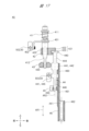
- Figure 14 is a diagram illustrating the movable part 40 of the second embodiment when the push lever 46 is in a fixed state (restricted state).
- Figure 15 is a diagram illustrating the movable part 40 of the second embodiment when the push lever 46 is pushed when in a fixed state (restricted state).
- Figure 16 is a diagram illustrating the movable part 40 of the second embodiment when the push lever 46 is in a released state.
- Figure 17 is a diagram illustrating the movable part 40 of the second embodiment when the push lever 46 is pushed when in a released state.
- the control unit 50 of the work machine 10 of the second embodiment has a sensor 503 in addition to the controller 501 and sensor 502 of the first embodiment.
- the sensor 503 detects the state of the push lever 46, i.e., whether the push lever 46 is in a locked state (restricted state) or a released state. Specifically, the sensor 503 outputs an ON signal to the controller 501 when the magnitude of the magnetic field (magnetism) generated by the magnet 504 provided on the lock shaft 44 exceeds a preset value.
- the magnet 504 is disposed at a position on the lock shaft 44 opposite the sensor 503.
- the sensor 503 detects that the push lever 46 is in a fixed state (restricted state) and outputs an ON signal to the controller 501.
- the controller 501 of the control unit 50 causes the power supply unit 14 to supply power to the electric motor 15. That is, when the sensor 502 detects that the base shaft 41 and the adjustment arm 42 are in the second position and the sensor 503 detects that the push lever 46 is in a fixed state (restricted state), the controller 501 of the control unit 50 allows the electric motor 15 to operate so that the striking unit 12 strikes the stopper N.
- the controller 501 does not supply power from the power supply unit 14 to the electric motor 15. In other words, when the push lever 46 is in the released state, the controller 501 of the control unit 50 prohibits the electric motor 15 from being driven so that the striking unit 12 strikes the stopper N.
- the second embodiment also provides the following effect in addition to at least one of the effects (1) to (3) and (5) provided by the above-mentioned embodiment.
- the controller 501 of the control unit 50 allows the electric motor 15 to be driven so that the striking unit 12 strikes the stopper N.
- the sensor 503 does not turn on, so the electric motor 15 is prevented from being driven and the striking unit 12 from operating.
- the convenience of using the working machine 10 is improved.
- this since there is no need for a member to restrict the movement of the shaft 41 and the adjust arm 42 when the push lever 46 is in the released state, this contributes to making the working machine 10 smaller and lighter.
- ⁇ Third embodiment> A work machine of the third embodiment will be described. Below, the same reference numerals are given to configurations similar to those of the work machine 10 of the first embodiment, and differences from the first embodiment will be mainly described. Points that are not specifically described are the same as those of the first embodiment.
- the third embodiment has a moving part that is different from the moving part 40 of the first embodiment.
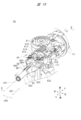
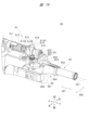
- Figures 18 and 19 are external perspective views of the movable part 60 of the work machine 10 of the third embodiment.
- Figure 20 is a cross-sectional view taken along line B-B in Figure 18.
- Figure 21 is a cross-sectional view taken along line C-C in Figure 18.
- Figure 22 is a cross-sectional view taken along line D-D in Figure 18.
- the movable part 60 of the third embodiment is also provided below the nose part 13, similar to the movable part 40 of the first embodiment. Because the movable part 60 is different from the movable part 40 of the first embodiment, the blade guide 66 of the nose part 13 is different from the blade guide 37 of the first embodiment. In addition, in the third embodiment, a regulating mechanism 63 is provided for switching the state of the movable part 60.
- the blade guide 66 is fixed below the nose portion 13 and protrudes downward in the first direction AR1. As explained in the first embodiment, the housing 11, striking portion 12, electric motor 15, and nose portion 13 form the main body. Therefore, the blade guide 66 fixed to the nose portion 13 is also the main body.
- An injection path 38 is formed inside the blade guide 66, centered on the axis AX1.
- the blade guide 66 has a first guide member 661 and a second guide member 662.
- the first guide member 661 is a cylindrical member centered on the axis AX1.
- a guide groove 663 is formed on the front side of the first guide member 661, extending along the first direction AR1.
- the second guide member 662 is attached to the front side of the first guide member 661.
- Guide grooves 664, 665 are formed in the wall surface on the side (i.e., the rear side) of the second guide member 662 facing the first guide member 661.
- the guide groove 664 is formed at a position facing the guide groove 663 formed in the first guide member 661, and extends along the first direction AR1.
- the guide groove 665 extends along a second direction AR5 that intersects with the first direction AR1 and the front-to-rear direction.
- the second direction AR5 may be referred to as the left-to-right direction.
- the second guide member 662 is also formed with a protruding portion 666 that protrudes forward.
- the protruding portion 666 is formed with a through hole 667 that passes through the protruding portion 666 in the up-down direction.
- the movable part 60 includes an adjustment mechanism 61 and a push lever 65.
- ⁇ Push lever 65> The push lever 65 is removably attached to the ejection path 38 inside the blade guide 66.
- the push lever 65 can be removed by pulling it downward, as will be described in detail later.
- the push lever 65 has an arm portion 651 extending along the first direction AR1 and a cylindrical head portion 652 centered on the axis line AX1.
- a protrusion 653 is formed on the front side of the arm portion 651, protruding toward the second guide member 662 of the blade guide 66 (i.e., the front side).
- the protrusion 653 protrudes toward the second guide member 662 via the guide groove 663.
- the protrusion 653 is formed by a first protrusion 654, a second protrusion 655, and a third protrusion 656.
- the first protrusion 654 extends along the first direction AR1.
- the second protrusion 655 protrudes from the first protrusion 654 above the first protrusion 654 toward one side in the second direction AR5 (left-right direction).
- the third protrusion 656 protrudes from the first protrusion 654 below the first protrusion 654 toward the other side in the second direction AR5 (left-right direction).
- the distance (separation distance) in the first direction AR1 between the upper end surface of the third protrusion 656 and the lower end surface of the second protrusion 655 is equal or approximately equal to the width (length in the first direction AR1) of the guide groove 665 formed in the second guide member 662.
- one side in the second direction AR5 may be referred to as the right side
- the other side in the second direction AR5 may be referred to as the left side.
- the head portion 652 is formed below the arm portion 651 and contacts the opposing material W when the working machine 10 is operating. That is, even in the third embodiment, the push lever 65 functions as the contact portion.
- the push lever 65 is attached so as to be movable along the first direction AR1 in response to a pressing operation against the opposing material W.
- the adjustment mechanism 61 is provided below the nose portion 13, forward of the push lever 65 and the blade guide 66.
- the adjustment mechanism 61 has an adjuster shaft 610, an operating portion 611, a sleeve 612, a first adjuster piece 613, a second adjuster piece 614, an elastic member 615, and a moving portion 616.
- the adjuster shaft 610 is a rod-shaped member that extends along the first direction AR1 and is centered on an axis AX2 along the first direction AR1.
- the adjuster shaft 610 has an upper end fixed to the nose portion 13 so as to be rotatable around the axis AX2.
- the lower end of the adjuster shaft 610 is inserted into a through hole 667 formed in the protrusion 666 of the second guide member 662.
- the operating unit 611 is attached to the upper side of the adjuster shaft 610 and is a member operated by an operator.
- a through hole 611A is formed in the operating unit 611 and is centered on the axis line AX2.
- the operating unit 611 is attached to the adjuster shaft 610 by inserting the adjuster shaft 610 into the through hole 611A.
- the adjuster shaft 610 rotates around the axis line AX2 together with the operating unit 611.
- the sleeve 612 is provided below the operating part 611 and is cylindrical with its center on the axis AX2.
- the sleeve 612 extends along the first direction AR1.
- the adjuster shaft 610 is inserted inside the sleeve 612.
- a flange is formed at the upper end of the sleeve 612. The sleeve 612 abuts against the operating part 611 at this flange.
- the moving part 616 is attached to the front surface of the second guide member 662 so as to be movable along the first direction AR1.
- the moving part 616 protrudes forward and has a moving surface 616A that intersects with the first direction AR1.
- a through hole 616B centered on the axis AX2 is formed in the moving surface 616A.
- the adjuster shaft 610 is inserted into this through hole 616B.
- the moving surface 616A is located below the lower end of the sleeve 612.
- the first adjuster piece 613 is cylindrical and centered on the axis AX2.
- the adjuster shaft 610 is inserted inside the first adjuster piece 613.
- the upper end of the first adjuster piece 613 abuts against the lower surface of the moving surface 616A of the moving part 616.
- the first adjuster piece 613 rotates around the axis AX2 together with the adjuster shaft 610.
- an inclined step portion 613B inclined with respect to the first direction AR1 is formed on the outer peripheral wall surface 613A of the first adjuster piece 613.
- the second adjuster piece 614 is cylindrical and centered on the axis AX2.
- the second adjuster piece 614 is provided outside the outer peripheral wall surface 613A of the first adjuster piece 613, overlapping with a portion of the outer peripheral wall surface 613A.
- An inclined step portion 614A inclined with respect to the first direction AR1 is formed on the outer peripheral wall surface of the second adjuster piece 614.
- the inclined step portions 613B, 614A abut against each other. Therefore, when the first adjuster piece 613 rotates in response to the operation of the operating portion 611, the inclined step portion 614A slides against the inclined step portion 613B, causing the second adjuster piece 614 to move up and down along the first direction AR1.
- a wall protrusion 614B that protrudes toward the push lever 65 is formed on the rear side of the outer peripheral wall of the second adjuster piece 614.
- the elastic member 615 is, for example, a coil spring, and the adjuster shaft 610 is inserted inside.
- the elastic member 615 is disposed between the sleeve 612 and the moving surface 616A.
- the upper end of the elastic member 615 abuts against the lower end surface of the flange formed at the upper end of the sleeve 612, and the lower end of the elastic member 615 abuts against the upper end surface of the moving surface 616A.
- the moving surface 616A is biased downward along the first direction AR1.
- the first adjuster piece 613 abuts against the moving surface 616A
- the second adjuster piece 614 abuts against the first adjuster piece 613 at the inclined step portions 613B and 614A. Therefore, the first adjuster piece 613 and the second adjuster piece 614 are also biased downward along the first direction AR1.
- the restriction mechanism 63 is provided on the blade guide 66.
- the restriction mechanism 63 has an eject slider 631, an eject lever 632, and a biasing member 633.
- the eject slider 631 is accommodated in the above-mentioned guide groove 665 so as to be movable in the second direction AR5 (left-right direction).
- a recess 631A extending along the first direction AR1 is formed on the rear surface (first guide member 661 side) of the eject slider 631.
- a first slider protrusion 631B and a second slider protrusion 631C that protrude rearward are formed on the rear surface of the eject slider 631.
- the first slider protrusion 631B is formed on the right side of the recess 631A in the second direction AR5.
- the second slider protrusion 631C is formed on the left side of the recess 631A in the second direction AR5.
- the width (length) of the eject slider 631 is equal or approximately equal to the width (length) of the guide groove 665. Therefore, the movement of the eject slider 631 along the first direction AR1 is restricted by contact with the upper or lower side wall surface of the guide groove 665 (i.e., the second guide member 662, which is the main body).
- the eject lever 632 is provided on the second guide member 662.
- the eject lever 632 is attached so as to be rotatable around a rotation axis AX3 along the front-rear direction.
- the eject lever 632 is formed with an operating protrusion 632A and a contact protrusion 632B.
- the operating protrusion 632A is operated by the operator when attaching or detaching the push lever 65.
- the abutting protrusion 632B is formed at a predetermined angle with the operating protrusion 632A around the rotation axis AX3.
- the right side wall surface of the abutting protrusion 632B abuts against the left side wall surface of the second slider protrusion 631C of the eject slider 631.
- the biasing member 633 is, for example, a torsion spring, and is wound around a shaft portion 633A provided on the second guide member 662. One end of the biasing member 633 abuts against the right side wall surface of the first slider protrusion portion 631B of the eject slider 631. As a result, the biasing member 633 biases the eject slider 631 to the left in the second direction AR5.
- the first slider protrusion 631B is located below the second protrusion 655 that constitutes the protrusion 653 of the push lever 65, and abuts against the right side wall surface of the first protrusion 654.
- the push lever 65 can move upward relative to the eject slider 631, the blade guide 66, and the adjustment mechanism 61 provided on the blade guide 66.
- the upper end surface of the first slider protrusion 631B abuts against the lower end surface of the second protrusion 655. Therefore, the push lever 65 is restricted from moving downward relative to the eject slider 631, the blade guide 66, and the adjustment mechanism 61, and is stopped in the initial position. In other words, the push lever 65, which is the abutting part, is in a restricted state in which it is restricted from coming off the blade guide 66 and the adjustment mechanism 61.
- the operator applies an operating force to the trigger 51 and performs a pushing operation to press the push lever 65 against the target material W.
- the push lever 65 moves upward relative to the blade guide 66.
- Figures 23 and 24 are cross-sectional views of the movable part 60 when a pushing operation is performed. Note that Figure 23 is a cross-sectional view in the same direction as Figure 20, and Figure 24 is a cross-sectional view in the same direction as Figure 22.
- the push lever 65 can move upward relative to the blade guide 66. As a result, when a pushing operation is performed, the push lever 65 moves upward along the first direction AR1.
- the working machine 10 thereafter performs the same operation as described in the first embodiment, driving the fastener N into the mating material W. That is, even in the third embodiment, the striking unit 12 can strike the fastener N when the push lever 65 is in the restricted state.
- the push lever 65 is in the initial position, and the first adjuster piece 613, the second adjuster piece 614, and the moving unit 616 are in the first position.
- the adjustment mechanism 61 including the first adjuster piece 613, the second adjuster piece 614, and the moving unit 616 is a base that can move between the first position and the second position relative to the blade guide 66, which is the main body.
- the operator When removing the push lever 65, the operator first operates the eject lever 632. Specifically, the operator hooks a finger or the like on the operating protrusion 632A and rotates the eject lever 632 in the clockwise direction in FIG. 22 around the rotation axis AX3.
- a force to the right along the second direction AR5 acts on the eject slider 631 via the second slider protrusion 631C, which abuts against the abutment protrusion 632B.
- the eject slider 631 moves to the right in the second direction AR5 along the guide groove 665 of the second guide member 662, against the biasing force of the biasing member 633.
- Figures 25, 26, and 27 are cross-sectional views of the movable part 60 and the regulating mechanism 63 when the eject slider 631 has moved to the right along the second direction AR5. Note that Figures 25 and 26 show cross-sections of the movable part 60 and the regulating mechanism 63 in the same positions as in Figures 21 and 22, respectively. Figure 27 is a cross-sectional view of the movable part 60 and the regulating mechanism 63 when the push lever 65 is pulled downward in the state shown in Figure 26.
- the first slider protrusion 631B of the eject slider 631 is spaced apart from the guide grooves 663 and 664. This allows the push lever 65 to move downward relative to the blade guide 66. In other words, the push lever 65, which is the contact part, is in a released state in which it is not restricted from coming off the blade guide 66 and the adjustment mechanism 61, which is the base.
- the push lever 65 is configured to be switchable between the restricted state and the released state described above.
- the restricting mechanism 63 (more specifically, the eject slider 631) switches the push lever 65 between the restricted state and the released state.
- the eject slider 631 functions as a restricting part that allows the push lever 65, which is the contact part, to be prevented from being removed from the adjustment mechanism 61, which is the base of the push lever 65.
- the restricting state and the released state are switched by the eject slider 631 moving in a second direction AR5 that intersects with the first direction AR1, which is the relative movement direction of the adjustment mechanism 61.
- the operator can remove the push lever 65 by pulling the push lever 65, which has been released as described above, downward along the first direction AR1. That is, even in the third embodiment, the attachment/detachment direction of the push lever 65 and the movement direction of the movable part 60 are parallel or approximately parallel.
- the second adjuster piece 614 does not receive an upward force from the push lever 65 via the wall surface protrusion 614B.
- the first adjuster piece 613, the second adjuster piece, and the moving part 616 are positioned in the first position by the biasing force of the elastic member 615.
- the adjustment mechanism 61 which is the base, is restricted from moving from the first position to the second position when the push lever 65 is in the released state.
- the push lever 65 Since the first adjuster piece 613, the second adjuster piece, and the moving part 616 do not move to the second position, when the push lever 65 is in the released state, power is not supplied from the power supply unit 14 to the electric motor 15 under the control of the controller 501 of the control part 50. In other words, as in the case of the first embodiment, the striking part 12 does not strike the stopper N. In other words, when the push lever 65 is in the released state, striking the stopper N is prohibited.
- the width (length) of the eject slider 631 is equal or approximately equal to the width (length) of the guide groove 665. That is, the eject slider 631 is restricted from moving along the first direction AR1 by contacting the second guide member 662, which is the main body. Therefore, even if an upward force acts on the eject slider 631 in the released state, the upward movement (relative movement direction) of the push lever 65 and the adjustment mechanism 61, which is the base, is restricted. For example, even if an impact is applied to the eject slider 631 when the stopper N is stuck in the ejection path 38, the second guide member 662 can receive the impact. As a result, the upward movement of the adjustment mechanism 61 is restricted, and the unintended supply of power to the electric motor 15 by the control unit 50 is restricted.
- the eject lever 632 is operated by the operator in the same manner as when removing the push lever 65. That is, the first slider protrusion 631B of the eject slider 631 is separated from the guide grooves 663 and 664, and a part of the second slider protrusion 631C is positioned within the guide grooves 663 and 664.
- the push lever 65 is inserted upward along the first direction AR1. Then, the upper end surface of the third protrusion 656 of the push lever 65 comes into contact with the lower end surface of the second slider protrusion 631C. That is, the state shown in FIG. 26 is reached. This restricts the push lever 65 from moving further upward. In other words, the push lever 65 is restricted from moving excessively upward along the first direction AR1 relative to the blade guide 66. Therefore, even if excessive upward force is applied to the push lever 65 during insertion, the adjustment mechanism 61 does not move upward, so unintentional supply of power to the electric motor 15 by the control unit 50 is suppressed.
- the eject slider 631 moves to the left along the second direction AR5 due to the biasing force of the biasing member 633. Then, as shown in FIG. 22, the first slider protrusion 631B abuts against the second guide member 662 below the second protrusion 655 of the push lever 65 (see FIG. 21). This restricts the eject slider 631 from moving further to the left.
- the second slider protrusion 631C of the eject slider 631 moves away from the guide grooves 663 and 664.
- the upward movement of the push lever 65 is not restricted, but the downward movement is restricted.
- the push lever 65 is in a restricted state in which it is restricted from coming off the blade guide 66 and the adjustment mechanism 61.
- Figure 28 is a cross-sectional view of the movable part 60 after the operating part 611 of the adjustment mechanism 61 is operated from the state shown in Figure 20.
- Figure 28 shows the state in which the second adjuster piece 614 has moved downward along the first direction AR1.
- the distance in the first direction AR1 between the upper end surface of the first adjuster piece 613 and the lower end surface of the second adjuster piece 614 is longer than that in the state shown in FIG. 20. That is, the relative positions of the push lever 65 and the second adjuster piece 614 and the blade guide 66 when the push lever 65, the first adjuster peel 613, and the second adjuster piece 614 are in the second position are different between the state shown in FIG. 20 and the state shown in FIG. 28.
- the distance between the lower end of the push lever 65 (the counter material W abutting the push lever 65) and the lower end of the blade guide 66 when the push lever 65 is in the second position is longer than that in the state shown in FIG. 20. That is, by changing the distance between the counter material W and the blade guide 66 according to the material of the counter material W, etc., it is possible to adjust the driving depth of the fastener N driven into the counter material W.
- the eject slider 631 of the regulating mechanism 63 can regulate and release the removal of the push lever 65 from the adjustment mechanism 61. Specifically, the eject slider 631 of the regulating mechanism 63 switches the push lever 65 between a regulated state and a released state by moving in a second direction AR5 that intersects with the relative movement direction (first direction AR1) of the adjustment mechanism 61. This simplifies the structure of the regulating mechanism 63, which has the effect of reducing the size and improving the durability of the regulating mechanism 63, thereby improving convenience. In addition, the push lever 65 can be switched between a regulated state and a released state with a simple configuration, which improves convenience when the operator uses the work machine 10.
- step portion 420... insertion hole, 421... engagement portion, 422, 423... protrusion, 430... insertion hole, 440... flange, 441... support portion, 442... first support protrusion, 443... second support protrusion, 444...
- main body 445 ...third support protrusion, 446...mounting portion, 450...insertion hole, 460...mounting protrusion, 461...arm portion, 462...head portion, 501...controller, 502, 503...sensor, 610...adjuster shaft, 611...operation portion, 612...sleeve, 613...first adjuster piece, 613B, 614A...inclined step portion, 614...second adjuster piece, 614B...wall surface protrusion, 615...elastic member, 616...moving portion, 631...eject slider, 631B...first slider protrusion, 631C...second slider protrusion, 632...eject lever, 632A...operation protrusion, 632B...contact protrusion, 633...biasing member, 653...protrusion, 654...first protrusion, 655...second protrusion, 656...third protrusion, 661...first guide member, 662...second guide member, 663, 664, 665...guide groove,
Landscapes
- Engineering & Computer Science (AREA)
- Mechanical Engineering (AREA)
- Physics & Mathematics (AREA)
- Fluid Mechanics (AREA)
- Portable Nailing Machines And Staplers (AREA)
Abstract
利便性を向上させた作業機を提供する。作業機10は、止具を打撃する打撃部12を駆動する電動モータ15と、打撃部12及び電動モータ15を有するハウジング11と、相手材Wに当接することで、ハウジング11に対して相対移動可能な可動部40と、可動部40の位置に応じて電動モータ15の駆動を制御する制御部50と、を備える。可動部40は、第1位置と第2位置との間でハウジング11に対して相対移動可能なシャフト41及びアジャストアーム42と、相手材Wに当接するプッシュレバー46と、を含む。プッシュレバー46は、シャフト41及びアジャストアーム42からの離脱が規制された規制状態と、離脱が規制されない解除状態と、の間で切り替え可能である。打撃部12は、プッシュレバー46が規制状態のときに止具Nを打撃することが可能であり、プッシュレバー46が解除状態のときに止具Nを打撃することが禁止される。
Description
本発明は、作業機に関する。
従来から、ピストンとドライバブレードとを移動させて、ドライバブレードで止具を打撃する作業機として打込機が知られている。打込機にはプッシュレバーが設けられ、プッシュレバーが被打込材に押し付けられていないときには、トリガが操作されても打込機による止具の打ち込みが行われない。
しかしながら、作業の用途に応じてプッシュレバーを交換する場合には、作業者はプッシュレバーが押し込まれた状態とならないように注意しながら作業する必要があるため、利便性に改善の余地があった。
一実施の形態による作業機は、止具を打撃する打撃部と、前記打撃部を駆動する駆動部と、前記打撃部及び前記駆動部を有する本体部と、相手材に当接することで、前記本体部に対して相対移動可能な可動部と、前記可動部の位置に応じて前記駆動部の駆動を制御する制御部と、を備える。前記可動部は、第1位置と第2位置との間で前記本体部に対して相対移動可能な基部と、前記相手材に当接する当接部と、を含む。前記当接部は、前記基部からの離脱が規制された規制状態と、前記基部からの離脱が規制されない解除状態と、の間で切り替え可能である。前記打撃部は、前記当接部が前記規制状態のときに前記止具を打撃することが可能であり、前記当接部が前記解除状態のときに前記止具を打撃することが禁止される。
本発明によれば、利便性を向上した作業機を提供することができる。
<第1の実施の形態> 図面を参照しながら、第1の実施の形態の作業機について説明する。
図1は第1の実施の形態の作業機10の断面図である。作業機10は、例えば電動釘打機であり、ハウジング11、打撃部12、ノーズ部13、電源部14、電動モータ15、ギヤケース16、蓄圧容器18、可動部40、制御部50及びマガジン54を有する。
尚、以後の説明において、図1の紙面上部を上方、紙面下部を下方、紙面左側を前方、紙面右側を後方と呼ぶことがある。また、上下方向を第1方向AR1と呼ぶ。<ハウジング11> ハウジング11は、作業機10の外郭要素である。ハウジング11は、後述する打撃部12が収容されるシリンダケース20と、ハンドル21と、後述する駆動部として機能する電動モータ15が収容されるモータケース22と、装着部23と、を有する。すなわち、ハウジング11と、ハウジング11に収容または固定される打撃部12と、駆動部である電動モータ15と、後述するノーズ部13と、シャフトガイド201とは本体部である。ハンドル21とモータケース22とはシリンダケース20に接続されている。装着部23は、ハンドル21及びモータケース22に接続されている。
<シリンダケース20> シリンダケース20には、シリンダ28が支持される。シリンダ28は金属製である。シリンダ28は、後述するノーズ部13に固定されることで、ノーズ部13を介してシリンダケース20に対して第1方向(上下方向)AR1に平行な軸線AX1方向及び径方向(軸線AX1と直交する方向)に位置決めされている。尚、軸線AX1は、後述する打撃部12が延びる方向である。
<ハンドル21> ハンドル21は作業機10の前後方向に沿って延びる。図1に示されるように、ハンドル21の下方にトリガ51が設けられる。作業者はハンドル21を掴んだ状態にてトリガ51を操作することができる。ハンドル21内には不図示のトリガスイッチが設けられ、トリガ51に操作力が加わると操作信号(オン信号)を出力する。トリガ51の操作力が解除されると、トリガスイッチは操作信号の出力を停止する。
<モータケース22> モータケース22は、後述する電動モータ15及びギヤケース16を収容する収容部である。モータケース22は、電動モータ15の回転軸線AR2に沿って延伸する筒形状を有する。電動モータ15の回転軸線AR2は、第1方向(上下方向)AR1、すなわち軸線AX1と交差する方向に延びる。
<装着部23> 装着部23は、ハンドル21及びモータケース22の後端に配置される。装着部23には、後述する電源部14が着脱可能に取り付けられる。また、装着部23内には、後述する制御部50のコントローラ501が設けられる。コントローラ501は、配線によってトリガスイッチと電気的に接続される。制御部50のコントローラ501は、作業者によりトリガ51が操作されると、操作に応じて後述する電動モータ15の駆動開始又は駆動終了を指示する電気信号を出力する。
<打撃部12> 打撃部12は、軸線AX1を中心として延びる棒状に形成され、止具Nを打撃する。打撃部12は、ピストン29及びドライバブレード30を有する。ピストン29は、軸線AX1方向(すなわち上下方向)の上方側に設けられ、軸線AX1を軸とする円柱形状を有する。ピストン29は、詳細を後述する蓄圧容器18に対して第1方向AR1の一方側(下方側)に設けられ、蓄圧容器18に設けられる圧力室27の圧力により第1方向AR1の一方側(下方)に常に付勢される。ピストン29は、シリンダ28の内部において軸線AX1に沿って第1方向AR1に移動可能である。ピストン29の外周面にはシール部材が取り付けられる。シール部材は、シリンダ28の内周面に接触してシール面を形成する。
ドライバブレード30は、例えば金属製である。ドライバブレード30は、ピストン29の第1方向AR1の下方側にてピストン29と接続され、軸線AX1に沿って延びる。換言すると、ドライバブレード30は、その上方側の端部にてピストン29と接続している。上述したようにピストン29が第1方向AR1に移動可能であることから、ドライバブレード30も第1方向AR1に移動可能である。
ドライバブレード30の中央部には、不図示の複数のラックが配置される。ドライバブレード30は、ラックと係合する不図示の伝達機構を介して後述する電動モータ15からの駆動力によって、第1方向AR1の上方側へ移動する。尚、ドライバブレード30が図1で第1方向AR1(軸線AX1)の下方側へ移動することを下降と呼ぶ。ドライバブレード30が図1で第1方向AR1(軸線AX1)の上方側へ移動することを上昇と呼ぶ。
<ノーズ部13> ノーズ部13は、シリンダケース20に対して軸線AX1方向及びシリンダ28の径方向に位置決めされて配置される。ノーズ部13は、バンパ支持部31、バンパ35及びブレードガイド37を有する。バンパ支持部31は筒形状であり、かつ、ガイド孔34を有する。ガイド孔34は軸線AX1を中心として配置される。
バンパ支持部31内にはバンパ35が配置される。バンパ35は、例えばエラストマー等の合成ゴムで一体形成される。バンパ35には、軸線AX1を中心とするガイド孔36が設けられる。上述したドライバブレード30は、ガイド孔36内で軸線AX1に沿って第1方向AR1に移動可能である。
また、バンパ支持部31には、ブレードガイド37が設けられる。ブレードガイド37は、バンパ支持部31から第1方向AR1の下方側に突出している。ブレードガイド37の内部には、軸線AX1を中心とする同心状の射出路38が形成される。この射出路38内でドライバブレード30は、軸線AX1に沿って第1方向AR1に移動可能である。この射出路38に、後述するマガジン54内に収容された止具である止具Nが供給される。
また、ノーズ部13には、後述する可動部40と係合するシャフトガイド201が固定されている。すなわち、シャフトガイド201は、本体部を構成する部材である。
<可動部40> 図2は、可動部40の構成を説明する図である。図3は、図1のA-A線における可動部40の断面図である。図1に示されるように、可動部40は、ノーズ部13の下方に設けられている。可動部40は、シャフト41と、アジャストアーム42と、アジャスタ43と、ロックシャフト44と、ロックレバー45と、プッシュレバー46と、を有する。
<プッシュレバー46> プッシュレバー46は、ノーズ部13の射出路38の下方に着脱可能に取り付けられている。プッシュレバー46は、第1方向AR1に沿って延びるアーム部461と、軸線AX1を中心とする筒状のヘッド部462とを有する。アーム部461には、前方側、すなわち後述するロックシャフト44に向けて突出する取付突部460が形成される。プッシュレバー46は、この取付突部460を介して、後述するロックシャフト44に固定される。ヘッド部462は、アーム部461に対して下方に形成され、作業機10の作業時に相手材Wと当接する。すなわち、プッシュレバー46は、相手材Wと当接する当接部である。尚、ヘッド部462の内側は止具N及びドライバブレード30が通過する射出通路となる。プッシュレバー46は、相手材Wへ押し付けられる押し操作に応じて、第1方向AR1に沿って移動可能に取り付けられている。尚、プッシュレバー46の移動については詳細を後述する。
<シャフト41> シャフト41は、第1方向AR1に沿って延びるロッド状の部材である。シャフト41は、詳細を後述する押し操作に応じたプッシュレバー46の第1方向AR1に沿った移動に伴って、第1方向AR1に移動可能に設けられた基部として機能する。
シャフト41の上端は、バンパ35に形成された収容部351に収容される。シャフト41には、後述する磁石402が配置された取付アーム401が設けられる。シャフト41のうち、取付アーム401よりも下方側は、アジャストアーム42に形成された挿通孔420と、アジャスタ43に形成された挿通孔430と、シャフトガイド201に形成された挿通孔202(図1参照)とに挿通される。取付アーム401の上部と収容部351との間には、スプリング等の弾性部材411が配置される。この弾性部材411によって、シャフト41は下方に付勢される。
シャフト41のうち取付アーム401よりも下方側の外周には、段差部412が形成される。段差部412に対して上方側と下方側とではシャフト41の径が異なっている。図2に示されるように、段差部412に対して上方側は、下方側よりも径が大きい。この段差部412にて後述するアジャスタ43の上方側の面と当接することにより、弾性部材411により下方に付勢されたシャフト41の下方への移動が規制される。
<アジャストアーム42> アジャストアーム42は、上下方向(第1方向AR1)に沿ってアジャストアーム42を内外に貫通する挿通孔420が形成された筒状の部材である。アジャストアーム42は、シャフト41に設けられた取付アーム401よりも下方に配置される。上述したように、挿通孔420にシャフト41が挿通される。挿通孔420の内側面には雌ねじが形成され、シャフト41に形成された雄ねじと噛み合うことにより、シャフト41とアジャストアーム42とがねじ結合している。
アジャストアーム42の側面には、後述するロックシャフト44と係合する係合部421が形成される。具体的には、係合部421は、第1方向AR1と交差する方向(後方側)に突出する突出部422,423とを有する。第1方向AR1において、突出部422と突出部423とは異なる位置に形成される。突出部422と突出部423との間に形成される空間に、後述するロックシャフト44に形成されたフランジ440が配置される。これにより、アジャストアーム42とロックシャフト44とが係合する。上記の構成を有することにより、アジャストアーム42は、詳細を後述する押し操作に応じたプッシュレバー46の第1方向AR1に沿った移動に伴って、第1方向AR1に移動可能に設けられた基部として機能する。
<アジャスタ43> アジャスタ43は、シャフトガイド201(図1参照)の下方に設けられる。アジャスタ43は、後述するプッシュレバー46を相手材Wに押し付けた際の操作感を調整するために、作業者による回転操作が行われる操作ダイヤルである。アジャスタ43は、上下方向に沿ってアジャスタ43を内外に貫通する挿通孔430が形成された筒状の部材である。アジャスタ43の上面はシャフトガイド201の下面と当接する。挿通孔430には、上述したようにシャフト41が挿通される。
<ロックシャフト44> 図4はロックシャフト44の外観斜視図である。ロックシャフト44は、プッシュレバー46を射出路38に着脱可能に支持する支持部材である。ロックシャフト44は、第1方向AR1に沿って延びるロッド状の部材である。ロックシャフト44は、第1方向AR1に沿って延びる円柱状の本体部444と、フランジ440と、支持部441とを有する。
フランジ440は、本体部444の上端に形成され、上述したように、アジャストアーム42の係合部421と係合する。ロックシャフト44は、基部であるアジャストアーム42に対して相対移動可能にアジャストアーム42に支持される。ロックシャフト44のアジャストアーム42に対する相対移動の方向は、ロックシャフト44が延びる方向である第1方向AR1とは異なる。具体的には、ロックシャフト44の相対移動の方向は、第1方向AR1と平行な回転軸線AR2を中心とした回転方向である。
支持部441は、第1方向AR1に沿って延びる本体部444の中央部の近傍に形成されている。具体的には、支持部441は、第1支持突出部442と、第2支持突出部443と、第3支持突出部445とを有する。第1支持突出部442は、本体部444の外周に沿って形成され、本体部444よりも径の大きなフランジである。第2支持突出部443は、第1支持突出部442の上面に形成される。第2支持突出部443は、本体部444の外周の一部の範囲を厚さとし、第1方向AR1に沿って上方に延伸する。
第3支持突出部445は、第1支持突出部442から離間した下方に形成される。第3支持突出部445は、本体部444の外周の一部の範囲にて本体部444よりも大きな径を有して形成される。このため、本体部444の外周の一部の範囲では、第1方向AR1において、第1支持突出部442の下面と第3支持突出部445の上面とに挟まれる空間Sが形成される。また、本体部444の外周の残部の範囲では、第1方向AR1において上記の空間Sは形成されない。
ロックシャフト44が回転軸線AR2を中心として回転されることにより、空間Sにプッシュレバー46の取付突部460が配置される状態と、空間Sに取付突部460が配置されない状態とが切り替わる。空間Sに取付突部460が配置されると、プッシュレバー46は、ロックシャフト44を介して、基部であるシャフト41及びアジャストアーム42に固定された状態(固定状態)となる。このとき、プッシュレバー46は、基部であるシャフト41からの離脱が規制された規制状態となっている。空間Sに取付突部460が配置されないと、プッシュレバー46は、基部であるシャフト41及びアジャストアーム42に対する固定が解除された状態(解除状態)となる。解除状態のときには、プッシュレバー46のシャフト41からの離脱が規制されない状態となっている。
すなわち、ロックシャフト44は、プッシュレバー46を基部であるシャフト41及びアジャストアーム42に対して固定された固定状態(規制状態)と、固定が解除された解除可能とを切り替え可能な規制部として機能する。或は、ロックシャフト44は、規制状態のときにプッシュレバー46を基部であるシャフト41及びアジャストアーム42に固定している、と言うことができる。
ロックシャフト44は、支持部441の下方に、第1方向AR1に沿って延びるロッド状の取付部446を有する。取付部446は、後述するロックレバー45が有する挿通孔450に挿通される。取付部446の外周面は、一部が第1方向AR1に沿って延びる平面状に形成されている。すなわち、取付部446の第1方向AR1と直交する面における断面は、角部を有する非円形である。
<ロックレバー45> 図2,図3に示されるように、ロックレバー45は、ロックシャフト44の下方に設けられる。ロックレバー45には第1方向AR1に沿ってロックレバー45を内外に貫通する挿通孔450が形成される。挿通孔450は、ロックシャフト44の取付部446の断面形状に応じた形状に形成された、角部を有する非円形の内周形状を有する(後述する図7参照)。この挿通孔450に上述したロックシャフト44の取付部446が挿入される。これにより、ロックシャフト44は、ロックレバー45に対して第1方向AR1に沿って相対移動可能に保持される。
ロックレバー45は、ロックシャフト44を回転軸線AR2を中心として回転させる際に作業者による操作が行われる部材である。すなわち、ロックレバー45は、プッシュレバー46を固定状態(規制状態)と解除状態との何れかに設定する際に作業者によって、回転操作方向AR3又はAR4に沿って回転操作される。ユーザによりロックレバー45が回転操作されると、ロックシャフト44の取付部446の外周面に形成された角部と、挿通孔450の内壁面に形成された角部とが当接することにより、ロックシャフト44が回転軸線AR2を中心として回転する。
<電源部14> 図1に示されるように、電源部14は装着部23に着脱可能に取り付けられ、電動モータ15等に電力を供給する直流電源である。電源部14は、収容ケースと、収容ケース内に収容した複数の電池セルとを有する。電池セルは、充電及び放電が可能な二次電池であり、リチウムイオン電池、ニッケル水素電池、リチウムイオンポリマー電池、ニッケルカドミウム電池の何れかを用いることができる。
<電動モータ15> 電動モータ15は、電源部14から電力の供給を受けて回転し、打撃部12を駆動する駆動部である。電動モータ15は、モータケース22内に配置されている。電動モータ15は、例えばロータ及びステーターを有するブラシレスモータである。
<ギヤケース16> ギヤケース16は、モータケース22内にて電動モータ15の前方側に設けられる。ギヤケース16は筒形状であり、ノーズ部13に対して回転しない。ギヤケース16内には、入力要素、出力要素及び複数組のプラネタリギヤ機構を有する減速機構が設けられる。減速機構の入力要素は電動モータ15の回転軸に連結されており、入力要素は軸受により回転可能に支持されている。ギヤケース16内の減速機構の出力要素の回転力は、伝達機構(不図示)によって、軸線AX1に沿った第1方向AR1の移動力に変換されドライバブレード30に伝達される。
<蓄圧容器18> 図1に示されるように、蓄圧容器18は、キャップ24を有する。ヘッドカバー26がシリンダケース20の第1方向AR1の上方側に取り付けられており、蓄圧容器18は、シリンダケース20内及びヘッドカバー26内に配置される。蓄圧容器18内に圧力室27が設けられる。圧力室27には気体が充填される。気体は圧縮性の気体であればよい。気体として、空気の他、例えば窒素ガス、希ガス等の不活性ガスが用いられる。上述したように、蓄圧容器18に設けられる圧力室27の圧力により打撃部12は第1方向AR1の一方側(下方)に常に付勢される。尚、圧力室27に空気が充填されているものとして説明を行う。
<マガジン54> 図1に示されるように、マガジン54は、ハンドル21及びモータケース22(すなわち、電動モータ15)に対して、第1方向(上下方向)AR1の一方側(下方)に配置される。マガジン54には、連結された複数の止具Nが収容される。複数の止具Nは、例えば接着剤、針金等の連結要素によって互いに連結されている。マガジン54に収容された止具Nは、供給機構(不図示)によって射出路38内に供給される。すなわち、マガジン54に収容された止具Nのうち、連結要素の先頭に位置する止具Nがドライバブレード30の下方側に位置するように供給される。
<制御部50> 制御部50は、コントローラ501とセンサ502(図2参照)とを有している。コントローラ501は、装着部23内に設けられている。コントローラ501は、入力ポート、出力ポート、演算処理部及び記憶部を有するマイクロコンピュータである。上述したように、コントローラ501は、配線によってトリガスイッチと電気的に接続される。作業者によりトリガ51が操作されると、トリガスイッチは電気信号をコントローラ501へ出力する。
センサ502は、例えば磁気センサであり、プッシュレバー46への押し操作によって変化した基部であるシャフト41及びアジャストアーム42の位置を検出する。具体的には、センサ502は、第1方向AR1において、プッシュレバー46が相手材Wに押し付けられていない状態におけるシャフト41の取付アーム401よりも上方に配置される。センサ502は、シャフト41の取付アーム401に取り付けられた磁石402による磁場(磁界)の大きさが予め設定された値を超えると、オン信号をコントローラ501へ出力する。
コントローラ501は、作業者によるトリガ51の操作、及び、プッシュレバー46の押し操作に応じて、電動モータ15の駆動開始又は駆動終了を指示する電気信号を出力する。尚、上述したセンサ502は、接触片を有する接触型スイッチでもよい。
<作業機10の動作> 釘打機である作業機10を用いて止具Nである釘を相手材Wに打ち込む際の作業機10の動作の一例を説明する。制御部50は、トリガスイッチまたはセンサ502の少なくとも一方がオフであると、電動モータ15に対する電力の供給を行わないように制御している。
まず、プッシュレバー46が相手材Wから離間している場合を説明する。図2,図3に示されるように、プッシュレバー46は、アジャストアーム42と係合しているロックシャフト44と固定されている。また、シャフト41の段差部412とアジャスタ43の上面とが当接しているため、弾性部材411により下方に付勢されたシャフト41の下方への移動が規制される。このため、プッシュレバー46は、初期位置で停止している。すなわち、可動部40の基部を構成するシャフト41及びアジャストアーム42は、センサ502がオフとなる第1位置に位置している。
そして、作業者は、トリガ51に操作力を加え、かつ、プッシュレバー46を相手材Wに押し付ける押し操作を行う。
図5は、押し操作が行われたときの可動部40を説明する図である。図6は、押し操作が行われたときにおける、図3と同様の可動部40の断面図である。押し操作が行われると、プッシュレバー46は、アジャストアーム42及びロックシャフト44を介して作用している弾性部材411の付勢力に抗して、第1方向AR1に沿って上方に移動する。このプッシュレバー46の移動と連動して、プッシュレバー46が固定されているロックシャフト44と、ロックシャフト44と係合しているアジャストアーム42と、アジャストアーム42とねじ結合しているシャフト41とが、弾性部材411の付勢力に抗して上方に移動する。換言すると、可動部40は、相手材Wと当接することにより、シャフトガイド201を含む本体部に対して上方に相対移動可能である。押し操作によってプッシュレバー46は上方に移動し、センサ502がオンになる位置(第2位置)に到達する。換言すると、可動部40の基部を構成するシャフト41及びアジャストアーム42は、センサ502がオンとなる第2位置に位置する。
トリガスイッチがオン、かつ、センサ502がオンとなりシャフト41及びアジャストアーム42が第2位置に位置することが検出されると、制御部50のコントローラ501に制御されて、電源部14から電動モータ15に電力が供給される。電力の供給を受けた電動モータ15により駆動軸が回転駆動すると、回転力は不図示の伝達機構を介して打撃部12のドライバブレード30に伝達される。すなわち、制御部50のコントローラ501は、可動部40の位置に応じて駆動部である電動モータ15の駆動を制御する。電動モータ15から伝達された駆動力によりドライバブレード30は圧力室27の圧力に抗して上昇する。
ドライバブレード30が上死点に到達し、回転力が伝達されなくなると、ドライバブレード30は、圧力室27の圧力により下降し、射出路38に案内されて、第1方向AR1(すなわち軸線AX1の方向)の一方側(下方側)に移動する。そして、ドライバブレード30は、射出路38に供給された止具Nを打撃する。すなわち、打撃部12のドライバブレード30は、軸線AX1に沿った軸線AX1方向に移動して、軸線AX1方向の下方側の止具Nを打撃する。この結果、止具Nは、ドライバブレード30により打撃され、相手材Wに打ち込まれる。
止具Nの打ち込みが行われ、作業者による押し操作が終了すると、プッシュレバー46には、シャフト41、アジャストアーム42及びロックシャフト44を介して弾性部材411による下方への付勢力が作用する。これにより、図2,図3に示されるように、シャフト41、アジャストアーム42、ロックシャフト44及びプッシュレバー46は下方に移動し、初期位置(第1位置)に戻る。換言すると、可動部40の基部を構成するシャフト41及びアジャストアーム42は、第1位置と第2位置との間で、シャフトガイド201を含む本体部に対して第1方向AR1に沿って相対移動可能である。
<プッシュレバー46の着脱> 次に、プッシュレバー46の着脱について説明する。まず、装着された状態(固定状態、規制状態)のプッシュレバー46を取り外す場合について説明する。
図7は、プッシュレバー46が固定状態(規制状態)のときのシャフトガイド201、ロックシャフト44及びロックレバー45の外観斜視図である。図8は、プッシュレバー46が固定状態(規制状態)のときのシャフトガイド201、ロックシャフト44及びロックレバー45を前方から見た場合の外観図である。
作業者は、ロックレバー45を図7の回転操作方向AR3に沿って回転させる。ロックレバー45が回転すると、ロックレバー45の挿通孔450に挿入されたロックシャフト44も共に回転操作方向AR3に沿って回転する。
図9は、回転操作が行われた後のシャフトガイド201、ロックシャフト44及びロックレバー45の外観斜視図である。図10は、回転操作が行われた後のシャフトガイド201、ロックシャフト44及びロックレバー45を前方から見た場合の外観図である。図11~図13は、回転操作が行われた後の可動部40を説明する図である。
図11に示されるように、ロックシャフト44の回転により、ロックシャフト44に形成された第3支持突出部445とプッシュレバー46の取付突部460とが、第1方向AR1において重複しなくなる。すなわち、プッシュレバー46は、取付突部460がロックシャフト44の第1支持突出部442と第3支持突出部445との間に形成される空間Sに配置されない解除状態へと移行する。
解除状態となったプッシュレバー46では、取付突部460の下方側の面がロックシャフト44の第3支持突出部445の上方側の面と接触しない。このため、プッシュレバー46は、ロックシャフト44の支持部441による下方への移動の規制が解除される。これにより、作業者は、図13に示されるように、プッシュレバー46を第1方向AR1に沿って下方に引き抜いて、プッシュレバー46を取り外すことができる。すなわち、プッシュレバー46の着脱方向と、可動部40の移動方向とは平行である。
図9,図10,図12に示されるように、プッシュレバー46が解除状態のときは、上述したようにロックシャフト44が回転操作方向AR3に沿って回転しているため、第2支持突出部443の上方側の面443aがシャフトガイド201の下方側の面201aと接触する。シャフトガイド201は、ハウジング11に固定された本体部であるため、ロックシャフト44が第1方向AR1に沿って上方に移動することが規制される。
このため、ロックシャフト44と係合しているアジャストアーム42と、アジャストアーム42とねじ結合しているシャフト41とは第1方向AR1に沿って上方に移動しない。すなわち、センサ502がオンとなる第2位置に移動しない。換言すると、プッシュレバー46が解除状態のときには、基部であるシャフト41とアジャストアーム42とが第1位置から第2位置へ移動することが規制される。このため、シャフトガイド201は、プッシュレバー46が解除状態のときにロックシャフト44と当接することにより、基部であるシャフト41とアジャストアーム42とが第1位置から第2位置へ移動することを規制するストッパ部として機能する。これにより、プッシュレバー46を下方に引き抜く際に、上方に向かう力が作用してしまった場合であっても、アジャストアーム42とシャフト41とが上方に移動することが抑制され、センサ502がオンとなることが抑えられる。
センサ502がオン信号を出力しないため、制御部50のコントローラ501の制御による電源部14から電動モータ15への電力の供給が行われない。すなわち、電動モータ15の駆動が行われないため、打撃部12が止具Nを打撃する動作が行われない。換言すると、プッシュレバー46が解除状態のときには、止具Nの打撃が禁止される。
続いて、プッシュレバー46を取り付ける場合について説明する。ロックシャフト44が図9,図10に示される状態のときに、プッシュレバー46を第1方向AR1に沿って上方に向けて挿入する。プッシュレバー46が挿入されると、図11,図12に示されるように、プッシュレバー46の取付突部460の上方側の面が、ロックシャフト44の第1支持突出部442の下方側の面と接触する。これにより、プッシュレバー46が、ロックシャフト44に対して第1方向AR1に沿って過剰に上方に移動することが規制されている。
また、上述したように、第2支持突出部443の上方側の面443aがシャフトガイド201の下方側の面201aと接触している。このため、プッシュレバー46を取り付ける際に上方へ過剰な力が加わった場合であっても、ロックシャフト44が上方に移動することが規制される。このため、プッシュレバー46を取り付ける際に、ロックシャフト44、アジャストアーム42及びシャフト41が上方に移動することが抑制され、センサ502がオンとなることが抑えられる。
プッシュレバー46が挿入された後、作業者がロックレバー45に対して回転操作方向AR3と逆方向の回転操作方向AR4に沿って回転操作を行うと、ロックレバー45が固定されたロックシャフト44も共に回転操作方向AR4に沿って回転する。ロックシャフト44の回転により、ロックシャフト44に形成された第3支持突出部445とプッシュレバー46の取付突部460とが、第1方向AR1において重複するようになる。すなわち、プッシュレバー46は、図2に示されるように、取付突部460がロックシャフト44の第1支持突出部442と第3支持突出部445との間に形成される空間Sに配置される固定状態(規制状態)へと移行する。
上述したように、ロックシャフト44が第1方向AR1とは異なる回転操作方向AR3,AR4に沿って基部であるアジャストアーム42に対して相対移動する。これにより、プッシュレバー46を固定状態(規制状態)と解除状態との間で切り替わる。
プッシュレバー46が固定状態(規制状態)に移行すると、ロックシャフト44が回転操作方向AR4に沿って回転したことにより、第2支持突出部443の上方側の面443aがシャフトガイド201の下方側の面201aと接触しなくなる。これにより、シャフトガイド201によるロックシャフト44の上方への移動は規制されなくなる。すなわち、ロックシャフト44の上方への移動が可能となる。このため、ロックシャフト44と係合しているアジャストアーム42と、アジャストアーム42と接触しているシャフト41とが第1方向AR1に沿って上方に移動可能となる。この結果、アジャストアーム42とシャフト41とが、センサ502がオンとなる第2位置に移動可能となる。換言すると、プッシュレバー46が固定状態(規制状態)のときには、打撃部12による止具Nの打撃が可能となる。
以上で説明した第1の実施の形態によれば、以下の作用効果の少なくとも一つが得られる。
(1)作業機10は、相手材Wに当接することでハウジング11に対して相対移動可能な可動部40を有している。可動部40は、第1位置と第2位置との間でハウジング11に対して相対移動可能な基部であるシャフト41及びアジャストアーム42と、相手材Wに当接するプッシュレバー46と、を含む。プッシュレバー46は、シャフト41とアジャストアーム42からの離脱が規制された規制状態と、規制が解除された解除状態と、の間で切り替え可能である。打撃部12は、プッシュレバー46が規制状態のときに止具Nを打撃することが可能であり、プッシュレバー46が解除状態のときに止具Nを打撃することが禁止される。これにより、プッシュレバー46が解除状態のときに電動モータ15が駆動し、打撃部12が動作することが抑制されているので、作業者は、プッシュレバー46の交換作業時に、センサ502がオンとならないように留意する必要がなくなる。この結果、作業機10を使用する際の利便性が向上される。
(2)シャフト41及びアジャストアーム42は、プッシュレバー46が解除状態のときに、第1位置から第2位置へ移動することが規制される。これにより、プッシュレバー46が解除状態のときに、電動モータ15が駆動し、打撃部12が動作することが抑制される。
(3)ロックシャフト44は、プッシュレバー46をシャフト41及びアジャストアーム42に対して固定及び解除可能である。これにより、プッシュレバー46の固定状態(規制状態)と解除状態との間での切り替えを簡単な構成により行うことができるので、作業者が作業機10を使用する際に利便性が向上する。
(4)ノーズ部13には、プッシュレバー46が解除状態のときにロックシャフト44と当接することで、シャフト41及びアジャストアーム42が第1位置から第2位置へ移動することを規制するシャフトガイド201が固定されている。これにより、プッシュレバー46が解除状態のときにはセンサ502がオンとならないので、電動モータ15が駆動し、打撃部12が動作することが抑制される。この結果、作業機10を使用する際の利便性が向上される。
(5)ロックシャフト44がシャフト41及びアジャストアーム42に対して相対移動することで、プッシュレバー46は固定状態(規制状態)と解除状態との間で切り替わる。これにより、プッシュレバー46の固定状態(規制状態)と解除状態との間での切り替えを簡単な操作により行うことができるので、作業者が作業機10を使用する際に利便性が向上する。
<第2の実施の形態> 第2の実施の形態の作業機について説明する。以下、第1の実施の形態の作業機10と同様の構成には同じ符号を付与し、第1の実施の形態とは異なる点を主に説明を行う。特に説明を行わない点については、第1の実施の形態と同様である。第2の実施の形態では、作業機がプッシュレバーが固定状態(規制状態)であるか解除状態であるかを検出するセンサを備える点で、第1の実施の形態の作業機10とは異なる。以下、詳細に説明する。
図14は、プッシュレバー46が固定状態(規制状態)のときの第2の実施の形態の可動部40を説明する図である。図15は、プッシュレバー46が固定状態(規制状態)のときに押し操作された場合の第2の実施の形態の可動部40を説明する図である。図16は、プッシュレバー46が解除状態のときの第2の実施の形態の可動部40を説明する図である。図17は、プッシュレバー46が解除状態のときに押し操作された場合の第2の実施の形態の可動部40を説明する図である。
図14に示されるように、第2の実施の形態の作業機10が備える制御部50は、第1の実施の形態のコントローラ501及びセンサ502に加えて、センサ503を有する。センサ503は、プッシュレバー46の状態、すなわちプッシュレバー46が固定状態(規制状態)であるか解除状態であるかを検出する。具体的には、センサ503は、ロックシャフト44に設けられた磁石504による磁場(磁気)の大きさが予め設定された値を超えると、オン信号をコントローラ501へ出力する。
図15に示されるように、磁石504は、プッシュレバー46が押し操作され第2位置に位置し、かつ、プッシュレバー46が固定状態(規制状態)のときに、センサ503と対向するロックシャフト44上の位置に配置されている。この場合に、センサ503は、プッシュレバー46が固定状態(規制状態)であることを検出し、オン信号をコントローラ501へ出力する。
また、図16に示されるように、ロックシャフト44が回転操作されプッシュレバー46が解除状態のときには、磁石504はセンサ503が配置されている前方側に位置しない。このため、図17に示されるように、プッシュレバー46が解除状態のときには、押し操作が行われ、シャフト41とアジャストアーム42とが第2位置に位置しても磁石504とセンサ503とは対向しない。すなわち、センサ503は、プッシュレバー46が固定状態(規制状態)であることを検出しないので、オン信号を出力しない。
制御部50のコントローラ501は、トリガスイッチがオン、かつ、センサ502,503がオンとなると、電源部14から電動モータ15に電力を供給させる。すなわち、センサ502により基部であるシャフト41とアジャストアーム42とが第2位置に位置することが検出され、センサ503によりプッシュレバー46が固定状態(規制状態)であることが検出されると、制御部50のコントローラ501は、打撃部12が止具Nを打撃するように電動モータ15が駆動することを許容する。
また、コントローラ501は、トリガスイッチ又はセンサ502,503の何れかがオフの場合には、電源部14から電動モータ15への電力の供給を行わない。すなわち、プッシュレバー46が解除状態のときには、制御部50のコントローラ501は、打撃部12が止具Nを打撃するように電動モータ15が駆動することを禁止する。
上記の構成を有することにより、第2の実施の形態においても、上述した実施の形態により得られる作用効果(1)~(3),(5)の少なくとも一つに加えて、次の作用効果が得られる。
センサ502によりシャフト41及びアジャストアーム42が第2位置に位置することが検出され、かつ、センサ503によりプッシュレバー46が固定状態(規制状態)であることが検出されると、制御部50のコントローラ501は、打撃部12が止具Nを打撃するように電動モータ15が駆動することを許容する。これにより、プッシュレバー46が解除状態のときにはセンサ503がオンとならないので、電動モータ15が駆動し、打撃部12が動作することが抑制される。この結果、作業機10を使用する際の利便性が向上される。また、プッシュレバー46が解除状態のときにシャフト41及びアジャストアーム42の移動を規制する部材を必要としないため、作業機10の小型化、軽量化に寄与する。
<第3の実施の形態> 第3の実施の形態の作業機について説明する。以下、第1の実施の形態の作業機10と同様の構成には同じ符号を付与し、第1の実施の形態とは異なる点を主に説明を行う。特に説明を行わない点については、第1の実施の形態と同様である。第3の実施の形態では、第1の実施の形態の可動部40とは異なる可動部を有している。
図18、図19は、第3の実施の形態の作業機10の可動部60の外観斜視図である。図20は、図18のB-B線に沿った断面図である。図21は、図18のC-C線に沿った断面図である。図22は、図18のD-D線に沿った断面図である。
第3の実施の形態の可動部60も、第1の実施の形態の可動部40と同様に、ノーズ部13の下方に設けられている。可動部60が第1の実施の形態の可動部40と異なるため、ノーズ部13のブレードガイド66は、第1の実施の形態のブレードガイド37とは異なっている。また、第3の実施の形態では、可動部60の状態を切り替えるための規制機構63が設けられている。
<ブレードガイド66> ブレードガイド66は、ノーズ部13の下方に第1方向AR1の下方側に突出して固定されている。第1の実施の形態にて説明したように、ハウジング11と、打撃部12と、電動モータ15と、ノーズ部13とは本体部を構成している。このため、ノーズ部13に固定されたブレードガイド66も本体部である。
ブレードガイド66の内部には、軸線AX1を中心とする射出路38が形成されている。ブレードガイド66は、第1ガイド部材661と、第2ガイド部材662とを有している。第1ガイド部材661は、軸線AX1を中心とする筒状の部材である。第1ガイド部材661の前方側には、第1方向AR1に沿って延びるガイド溝663が形成されている。
第2ガイド部材662は、第1ガイド部材661の前方側に取り付けられる。第2ガイド部材662が第1ガイド部材661と対向する側(すなわち後方側)の壁面には、ガイド溝664,665が形成されている。ガイド溝664は、図18、図19に示されるように、第1ガイド部材661に形成されたガイド溝663と対向する位置に形成され、第1方向AR1に沿って延伸している。ガイド溝665は、第1方向AR1及び前後方向と交差する第2方向AR5に沿って延伸している。尚、以下の説明では、第2方向AR5を左右方向と呼ぶことがある。
また、第2ガイド部材662には、前方に向けて突出する突出部666が形成されている。突出部666には、上下方向に突出部666を貫通する貫通孔667が形成されている。
<可動部60>可動部60は、調整機構61と、プッシュレバー65とを備える。
<プッシュレバー65> プッシュレバー65は、ブレードガイド66内部の射出路38に着脱可能に取り付けられている。プッシュレバー65の取り外しは、詳細を後述するように、プッシュレバー65を下方へ向けて引き抜くことにより行われる。
図20に示されるように、プッシュレバー65は、第1方向AR1に沿って延びるアーム部651と、軸線AX1を中心とする筒状のヘッド部652とを有する。アーム部651の前方側には、ブレードガイド66の第2ガイド部材662側(すなわち前方側)へ向けて突出する突出部653が形成される。プッシュレバー65がブレードガイド66内に収容されると、突出部653は、ガイド溝663を介して第2ガイド部材662側へ突出する。
図22に示されるように、突出部653は、第1突出部654と、第2突出部655と、第3突出部656とにより形成される。第1突出部654は、第1方向AR1に沿って延びる。第2突出部655は、第1突出部654の上方側で、第2方向AR5(左右方向)の一方側へ向けて第1突出部654から突出している。
第3突出部656は、第1突出部654の下方側で、第2方向AR5(左右方向)の他方側へ向けて第1突出部654から突出している。第3突出部656の上端面と、第2突出部655の下端面との第1方向AR1に沿った間隔(離間距離)は、第2ガイド部材662に形成されたガイド溝665の幅(第1方向AR1に沿った長さ)と等しい又は略等しい。尚、以下の説明では、第2方向AR5の一方側を右側、第2方向AR5の他方側を左側と呼ぶことがある。
ヘッド部652は、アーム部651の下方に形成され、作業機10の作業時に相手材Wと当接する。すなわち、第3の実施の形態においても、プッシュレバー65は当接部として機能する。プッシュレバー65は、相手材Wへの押付操作に応じて、第1方向AR1に沿って移動可能に取り付けられている。
<調整機構61> 調整機構61は、ノーズ部13の下方において、プッシュレバー65及びブレードガイド66に対して前方側に設けられる。調整機構61は、アジャスタシャフト610と、操作部611と、スリーブ612と、第1アジャスタピース613と、第2アジャスタピース614と、弾性部材615と、移動部616とを有する。
図20に示されるように、アジャスタシャフト610は、第1方向AR1に沿った軸線AX2を中心とし、第1方向AR1に沿って延伸するロッド状の部材である。アジャスタシャフト610は、軸線AX2の周りに回転可能に、上端部がノーズ部13に固定されている。また、アジャスタシャフト610の下端部は、第2ガイド部材662の突出部666に形成された貫通孔667に挿入されている。
操作部611は、アジャスタシャフト610の上方側に取り付けられ、作業者による操作が行われる部材である。操作部611には、軸線AX2を中心とする貫通孔611Aが形成されている。貫通孔611Aにアジャスタシャフト610が挿入されることにより、操作部611はアジャスタシャフト610に取り付けられている。作業者によって操作部611が軸線AX2の周りに回転すると、アジャスタシャフト610は操作部611とともに軸線AX2の周りに回転する。尚、作業者による操作部611の操作に応じた調整機構61の動作については、詳細を後述する。
スリーブ612は、操作部611の下側に設けられ、軸線AX2を中心とする筒状である。スリーブ612は、第1方向AR1に沿って延伸する。スリーブ612の内部には、アジャスタシャフト610が挿入される。スリーブ612の上端部にはフランジが形成されている。このフランジにて、スリーブ612は、操作部611と当接している。
移動部616は、第2ガイド部材662の前方面に、第1方向AR1に沿って移動可能に取り付けられる。移動部616は、前方側に突出し、第1方向AR1と交差する移動表面616Aが形成されている。移動表面616Aには、軸線AX2を中心とする貫通孔616Bが形成される。この貫通孔616Bに、アジャスタシャフト610が挿入される。移動表面616Aは、スリーブ612の下端部の下方に位置している。
第1アジャスタピース613は、軸線AX2を中心とする筒状である。第1アジャスタピース613の内部にはアジャスタシャフト610が挿入される。第1アジャスタピース613の上端部は、移動部616の移動表面616Aの下方面と当接している。操作部611が作業者によって操作されると、第1アジャスタピース613は、アジャスタシャフト610とともに、軸線AX2の周りに回転する。図19に示されるように、第1アジャスタピース613の外周壁面613Aには、第1方向AR1に対して傾斜した傾斜段差部613Bが形成されている。
第2アジャスタピース614は、軸線AX2を中心とする筒状である。第2アジャスタピース614は、第1アジャスタピース613の外周壁面613Aの一部と重複した状態で、外周壁面613Aの外側に設けられる。第2アジャスタピース614の外周壁面には、第1方向AR1に対して傾斜した傾斜段差部614Aが形成されている。傾斜段差部613B,614Aは互いに当接している。このため、操作部611の操作に応じて第1アジャスタピース613が回転すると、傾斜段差部614Aが傾斜段差部613Bと摺動することにより、第2アジャスタピース614が第1方向AR1に沿って上下に移動する。
第2アジャスタピース614の外周壁面の後方側には、プッシュレバー65へ向けて突出する壁面突出部614Bが形成されている。壁面突出部614Bの下端面は、プッシュレバー65が押し操作されて第1方向AR1に沿って上側へ移動すると、プッシュレバー65の突出部653の上端面と当接する。
弾性部材615は、例えばコイルバネであり、内側にアジャスタシャフト610が挿入されている。弾性部材615は、スリーブ612と移動表面616Aとの間に配置される。具体的には、弾性部材615の上側の端部はスリーブ612の上側端に形成されたフランジの下端面と当接し、弾性部材615の下側の端部は移動表面616Aの上端面と当接している。これにより、移動表面616Aは第1方向AR1に沿って下方へ付勢されている。第1アジャスタピース613は移動表面616Aと当接し、第2アジャスタピース614は第1アジャスタピース613と傾斜段差部613B,614Aで当接している。このため、第1アジャスタピース613及び第2アジャスタピース614も、第1方向AR1に沿って下方へ付勢される。
<規制機構63> 規制機構63は、ブレードガイド66上に設けられる。規制機構63は、エジェクトスライダ631と、エジェクトレバー632と、付勢部材633とを有する。エジェクトスライダ631は、上述したガイド溝665内で第2方向AR5(左右方向)に移動可能に収容されている。
図21に示されるように、エジェクトスライダ631の後方面(第1ガイド部材661側)に、第1方向AR1に沿って延伸する凹部631Aが形成されている。これにより、エジェクトスライダ631の後方面には、後方側へ突出する第1スライダ突出部631Bと、第2スライダ突出部631Cとが形成される。第1スライダ突出部631Bは、凹部631Aに対して第2方向AR5の右側に形成される。第2スライダ突出部631Cは、凹部631Aに対して第2方向AR5の左側に形成される。
図22に示されるように、第1方向AR1において、エジェクトスライダ631の幅(長さ)は、ガイド溝665の幅(長さ)と等しい又は略等しい。このため、エジェクトスライダ631は、ガイド溝665の上側又は下側の側壁面(すなわち、本体部である第2ガイド部材662)と当接することにより、第1方向AR1に沿った移動が規制されている。
エジェクトレバー632は、第2ガイド部材662上に設けられる。エジェクトレバー632は、前後方向に沿った回転軸線AX3の周りに回転可能に取り付けられている。エジェクトレバー632には、操作突部632Aと、当接突部632Bとが形成されている。
操作突部632Aは、作業者によりプッシュレバー65の着脱時に操作される。当接突部632Bは、回転軸線AX3の周りに操作突部632Aと所定の角度を有して形成されている。当接突部632Bの右側の側壁面は、エジェクトスライダ631の第2スライダ突出部631Cの左側の側壁面と当接している。
付勢部材633は、例えばトーションスプリングであり、第2ガイド部材662に設けられた軸部633Aに巻き掛けられている。付勢部材633の一方端は、エジェクトスライダ631の第1スライダ突出部631Bの右側の側壁面と当接している。これにより、付勢部材633は、エジェクトスライダ631を、第2方向AR5の左側へ付勢している。
<作業機10の動作> まず、プッシュレバー65が相手材Wから離間している場合を説明する。図21、図22に示されるように、エジェクトスライダ631は、付勢部材633によって左側へ付勢されている。このとき、図22に示されるように、エジェクトスライダ631の第1スライダ突出部631Bの一部は、第1ガイド部材661及び第2ガイド部材662に形成されたガイド溝663,664内に位置している。また、エジェクトスライダ631の第2スライダ突出部631Cは、ガイド溝663,664から離間している。
このため、第1スライダ突出部631Bは、プッシュレバー65の突出部653を構成する第2突出部655の下方側に位置して、第1突出部654の右側の側壁面と当接している。すなわち、プッシュレバー65は、エジェクトスライダ631、ブレードガイド66及びブレードガイド66に設けられた調整機構61に対して上方側への移動が可能である。
第1スライダ突出部631Bの上端面は、第2突出部655の下端面と当接している。このため、プッシュレバー65は、エジェクトスライダ631、ブレードガイド66及び調整機構61に対して下方側への移動が規制され、初期位置で停止している。すなわち、当接部であるプッシュレバー65は、ブレードガイド66及び調整機構61からの離脱が規制された規制状態となっている。
また、プッシュレバー65が相手材Wから離間している場合には、調整機構61には、上方側への力が作用しない。上述したように、第1アジャスタピース613及び移動部616は、弾性部材615によって下方側へ付勢されている。このため、図20に示されるように、第1アジャスタピース613の下端部は、ブレードガイド66の第2ガイド部材662に形成された突出部666の上端面と当接している。このときの第1アジャスタピース613、第2アジャスタピース614及び移動部616は、第1方向AR1に沿った第1位置に位置している、と言うことができる。
作業者は、トリガ51に操作力を加え、かつ、プッシュレバー65を相手材Wに押し付ける押し操作を行う。この押し操作に応じて、プッシュレバー65は、ブレードガイド66に対して上方側へ移動する。
図23、図24は、押し操作が行われた場合の可動部60の断面図である。尚、図23は図20と同様の方向における断面図であり、図24は図22と同様の方向における断面図である。上述したように、プッシュレバー65は、ブレードガイド66に対して上方側への移動が可能である。これにより、押し操作が行われると、プッシュレバー65は、第1方向AR1に沿って上方側へ移動する。
プッシュレバー65の上方側への移動により、プッシュレバー65の突出部653の上端面は第2アジャスタピース614の壁面突出部614Bの下端面と当接する。そして、プッシュレバー65の上方側への移動と連動して、第2アジャスタピース614と第1アジャスタピース613と移動部616とは、弾性部材615の付勢力に抗して第1方向AR1に沿って上方側へ移動する。
上方側へ移動している移動部616は、移動部616の上端面がスリーブ612の下端面と当接すると、上方側への移動が規制され、停止する。すなわち、第2アジャスタピース614、第1アジャスタピース613及びプッシュレバー65の上方側への移動も停止する。プッシュレバー65、第1アジャスタピース613及び第2アジャスタピース614が停止したときの位置が第2位置である。
以後の作業機10は、第1の実施の形態で説明した場合と同様の動作を行い、止具Nを相手材Wへ打ち込む。すなわち、第3の実施の形態においても、打撃部12は、プッシュレバー65が規制状態のときに止具Nを打撃することが可能である。止具Nの打ち込みが行われ、作業者による押し操作が終了すると、プッシュレバー65は初期位置に位置し、第1アジャスタピース613、第2アジャスタピース614及び移動部616は、第1位置に位置する。換言すると、第1アジャスタピース613、第2アジャスタピース614及び移動部616を含む調整機構61は、本体部であるブレードガイド66に対して、第1位置と第2位置との間で相対移動可能な基部である。
<プッシュレバー65の着脱> 次に、プッシュレバー65の着脱について説明する。まず、装着されているプッシュレバー65を取り外す場合について説明する。
プッシュレバー65を取り外す際には、まず、作業者はエジェクトレバー632を操作する。具体的には、作業者が操作突部632Aに指等を引っ掛けて、エジェクトレバー632を回転軸線AX3の周りに図22の時計回りの方向に回転させる。エジェクトレバー632の操作によって、エジェクトスライダ631には、当接突部632Bと当接する第2スライダ突出部631Cを介して、第2方向AR5に沿った右側への力が作用する。そして、エジェクトスライダ631は、付勢部材633の付勢力に抗して、第2ガイド部材662のガイド溝665に沿って第2方向AR5の右側へ移動する。
図25、図26、図27は、エジェクトスライダ631が第2方向AR5に沿って右側へ移動した状態における可動部60及び規制機構63の断面図である。尚、図25及び図26は、それぞれ図21及び図22と同様の位置での可動部60及び規制機構63の断面を示している。図27は、図26に示される状態のときにプッシュレバー65が下方へ引き抜かれているときの可動部60及び規制機構63の断面図である。
エジェクトスライダ631が第2方向AR5の右側へ移動すると、図26に示されるように、第2スライダ突出部631Cの一部は、ガイド溝663,664内に位置する。このため、第2スライダ突出部631Cは、プッシュレバー65の突出部653を構成する第3突出部656の上方側に位置して、第2ガイド部材662と当接している(図25参照)。すなわち、プッシュレバー65は、ブレードガイド66及び調整機構61に対する上方側への移動が規制される。
また、エジェクトスライダ631の第1スライダ突出部631Bは、ガイド溝663,664から離間している。このため、プッシュレバー65は、ブレードガイド66に対して下方側への移動が可能となる。換言すると、当接部であるプッシュレバー65は、ブレードガイド66及び基部である調整機構61からの離脱が規制されない解除状態となっている。
すなわち、プッシュレバー65は、上述した規制状態と解除状態との間で切り替えが可能に構成されている。規制機構63(より特定的にはエジェクトスライダ631)は、プッシュレバー65の規制状態と解除状態とを切り替えている。すなわち、エジェクトスライダ631は、当接部であるプッシュレバー65の基部である調整機構61からの離脱の規制及び離脱の規制解除を可能とする規制部として機能している。そして、規制状態と解除状態との切り替えは、エジェクトスライダ631が調整機構61の相対移動方向である第1方向AR1と交差する第2方向AR5に移動することで行われる。
その後に、図27に示されるように、作業者は、上記のように解除状態となったプッシュレバー65を第1方向AR1に沿って下方に引き抜いて、プッシュレバー65を取り外すことができる。すなわち、第3の実施の形態においても、プッシュレバー65の着脱方向と、可動部60の移動方向とは平行又は略平行である。
プッシュレバー65が解除状態のときには、プッシュレバー65の上方への移動が規制されている。このため、第2アジャスタピース614が、壁面突出部614Bを介してプッシュレバー65から上方への力を受けない。すなわち、第1アジャスタピース613と第2アジャスタピースと移動部616とは、弾性部材615の付勢力により第1位置に位置している。換言すると、基部である調整機構61は、プッシュレバー65が解除状態のときに、第1位置から第2位置へ移動することが規制されている。
第1アジャスタピース613と第2アジャスタピースと移動部616とが第2位置へ移動しないため、プッシュレバー65が解除状態のときには、制御部50のコントローラ501の制御による電源部14から電動モータ15への電力の供給が行われない。すなわち、第1の実施の形態の場合と同様に、打撃部12が止具Nを打撃する動作が行われない。換言すると、プッシュレバー65が解除状態のときには、止具Nの打撃が禁止される。
また、上述したように、第1方向AR1において、エジェクトスライダ631の幅(長さ)は、ガイド溝665の幅(長さ)と等しい又は略等しい。すなわち、エジェクトスライダ631は、本体部である第2ガイド部材662と当接することで、第1方向AR1に沿った移動が規制されている。このため、解除状態のときに、エジェクトスライダ631に上方へ向かう力が作用した場合であっても、プッシュレバー65及び基部である調整機構61の上方(相対移動方向)への移動が規制される。例えば、止具Nが射出路38に詰まったときの衝撃がエジェクトスライダ631に加わったような場合であっても、第2ガイド部材662が衝撃を受けることができる。この結果、調整機構61の上方への移動が抑制され、制御部50による電動モータ15への電力の供給が意図せず行われることが抑制される。
続いて、プッシュレバー65を取り付ける場合について説明する。この場合も、プッシュレバー65の取り外し時と同様に、作業者によってエジェクトレバー632が操作される。すなわち、エジェクトスライダ631の第1スライダ突出部631Bはガイド溝663,664から離間し、第2スライダ突出部631Cの一部はガイド溝663,664内に位置している。
この状態でプッシュレバー65は第1方向AR1に沿って上方へ向けて挿入される。そして、プッシュレバー65の第3突出部656の上端面が第2スライダ突出部631Cの下端面と接触する。すなわち、図26に示される状態となる。これにより、プッシュレバー65がさらに上方へ向けて移動することが規制される。すなわち、プッシュレバー65がブレードガイド66に対して第1方向AR1に沿って過剰に上方へ移動することが規制されている。このため、挿入時のプッシュレバー65に上方へ過剰な力が加わった場合であっても調整機構61は上方へ移動しないので、制御部50による電動モータ15への電力の供給が意図せず行われることが抑制される。
プッシュレバー65が挿入された後、作業者がエジェクトレバー632の操作を終了し指等をエジェクトレバー632から離すと、エジェクトスライダ631は、付勢部材633の付勢力により、第2方向AR5に沿って左側へ移動する。そして、図22に示されるように、第1スライダ突出部631Bは、プッシュレバー65の第2突出部655の下方側で、第2ガイド部材662と当接する(図21参照)。これにより、エジェクトスライダ631がさらに左側に移動することが規制される。
また、図22に示されるように、エジェクトスライダ631の第2スライダ突出部631Cは、ガイド溝663,664から離間する。このため、プッシュレバー65の上方への移動は規制されず、下方への移動が規制された状態となる。すなわち、プッシュレバー65は、ブレードガイド66及び調整機構61からの離脱が規制された規制状態となる。
<調整機構61の動作> 上述したように、調整機構61の操作部611に対して作業者による操作が行われると、アジャスタシャフト610と、第1アジャスタピース613とが軸線AX2の周りに回転する。そして、第1アジャスタピース613の回転に伴い、傾斜段差部614Aと傾斜段差部613Bとが摺動することにより、第2アジャスタピース614が第1方向AR1に沿って上方又は下方へ移動する。
図28は、図20に示される状態から調整機構61の操作部611が操作された後の可動部60の断面図である。図28には、第2アジャスタピース614が第1方向AR1に沿って下方へ移動した状態が示されている。
図28に示される状態では、図20に示される状態と比較して、第1アジャスタピース613の上端面と第2アジャスタピース614の下端面との間の第1方向AR1に沿った距離が長い。すなわち、図20に示される状態と、図28に示される状態とでは、プッシュレバー65、第1アジャスタピール613及び第2アジャスタピース614が第2位置に位置する状態における、プッシュレバー65及び第2アジャスタピース614とブレードガイド66との相対位置が異なる。換言すると、図28に示される状態では、プッシュレバー65が第2位置に位置する状態におけるプッシュレバー65の下端(プッシュレバー65に当接した相手材W)とブレードガイド66の下端との距離が、図20に示される状態と比較して長い。すなわち、相手材Wの材質等に応じて、相手材Wとブレードガイド66との距離を変更することで、相手材Wに打ち込まれる止具Nの打ち込み深さを調整することが可能となる。
以上で説明した第3の実施の形態によれば、第1の実施の形態により得られる作用効果(1)又は(2)の少なくとも一方に加えて、以下の作用効果の少なくとも一つが得られる。
(6)規制機構63のエジェクトスライダ631は、プッシュレバー65の調整機構61からの離脱の規制及び離脱の規制解除が可能である。具体的には、規制機構63のエジェクトスライダ631は、調整機構61の相対移動方向(第1方向AR1)と交差する第2方向AR5に移動することで、プッシュレバー65の規制状態と解除状態とを切り替える。これにより、規制機構63の構造が簡素化し、規制機構63の小型化や耐久性向上の効果が得られ、利便性が向上する。また、簡単な構成によってプッシュレバー65を規制状態と解除状態との間での切り替え可能となるので、作業者が作業機10を使用する際に利便性が向上する。
(7)解除状態のとき、エジェクトスライダ631は、本体部である第2ガイド部材662に当接することで、調整機構61の相対移動方向の移動を規制する。これにより、解除状態のときに意図せぬ力が作用することによって調整機構61が上方へ移動して、制御部50による電動モータ15への電力の供給が行われることが抑制される。
上記では、種々の実施の形態および変形例を説明したが、本発明はこれらの内容に限定されるものではない。本発明の技術的思想の範囲内で考えられるその他の態様も本発明の範囲内に含まれる。
10…作業機、11…ハウジング、12…打撃部、13…ノーズ部、14…電源部、15…電動モータ、16…ギヤケース、20…シリンダケース、21…ハンドル、22…モータケース、23…装着部、29…ピストン、30…ドライバブレード、40,60…可動部、41…シャフト、42…アジャストアーム、43…アジャスタ、44…ロックシャフト、45…ロックレバー、46,65…プッシュレバー、50…制御部、51…トリガ、54…マガジン、60…可動部、61…調整機構、63…規制機構、66…ブレードガイド、201…シャフトガイド、201a…面、401…取付アーム、402,504…磁石、411…弾性部材、412…段差部、420…挿通孔、421…係合部、422,423…突出部、430…挿通孔、440…フランジ、441…支持部、442…第1支持突出部、443…第2支持突出部、444…本体部、445…第3支持突出部、446…取付部、450…挿通孔、460…取付突部、461…アーム部、462…ヘッド部、501…コントローラ、502,503…センサ、610…アジャスタシャフト、611…操作部、612…スリーブ、613…第1アジャスタピース、613B,614A…傾斜段差部、614…第2アジャスタピース、614B…壁面突出部、615…弾性部材、616…移動部、631…エジェクトスライダ、631B…第1スライダ突出部、631C…第2スライダ突出部、632…エジェクトレバー、632A…操作突部、632B…当接突部、633…付勢部材、653…突出部、654…第1突出部、655…第2突出部、656…第3突出部、661…第1ガイド部材、662…第2ガイド部材、663,664,665…ガイド溝、AR1…第1方向、AR2…回転軸線、AR5…第2方向、N…止具、S…空間、W…相手材
Claims (9)
- 止具を打撃する打撃部と、
前記打撃部を駆動する駆動部と、
前記打撃部及び前記駆動部を有する本体部と、
相手材に当接することで、前記本体部に対して相対移動可能な可動部と、
前記可動部の位置に応じて前記駆動部の駆動を制御する制御部と、を備え、
前記可動部は、
第1位置と第2位置との間で前記本体部に対して相対移動可能な基部と、
前記相手材に当接する当接部と、を含み、
前記当接部は、前記基部からの離脱が規制された規制状態と、前記基部からの離脱が規制されない解除状態と、の間で切り替え可能であり、
前記打撃部は、前記当接部が前記規制状態のときに前記止具を打撃することが可能であり、前記当接部が前記解除状態のときに前記止具を打撃することが禁止される、作業機。 - 請求項1に記載の作業機において、
前記基部は、前記当接部が前記解除状態のときに、前記第1位置から前記第2位置へ移動することが規制される、作業機。 - 請求項2に記載の作業機において、
前記当接部の前記基部に対する状態を切り替え可能な規制部を備え、
前記規制状態のときは、前記規制部は前記当接部の前記基部からの離脱を規制し、前記解除状態のときは、前記規制部は前記当接部の前記基部からの離脱の規制を解除する、作業機。 - 請求項3に記載の作業機において、
前記本体部は、前記当接部が前記解除状態のときに、前記規制部と当接することで、前記基部が前記第1位置から前記第2位置へ移動することを規制するストッパ部を有する、作業機。 - 請求項4に記載の作業機において、
前記基部に対する前記当接部の着脱方向と、前記基部の相対移動方向とが平行である、作業機。 - 請求項5に記載の作業機において、
前記規制部が前記基部に対して相対移動することで前記当接部は前記規制状態と前記解除状態との間で切り替わり、前記規制部の相対移動方向と前記基部の相対移動方向とは異なる、作業機。 - 請求項1に記載の作業機において、
前記制御部は、
前記基部の位置と前記当接部の状態とを検出するセンサを有し、前記基部が前記第2位置に位置し、かつ、前記当接部が前記規制状態であることが前記センサにより検出されると、前記打撃部が前記止具を打撃するように前記駆動部が駆動することを許容する、作業機。 - 請求項3に記載の作業機において、
前記規制部は、前記基部の相対移動方向と交差する方向に移動することで、前記当接部の前記規制状態と前記解除状態とを切り替える、作業機。 - 請求項8に記載の作業機において、
前記解除状態のとき、前記規制部は、前記本体部に当接することで、前記基部の前記相対移動方向の移動を規制する、作業機。
Priority Applications (3)
| Application Number | Priority Date | Filing Date | Title |
|---|---|---|---|
| CN202480043925.6A CN121398934A (zh) | 2023-06-30 | 2024-06-28 | 作业机 |
| DE112024002805.5T DE112024002805T5 (de) | 2023-06-30 | 2024-06-28 | Arbeitsmaschine |
| JP2025530235A JPWO2025005245A1 (ja) | 2023-06-30 | 2024-06-28 |
Applications Claiming Priority (4)
| Application Number | Priority Date | Filing Date | Title |
|---|---|---|---|
| JP2023107860 | 2023-06-30 | ||
| JP2023-107860 | 2023-06-30 | ||
| JP2024-094728 | 2024-06-11 | ||
| JP2024094728 | 2024-06-11 |
Publications (1)
| Publication Number | Publication Date |
|---|---|
| WO2025005245A1 true WO2025005245A1 (ja) | 2025-01-02 |
Family
ID=93939166
Family Applications (1)
| Application Number | Title | Priority Date | Filing Date |
|---|---|---|---|
| PCT/JP2024/023509 Ceased WO2025005245A1 (ja) | 2023-06-30 | 2024-06-28 | 作業機 |
Country Status (4)
| Country | Link |
|---|---|
| JP (1) | JPWO2025005245A1 (ja) |
| CN (1) | CN121398934A (ja) |
| DE (1) | DE112024002805T5 (ja) |
| WO (1) | WO2025005245A1 (ja) |
Citations (6)
| Publication number | Priority date | Publication date | Assignee | Title |
|---|---|---|---|---|
| JP2000198085A (ja) * | 1999-01-07 | 2000-07-18 | Max Co Ltd | 釘打ち機のコンタクトア―ム |
| JP2005349541A (ja) * | 2004-06-11 | 2005-12-22 | Max Co Ltd | 釘打機の射出部及びその製造方法 |
| US20070170224A1 (en) | 2006-01-25 | 2007-07-26 | Hilti Aktiengesellschaft | Setting Tool |
| JP2007245262A (ja) * | 2006-03-14 | 2007-09-27 | Max Co Ltd | 釘打機のコンタクトトップ着脱方法 |
| JP2008049440A (ja) * | 2006-08-24 | 2008-03-06 | Max Co Ltd | 釘打機におけるコンタクト部材の着脱構造 |
| US20100237125A1 (en) * | 2009-03-18 | 2010-09-23 | Basso Industry Corp. | Nail Gun and Safety Device of the Same |
Family Cites Families (1)
| Publication number | Priority date | Publication date | Assignee | Title |
|---|---|---|---|---|
| JP2018108610A (ja) | 2016-12-28 | 2018-07-12 | 日立工機株式会社 | 打込機 |
-
2024
- 2024-06-28 CN CN202480043925.6A patent/CN121398934A/zh active Pending
- 2024-06-28 WO PCT/JP2024/023509 patent/WO2025005245A1/ja not_active Ceased
- 2024-06-28 DE DE112024002805.5T patent/DE112024002805T5/de active Pending
- 2024-06-28 JP JP2025530235A patent/JPWO2025005245A1/ja active Pending
Patent Citations (6)
| Publication number | Priority date | Publication date | Assignee | Title |
|---|---|---|---|---|
| JP2000198085A (ja) * | 1999-01-07 | 2000-07-18 | Max Co Ltd | 釘打ち機のコンタクトア―ム |
| JP2005349541A (ja) * | 2004-06-11 | 2005-12-22 | Max Co Ltd | 釘打機の射出部及びその製造方法 |
| US20070170224A1 (en) | 2006-01-25 | 2007-07-26 | Hilti Aktiengesellschaft | Setting Tool |
| JP2007245262A (ja) * | 2006-03-14 | 2007-09-27 | Max Co Ltd | 釘打機のコンタクトトップ着脱方法 |
| JP2008049440A (ja) * | 2006-08-24 | 2008-03-06 | Max Co Ltd | 釘打機におけるコンタクト部材の着脱構造 |
| US20100237125A1 (en) * | 2009-03-18 | 2010-09-23 | Basso Industry Corp. | Nail Gun and Safety Device of the Same |
Also Published As
| Publication number | Publication date |
|---|---|
| CN121398934A (zh) | 2026-01-23 |
| JPWO2025005245A1 (ja) | 2025-01-02 |
| DE112024002805T5 (de) | 2026-04-23 |
Similar Documents
| Publication | Publication Date | Title |
|---|---|---|
| JP7057260B2 (ja) | 打撃工具 | |
| JP7115544B2 (ja) | 打込機 | |
| US20210308852A1 (en) | Driving tool | |
| US11407095B2 (en) | Striking tool | |
| JPWO2018198672A1 (ja) | 打込機 | |
| WO2019026502A1 (ja) | 打込機 | |
| CN113490574B (zh) | 打入机 | |
| JP2022024097A (ja) | 打撃工具 | |
| WO2022075449A1 (ja) | 作業機 | |
| US12583065B2 (en) | Fastening tool | |
| US11571793B2 (en) | Driving tool | |
| WO2025005245A1 (ja) | 作業機 | |
| JP7655393B2 (ja) | 作業機 | |
| JP7537295B2 (ja) | 作業機 | |
| JP6766727B2 (ja) | 打込機 | |
| WO2021106497A1 (ja) | 打込機 | |
| JP2019025641A (ja) | 打込み工具 | |
| JP2022173744A (ja) | 打込工具 | |
| JP7508777B2 (ja) | 打込機 | |
| JP2024173594A (ja) | 作業機 | |
| EP3246131B1 (en) | Hand tool | |
| JP2022173706A (ja) | 打込工具 | |
| CN112533733A (zh) | 打入机 | |
| WO2019026592A1 (ja) | 打込み工具 | |
| WO2025115744A1 (ja) | 作業機 |
Legal Events
| Date | Code | Title | Description |
|---|---|---|---|
| 121 | Ep: the epo has been informed by wipo that ep was designated in this application |
Ref document number: 24832103 Country of ref document: EP Kind code of ref document: A1 |
|
| ENP | Entry into the national phase |
Ref document number: 2025530235 Country of ref document: JP Kind code of ref document: A |
|
| WWE | Wipo information: entry into national phase |
Ref document number: 2025530235 Country of ref document: JP |
|
| WWE | Wipo information: entry into national phase |
Ref document number: 112024002805 Country of ref document: DE |