WO2025004992A1 - 情報処理装置、情報処理方法及びプログラム - Google Patents
情報処理装置、情報処理方法及びプログラム Download PDFInfo
- Publication number
- WO2025004992A1 WO2025004992A1 PCT/JP2024/022548 JP2024022548W WO2025004992A1 WO 2025004992 A1 WO2025004992 A1 WO 2025004992A1 JP 2024022548 W JP2024022548 W JP 2024022548W WO 2025004992 A1 WO2025004992 A1 WO 2025004992A1
- Authority
- WO
- WIPO (PCT)
- Prior art keywords
- estimation result
- information processing
- regions
- region
- state
- Prior art date
- Legal status (The legal status is an assumption and is not a legal conclusion. Google has not performed a legal analysis and makes no representation as to the accuracy of the status listed.)
- Ceased
Links
Images


Classifications
-
- A—HUMAN NECESSITIES
- A61—MEDICAL OR VETERINARY SCIENCE; HYGIENE
- A61B—DIAGNOSIS; SURGERY; IDENTIFICATION
- A61B5/00—Measuring for diagnostic purposes; Identification of persons
- A61B5/02—Detecting, measuring or recording for evaluating the cardiovascular system, e.g. pulse, heart rate, blood pressure or blood flow
-
- A—HUMAN NECESSITIES
- A61—MEDICAL OR VETERINARY SCIENCE; HYGIENE
- A61B—DIAGNOSIS; SURGERY; IDENTIFICATION
- A61B5/00—Measuring for diagnostic purposes; Identification of persons
- A61B5/16—Devices for psychotechnics; Testing reaction times ; Devices for evaluating the psychological state
Definitions
- This disclosure relates to an information processing device, an information processing method, and a program.
- Patent Document 1 discloses technology that captures images of the face with far-infrared and near-infrared rays, and estimates the presence or absence of stress based on changes in temperature distribution in response to tension.
- This disclosure has the effect of making it easier to determine the autonomic nervous state.
- FIG. 1 is a diagram showing a configuration of a state estimation system 100 according to the present embodiment.
- the state estimation system 100 includes an electronic device 10 and a server device 50 .
- the server device 50 is an information processing device of this embodiment, and receives image data of moving images or continuous images from the electronic device 10 to estimate the state of the autonomic nerves.
- the server device 50 only needs to have the computing power and memory capacity to process the received images, and may be an ordinary computer (PC; Personal Computer).
- the electronic device 10 and the server device 50 communicate with each other at a communication speed that allows the communication of the image data.
- the communication does not have to be performed directly between the electronic device 10 and the server device 50. That is, the communication may be performed via a wireless LAN router, a wired LAN cable, the Internet, or the like.
- the electronic device 10 and the server device 50 can communicate with each other via a wireless LAN (Local Area Network).
- the electronic device 10 and the server device 50 may be able to communicate with each other directly using the high-speed communication standard (HS mode) of Bluetooth (registered trademark), or the like.
- HS mode high-speed communication standard
- Bluetooth registered trademark
- one server device 50 may be able to acquire images captured by multiple electronic devices 10 and estimate the state of the autonomic nerves of each.
- CPU 11 is a processor that performs arithmetic processing and controls the overall operation of electronic device 10.
- CPU 11 may have a single processor. Alternatively, CPU 11 may have multiple processors that perform arithmetic processing in parallel, or multiple processors that perform arithmetic processing independently depending on the application.
- RAM 12 provides working memory space for CPU 11 and stores temporary data.
- the storage unit 13 is a non-volatile memory that stores control programs, setting data, etc.
- the non-volatile memory may be, for example, a flash memory.
- the display unit 16 displays various information on the display screen based on the control of the CPU 11.
- the display screen is, for example, a liquid crystal display or an organic EL (Electro-Luminescent) display, but is not limited to these.
- the operation reception unit 17 receives input operations from outside.
- the operation reception unit 17 has a touch panel positioned so as to overlap the display screen and a push button switch positioned on the side of the electronic device 10.
- the operation reception unit 17 may also have other switches, for example, a slide switch.
- FIG. 2B is a block diagram showing the functional configuration of the server device 50.
- the server device 50 includes a CPU 51 (Central Processing Unit) (control unit), a RAM 52 (Random Access Memory), a storage unit 53, a communication unit 55, a display unit 56, an operation reception unit 57, etc.
- CPU 51 Central Processing Unit
- RAM 52 Random Access Memory
- storage unit 53 storage unit 53
- communication unit 55 communication unit 55
- display unit 56 an operation reception unit 57
- an operation reception unit 57 etc.
- the CPU 51 is a processor that performs arithmetic processing and controls the overall operation of the server device 50.
- the CPU 51 may have a single processor. Alternatively, the CPU 51 may have multiple processors that perform arithmetic processing in parallel, or multiple processors that perform arithmetic processing independently depending on the application.
- the RAM 52 provides working memory space for the CPU 51 and stores temporary data.
- the storage unit 53 is a non-volatile memory that stores control programs, setting data, and the like.
- the non-volatile memory may be, for example, a hard disk drive (HDD) and/or a flash memory.
- the storage unit 53 stores a program 531 related to estimating the state of the autonomic nerves, history information 532 that compiles history data of the estimated autonomic nerve state, and the like.
- the storage unit 53 is not limited to a built-in auxiliary storage device. It may be an auxiliary storage device external to the server device 50, or a drive located on a network. Alternatively, a cloud server or the like may be used as the storage unit 53.
- the program 531 may be stored in a built-in auxiliary storage device, and the history information 532 may be stored externally, such as on a network drive or a cloud server.
- the communication unit 55 communicates image data and transmits/receives estimation results with the electronic device 10 as described above.
- the communication unit 55 has, for example, a network card for communication via LAN with a router to which the electronic device 10 is connected via wireless LAN.
- the display unit 56 displays various information on the display screen based on the control of the CPU 51.
- the display screen is, for example, a liquid crystal display or an organic EL (Electro-Luminescent) display, but is not limited to these.
- the operation reception unit 57 receives input operations from the outside.
- the operation reception unit 57 has, for example, a keyboard, a pointing device, and a push button switch.
- the pointing device is, for example, a mouse.
- the operation reception unit 57 may have other switches, for example, a slide switch.
- the display unit 56 and the operation reception unit 57 may be peripheral devices externally attached to the server device 50. It is also possible to obtain image data and the like via a portable medium such as a USB memory instead of the communication unit 55. That is, the server device 50 as a computer in this embodiment has at least a CPU 51, a RAM 52, and a storage unit 53.
- the state estimation system 100 of this embodiment uses two methods to detect whether the sympathetic nerve or the parasympathetic nerve is dominant from a visible light image of the face.
- FIG. 3 is a diagram illustrating the flow of the autonomic nerve state estimation operation.
- the electronic device 10 which is each terminal, captures a video of the face (head) of the user or the person to be estimated (P1).
- the face is detected from the captured data (P2).
- the detection may be performed using a well-known image recognition algorithm.
- an image recognition algorithm for recognizing a face there is the Viola-Jones method using Adaboost for machine learning.
- feature points are defined that indicate the boundaries of each component of the face. For example, an appropriate number of feature points are defined around the eyes, under the nose and the bridge of the nose, around the upper and lower lips, eyebrows, jaw line, etc.
- the area of interest is the forehead and nose.
- the forehead area can be defined between the feature points indicating the eyebrows and the boundary between the upper end of the face outline, i.e., the lower end of the front hair.
- the nose area can be defined by the points below the nose and the point at the upper end of the bridge of the nose.
- the image size of the nose area depends on the size of the nose in the captured image.
- the image size of the forehead area does not necessarily have to be the same as the image size of the nose area. In general, the larger the image size, the easier it is to reduce the effects of noise. Therefore, the forehead area may be defined as large to the extent that it can be sufficiently separated from other parts of the face.
- the electronic device 10 cuts out the defined area of interest from the face image of each frame and sends it to the server device 50 as an area of interest image (continuously captured images).
- the image format of the video or continuous still images may be changed from that at the time of capture.
- the image resolution after the area of interest is cut out is not necessarily required to be high resolution. Therefore, the area of interest image may have a lower image resolution than that at the time of capture.
- the nose area is an area (first area) in the human body where skin blood flow is strongly (easily) affected by the autonomic nervous system.
- the forehead area is an area (second area) where skin blood flow is less affected by the autonomic nervous system.
- the electronic device 10 may simply transmit the captured image to the server device 50. It may be possible to select which performs the processes P2 to P3. For example, it may be set individually depending on the processing capacity of the CPU 11 of the electronic device 10 and the communication speed between the electronic device 10 and the server device 50. Alternatively, it may be directly switched depending on the setting made by the user's input operation to the operation reception unit 17.
- the server device 50 extracts the pulse wave from the image of the area of interest (P4).
- P4 the area of interest
- blood vessels periodically expand and contract in response to the pulse.
- Hemoglobin in the blood absorbs light in specific wavelength bands, for example the green wavelength band and infrared light well, so the components of these wavelength bands in the light reflected from the face periodically increase and decrease in response to the pulse.
- the pulse wave is extracted by detecting the periodic fluctuations of this component, the green component in this case, from the captured image.
- the pulse rate can be found based on the number of times per minute, the average period over a period of about the most recent 10-15 seconds.
- Figures 4A and 4B are diagrams explaining pulse rate fluctuations.
- T1 to T6 are the intervals between each pulse. These intervals are not equal to each other and change irregularly.
- this change in pulse intervals i.e., the fluctuation
- HF band 0.15-0.40 Hz
- a value relative value
- the balance of the autonomic nervous system is dominated by the sympathetic nervous system, and the value of LF/HF increases.
- the balance of the autonomic nervous system is dominated by the parasympathetic nervous system, and the value of LF/HF decreases.
- the ratio between the power value of the HF band in the fluctuation of the pulse interval and the power value of the LF band it is possible to obtain the state in which the sympathetic nervous system or the parasympathetic nervous system is dominant in the autonomic nervous system, that is, the degree of stress (second estimated result).
- the magnitude of the fluctuation (fluctuation intensity) represented by the power value of each frequency band depends on the characteristics (age, sex, etc.) and constitution of the individual, so the numerical value cannot necessarily be simply compared between different individuals. Also, even for the same person, the numbers may vary slightly depending on fatigue, etc., so caution is required.
- the first method of estimating the state of the autonomic nerves, particularly the degree of stress, based on such fluctuations in pulse intervals has been known for a long time and is reliable.
- an image of the third region is used to estimate the state of the autonomic nerves.
- an image of either the first region or the second region may be used, or an image of both the first region and the second region may be used in combination.
- an image of another region not including the first region and the second region may be used to estimate the state of the autonomic nerves using the first method, or an image of the entire face, for example, including either the first region or the second region or both may be used.
- the frequency fluctuation of the detected pulse wave is identified (P5), and the state of the autonomic nerves is estimated based on the power ratio of the two frequency bands, the LF band and the HF band (P6).
- P5 The frequency fluctuation of the detected pulse wave
- P6 The frequency fluctuation of the detected pulse wave
- the nose region is an area with many arteriovenous anastomotic blood vessels (AVA blood vessels).
- AVA blood vessels arteriovenous anastomotic blood vessels
- skin blood flow is easily affected by the autonomic nerve state, and in a state of tension, the blood vessels close and blood flow decreases.
- the fluctuation amplitude of the light quantity in the green wavelength band corresponding to the pulse rate will be small.
- the forehead region such influence by the autonomic nerves is small. Therefore, there is no significant change in the amplitude of the fluctuation of the light quantity in the green wavelength band.
- the ratio of the amplitude in the nose region to the amplitude in the forehead region for the pulse wave extracted from the image will fluctuate according to the autonomic nervous state. In other words, this amplitude ratio will give a result (first estimation result) indicating the stress level (autonomic nervous state).
- the fluctuation in the ratio of pulse wave amplitudes between different parts of the body also depends on the individual's characteristics and state of physical fatigue.
- the absolute value of the amount of light depends on the shooting environment. Therefore, it is difficult to use the amount of reflected light in each region alone to estimate the state of the autonomic nervous system.
- this index is found from the ratio of the amplitude of the luminance time series signal (signal) obtained from the fluctuation of the reflected light in the first region and the reflected light in the second region in the same image. For this reason, this index is not easily affected by the shooting environment.
- this second method can obtain results after multiple pulses, i.e., about 5-10 seconds.
- Figure 5 shows the experimental procedure for measurement using the second method.
- the subject is kept in a resting state for 20 minutes before measurement.
- the face of the subject is then photographed for 10 seconds, and the intensity amplitude of light in the green wavelength band in each area of interest is measured. 20 seconds after the photograph is taken, a stressful load is applied to the subject for 2 minutes.
- the subject is then photographed again for 10 seconds.
- loads that can directly and immediately cause stress include those that cause physical pain and those that cause psychological discomfort.
- Psychological discomfort includes those that affect senses other than touch, such as noise, vibration, unpleasant images or smells.
- immersing the hands in cold water was used as a less severe load.
- stress largely depends on the mental state of the subject. Therefore, depending on the initial state of the subject, there may be cases where stress does not increase.
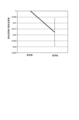
- Figure 6 shows the experimental results of measurements made using the second method before and after the cooling load was applied. Comparing the results before and after the cooling load was applied, it was confirmed that the pulse amplitude in the nose area, taken against the pulse wave amplitude w in the forehead area, showed a downward trend.
- the error bars on the graph represent the standard deviation of the measured values of the 13 samples in both the positive and negative directions.
- the estimation results of the state of the autonomic nerves obtained by the two measurement methods are used in combination according to the shooting time, and a weighted average estimation result (third estimation result) is obtained.
- the weighting may be, for example, a simple linear change with respect to the shooting time, but is not limited to this.
- the weighting for the result of the first method is zero when the shooting time is 30 seconds or less, increases linearly between 30 seconds and 5 minutes (300 seconds), and becomes 100% when the shooting time is 5 minutes or more.
- the weighting for the result of the second method is inversely correlated with the weighting for the result of the first method. In other words, the shorter the shooting time, the higher the weighting of the first estimation result, and the longer the shooting time, the smaller the weighting.
- the weighting of the first estimation result is 0%.
- Factors that cause fluctuations include, for example, blurring of the field of view. When the electronic device 10 is held in the hand, for example, blurring of the shooting direction is likely to occur. Factors that cause fluctuations may also include the subject's movement, for example, changes in the angle of the face. Factors that cause fluctuations in external light, for example, the movement of clouds outdoors, or the movement of a reflector that reflects incident light or an obstruction passing in front of a window. If any of the above factors that cause fluctuations are detected, the use of the captured image is discontinued immediately before the detection, and the time up to that time is regarded as the duration of detection (P11).
- the server device 50 detects and evaluates the above-mentioned fluctuation factors.
- information on the stability of the attention area image may be attached to the transmitted attention area image.
- information on the change in the range cut out from the photographed image, the change in the positional relationship of the feature points used for cutting, etc. may be quantified and attached to the attention area image. If the photographed image or the attention area image is no longer stable due to the above-mentioned fluctuation factors during the course of the photographed image or the attention area image, the acquisition of the photographed image and the estimation of the autonomic nerve state may be terminated at that point.
- the time until the termination is the duration of the photographed image that is stably obtained.
- the image data for the entire duration may not be used for the estimation of the autonomic nerve state by the second method.
- the time width used for the estimation of the autonomic nerve state by the first method and the estimation of the autonomic nerve state by the second method may be different as long as the reference time overlaps.
- the weighting is determined based on that duration.
- the autonomic nerve state obtained in the processes of P6 and P8 is weighted and averaged accordingly (P9).
- the estimation result of the autonomic nerve state obtained in this manner does not have to be output as is.
- the estimation result obtained may be further classified into several stress levels, for example, about 3 to 5 levels, and a symbol, code, or sign corresponding to the stress level may be output as the estimation result (P10).
- FIG. 7 is a flowchart showing the control procedure of the state estimation control process executed by the CPU 51 of the server device 50.
- the state estimation control process which is an information processing method of this embodiment, is an example of processing when the server device 50 receives a captured image as is.
- the CPU 51 reads out and executes this state estimation control process from the program 531.
- the CPU 51 acquires image data received by the communication unit 55 (S1).
- the CPU 51 detects a face from each image data (S2).
- the CPU 51 sets feature points in the detected face, sets a region of interest based on the feature points, and extracts an image of the set region of interest (S3; acquisition means).
- the CPU 51 identifies the fluctuation in the luminance value of the green wavelength band in the image of each region of interest (S4).
- the CPU 51 determines the detection time based on the degree of blurring of the image of each region, etc. (S5).
- the CPU 51 calculates the range of the identified variation for each region of interest (S6; calculation means).
- the CPU 51 calculates a first estimation result based on the ratio of the ranges of variation for each region thus calculated (S7; estimation means).
- the CPU 51 calculates the frequency spectrum of the identified fluctuation and calculates the spectral intensity in each of the HF and LF bands (S8).
- the CPU 51 obtains a second estimation result indicating the state of the autonomic nerves based on the ratio of these spectral intensities (S9).
- the CPU 51 obtains a weighting coefficient based on the determined detection time. Based on the obtained weighting coefficient, the CPU 51 calculates a weighted average value of the first estimation result and the second estimation result to determine a third estimation result (S10).
- the CPU 51 determines the stress index to be output according to the third estimation result, and outputs it as the estimation result (S11).
- the estimation result is output to the electronic device 10 that requested the result.
- the CPU 51 also stores the estimation result in the history information 532 together with the estimation time and the identification information of the electronic device 10 that requested the result.
- the stored estimation result does not have to be limited to the final one according to the third estimation result.
- the history information 532 may store the first to third estimation results together.
- the CPU 51 may refer to the history information 532 and output a comparison result between the autonomic nerve state at the most recent timing and the autonomic nerve state at the previous timing (before the most recent timing), or a tendency of change such as maintenance, deterioration, or improvement of the autonomic nerve state over a longer period of time.
- the CPU 51 ends the state estimation control process.
- steps S1 to S3 may be executed by the CPU 11 of the electronic device 10, and then the server device 50 may obtain the processed data of S3.
- the CPU 51 of the server device 50 may then execute steps S4 and onward based on the acquired data.
- the server device 50 which is the information processing device of this embodiment includes a CPU 51 (CPU 11 in the case of the electronic device 10; the same applies below).
- the CPU 51 acquires continuous photographed images (images of the area of interest) in two areas of the human body: a first area in which the skin blood flow is easily influenced by the autonomic nerves, and a second area in which the skin blood flow is not easily influenced by the autonomic nerves. Being easily influenced by the autonomic nerves means that there are many AVA blood vessels.
- the CPU 51 calculates the amplitude of the signal corresponding to the pulse wave in the two areas, here the amplitude of the luminance fluctuation of the green component.
- the CPU 51 obtains a first estimation result of the state of the autonomic nerves from the relative value, for example the ratio, of the amplitudes in the two areas.
- the second method of this embodiment is simple because the estimation result is obtained from the photographed image.
- the amplitude of the blood flow fluctuation is obtained in pulse units, multiple measurement results can be obtained even in a few to 10 seconds. Therefore, the second method of this embodiment can easily obtain results in a short time, reducing the inconvenience to the user.
- this second method can reduce the effects of external fluctuations through short-time detection, and therefore the conditions required for imaging are relaxed. In other words, it is not necessary to fix the imaging unit in a place where the incident light does not fluctuate for a long period of time.
- this second method can also reduce the psychological impact of preparing the imaging environment and having the person maintain a posture for a long period of time.
- the CPU 51 may also calculate the fluctuation intensity of the period (pulse period) of the fluctuation of the reflected light intensity (signal) in the green wavelength band corresponding to the pulse wave (pulse) with respect to frequency based on successive captured images of the third region of the human body.
- the CPU 51 obtains a second estimation result for the state of the autonomic nerves from the relative value (ratio) of the first fluctuation intensity in the first frequency band (HF band) and the second fluctuation intensity in the second frequency band (LF band).
- the CPU 51 obtains a third estimation result for the state of the autonomic nerves by using the first estimation result and the second estimation result in combination.
- Complementary results can be obtained by using the first estimation result, which is easily obtained in a short period of time, and the second estimation result, which is conventionally used and highly reliable but difficult to obtain accuracy in a short period of time, in combination. Therefore, this server device 50 can suppress a decrease in the accuracy of the estimation result obtained in a short period of time.
- the CPU 51 may also obtain a third estimation result by taking a weighted average of the first estimation result and the second estimation result. By appropriately weighting the estimation results according to their respective reliability conditions, it is possible to reduce the degree to which the results are off and improve their reliability.
- the weighted average may be set so that the shorter the shooting time of the captured image, the greater the weight of the first estimation result. Since the accuracy of the second estimation result depends on the shooting time, the first estimation result may be prioritized when the shooting time is short, and the second estimation result may be prioritized when the shooting time is long. By setting the weights in this manner, the server device 50 can improve the accuracy of the estimation results it outputs.
- the shooting time may also be determined based on the duration over which a stable captured image is being obtained.
- the image becomes blurred or disturbances are introduced during long-term shooting, noise in the captured image increases, reducing the accuracy of the estimation. Therefore, by selecting a portion of the input captured image that is stably captured and using that portion for the estimation, it is possible to suppress degradation of the estimation result due to noise.
- the third region may include at least one of the first region and the second region. In other words, it is not necessary to make the range of the captured image different between the first method and the second method. By analyzing the same range with different methods to obtain respective results, the server device 50 can reduce factors that cause the results to differ. In addition, there is no need to increase the amount of work required for image processing due to an increase in the number of captured locations.
- the CPU 51 may also cut out the captured images of the two regions from the captured image of the face. There are several regions on the human body that have many AVA blood vessels, but if the face is originally exposed, it is easy to capture them. Also, since the first and second regions are captured side by side, it is easy to set the capture range.
- the two areas may also be the forehead and nose. As both are particularly in the front of the face, the photographer can take the picture while facing the imaging unit. This makes it less likely that unintended external light will be present, and makes it easier to obtain an image with an appropriate amount of light.
- the CPU 51 may also be able to compare the most recent first estimation result with the first estimation result obtained prior to this result to obtain changes in the state of the autonomic nerves.
- the information processing method of this embodiment also includes the following processes: (1) Obtaining successive images of two regions of the human body: a first region where skin blood flow is easily affected by the autonomic nerves, and a second region where skin blood flow is less affected by the autonomic nerves. (2) Calculating the amplitudes of signals corresponding to the pulse waves in the two regions, particularly the luminance time-series signal of the green component. (3) Obtaining a first estimation result for the state of the autonomic nerves from the ratio of the amplitudes in the two regions. According to this information processing method, estimation results can be obtained from images captured in a short time, making measurement easy. Therefore, this information processing method can reduce the hassle of the user having to remain still for a long time and having to set up the environment to obtain stable images for a long time.
- the server device 50 is described as analyzing the state of the autonomic nerves and obtaining an estimation result.
- the analysis and obtaining the estimation result may be performed by the electronic device 10. In other words, all processing from capturing an image of the face to estimation may be completed within the electronic device 10.
- the first method which takes time but has been used in the past and is reliable
- the second method which can be performed easily and quickly, are used in combination, but this is not limited to this.
- the shooting time is limited to a short period of time
- only the second method may be used from the beginning.
- the nose has been described as an example of an area with many AVA blood vessels, but this is not limiting.
- ears can also be cited as an area with many AVA blood vessels.
- the subject to be photographed does not have to be the face. Even in the case of a face, it does not have to be an image of the entire face as long as the area of interest (forehead and nose) is included. An image detection algorithm different from the above may be used to identify the area of interest in accordance with these.
- the above processing does not have to be real-time processing. If it is not necessary to immediately inform the user of the estimation results, images for one or more appropriate estimation times (ranges) may be extracted in sequence from the obtained long-term shooting data, and the autonomic nerve state may be estimated for each of them.
- a weighted average according to the duration of the results obtained by the two methods is used, but this is not limited to this.
- the degree of stability during the application period of the first method and the application period of the second method may be quantitatively evaluated and taken into consideration in the weighting.
- weighting may not be used at all and a uniform additive average may be used.
- the index in the second method is calculated from the ratio of the amplitudes of the luminance time-series signals, but this is not limited to this. Any value other than the ratio may be used as long as it indicates the relative relationship between the amplitudes in the two regions (relative value).
- the frequency ranges of the HF and LF bands may deviate from the ranges of the above embodiment.
- the stability of the image may be evaluated not only based on the content of the captured image, but also based on the measurement results of other sensor devices such as an acceleration sensor, tilt sensor, or light quantity sensor of the electronic device 10.
- the image was captured by the image capture unit 14 included in the electronic device 10, but this is not limited to the above. Images may also be captured by connecting a camera to the electronic device 10 or the server device 50 as a peripheral device.
- the storage unit 53 including a non-volatile memory such as an HDD or a flash memory has been described as an example of a computer-readable medium for storing the program 531 related to the state estimation control of the present disclosure, but is not limited thereto.
- other computer-readable media other non-volatile memories such as MRAM and portable recording media such as CD-ROMs and DVD disks can be applied.
- a carrier wave is also applied to the present disclosure as a medium for providing data of the program related to the present disclosure via a communication line.
- the specific configurations, contents and procedures of the processing operations, etc. shown in the above embodiments can be modified as appropriate without departing from the spirit of the present disclosure.
- the scope of the present disclosure includes the scope of the invention described in the claims and its equivalents.
- This disclosure can be used in information processing devices, information processing methods, and programs.
Landscapes
- Health & Medical Sciences (AREA)
- Life Sciences & Earth Sciences (AREA)
- Engineering & Computer Science (AREA)
- Animal Behavior & Ethology (AREA)
- Heart & Thoracic Surgery (AREA)
- Veterinary Medicine (AREA)
- Public Health (AREA)
- General Health & Medical Sciences (AREA)
- Surgery (AREA)
- Physics & Mathematics (AREA)
- Molecular Biology (AREA)
- Biophysics (AREA)
- Pathology (AREA)
- Biomedical Technology (AREA)
- Medical Informatics (AREA)
- Educational Technology (AREA)
- Developmental Disabilities (AREA)
- Social Psychology (AREA)
- Child & Adolescent Psychology (AREA)
- Psychology (AREA)
- Psychiatry (AREA)
- Hospice & Palliative Care (AREA)
- Cardiology (AREA)
- Physiology (AREA)
- Measurement Of The Respiration, Hearing Ability, Form, And Blood Characteristics Of Living Organisms (AREA)
- Measuring Pulse, Heart Rate, Blood Pressure Or Blood Flow (AREA)
Abstract
より簡便に自律神経状態を判定することのできる情報処理装置、情報処理方法及びプログラムを提供する。情報処理装置は、制御部を備える。制御部は、人体において皮膚血流が自律神経の影響を受けやすい第1領域と、皮膚血流が自律神経の影響を受けにくい第2領域と、の2つの領域における連続的な撮影画像を取得する。制御部は、2つの領域における脈波に応じた信号の振幅をそれぞれ算出する。制御部は、2つの領域における振幅の相対値により自律神経の状態についての第1推定結果を得る。
Description
本開示は、情報処理装置、情報処理方法及びプログラムに関する。
従来、人体の自律神経の状態、特にストレス度合を判断する技術がある。緊張度合が高いと、交感神経の優位な状態となる。緊張度合は、脈拍間隔の揺らぎ状態から判断できることが知られている。また、特許文献1には、遠赤外線及び近赤外線で顔面を撮影し、緊張に応じた温度分布の変化に基づいてストレスの有無を推定する技術が開示されている。
しかしながら、従来技術では、自律神経状態の検出に長い測定時間や複数波長の赤外線センサといった設備が必要となり、手間がかかるという課題がある。
本開示の目的は、より簡便に自律神経状態を判定することのできる情報処理装置、情報処理方法及びプログラムを提供することにある。
上記目的を達成するため、本開示は、
人体において皮膚血流が自律神経の影響を受けやすい第1領域と、皮膚血流が自律神経の影響を受けにくい第2領域と、の2つの領域における連続的な撮影画像を取得し、
前記2つの領域における脈波に応じた信号の振幅をそれぞれ算出し、
前記2つの領域における前記振幅の相対値により自律神経の状態についての第1推定結果を得る制御部
を備える情報処理装置である。
人体において皮膚血流が自律神経の影響を受けやすい第1領域と、皮膚血流が自律神経の影響を受けにくい第2領域と、の2つの領域における連続的な撮影画像を取得し、
前記2つの領域における脈波に応じた信号の振幅をそれぞれ算出し、
前記2つの領域における前記振幅の相対値により自律神経の状態についての第1推定結果を得る制御部
を備える情報処理装置である。
本開示に従うと、より簡便に自律神経状態を判定することができるという効果がある。
以下、実施の形態を図面に基づいて説明する。
図1は、本実施形態の状態推定システム100の構成を示す図である。
状態推定システム100は、電子機器10と、サーバ装置50とを備える。
図1は、本実施形態の状態推定システム100の構成を示す図である。
状態推定システム100は、電子機器10と、サーバ装置50とを備える。
電子機器10は、ユーザが手軽に利用可能なものであって、かつ動画又は連続的な画像を撮影可能なものである。電子機器10は、例えば、スマートフォンである。
サーバ装置50は、本実施形態の情報処理装置であり、電子機器10から動画又は連続的な画像の画像データを受信して、自律神経の状態を推定する。サーバ装置50は、受信した画像の画像を処理可能な演算能力及びメモリ容量があればよく、普通のコンピュータ(PC;Personal Computer)であってもよい。
電子機器10及びサーバ装置50の間では、上記画像データの通信が可能な通信速度で通信を行う。通信は、電子機器10とサーバ装置50の間で直接なされなくてもよい。すなわち、通信は、無線LANのルータ、有線のLANケーブルやインターネットなどを介してもよい。例えば、電子機器10及びサーバ装置50は、無線LAN(Local Area Network)により通信が可能である。あるいは、電子機器10及びサーバ装置50は、ブルートゥース(登録商標)の高速通信規格(HSモード)などにより直接通信が可能であってもよい。
なお、1台のサーバ装置50は、複数台の電子機器10の撮影画像を取得して、各々自律神経の状態を推定することができてもよい。
図2Aは、電子機器10の機能構成を示すブロック図である。電子機器10は、CPU11(Central Processing Unit)と、RAM12(Random Access Memory)と、記憶部13と、撮影部14と、通信部15と、表示部16と、操作受付部17などを備える。
CPU11は、演算処理を行い、電子機器10の動作を統括制御するプロセッサである。CPU11は、単一のプロセッサを有していてもよい。あるいは、CPU11は、複数のプロセッサが並列に演算処理を行ってもよいし、複数のプロセッサが用途に応じて各々独立して演算処理を行ってもよい。RAM12は、CPU11に作業用のメモリ空間を提供し、一時データを記憶する。
記憶部13は、制御プログラムや設定データなどを記憶する不揮発性メモリである。不揮発性メモリは、例えば、フラッシュメモリなどであってもよい。
撮影部14は、光を入射させる光学系と、入射光を各画素位置で検出する露光部と、検出した光量分布に基づいて画像データを生成、出力する画像出力部と、を有するカメラである。撮影部14は、動画の撮影が可能である。動画は、後述のように、脈拍に応じた変化を精度よく検出するのに必要なフレームレートである。撮影部14は、例えば、30fps程度の動画が撮影可能である。
通信部15は、上記のようにサーバ装置50との間で画像データの通信を行う。通信部15は、例えば、無線LANのためのネットワークカードと、アンテナとを有する。
表示部16は、CPU11の制御に基づいて表示画面に各種情報などを表示する。表示画面は、例えば、液晶ディスプレイ又は有機EL(Electro-Luminescent)ディスプレイなどであるが、これに限られない。
操作受付部17は、外部からの入力操作を受け付ける。操作受付部17は、例えば、表示画面と重なって位置するタッチパネル及び電子機器10の側面などに位置する押しボタンスイッチなどを有する。操作受付部17は、その他のスイッチ、例えば、スライドスイッチなどを有していてもよい。
図2Bは、サーバ装置50の機能構成を示すブロック図である。サーバ装置50は、CPU51(Central Processing Unit)(制御部)と、RAM52(Random Access Memory)と、記憶部53と、通信部55と、表示部56と、操作受付部57などを備える。
CPU51は、演算処理を行い、サーバ装置50の動作を統括制御するプロセッサである。CPU51は、単一のプロセッサを有していてもよい。あるいは、CPU51は、複数のプロセッサが並列に演算処理を行ってもよいし、複数のプロセッサが用途に応じて各々独立して演算処理を行ってもよい。RAM52は、CPU51に作業用のメモリ空間を提供し、一時データを記憶する。
記憶部53は、制御プログラムや設定データなどを記憶する不揮発性メモリである。不揮発性メモリは、例えば、HDD(Hard Disk Drive)及び/又はフラッシュメモリなどであってもよい。記憶部53には、自律神経の状態推定に係るプログラム531と、推定された自律神経状態の履歴データをまとめた履歴情報532などが記憶されている。記憶部53は、内蔵の補助記憶装置に限られない。サーバ装置50に外付けされた補助記憶装置であってもよいし、ネットワーク上に位置するドライブであってもよい。あるいは、クラウドサーバなどが記憶部53として用いられてもよい。なお、プログラム531が内蔵の補助記憶装置に記憶され、履歴情報532がネットワークドライブやクラウドサーバなどの外部に記憶されてもよい。
通信部55は、上記のように電子機器10との間で画像データの通信及び推定結果などの送受信を行う。通信部55は、例えば、電子機器10が無線LANにより接続するルータとの間でのLANによる通信のためのネットワークカードを有する。
表示部56は、CPU51の制御に基づいて表示画面に各種情報などを表示する。表示画面は、例えば、液晶ディスプレイ又は有機EL(Electro-Luminescent)ディスプレイなどであるが、これに限られない。
操作受付部57は、外部からの入力操作を受け付ける。操作受付部57は、例えば、キーボード、ポインティングデバイス及び押しボタンスイッチなどを有する。ポインティングデバイスは、例えば、マウスである。操作受付部17は、その他のスイッチ、例えば、スライドスイッチなどを有していてもよい。なお、表示部56及び操作受付部57は、サーバ装置50に対して外付けされる周辺機器であってもよい。また、通信部55の代わりにUSBメモリなどの可搬型媒体を介して画像データなどを取得することも可能である。すなわち、本実施形態のコンピュータとしてのサーバ装置50は、少なくともCPU51と、RAM52と、記憶部53とを備える。
次に、状態推定システム100における自律神経の状態推定動作について説明する。本実施形態の状態推定システム100は、顔の可視光画像から交感神経と副交感神経のどちらが優位であるかを検出する手法を2種類併用する。
図3は、自律神経の状態推定動作の流れについて説明する図である。
状態推定システム100では、各端末である電子機器10が、ユーザ自身又は推定対象者の顔面(頭部)を動画撮影する(P1)。撮影データから顔が検出される(P2)。検出は、周知の画像認識アルゴリズムを用いて行われればよい。顔を認識する画像認識アルゴリズムとしては、例えば、機械学習にAdaboostを用いたViola-Jones法が挙げられる。
状態推定システム100では、各端末である電子機器10が、ユーザ自身又は推定対象者の顔面(頭部)を動画撮影する(P1)。撮影データから顔が検出される(P2)。検出は、周知の画像認識アルゴリズムを用いて行われればよい。顔を認識する画像認識アルゴリズムとしては、例えば、機械学習にAdaboostを用いたViola-Jones法が挙げられる。
顔が検出されると、顔の各構成要素の範囲を示す特徴点を定める。特徴点は、例えば、目の周囲、鼻の下及び鼻筋、上下の唇の周囲、眉毛、顎のラインなどを適宜な数で規定するものである。
これらの特徴点のうち、特定の点を基準として本実施形態における注目領域を規定する(P3)。注目領域は、額及び鼻である。額領域は、眉毛を示す特徴点と、顔輪郭の上端、すなわち前髪の下端との境界の間に規定され得る。鼻領域は、鼻の下の各点と、鼻筋の上端の点とにより規定され得る。鼻領域の画像サイズは、撮影画像における鼻の大きさに依存する。額領域の画像サイズは、必ずしも鼻領域の画像サイズと統一されなくてもよい。一般的に、画像サイズが大きいほどノイズの影響を低減しやすい。したがって、額領域は、顔の他の部分と十分に分離できる範囲で大きく定められてもよい。
電子機器10は、規定された注目領域を各フレームの顔画像から切り出して、注目領域画像(連続的な撮影画像)としてサーバ装置50に送る。この際、動画又は連続静止画の画像フォーマットは、撮影時のものから変更されてもよい。なお、本実施形態では、注目領域を切り出した後の画像解像度は、必ずしも高解像度であることが要求されない。したがって、注目領域画像は、画像解像度が撮影時よりも低下したものであってもよい。
後述のように、鼻領域は、人体において皮膚血流が自律神経の影響を強く受ける(受けやすい)領域(第1領域)である。額領域は、皮膚血流が自律神経の影響を受けにくい領域(第2領域)である。これら2つの領域の注目領域画像が各々切り出されることで、当該2つの領域の特徴が比較されやすくなる。
なお、上記P2~P3の処理は、必ずしも電子機器10で実行されなくてもよい。電子機器10は、単純に撮影画像をサーバ装置50へ送信してもよい。どちらでP2~P3の処理が行われるかが選択可能であってもよい。例えば、電子機器10のCPU11の処理能力、及び電子機器10とサーバ装置50との間の通信速度などに応じて、個別に設定されてもよい。あるいは、ユーザの操作受付部17への入力操作による設定に応じて直接的に切り替えられてもよい。
サーバ装置50では、注目領域画像から脈波を抽出する(P4)。人体では、脈拍に応じて血管の周期的な拡張と収縮が生じる。血液中のヘモグロビンは、特定の波長帯、例えば、緑色波長帯や赤外の光を良く吸収するので、顔における反射光は、脈拍に応じて周期的にこれらの波長帯の成分が増減する。撮影画像からこの成分、ここでは緑色成分の周期的な変動を検出することで、脈波が抽出される。脈拍は、1分当たりの回数が、直近の10-15秒程度の期間における平均周期に基づいて求められればよい。
図4A及び図4Bは、脈拍の揺らぎについて説明する図である。
脈拍は、たとえ安静にしていてもそのパルスの間隔が一定ではなく、変動している。図4Aにおいて、T1~T6はそれぞれの脈拍の間隔である。これらの間隔は、互いに等しい値ではなく、不規則に変化している。この脈拍間隔の変化、すなわち揺らぎを周波数分析すると、図4Bに示すように、0.04-0.15Hzの範囲の周波数(LF帯、第2の周波数帯)と、0.15-0.40Hzの範囲の周波数(HF帯、第1の周波数帯)のそれぞれにピークが現れることが知られている。
これらLF帯のパワー値(第2揺らぎ強度)とHF帯のパワー値(第1揺らぎ強度)との相対的な関係を規定した値(相対値)、例えば、比「LF/HF」により自律神経状態を判定する手法が知られている。一般的な人間は、ストレスや緊張状態にあるときには、自律神経のバランスが交感神経優位となり、LF/HFの値が増加する。逆にリラックス状態のときには、自律神経のバランスが副交感神経優位となり、LF/HFの値が減少する。したがって、脈拍間隔の揺らぎにおけるHF帯のパワー値と、LF帯のパワー値との比をとることにより、自律神経系において交感神経と副交感神経のいずれが優位な状態であるか、すなわちストレスの度合(第2推定結果)が得られる。なお、各周波数帯のパワー値で表される揺らぎの大きさ(揺らぎ強度)は、個人の特性(年齢性別など)及び体質などにも依存するので、数値は、必ずしも異なる個人の間で単純比較できるものではない。また、同一の者であっても、疲労などに応じて数値には多少の変動が生じ得るので、注意が必要である。
このような脈拍間隔の揺らぎに基づいて自律神経の状態、特にストレスの度合を推定する第1手法は、古くから知られており、信頼性もある。この場合、自律神経の状態推定には、第3領域の画像が用いられる。第3領域の画像には、第1領域及び第2領域のうちいずれか一方の領域の画像のみが用いられてもよいし、第1領域及び第2領域の両方の領域の画像が併用されてもよい。あるいは、第1手法による自律神経の状態推定には、第1領域及び第2領域を含まない他の領域の画像が用いられてもよいし、第1領域又は第2領域のいずれか又は双方を含む、例えば、顔全体の画像が用いられてもよい。検出された脈波の周波数揺らぎを特定して(P5)、LF帯及びHF帯の2つの周波数帯のパワー比に基づいて、自律神経の状態が推定される(P6)。しかしながら、この第1手法では、最長0.04Hz,すなわち25秒周期程度の変動を複数回安定して得る必要がある。したがって、ある程度精度の高い推定結果を得るには、数分~5分程度の安定した画像撮影と当該画像の解析が必要となり、ユーザの時間と手間がかかる。
これに対し、本実施形態の状態推定システム100では、上記第1手法に加えて、短時間で簡易的に自律神経の状態の判別が可能な第2手法が併用される。図3に戻って、上記2つの注目領域のうち、鼻領域は、動静脈吻合血管(AVA血管)の多い領域である。AVA血管の多い領域は、皮膚血流が自律神経状態の影響を受けやすく、緊張状態では、血管が閉じて、血流が低下する。その結果、脈拍に応じた緑色波長帯の光量の変動振幅が小さくなると想定される。一方、額領域では、このような自律神経による影響は小さい。したがって、緑色波長帯の光量の変動の振幅には大きな変化は生じない。
このような領域間での違いにより、画像から抽出した脈波に関して、額領域における振幅に対する鼻領域における振幅の比には、自律神経状態に応じた変動が現れることになる。すなわち、この振幅の比により、ストレス度合(自律神経の状態)を示す結果(第1推定結果)が得られる。上記の脈拍間隔ゆらぎの場合と同様に、異なる部位間での脈波振幅の比の変動も、個人の特性及び体の疲れなどの状態に依存する。また、光量の絶対値は、撮影環境に依存する。したがって、各領域の反射光の光量をその単独で自律神経の状態の推定に用いることは困難である。一方で、この指標は、上記の通り、同一画像における第1領域の反射光と第2領域の反射光の変動から得られる輝度時系列信号(信号)の振幅の比から求められる。このため、この指標は、撮影環境の影響を受けにくい。また、この第2手法は、複数回の脈拍、すなわち、5-10秒程度で結果を得ることができる。
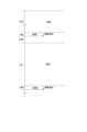
図5には、第2手法における計測の実験手順を示す。計測の前に計測対象者は20分間、安静状態が維持される。その後、10秒間計測対象者の顔が撮影されて、各注目領域における緑色波長帯の光の強度振幅が測定される。撮影から20秒経過後、計測対象者に対してストレスとなる負荷が2分間与えられる。その後再度、計測対象者が10秒間撮影される。
実験で直接的かつ即座にストレスを与え得る負荷としては、物理的な痛覚を与えるものと、心理的な不快感を与えるものとがある。心理的な不快感には、騒音、振動、不快な画像や臭いなど、触覚以外の感覚に与えられるものが含まれる。人体実験上、あまり強くない負荷として、手を冷水に浸すものが採用された。また、ストレスは多分に被験者の精神状態に依存する。したがって、被験者の初期状態によっては、ストレスの増大につながっていないケースがあり得る。
図6は、負荷前後の第2手法による計測の実験結果を示す。冷却負荷を与える前と与えた後とを比較すると、額領域の脈波振幅w基準とした鼻領域の脈拍振幅は、低下傾向にあることが確認された。本グラフは、サンプル数N=13における平均値より得られた。グラフのエラーバーは、13サンプルの測定値の標準偏差を正負両方向に付けたものである。
図3に戻り、本実施形態の状態推定システム100では、額領域と鼻領域でそれぞれ脈拍に応じた光量変化の振幅を特定する(P7)。額領域における振幅に対する鼻領域における振幅の比により、第2手法による自律神経の状態が推定される(P8)。
上記のように、撮影(計測)時間が伸びるほど、従来の第1手法による精度が、第2手法に比して相対的に向上する。したがって、本実施形態では、撮影時間に応じて2つの計測手法で得られた自律神経の状態の推定結果を併用、特に重み付け平均した推定結果(第3推定結果)を得る。重み付けは、例えば、単純に撮影時間に対する直線変化であってもよいが、特にこれに限られるものではない。例えば、第1手法の結果に対する重みは、撮影時間が30秒以下ではゼロであり、30秒から5分(300秒)の間で直線状に増加し、撮影時間5分以上では100%となる。第2手法の結果に対する重みは、第1手法の結果に対する重みと反相関となる。すなわち、撮影時間が短いほど、第1推定結果の重みが大きく、撮影時間が長くなるにつれて重みが小さくなっていく。5分以上の撮影画像が安定して得られた場合には、第1推定結果の重みは0%となる。
ここでは、上記のように、撮影画像の単純な継続時間ではなく、安定性が評価に重要である。このために、撮影画像における光量の変動要因が別途検出される。変動要因には、例えば、撮影視野のぶれが含まれる。電子機器10が手で保持されている場合などは、撮影方向などにぶれが生じやすい。また、変動要因には、対象者の動き、例えば顔の角度の変化が含まれ得る。さらに、変動要因には、外光の変動、例えば、屋外の雲の動き、あるいは入射光を反射する反射体や窓の前などを横切る遮蔽体などの動きなどが含まれ得る。上記変動要因が検出された場合には、検出の直前のタイミングで撮影画像の利用を打ち切って、当該タイミングまでの時間を検出の継続時間とする(P11)。
撮影画像からの注目領域の切り抜きがサーバ装置50で行われる場合には、サーバ装置50が上記変動要因の検出及び評価を行う。撮影画像からの注目領域の切り抜きが電子機器10で行われる場合には、送信される注目領域画像に対し、注目領域画像の安定度合に関する情報が付されてもよい。例えば、撮影画像から切り抜かれる範囲の変化や、切り抜きに用いられる特徴点の位置関係の変化などについての情報が数値化されて、注目領域画像に付されてもよい。撮影画像又は注目領域画像の途中で上記の変動要因により安定した画像といえなくなった場合には、その時点で、撮影画像の取得及び自律神経状態の推定を打ち切ってもよい。この場合には、打ち切られるまでの時間が安定して得られている撮影画像の継続時間である。なお、得られた継続時間が長い場合、例えば、30秒以上の場合に、第2手法による自律神経状態の推定には、継続時間の全体の画像データが用いられなくてもよい。すなわち、第1手法による自律神経状態の推定と、第2手法による自律神経状態の推定とは、基準時刻さえ重なっていれば、推定に利用される時間幅が異なっていてもよい。
このようにして、推定に用いられる撮影画像の継続時間が決定されると、当該継続時間に基づいて上記重み付けが決定される。これに応じて、P6,P8の処理で得られた自律神経の状態が重み付け平均される(P9)。このようにして得られた自律神経の状態の推定結果は、そのまま出力されなくてもよい。、得られた推定結果がさらに数段階、例えば、3~5段階程度のストレスレベルに分類されて、ストレスレベルに応じた記号、符号又は標識などが推定結果として出力されてもよい(P10)。
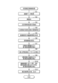
図7は、サーバ装置50のCPU51が実行する状態推定制御処理の制御手順を示すフローチャートである。本実施形態の情報処理方法である状態推定制御処理は、撮影画像をそのままサーバ装置50が受信した場合の処理の例である。CPU51は、自律神経状態の推定結果の要求とともに撮影画像が取得された場合に、この状態推定制御処理をプログラム531から読み出して実行する。
CPU51は、通信部55が受信した画像データを取得する(S1)。CPU51は、各画像データから顔を検出する(S2)。CPU51は、検出された顔における特徴点を設定し、当該特徴点に基づいて注目領域を設定し、設定された注目領域の画像を抽出する(S3;取得手段)。
CPU51は、各注目領域の画像において、緑色波長帯の輝度値の変動を特定する(S4)。CPU51は、各領域の画像のぶれ具合などに基づいて、検出時間を決定する(S5)。
CPU51は、特定された変動の幅を各注目領域でそれぞれ求める(S6;算出手段)。CPU51は、求められた各領域の変動の幅の比に基づいて、第1推定結果を算出する(S7;推定手段)。
CPU51は、特定された変動の周波数スペクトルを算出して、HF帯及びLF帯のそれぞれにおけるスペクトル強度を算出する(S8)。CPU51は、これらのスペクトル強度の比に基づいて、自律神経の状態を示す第2推定結果を得る(S9)。
CPU51は、決定されている検出時間に基づく重み付け係数を取得する。CPU51は、取得した重み付け係数に基づいて、第1推定結果及び第2推定結果の重み付け平均値を算出して第3推定結果を定める(S10)。
CPU51は、第3推定結果に応じて、出力するストレス指標を決定し、推定結果として出力する(S11)。推定結果の出力先は、結果要求のあった電子機器10である。また、CPU51は、推定結果を推定時刻や要求のあった電子機器10の識別情報とともに履歴情報532に記憶させる。記憶される推定結果は、第3推定結果に応じた最終的なものに限られなくてもよい。履歴情報532には、第1推定結果~第3結果がまとめて記憶されてもよい。CPU51は、履歴情報532を参照して、直近のタイミングにおける自律神経の状態と前回(直近のタイミングより前)の自律神経の状態との比較結果、又はより長い期間における自律神経状態の維持、悪化、改善といった変化の傾向などを併せて出力してもよい。CPU51は、状態推定制御処理を終了する。
なお、上記の通り、処理S1~S3の処理が電子機器10でCPU11により実行されてから、S3の処理済データをサーバ装置50が得てもよい。サーバ装置50のCPU51が、取得データに基づいて処理S4以降の処理を実行する。
以上のように、本実施形態の情報処理装置であるサーバ装置50(一部は電子機器10であってもよい)は、CPU51(電子機器10の場合にはCPU11。以下同じ)を備える。CPU51は、人体において皮膚血流が自律神経の影響を受けやすい第1領域と、皮膚血流が自律神経の影響を受けにくい第2領域との2つの領域における連続的な撮影画像(注目領域画像)を取得する。自律神経の影響を受けやすいとは、AVA血管が多いことを意味する。CPU51は、2つの領域における脈波に応じた信号、ここでは、緑色成分の輝度変動の振幅をそれぞれ算出する。CPU51は、2つの領域における振幅の相対値、例えば比により自律神経の状態についての第1推定結果を得る。このように、本実施形態の上記第2手法は、撮影画像から推定結果が得られるので、簡便である。特に、血流変動の振幅が脈拍単位で得られるので、数秒~10秒程度でも複数の計測結果を得ることができる。したがって、本実施形態の第2手法では、短時間で容易に結果を得ることができ、ユーザの煩わしさを低減させることができる。特に、この第2手法では、短時間の検出により外部変動の影響を低減することができるので、撮影に必要な条件が緩和される。すなわち、長い時間入射光が変動しない場所で撮影部を固定しなくてもよい。また、長い時間撮影対象である人が静止している必要がない。これらにより、測定環境を整備する手間が低減される。さらに、この第2手法では、撮影環境を整えたり本人が長い時間姿勢を維持したりすることによる心理面への影響も低減させることができる。
また、CPU51は、人体の第3領域における連続的な撮影画像に基づいて、脈波(パルス)に応じた緑色波長帯の反射光強度(信号)の変動の周期(パルス周期)の揺らぎ強度を周波数に対して算出してもよい。CPU51は、第1の周波数帯(HF帯)における第1揺らぎ強度と、第2の周波数帯(LF帯)における第2揺らぎ強度と、の相対値(比)により自律神経の状態についての第2推定結果を得る。CPU51は、第1推定結果と第2推定結果とを併用して自律神経の状態についての第3推定結果を得る。短期間で簡易的に得られる第1推定結果と、従来用いられていて信頼性も高いが短期間では精度が得られづらい第2推定結果とを併用することで、相補的な結果が得られる。したがって、このサーバ装置50は、短時間で得る推定結果の精度の低下を抑えることができる。
また、CPU51は、第1推定結果と第2推定結果の重み付け平均により第3推定結果を得てもよい。推定結果の各々の信頼性の状況に応じて適切に重み付けすることで、結果の外れ度合いを低減させて信頼性を向上させることができる。
また、重み付け平均は、撮影画像の撮影時間が短いほど第1推定結果の重みが大きく定められてもよい。第2推定結果の精度は、撮影時間に依存するので、撮影時間が短時間である場合には第1推定結果を優先し、撮影時間が長時間得られた場合には、第2推定結果を優先してもよい。このように重みが定められることで、サーバ装置50は、出力する推定結果の精度を向上させることができる。
また、撮影時間は、撮影画像が安定して得られている継続時間に基づいて定められてもよい。特に長時間の撮影の間で画像がぶれたり外乱が混入したりすると、撮影結果のノイズが大きくなって推定の精度が低下する。したがって、入力された撮影画像のうち、安定して撮影されている部分を選択して推定に利用することで、ノイズによる推定結果の低下を抑えることができる。
また、第3領域は、第1領域及び第2領域のうち少なくともいずれかを含んでもよい。すなわち、第1手法と第2手法とで撮影画像の範囲を異ならせる必要はない。同一範囲を異なる手法で解析して各々結果を得ることで、サーバ装置50は、結果を異ならせる要因を減らすことができる。また、撮影箇所が増えることによる画像処理の手間も増えずに済む。
また、CPU51は、2つの領域の撮影画像を顔の撮影画像から切り出してもよい。AVA血管の多い領域は、人体に幾つかあるが、元々露出されている顔であれば、撮影が容易である。また、第1領域と第2領域が並んで撮影されるので、撮影範囲の設定も容易である。
また、2つの領域は、額及び鼻であってもよい。共に顔の特に正面部分であるので、撮影者が撮影部に対向しながら撮影することができる。したがって、意図しない外光の加減になりにくく、適切な光量の画像が得られやすい。
また、CPU51は、得られた直近タイミングの第1推定結果を、この結果より前の第1推定結果と比較し、自律神経の状態の変化を得ることができてもよい。短時間の簡便な計測により、複数回の計測でも手間が増大せず、途中で計測が面倒になりにくい。また特に、同一人の計測では相対的に精度が得られやすいので、複数回の比較結果を容易に得ることができる。
また、本実施形態の情報処理方法は、次の処理を含む。(1)人体において皮膚血流が自律神経の影響を受けやすい第1領域と、皮膚血流が自律神経の影響を受けにくい第2領域と、の2つの領域における連続的な撮影画像を取得する。(2)2つの領域における脈波に応じた信号、特に緑色成分の輝度時系列信号の振幅をそれぞれ算出する。(3)2つの領域における振幅の比により自律神経の状態についての第1推定結果を得る。この情報処理方法によれば、短時間の撮影画像から推定結果が得られるので、計測が簡便である。したがって、この情報処理方法は、ユーザが長時間静止し、また、安定した画像を長時間得るための環境設定を要するなどの煩わしさを低減させることができる。
また、本実施形態のプログラム531をコンピュータにインストールして実行することで、従来より手軽に撮影された撮影画像から簡便に自律神経の状態を推定することができる。
なお、本開示は、上記実施の形態に限られるものではなく、様々な変更が可能である。例えば、上記実施の形態では、サーバ装置50が自律神経の状態を解析して推定結果を得るものとして説明した。しかしながら、解析及び推定結果の取得は、電子機器10で行われてもよい。すなわち、顔の画像の撮影から推定までの全ての処理は、電子機器10内で完結してもよい。
また、上記実施の形態では、時間はかかるが以前より用いられており信頼性のある第1手法と、短時間で簡便に行われる第2手法とが併用されたが、これに限られない。初めから短い撮影時間に限られる状況が明らかな場合などには、初めから第2手法のみが用いられてもよい。
また、上記実施の形態では、AVA血管の多い領域として鼻を例に挙げて説明したが、これに限られない。例えば、耳などもAVA血管の多い領域に挙げられる。また、撮影対象は、顔ではなくてもよい。また、顔の場合にも、注目領域(額と鼻)が含まれていれば、顔全体の画像ではなくてもよい。これらに応じて注目領域を特定する画像検出アルゴリズムは、上記とは異なるものが用いられてもよい。
また、上記の処理は、リアルタイムの処理ではなくてもよい。ユーザに即座に推定結果を伝える必要がない場合には、得られた長時間撮影データから適宜な一又は複数の推定時刻(範囲)の画像を順番に抜き出してそれぞれ自律神経状態が推定されてもよい。
また、上記では、2つの手法により得られた結果の継続時間に応じた重み付け平均が用いられたが、これに限られない。第1手法の適用期間と第2手法の適用期間における安定の度合がそれぞれ定量的に評価されて、重み付けに考慮されてもよい。
また、根本的に重み付けを用いず、一律に加算平均とされてもよい。
また、上記では撮影画像の緑色成分の変動が検出されたが、赤外光の変更が検出されてもよい。また、上記実施の形態では、第2手法における指標が輝度時系列信号の振幅の比から求められたが、これに限られない。2つの領域における振幅の相対的な関係を示す値(相対値)であれば、比以外の数値が用いられてもよい。また、HF帯とLF帯の周波数範囲は、上記の実施形態の範囲からずれてもよい。
また、画像の安定性の評価には、撮影画像の内容だけではなく、電子機器10の加速度センサ、傾斜センサ、光量センサなど他のセンサ機器の計測結果が利用されてもよい。
また、上記では、電子機器10が備える撮影部14により撮影が行われたが、これに限られない。カメラが周辺機器として電子機器10又はサーバ装置50に接続されて、撮影が行われてもよい。
また、以上の説明では、本開示の状態推定制御に係るプログラム531を記憶するコンピュータ読み取り可能な媒体としてHDD、フラッシュメモリなどの不揮発性メモリなどからなる記憶部53を例に挙げて説明したが、これらに限定されない。その他のコンピュータ読み取り可能な媒体として、MRAMなどの他の不揮発性メモリや、CD-ROM、DVDディスクなどの可搬型記録媒体を適用することが可能である。また、本開示に係るプログラムのデータを、通信回線を介して提供する媒体として、キャリアウェーブ(搬送波)も本開示に適用される。
その他、上記実施の形態で示した具体的な構成、処理動作の内容及び手順などは、本開示の趣旨を逸脱しない範囲において適宜変更可能である。本開示の範囲は、請求の範囲に記載した発明の範囲とその均等の範囲を含む。
その他、上記実施の形態で示した具体的な構成、処理動作の内容及び手順などは、本開示の趣旨を逸脱しない範囲において適宜変更可能である。本開示の範囲は、請求の範囲に記載した発明の範囲とその均等の範囲を含む。
本開示は、情報処理装置、情報処理方法及びプログラムに利用することができる。
10 電子機器、11 CPU
Claims (11)
- 人体において皮膚血流が自律神経の影響を受けやすい第1領域と、皮膚血流が自律神経の影響を受けにくい第2領域と、の2つの領域における連続的な撮影画像を取得し、
前記2つの領域における脈波に応じた信号の振幅をそれぞれ算出し、
前記2つの領域における前記振幅の相対値により自律神経の状態についての第1推定結果を得る制御部
を備える情報処理装置。 - 前記制御部は、
前記人体の第3領域における連続的な撮影画像に基づいて、前記信号のパルス間隔の変動の周期の揺らぎ強度を周波数に対して算出し、
第1の周波数帯における第1揺らぎ強度と、第2の周波数帯における第2揺らぎ強度と、の比により前記自律神経の状態についての第2推定結果を得て、
前記第1推定結果と前記第2推定結果とを併用して前記自律神経の状態についての第3推定結果を得る、請求項1記載の情報処理装置。 - 前記制御部は、前記第1推定結果と前記第2推定結果の重み付け平均により前記第3推定結果を得る、請求項2記載の情報処理装置。
- 前記重み付け平均は、前記撮影画像の撮影時間が短いほど前記第1推定結果の重みが大きく定められる、請求項3記載の情報処理装置。
- 前記撮影時間は、前記撮影画像が安定して得られている継続時間に基づいて定められる、請求項4記載の情報処理装置。
- 前記第3領域は、前記第1領域及び前記第2領域のうち少なくともいずれかを含む、請求項2~5のいずれか一項に記載の情報処理装置。
- 前記制御部は、前記2つの領域の撮影画像を顔の撮影画像から切り出す、請求項1~6のいずれか一項に記載の情報処理装置。
- 前記2つの領域は、額及び鼻である、請求項1~7のいずれか一項に記載の情報処理装置。
- 前記制御部は、得られた直近タイミングの前記第1推定結果を前記直近タイミングより前の前記第1推定結果と比較し、前記自律神経の状態の変化を得る請求項1~8のいずれか一項に記載の情報処理装置。
- 人体において皮膚血流が自律神経の影響を受けやすい第1領域と、皮膚血流が自律神経の影響を受けにくい第2領域と、の2つの領域における連続的な撮影画像を取得し、
前記2つの領域における脈波に応じた信号の振幅をそれぞれ算出し、
前記2つの領域における前記振幅の相対値により自律神経の状態についての第1推定結果を得る、
情報処理方法。 - コンピュータを、
人体において皮膚血流が自律神経の影響を受けやすい第1領域と、皮膚血流が自律神経の影響を受けにくい第2領域と、の2つの領域における連続的な撮影画像を取得する取得手段、
前記2つの領域における脈波に応じた信号の振幅をそれぞれ算出する算出手段、
前記2つの領域における前記振幅の相対値により自律神経の状態についての第1推定結果を得る推定手段、
として機能させるプログラム。
Applications Claiming Priority (2)
| Application Number | Priority Date | Filing Date | Title |
|---|---|---|---|
| JP2023-103952 | 2023-06-26 | ||
| JP2023103952A JP2025004334A (ja) | 2023-06-26 | 2023-06-26 | 情報処理装置、情報処理方法及びプログラム |
Publications (1)
| Publication Number | Publication Date |
|---|---|
| WO2025004992A1 true WO2025004992A1 (ja) | 2025-01-02 |
Family
ID=93938546
Family Applications (1)
| Application Number | Title | Priority Date | Filing Date |
|---|---|---|---|
| PCT/JP2024/022548 Ceased WO2025004992A1 (ja) | 2023-06-26 | 2024-06-21 | 情報処理装置、情報処理方法及びプログラム |
Country Status (2)
| Country | Link |
|---|---|
| JP (1) | JP2025004334A (ja) |
| WO (1) | WO2025004992A1 (ja) |
Citations (3)
| Publication number | Priority date | Publication date | Assignee | Title |
|---|---|---|---|---|
| JP2007050144A (ja) * | 2005-08-19 | 2007-03-01 | Muroran Institute Of Technology | 自律神経活動評価装置 |
| JP2018140162A (ja) * | 2017-02-28 | 2018-09-13 | パナソニックIpマネジメント株式会社 | 作業適正度判定システム |
| JP2019198531A (ja) * | 2018-05-17 | 2019-11-21 | Cyberdyne株式会社 | 生体情報計測装置及び生体情報計測方法 |
-
2023
- 2023-06-26 JP JP2023103952A patent/JP2025004334A/ja active Pending
-
2024
- 2024-06-21 WO PCT/JP2024/022548 patent/WO2025004992A1/ja not_active Ceased
Patent Citations (3)
| Publication number | Priority date | Publication date | Assignee | Title |
|---|---|---|---|---|
| JP2007050144A (ja) * | 2005-08-19 | 2007-03-01 | Muroran Institute Of Technology | 自律神経活動評価装置 |
| JP2018140162A (ja) * | 2017-02-28 | 2018-09-13 | パナソニックIpマネジメント株式会社 | 作業適正度判定システム |
| JP2019198531A (ja) * | 2018-05-17 | 2019-11-21 | Cyberdyne株式会社 | 生体情報計測装置及び生体情報計測方法 |
Non-Patent Citations (1)
| Title |
|---|
| MATSUMOTO YUSUKE, MIZUNO TOTA, MITO KAZUYUKI, ITAKURA NAOAKI: "Study of RGB value acquisition method of web camera in photoplethysmographic amplitudes detection", THE PAPERS OF JOINT TECHNICAL MEETING ON "INSTRUMENTATION AND MEASUREMENT" AND "PERCEPTION INFORMATION", IEEJ; DECEMBER 16-17, 2021, IEEJ, JAPAN, no. IM-21-023-042; PI-21-061-080, 13 December 2021 (2021-12-13) - 17 December 2021 (2021-12-17), Japan, pages 1 - 4, XP009560065 * |
Also Published As
| Publication number | Publication date |
|---|---|
| JP2025004334A (ja) | 2025-01-15 |
Similar Documents
| Publication | Publication Date | Title |
|---|---|---|
| KR102322029B1 (ko) | 생체 정보 획득 방법 및 이를 위한 장치 | |
| US9875393B2 (en) | Information processing apparatus, information processing method, and program | |
| JP6067706B2 (ja) | 歪が低減された信号検出 | |
| JP6957929B2 (ja) | 脈波検出装置、脈波検出方法、及びプログラム | |
| JP6928219B2 (ja) | 脈拍周期検出装置、脈拍周期検出方法、脈拍周期検出プログラム、及び脈波検出装置 | |
| US20160367158A1 (en) | Robust heart rate estimation | |
| WO2015121949A1 (ja) | 信号処理装置、信号処理方法及び信号処理プログラム | |
| US11800989B2 (en) | Electronic device, control method for the electronic device, and storage medium | |
| US11521575B2 (en) | Electronic device, electronic device control method, and medium | |
| US20220087547A1 (en) | Electronic device, control method for electronic device, and recording medium | |
| JP2018068720A (ja) | 脈拍検出装置及び脈拍検出方法 | |
| JP7556203B2 (ja) | 電子装置、電子装置の制御プログラム及び電子装置の制御方法 | |
| JP6878687B2 (ja) | モデル設定装置、非接触式血圧測定装置、モデル設定方法、モデル設定プログラム、および記録媒体 | |
| JP6772614B2 (ja) | 生体情報測定装置、生体情報測定方法、生体情報測定システム及びプログラム | |
| JP2025004334A (ja) | 情報処理装置、情報処理方法及びプログラム | |
| JP7514521B2 (ja) | 心拍測定システム、心拍測定方法、及び心拍測定プログラム | |
| US20240245315A1 (en) | Contactless sensor-driven device, system and method enabling cardiovascular and respiratory assessment based on face and hand imaging | |
| US12257038B2 (en) | Electronic device, control method for the electronic device, and storage medium | |
| JP2007050144A (ja) | 自律神経活動評価装置 | |
| JP7387802B2 (ja) | 検査装置、検査方法及びプログラム | |
| JP7768950B2 (ja) | 演算装置、演算方法及びプログラム | |
| US12376766B2 (en) | System and method for determining heart beat features | |
| CN113939226B (zh) | 判定系统 | |
| KR102033320B1 (ko) | 감정 추정을 위한 안경형 멀티모달 장치 및 그 방법 | |
| Horak et al. | Image acquisition and processing for monitoring driver vigilance |
Legal Events
| Date | Code | Title | Description |
|---|---|---|---|
| 121 | Ep: the epo has been informed by wipo that ep was designated in this application |
Ref document number: 24831853 Country of ref document: EP Kind code of ref document: A1 |
|
| NENP | Non-entry into the national phase |
Ref country code: DE |