WO2025004976A1 - 水素燃料供給システム - Google Patents
水素燃料供給システム Download PDFInfo
- Publication number
- WO2025004976A1 WO2025004976A1 PCT/JP2024/022488 JP2024022488W WO2025004976A1 WO 2025004976 A1 WO2025004976 A1 WO 2025004976A1 JP 2024022488 W JP2024022488 W JP 2024022488W WO 2025004976 A1 WO2025004976 A1 WO 2025004976A1
- Authority
- WO
- WIPO (PCT)
- Prior art keywords
- hydrogen fuel
- fuel supply
- pressure
- sensor
- supply system
- Prior art date
- Legal status (The legal status is an assumption and is not a legal conclusion. Google has not performed a legal analysis and makes no representation as to the accuracy of the status listed.)
- Ceased
Links
Images

Classifications
-
- B—PERFORMING OPERATIONS; TRANSPORTING
- B64—AIRCRAFT; AVIATION; COSMONAUTICS
- B64D—EQUIPMENT FOR FITTING IN OR TO AIRCRAFT; FLIGHT SUITS; PARACHUTES; ARRANGEMENT OR MOUNTING OF POWER PLANTS OR PROPULSION TRANSMISSIONS IN AIRCRAFT
- B64D37/00—Arrangements in connection with fuel supply for power plant
- B64D37/30—Fuel systems for specific fuels
-
- B—PERFORMING OPERATIONS; TRANSPORTING
- B64—AIRCRAFT; AVIATION; COSMONAUTICS
- B64D—EQUIPMENT FOR FITTING IN OR TO AIRCRAFT; FLIGHT SUITS; PARACHUTES; ARRANGEMENT OR MOUNTING OF POWER PLANTS OR PROPULSION TRANSMISSIONS IN AIRCRAFT
- B64D37/00—Arrangements in connection with fuel supply for power plant
- B64D37/34—Conditioning fuel, e.g. heating
Definitions
- This disclosure relates to a hydrogen fuel supply system for an aircraft equipped with an engine.
- Patent Document 1 discloses a hydrogen fuel supply system for aircraft.
- liquid hydrogen in a fuel tank is pressurized by a pump and heated by a heat exchanger, and then supplied to the engine in the gas phase or supercritical phase.
- Hydrogen fuel can be put into the supercritical phase by pressurizing it above its critical pressure and then heating it to a temperature above its critical temperature. To change hydrogen fuel into the supercritical phase using this method, it is first necessary to pressurize the hydrogen fuel above its critical pressure.
- One aspect of the present disclosure aims to stabilize the operation of an engine that uses hydrogen fuel in the supercritical phase.
- the pressure of the hydrogen fuel can be measured by a sensor downstream of the pressure pump. This makes it possible to control the operation of the pressure pump according to the pressure of the hydrogen fuel, thereby stabilizing the operation of an engine that uses hydrogen fuel in the supercritical phase.
- FIG. 1 is a plan view of an aircraft equipped with a hydrogen fuel supply system according to a first embodiment.
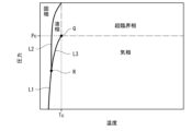
- FIG. 2 is a phase diagram showing the relationship between the phase of hydrogen and temperature-pressure.
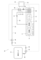
- FIG. 3 is a block diagram of the hydrogen fuel supply system of FIG.
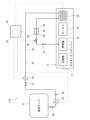
- FIG. 4 is a block diagram of a hydrogen fuel supply system according to the second embodiment.
- an aircraft refers to a device capable of moving through the air, such as a fixed-wing aircraft, a rotorcraft, or an unmanned flying object.
- FIG. 1 is a plan view of an aircraft 1 equipped with a hydrogen fuel supply system 10 according to a first embodiment.
- the aircraft 1 includes, for example, a fuselage 2, a main wing 3, a horizontal stabilizer 4, a vertical stabilizer 5, and a gas turbine engine 6.
- the fuselage 2 extends in the longitudinal direction of the aircraft 1, and defines an occupant space therein.
- the main wing 3 is connected to a middle portion of the fuselage 2 in the longitudinal direction, and protrudes from the fuselage 2 in the lateral direction of the aircraft 1.
- the horizontal stabilizer 4 protrudes from the rear of the fuselage 2 in the lateral direction of the aircraft 1.
- the vertical stabilizer 5 protrudes upward from the rear of the fuselage 2.
- the gas turbine engine 6 is connected to a pair of main wings 3.
- the hydrogen fuel supply system 10 is mounted on the fuselage 2, the main wing 3, and the gas turbine engine 6.
- the fuel tank 21 is disposed in the fuselage 2, but may be disposed in the main wing 3. That is, all or a part of the fuel tank 21 is disposed in the fuselage 2 or the main wing 3.
- Figure 2 is a phase diagram showing the relationship between hydrogen phases and temperature-pressure.
- the solid phase and gas phase are separated by the sublimation line L1
- the solid phase and liquid phase are separated by the melting line L2
- the liquid phase and gas phase are separated by the boiling line L3.
- the intersection R of the sublimation line L1, melting line L2, and boiling line L3 is called the triple point.
- Hydrogen is in a supercritical phase when the pressure is higher than the critical pressure Pc and the temperature is higher than the critical temperature Tc.
- the point of the critical pressure Pc and the critical temperature Tc is called the critical point Q.
- the critical pressure Pc is about 1.3 MPa
- the critical temperature Tc is about -240°C.
- the hydrogen fuel in the phase diagram of FIG. 2, the hydrogen fuel is prevented from changing from the liquid phase to the gas phase by crossing the boiling line L3. That is, while the hydrogen fuel is in the liquid phase, the hydrogen fuel is pressurized so that the pressure of the hydrogen fuel is equal to or higher than the critical pressure Pc, and then when the hydrogen fuel is heated and reaches a temperature equal to or higher than the critical temperature Tc, the hydrogen fuel transitions from the liquid phase to the supercritical phase.
- the liquid phase hydrogen fuel flowing from the fuel tank 21 to the fuel supply line 22 is pressurized by the pressure pump 26 to a pressure equal to or higher than the critical pressure Pc.
- the hydrogen fuel flowing from the pressure pump 26 toward the gas turbine engine 6 is heated by the heat exchanger 28 or the like and reaches a temperature equal to or higher than the critical temperature Tc, the hydrogen fuel transitions from the liquid phase to the supercritical phase. This prevents the hydrogen fuel in the fuel supply line 22 from boiling from the liquid phase to the gas phase.
- FIG. 3 is a block diagram of the hydrogen fuel supply system 10 of FIG. 1.
- the hydrogen fuel supply system 10 includes a fuel tank 21.
- the fuel tank 21 stores hydrogen fuel in a liquid phase.
- the fuel tank 21 is connected to the gas turbine engine 6 by a fuel supply line 22.
- the fuel supply line 22 extends from the fuselage 2 through the wing 3 to the gas turbine engine 6.
- the fuel supply line 22 extends from the wing 3 to the gas turbine engine 6.
- the gas turbine engine 6 includes a compressor 11, a combustor 12, and a turbine 13.
- the fuel supply line 22 is connected to the combustor 12.
- the fuel supply path 22 is provided with a feed pump 23 that sends hydrogen fuel from the fuel tank 21 to the fuel supply path 22.
- the fuel supply path 22 is provided with a shutoff valve 24 between the fuel tank 21 and the feed pump 23.
- the fuel supply path 22 is provided with a check valve 25 downstream of the feed pump 23.
- the fuel supply line 22 is provided with a pressure booster pump 26 downstream of the check valve 25.
- the pressure booster pump 26 pressurizes the hydrogen fuel in the fuel supply line 22 to a pressure equal to or greater than the hydrogen critical pressure Pc.
- the pressure booster pump 26 pressurizes liquid phase hydrogen fuel supplied from the fuel tank 21 so that the hydrogen fuel flowing through the fuel supply line 22 is at a pressure equal to or greater than the hydrogen critical pressure Pc when it reaches a control valve 30 described below.
- the hydrogen fuel is pressurized by the pressure booster pump 26 to a pressure equal to or greater than the critical pressure Pc, the hydrogen fuel is at a temperature below the critical temperature Tc.
- the fuel supply line 22 is provided with a shutoff valve 27 between the check valve 25 and the pressure booster pump 26.
- a heat exchanger 28 is provided in the fuel supply path 22 downstream of the pressure pump 26.
- the heat exchanger 28 heats the hydrogen fuel flowing through the fuel supply path 22 to a temperature equal to or higher than the critical temperature Tc of hydrogen.
- the heat exchanger 28 is thermally connected to the gas turbine engine 6. That is, the heat exchanger 28 uses the heat of the gas turbine engine 6 to heat the hydrogen fuel in the fuel supply path 22.
- the fuel supply line 22 is provided with a sensor 29 downstream of the booster pump 26.
- the fuel supply line 22 is provided with a sensor 29 downstream of the booster pump 26 and upstream of the heat exchanger 28. It is preferable that the sensor 29 is adjacent to the booster pump 26, the heat exchanger 28, or both. In this disclosure, “adjacent" means that no other fluid equipment such as a valve, pump, etc. is interposed between the two pieces of equipment.
- the sensor 29 includes a flow meter 41, a pressure gauge 42, and a thermometer 43. That is, the sensor 29 measures the flow rate, pressure, and temperature of the hydrogen fuel that has passed through the booster pump 26.
- the fuel supply path 22 is provided with a control valve 30 downstream of the sensor 29. It is preferable that the control valve 30 is adjacent to the sensor 29. The control valve 30 adjusts the flow rate of hydrogen fuel that has passed through the sensor 29.
- the fuel supply path 22 is provided with a shutoff valve 31 downstream of the control valve 30. The presence or absence and location of the shutoff valves 24, 27, and 31 are optional.
- the fuel supply passage 22 may be provided with a control valve 30 upstream of the sensor 29, or upstream and downstream of the sensor 29. In either case, it is preferable that the control valve 30 be adjacent to the sensor 29.
- the hydrogen fuel supply system 10 includes a controller 32.
- the controller 32 includes a processing circuit 33.
- the processing circuit 33 includes a processor, a system memory, and a storage memory.
- the processor is, for example, a CPU.
- the system memory is, for example, a RAM.
- the storage memory is, for example, a hard disk, a flash memory, or a combination thereof.
- a configuration in which a program stored in the storage memory is read into the system memory and executed by the processor is one example of the processing circuit 33.
- the processing circuit 33 is configured to control the booster pump 26 or the control valve 30 in response to a measurement signal from the sensor 29.
- the processing circuit 33 may be configured to control the feed pump 23.
- the processing circuit 33 may be configured to control the booster pump 26, the control valve 30, and the feed pump 23 individually or simultaneously.
- the measurement signal from the sensor 29 is, for example, the pressure or flow rate of the hydrogen fuel.
- the processing circuit 33 When the processing circuit 33 receives an engine start command, it drives the feed pump 23.
- the processing circuit 33 controls the pressure pump 26 so as to pressurize the hydrogen fuel in the fuel supply line 22 to a pressure equal to or higher than the critical pressure Pc.
- the processing circuit 33 controls the control valve 30 so that the flow rate measured by the sensor 29 becomes the target flow rate.
- the processing circuit 33 outputs an alert if the pressure measured by the sensor 29 is lower than the critical pressure Pc, or if the flow rate measured by the sensor 29 is lower than a predetermined flow rate.
- the processing circuit 33 also outputs an alert if the temperature measured by the sensor 29 is lower than the critical temperature Tc.
- the processing circuit 33 controls the pressure pump 26 so that the pressure measured by the sensor 29 becomes equal to or higher than the critical pressure Pc.
- the processing circuit 33 can feedback-control the pressure pump 26 in response to a measurement signal relating to the pressure of the hydrogen fuel measured by the sensor 29.
- the processing circuit 33 controls the control valve 30 so that the flow rate measured by the sensor 29 becomes the predetermined flow rate.
- the processing circuit 33 can control the opening degree of the control valve 30 in response to a measurement signal relating to the flow rate of hydrogen fuel measured by the sensor 29.
- the processing circuit 33 may control the amount of heat input to the liquid hydrogen per unit density in the heat exchanger 28 so that the temperature measured by the sensor 29 becomes equal to or higher than the critical temperature Tc.
- a heat shield may be provided upstream of the heat exchanger 28, and the actuator of the heat shield may be controlled to change the area that the heat shield covers the heat exchanger 28.
- the fuel supply passage 22 includes a first area A1 upstream of the heat exchanger 28 and a second area A2 provided in the gas turbine engine 6 and downstream of the heat exchanger 28.
- the first area A1 of the fuel supply passage 22 is disposed in the fuselage 2 or the wing 3.
- the second area A2 of the fuel supply passage 22 is disposed in the gas turbine engine 6.
- the first area A1 of the fuel supply passage 22 is covered with a heat insulating material. This keeps the hydrogen fuel at a low temperature from the fuel tank 21 to the heat exchanger 28.
- the second area A2 of the fuel supply passage 22 is not covered with a heat insulating material. This prevents an increase in weight in the gas turbine engine 6 and suppresses a reduction in space.
- the sensor 29 is provided downstream of the booster pump 26, so that the processing circuit 33 controls the booster pump 26 in response to the measurement signal of the hydrogen fuel pressure from the sensor 29, thereby making it possible to maintain the pressure of the hydrogen fuel within an appropriate range. This makes it possible to stabilize the operation of the engine that uses hydrogen fuel in the supercritical phase.
- control valve 30 is provided downstream of the booster pump 26 in addition to the sensor 29, the processing circuit 33 can control the control valve 30 in response to the measurement signal from the sensor 29 regarding the flow rate of hydrogen fuel, thereby keeping the flow rate of hydrogen fuel within an appropriate range. This makes it possible to stabilize the engine output.
- control valve 30 is provided downstream of the sensor 29, the flow rate of hydrogen fuel before adjustment by the control valve 30 can be measured. Also, if a control valve 30 is provided upstream of the sensor 29, the fuel supply state to the gas turbine engine 6 after adjustment by the control valve 30 can be measured.
- Second Embodiment 4 is a block diagram of a hydrogen fuel supply system 110 according to the second embodiment. Components common to the first embodiment are denoted by the same reference numerals and will not be described. As shown in FIG. 4, the hydrogen fuel supply system 110 of the second embodiment has a different arrangement of a sensor 29 compared to the hydrogen fuel supply system 10 of the first embodiment. In this embodiment, the sensor 29 is provided downstream of the pressure pump 26 and the heat exchanger 28. It is preferable that the sensor 29 is adjacent to the heat exchanger 28. Other components are similar to those of the first embodiment and will not be described.
- the control valve 30 is provided downstream of the sensor 29.
- the control valve 30 may be provided upstream of the sensor 29, or may be provided both upstream and downstream of the sensor 29. In either case, it is desirable that the control valve 30 be adjacent to the sensor 29.
- the sensor 29 since the sensor 29 is provided downstream of the heat exchanger 28, the sensor 29 can measure the pressure of the hydrogen fuel at a position close to the gas turbine engine 6.
- the processing circuit 33 controls the booster pump 26 in response to the measurement signal from the sensor 29 regarding the pressure of the hydrogen fuel, thereby making it possible to maintain the pressure of the hydrogen fuel within an appropriate range. This makes it possible to stabilize the operation of the engine that uses hydrogen fuel in the supercritical phase.
- the above embodiment has been described as an example of the technology disclosed in this application.
- the technology in this disclosure is not limited to this, and can be applied to embodiments in which modifications, substitutions, additions, omissions, etc. have been made as appropriate.
- some configurations or methods in one embodiment may be applied to other embodiments, and some configurations in an embodiment can be separated from other configurations in that embodiment and extracted as desired.
- the components described in the attached drawings and detailed description include not only components essential for solving the problem, but also components that are not essential for solving the problem, in order to illustrate the technology.
- circuits or processing circuits including general purpose processors, special purpose processors, integrated circuits, Application Specific Integrated Circuits (ASICs), Field Programmable Gate Arrays (FPGAs), conventional circuits, and/or combinations thereof, configured or programmed to perform the disclosed functions.
- ASICs Application Specific Integrated Circuits
- FPGAs Field Programmable Gate Arrays
- Processors are considered processing circuits or circuits because they include transistors and other circuitry.
- a circuit, unit, or means is hardware that performs the recited functions or hardware that is programmed to perform the recited functions.
- the hardware may be hardware disclosed herein or other known hardware that is programmed or configured to perform the recited functions. Where the hardware is a processor, which is considered a type of circuit, the circuit, means, or unit is a combination of hardware and software, and the software is used to configure the hardware and/or the processor.
- a hydrogen fuel supply system for an aircraft having an engine comprising: A fuel tank for storing hydrogen fuel in a liquid phase; a fuel supply line connecting the fuel tank to the engine; a pressure pump provided in the fuel supply passage and configured to pressurize the hydrogen fuel to a pressure equal to or higher than a critical pressure; a sensor that is provided in the fuel supply path downstream of the booster pump and that measures a pressure of the hydrogen fuel that has passed through the booster pump.
- the pressure of the hydrogen fuel can be measured by a sensor downstream of the pressure pump. This makes it possible to control the operation of the pressure pump according to the pressure of the hydrogen fuel, thereby stabilizing the operation of the engine that uses hydrogen fuel in the supercritical phase.
- the hydrogen fuel can be pressurized to a pressure equal to or higher than the critical pressure by the pressure pump, and then heated to a temperature equal to or higher than the critical temperature by the heat exchanger, so that the hydrogen fuel can be smoothly brought into the supercritical phase.
- the flow rate of hydrogen fuel supplied to the engine can be adjusted by the control valve.
- the pressure and temperature of the hydrogen fuel that has passed through the booster pump can be measured by a sensor. This makes it possible to control the operation of the booster pump according to the pressure and temperature of the hydrogen fuel downstream of the booster pump, stabilizing the operation of the engine that uses hydrogen fuel in the supercritical phase.
- the pressure and temperature of the hydrogen fuel that has passed through the booster pump and heat exchanger can be measured by sensors. This makes it possible to control the operation of the booster pump according to the pressure and temperature of the hydrogen fuel downstream of the heat exchanger, stabilizing the operation of the engine that uses supercritical hydrogen fuel.
- the senor is adjacent to the booster pump, so the pressure and temperature of the hydrogen fuel discharged by the booster pump can be measured with even greater accuracy.
- This configuration allows for more accurate measurement of the pressure and temperature of the hydrogen fuel that are directly related to at least one of the pressure pump and the heat exchanger.
- This configuration allows for more accurate measurement of the pressure and temperature of the hydrogen fuel that are directly related to at least one of the pressure pump, the heat exchanger, and the control valve.
- This configuration allows the flow rate of hydrogen fuel to be measured with high precision, and therefore allows the engine output to be controlled with high precision.
- control valve is controlled according to the flow rate measured by the sensor, making it possible to precisely adjust the flow rate of hydrogen fuel supplied to the engine.
- the aircraft comprises a fuselage, a wing connected to the fuselage, and the engine connected to the wing;
- the fuel tank is disposed in the fuselage or the main wing,
- the heat exchanger is disposed in the engine, the fuel supply passage includes a first region provided in the fuselage or the main wing and located upstream of the heat exchanger, and a second region provided in the engine and located downstream of the heat exchanger; 12.
- This configuration keeps the hydrogen fuel at a low temperature all the way to the heat exchanger, while eliminating the need for insulation around the engine, preventing weight gain and reducing the space around the engine.
Landscapes
- Engineering & Computer Science (AREA)
- Aviation & Aerospace Engineering (AREA)
- Output Control And Ontrol Of Special Type Engine (AREA)
Abstract
Description
図1は、第1実施形態に係る水素燃料供給システム10を備えた航空機1の平面図である。図1に示すように、航空機1は、例えば、胴体2、主翼3、水平尾翼4、垂直尾翼5、及び、ガスタービンエンジン6を備える。胴体2は、航空機1の前後方向に延び、内部に乗員空間が画定されている。主翼3は、胴体2の前後方向の中間部に接続され、胴体2から航空機1の左右方向にそれぞれ突出している。水平尾翼4は、胴体2の後部から航空機1の左右方向にそれぞれ突出している。垂直尾翼5は、胴体2の後部から上方に突出している。ガスタービンエンジン6は、一対の主翼3にそれぞれ接続されている。胴体2、主翼3及びガスタービンエンジン6には、水素燃料供給システム10が搭載されている。燃料タンク21は、胴体2に配置されているが、主翼3に配置されてもよい。即ち、燃料タンク21の全部又は一部は、胴体2又は主翼3に配置される。
また、図4は、第2実施形態に係る水素燃料供給システム110のブロック図である。なお、第1実施形態と共通する構成については同一符号を付して説明を省略する。図4に示すように、第2実施形態の水素燃料供給システム110では、第1実施形態の水素燃料供給システム10に比べてセンサ29の配置が異なる。本実施形態では、加圧ポンプ26及び熱交換器28の下流にセンサ29が設けられている。センサ29は、熱交換器28に隣接していることが望ましい。なお、他の構成は前述した第1実施形態と同様であるため説明を省略する。
エンジンを備えた航空機の水素燃料供給システムであって、
水素燃料を液相で貯留する燃料タンクと、
前記燃料タンクを前記エンジンに接続する燃料供給路と、
前記燃料供給路に設けられ、前記水素燃料を臨界圧力以上の圧力に加圧する加圧ポンプと、
前記燃料供給路において前記加圧ポンプよりも下流に設けられ、前記加圧ポンプを通過した水素燃料の圧力を測定するセンサと、を備える、水素燃料供給システム。
前記燃料供給路において前記加圧ポンプよりも下流に設けられ、前記水素燃料を臨界温度以上の温度に加熱する熱交換器を更に備える、項目1に記載の水素燃料供給システム。
前記燃料供給路において前記加圧ポンプよりも下流に設けられ、前記加圧ポンプを通過した水素燃料の流量を制御する制御弁を更に備える、項目1又は2に記載の水素燃料供給システム。
前記センサは、前記燃料供給路において前記熱交換器よりも上流に設けられ、前記加圧ポンプを通過した水素燃料の圧力及び温度を測定する、項目2又は3に記載の水素燃料供給システム。
前記センサは、前記燃料供給路において前記熱交換器よりも下流に設けられ、前記熱交換器を通過した水素燃料の圧力及び温度を測定する、項目2又は3に記載の水素燃料供給システム。
前記センサは、前記加圧ポンプに隣接している、項目1乃至5のいずれか1項に記載の水素燃料供給システム。
前記センサは、前記加圧ポンプ、及び、前記熱交換器の少なくとも1つに隣接している、項目1乃至5のいずれか1項に記載の水素燃料供給システム。
前記センサは、前記加圧ポンプ、前記熱交換器、及び、前記制御弁の少なくとも1つに隣接している、項目3乃至5のいずれか1項に記載の水素燃料供給システム。
前記センサは、前記加圧ポンプを通過した水素燃料の流量を更に測定する、項目1乃至8のいずれか1項に記載の水素燃料供給システム。
前記センサの圧力の測定信号に応じて前記加圧ポンプを制御するように構成された処理回路を更に備える、項目1乃至9のいずれか1項に記載の水素燃料供給システム。
前記センサの流量の測定信号に応じて前記制御弁の開度を制御するように構成された処理回路を更に備える、項目9に記載の水素燃料供給システム。
前記航空機は、胴体と、前記胴体に接続された主翼と、前記主翼に接続された前記エンジンとを備え、
前記燃料タンクは、前記胴体又は前記主翼に配置され、
前記熱交換器は、前記エンジンに配置され、
前記燃料供給路は、前記胴体又は前記主翼に設けられて前記熱交換器の上流にある第1領域と、前記エンジンに設けられて前記熱交換器の下流にある第2領域と、を含み、
前記第1領域は、断熱材に被覆されており、前記第2領域は、断熱材に被覆されていない、項目1乃至11のいずれか1項に記載の水素燃料供給システム。
2 胴体
3 主翼
6 ガスタービンエンジン
10 水素燃料供給システム
21 燃料タンク
22 燃料供給路
26 加圧ポンプ
28 熱交換器
29 センサ
30 制御弁
33 処理回路
41 流量計
42 圧力計
43 温度計
A1 第1領域
A2 第2領域
Claims (12)
- エンジンを備えた航空機の水素燃料供給システムであって、
水素燃料を液相で貯留する燃料タンクと、
前記燃料タンクを前記エンジンに接続する燃料供給路と、
前記燃料供給路に設けられ、前記水素燃料を臨界圧力以上の圧力に加圧する加圧ポンプと、
前記燃料供給路において前記加圧ポンプよりも下流に設けられ、前記加圧ポンプを通過した水素燃料の圧力を測定するセンサと、を備える、水素燃料供給システム。 - 前記燃料供給路において前記加圧ポンプよりも下流に設けられ、前記水素燃料を臨界温度以上の温度に加熱する熱交換器を更に備える、請求項1に記載の水素燃料供給システム。
- 前記燃料供給路において前記加圧ポンプよりも下流に設けられ、前記加圧ポンプを通過した水素燃料の流量を制御する制御弁を更に備える、請求項1又は2に記載の水素燃料供給システム。
- 前記センサは、前記燃料供給路において前記熱交換器よりも上流に設けられ、前記加圧ポンプを通過した水素燃料の圧力及び温度を測定する、請求項2又は3に記載の水素燃料供給システム。
- 前記センサは、前記燃料供給路において前記熱交換器よりも下流に設けられ、前記熱交換器を通過した水素燃料の圧力及び温度を測定する、請求項2又は3に記載の水素燃料供給システム。
- 前記センサは、前記加圧ポンプに隣接している、請求項1乃至5のいずれか1項に記載の水素燃料供給システム。
- 前記センサは、前記加圧ポンプ、及び、前記熱交換器の少なくとも1つに隣接している、請求項1乃至5のいずれか1項に記載の水素燃料供給システム。
- 前記センサは、前記加圧ポンプ、前記熱交換器、及び、前記制御弁の少なくとも1つに隣接している、請求項3乃至5のいずれか1項に記載の水素燃料供給システム。
- 前記センサは、前記加圧ポンプを通過した水素燃料の流量を更に測定する、請求項1乃至8のいずれか1項に記載の水素燃料供給システム。
- 前記センサの圧力の測定信号に応じて前記加圧ポンプを制御するように構成された処理回路を更に備える、請求項1乃至9のいずれか1項に記載の水素燃料供給システム。
- 前記センサの流量の測定信号に応じて前記制御弁の開度を制御するように構成された処理回路を更に備える、請求項9に記載の水素燃料供給システム。
- 前記航空機は、胴体と、前記胴体に接続された主翼と、前記主翼に接続された前記エンジンとを備え、
前記燃料タンクは、前記胴体又は前記主翼に配置され、
前記熱交換器は、前記エンジンに配置され、
前記燃料供給路は、前記胴体又は前記主翼に設けられて前記熱交換器の上流にある第1領域と、前記エンジンに設けられて前記熱交換器の下流にある第2領域と、を含み、
前記第1領域は、断熱材に被覆されており、前記第2領域は、断熱材に被覆されていない、請求項1乃至11のいずれか1項に記載の水素燃料供給システム。
Priority Applications (1)
| Application Number | Priority Date | Filing Date | Title |
|---|---|---|---|
| EP24831837.0A EP4737327A1 (en) | 2023-06-30 | 2024-06-21 | Hydrogen fuel supply system |
Applications Claiming Priority (2)
| Application Number | Priority Date | Filing Date | Title |
|---|---|---|---|
| JP2023-107957 | 2023-06-30 | ||
| JP2023107957A JP2025006910A (ja) | 2023-06-30 | 2023-06-30 | 水素燃料供給システム |
Publications (1)
| Publication Number | Publication Date |
|---|---|
| WO2025004976A1 true WO2025004976A1 (ja) | 2025-01-02 |
Family
ID=93938486
Family Applications (1)
| Application Number | Title | Priority Date | Filing Date |
|---|---|---|---|
| PCT/JP2024/022488 Ceased WO2025004976A1 (ja) | 2023-06-30 | 2024-06-21 | 水素燃料供給システム |
Country Status (3)
| Country | Link |
|---|---|
| EP (1) | EP4737327A1 (ja) |
| JP (1) | JP2025006910A (ja) |
| WO (1) | WO2025004976A1 (ja) |
Citations (1)
| Publication number | Priority date | Publication date | Assignee | Title |
|---|---|---|---|---|
| US20220145801A1 (en) | 2020-11-06 | 2022-05-12 | General Electric Company | Hydrogen fuel system |
-
2023
- 2023-06-30 JP JP2023107957A patent/JP2025006910A/ja active Pending
-
2024
- 2024-06-21 EP EP24831837.0A patent/EP4737327A1/en active Pending
- 2024-06-21 WO PCT/JP2024/022488 patent/WO2025004976A1/ja not_active Ceased
Patent Citations (1)
| Publication number | Priority date | Publication date | Assignee | Title |
|---|---|---|---|---|
| US20220145801A1 (en) | 2020-11-06 | 2022-05-12 | General Electric Company | Hydrogen fuel system |
Also Published As
| Publication number | Publication date |
|---|---|
| EP4737327A1 (en) | 2026-05-06 |
| JP2025006910A (ja) | 2025-01-17 |
Similar Documents
| Publication | Publication Date | Title |
|---|---|---|
| US7959109B2 (en) | Dual valve apparatus for aircraft engine ice protection and related methods | |
| US7784487B2 (en) | Fuel metering valve assembly including thermal compensation mechanism | |
| JP5550552B2 (ja) | コンプレッサにアクティブ安定化を施すようにしたガスタービンの制御 | |
| US20180057171A1 (en) | Advanced method and aircraft for pre-cooling an environmental control system using a three wheel turbo-machine | |
| US10974835B2 (en) | Bleed air temperature and flow control system | |
| CN108027622A (zh) | 用于调节调整单元的方法和具有这种调整单元的消耗量测量装置 | |
| US20180090353A1 (en) | Method of achieving improved transient response in apparatus for controlling flow and system for accomplishing same | |
| US11371436B2 (en) | Method and system for regulating oil flow to an engine | |
| EP3543136B1 (en) | Synthesized low-pressure bleed air scheme for aircraft bleed air network | |
| WO2024210030A1 (ja) | 水素航空機 | |
| CN110455859A (zh) | 基于氧乙炔平台的发汗冷却测试系统及测试方法 | |
| US20130013145A1 (en) | Decoupling control architecture for pressure and flow controls in series | |
| JP2025006910A (ja) | 水素燃料供給システム | |
| US3025670A (en) | Method and apparatus for detecting, measuring and controlling the temperature of gas turbine engines | |
| JP2887938B2 (ja) | 航空エンジン試験装置 | |
| CN109983217A (zh) | 用于调节气体流量的装置和方法 | |
| US7950987B2 (en) | Aircraft cabin pressure control system and method that improves cabin pressurization during take-off | |
| US20120279698A1 (en) | Temperature control setpoint offset for ram air minimization | |
| US11168805B2 (en) | Thermally actuated flow control valve | |
| US2484850A (en) | Means for cooling and pressurizing aircraft cabins | |
| US11933182B2 (en) | Multi-channel multi-range transducer | |
| WO2024210029A1 (ja) | 水素燃料供給システム及び航空機 | |
| JPH087109B2 (ja) | 吹出式風洞の圧力制御装置 | |
| JP2587875B2 (ja) | 航空機用空気調和装置 | |
| US12331767B2 (en) | Adjustable flow control systems |
Legal Events
| Date | Code | Title | Description |
|---|---|---|---|
| 121 | Ep: the epo has been informed by wipo that ep was designated in this application |
Ref document number: 24831837 Country of ref document: EP Kind code of ref document: A1 |
|
| WWE | Wipo information: entry into national phase |
Ref document number: 2024831837 Country of ref document: EP |
|
| NENP | Non-entry into the national phase |
Ref country code: DE |
|
| ENP | Entry into the national phase |
Ref document number: 2024831837 Country of ref document: EP Effective date: 20260130 |
|
| ENP | Entry into the national phase |
Ref document number: 2024831837 Country of ref document: EP Effective date: 20260130 |
|
| WWP | Wipo information: published in national office |
Ref document number: 2024831837 Country of ref document: EP |