WO2025004750A1 - ハロゲン化物固体電解質の製造方法、ハロゲン化物固体電解質、正極材料、および電池 - Google Patents
ハロゲン化物固体電解質の製造方法、ハロゲン化物固体電解質、正極材料、および電池 Download PDFInfo
- Publication number
- WO2025004750A1 WO2025004750A1 PCT/JP2024/020791 JP2024020791W WO2025004750A1 WO 2025004750 A1 WO2025004750 A1 WO 2025004750A1 JP 2024020791 W JP2024020791 W JP 2024020791W WO 2025004750 A1 WO2025004750 A1 WO 2025004750A1
- Authority
- WO
- WIPO (PCT)
- Prior art keywords
- halide
- solid electrolyte
- composition
- halogen
- halide solid
- Prior art date
- Legal status (The legal status is an assumption and is not a legal conclusion. Google has not performed a legal analysis and makes no representation as to the accuracy of the status listed.)
- Ceased
Links
Images


Classifications
-
- Y—GENERAL TAGGING OF NEW TECHNOLOGICAL DEVELOPMENTS; GENERAL TAGGING OF CROSS-SECTIONAL TECHNOLOGIES SPANNING OVER SEVERAL SECTIONS OF THE IPC; TECHNICAL SUBJECTS COVERED BY FORMER USPC CROSS-REFERENCE ART COLLECTIONS [XRACs] AND DIGESTS
- Y02—TECHNOLOGIES OR APPLICATIONS FOR MITIGATION OR ADAPTATION AGAINST CLIMATE CHANGE
- Y02E—REDUCTION OF GREENHOUSE GAS [GHG] EMISSIONS, RELATED TO ENERGY GENERATION, TRANSMISSION OR DISTRIBUTION
- Y02E60/00—Enabling technologies; Technologies with a potential or indirect contribution to GHG emissions mitigation
- Y02E60/10—Energy storage using batteries
Definitions
- the present disclosure relates to a method for producing a halide solid electrolyte, a halide solid electrolyte, a positive electrode material, and a battery.
- Patent Document 1 discloses a halide-based solid electrolyte material.
- Patent Document 2 discloses a halide-based solid electrolyte material as a solid electrolyte material that coats the surface of a positive electrode active material.
- the purpose of this disclosure is to provide a new manufacturing method that can stably synthesize a halide solid electrolyte having a desired composition.
- the method for producing a halide solid electrolyte according to the present disclosure includes the steps of: (A) converting a first composition comprising Li, Ti, and O into a first halide comprising Li, Ti, and X1; (B) synthesizing a halide solid electrolyte containing Li, Ti, M, X1, and X2 using the first halide obtained in (A) and a second halide containing Li, M, and X2; Includes.
- the M is at least one element selected from the group consisting of metal elements (excluding Li) and metalloid elements
- X1 is at least one selected from the group consisting of F, Cl, Br, and I
- X2 is at least one selected from the group consisting of F, Cl, Br, and I.
- This disclosure provides a new manufacturing method that can stably synthesize a halide solid electrolyte having a desired composition.
- FIG. 1 is a flow chart showing an example of a method for producing a halide solid electrolyte according to the first embodiment.
- FIG. 2 is a flow chart showing an example of a method for producing a halide solid electrolyte according to the second embodiment.
- FIG. 3 is a flow chart showing a modified example of the method for producing a halide solid electrolyte according to the second embodiment.
- FIG. 4 is a flow chart showing an example of a method for producing a halide solid electrolyte according to the third embodiment.
- FIG. 5 shows a cross-sectional view of a battery 1000 according to a fourth embodiment.
- FIG. 1 is a flow chart showing an example of a method for producing a halide solid electrolyte according to the first embodiment.
- FIG. 2 is a flow chart showing an example of a method for producing a halide solid electrolyte according to the second embodiment.
- FIG. 3 is a flow chart showing a modified example of the method for producing
- FIG. 6A is a graph showing an X-ray diffraction pattern of the halide solid electrolyte after the heat treatment and before the pulverization treatment in the production method of Example 1.
- FIG. 6B is a graph showing X-ray diffraction patterns of the pulverized halide solid electrolyte obtained in Example 1 and the halide solid electrolyte obtained in Comparative Example 1.
- the manufacturing method according to the first embodiment includes the steps of: (A) converting a first composition comprising Li, Ti, and O into a first halide comprising Li, Ti, and X1; (B) synthesizing a halide solid electrolyte containing Li, Ti, M, X1, and X2 using the first halide obtained in (A) and a second halide containing Li, M, and X2;
- M is at least one element selected from the group consisting of metal elements (excluding Li) and metalloid elements
- X1 is at least one element selected from the group consisting of F, Cl, Br, and I
- X2 is at least one element selected from the group consisting of F, Cl, Br, and I.
- “Semi-metallic elements” are B, Si, Ge, As, Sb, and Te.
- Metallic elements are all elements in groups 1 to 12 of the periodic table (except hydrogen) and all elements in groups 13 to 16 of the periodic table (except B, Si, Ge, As, Sb, Te, C, N, P, O, S, and Se).
- metalic elements are a group of elements that can become cations when they form inorganic compounds with halogen compounds.
- the manufacturing method according to the first embodiment makes it possible to stably synthesize a halide solid electrolyte having a desired composition. The reasons for this are explained in more detail below.
- titanium halide e.g., TiX4
- TiX4 titanium halide
- the produced halide solid electrolyte may have compositional fluctuations (i.e., compositional deviations) and changes in quality (e.g., inclusion of moisture, etc.).
- the first composition containing Li, Ti, and O can be used as the Ti source.
- the manufacturing method according to the first embodiment in the synthesis of the halide solid electrolyte containing Ti, it is not necessary to use the unstable titanium halide as a raw material, and titanium halide is not easily generated in the synthesis process. Therefore, the manufacturing method according to the first embodiment is less likely to cause the above-mentioned compositional fluctuation and deterioration in the manufactured halide solid electrolyte, and can reproducibly and stably synthesize, for example, a Ti-containing halide solid electrolyte having excellent properties such as ionic conductivity. That is, the manufacturing method according to the first embodiment can stably synthesize a halide solid electrolyte having a target composition.
- the above (A) may include converting a second composition containing Li, M, and O into the above second halide.
- a halide solid electrolyte is synthesized using the first halide and the second halide obtained in the above (A).
- the halogenation treatment for converting the first composition and the second composition into the first halide and the second halide, respectively may be carried out at a temperature of, for example, 150°C or higher.
- the first composition and the second composition can be sufficiently halogenated.
- the temperature during the halogenation treatment may be, for example, 600°C or lower.
- the atmosphere for the halogenation treatment may be, for example, air, a nitrogen atmosphere, a reducing atmosphere, or any other atmosphere suitable for the halogen-containing material used.
- the conversion of the first composition to the first halide may be carried out, for example, by heat-treating a thermally decomposable first halogen-containing material.
- the conversion of the second composition to the second halide may be carried out, for example, by heat-treating a thermally decomposable second halogen-containing material.
- the first halogen-containing material and the second halogen-containing material may be the same substance or different substances.
- the halogenation of the first composition and the second composition can be efficiently performed in a short time. Furthermore, since the halogenation can be performed by a short heat treatment, it is possible to obtain a solid electrolyte with homogeneous and excellent properties while reducing reaction residues such as oxides. Furthermore, by heat treating the first halogen-containing material and the second halogen-containing material, which have thermal decomposition properties, the first composition is converted into the first halide and the second composition is converted into the second halide, respectively. Therefore, the reactivity (halogenation property) of the first composition and the second composition is good, and the productivity is also excellent.
- the temperature of the halogenation reaction of the first composition and the progress of the reaction can be controlled according to the thermal decomposition temperature of the substance selected as the first halogen-containing material.
- the temperature of the halogenation reaction of the second composition and the progress of the reaction can be controlled according to the thermal decomposition temperature of the substance selected as the second halogen-containing material. Therefore, a process suitable for various halide solid electrolytes can be performed.
- the above (A) is (A-1) mixing a first composition with a first halogen-containing substance; (A-2) converting the first composition into a first halide by heat-treating the mixture containing the first composition and the first halogen-containing substance obtained in (A-1) above; may also include
- a heat treatment for halogenation can be carried out on the homogeneous mixture of the first composition and the first halogen-containing substance.
- the contact area between the first composition and the first halogen-containing substance can be increased. Therefore, the halogenation of the first composition can be promoted homogeneously. As a result, a halide solid electrolyte that is homogeneous and has excellent properties can be obtained.
- the above (A) is (A-3) mixing the second composition with a second halogen-containing material; (A-4) converting the second composition into a second halide by heat treating the mixture containing the second composition and the second halogen-containing substance obtained in (A-3) above; may also include
- a heat treatment for halogenation can be carried out on the homogeneous mixture of the second composition and the second halogen-containing substance.
- the contact area between the second composition and the second halogen-containing substance can be increased. Therefore, the halogenation of the second composition can be promoted homogeneously. Therefore, a halide solid electrolyte that is homogeneous and has excellent properties can be obtained.
- FIG. 1 is a flow chart showing an example of a method for producing a halide solid electrolyte according to the first embodiment.
- the production method according to the first embodiment an example of a production method in which the above (A-1), (A-2), (A-3), and (A-4) are implemented will be described.
- the first composition and the first halogen-containing substance are mixed (S11) as a step corresponding to the above (A-1), and then the second composition and the second halogen-containing substance are mixed (S12) as a step corresponding to the above (A-3).
- the first composition contains Li, Ti, and O.
- the second composition contains Li, M, and O.
- the first halogen-containing substance and the second halogen-containing substance are thermally decomposable.
- the first composition is converted into the first halide by heat-treating the first mixture containing the first composition and the first halogen-containing substance obtained in the above (A-1) (S13).
- the second composition is converted into the second halide by heat-treating the second mixture containing the second composition and the second halogen-containing substance obtained in the above (A-3) (S14).
- the first halide and the second halide are used to synthesize a halide solid electrolyte containing Li, Ti, M, X1, and X2 (S15).
- the first composition, the second composition, the first halogen-containing substance, and the second halogen-containing substance will be specifically described. Furthermore, the steps corresponding to the above (A-1), (A-2), (A-3), and (A-4), as well as the above (B), will be specifically described.
- the first composition includes Li, Ti, and O.
- the first composition includes, for example, lithium oxide (e.g., Li2O ) and titanium oxide (e.g., TiO2 ).
- the first composition may include a composite oxide containing Li and Ti, such as Li2TiO3 .
- the first composition may have a composition that produces a complex fluoride containing Li and Ti, for example.
- the composition ratio of metal oxides, hydroxides, carbonates, etc., of the components that make up the first composition may be adjusted so that the molar ratio of Li to Ti is a desired ratio.
- the composition ratio of the first composition may be adjusted so that a complex fluoride containing Li and Ti is produced, for example.
- Titanium oxide e.g., TiO2
- the first composition may be a composition that produces a complex fluoride containing Li and Ti.
- it can be converted into a first halide represented by Li2TiF6 by halogenation treatment. This makes it possible to suppress the production of TiF4 even when TiO2 is used as the starting material.
- the crystal system of titanium oxide is not particularly limited, and both rutile and anatase can be used.
- each component constituting the first composition such as Li2O and TiO2
- Each component constituting the first composition may be, for example, particulate. This makes it easier for halogenation (i.e., replacement of halogen elements with oxygen elements) from the particle surface of the components constituting the first composition and solid-phase reaction in the components constituting the first composition to occur simultaneously. Therefore, a homogeneous first halide can be synthesized in a short time while reducing reaction residues such as oxides.
- the reactivity such as halogenation and solid-phase reactivity is good, so that excellent productivity can be realized.
- Each component constituting the first composition may have an average particle size of, for example, 0.5 ⁇ m or more and 20 ⁇ m or less.
- the average particle size of each component constituting the first composition is not limited to the above range, and any particle size and shape may be appropriately selected from the viewpoint of the halogenation reaction and the solid-phase reaction.
- the smaller the particle size of each component constituting the first composition the lower the temperature for conversion to the first halide can be.
- the average particle size of each component constituting the first composition is the median size of each component, and means the particle size (d50) corresponding to 50% cumulative volume, determined from the particle size distribution measured on a volume basis by a laser diffraction scattering method.
- the second composition comprises Li, M, and O.
- the second composition includes, for example, lithium oxide (e.g., Li2O ) and an oxide of M.
- the second composition may include, for example, a composite oxide including Li and M, such as a composite oxide including Li and Al.
- M may be at least one selected from the group consisting of Al, Y, Ga, Dy, Ho, Er, Tm, and Yb. M may be at least one selected from the group consisting of Al and Y.
- M may contain Al. By including Al in M, a halide solid electrolyte having high ionic conductivity can be obtained.
- M may be Al.
- the second composition may be, for example, a composition that produces a complex fluoride containing Li and M.
- the composition ratio of metal oxides, hydroxides, or carbonates may be adjusted for the components constituting the second composition, for example, so that the molar ratio of Li to M is a desired ratio.
- the composition ratio of the second composition may be adjusted, for example, so that a complex fluoride containing Li and Al is produced.
- a second halide represented by, for example, Li 3 AlF 6 by halogenation treatment.
- This makes it possible to suppress the generation of unstable precipitated phases such as titanium halides (for example, TiX 4 ) that are prone to problems of evaporation and deliquescence in the halide solid electrolyte. Therefore, a halide solid electrolyte with excellent ionic conductivity and stability can be obtained.
- each component constituting the second composition such as Li2O and Al2O3
- Each component constituting the second composition may be, for example, particulate. This makes it easier for halogenation (i.e., replacement of halogen elements with oxygen elements) from the particle surface of the component constituting the second composition and solid-phase reaction in the component constituting the second composition to occur simultaneously. Therefore, a homogeneous second halide can be synthesized in a short time while reducing reaction residues such as oxides.
- the reactivity such as halogenation and solid-phase reactivity is good, so that excellent productivity can be realized.
- Each component constituting the second composition may have an average particle size of, for example, 0.5 ⁇ m or more and 20 ⁇ m or less.
- the average particle size of each component constituting the second composition is not limited to the above range, and any particle size and shape may be appropriately selected from the viewpoint of the halogenation reaction and solid-phase reaction.
- the smaller the particle size of each component constituting the second composition the lower the temperature for conversion to the second halide can be.
- the first halogen-containing material and the second halogen-containing material have thermal decomposition properties.
- a fluorine-containing material that serves as a fluorine source is used as the first halogen-containing material.
- the second halide contains F as the halogen element X2
- a fluorine-containing material that serves as a fluorine source is used as the second halogen-containing material.
- halogen-containing substance the first halogen-containing substance and the second halogen-containing substance may be collectively referred to simply as "halogen-containing substance.”
- halogen element X1 and the halogen element X2 may be collectively referred to simply as “halogen element X.”
- the thermal decomposition onset temperature of the halogen-containing material used may be, for example, 100°C or higher and 600°C or lower.
- the halogen-containing material has stability in handling such as storage and mixing, and the obtained halide solid electrolyte can be prevented from becoming too hard.
- the halogen element X may contain F or may be F. This makes it possible to obtain a halide solid electrolyte that is highly stable (e.g., has excellent electrochemical stability and heat resistance) and has high ionic conductivity.
- the halogen-containing material may be, for example, particulate. This makes it easier for the halogen-containing material to thermally decompose. Therefore, by using a particulate halogen-containing material, the components constituting the first composition and the second composition can be halogenated efficiently, and the halogen-containing material is less likely to remain in the finally obtained halide solid electrolyte. In addition, by using a particulate halogen-containing material, the amount of halogen can be precisely controlled. Therefore, it becomes easier to synthesize the desired halide solid electrolyte.
- halogen-containing material can be used in the amount necessary for halogenating the components constituting the first composition and the second composition, excess halogen gas emissions can be suppressed. This reduces the burden on the environment and also reduces the impact on corrosion of furnace materials, etc.
- the halogen-containing material may have, for example, an average particle size of 0.5 ⁇ m or more and 500 ⁇ m or less, an average particle size of 0.5 ⁇ m or more and 150 ⁇ m or less, or an average particle size of 0.5 ⁇ m or more and 100 ⁇ m or less.
- the halogen-containing material may have any particle size and shape.
- the average particle size of the halogen-containing material may be larger than the average particle size of the components constituting the first composition and the second composition. This results in a state in which the surface area of the components constituting the first composition and the second composition is larger than that of the halogen-containing material, that is, the surface exposed area (i.e., the exposed area) of the components constituting the first composition and the second composition is large. Therefore, halogenation is likely to proceed from the particle surface of the components constituting the first composition and the second composition, so that a homogeneous halide can be obtained.
- the average particle size of the halogen-containing material may be 5 ⁇ m or more and 100 ⁇ m or less, 5 ⁇ m or more and 20 ⁇ m or less, or 50 ⁇ m or more and 100 ⁇ m or less.
- the average particle size of the halogen-containing material can be appropriately adjusted taking into account the temperature or reactivity of the halogenation. For example, by increasing the average particle size of the halogen-containing material, the heat treatment temperature for the halogenation treatment becomes higher.
- the halogen-containing material may contain an ammonium salt.
- the ammonium salt starts to thermally decompose at a relatively low temperature (for example, about 150°C). Therefore, the ammonium salt is unlikely to remain as an unnecessary inorganic component in the finally obtained halide solid electrolyte, and can be thermally decomposed at a low temperature to halogenate the components constituting the first composition and the second composition. Therefore, by using an ammonium salt as the halogen-containing material, it is possible to suppress the remaining of unnecessary inorganic components derived from the halogen-containing material in the finally obtained halide solid electrolyte. Furthermore, the energy saving of the synthesis is achieved, and the temperature rise and fall time is also reduced, so that the productivity is improved. In addition, since the synthesis can be performed at a low temperature, the durability of the furnace material is improved, and the running costs and replacement frequency of the synthesis components are also significantly reduced. Only an ammonium salt may be used as the halogen-containing material.
- the ammonium salt may contain NH 4 F.
- NH 4 F is a highly decomposable fluorine source and can effectively act on the halogenation of the components constituting the first composition and the second composition. Therefore, NH 4 F can fluorinate the components constituting the first composition and the second composition while being thermally decomposed at a low temperature (e.g., about 150° C.) and at a high decomposition rate, without remaining in the solid electrolyte.
- ammonium salts of other halogen elements such as NH 4 Cl and NH 4 Br, are also thermally decomposable and can be used as halogen sources in the same manner.
- the halogen-containing material may include a resin.
- a resin as the halogen-containing material, the halogen-containing material can halogenate the components constituting the first composition and the second composition while being thermally decomposed at a relatively high temperature (e.g., about 450°C or higher and 600°C or lower). Therefore, the method including a resin as the halogen-containing material is suitable when it is desired to carry out the halogenation and solid-phase reaction at a relatively high temperature (e.g., about 450°C or higher and 600°C or lower).
- a resin used as the halogen-containing material is a fluororesin.
- a fluororesin for example, polytetrafluoroethylene (PTFE) and polyvinylidene fluoride (PVDF) can be used.
- a fluororesin such as PTFE can halogenate the components constituting the first composition and the second composition while being thermally decomposed at a relatively high temperature (e.g., about 450°C or higher and 600°C or lower). Therefore, a method including a fluororesin as a halogen-containing material is suitable when it is desired to carry out halogenation and solid-state reaction at a relatively high temperature (e.g., about 450°C or higher and 600°C or lower).
- the halogen-containing material may contain, for example, a substance that does not substantially include inorganic components resulting from thermal decomposition by the heat treatment in (A) above, except for halogen elements, in the halide solid electrolyte to be produced.
- the halogen-containing material used in the halogenation treatment is required to replace the oxygen elements of the components constituting the first composition and the second composition with halogen elements, while not mixing other components as inorganic residues into the halide solid electrolyte finally obtained by thermal decomposition by the heat treatment.
- the halogen-containing material does not substantially include inorganic components
- the content ratio of inorganic components in the entire halogen-containing material is 0.5 mass % or less.
- the halogen-containing material may contain multiple types of halogen-containing compounds.
- both ammonium salt and fluororesin can be used as the halogen-containing material. This allows the temperature range in which the halogen-containing material acts as a halogen source to be widely controlled, so that the conversion of the components constituting the first composition and the second composition to halides and the solid-phase reaction temperature can be controlled over a wide range. This makes it easy to obtain the desired halide solid electrolyte.
- the amount of the halogen-containing material used is not particularly limited, so long as it is an amount sufficient to halogenate the entire amount of the compound to be halogenated.
- the molar amount of the halogen-containing material for stoichiometrically halogenating the entire compound in the reaction to halogenate the compound to be halogenated i.e., a stoichiometrically equivalent molar amount, in other words, a molar amount required to completely replace the anion of the compound to be halogenated with a halogen anion such as F
- the amount of the halogen-containing material may be, for example, 103% or more and 150% or less, 103% or more and 130% or less, or 103% or more and 110% or less.
- the powders of the components constituting the first composition and the first halogen-containing substance are mixed in a desired ratio.
- these powders are mixed in a dry manner so as to be uniform.
- they may be mixed uniformly by repeatedly mixing with a spatula, or they may be mixed using a dry mixing device such as a mortar and pestle, a mortar grinder, or a V-blender. They may also be mixed using a medium such as zirconia balls. Any mixing means may be used as long as these powders can be mixed uniformly.
- the uniformity can be evaluated using, for example, energy dispersive X-ray spectroscopy (EDS) or an electron probe microanalyzer (EPMA). For example, the uniformity can be confirmed by observing a composition mapping image.
- EDS energy dispersive X-ray spectroscopy
- EPMA electron probe microanalyzer
- a general electric furnace may be used for the heat treatment.
- the atmosphere for the heat treatment may be selected as necessary, and the heat treatment may be performed in air, in an inert gas atmosphere (e.g., nitrogen gas or argon gas), or in a reducing gas (e.g., hydrogen or carbon dioxide).
- the synthesized halide is usually obtained as a powder, but when heat treated at or above its melting point, it may be obtained as a molten body, a sintered body, or a block-shaped mass in which the powder has solidified.
- the above-mentioned homogeneously mixed mixture is placed in, for example, an alumina heat-resistant container (sheath), and the mixture is fired in a firing furnace in any atmosphere.
- a firing furnace for example, an inert gas such as nitrogen gas is flowed into the furnace, and gases generated during halogenation (e.g., ammonium, hydrogen chloride, carbon dioxide, etc.) are discharged while the mixture is heat-treated in the atmospheric furnace at a temperature of, for example, 150°C or higher and 600°C or lower for, for example, 1 hour or higher and 40 hours or lower, to synthesize a halide solid electrolyte.
- gases generated during halogenation e.g., ammonium, hydrogen chloride, carbon dioxide, etc.
- the inert gas should be introduced into the furnace so that it does not directly hit the sheath containing the mixture.
- air may be introduced into the furnace.
- a plate larger than the gas inlet is placed between the gas inlet and the sheath.
- the plate may be thick enough that it is not damaged by the gas flow or handling. For example, it is better to partially shield it by leaning a plate such as an alumina plate against it. By shielding the space between the gas inlet and the sheath in this way, the gas will go around the shielding plate before coming into contact with the sheath.
- the gas inlet should be installed on the bottom side of the furnace, and the exhaust port on the top side (for example, on the ceiling side or above the side wall). This allows the reaction gas to be smoothly discharged outside the furnace by riding on the convection currents (from bottom to top) inside the furnace, reducing the amount of unwanted residual components that get mixed into the halide solid electrolyte.
- the gas to be introduced may be heated before being introduced into the furnace. This makes it possible to prevent the temperature distribution in the sheath from becoming uneven. This allows the synthesis reaction of the first halide to be carried out uniformly, resulting in a more homogeneous halide solid electrolyte.
- the heat treatment temperature is, for example, 150°C or more and 600°C or less, as described above, or may be 250°C or more and 600°C or less, or 250°C or more and 550°C or less.
- the heat treatment time is, for example, 1 hour or more and 40 hours or less, as described above. When the heat treatment temperature is lowered, sintering does not progress, and a halide with soft particles can be obtained. As a result, a dense green compact (a solid electrolyte with good ionic conductivity) can be obtained.
- the heat treatment temperature and heat treatment time can be determined arbitrarily, taking into consideration the temperature required for synthesis of the halide solid electrolyte, the time required for synthesis, and the time required for exhausting the reaction gas.
- the furnace used for the heat treatment can be a known firing furnace (for example, an electric furnace) or an atmospheric firing furnace. Note that in order to remove the air and moisture between the particles deep inside the sheath and completely replace it with an inert gas, a vacuum replacement can be performed before the inert gas is flowed. This can reduce the effects of reactive components and moisture contained in the air. The vacuum replacement can be performed repeatedly.
- the temperature distribution within the sheath during heat treatment may be within the temperature distribution range of a commonly used firing furnace, for example, 30°C. Note that the temperature distribution within the sheath referred to here is the difference between the maximum and minimum temperatures within the sheath.
- the mixture of the first composition and the first halogen-containing material may be placed in a sheath, and if necessary, a lid (e.g., an alumina lid) may be placed on the sheath to prevent dust and foreign objects from falling, and then the heat treatment may be performed.
- a lid e.g., an alumina lid
- the heat treatment in the manufacturing method according to the first embodiment has very good productivity and workability, and is extremely valuable industrially.
- a halide solid electrolyte excellent in ion conductivity and stability e.g., electrochemical stability and heat resistance
- titanium halide e.g., TiF 4
- the trace amount of titanium halide evaporates and disappears because the heat treatment is performed in an open atmosphere. Therefore, even in such a case, it is possible to obtain a titanium halide-free halide solid electrolyte having excellent characteristics and reliability.
- the sheath material does not have to be alumina.
- heat-resistant containers made of various dense materials (e.g., relative density of 98% or more), such as mullite and SiC, can be used for the sheath.
- a material suitable for the sheath may be selected from the viewpoint of the reaction between the sheath and the first composition, first halogen-containing substance, and first halide contained in the sheath.
- materials that are dense, heat-resistant, and have a small heat capacity can be used as the sheath material.
- Various shapes, such as cylindrical, prismatic, and gourd-shaped, can be used for the sheath.
- a rotary furnace such as a rotary kiln may be used, or the heat treatment may be performed by spraying the mixed powder as in spray drying.
- the step of uniformly mixing the first composition and the first halogen-containing substance in advance before the treatment of converting the first composition to the first halide does not necessarily have to be carried out.
- the first halogen-containing substance may be added to the first composition, and heat treatment may be carried out without sufficient mixing.
- the first composition may be converted to the first halide by adding the halogen-containing substance to the first composition and then leaving it at room temperature for a long period of time.
- an additive may be added to the first composition as necessary before the halogenation treatment for converting the first composition into the first halide.
- an additive for promoting the halogenation reaction of the first composition an additive for promoting the solid-phase reaction of the first composition, etc. may be added.
- examples of such additives include oxides containing at least one element selected from the group consisting of K, Fe, Nb, Ga, Zn, Mg, P, Na, Ca, Si, and Cu.
- K oxide and Fe oxide are added in small amounts to the first composition, the reaction temperature of the halogenation reaction and the solid-phase reaction can be lowered by, for example, about 10°C to 20°C.
- K oxide and Fe oxide may be added together, or only one of them may be added.
- the amount of additive added is not particularly limited, as it may be appropriately selected depending on the compound to be added and its purpose, etc.
- the total amount of K oxide and Fe oxide added may be adjusted so that the total content of K and Fe contained in the finally obtained halide solid electrolyte is, for example, in the range of 0.0003 at. % or more and 0.10 at. % or less.
- the additives such as K oxide and Fe oxide may be, for example, particulate.
- the effect of the additive may vary depending on the particle form of the additive and the dispersion state in the first composition.
- K oxide and Fe oxide the smaller the particle size, the greater the effect of the additive, such as the reaction promotion effect.
- the particle size of the additive may be smaller than that of the particles of the components constituting the first composition.
- the additive may be fine particles with a particle size of 0.1 ⁇ m or less and a BET specific surface area of 100 m 2 /g or more. Note that if coarse particles of K oxide and Fe oxide are used or excessively added, an extra precipitated phase other than the solid electrolyte may be generated, which may reduce the ionic conductivity.
- the particle size and the amount of addition it is desirable to adjust the particle size and the amount of addition to an appropriate level. For example, it is desirable to adjust the particle size and amount of addition of K oxide and Fe oxide to a level where Nb and Ga are not detected as a composition phase in the X-ray diffraction measurement of the finally obtained halide solid electrolyte. This allows the synthesis of a halide solid electrolyte having high ionic conductivity while obtaining a reaction promotion effect.
- a halide solid electrolyte containing Li, Ti, M, X1, and X2 is synthesized using the first halide obtained in (A) above (for example, (A-1) to (A-4)) and a second halide containing Li, M, and X2.
- (B) includes, for example, mixing a first halide and a second halide. This method allows the content ratio of the first halide and the second halide to be controlled, and then mixed and homogenized. Therefore, it is possible to obtain a halide solid electrolyte having a desired composition with excellent ionic conductivity and stability.
- a solid electrolyte with high ionic conductivity and stability can be obtained by mixing Li2TiF6 as the first halide and Li3AlF6 as the second halide .
- Li2TiF6 may be contained in Li3AlF6 up to about 60 mol%.
- the first halide and the second halide may be mixed by weighing out a predetermined amount of each and mixing them uniformly in a dry manner, for example, using a mixing method such as that described above in (A-1) or (A-3).
- (B) may include heat treating the first halide and the second halide. According to this method, the first halide and the second halide are reacted while controlling the content ratio to a desired value, and a halide solid electrolyte having a desired composition and excellent ionic conductivity and stability can be obtained.
- the above heat treatment can, for example, replace a part of Al in the Li2AlF6 crystal with Ti, resulting in even higher ionic conductivity.
- the replacement of Al with Ti can be confirmed by evaluating the amount of Ti replacement through Rietveld analysis using powder XRD.
- the above heat treatment can be carried out using the same sagger or firing furnace as in the above heat treatment (A-2) or (A-4), and the reaction between the first halide and the second halide can be controlled by controlling the temperature, time, and atmosphere.
- the halide solid electrolyte obtained by the manufacturing method according to the first embodiment is a solid electrolyte containing Li, Ti , M, and X.
- the obtained halide solid electrolyte may contain, for example, a first crystal phase represented by the following composition formula (1) and a second crystal phase represented by the following composition formula (2).
- a halide solid electrolyte containing a first crystal phase and a second crystal phase When manufacturing a halide solid electrolyte containing a first crystal phase and a second crystal phase, the generation of unstable halides (e.g., titanium halide) that are easily evaporated is suppressed. Therefore, a halide solid electrolyte with good characteristics can be obtained stably and reproducibly in an air environment.
- unstable halides e.g., titanium halide
- the halide solid electrolyte obtained by the production method according to the first embodiment includes the first crystal phase and the second crystal phase
- the halide solid electrolyte can be represented by the following composition formula (3).
- Composition formula (3) xLi 2 TiX1 6 -(1-x)Li 3 MX2 6
- x satisfies 0 ⁇ x ⁇ 1. That is, x represents the composition ratio of Li 2 TiX1 6 , which is the first crystal phase, and (1-x) represents the composition ratio of Li 3 MX2 6 , which is the second crystal phase.
- x may, for example, satisfy 0.05 ⁇ x ⁇ 0.5.
- the obtained halide solid electrolyte contains at least one selected from the group consisting of K and Fe. That is, in this case, the halide solid electrolyte obtained by the manufacturing method according to the first embodiment contains, for example, Li, Ti, Al, and F, and further contains at least one selected from the group consisting of K and Fe. With this configuration, a homogeneous halide solid electrolyte with excellent ionic conductivity is obtained.
- the halide solid electrolyte obtained by the manufacturing method according to the first embodiment may be substantially composed of Li, Ti, Al, F, K, and Fe, or may be composed only of Li, Ti, Al, F, K, and Fe.
- the halide solid electrolyte is substantially composed of Li, Ti, Al, F, K, and Fe" means that the ratio of the total amount of substance of Li, Ti, Al, F, K, and Fe to the total amount of substance of all elements constituting the halide solid electrolyte is 90% or more. As an example, the ratio may be 95% or more.
- the amount of oxygen as an impurity in the halide solid electrolyte obtained by the manufacturing method according to the first embodiment may be 0.5 mass% or less. According to the manufacturing method according to the first embodiment, a halide solid electrolyte with little oxygen contamination can be obtained.
- the amount of oxygen as an impurity in the halide solid electrolyte may be, for example, 0.1 mass% or more.
- K and Fe oxide when added as additives to promote the reaction of the first composition and the second composition, K and Fe may not be detected as composition phases in X-ray diffraction measurement. Even in this case, the inclusion of K and Fe in the halide solid electrolyte can be confirmed by a highly sensitive composition analysis (area analysis, etc.) such as an electron probe microanalyzer (EPMA).
- the total content of K and Fe contained in the halide solid electrolyte may be, for example, 0.0003 at. % or more and 0.10 at. % or less.
- the content of K and Fe can be determined by EPMA, etc.
- the halide solid electrolyte obtained by the manufacturing method according to the first embodiment includes the first crystal phase and the second crystal phase, and further includes at least one selected from the group consisting of K and Fe derived from the K oxide and Fe oxide used as additives
- Fe may be mainly incorporated into the first crystal phase, i.e., Li 2 TiX1 6
- K may be mainly incorporated into the second crystal phase, i.e., Li 3 MX2 6. That is, it is considered that Fe mainly acts to promote the synthesis reaction of Li 2 TiX1 6
- K mainly acts to promote the reaction of Li 3 MX2 6. Therefore, when the halide solid electrolyte to be manufactured is a solid electrolyte including the first crystal phase and the second crystal phase, it is desirable to add K oxide and Fe oxide together.
- the halide solid electrolyte obtained by the manufacturing method according to the first embodiment can achieve high ionic conductivity equivalent to that of a solid electrolyte manufactured using a halide raw material.
- the halide solid electrolyte obtained by the manufacturing method according to the first embodiment is preferably substantially free of TiF 4.
- This configuration can suppress the change over time in the characteristics and mechanical properties of the halide solid electrolyte caused by the evaporation and deliquescence of TiF 4 , thereby realizing a halide solid electrolyte with excellent characteristics and reliability.
- the halide solid electrolyte is substantially free of TiF 4 " means that the content of TiF 4 in the solid electrolyte is, for example, 0.5 mass% or less, preferably 0.1 mass% or less.
- the content of TiF 4 in the halide solid electrolyte can be determined, for example, by performing composition analysis on the cross section of the compact of the halide solid electrolyte or the particle surface of the solid electrolyte by elemental analysis using energy dispersive X-ray spectroscopy (EDS) or electron probe microanalyzer (EPMA), and the content can be obtained from the area ratio of the detected TiF 4 portion.
- EDS energy dispersive X-ray spectroscopy
- EPMA electron probe microanalyzer
- the halide solid electrolyte obtained by the production method according to the first embodiment desirably satisfies at least one selected from the group consisting of the following (1), (2), and (3) in an X-ray diffraction pattern obtained by X-ray diffraction measurement of the halide solid electrolyte using, for example, Cu-K ⁇ radiation.
- (1) There is no peak due to TiF4 .
- (2) There is no peak due to LiF.
- the halide solid electrolyte obtained by the manufacturing method according to the first embodiment is substantially free of compounds such as TiF 4 , LiF, and/or AlF 3 , and therefore has excellent characteristics and reliability.
- a peak in an X-ray diffraction pattern is defined as a mountain-shaped portion having an S/N ratio (i.e., the ratio of signal S to background noise N) of 1.3 or more and a half-width of 5° or less. Therefore, the absence of a peak means that no mountain-shaped portion that is recognized as a peak as described above is confirmed.
- the halide solid electrolyte obtained by the manufacturing method according to the first embodiment satisfies the above-mentioned configuration (1), that is, when there is no peak derived from TiF4 in the X-ray diffraction pattern, there is no peak within the range of the diffraction angle 2 ⁇ of 24° or more and 25° or less.
- the halide solid electrolyte obtained by the manufacturing method according to the first embodiment may be particulate.
- the halide solid electrolyte has a relatively soft property. Therefore, according to this configuration, a relatively soft particulate solid electrolyte can be realized. Therefore, such a compact of the halide solid electrolyte has high ionic conductivity, is excellent in stability, and can have any shape. Therefore, a compact of the halide solid electrolyte having such characteristics can realize a solid electrolyte layer of a battery having excellent characteristics and high reliability.
- the size and shape of the halide solid electrolyte particles can be appropriately selected depending on the application.
- Patent Document 1 discloses a halide-based solid electrolyte containing Li, Ti, M, and F.
- M is at least one selected from the group consisting of Al and Y.
- oxides such as composite oxides are not used, and all fluorides are used, among which TiF 4 is used.
- TiF 4 titanium fluoride
- the halide solid electrolyte is synthesized by sealed ball milling in an argon atmosphere with a low dew point (e.g., -60°C or less).
- the method for producing a halide solid electrolyte according to the first embodiment is different in that the halide solid electrolyte is synthesized from a raw material (raw material containing O, e.g., oxide) having high environmental stability and a reaction route.
- the manufacturing method includes a reaction route that suppresses the generation of titanium halides such as titanium fluoride (for example, a route that converts a composition containing titanium into a stable halide), and homogenization can eliminate the problem of composition fluctuation caused by the evaporation and moisture absorption of unstable Ti components. Therefore, the manufacturing method according to the first embodiment is a manufacturing method that can synthesize a halide solid electrolyte with excellent characteristics and is also suitable for mass production. Therefore, unlike the manufacturing method according to the first embodiment, it is clear that the manufacturing method of the solid electrolyte of Patent Document 1 has problems in terms of Ti evaporation, synthesis in the atmosphere, and productivity.
- a reaction route that suppresses the generation of titanium halides such as titanium fluoride for example, a route that converts a composition containing titanium into a stable halide
- homogenization can eliminate the problem of composition fluctuation caused by the evaporation and moisture absorption of unstable Ti components. Therefore, the manufacturing method according to the first embodiment is
- Patent Document 2 discloses a method for producing a halide solid electrolyte containing Li, Ti, M1, and F as a part of the positive electrode material.
- "M1" in the solid electrolyte described in Patent Document 2 is at least one selected from the group consisting of Ca, Mg, Al, Y, and Zr.
- a fluoride such as TiF4 is used as a starting material. Therefore, as in the production method described in Patent Document 1, it is considered that there is a problem such as composition deviation in the synthesis process.
- the production method according to the first embodiment is a production method that can synthesize a halide solid electrolyte with excellent characteristics while also being mass-producible, as described above.
- the manufacturing method according to the first embodiment uses raw materials that are stable to the environment (temperature and humidity), and does not require the synthesis of unstable titanium fluoride or the like during the reaction process. Therefore, the manufacturing method according to the first embodiment is superior to the manufacturing methods described in Patent Documents 1 and 2 in that it is able to obtain a halide solid electrolyte with excellent properties by suppressing composition fluctuations, etc., and is also excellent in terms of mass productivity.
- the above (B) in the manufacturing method according to the first embodiment includes mechanochemically treating the first halide and the second halide.
- the manufacturing method according to the second embodiment makes it possible to react the first halide with the second halide, and to make a part of the synthesized halide solid electrolyte amorphous. Therefore, it is possible to obtain a halide solid electrolyte having a desired composition with excellent ionic conductivity and stability.
- the synthesized halide solid electrolyte can be made into fine particles, it is possible to obtain a halide solid electrolyte that is useful for the solid electrolyte layer of a battery, the coating layer of an active material, and the like. Therefore, it is possible to realize a battery with excellent performance and reliability.
- FIG. 2 is a flow chart showing an example of a method for producing a halide solid electrolyte according to the second embodiment.
- A a production method in which the above (A-1) to (A-4) are carried out as the above (A), which is an example of the production method described in the first embodiment, is described, in which the above (B) includes a mechanochemical treatment.
- the first composition and the first halogen-containing substance are mixed (S21) as a process corresponding to the above (A-1), and the second composition and the second halogen-containing substance are mixed (S22) as a process corresponding to the above (A-3).
- the first mixture containing the first composition and the first halogen-containing substance obtained in the above (A-1) is heat-treated to convert the first composition into the first halide (S23).
- the second mixture containing the second composition and the second halogen-containing substance obtained in the above (A-3) is heat-treated to convert the second composition into the second halide (S24).
- the first halide and the second halide are mechanochemically treated to synthesize a halide solid electrolyte containing Li, Ti, M, X1, and X2 (S25).
- S21 to S24 are the same as S11 to S14 described in the first embodiment, so detailed explanations will be omitted here.
- the first halide and the second halide have an average particle size of, for example, 3 ⁇ m or more and 20 ⁇ m or less.
- the first halide and the second halide are pulverized so that the average particle size is, for example, 0.1 ⁇ m or more and 2 ⁇ m or less.
- the grinding process may be a dry process or a wet process using water or a solvent (e.g., ethanol, butyl acetate, etc.) as long as it can break down the halide into fine particles of the desired size.
- a solvent e.g., ethanol, butyl acetate, etc.
- zirconia balls e.g., balls with a diameter of 1 mm to 30 mm
- the ball mill container may be, for example, a polyethylene container, or a container lined with fluororesin or zirconia.
- the mechanochemical treatment in (B) above introduces distorted crystals or amorphousness into halide crystals.
- the distorted crystals or amorphousness are mainly introduced into the surface layer of the halide particles.
- the specific means may be the same as the above-mentioned grinding treatment, for example, a ball mill is used. However, the grinding conditions may be strengthened or the time may be extended.
- the equipment and media used for the mechanochemical treatment may be the same as those used for the grinding treatment, and generally, grinding and mechanochemical treatment proceed simultaneously.
- a ball mill container lined with zirconia is used, and zirconia balls are placed in a volume ratio of 10% to 60%, and mechanochemical milling is performed while grinding.
- the diameter of the zirconia balls is not particularly limited, and any size can be used. Usually, as described above, commercially available balls with a diameter of 1 mm to 30 mm are used, but they may have a diameter smaller than these or larger than these. The diameter of the balls used may be selected as desired depending on the desired particle size or degree of amorphization.
- an appropriate amount of an additive such as ethanol that does not adversely affect the properties of the halide solid electrolyte may be added. It is preferable that the additive can be removed by drying later.
- the introduction of amorphousness into the halide can be confirmed by the X-ray diffraction pattern obtained by X-ray diffraction measurement.
- the X-ray diffraction pattern can be measured by the ⁇ -2 ⁇ method using Cu-K ⁇ radiation (wavelengths 1.5405 ⁇ and 1.5444 ⁇ ) as the X-ray source. Specifically, this can be confirmed by the fact that the peaks in the X-ray diffraction pattern of the halide solid electrolyte after the crushing process are broadened compared to the peaks in the X-ray diffraction pattern of the halide solid electrolyte before the crushing process. The peaks are broadened, meaning that the half-width is wider.
- TEM transmission electron microscope
- the change in deformability due to amorphization can be evaluated using evaluation methods such as micro-Vickers.
- the manufacturing method according to the second embodiment includes a mechanochemical treatment
- the halide solid electrolyte obtained by the manufacturing method according to the second embodiment includes, for example, an amorphous phase.
- the amorphous portion of the halide solid electrolyte becomes even softer and has better deformability. Therefore, a compact of the halide solid electrolyte can be configured into a solid electrolyte layer of any shape with higher ionic conductivity and higher stability. Therefore, a compact of the halide solid electrolyte including an amorphous phase can realize a solid electrolyte layer of a battery with excellent characteristics and high reliability.
- the halide solid electrolyte may be converted into a slurry for forming a coating film at the same time as the mechanochemical treatment.
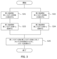
- FIG. 3 is a flow chart showing a modified example of the method for producing a halide solid electrolyte according to the second embodiment.
- a method is described here in which the above (A-1) to (A-4) are carried out as the above (A), which is an example of the production method described in the first embodiment, and in which the halide solid electrolyte is slurried for forming a coating film at the same time as the mechanochemical treatment during the grinding treatment of the above (B).
- the first composition and the first halogen-containing substance are mixed (S31) as a process corresponding to the above (A-1), and the second composition and the second halogen-containing substance are mixed (S32) as a process corresponding to the above (A-3).
- the first mixture containing the first composition and the first halogen-containing substance obtained in the above (A-1) is heat-treated to convert the first composition into the first halide (S33).
- the second mixture containing the second composition and the second halogen-containing substance obtained in the above (A-3) is heat-treated to convert the second composition into the second halide (S34).
- the first halide and the second halide are subjected to mechanochemical treatment and simultaneously slurried (S35).
- S31 to S34 are the same as S11 to S14 described in the first embodiment, so detailed explanations will be omitted here.
- the mechanochemical treatment is the same as the grinding treatment in S25 described as an example of the manufacturing method of the second embodiment.
- a slurrying treatment is further carried out.
- the slurrying treatment is carried out, for example, by adding an organic binder and a plasticizer, etc., dispersed in an organic solvent such as tetralin, to the halide solid electrolyte at the same time as the grinding treatment.
- An example of the organic binder is, for example, styrene butadiene block copolymer (SBS).
- An example of the plasticizer is, for example, bisbutyl phthalate (DBP) and butyl benzyl phthalate (BBP).
- the obtained halide solid electrolyte slurry can be used for printing or coating.
- the thickness of the coating film can be, for example, 10 ⁇ m or more and 100 ⁇ m or less, and this allows, for example, a slurry of a pulverized halide solid electrolyte containing an amorphous portion to be directly coated.
- an organic binder, a plasticizer, etc. can be added in the pulverization process to prepare a slurry of the halide solid electrolyte, and the slurry can be used to form a coating film.
- This allows the formation of a coating film of a halide solid electrolyte with excellent properties.
- Such a coating film can be used, for example, in the manufacture of a coated cell.
- a first halogen-containing material is heat-treated to generate a first halogen gas, and the first composition is converted into the first halide by contacting the first halogen gas with the first composition.
- a second halogen-containing material is heat-treated to generate a second halogen gas, and the second composition is converted into the second halide by contacting the second halogen gas with the second composition.
- the above (A) may be followed by the mechanochemical treatment of (B) described in the second embodiment.
- FIG. 4 is a flow chart showing an example of a method for producing a halide solid electrolyte according to the third embodiment.
- a first composition is placed at a predetermined position, and a first halogen-containing material is heat-treated to bring the generated halogen gas into contact with the first composition (S41). This performs a halogenation treatment on the first composition.
- a second composition is placed at a predetermined position, and a second halogen-containing material is heat-treated to bring the generated halogen gas into contact with the second composition (S42).
- S41 a first halogen-containing material
- S42 second halogen-containing material
- the first composition can be halogenated by the generated halogen gas without directly contacting the first composition with the first halogen-containing material. Therefore, even if a halogen-containing material containing an inorganic component other than the halogen element is used, it is not necessary to consider inorganic residues in the manufactured halide solid electrolyte. Therefore, the range of usable first halogen-containing materials can be expanded.
- the second composition can be halogenated by the generated halogen gas without directly contacting the second composition with the second halogen-containing material.
- the first composition is placed on a fine-meshed nickel net, and the first halogen-containing material, such as ammonium fluoride, is placed under the nickel net.
- the first composition and the halogen-containing material are placed without contacting each other.
- a halogen gas such as fluorine gas
- the gas passes through the nickel net and comes into contact with the first composition.
- the first composition is converted into the first halide.
- the first composition and the halide are as described in the first embodiment.
- the heat treatment can be performed in the air, but it is preferable to perform the heat treatment in a nitrogen atmosphere or a reducing atmosphere so as not to oxidize the nickel net.
- the halogenation of the second composition is performed in the same manner.
- the battery according to the fourth embodiment includes a positive electrode, an electrolyte layer, and a negative electrode.
- the electrolyte layer is provided between the positive electrode and the negative electrode.
- At least one selected from the group consisting of the positive electrode, the electrolyte layer, and the negative electrode includes a halide solid electrolyte that includes Li, Ti, Al, and F, and further includes at least one selected from the group consisting of K and Fe.
- the halide solid electrolyte can be manufactured, for example, by the manufacturing method according to the first embodiment, the second embodiment, or the third embodiment.
- the halide solid electrolyte contained in the battery according to the fourth embodiment which contains Li, Ti, Al, and F and further contains at least one selected from the group consisting of K and Fe, will be referred to as the halide solid electrolyte according to the fourth embodiment.
- the halide solid electrolyte according to the fourth embodiment may consist essentially of Li, Ti, Al, F, K, and Fe, as described in the first, second, or third embodiment as an example of a halide solid electrolyte that can be manufactured by the manufacturing method according to the first, second, or third embodiment, or may consist only of Li, Ti, Al, F, K, and Fe.
- the halide solid electrolyte according to the fourth embodiment may be particulate.
- the halide solid electrolyte according to the fourth embodiment may include an amorphous phase, as described in the second embodiment.
- the battery according to the fourth embodiment has excellent charge/discharge characteristics because it contains the halide solid electrolyte according to the fourth embodiment.
- FIG. 5 shows a cross-sectional view of a battery 1000 according to a fourth embodiment.
- the battery 1000 according to the fourth embodiment includes a positive electrode 201, an electrolyte layer 202, and a negative electrode 203.
- the electrolyte layer 202 is provided between the positive electrode 201 and the negative electrode 203.
- the positive electrode 201 may include a positive electrode material including a halide solid electrolyte according to the fourth embodiment.
- the positive electrode 201 contains a positive electrode active material 204 and a solid electrolyte 100.
- the electrolyte layer 202 contains an electrolyte material.
- the negative electrode 203 contains a negative electrode active material 205 and a solid electrolyte 100.
- the solid electrolyte 100 includes, for example, the halide solid electrolyte according to the fourth embodiment.
- the solid electrolyte 100 may be particles containing the halide solid electrolyte according to the fourth embodiment as a main component. Particles containing the halide solid electrolyte according to the fourth embodiment as a main component refer to particles in which the component contained most abundantly in terms of molar ratio is the halide solid electrolyte according to the fourth embodiment.
- the solid electrolyte 100 may be particles made of the halide solid electrolyte according to the fourth embodiment.
- the positive electrode 201 contains a material capable of absorbing and releasing metal ions (e.g., lithium ions).
- the material is, for example, the positive electrode active material 204.
- Examples of the positive electrode active material 204 include lithium-containing transition metal oxides, transition metal fluorides, polyanions, fluorinated polyanion materials, transition metal sulfides, transition metal oxyfluorides, transition metal oxysulfides, or transition metal oxynitrides.
- Examples of lithium-containing transition metal oxides include Li(Ni,Co,Mn) O2 , Li(Ni,Co,Al) O2 , or LiCoO2 .
- (A, B, C) means "at least one selected from the group consisting of A, B, and C.”
- the shape of the positive electrode active material 204 is not limited to a specific shape.
- the positive electrode active material 204 may be particles.
- the positive electrode active material 204 may have a median diameter of 0.1 ⁇ m or more and 100 ⁇ m or less. When the positive electrode active material 204 has a median diameter of 0.1 ⁇ m or more, the positive electrode active material 204 and the solid electrolyte 100 can be well dispersed in the positive electrode 201. This improves the charge and discharge characteristics of the battery 1000. When the positive electrode active material 204 has a median diameter of 100 ⁇ m or less, the lithium diffusion rate in the positive electrode active material 204 improves. This allows the battery 1000 to operate at high power.
- the positive electrode active material 204 may have a median diameter larger than that of the solid electrolyte 100. This allows the positive electrode active material 204 and the solid electrolyte 100 to be well dispersed in the positive electrode 201.
- the ratio of the volume of the positive electrode active material 204 to the sum of the volume of the positive electrode active material 204 and the volume of the solid electrolyte 100 may be 0.30 or more and 0.95 or less.
- a coating layer may be formed on at least a portion of the surface of the positive electrode active material 204.
- the coating layer may be formed on the surface of the positive electrode active material 204, for example, before mixing with the conductive assistant and the binder.
- coating materials included in the coating layer are sulfide solid electrolyte, oxide solid electrolyte, or halide solid electrolyte.
- the coating material may contain a halide solid electrolyte according to the fourth embodiment in order to suppress oxidative decomposition of the sulfide solid electrolyte.
- the coating material may contain an oxide solid electrolyte in order to suppress oxidative decomposition of the solid electrolyte.
- Lithium niobate which has excellent stability at high potentials, may be used as the oxide solid electrolyte. By suppressing oxidative decomposition, the overvoltage rise of the battery 1000 can be suppressed.
- the positive electrode material may include the halide solid electrolyte according to the fourth embodiment as the solid electrolyte 100, or may include it as a coating material that coats the positive electrode active material 204.
- the positive electrode 201 may have a thickness of 10 ⁇ m or more and 500 ⁇ m or less.
- the electrolyte layer 202 contains an electrolyte material.
- the electrolyte material is, for example, a solid electrolyte.
- the solid electrolyte may include the halide solid electrolyte according to the fourth embodiment.
- the electrolyte layer 202 may be a solid electrolyte layer.
- the electrolyte layer 202 may contain 50% by mass or more of the halide solid electrolyte according to the fourth embodiment.
- the electrolyte layer 202 may contain 70% by mass or more of the halide solid electrolyte according to the fourth embodiment.
- the electrolyte layer 202 may contain 90% by mass or more of the halide solid electrolyte according to the fourth embodiment.
- the electrolyte layer 202 may consist of only the halide solid electrolyte according to the fourth embodiment.
- the halide solid electrolyte according to the fourth embodiment will be referred to as the first solid electrolyte.
- a solid electrolyte different from the first solid electrolyte will be referred to as the second solid electrolyte.
- the electrolyte layer 202 may contain not only the first solid electrolyte but also the second solid electrolyte. In the electrolyte layer 202, the first solid electrolyte and the second solid electrolyte may be uniformly dispersed. A layer made of the first solid electrolyte and a layer made of the second solid electrolyte may be stacked along the stacking direction of the battery 1000.
- the battery according to the fourth embodiment may include a positive electrode 201, a second electrolyte layer, a first electrolyte layer, and a negative electrode 203 in this order.
- the solid electrolyte contained in the first electrolyte layer may have a lower reduction potential than the solid electrolyte contained in the second electrolyte layer. This allows the solid electrolyte contained in the second electrolyte layer to be used without being reduced. As a result, the charge/discharge efficiency of the battery 1000 can be improved.
- the first electrolyte layer may contain a sulfide solid electrolyte in order to suppress the reductive decomposition of the solid electrolyte.
- the second electrolyte layer may contain the first solid electrolyte. Since the first solid electrolyte has high oxidation resistance, a battery with excellent charge/discharge characteristics can be realized.
- the electrolyte layer 202 may consist only of the second solid electrolyte.
- the electrolyte layer 202 may have a thickness of 1 ⁇ m or more and 1000 ⁇ m or less. If the electrolyte layer 202 has a thickness of 1 ⁇ m or more, the positive electrode 201 and the negative electrode 203 are less likely to short-circuit. If the electrolyte layer 202 has a thickness of 1000 ⁇ m or less, the battery 1000 can operate at high power.
- Examples of the second solid electrolyte are Li2MgX4 , Li2FeX4 , Li(Al,Ga,In) X4 , Li3 (Al,Ga,In) X6 , or LiI, where X is at least one selected from the group consisting of F, Cl, Br, and I.
- the electrolyte layer 202 may have a thickness of 1 ⁇ m or more and 1000 ⁇ m or less.
- the negative electrode 203 contains a material capable of absorbing and releasing metal ions (e.g., lithium ions).
- the material is, for example, the negative electrode active material 205.
- Examples of the negative electrode active material 205 are metal materials, carbon materials, oxides, nitrides, tin compounds, or silicon compounds.
- the metal material may be a single metal or an alloy.
- Examples of the metal material are lithium metal or lithium alloys.
- Examples of the carbon material are natural graphite, coke, partially graphitized carbon, carbon fiber, spherical carbon, artificial graphite, or amorphous carbon. From the viewpoint of capacity density, suitable examples of the negative electrode active material are silicon (i.e., Si), tin (i.e., Sn), silicon compounds, or tin compounds.
- the negative electrode active material 205 may be selected in consideration of the reduction resistance of the solid electrolyte contained in the negative electrode 203.
- the negative electrode active material 205 may be a material capable of absorbing and releasing lithium ions at 0.27 V or more relative to lithium.
- examples of such negative electrode active materials are titanium oxide, indium metal , or lithium alloy.
- examples of titanium oxide are Li4Ti5O12 , LiTi2O4 , or TiO2 .
- the shape of the negative electrode active material 205 is not limited to a specific shape.
- the negative electrode active material 205 may be particles.
- the negative electrode active material 205 may have a median diameter of 0.1 ⁇ m or more and 100 ⁇ m or less.
- the negative electrode active material 205 and the solid electrolyte 100 can be well dispersed in the negative electrode 203. This improves the charge and discharge characteristics of the battery 1000.
- the negative electrode active material 205 has a median diameter of 100 ⁇ m or less, the lithium diffusion rate in the negative electrode active material 205 improves. This allows the battery 1000 to operate at a high output.
- the negative electrode active material 205 may have a median diameter larger than that of the solid electrolyte 100. This allows the negative electrode active material 205 and the solid electrolyte 100 to be well dispersed in the negative electrode 203.
- the ratio of the volume of the negative electrode active material 205 to the sum of the volume of the negative electrode active material 205 and the volume of the solid electrolyte 100 may be 0.30 or more and 0.95 or less.
- the negative electrode 203 may have a thickness of 10 ⁇ m or more and 500 ⁇ m or less.
- At least one selected from the group consisting of the positive electrode 201, the electrolyte layer 202, and the negative electrode 203 may contain a second solid electrolyte for the purpose of increasing ionic conductivity, chemical stability, and electrochemical stability.
- the second solid electrolyte may be a sulfide solid electrolyte.
- Examples of sulfide solid electrolytes are Li2S - P2S5 , Li2S - SiS2 , Li2S - B2S3 , Li2S - GeS2 , Li3.25Ge0.25P0.75S4 , or Li10GeP2S12 .
- the negative electrode 203 may contain a sulfide solid electrolyte to suppress reductive decomposition of the solid electrolyte.
- the electrochemically stable sulfide solid electrolyte covers the negative electrode active material, thereby suppressing contact of the first solid electrolyte with the negative electrode active material. As a result, the internal resistance of the battery 1000 can be reduced.
- the second solid electrolyte may be an oxide solid electrolyte.
- oxide solid electrolytes include: (i) NASICON-type solid electrolytes such as LiTi2 ( PO4 ) 3 or elemental substitutions thereof; (ii) Perovskite-type solid electrolytes such as (LaLi) TiO3 ; (iii ) LISICON-type solid electrolytes such as Li14ZnGe4O16, Li4SiO4 , LiGeO4 or elemental substitutions thereof ; ( iv) garnet-type solid electrolytes such as Li7La3Zr2O12 or elemental substitutions thereof ; or (v) Li3PO4 or its N -substituted derivatives; It is.
- the second solid electrolyte may be a halide solid electrolyte.
- halide solid electrolytes are Li2MgX4 , Li2FeX4 , Li(Al,Ga,In) X4 , Li3 (Al,Ga,In) X6 , or LiI, where X is at least one selected from the group consisting of F, Cl, Br, and I.
- halide solid electrolyte is a compound represented by Li a Me b Y c Z 6.
- Me is at least one selected from the group consisting of metal elements other than Li and Y and metalloid elements.
- Z is at least one selected from the group consisting of F, Cl, Br, and I.
- m represents the valence of Me.
- Metalloid elements are B, Si, Ge, As, Sb, and Te.
- Metal elements are all elements included in Groups 1 to 12 of the periodic table (excluding hydrogen), and all elements included in Groups 13 to 16 of the periodic table (excluding B, Si, Ge, As, Sb, Te, C, N, P, O, S, and Se).
- Me may be at least one selected from the group consisting of Mg, Ca, Sr, Ba, Zn, Sc, Al, Ga, Bi, Zr, Hf, Ti, Sn, Ta, and Nb.
- the halide solid electrolyte may be Li3YCl6 or Li3YBr6 .
- the second solid electrolyte may be an organic polymer solid electrolyte.
- organic polymer solid electrolytes examples include polymer compounds and lithium salt compounds.
- the polymer compound may have an ethylene oxide structure.
- a polymer compound having an ethylene oxide structure can contain a large amount of lithium salt, and therefore can further increase the ionic conductivity.
- lithium salt examples include LiPF6 , LiBF4 , LiSbF6, LiAsF6 , LiSO3F3 , LiN ( SO2CF3 ) 2 , LiN (SO2C2F5)2, LiN(SO2CF3)(SO2C4F9), or LiC(SO2CF3)3 .
- One type of lithium salt selected from these may be used alone. Alternatively, a mixture of two or more types of lithium salts selected from these may be used.
- At least one selected from the group consisting of the positive electrode 201, the electrolyte layer 202, and the negative electrode 203 may contain a nonaqueous electrolyte, a gel electrolyte, or an ionic liquid to facilitate the transfer of lithium ions and improve the output characteristics of the battery.
- the non-aqueous electrolyte contains a non-aqueous solvent and a lithium salt dissolved in the non-aqueous solvent.
- non-aqueous solvents examples include cyclic carbonate solvents, chain carbonate solvents, cyclic ether solvents, chain ether solvents, cyclic ester solvents, chain ester solvents, or fluorine solvents.
- cyclic carbonate solvents are ethylene carbonate, propylene carbonate, or butylene carbonate.
- chain carbonate solvents are dimethyl carbonate, ethyl methyl carbonate, or diethyl carbonate.
- Examples of cyclic ether solvents are tetrahydrofuran, 1,4-dioxane, or 1,3-dioxolane.
- chain ether solvents are 1,2-dimethoxyethane or 1,2-diethoxyethane.
- An example of a cyclic ester solvent is ⁇ -butyrolactone.
- An example of a chain ester solvent is methyl acetate.
- fluorine solvents are fluoroethylene carbonate, methyl fluoropropionate, fluorobenzene, fluoroethyl methyl carbonate, or fluorodimethylene carbonate.
- One nonaqueous solvent selected from these may be used alone. Alternatively, a combination of two or more nonaqueous solvents selected from these may be used.
- lithium salt examples include LiPF6 , LiBF4 , LiSbF6, LiAsF6 , LiSO3CF3 , LiN ( SO2CF3 ) 2 , LiN ( SO2C2F5 ) 2 , LiN( SO2CF3 )(SO2C4F9), or LiC( SO2CF3 ) 3 .
- One type of lithium salt selected from these may be used alone. Alternatively, a mixture of two or more types of lithium salts selected from these may be used.
- the concentration of the lithium salt is, for example , in the range of 0.5 mol/L or more and 2 mol/L or less.
- a polymer material impregnated with a non-aqueous electrolyte may be used.
- polymer materials are polyethylene oxide, polyacrylonitrile, polyvinylidene fluoride, polymethyl methacrylate, or a polymer having an ethylene oxide bond.
- cations contained in ionic liquids are: (i) Aliphatic chain quaternary salts such as tetraalkylammonium or tetraalkylphosphonium; (ii) aliphatic cyclic ammoniums such as pyrrolidiniums, morpholiniums, imidazoliniums, tetrahydropyrimidiniums, piperaziniums, or piperidiniums, or (iii) nitrogen-containing heterocyclic aromatic cations such as pyridiniums or imidazoliums.
- Aliphatic chain quaternary salts such as tetraalkylammonium or tetraalkylphosphonium
- aliphatic cyclic ammoniums such as pyrrolidiniums, morpholiniums, imidazoliniums, tetrahydropyrimidiniums, piperaziniums, or piperidiniums
- nitrogen-containing heterocyclic aromatic cations such as
- Examples of anions contained in the ionic liquid are PF6- , BF4- , SbF6- , AsF6- , SO3CF3- , N ( SO2CF3 ) 2- , N ( SO2C2F5 ) 2- , N( SO2CF3 ) ( SO2C4F9 ) - , or C ( SO2CF3 ) 3- .
- the ionic liquid may contain a lithium salt.
- At least one selected from the group consisting of the positive electrode 201, the electrolyte layer 202, and the negative electrode 203 may contain a binder to improve adhesion between particles.
- binders are polyvinylidene fluoride, polytetrafluoroethylene, polyethylene, polypropylene, aramid resins, polyamides, polyimides, polyamideimides, polyacrylonitrile, polyacrylic acid, polymethyl esters of acrylic acid, polyethyl esters of acrylic acid, polyhexyl esters of acrylic acid, polymethacrylic acid, polymethyl esters of methacrylic acid, polyethyl esters of methacrylic acid, polyhexyl esters of methacrylic acid, polyvinyl acetate, polyvinylpyrrolidone, polyethers, polyethersulfones, hexafluoropolypropylene, styrene butadiene rubber, or carboxymethylcellulose.
- Copolymers may also be used as binders.
- binders are copolymers of two or more materials selected from the group consisting of tetrafluoroethylene, hexafluoroethylene, hexafluoropropylene, perfluoroalkyl vinyl ethers, vinylidene fluoride, chlorotrifluoroethylene, ethylene, propylene, pentafluoropropylene, fluoromethyl vinyl ether, acrylic acid, and hexadiene.
- a mixture of two or more materials selected from these may be used as a binder.
- At least one selected from the positive electrode 201 and the negative electrode 203 may contain a conductive additive to improve electronic conductivity.
- Examples of the conductive additive include: (i) graphites, such as natural or synthetic graphite; (ii) Carbon blacks such as acetylene black or ketjen black; (iii) conductive fibers, such as carbon or metal fibers; (iv) fluorocarbons, (v) metal powders such as aluminum; (vi) conductive whiskers such as zinc oxide or potassium titanate; (vii) a conductive metal oxide such as titanium oxide, or (viii) a conductive polymer compound such as polyaniline, polypyrrole, or polythiophene.
- the conductive assistant of (i) or (ii) above may be used.
- a separator impregnated with an electrolyte solution may be used instead of the electrolyte layer, and the exterior housing that houses the positive electrode, the separator portion, and the negative electrode may be filled with the electrolyte solution.
- the electrolyte solution may be, for example, the nonaqueous electrolyte solution described above.
- shapes of the battery according to the fourth embodiment include a coin type, a cylindrical type, a square type, a sheet type, a button type, a flat type, or a laminated type.
- the battery according to the fourth embodiment may be manufactured, for example, by preparing a material for forming a positive electrode, a material for forming an electrolyte layer, and a material for forming a negative electrode, and producing a laminate in which the positive electrode, electrolyte layer, and negative electrode are arranged in this order using a known method.
- Titanium halide (TiX 4 ) is a relatively unstable substance, such as being easily evaporated and having deliquescent properties. According to the manufacturing method of technology 1, the first composition containing Li, Ti, and O can be used as the Ti source. Therefore, according to the manufacturing method of technology 1, in the synthesis of the halide solid electrolyte containing Ti, it is not necessary to use the unstable titanium halide as a raw material, and titanium halide is difficult to generate in the synthesis process. In the conventional manufacturing method, titanium halide was usually used as the Ti source for the synthesis of the halide solid electrolyte containing Ti.
- composition fluctuation i.e., composition deviation
- deterioration e.g., inclusion of moisture, etc.
- the manufacturing method of technology 1 such composition fluctuations are unlikely to occur, and for example, a Ti-containing halide solid electrolyte having excellent properties such as ion conductivity can be synthesized reproducibly and stably. That is, according to the manufacturing method of Technique 1, a halide solid electrolyte having a target composition can be stably synthesized.
- (Technique 2) (A) comprises converting a second composition comprising Li, M, and O into the second halide;
- the first halide and the second halide obtained in the step (A) are used to synthesize the halide solid electrolyte.
- the manufacturing method of Technology 2 allows for the stable synthesis of a halide solid electrolyte having the desired composition.
- the step (B) includes mixing the first halide and the second halide; 3.
- the manufacturing method of Technology 3 allows the content ratio of the first halide and the second halide to be controlled and then mixed to homogenize. Therefore, it is possible to obtain a halide solid electrolyte having the desired composition with excellent ionic conductivity and stability.
- the step (B) includes heat treating the first halide and the second halide; 4.
- the first halide and the second halide can be reacted at a desired content ratio to obtain a halide solid electrolyte having a desired composition with excellent ionic conductivity and stability.
- the step (B) includes mechanochemically treating the first halide and the second halide; 5.
- the manufacturing method of Technology 5 allows the first halide to react with the second halide, and allows a portion of the synthesized halide solid electrolyte to be made amorphous. This makes it possible to obtain a halide solid electrolyte having a desired composition with excellent ionic conductivity and stability.
- the synthesized halide solid electrolyte can be made into fine particles, making it possible to obtain a halide solid electrolyte that is useful for the solid electrolyte layer of a battery, the coating layer of an active material, and the like. This makes it possible to realize a battery with excellent performance and reliability.
- the first halide comprises Li2TiX16
- the second halide comprises Li3MX26
- the halide solid electrolyte includes a first crystal phase represented by the following composition formula (1) and a second crystal phase represented by the following composition formula (2): 6.
- the manufacturing method of Technology 6 suppresses the generation of unstable halides (e.g., titanium halides) that are easily evaporated. Therefore, a halide solid electrolyte with good characteristics can be obtained stably and reproducibly in an air environment.
- unstable halides e.g., titanium halides
- the M includes Al. 7.
- the manufacturing method of Technology 7 makes it possible to obtain a halide solid electrolyte with high ionic conductivity.
- the manufacturing method of Technology 8 makes it possible to obtain a halide solid electrolyte that is highly stable (e.g., has excellent electrochemical stability and heat resistance) and has high ionic conductivity.
- the halogenation of at least one selected from the group consisting of the first composition and the second composition can be efficiently performed in a short time. Furthermore, since the halogenation can be performed by a short heat treatment, it is possible to obtain a solid electrolyte with homogeneous and excellent properties while reducing reaction residues such as oxides. Furthermore, since the first composition is converted into the first halide by heat treating the first halogen-containing material having thermal decomposition properties, the reactivity (halogenation property) of the first composition is good and the productivity is also excellent.
- the second composition is converted into the first halide by heat treating the second halogen-containing material having thermal decomposition properties
- the reactivity (halogenation property) of the second composition is good and the productivity is also excellent.
- the temperature of the halogenation reaction of the first composition and the progress of the reaction can be controlled according to the thermal decomposition temperature of the substance selected as the first halogen-containing substance.
- the temperature of the halogenation reaction of the second composition and the progress of the reaction can be controlled according to the thermal decomposition temperature of the substance selected as the second halogen-containing substance. Therefore, a process suitable for various halide solid electrolytes can be performed.
- the manufacturing method of Technology 10 at least one selected from the group consisting of the first halogen-containing substance and the second halogen-containing substance is easily thermally decomposed, and the contact area between the first halogen-containing substance and the first composition and/or the contact area between the second halogen-containing substance and the second composition is increased. Therefore, according to the manufacturing method of Technology 10, the first composition and/or the second composition can be efficiently halogenated, and the first halogen-containing substance and/or the second halogen-containing substance are unlikely to remain in the finally obtained halide solid electrolyte. In addition, precise control of the amount of halogen is possible. Therefore, it is possible to synthesize a desired halide solid electrolyte.
- first halogen-containing substance can be used in an amount necessary for halogenating the first composition, excess halogen gas emission can be suppressed.
- second halogen-containing substance can be used in an amount necessary for halogenating the second composition, excess halogen gas emission can be suppressed. This reduces the burden on the environment and also reduces the impact on corrosion of furnace materials, etc.
- step (I) When the step (I) is carried out in the step (A), the step (A) is (A-1) mixing the first composition with the first halogen-containing substance; (A-2) heat-treating the mixture containing the first composition and the first halogen-containing substance obtained in (A-1) to convert the first composition into the first halide; Including, When the step (II) is carried out in the step (A), the step (A) is (A-3) mixing the second composition with the second halogen-containing material; (A-4) heat-treating the mixture containing the second composition and the second halogen-containing substance obtained in (A-3) to convert the second composition into the second halide; Including, 11.
- a heat treatment for halogenation can be performed on a homogeneous mixture of the first composition and the first halogen-containing substance.
- a heat treatment for halogenation can be performed on a homogeneous mixture of the second composition and the second halogen-containing substance.
- the contact area between the first composition and the first halogen-containing substance can be increased.
- the contact area between the second composition and the second halogen-containing substance can be increased. Therefore, according to the manufacturing method of Technology 11, the halogenation of the first composition and/or the second composition can be promoted homogeneously. Therefore, a homogeneous halide solid electrolyte having excellent properties can be obtained.
- step (I) When the step (I) is carried out in the step (A), in the step (A), a first halogen-containing material is heat-treated to generate a first halogen gas, and the first composition is converted into the first halide by contacting the first halogen gas with the first composition;
- a second halogen-containing material is heat-treated to generate a second halogen gas, and the second composition is contacted with the second halogen gas to convert the second composition into the second halide.
- the method for producing a halide solid electrolyte according to any one of claims 9 to 11.
- the first composition can be halogenated by the generated halogen gas without directly contacting the first composition with the first halogen-containing material.
- the second composition can be halogenated by the generated halogen gas without directly contacting the second composition with the second halogen-containing material. Therefore, even if a halogen-containing material containing an inorganic component in addition to a halogen element is used, there is no need to consider inorganic residues in the manufactured halide solid electrolyte. Therefore, the range of usable first halogen-containing materials and/or second halogen-containing materials can be expanded.
- Ammonium salts begin to decompose thermally at relatively low temperatures (e.g., about 150°C). Therefore, ammonium salts are unlikely to remain as unnecessary inorganic components in the final halide solid electrolyte, and can be thermally decomposed at low temperatures to halogenate the first composition and/or the second composition. Therefore, according to the manufacturing method of Technology 13, it is possible to prevent unnecessary inorganic components derived from halogen-containing materials from remaining in the final halide solid electrolyte. Furthermore, energy saving is achieved in the synthesis, and the temperature rise and fall times are also reduced, improving productivity. In addition, since synthesis is possible at low temperatures, the durability of the furnace material is improved, and the running costs and replacement frequency of the synthesis components are significantly reduced.
- the ammonium salt comprises NH4F . 14.
- the manufacturing method of technology 14 is effective in halogenating the first composition and/or the second composition at a low temperature (for example, 150°C to 200°C).
- a low temperature for example, 150°C to 200°C.
- the phenomenon of the first halide being sintered and becoming too hard is unlikely to occur, so a soft first halide can be obtained.
- the phenomenon of the second halide being sintered and becoming too hard is unlikely to occur, so a soft second halide can be obtained. Therefore, according to the manufacturing method of technology 14, a halide solid electrolyte useful for the solid electrolyte layer of a battery, the coating layer of an active material, etc. can be obtained. Thus, a battery with excellent performance and reliability can be realized.
- NH 4 F is a highly decomposable fluorine source and can effectively act on the halogenation of the first composition and/or the second composition. Therefore, according to the manufacturing method of technology 14, NH 4 F can be thermally decomposed at a low temperature (for example, about 150°C to 200°C) and at a high decomposition rate, while halogenating the first composition and/or the second composition without remaining in the first halide and/or the second halide.
- a low temperature for example, about 150°C to 200°C
- the first halogen-containing material can halogenate the first composition while being thermally decomposed at a relatively high temperature (e.g., about 450°C or higher and 600°C or lower).
- the second halogen-containing material can halogenate the second composition while being thermally decomposed at a relatively high temperature (e.g., about 450°C or higher and 600°C or lower).
- the resin includes a fluororesin. 16.
- Fluororesins such as PTFE can halogenate the first composition and/or the second composition while being thermally decomposed at a relatively high temperature (e.g., about 450°C or higher and 600°C or lower).
- At least one selected from the group consisting of the first halogen-containing substance and the second halogen-containing substance includes a substance that does not substantially cause inorganic components generated by thermal decomposition by the heat treatment in (A) to be contained in the halide solid electrolyte, except for halogen elements. 17.
- the first halogen-containing material is required to replace the halogen element generated by the thermal decomposition by the heat treatment in (A) with the oxygen element of the oxide mixture, while other components are not mixed as inorganic residues into the finally obtained halide solid electrolyte.
- the second halogen-containing material is required to replace the halogen element generated by the thermal decomposition by the heat treatment in (A) with the oxygen element of the oxide mixture, while other components are not mixed as inorganic residues into the finally obtained halide solid electrolyte.
- halogen-containing materials that do not substantially include inorganic components generated by thermal decomposition by the heat treatment in the finally obtained halide solid electrolyte include substances in which inorganic components generated by thermal decomposition by the heat treatment, except for halogen elements, are exhausted as gas.
- both ammonium salt and fluororesin can be used as the first halogen-containing material and/or the second halogen-containing material.
- This allows for wide control of the temperature range in which the first halogen-containing material and/or the second halogen-containing material acts as a halogen source. Therefore, the conversion temperature of the first composition to the first halide can be controlled over a wide range. Similarly, the conversion temperature of the second composition to the second halide can be controlled over a wide range. Therefore, according to the manufacturing method of Technology 18, it becomes easy to obtain a desired halide solid electrolyte.
- This configuration results in a homogeneous halide solid electrolyte with excellent ionic conductivity.
- This configuration can suppress the change over time in the characteristics and mechanical properties of the halide solid electrolyte caused by the evaporation and deliquescence of TiF 4 , thereby realizing a halide solid electrolyte with excellent characteristics and reliability. Even if a small amount of TiF 4 is generated during the halogenation process of the first composition, the halogenation process is performed in an open state, so that TiF 4 can be evaporated and eliminated. Therefore, a halide solid electrolyte that does not substantially contain TiF 4 and has excellent characteristics and reliability can be obtained.
- the halide solid electrolyte is in particulate form. 21.
- Halide solid electrolytes have relatively soft properties. Therefore, according to this configuration, a relatively soft particulate solid electrolyte can be realized. Therefore, the compact of the halide solid electrolyte of Technology 21 has high ionic conductivity, excellent stability, and can have any shape. In addition, since it can have any shape, the compact of the halide solid electrolyte of Technology 21 has excellent deformability. Therefore, the compact of the halide solid electrolyte of Technology 21 can realize a solid electrolyte layer of a battery with excellent characteristics and high reliability. The size and shape of the particles can be selected appropriately depending on the application.
- the halide solid electrolyte includes an amorphous phase. 22.
- the halide solid electrolyte compact can be configured to form a solid electrolyte layer with higher ionic conductivity and higher stability in any shape. Therefore, the halide solid electrolyte compact of Technology 22 can realize a solid electrolyte layer for a battery with excellent characteristics and high reliability.
- This configuration makes it possible to obtain a halide solid electrolyte with excellent characteristics and reliability.
- the positive electrode material developed by Technology 24 makes it possible to realize a battery with excellent charge/discharge characteristics.
- This configuration provides a battery with excellent charge/discharge characteristics.
- This configuration provides a battery with excellent charge/discharge characteristics.
- Example 1 As starting materials, Li2O powder (average particle diameter: approximately 1.5 ⁇ m) as a component of the first composition and the second composition, TiO2 powder (average particle diameter: approximately 0.8 ⁇ m, anatase type) as a component of the first composition, Al2O3 powder (average particle diameter: 0.4 ⁇ m) as a component of the second composition , NH4F powder (average particle diameter: approximately 35 ⁇ m) as the first halogen-containing substance and the second halogen-containing substance, and K2O powder (average particle diameter: approximately 0.7 ⁇ m) and Fe2O3 powder (average particle diameter: approximately 0.6 ⁇ m) as additives were prepared.
- Li2O powder average particle diameter: approximately 1.5 ⁇ m
- TiO2 powder average particle diameter: approximately 0.8 ⁇ m, anatase type
- Al2O3 powder average particle diameter: 0.4 ⁇ m
- NH4F powder average particle diameter: approximately 35 ⁇ m
- K2O powder average particle diameter: approximately 0.7 ⁇ m
- X is F
- M is Al.
- K 2 O powder and Fe 2 O 3 powder were weighed out so that KF was 0.3 mol% and FeF 3 was 0.01 mol% relative to [0.25Li 2 TiF 6 -0.75Li 3 AlF 6 ]. These starting materials were weighed out in an air atmosphere.
- the K and Fe components were contained in the first composition and the second composition at the above-mentioned contents in a molar ratio of 25:75, respectively.
- the NH4F powder was added in an amount necessary for fluorinating the first composition and the second composition. Specifically, an amount of NH4F was used that was sufficient to fluorinate the first composition and the second composition in the reaction formula.
- the first composition was composed of Li 2 O powder and TiO 2 powder.
- the second composition was composed of Li 2 O powder and Al 2 O 3 powder.
- the first composition and the first halogen-containing material (NH 4 F) were mixed with K 2 O and Fe 2 O 3 in the above molar ratio. This was mixed uniformly with a pestle in an alumina mortar for about 10 minutes (a step corresponding to the above (A-1)).
- the second composition and the second halogen-containing material (NH 4 F) were mixed with K 2 O and Fe 2 O 3 in the above molar ratio. This was mixed uniformly with a pestle in an alumina mortar for about 10 minutes (a step corresponding to the above (A-3)).
- the starting materials were mixed in normal air, as in the weighing process. This resulted in a first mixture in which the first composition, the halogen-containing substance, and the additive were mixed, and a second mixture in which the second composition, the halogen-containing substance, and the additive were mixed.
- SSA-H high-purity alumina crucibles (diameter ⁇ : 36 mm, height: 40 mm) were used. 3 g of the first mixture was placed in one crucible, and 3 g of the second mixture was placed in the other crucible, and each was heat-treated (steps corresponding to (A-2) and (A-4) above). A spacer (thickness 0.5 mm) was placed on the outer edge of the upper surface of the sheath to provide a gap so that the reactive gas (mainly ammonia) emitted during the heat treatment could easily escape, and an alumina plate-shaped lid was placed on top to prevent foreign objects from falling.
- reactive gas mainly ammonia
- the sheath with the lid placed on it was placed in the center of the firing furnace and heat-treated.
- the sheath was placed on a small heat capacity tsuku made of mullite with a porosity of about 20%.
- the scabbards were 10 mm long, 10 mm wide, and 10 mm high, and three scabbards were placed under each scabbard, floating the scabbard from the bottom of the furnace. In this way, the heater (radiation) heat and inert gas were allowed to reach the bottom of the scabbard.
- nitrogen gas was flowed in as an inert gas at 2 L/min from the inlet at the bottom of the furnace and exhausted from the exhaust port above the ceiling, and the gas continued to flow until the heat treatment was completed.
- the heat treatment temperature was 300°C.
- the first and second compositions which are made of oxides, were fluorinated, and the oxygen in each composition was replaced with fluorine, and a solid-phase reaction took place, synthesizing the first and second halides.
- an oxide was used as the starting material, which means that the raw material did not contain titanium halide.
- titanium halide was not easily generated during the synthesis process. Therefore, since no evaporative components such as titanium halide were included, in this embodiment, a reaction in a sealed container was not necessary, and heat treatment could be performed in the same manner as with general oxide ceramics.
- the first halide and the second halide were mixed in a molar ratio of 25:75, and the mixture was homogenized by dry mixing in a mortar for about 10 minutes, followed by a pulverization process (a process corresponding to (B) above).
- the pulverization process included a mechanochemical process. Specifically, a ball mill (volume: 1 L) lined with zirconia was used, and zirconia balls (diameter: 15 mm) and the first and second halides were placed in the ball mill, and pulverized for 20 hours. This produced the halide solid electrolyte of Example 1.
- halide solid electrolyte of Example 1 synthesized as described above was evaluated for its crystal phase, ionic conductivity, electronic conductivity, average particle size, and BET specific surface area.
- the crystal phase, ionic conductivity, average particle size, and BET specific surface area were evaluated for both the halide solid electrolyte before and after the grinding process, after the first halide and the second halide were mixed and homogenized.
- the halide solid electrolyte of Comparative Example 1 was also evaluated for its crystal phase.
- the halide solid electrolyte of Example 1 was also analyzed for trace components.
- Crystal Phase The crystal phase was confirmed by powder X-ray diffraction measurement both before and after the heat treatment and the grinding treatment.
- An X-ray diffraction device (MiniFlex600, manufactured by RIGAKU Corporation) was used for the measurement.
- Cu-K ⁇ radiation (wavelengths 1.5405 ⁇ and 1.5444 ⁇ ) was used as the X-ray source.
- FIG. 6A is a graph showing the X-ray diffraction pattern of the halide solid electrolyte after mixing and homogenizing the first halide and the second halide in the manufacturing method of Example 1 and before the pulverization treatment.
- FIG. 6B is a graph showing the X-ray diffraction pattern of the halide solid electrolyte after the pulverization treatment obtained in Example 1 and the halide solid electrolyte obtained in Comparative Example 1.
- Li 2 TiF 6 corresponding to the first crystal phase and Li 3 AlF 6 corresponding to the second crystal phase were confirmed in the halide solid electrolyte synthesized in Example 1.
- FIG. 6A Li 2 TiF 6 corresponding to the first crystal phase and Li 3 AlF 6 corresponding to the second crystal phase were confirmed in the halide solid electrolyte synthesized in Example 1.
- FIG. 6A Li 2 TiF 6 corresponding to the first crystal phase and Li 3 AlF 6 corresponding to the second crystal phase were confirmed in the halide solid electro
- Example 6B it can be confirmed that the halide solid electrolyte after the pulverization treatment obtained in Example 1 has the same crystal quality as the halide solid electrolyte of Comparative Example 1 obtained by mechanochemical synthesis using fluoride as a starting material. In addition, no extra precipitated phase was observed in the halide solid electrolyte of Example 1.
- the ionic conductivity was calculated from the area, thickness, and impedance characteristics at room temperature of a compact sample obtained by putting a halide solid electrolyte powder into a mold with a diameter of 10 mm and applying a pressure of about 3 t/cm using a uniaxial hydraulic press. The impedance measurement was performed at room temperature while applying pressure. The impedance measurement was performed at a measurement frequency of 10 Hz to 10 MHz, a measurement voltage of 1 Vrms, and no DC bias. The deviation in the electrical length of the cable and the measuring jig was offset and evaluated.
- the ionic conductivity before the pulverization treatment was 0.81 ⁇ S/cm
- the ionic conductivity after the pulverization treatment was 5.7 ⁇ S/cm.
- the electronic conductivity was calculated from the DC voltage and current characteristics.
- the electronic conductivity of the halide solid electrolyte of Example 1 was ⁇ 1.0 ⁇ 10 ⁇ 9 ⁇ S/cm, which was a value that could be determined to have no electronic conductivity.
- the average particle size is the value of the median diameter D50 obtained from the volumetric particle size distribution measured by a laser diffraction scattering type particle size distribution measuring device. Specifically, the powder of the halide solid electrolyte was dispersed in a 0.01 wt% aqueous solution of Na hexametaphosphate using a homogenizer, and then the particle size distribution of the halide solid electrolyte was measured using a laser diffraction scattering type particle size distribution measuring device (manufactured by Microtrac, product name: MT3100II). The value of D50 (i.e., cumulative 50% particle size) of the measured particle size distribution was regarded as the average particle size. For the halide solid electrolyte of Example 1, the average particle size before the pulverization treatment was 0.88 ⁇ m, and the average particle size after the pulverization treatment was 0.65 ⁇ m.
- the BET specific surface area was determined by a multipoint BET method using a nitrogen gas adsorption apparatus.
- the halide solid electrolyte of Example 1 had a BET specific surface area of 2.63 m 2 /g before the pulverization treatment and a BET specific surface area of 3.65 m 2 /g after the pulverization treatment.
- the trace components contained in the halide solid electrolyte were analyzed by EPMA. Specifically, the analysis was performed as follows. A sample (powder) of the halide solid electrolyte was attached to a conductive tape and fixed (the sample was fixed to a 5 mm x 5 mm area to form a solid), and the composition (quantitative) was examined by point analysis. Although not confirmed by X-ray diffraction measurement, it was confirmed that the halide solid electrolyte of Example 1 contained Nb and Ga. The content of K was 0.03 at. %, and the content of Fe was 0.003 at. %.
- Example 1 From the evaluation results of the halide solid electrolyte obtained in Example 1, it was found that the manufacturing method of the present disclosure was able to convert an oxide into a homogeneous halide, and as a result, a high ionic conductivity of 5.7 ⁇ S/cm was obtained. This ionic conductivity was equal to or higher than that of synthesis from a fluoride raw material, and the manufacturing method of the present disclosure was able to obtain a halide solid electrolyte with excellent properties. It was confirmed that the electronic conductivity was ⁇ 1.0 ⁇ 10 ⁇ 9 ⁇ S/cm, which was an ionically conductive solid electrolyte that did not have electronic conductivity (i.e., had a negligible level of electronic conductivity).
- Example 1 From the X-ray diffraction patterns shown in FIG. 6A and FIG. 6B, it was confirmed that the method of Example 1 can obtain a halide solid electrolyte containing Li 2 TiF 6 corresponding to the first crystal phase and Li 3 AlF 6 corresponding to the second crystal phase. In addition, from these X-ray diffraction patterns, it was confirmed that the halide solid electrolyte obtained in Example 1 has the same crystal quality as the halide solid electrolyte of Comparative Example 1 synthesized by the conventional method, and the composition fluctuation is suppressed compared to the halide solid electrolyte of Comparative Example 1.
- the X-ray diffraction pattern after the pulverization process changed to a broader peak than the X-ray diffraction pattern before the pulverization process, and the progress of amorphization was confirmed. However, no new precipitated phases due to the pulverization process appeared.
- the changes in ionic conductivity, average particle size, and BET specific surface area before and after the pulverization process are as described in the explanation of each evaluation item.
- the grinding treatment may or may not be performed depending on the application of the halide solid electrolyte, and that the composition and crystal phase of the halide solid electrolyte are almost unchanged regardless of whether the grinding treatment is performed or not, and therefore excellent properties are maintained.
- the amount of oxygen as an impurity in the halide solid electrolyte of Example 1 was 0.10% by mass, and it was confirmed that the oxygen in the oxide was converted to fluorine.
- the amount of oxygen was evaluated based on the measurement results by using a melt extraction type device to measure the gas (CO 2 , CO) generated by melting a sample (powder) of the halide solid electrolyte.
- the amount of oxygen in the halide solid electrolyte of Example 1 is rather lower than that of the halide solid electrolyte obtained by the synthesis method using fluoride as the starting material.
- the amount of oxygen in the halide solid electrolyte obtained by the synthesis method using fluoride as the starting material is usually more than 0.5% by mass and about 1.0% by mass or less. This is thought to be due to the fact that moisture or oxygen, etc., that was taken into the unstable fluoride raw material during the synthesis process, such as storage or handling, remains after synthesis.
- the fluoride raw material is mixed and subjected to a solid-phase reaction without using a sealed jig as in the manufacturing method of the present disclosure, the Ti component evaporates as titanium fluoride because it is open and disappears from the halide. For this reason, the composition varies, and only a material having a smaller ionic conductivity than that of Example 1 can be obtained. In this case, a high heat treatment temperature of 500° C. to 600° C. is also required for the synthesis.
- a halide solid electrolyte containing Li, Ti, M, and X can be produced by a normal synthesis process (i.e., without sealing, and in a synthesis environment in the atmosphere) with little compositional variation and with high ionic conductivity comparable to that of conventional manufacturing methods. Furthermore, whereas halide raw materials are extremely expensive, the manufacturing method disclosed herein uses inexpensive oxide raw materials, thereby reducing the manufacturing cost of the halide solid electrolyte.
- the method for producing a halide solid electrolyte according to the present disclosure can be used, for example, as a method for producing a solid electrolyte for secondary batteries such as all-solid-state batteries used in various electronic devices or automobiles.
Landscapes
- Conductive Materials (AREA)
- Secondary Cells (AREA)
Priority Applications (2)
| Application Number | Priority Date | Filing Date | Title |
|---|---|---|---|
| CN202480043832.3A CN121444180A (zh) | 2023-06-29 | 2024-06-06 | 卤化物固体电解质的制造方法、卤化物固体电解质、正极材料和电池 |
| JP2025529589A JPWO2025004750A1 (https=) | 2023-06-29 | 2024-06-06 |
Applications Claiming Priority (2)
| Application Number | Priority Date | Filing Date | Title |
|---|---|---|---|
| JP2023107588 | 2023-06-29 | ||
| JP2023-107588 | 2023-06-29 |
Publications (1)
| Publication Number | Publication Date |
|---|---|
| WO2025004750A1 true WO2025004750A1 (ja) | 2025-01-02 |
Family
ID=93938691
Family Applications (1)
| Application Number | Title | Priority Date | Filing Date |
|---|---|---|---|
| PCT/JP2024/020791 Ceased WO2025004750A1 (ja) | 2023-06-29 | 2024-06-06 | ハロゲン化物固体電解質の製造方法、ハロゲン化物固体電解質、正極材料、および電池 |
Country Status (3)
| Country | Link |
|---|---|
| JP (1) | JPWO2025004750A1 (https=) |
| CN (1) | CN121444180A (https=) |
| WO (1) | WO2025004750A1 (https=) |
Citations (4)
| Publication number | Priority date | Publication date | Assignee | Title |
|---|---|---|---|---|
| CN103107327A (zh) * | 2013-01-05 | 2013-05-15 | 宁波大学 | Ti4+,Al3+,Fe3+,F-掺杂层-尖晶石复合富锂正极材料及制备方法 |
| WO2021187391A1 (ja) | 2020-03-18 | 2021-09-23 | パナソニックIpマネジメント株式会社 | 正極材料、および、電池 |
| WO2021186809A1 (ja) | 2020-03-18 | 2021-09-23 | パナソニックIpマネジメント株式会社 | 固体電解質材料およびそれを用いた電池 |
| WO2023042567A1 (ja) * | 2021-09-15 | 2023-03-23 | パナソニックIpマネジメント株式会社 | 組成物、電池、および組成物の製造方法 |
-
2024
- 2024-06-06 JP JP2025529589A patent/JPWO2025004750A1/ja active Pending
- 2024-06-06 CN CN202480043832.3A patent/CN121444180A/zh active Pending
- 2024-06-06 WO PCT/JP2024/020791 patent/WO2025004750A1/ja not_active Ceased
Patent Citations (4)
| Publication number | Priority date | Publication date | Assignee | Title |
|---|---|---|---|---|
| CN103107327A (zh) * | 2013-01-05 | 2013-05-15 | 宁波大学 | Ti4+,Al3+,Fe3+,F-掺杂层-尖晶石复合富锂正极材料及制备方法 |
| WO2021187391A1 (ja) | 2020-03-18 | 2021-09-23 | パナソニックIpマネジメント株式会社 | 正極材料、および、電池 |
| WO2021186809A1 (ja) | 2020-03-18 | 2021-09-23 | パナソニックIpマネジメント株式会社 | 固体電解質材料およびそれを用いた電池 |
| WO2023042567A1 (ja) * | 2021-09-15 | 2023-03-23 | パナソニックIpマネジメント株式会社 | 組成物、電池、および組成物の製造方法 |
Also Published As
| Publication number | Publication date |
|---|---|
| CN121444180A (zh) | 2026-01-30 |
| JPWO2025004750A1 (https=) | 2025-01-02 |
Similar Documents
| Publication | Publication Date | Title |
|---|---|---|
| CN111492443B (zh) | 固体电解质材料和电池 | |
| US12542300B2 (en) | Solid electrolyte material and battery using same | |
| WO2019135341A1 (ja) | 固体電解質材料、および、電池 | |
| JP7769981B2 (ja) | 固体電解質材料およびそれを用いた電池 | |
| US20230103996A1 (en) | Solid electrolyte material, and battery in which same is used | |
| WO2019135342A1 (ja) | 固体電解質材料、および、電池 | |
| JP7731077B2 (ja) | 固体電解質材料およびそれを用いた電池 | |
| WO2025004749A1 (ja) | ハロゲン化物固体電解質の製造方法、ハロゲン化物固体電解質、正極材料、および電池 | |
| WO2022239352A2 (ja) | 固体電解質、固体電解質の製造方法、および電池 | |
| JP7808779B2 (ja) | 固体電解質材料およびそれを用いた電池 | |
| WO2025004750A1 (ja) | ハロゲン化物固体電解質の製造方法、ハロゲン化物固体電解質、正極材料、および電池 | |
| JP2025526790A (ja) | 固体電解質およびこれを含む全固体電池 | |
| JP7624636B2 (ja) | 固体電解質材料およびそれを用いた電池 | |
| JP7664537B2 (ja) | 固体電解質材料およびそれを用いた電池 | |
| WO2025004748A1 (ja) | ハロゲン化物固体電解質の製造方法、ハロゲン化物固体電解質、正極材料、および電池 | |
| WO2023199629A1 (ja) | 固体電解質材料およびそれを用いた電池 | |
| WO2023002827A1 (ja) | 正極材料および電池 | |
| WO2023195212A1 (ja) | オキシハロゲン化物材料、電池、および電池システム | |
| WO2025004753A1 (ja) | ハロゲン化物固体電解質の製造方法、ハロゲン化物固体電解質、正極材料、および電池 | |
| US20260116770A1 (en) | Halide solid electrolyte production method, halide solid electrolyte, positive electrode material, and battery | |
| KR20230165525A (ko) | 황화물계 고체전해질의 제조방법, 황화물계 고체전해질, 고체 전해질막 및 전고체 전지 | |
| WO2025004752A1 (ja) | 固体電解質の製造方法、固体電解質、正極材料、および電池 | |
| WO2022168780A1 (ja) | リチウム金属複合酸化物、リチウム二次電池用正極活物質、リチウム二次電池用正極及びリチウム二次電池 | |
| WO2025004751A1 (ja) | 固体電解質、固体電解質の製造方法、正極材料、および電池 | |
| JP7742580B2 (ja) | 固体電解質材料およびそれを用いた電池 |
Legal Events
| Date | Code | Title | Description |
|---|---|---|---|
| 121 | Ep: the epo has been informed by wipo that ep was designated in this application |
Ref document number: 24831620 Country of ref document: EP Kind code of ref document: A1 |
|
| ENP | Entry into the national phase |
Ref document number: 2025529589 Country of ref document: JP Kind code of ref document: A |
|
| WWE | Wipo information: entry into national phase |
Ref document number: 2025529589 Country of ref document: JP |
|
| WWE | Wipo information: entry into national phase |
Ref document number: 2024831620 Country of ref document: EP |
|
| NENP | Non-entry into the national phase |
Ref country code: DE |
|
| ENP | Entry into the national phase |
Ref document number: 2024831620 Country of ref document: EP Effective date: 20260129 |
|
| ENP | Entry into the national phase |
Ref document number: 2024831620 Country of ref document: EP Effective date: 20260129 |