WO2025004665A1 - 検出装置 - Google Patents
検出装置 Download PDFInfo
- Publication number
- WO2025004665A1 WO2025004665A1 PCT/JP2024/019489 JP2024019489W WO2025004665A1 WO 2025004665 A1 WO2025004665 A1 WO 2025004665A1 JP 2024019489 W JP2024019489 W JP 2024019489W WO 2025004665 A1 WO2025004665 A1 WO 2025004665A1
- Authority
- WO
- WIPO (PCT)
- Prior art keywords
- finger
- light
- unit
- sensor unit
- dark
- Prior art date
- Legal status (The legal status is an assumption and is not a legal conclusion. Google has not performed a legal analysis and makes no representation as to the accuracy of the status listed.)
- Ceased
Links
Images



Classifications
-
- G—PHYSICS
- G01—MEASURING; TESTING
- G01L—MEASURING FORCE, STRESS, TORQUE, WORK, MECHANICAL POWER, MECHANICAL EFFICIENCY, OR FLUID PRESSURE
- G01L1/00—Measuring force or stress, in general
- G01L1/24—Measuring force or stress, in general by measuring variations of optical properties of material when it is stressed, e.g. by photoelastic stress analysis using infrared, visible light, ultraviolet
- G01L1/248—Measuring force or stress, in general by measuring variations of optical properties of material when it is stressed, e.g. by photoelastic stress analysis using infrared, visible light, ultraviolet using infrared
-
- A—HUMAN NECESSITIES
- A61—MEDICAL OR VETERINARY SCIENCE; HYGIENE
- A61B—DIAGNOSIS; SURGERY; IDENTIFICATION
- A61B5/00—Measuring for diagnostic purposes; Identification of persons
- A61B5/02—Detecting, measuring or recording for evaluating the cardiovascular system, e.g. pulse, heart rate, blood pressure or blood flow
-
- A—HUMAN NECESSITIES
- A61—MEDICAL OR VETERINARY SCIENCE; HYGIENE
- A61B—DIAGNOSIS; SURGERY; IDENTIFICATION
- A61B5/00—Measuring for diagnostic purposes; Identification of persons
- A61B5/02—Detecting, measuring or recording for evaluating the cardiovascular system, e.g. pulse, heart rate, blood pressure or blood flow
- A61B5/02007—Evaluating blood vessel condition, e.g. elasticity, compliance
-
- A—HUMAN NECESSITIES
- A61—MEDICAL OR VETERINARY SCIENCE; HYGIENE
- A61B—DIAGNOSIS; SURGERY; IDENTIFICATION
- A61B5/00—Measuring for diagnostic purposes; Identification of persons
- A61B5/117—Identification of persons
- A61B5/1171—Identification of persons based on the shapes or appearances of their bodies or parts thereof
-
- A—HUMAN NECESSITIES
- A61—MEDICAL OR VETERINARY SCIENCE; HYGIENE
- A61B—DIAGNOSIS; SURGERY; IDENTIFICATION
- A61B90/00—Instruments, implements or accessories specially adapted for surgery or diagnosis and not covered by any of the groups A61B1/00 - A61B50/00, e.g. for luxation treatment or for protecting wound edges
- A61B90/06—Measuring instruments not otherwise provided for
-
- G—PHYSICS
- G06—COMPUTING OR CALCULATING; COUNTING
- G06T—IMAGE DATA PROCESSING OR GENERATION, IN GENERAL
- G06T7/00—Image analysis
-
- G—PHYSICS
- G06—COMPUTING OR CALCULATING; COUNTING
- G06V—IMAGE OR VIDEO RECOGNITION OR UNDERSTANDING
- G06V40/00—Recognition of biometric, human-related or animal-related patterns in image or video data
- G06V40/10—Human or animal bodies, e.g. vehicle occupants or pedestrians; Body parts, e.g. hands
- G06V40/14—Vascular patterns
-
- G—PHYSICS
- G06—COMPUTING OR CALCULATING; COUNTING
- G06V—IMAGE OR VIDEO RECOGNITION OR UNDERSTANDING
- G06V40/00—Recognition of biometric, human-related or animal-related patterns in image or video data
- G06V40/10—Human or animal bodies, e.g. vehicle occupants or pedestrians; Body parts, e.g. hands
- G06V40/14—Vascular patterns
- G06V40/145—Sensors therefor
-
- G—PHYSICS
- G08—SIGNALLING
- G08B—SIGNALLING SYSTEMS, e.g. PERSONAL CALLING SYSTEMS; ORDER TELEGRAPHS; ALARM SYSTEMS
- G08B21/00—Alarms responsive to a single specified undesired or abnormal condition and not otherwise provided for
- G08B21/18—Status alarms
- G08B21/182—Level alarms, e.g. alarms responsive to variables exceeding a threshold
-
- A—HUMAN NECESSITIES
- A61—MEDICAL OR VETERINARY SCIENCE; HYGIENE
- A61B—DIAGNOSIS; SURGERY; IDENTIFICATION
- A61B90/00—Instruments, implements or accessories specially adapted for surgery or diagnosis and not covered by any of the groups A61B1/00 - A61B50/00, e.g. for luxation treatment or for protecting wound edges
- A61B90/06—Measuring instruments not otherwise provided for
- A61B2090/064—Measuring instruments not otherwise provided for for measuring force, pressure or mechanical tension
-
- A—HUMAN NECESSITIES
- A61—MEDICAL OR VETERINARY SCIENCE; HYGIENE
- A61B—DIAGNOSIS; SURGERY; IDENTIFICATION
- A61B2562/00—Details of sensors; Constructional details of sensor housings or probes; Accessories for sensors
- A61B2562/02—Details of sensors specially adapted for in-vivo measurements
- A61B2562/0233—Special features of optical sensors or probes classified in A61B5/00
- A61B2562/0238—Optical sensor arrangements for performing transmission measurements on body tissue
-
- A—HUMAN NECESSITIES
- A61—MEDICAL OR VETERINARY SCIENCE; HYGIENE
- A61B—DIAGNOSIS; SURGERY; IDENTIFICATION
- A61B5/00—Measuring for diagnostic purposes; Identification of persons
- A61B5/145—Measuring characteristics of blood in vivo, e.g. gas concentration or pH-value ; Measuring characteristics of body fluids or tissues, e.g. interstitial fluid or cerebral tissue
- A61B5/1455—Measuring characteristics of blood in vivo, e.g. gas concentration or pH-value ; Measuring characteristics of body fluids or tissues, e.g. interstitial fluid or cerebral tissue using optical sensors, e.g. spectral photometrical oximeters
- A61B5/14551—Measuring characteristics of blood in vivo, e.g. gas concentration or pH-value ; Measuring characteristics of body fluids or tissues, e.g. interstitial fluid or cerebral tissue using optical sensors, e.g. spectral photometrical oximeters for measuring blood gases
- A61B5/14552—Details of sensors specially adapted therefor
Definitions
- This disclosure relates to a detection device.
- a mechanism for detecting blood vessels in a human finger by pressing the finger against an optical sensor and using the optical sensor to detect light (for example, see Patent Document 1).
- This disclosure was made in consideration of the above problems, and aims to provide a detection device that can obtain information about the pressure applied by a finger without providing a dedicated pressure sensor.
- a detection device includes a sensor unit having a plurality of optical sensors arranged two-dimensionally, and an acquisition unit that acquires the pattern of blood vessels in a human finger contained in the light and dark pattern detected by the sensor unit, and the acquisition unit acquires information regarding the pressure applied from the finger to the sensor unit based on the light and dark pattern.
- FIG. 1 is a block diagram showing an example of the main configuration of a detection device.
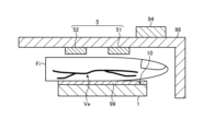
- FIG. 2 is a schematic diagram showing the positional relationship between the sensor module, the light source unit, and their peripheral configuration, and the blood vessels of a finger that are the object to be detected by the sensor module.
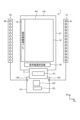
- FIG. 3 is a plan view showing an example of a sensor module, a light source unit, and a configuration connected thereto.
- FIG. 4 is a block diagram showing a more detailed example of the functional configuration of the configuration shown in FIG.
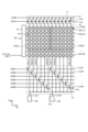
- FIG. 5 is a circuit diagram showing the sensor module.
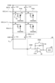
- FIG. 6 is a circuit diagram showing a plurality of partial detection regions.
- FIG. 7 is a schematic diagram showing the relationship between the degree of pressure applied from a finger to the sensor section and the sensing result by the sensor section.
- the detection device 100 includes a sensor module 1, a light source unit 5, an AFE 91, a control unit 92, a storage unit 93, a notification unit 94, and a communication unit 95.
- the sensor module 1 is provided so as to be able to detect light.
- the light source unit 5 is a light source that emits light of a wavelength that can be detected by the sensor module 1.
- the AFE 91 denotes an analog front end.
- the light source unit 5 has, for example, a first light source substrate 51 and a second light source substrate 52.
- the specific configuration example of the light source unit 5 shown in FIG. 2 is merely an example and is not limited thereto, and may have, for example, either the first light source substrate 51 or the second light source substrate 52 and a light source provided on that one, or may have three or more light source substrates and light sources provided on the light source substrates.
- a louver 99 is provided between the sensor module 1 and the finger Fi.
- the louver 99 is, for example, a light-shielding member provided with a plurality of light-guiding holes penetrating in the opposing direction between the finger Fi and the sensor unit 10, and acts to limit the direction of travel of light passing between the finger Fi and the sensor unit 10 to the opposing direction between the finger Fi and the sensor unit 10.
- the light source unit 5 is supported by a light-shielding member 98 on the opposite side of the sensor unit 10 with the finger Fi between them.
- the light-shielding member 98 is a cover-like member that covers the detection surface of the sensor unit 10 so that light other than the light emitted from the light source unit 5 does not enter the sensor unit 10.
- the light source unit 5 is provided on the sensor unit 10 side (one side) of the light-shielding member 98.
- a notification unit 94 is provided on the light-shielding member 98.
- the notification unit 94 is provided on the other side of the light-shielding member 98. To a user who inserts his finger Fi between the light source unit 5 and the sensor unit 10, the notification unit 94 appears to be provided on the light-shielding member 98.
- the sensor module 1 and light source unit 5 are described below with reference to Figures 3 to 6.
- FIG. 3 is a plan view showing an example of the sensor module 1 and the light source unit 5, as well as a configuration connected thereto.
- the sensor module 1 has a sensor substrate 21, a sensor unit 10, a gate line driving circuit 15, a signal line selection circuit 16, an AFE 91, a control circuit 122, a power supply circuit 123, a first light source substrate 51, a second light source substrate 52, at least one first light source 61, and at least one second light source 62.
- first light source 61 and second light source 62 are exemplified as the light source in the embodiment, there may be only one type of light source.
- the sensor substrate 21 has a detection area AA and a peripheral area GA.
- the detection area AA is an area in which multiple photodiodes PD (see FIG. 6) of the sensor unit 10 are provided.
- the peripheral area GA is an area between the outer periphery of the detection area AA and the end of the sensor substrate 21, and is an area that does not overlap with the photodiodes PD.
- the gate line driving circuit 15 and the signal line selection circuit 16 are provided in the peripheral area GA. Specifically, the gate line driving circuit 15 is provided in a region of the peripheral area GA that extends along the second direction Dy. The signal line selection circuit 16 is provided in a region of the peripheral area GA that extends along the first direction Dx, and is provided between the sensor unit 10 and the AFE 91.
- the first direction Dx is a direction in a plane parallel to the sensor substrate 21.
- the second direction Dy is a direction in a plane parallel to the sensor substrate 21, and is a direction perpendicular to the first direction Dx.
- the second direction Dy may intersect the first direction Dx without being perpendicular to it.
- the third direction Dz is a direction perpendicular to the first direction Dx and the second direction Dy, and is a normal direction of the sensor substrate 21.
- the multiple first light sources 61 are provided on the first light source substrate 51 and are arranged along the second direction Dy.
- the multiple second light sources 62 are provided on the second light source substrate 52 and are arranged along the second direction Dy.
- the first light source substrate 51 and the second light source substrate 52 are electrically connected to the control circuit 122 and the power supply circuit 123 via terminal portions 124 and 125, respectively, provided on the control board 121.
- the first light sources 61 and the second light sources 62 are, for example, inorganic light emitting diodes (LEDs) or organic light emitting diodes (OLEDs).
- the first light sources 61 and the second light sources 62 emit first light L61 (see FIG. 38) and second light L62 (see FIG. 31, etc.) of different wavelengths.
- the first light L61 and the second light L62 have different maximum emission wavelengths.
- the maximum emission wavelength is the wavelength that shows the maximum emission intensity in the emission spectrum that shows the relationship between the wavelength and emission intensity of each of the first light L61 and the second light L62.
- the numerical value of the wavelength is simply stated, it is assumed to indicate the assumed maximum emission wavelength.
- the first light L61 emitted from the first light source 61 is mainly reflected by the surface of the object to be detected, such as a finger Fg, and enters the sensor unit 10. This allows the sensor unit 10 to detect a fingerprint by detecting the uneven shape of the surface of the finger Fg.
- the second light L62 emitted from the second light source 62 is mainly reflected inside the finger Fg or passes through the finger Fg and enters the sensor unit 10. This allows the sensor unit 10 to detect information about the living body inside the finger Fg.
- Information about the living body includes, for example, the pulse waves, pulse, and blood vessel images of the finger Fg or palm.
- the first light L61 may have a wavelength of 520 nm or more and 600 nm or less
- the second light L62 may have a wavelength of 780 nm or more and 900 nm or less, for example, about 850 nm.
- the first light L61 is blue or green visible light
- the second light L62 is infrared light.
- the sensor unit 10 can detect a fingerprint based on the first light L61 emitted from the first light source 61.
- the second light L62 emitted from the second light source 62 is reflected inside the detection object such as a finger Fg or transmitted and absorbed by the finger Fg or the like and enters the sensor unit 10. This allows the sensor unit 10 to detect a pulse wave or a blood vessel image (blood vessel pattern) as information about the living body inside the finger Fg or the like.
- the first light L61 may have a wavelength of 600 nm or more and 700 nm or less, for example, about 660 nm
- the second light L62 may have a wavelength of 780 nm or more and 900 nm or less, for example, about 850 nm.
- the sensor unit 10 can detect information about the living body, such as pulse waves, pulse, and blood vessel images, as well as blood oxygen saturation.
- the detection device 100 since the detection device 100 has the first light source 61 and multiple second light sources 62, it can detect various information about the living body by performing detection based on the first light L61 and detection based on the second light L62.
- the arrangement of the first light source 61 and the second light source 62 shown in FIG. 3 is merely an example and can be changed as appropriate.
- a plurality of first light sources 61 and a plurality of second light sources 62 may be arranged on each of the first light source substrate 51 and the second light source substrate 52.
- a group including a plurality of first light sources 61 and a group including a plurality of second light sources 62 may be arranged side by side in the second direction Dy, or the first light sources 61 and the second light sources 62 may be arranged alternately in the second direction Dy.
- the number of light source substrates on which the first light source 61 and the second light source 62 are provided may be one or three or more.
- either the first light source 61 or the second light source 62 may be provided.
- a light source that emits light including infrared rays is provided.
- the infrared rays are infrared rays with a wavelength closer to visible light, so-called near-infrared rays.
- FIG. 4 is a block diagram showing a more detailed example of the functional configuration of the configuration shown in FIG. 3.
- the sensor module 1 further has a detection control unit 11 and a detection unit 40. Some or all of the functions of the detection control unit 11 are included in the control circuit 122. In addition, some or all of the functions of the detection unit 40 other than the AFE 91 are included in the control circuit 122.
- the sensor unit 10 is an optical sensor having a photodiode PD, which is a photoelectric conversion element.
- the photodiode PD of the sensor unit 10 outputs an electrical signal corresponding to the irradiated light to the signal line selection circuit 16.
- the signal line selection circuit 16 sequentially selects the signal lines SGL according to the selection signal ASW from the detection control unit 11. As a result, the electrical signal is output to the detection unit 40 as the detection signal Vdet.
- the sensor unit 10 also performs detection according to the gate drive signal Vgcl supplied from the gate line drive circuit 15.
- the detection control unit 11 is a circuit that supplies control signals to the gate line driving circuit 15, the signal line selection circuit 16, and the detection unit 40, respectively, and controls their operation.
- the detection control unit 11 supplies various control signals, such as a start signal STV, a clock signal CK, and a reset signal RST1, to the gate line driving circuit 15.
- the detection control unit 11 also supplies various control signals, such as a selection signal ASW, to the signal line selection circuit 16.
- the detection control unit 11 also supplies various control signals to the first light source 61 and the second light source 62, and controls the lighting and non-lighting of each.
- the signal line selection circuit 16 is a switch circuit that sequentially or simultaneously selects multiple signal lines SGL (see FIG. 5).
- the signal line selection circuit 16 is, for example, a multiplexer.
- the signal line selection circuit 16 connects the selected signal line SGL to the AFE 91 based on a selection signal ASW supplied from the detection control unit 11. As a result, the signal line selection circuit 16 outputs the detection signal Vdet of the photodiode PD to the detection unit 40.
- the detection unit 40 includes an AFE 91, a signal processing unit 44, a storage unit 93, a detection timing control unit 47, and an output processing unit 50.
- the detection timing control unit 47 controls the AFE 91 and the signal processing unit 44 to operate in synchronization based on a control signal supplied from the detection control unit 11.
- the AFE 91 is, for example, a signal processing circuit having the functions of a detection signal amplifier 42 and an A/D converter 43.
- the detection signal amplifier 42 amplifies the detection signal Vdet.
- the A/D converter 43 converts the analog signal output from the detection signal amplifier 42 into a digital signal.
- the signal processing unit 44 is a logic circuit that detects a predetermined physical quantity input to the sensor unit 10 based on the output signal of the AFE 91.
- the signal processing unit 44 can detect the unevenness of the surface of the finger Fg or the palm based on the signal from the AFE 91.
- the signal processing unit 44 can also detect information about the living body based on the signal from the AFE 91.
- the information about the living body is, for example, the blood vessel image of the finger Fg or the palm, pulse wave, pulse rate, blood oxygen saturation, etc.
- the first light L61 When acquiring the blood oxygen saturation of a human, for example, 660 nm (this range is 500 nm to 700 nm) is adopted as the first light L61, and about 850 nm (this range is 800 nm to 930 nm) is adopted as the second light L62. Since the amount of light absorption changes depending on the amount of oxygen taken up by hemoglobin, the amount of light obtained by subtracting the light absorbed by blood (hemoglobin) from the irradiated first light L61 and second light L62 is detected by the photodiode PD. Most of the oxygen in blood is reversibly bound to hemoglobin in red blood cells, and only a small portion is dissolved in plasma.
- oxygen saturation SpO 2
- the value of what percentage of the allowable amount of oxygen is bound to the blood as a whole is called oxygen saturation (SpO 2 ).
- the signal processing unit 44 may also acquire detection signals Vdet (information about the living body) simultaneously detected by multiple photodiodes PD and perform a process of averaging these.
- the detection unit 40 can suppress measurement errors caused by noise and relative positional deviation between the sensor unit 10 and the detected object such as a finger Fg, enabling stable detection.
- the memory unit 93 temporarily stores the signal calculated by the signal processing unit 44.
- the memory unit 93 may be, for example, a RAM (Random Access Memory), a register circuit, etc.
- the output processing unit 50 functions as a processing unit that performs processing based on the outputs from the multiple photodiodes PD. Specifically, the output processing unit 50 of the embodiment outputs a sensor output Vo that includes at least pulse wave data based on at least the detection signal Vdet acquired via the signal processing unit 44. In the embodiment, the signal processing unit 44 outputs data indicating the change (amplitude) in the output of the detection signal Vdet of each photodiode PD described below, and the output processing unit 50 decides which output is to be adopted as the sensor output Vo, but both may be performed by the signal processing unit 44 or the output processing unit 50.
- the signal processing unit 44 may be provided with a noise filter as necessary.
- the frequency components of noise caused by breathing and changes in posture are, for example, 1 Hz or less, which is a sufficiently lower frequency than the frequency components of the pulse wave, and can be removed by using a bandpass filter as a noise filter.
- the bandpass filter can be provided, for example, in the detection signal amplifier unit 42.
- the frequency components of noise caused by human body movements, etc. are, for example, several Hz to 100 Hz, and may overlap with the frequency components of the pulse wave.
- the frequency is not a constant frequency but has frequency fluctuations, so a noise filter is used to remove frequencies with fluctuation components.
- a noise filter is used to remove frequencies with fluctuation components.
- first fluctuation component removal method the property that a time lag occurs in the peak value of a pulse wave depending on the measurement location on the human body may be used.
- a time lag occurs in the pulse wave depending on the measurement location on the human body, and noise caused by human body movements, etc. does not have a time lag or has a smaller time lag than the pulse wave. Therefore, the pulse wave is measured at at least two different locations, and if the peak values measured at the different locations are within a predetermined time, they are removed as noise.
- the waveform due to noise and the waveform due to the pulse wave overlap by chance, but in this case, the two waveforms overlap only at one of the different locations, making it possible to distinguish between the waveform due to noise and the waveform due to the pulse wave.
- This process can be performed, for example, by the signal processing unit 44.
- a method for removing frequencies having fluctuation components (second fluctuation component removal method)
- frequency components with different phases are removed by the signal processing unit 44.
- a short-time Fourier transform may be performed to remove the fluctuation components, and an inverse Fourier transform may be performed.
- noise sources 50 Hz, 60 Hz
- noise caused by commercial frequency power sources may be removed by providing a shield on the surface opposite to the detection surface of the detector.
- FIG. 5 is a circuit diagram showing the sensor unit 10.
- FIG. 6 is a circuit diagram showing a plurality of partial detection areas. Note that FIG. 6 also shows the circuit configuration of the AFE 91.
- the sensor unit 10 has a plurality of partial detection areas PAA arranged in a matrix. Each of the partial detection areas PAA is provided with a photodiode PD.
- the gate line GCL extends in the first direction Dx and is connected to a plurality of partial detection areas PAA arranged in the first direction Dx.
- the plurality of gate lines GCL(1), GCL(2), ..., GCL(8) are arranged in the second direction Dy and are each connected to the gate line driving circuit 15.
- gate lines GCL when there is no need to distinguish between the plurality of gate lines GCL(1), GCL(2), ..., GCL(8), they are simply referred to as gate lines GCL.
- the signal line SGL extends in the second direction Dy and is connected to the photodiodes PD of the multiple partial detection areas PAA arranged in the second direction Dy.
- the multiple signal lines SGL(1), SGL(2), ..., SGL(12) are arranged in the first direction Dx and are each connected to the signal line selection circuit 16 and the reset circuit 17. In the following description, when it is not necessary to distinguish between the multiple signal lines SGL(1), SGL(2), ..., SGL(12), they will simply be referred to as signal lines SGL.
- the resolution of the sensor is, for example, 508 dpi (dots per inch), and the number of cells is 252 ⁇ 256.
- the sensor unit 10 is provided between the signal line selection circuit 16 and the reset circuit 17. This is not limited, and the signal line selection circuit 16 and the reset circuit 17 may be connected to the ends of the signal lines SGL in the same direction.
- the substantial area of one sensor is, for example, substantially 50 ⁇ 50 ⁇ m 2
- the area of the detection area AA is, for example, 12.6 ⁇ 12.8 mm 2 .
- the gate line driving circuit 15 receives various control signals, such as a start signal STV, a clock signal CK, and a reset signal RST1, from the control circuit 122 (see FIG. 3). Based on the various control signals, the gate line driving circuit 15 sequentially selects multiple gate lines GCL(1), GCL(2), ..., GCL(8) in a time-division multiplexing manner. The gate line driving circuit 15 supplies a gate driving signal Vgcl to the selected gate line GCL. As a result, the gate driving signal Vgcl is supplied to multiple first switching elements Tr connected to the gate line GCL, and multiple partial detection areas PAA arranged in the first direction Dx are selected as detection targets.
- various control signals such as a start signal STV, a clock signal CK, and a reset signal RST1
- the gate line driving circuit 15 may perform different driving for each detection mode of fingerprint detection and information related to a plurality of different biological bodies (pulse wave, pulse, blood vessel image, blood oxygen saturation, etc.). For example, the gate line driving circuit 15 may drive a bundle of multiple gate lines GCL.
- the gate line driving circuit 15 may simultaneously select a predetermined number of gate lines GCL from the gate lines GCL(1), GCL(2), ..., GCL(8) based on the control signal. For example, the gate line driving circuit 15 simultaneously selects the six gate lines GCL(1) to GCL(6) and supplies the gate driving signal Vgcl. The gate line driving circuit 15 supplies the gate driving signal Vgcl to the first switching elements Tr via the six selected gate lines GCL. As a result, group areas PAG1 and PAG2 including a plurality of partial detection areas PAA arranged in the first direction Dx and the second direction Dy are selected as detection targets.
- the gate line driving circuit 15 drives a predetermined number of gate lines GCL in a bundle and sequentially supplies the gate driving signal Vgcl to each of the predetermined number of gate lines GCL.
- group areas PAG when the positions of the different group areas such as the group areas PAG1 and PAG2 are not particularly distinguished, they will be referred to as group areas PAG.
- the signal line selection circuit 16 has a plurality of selection signal lines Lsel, a plurality of output signal lines Lout, and a third switching element TrS.
- the plurality of third switching elements TrS are provided corresponding to the plurality of signal lines SGL, respectively.
- the six signal lines SGL(1), SGL(2), ..., SGL(6) are connected to a common output signal line Lout1.
- the six signal lines SGL(7), SGL(8), ..., SGL(12) are connected to a common output signal line Lout2.
- the output signal lines Lout1, Lout2 are each connected to the AFE 91.
- the signal lines SGL(1), SGL(2), ..., SGL(6) are defined as a first signal line block
- the signal lines SGL(7), SGL(8), ..., SGL(12) are defined as a second signal line block.
- the multiple selection signal lines Lsel are each connected to the gate of the third switching element TrS included in one signal line block. Furthermore, one selection signal line Lsel is connected to the gate of the third switching element TrS of multiple signal line blocks.
- the selection signal lines Lsel1, Lsel2, ..., Lsel6 are connected to the third switching elements TrS corresponding to the signal lines SGL(1), SGL(2), ..., SGL(6), respectively.
- the selection signal line Lsel1 is connected to the third switching element TrS corresponding to the signal line SGL(1) and the third switching element TrS corresponding to the signal line SGL(7).
- the selection signal line Lsel2 is connected to the third switching element TrS corresponding to the signal line SGL(2) and the third switching element TrS corresponding to the signal line SGL(8).
- the control circuit 122 (see FIG. 3) sequentially supplies the selection signal ASW to the selection signal line Lsel.
- the signal line selection circuit 16 sequentially selects the signal lines SGL in one signal line block in a time-division manner through the operation of the third switching element TrS.
- the signal line selection circuit 16 also selects one signal line SGL each in each of the multiple signal line blocks.
- the signal line selection circuit 16 may bundle multiple signal lines SGL and connect them to the AFE 91.
- the control circuit 122 (see FIG. 3) simultaneously supplies the selection signal ASW to the selection signal lines Lsel.
- the signal line selection circuit 16 selects multiple signal lines SGL (e.g., six signal lines SGL) in one signal line block by the operation of the third switching element TrS, and connects the multiple signal lines SGL to the AFE 91.
- signals detected in each group area PAG are output to the AFE 91.
- signals from multiple partial detection areas PAA (photodiodes PD) are integrated in group area PAG units and output to the AFE 91.
- the sensor module 1 can repeatedly perform detection in a short period of time, improving the S/N ratio and enabling accurate detection of temporal changes in information related to a living body, such as pulse waves.
- the reset circuit 17 has a reference signal line Lvr, a reset signal line Lrst, and a fourth switching element TrR.
- the fourth switching element TrR is provided corresponding to the multiple signal lines SGL.
- the reference signal line Lvr is connected to one of the sources or drains of the multiple fourth switching elements TrR.
- the reset signal line Lrst is connected to the gates of the multiple fourth switching elements TrR.
- the control circuit 122 supplies a reset signal RST2 to the reset signal line Lrst. This turns on the multiple fourth switching elements TrR, and the multiple signal lines SGL are electrically connected to the reference signal line Lvr.
- the power supply circuit 123 supplies a reference signal COM to the reference signal line Lvr. This causes the reference signal COM to be supplied to the capacitive elements Ca (see FIG. 6) included in the multiple partial detection areas PAA.
- the partial detection area PAA includes a photodiode PD, a capacitance element Ca, and a first switching element Tr.
- a photodiode PD two gate lines GCL(m) and GCL(m+1) arranged in the second direction Dy among the multiple gate lines GCL are shown.
- the partial detection area PAA is an area surrounded by the gate lines GCL and the signal lines SGL.
- the first switching element Tr is provided corresponding to the photodiode PD.
- the first switching element Tr is composed of a thin film transistor, and in this example, is composed of an n-channel MOS (Metal Oxide Semiconductor) type TFT (Thin Film Transistor).
- MOS Metal Oxide Semiconductor
- the gates of the first switching elements Tr belonging to the multiple partial detection areas PAA aligned in the first direction Dx are connected to the gate line GCL.
- the sources of the first switching elements Tr belonging to the multiple partial detection areas PAA aligned in the second direction Dy are connected to the signal line SGL.
- the drains of the first switching elements Tr are connected to the cathodes of the photodiodes PD and the capacitance elements Ca.
- the anode of the photodiode PD is supplied with a sensor power supply signal VDDSNS from the power supply circuit 123.
- the signal line SGL and the capacitance element Ca are supplied with a reference signal COM, which is the initial potential of the signal line SGL and the capacitance element Ca, from the power supply circuit 123.
- the AFE 91 functions as at least the A/D converter 43, converting an analog signal output from the sensor unit 10 into a digital signal and outputting it to the controller 92.
- the AFE 91 may also function as the detection signal amplifier 42.
- the digital signal is a signal that can be interpreted by a calculation circuit provided in the controller 92 and functioning as the signal processor 44.
- the AFE 91 also outputs a signal for controlling the illumination of the first light source 61 and the second light source 62 under the control of the controller 92.
- the controller 92 in the embodiment in which the configuration described with reference to FIGS. 3 to 6 is applied includes the signal processor 44, the detection timing controller 47, and the output processor 50.
- the AFE 91 and the control unit 92 each have one or more circuits implemented to realize the functions described above. Such circuits may be circuits that integrate multiple functions, or may be circuits that are provided separately for each function.
- the notification unit 94 has a light source that turns on or off in response to the result of a determination regarding the degree of pressure applied from the finger Fi to the sensor unit 10.
- the light source is, for example, an LED or OLED, but is not limited to this and may be another specific configuration that functions in a similar manner. The determination and the operation of the notification unit 94 will be described in detail later.
- the communication unit 95 performs processing related to communication with external devices.
- the communication unit 95 has a circuit to function as a NIC (Network Interface Controller) and performs processing related to communication with external devices according to a predetermined protocol.
- the communication path used for such communication may be a wired, wireless, or mixed wired and wireless line path, and may include a public communication network such as the Internet as part of it.
- control unit 92, the storage unit 93, and the communication unit 95 are integrated into the control circuit 122, but the specific implementation form is arbitrary.
- control unit 92, the storage unit 93, and the communication unit 95 may be provided as independent circuits.
- FIG. 7 is a schematic diagram showing the relationship between the degree of pressure applied from the finger Fi to the sensor unit 10 and the sensing result by the sensor module 1.
- the sensing result here refers to the light and dark pattern of the detection area obtained by the multiple photodiodes PD arranged in the detection area individually detecting light.
- the blood vessels Ve are assumed to be veins, but may also be arteries.
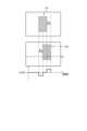
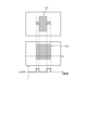
- the sensor module 1 of the embodiment can identify blood vessels Ve in the finger Fi depending on the distance from the finger Fi, even when the object to be detected (finger Fi) is not in contact with the louver 99. Specifically, as shown in “Pattern 1" in FIG. 7, when the distance between the louver 99 and the finger Fi is distance D1, a sensing result Sd1 is obtained in which there is no shadow of light corresponding to the finger Fi, i.e., no dark area in the sensing result. Note that, as shown in "Pattern 1", the presence of the louver 99 does not substantially cause a shadow in the sensing result.
- the sensing result when simply referred to as a dark area, it refers to a dark area in the sensing result that is caused by a shadow cast by the finger Fi blocking the light emitted from the light source unit 5 toward the sensor unit 10.
- the white area surrounding the dark area in the sensing result is a bright area that is caused by the light emitted from the light source unit 5 toward the sensor unit 10 being detected almost as is. Therefore, it can be said that the sensing result shows a light and dark pattern that is either a state of only bright areas, a state of only dark areas, or a state in which bright and dark areas are mixed.
- a sensing result Sd4 is obtained in which the dark areas corresponding to the finger Fi are darker than in the sensing result Sd3.
- the pattern of the blood vessels Ve in the sensing result Sd4 can be confirmed, for example, within the area Fa2.
- Pattern 1 to “Pattern 5" in FIG. 7 can also be seen as examples of the transition from a state in which the finger Fi is separated from the louver 99 to a state in which the finger Fi is pressed against the louver 99.
- the sensing results transition as in sensing results Sd1, Sd2, Sd3, Sd4, and Sd5, and the dark areas included in the sensing results gradually expand with each transition.
- the change in the range occupied by the dark area in the sensing result may also include movement due to positional deviation of the finger Fi. Whether the change in the range occupied by the dark area in the sensing result corresponds to movement or enlargement can be identified based on a comparison of the sensing results before and after the transition.
- FIG. 8 is a schematic diagram showing a case where a change in the range occupied by dark areas in the sensing results corresponds to movement.
- the dark area included in the sensing result from the sensing performed at a relatively earlier timing is designated as dark area Si1.
- dark area Si2 the dark area included in the sensing result from the sensing performed at a relatively later timing.
- the dark areas Si1 and Si2 shown in FIG. 8 are positioned differently in the first direction Dx.
- the difference between the presence and absence of dark areas in the first direction Dx is shown in a graph to show the change in the range occupied by the dark areas in the sensing results.
- the horizontal axis represents the coordinate (x-coordinate) in the first direction Dx
- the vertical axis represents the output of the sensing results acquired by the AFE91 from the sensor module 1.
- the dark areas are increasing relatively in the later sensing results, this is treated as a positive output
- the dark areas are decreasing relatively in the later sensing results, this is treated as a negative output in the vertical direction.
- the sensing result at one timing is considered to be the sensing result of "one frame," when a dark area that appears in the sensing result of a relatively later frame among two or more different timings is larger than a dark area that appears in the sensing result of a relatively earlier frame, it can be considered that the pressure from the detected object (e.g., a finger Fi) that creates the dark area toward the detection area of the sensor unit 10 has increased during the multiple timings.
- the detected object in question can be considered to be a finger Fi.
- FIG. 9 is a schematic diagram showing a case where the change in the range occupied by the dark area in the sensing result corresponds to an enlargement.
- the dark area included in the sensing result from sensing performed at a relatively later timing is designated as dark area Si3.
- the change in the dark area in the sensing result i.e., the reduction in the dark area
- the change in the dark area in the sensing result is considered to be due to a change in the relative distance between the finger Fi and the sensor unit 10 (increasing distance) or a decrease in the pressure from the finger Fi toward the sensor unit 10.
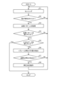
- FIG. 10 is a flowchart showing the process flow of the detection device 100, including the determination and notification that the pressure from the finger Fi toward the sensor unit 10 is too strong.
- sensing is performed (step S1). Specifically, the photodiode PD of the sensor module 1 operates, and an output is generated according to the intensity of the light emitted from the light source unit 5 and detected by the photodiode PD. This output is processed by the AFE 91 and the control unit 92, and becomes data that can be interpreted as a sensing result as described with reference to FIGS. 7 and 8.
- the control unit 92 judges whether a finger is detected by the sensing process of step S1 (step S2). Specifically, the control unit 92 performs a judgment process to judge whether the sensing result obtained by the process of step S1 includes a dark area that can be judged to have been caused by the finger Fi.
- the judgment process includes a number of judgments, such as whether a dark area has been generated, whether the ratio of the dark area to the entire sensing result is an appropriate ratio that can be interpreted as a dark area caused by the finger Fi if a dark area has been generated, and whether the shape of the dark area is an appropriate shape that can be interpreted as a dark area caused by the finger Fi if a dark area has been generated, but the specific content can be changed as appropriate.
- a range of the ratio that can be considered as an appropriate ratio that can be interpreted as a dark area caused by the finger Fi is determined in advance based on a prior test or the like, and is held by the control unit 92.
- whether the shape of the dark area can be interpreted as a dark area caused by a finger Fi is determined based on, for example, pattern matching with sample data of dark areas caused by a finger Fi that has been prepared in advance, and when such pattern matching is used, the sample data is stored in the control unit 92 or a storage device that can be referenced by the control unit 92 and is provided in the detection device 100.
- step S2 If it is determined in step S2 that a finger has not been detected (step S2; No), the process proceeds to step S1. That is, sensing is performed again. On the other hand, if it is determined in step S2 that a finger has been detected (step S2; Yes), the control unit 92 performs a process of acquiring a pattern of the blood vessels Ve from the sensing results obtained in step S1 (step S3).
- the process of acquiring the pattern of the blood vessels Ve is based on, for example, the contrast between the blood vessels Ve and the area other than the blood vessels Ve in the dark area created by the finger Fi, and pattern matching with the shape of the area determined to be possibly a blood vessel Ve based on the contrast, but the specific content can be changed as appropriate.
- the sample data is stored in the control unit 92 or a storage device that can be referenced by the control unit 92 and is provided in the detection device 100.
- step S5 determines whether sufficient data corresponding to the purpose of the predetermined process has been obtained.
- the predetermined process is a "personal authentication process based on the blood vessel pattern”. In this case, it is sufficient that one or more patterns of the blood vessel Ve that can be compared with the blood vessel pattern prepared in advance are obtained in the process of step S3.
- the predetermined process is a "pulse measurement process”. In this case, it is sufficient that multiple sensing results are obtained in a predetermined cycle.
- step S5 makes it possible to calculate the pulse from the relationship between the pulsation indicated by the patterns of the multiple blood vessels Ve and the time length of the predetermined cycle. Even in the case of processes other than those exemplified here, the result of the process of step S5 corresponds to the specific content of the predetermined process.
- step S5 If it is determined in step S5 that sufficient data according to the purpose has been obtained in the predetermined process (step S5; Yes), the process by the detection device 100 ends. On the other hand, if it is determined in step S5 that sufficient data according to the purpose has not been obtained in the predetermined process (step S5; No), difference extraction is performed in n-frame units (step S6). Specifically, after the process starts, of the sensing results obtained in step S1 that has already been performed up to the process of step S6, the most recent n sensing results (n is a natural number equal to or greater than 2) are extracted as targets for the process of step S7 described below. Note that if the number of times that step S1 has already been performed up to the process of step S6 is less than n, all sensing results are extracted as targets for the process of step S7.
- the control unit 92 determines whether there is excessive pressure from the finger Fi toward the sensor unit 10 (step S7). Specifically, the control unit 92 compares the sensing results obtained in later sensing with earlier sensing results among the sensing results extracted in the processing of step S6. If the result of such comparison indicates that the pattern of the blood vessel Ve is unclear or has disappeared in the sensing result obtained in the later sensing compared to the earlier sensing result, the control unit 92 determines that there is excessive pressure from the finger Fi toward the sensor unit 10 to the extent that the above-mentioned crushing Cr occurs.
- control unit 92 may determine that the cause of the disappearance of the pattern of the blood vessel Ve in the sensing result obtained in the later sensing is not due to the movement of the finger Fi from the earlier sensing result, using a concept similar to that described with reference to FIG. 8. Conversely, if the finger Fi has moved, and the pattern of blood vessels Ve in the finger Fi that was generated in the previous sensing result is generated at a position corresponding to the finger Fi after the movement, it is deemed that there is no excessive pressure from the finger Fi toward the sensor unit 10.
- step S7 determines that there is excessive pressure from the finger Fi towards the sensor unit 10 (step S7; Yes)
- the detection device 100 performs a pressure response operation (step S8).
- the control unit 92 turns on the notification unit 94.
- the notification unit 94 it is possible to notify a person who can see the notification unit 94, such as a user who is pressing the finger Fi against the sensor unit 10, that excessive pressure from the finger Fi is occurring towards the sensor unit 10.
- the notification unit 94 functions as a component for notifying that excessive pressure from the finger Fi is occurring towards the sensor unit 10.
- step S8 After the processing of step S8 or in the processing of step S7, if it is determined that there is no excessive pressure from the finger Fi toward the sensor unit 10 (step S7; No), the processing proceeds to step S1.
- step S2 can be omitted. That is, after the processing of step S1, the process may automatically proceed to the processing of step S3.
- the control unit 92 may determine that the finger Fi has been detected when the pattern of the blood vessel Ve is obtained in the processing of step S4 (step S4; Yes). That is, the processing of step S4 may also serve as the processing of step S2.
- the lighting of the notification unit 94 is not limited to the processing of step S8.
- the notification unit 94 may be configured to light up in the first pattern when the pattern of the blood vessel Ve is obtained in the processing of step S4 (step S4; Yes), and to light up in the second pattern when the processing of step S8 is performed.
- the first pattern indicates that the pattern of the blood vessel Ve has been obtained normally.
- the second pattern indicates that the pressing force from the finger Fi to the sensor unit 10 side is too strong.
- the first pattern and the second pattern are different lighting patterns, but how they are made different is arbitrary.
- the color of the light source that is turned on in the first pattern may be different from the color of the light source that is turned on in the second pattern.
- the lighting state according to the first pattern and the lighting state according to the second pattern may be different.
- the light source continues to light up in the first pattern, and the light source repeatedly flashes in the second pattern.
- the detection device includes a sensor unit (sensor unit 10) having a plurality of optical sensors (photodiodes PD) arranged two-dimensionally, and an acquisition unit (control unit 92) that acquires the pattern of blood vessels (blood vessels Ve) of a human finger (finger Fi) contained in the light and dark pattern detected by the sensor unit, and the acquisition unit acquires information regarding the pressure from the finger toward the sensor unit based on the light and dark pattern. Therefore, according to the embodiment, the pressure can be detected based on the light and dark pattern without providing a dedicated pressure sensor for detecting the pressure.
- the acquisition unit determines that the pressure from the finger (finger Fi) has increased during acquisition of the multiple light and dark patterns. This makes it possible to detect whether the pressure has increased based on whether the size of the dark areas included in the light and dark patterns has increased.
- the acquisition unit determines that the pressure from the finger (finger Fi) was too strong when the relatively later light and dark pattern was obtained. This makes it possible to detect that the pressure is too strong based on the blood vessel pattern contained in the light and dark patterns.
- the detection device also includes a notification unit (notification unit 94) that notifies the user of the pressure from the finger (finger Fi) to the sensor unit (sensor unit 10). This makes it possible to notify information about the pressure to a person who can receive a notification from the notification unit, such as a user who is pressing the finger (finger Fi) against the sensor unit.
- a notification unit notification unit 94
- the device also has a light source (second light source 62) that is disposed opposite the surface on which the multiple optical sensors (photodiodes PD) are arranged and emits light that includes at least one of visible light and infrared light. This makes it easier and more reliable for the finger (finger Fi) to create dark areas on the surface.
- a light source (second light source 62) that is disposed opposite the surface on which the multiple optical sensors (photodiodes PD) are arranged and emits light that includes at least one of visible light and infrared light. This makes it easier and more reliable for the finger (finger Fi) to create dark areas on the surface.
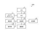
- FIG. 11 is a block diagram showing an example of the main configuration of a detection device 100A according to a modified example.
- the detection device 100A further includes an operating unit 96.
- the operating unit 96 is provided so as to be switchable between a state in which it protrudes toward the finger Fi and a state in which it does not protrude toward the finger Fi, based on the closest position of the finger Fi to the sensor unit 10.
- the "closest position of the finger Fi to the sensor unit 10" is, for example, the position BL of the surface of the louver 99 on the finger Fi side.
- the finger Fi when the finger Fi abuts against the surface of the louver 99 on the finger Fi side, the finger Fi is considered to be closest to the sensor unit 10.
- the "closest position of the finger Fi to the sensor unit 10" is the surface on which the multiple photodiodes PD are provided in the sensor unit 10, i.e., the surface of the detection area.
- the operating unit 96 drives the operating unit to push up the finger Fi.
- the pressing force of the finger Fi is too high, it is, for example, the case of pattern 5 described with reference to FIG. 7, and in such a case, the pressing force of the finger Fi is deemed to be too high (above a predetermined value).
- which part of the eccentric cam is on the "closest position of the finger Fi to the sensor unit 10" side changes depending on the rotation angle of the rotation shaft.
- the operating unit 96 is arranged so that both a rotation angle of the rotation shaft at which a part of the outer circumferential surface of the eccentric cam protrudes toward the finger Fi from the "closest position of the finger Fi to the sensor unit 10" and a rotation angle of the rotation shaft at which the eccentric cam does not protrude toward the finger Fi from the "closest position of the finger Fi to the sensor unit 10" are generated.
- this example is merely one example of a specific configuration of the operating unit 96 and is not limited to this.
- the operating unit 96 may be an operating mechanism that is configured to be able to switch between protruding and not protruding toward the finger Fi from the "closest position of the finger Fi to the sensor unit 10" by linear motion of an actuator.
- the operating unit 96 only needs to be configured to be able to switch between protruding and not protruding toward the finger Fi based on the "closest position of the finger Fi to the sensor unit 10", and the specific configuration is not limited to this.
- the operating unit 96 operates to protrude toward the finger Fi from the "closest position of the finger Fi to the sensor unit 10" when the pressing force from the finger Fi is deemed to be too strong.
- the control unit 92 operates the operating unit 96 to protrude toward the finger Fi from the "closest position of the finger Fi to the sensor unit 10".
- the finger Fi is placed in a state in which it receives a biasing force from the operating unit 96 in a direction away from the "closest position of the finger Fi to the sensor unit 10".
- the operation of the operating unit 96 is intended to suggest to the user of the finger Fi through the tactile contact with the operating unit 96 that the pressing force toward the "closest position of the finger Fi to the sensor unit 10" is to be reduced.
- the user of the finger Fi can easily realize that the pressing force applied from the finger Fi to the sensor unit 10 side is too strong.
- step S7 determines that there is no excessive pressure from the finger Fi towards the sensor unit 10 (step S7; No)
- the control unit 92 operates the operating unit 96 so that it does not protrude towards the finger Fi from the "closest position of the finger Fi to the sensor unit 10". This makes it easier for the user of the finger Fi to realize that the state in which the pressure applied from the finger Fi towards the sensor unit 10 is too strong has been resolved.
- lighting control of the notification unit 94 may also be performed as in the embodiment.
- the modified example is the same as the embodiment.
- an operating unit (operating unit 96) is provided adjacent to the sensor unit (sensor unit 10) and is switchable between a state in which it protrudes toward the finger and a state in which it does not protrude toward the finger in response to the pressure from the finger toward the sensor unit, based on the closest position (position BL) of the finger (finger Fi) to the sensor unit. This allows output according to the pressure to be generated via the operating unit.
- the operating unit (operating unit 96) also protrudes toward the finger when the pressure from the finger (finger Fi) is deemed to be too strong. This allows the operating unit to indicate to the user, who is pressing the finger (finger Fi) against the sensor unit (sensor unit 10), that the pressure is too strong, through the feeler sensations that the operating unit creates on the finger.
- the configuration that functions as the notification unit is not limited to the notification unit 94 and the operation unit 96, and the specific configuration can be changed as appropriate.
- a voice output device including a speaker that notifies the user by voice that the pressing force is too strong, an amplifier, and a storage device that stores voice data may be used as the notification unit.
- a display device that provides notifications by outputting images, such as images including text information, a display driver circuit, and a storage device that stores image data output by the display may be used as the notification unit.
- Reference Signs List 1 sensor module 5: light source unit 10: sensor unit 62: second light source 92: control unit 94: notification unit 96: operation unit 100, 100A: detection device Fi: finger Ve: blood vessel
Landscapes
- Health & Medical Sciences (AREA)
- Engineering & Computer Science (AREA)
- Life Sciences & Earth Sciences (AREA)
- Physics & Mathematics (AREA)
- General Health & Medical Sciences (AREA)
- Surgery (AREA)
- General Physics & Mathematics (AREA)
- Biomedical Technology (AREA)
- Public Health (AREA)
- Pathology (AREA)
- Veterinary Medicine (AREA)
- Heart & Thoracic Surgery (AREA)
- Medical Informatics (AREA)
- Molecular Biology (AREA)
- Animal Behavior & Ethology (AREA)
- Vascular Medicine (AREA)
- Biophysics (AREA)
- Theoretical Computer Science (AREA)
- Physiology (AREA)
- Cardiology (AREA)
- Human Computer Interaction (AREA)
- Multimedia (AREA)
- Business, Economics & Management (AREA)
- Emergency Management (AREA)
- Nuclear Medicine, Radiotherapy & Molecular Imaging (AREA)
- Oral & Maxillofacial Surgery (AREA)
- Computer Vision & Pattern Recognition (AREA)
- Measuring Pulse, Heart Rate, Blood Pressure Or Blood Flow (AREA)
- Measurement Of The Respiration, Hearing Ability, Form, And Blood Characteristics Of Living Organisms (AREA)
Abstract
検出装置は、二次元的に配置された複数の光センサを有するセンサ部と、センサ部によって検出された光の明暗パターンに含まれるヒトの指の血管のパターンを取得する取得部と、を備え、取得部は、明暗パターンに基づいて指からセンサ部に向かう押圧力に関する情報を取得する。
Description
本開示は、検出装置に関する。
ヒトの指を光センサに押し付けた状態で光センサによって光を検出することで、指の血管を検出する仕組みが知られている(例えば特許文献1)。
指の血管の検出では、光センサに対する指からの押圧力が強すぎると、血管の像が薄れてしまうことが知られている。このため、光センサに対する指からの押圧力が強すぎる場合、そのことを検出して光センサに指を押し付けているユーザにフィードバックすることが望ましい。しかしながら、従来の構成でそのようなフィードバックを実現するためには、まず光センサに対する指からの押圧力を検出するために専用の圧力センサを設ける必要があり、部品増加及びコスト増を招くという問題があった。
本開示は、上記の課題に鑑みてなされたもので、専用の圧力センサを設けることなく指からの押圧力に関する情報を取得可能な検出装置を提供することを目的とする。
本開示の一態様による検出装置は、二次元的に配置された複数の光センサを有するセンサ部と、前記センサ部によって検出された光の明暗パターンに含まれるヒトの指の血管のパターンを取得する取得部と、前記取得部は、前記明暗パターンに基づいて前記指から前記センサ部に向かう押圧力に関する情報を取得する。
以下に、本開示の各実施の形態について、図面を参照しつつ説明する。なお、開示はあくまで一例にすぎず、当業者において、発明の主旨を保っての適宜変更について容易に想到し得るものについては、当然に本開示の範囲に含有されるものである。また、図面は説明をより明確にするため、実際の態様に比べ、各部の幅、厚さ、形状等について模式的に表される場合があるが、あくまで一例であって、本開示の解釈を限定するものではない。また、本明細書と各図において、既出の図に関して前述したものと同様の要素には、同一の符号を付して、詳細な説明を適宜省略することがある。
(実施形態)
図1は、実施形態に係る検出装置100の主要構成例を示すブロック図である。検出装置100は、センサモジュール1、光源部5、AFE91、制御部92、記憶部93、報知部94及び通信部95を備える。センサモジュール1は、光を検出可能に設けられる。光源部5は、センサモジュール1で検出可能な波長の光を発する光源である。なお、符号91のAFEとは、アナログフロントエンド(Analog Front End)を示す。
図1は、実施形態に係る検出装置100の主要構成例を示すブロック図である。検出装置100は、センサモジュール1、光源部5、AFE91、制御部92、記憶部93、報知部94及び通信部95を備える。センサモジュール1は、光を検出可能に設けられる。光源部5は、センサモジュール1で検出可能な波長の光を発する光源である。なお、符号91のAFEとは、アナログフロントエンド(Analog Front End)を示す。
図2は、センサモジュール1、光源部5及びその周辺の構成と、センサモジュール1による被検出対象である指Fiの血管Veと、の位置関係を示す概略図である。図2に示すように、光源部5は、例えば第1光源基材51と第2光源基材52とを有する。図2に示す光源部5の具体的構成例はあくまで一例であってこれに限られるものでなく、例えば第1光源基材51又は第2光源基材52の一方と、当該一方に設けられる光源と、を有していてもよいし、3以上の光源基材と、係る光源基材に設けられる光源と、を有していてもよい。
センサモジュール1のセンサ部10は、指Fiを挟んで光源部5と対向する。光源部5に設けられた光源(例えば、後述する第1光源61、第2光源62)からの光は、一部が指Fi及び指Fi内の血管Veによって遮蔽、吸収されるが、遮蔽及び吸収されなかった光がセンサ部10に設けられたフォトダイオードPDによって検出される。ここで、血管Veと、指Fiのうち血管Ve以外の部分と、の間には、光の遮蔽、吸収の度合いに差がある。係る差が、血管Veと、指Fiのうち血管Ve以外の部分と、の間にコントラストを生じさせる。検出装置100は、係るコントラストをセンサモジュール1による光の検出で可視化することで、血管Veのパターン検出を可能としている。
なお、図2に示す例では、センサモジュール1と指Fiとの間にルーバー99が設けられている。ルーバー99は、例えば指Fiとセンサ部10との対向方向に貫通する複数の導光孔が設けられた遮光部材であり、指Fiとセンサ部10との間を通る光の進行方向を指Fiとセンサ部10との対向方向に限定するように作用する。
また、図2に示す例では、光源部5は、指Fiを挟んでセンサ部10の反対側で、遮光部材98によって支持されている。遮光部材98は、光源部5から発せられる光以外の光がセンサ部10に入射しないようセンサ部10の検出面を覆うカバー状の部材である。光源部5は、遮光部材98のセンサ部10側(一面側)に設けられる。また、図2に示す例では、報知部94が遮光部材98に設けられている。報知部94は、遮光部材98の他面側に設けられる。光源部5とセンサ部10との間に指Fiをさし入れるユーザからは、遮光部材98上に報知部94が設けられているように見える。
以下、センサモジュール1及び光源部5について、図3から図6を参照して説明する。
図3は、センサモジュール1及び光源部5ならびにこれらに接続される構成の一例を示す平面図である。図3に示すように、センサモジュール1は、センサ基材21と、センサ部10と、ゲート線駆動回路15と、信号線選択回路16と、AFE91と、制御回路122と、電源回路123と、第1光源基材51と、第2光源基材52と、少なくとも1つの第1光源61と、少なくとも1つの第2光源62と、を有する。なお、実施形態では、光源として複数種類の光源(第1光源61と第2光源62)を例示しているが、光源は1種類であってもよい。
センサ基材21には、フレキシブルプリント基板71を介して制御基板121が電気的に接続される。フレキシブルプリント基板71には、AFE91が設けられている。制御基板121には、制御回路122及び電源回路123が設けられている。制御回路122は、例えばFPGA(Field Programmable Gate Array)である。制御回路122は、センサ部10、ゲート線駆動回路15及び信号線選択回路16に制御信号を供給して、センサ部10の検出動作を制御する。また、制御回路122は、第1光源61及び第2光源62に制御信号を供給して、第1光源61及び第2光源62の点灯又は非点灯を制御する。電源回路123は、センサ電源信号VDDSNS(図6参照)等の電圧信号をセンサ部10、ゲート線駆動回路15及び信号線選択回路16に供給する。また、電源回路123は、AFE91の制御下で、電源電圧を第1光源61及び第2光源62に供給する。
センサ基材21は、検出領域AAと、周辺領域GAとを有する。検出領域AAは、センサ部10が有する複数のフォトダイオードPD(図6参照)が設けられた領域である。周辺領域GAは、検出領域AAの外周と、センサ基材21の端部との間の領域であり、フォトダイオードPDと重ならない領域である。
ゲート線駆動回路15及び信号線選択回路16は、周辺領域GAに設けられる。具体的には、ゲート線駆動回路15は、周辺領域GAのうち第2方向Dyに沿って延在する領域に設けられる。信号線選択回路16は、周辺領域GAのうち第1方向Dxに沿って延在する領域に設けられ、センサ部10とAFE91との間に設けられる。
なお、第1方向Dxは、センサ基材21と平行な面内の一方向である。第2方向Dyは、センサ基材21と平行な面内の一方向であり、第1方向Dxと直交する方向である。なお、第2方向Dyは、第1方向Dxと直交しないで交差してもよい。また、第3方向Dzは、第1方向Dx及び第2方向Dyと直交する方向であり、センサ基材21の法線方向である。
複数の第1光源61は、第1光源基材51に設けられ、第2方向Dyに沿って配列される。複数の第2光源62は、第2光源基材52に設けられ、第2方向Dyに沿って配列される。第1光源基材51及び第2光源基材52は、それぞれ、制御基板121に設けられた端子部124、125を介して、制御回路122及び電源回路123と電気的に接続される。
複数の第1光源61及び複数の第2光源62は、例えば、無機LED(Light Emitting Diode)や、有機EL(OLED:Organic Light Emitting Diode)等が用いられる。複数の第1光源61及び複数の第2光源62は、それぞれ異なる波長の第1光L61(図38参照)及び第2光L62(図31等参照)を出射する。第1光L61と第2光L62は、それぞれ異なる発光極大波長を有する。発光極大波長とは、第1光L61及び第2光L62のそれぞれの波長と発光強度との関係を示す発光スペクトルにおいて、最大の発光強度を示す波長である。以後、単に波長の数値を記載した場合、想定された発光極大波長を示すものとする。
第1光源61から出射された第1光L61は、主に指Fg等の被検出体の表面で反射されセンサ部10に入射する。これにより、センサ部10は、指Fg等の表面の凹凸の形状を検出することで指紋を検出することができる。第2光源62から出射された第2光L62は、主に指Fg等の内部で反射し又は指Fg等を透過してセンサ部10に入射する。これにより、センサ部10は、指Fg等の内部の生体に関する情報を検出できる。生体に関する情報とは、例えば、指Fgや掌の脈波、脈拍、血管像等である。
一例として、第1光L61は、520nm以上600nm以下の波長を有し、第2光L62は、780nm以上900nm以下、例えば850nm程度の波長を有していてもよい。この場合、第1光L61は、青色又は緑色の可視光であり、第2光L62は、赤外線である。センサ部10は、第1光源61から出射された第1光L61に基づいて、指紋を検出することができる。第2光源62から出射された第2光L62は、指Fg等の被検出体の内部で反射し又は指Fg等を透過・吸収されてセンサ部10に入射する。これにより、センサ部10は、指Fg等の内部の生体に関する情報として脈波や血管像(血管パターン)を検出できる。
又は、第1光L61は、600nm以上700nm以下、例えば660nm程度の波長を有し、第2光L62は、780nm以上900nm以下、例えば850nm程度の波長を有していてもよい。この場合、第1光源61から出射された第1光L61及び第2光源62から出射された第2光L62に基づいて、センサ部10は、生体に関する情報として、脈波、脈拍や血管像に加えて、血中酸素飽和度を検出することができる。このように、検出装置100は、第1光源61及び複数の第2光源62を有しているので、第1光L61に基づいた検出と、第2光L62に基づいた検出とを行うことで、種々の生体に関する情報を検出することができる。
なお、図3に示す第1光源61及び第2光源62の配置は、あくまで一例であり適宜変更することができる。例えば、第1光源基材51及び第2光源基材52のそれぞれに、複数の第1光源61及び複数の第2光源62が配置されていてもよい。この場合、複数の第1光源61を含むグループと、複数の第2光源62を含むグループとが、第2方向Dyに並んで配置されていてもよいし、第1光源61と第2光源62とが交互に第2方向Dyに配置されていてもよい。また、第1光源61及び第2光源62が設けられる光源基材は1つ又は3つ以上であってもよい。また、第1光源61又は第2光源62の一方が設けられていてもよい。ただし、実施形態のように指Fiの血管Veのパターンを取得することが想定される場合、赤外線を含む光を発する光源が設けられていることが望ましい。また、係る赤外線は、より可視光に近い波長の赤外線、いわゆる近赤外線であることがより望ましい。
図4は、図3に示す構成のより詳細な機能構成例を示すブロック図である。図4に示すように、センサモジュール1は、さらに検出制御部11と検出部40を有する。検出制御部11の機能の一部又は全部は、制御回路122に含まれる。また、検出部40のうち、AFE91以外の機能の一部又は全部は、制御回路122に含まれる。
センサ部10は、光電変換素子であるフォトダイオードPDを有する光センサである。センサ部10が有するフォトダイオードPDは、照射される光に応じた電気信号を信号線選択回路16へ出力する。信号線選択回路16は検出制御部11からの選択信号ASWに従い順次信号線SGLを選択する。これによって、当該電気信号は、検出信号Vdetとして検出部40へ出力される。また、センサ部10は、ゲート線駆動回路15から供給されるゲート駆動信号Vgclにしたがって検出を行う。
検出制御部11は、ゲート線駆動回路15、信号線選択回路16及び検出部40にそれぞれ制御信号を供給し、これらの動作を制御する回路である。検出制御部11は、スタート信号STV、クロック信号CK、リセット信号RST1等の各種制御信号をゲート線駆動回路15に供給する。また、検出制御部11は、選択信号ASW等の各種制御信号を信号線選択回路16に供給する。また、検出制御部11は、各種制御信号を第1光源61及び第2光源62に供給して、それぞれの点灯及び非点灯を制御する。
ゲート線駆動回路15は、各種制御信号に基づいて複数のゲート線GCL(図5参照)を駆動する回路である。ゲート線駆動回路15は、複数のゲート線GCLを順次又は同時に選択し、選択されたゲート線GCLにゲート駆動信号Vgclを供給する。これにより、ゲート線駆動回路15は、ゲート線GCLに接続された複数のフォトダイオードPDを選択する。
信号線選択回路16は、複数の信号線SGL(図5参照)を順次又は同時に選択するスイッチ回路である。信号線選択回路16は、例えばマルチプレクサである。信号線選択回路16は、検出制御部11から供給される選択信号ASWに基づいて、選択された信号線SGLとAFE91とを接続する。これにより、信号線選択回路16は、フォトダイオードPDの検出信号Vdetを検出部40に出力する。
検出部40は、AFE91と、信号処理部44と、記憶部93と、検出タイミング制御部47と、出力処理部50とを備える。検出タイミング制御部47は、検出制御部11から供給される制御信号に基づいて、AFE91と、信号処理部44と、が同期して動作するように制御する。
AFE91は、例えば、検出信号増幅部42及びA/D変換部43の機能を有する信号処理回路である。検出信号増幅部42は、検出信号Vdetを増幅する。A/D変換部43は、検出信号増幅部42から出力されるアナログ信号をデジタル信号に変換する。
信号処理部44は、AFE91の出力信号に基づいて、センサ部10に入力された所定の物理量を検出する論理回路である。信号処理部44は、指Fgが検出領域AAに接触又は近接した場合に、AFE91からの信号に基づいて指Fgや掌の表面の凹凸を検出できる。また、信号処理部44は、AFE91からの信号に基づいて生体に関する情報を検出できる。生体に関する情報は、例えば、指Fgや掌の血管像、脈波、脈拍、血中酸素飽和度等である。
ヒトの血中酸素飽和度を取得する場合、例えば、第1光L61として660nm(この範囲は500nm~700nm)が採用され、第2光L62として約850nm(この範囲は800nm~930nm)が採用される。ヘモグロビンが酸素を取り込んだ量によって光の吸収量が変化するので、照射した第1光L61、第2光L62から血液(ヘモグロビン)に吸収された光を差し引いた量の光をフォトダイオードPDで検出する。血中酸素のほとんどは赤血球中のヘモグロビンと可逆的に結合しており、ごく一部が血漿中に溶解している。より具体的には、血液全体として、その許容量の何%の酸素が結合しているかの値を酸素飽和度(SpO2)と呼ぶ。第1光L61と第2光L62の2波長にて、照射した光から血液(ヘモグロビン)に吸収された光を差し引いた量から血中酸素飽和度を算出することが可能となる。
また、信号処理部44は、複数のフォトダイオードPDにより同時に検出された検出信号Vdet(生体に関する情報)を取得し、これらを平均化する処理を実行してもよい。この場合、検出部40は、ノイズや、指Fg等の被検出体とセンサ部10との相対的な位置ずれに起因する測定誤差を抑制して、安定した検出が可能となる。
記憶部93は、信号処理部44で演算された信号を一時的に保存する。記憶部93は、例えばRAM(Random Access Memory)、レジスタ回路等であってもよい。
出力処理部50は、複数のフォトダイオードPDからの出力に基づいた処理を行う処理部として機能する。具体的には、実施形態の出力処理部50は、少なくとも、信号処理部44を経て取得された検出信号Vdetに基づいて、少なくとも脈波データを含むセンサ出力Voを出力する。実施形態では、後述する各フォトダイオードPDの検出信号Vdetの出力の変化(振幅)を示すデータを信号処理部44が出力し、どの出力がセンサ出力Voに採用されるかを出力処理部50が決定するが、この両方を信号処理部44又は出力処理部50が行うようにしてもよい。
尚、脈波等の検出装置を人体に装着すると、呼吸や姿勢の変化、人体の運動等に伴うノイズも検出されるため、信号処理部44は、必要に応じてノイズフィルタを設けてもよい。呼吸や姿勢の変化によって生じるノイズの周波数成分は例えば1Hz以下とされ、脈波の持つ周波数成分よりも十分に低い周波数であるため、ノイズフィルタとしてバンドパスフィルタを用いることで除去することができる。バンドパスフィルタは、例えば検出信号増幅部42に設けることができる。人体の運動等によって生じるノイズの周波数成分は例えば数Hz~100Hz程度とされ脈波の持つ周波数成分と重なる場合がある。しかし、この場合の周波数は一定の周波数ではなく周波数のゆらぎを有するため、ゆらぎ成分を有する周波数に対して除去を行うノイズフィルタを用いる。ゆらぎ成分を有する周波数を除去する方法の一例(第1のゆらぎ成分除去方法)として、脈波は人体の測定場所によってピーク値のタイムラグが生じるという性質を利用してもよい。すなわち、脈波は人体の測定箇所によってタイムラグが生じ、人体の運動等によって生じるノイズはタイムラグが生じないか、あるいは脈波に比べてタイムラグが小さい。従って、少なくとも2点の異なる場所において脈波を測定し、異なる複数の場所で測定されたピーク値が所定時間以内であればノイズとして除去する。この場合においても、ノイズによる波形と脈波による波形が偶然重なる場合が考えられるが、この場合は異なる複数の場所の一方の場所のみで2つの波形が重なることになるため、ノイズによる波形と脈波による波形の判別が可能となる。この処理は、例えば信号処理部44にて実施することができる。ゆらぎ成分を有する周波数を除去する方法の他の一例(第2のゆらぎ成分除去方法)として、信号処理部44にて位相が異なる周波数成分を除去する。この場合、例えば短時間フーリエ変換を行い、ゆらぎ成分を除去し、逆フーリエ変換を行ってもよい。更に、商用周波数電源(50Hz、60Hz)もノイズ源となるが、この場合も人体の運動等によって生じるノイズと同様に異なる複数の場所で測定されたピーク値のタイムラグが生じないか脈波によるタイムラグよりも小さい。このため、上記の第1のゆらぎ成分除去方法と同様の方法にてノイズ除去が可能である。あるいは、検出器の検出面と反対側の面にシールドを設けることで商用周波数電源によって生じるノイズを除去してもよい。
次に、センサ部10の回路構成例について説明する。図5は、センサ部10を示す回路図である。図6は、複数の部分検出領域を示す回路図である。なお、図6では、AFE91の回路構成も併せて示している。
図5に示すように、センサ部10は、マトリクス状に配列された複数の部分検出領域PAAを有する。複数の部分検出領域PAAには、それぞれフォトダイオードPDが設けられている。
ゲート線GCLは、第1方向Dxに延在し、第1方向Dxに配列された複数の部分検出領域PAAと接続される。また、複数のゲート線GCL(1)、GCL(2)、…、GCL(8)は、第2方向Dyに配列され、それぞれゲート線駆動回路15に接続される。なお、以下の説明において、複数のゲート線GCL(1)、GCL(2)、…、GCL(8)を区別して説明する必要がない場合には、単にゲート線GCLと表す。また、図5では説明を分かりやすくするために、8本のゲート線GCLを示しているが、あくまで一例であり、ゲート線GCLは、M本(Mは8以上、例えばM=256)配列されていてもよい。
信号線SGLは、第2方向Dyに延在し、第2方向Dyに配列された複数の部分検出領域PAAのフォトダイオードPDに接続される。また、複数の信号線SGL(1)、SGL(2)、…、SGL(12)は、第1方向Dxに配列されて、それぞれ信号線選択回路16及びリセット回路17に接続される。なお、以下の説明において、複数の信号線SGL(1)、SGL(2)、…、SGL(12)を区別して説明する必要がない場合には、単に信号線SGLと表す。
また、説明を分かりやすくするために、12本の信号線SGLを示しているが、あくまで一例であり、信号線SGLは、N本(Nは12以上、例えばN=252)配列されていてもよい。また、センサの解像度は例えば508dpi(dot per inch)とされ、セル数は252×256とされる。また、図5では、信号線選択回路16とリセット回路17との間にセンサ部10が設けられている。これに限定されず、信号線選択回路16とリセット回路17とは、信号線SGLの同じ方向の端部にそれぞれ接続されていてもよい。また、1つのセンサの実質的な面積は例えば実質50×50μm2とされ、検出領域AAの面積は例えば12.6×12.8mm2とされる。
ゲート線駆動回路15は、スタート信号STV、クロック信号CK、リセット信号RST1等の各種制御信号を、制御回路122(図3参照)から受け取る。ゲート線駆動回路15は、各種制御信号に基づいて、複数のゲート線GCL(1)、GCL(2)、…、GCL(8)を時分割的に順次選択する。ゲート線駆動回路15は、選択されたゲート線GCLにゲート駆動信号Vgclを供給する。これにより、ゲート線GCLに接続された複数の第1スイッチング素子Trにゲート駆動信号Vgclが供給され、第1方向Dxに配列された複数の部分検出領域PAAが、検出対象として選択される。
なお、ゲート線駆動回路15は、指紋の検出及び異なる複数の生体に関する情報(脈波、脈拍、血管像、血中酸素飽和度等)のそれぞれの検出モードごとに、異なる駆動を実行してもよい。例えば、ゲート線駆動回路15は、複数のゲート線GCLを束ねて駆動してもよい。
具体的には、ゲート線駆動回路15は、制御信号に基づいて、ゲート線GCL(1)、GCL(2)、…、GCL(8)のうち、所定数のゲート線GCLを同時に選択してもよい。例えば、ゲート線駆動回路15は、6本のゲート線GCL(1)からゲート線GCL(6)を同時に選択し、ゲート駆動信号Vgclを供給する。ゲート線駆動回路15は、選択された6本のゲート線GCLを介して、複数の第1スイッチング素子Trにゲート駆動信号Vgclを供給する。これにより、第1方向Dx及び第2方向Dyに配列された複数の部分検出領域PAAを含むグループ領域PAG1、PAG2が、それぞれ検出対象として選択される。ゲート線駆動回路15は、所定数のゲート線GCLを束ねて駆動し、所定数のゲート線GCLごとに順次ゲート駆動信号Vgclを供給する。以下、グループ領域PAG1,PAG2のようにそれぞれ異なるグループ領域の各々の位置を特に区別しない場合、グループ領域PAGと記載する。
信号線選択回路16は、複数の選択信号線Lselと、複数の出力信号線Loutと、第3スイッチング素子TrSと、を有する。複数の第3スイッチング素子TrSは、それぞれ複数の信号線SGLに対応して設けられている。6本の信号線SGL(1)、SGL(2)、…、SGL(6)は、共通の出力信号線Lout1に接続される。6本の信号線SGL(7)、SGL(8)、…、SGL(12)は、共通の出力信号線Lout2に接続される。出力信号線Lout1、Lout2は、それぞれAFE91に接続される。
ここで、信号線SGL(1)、SGL(2)、…、SGL(6)を第1信号線ブロックとし、信号線SGL(7)、SGL(8)、…、SGL(12)を第2信号線ブロックとする。複数の選択信号線Lselは、1つの信号線ブロックに含まれる第3スイッチング素子TrSのゲートにそれぞれ接続される。また、1本の選択信号線Lselは、複数の信号線ブロックの第3スイッチング素子TrSのゲートに接続される。
具体的には、選択信号線Lsel1、Lsel2、…、Lsel6は、それぞれ信号線SGL(1)、SGL(2)、…、SGL(6)に対応する第3スイッチング素子TrSと接続される。また、選択信号線Lsel1は、信号線SGL(1)に対応する第3スイッチング素子TrSと、信号線SGL(7)に対応する第3スイッチング素子TrSと、に接続される。選択信号線Lsel2は、信号線SGL(2)に対応する第3スイッチング素子TrSと、信号線SGL(8)に対応する第3スイッチング素子TrSと、に接続される。
制御回路122(図3参照)は、選択信号ASWを順次選択信号線Lselに供給する。これにより、信号線選択回路16は、第3スイッチング素子TrSの動作により、1つの信号線ブロックにおいて信号線SGLを時分割的に順次選択する。また、信号線選択回路16は、複数の信号線ブロックでそれぞれ1本ずつ信号線SGLを選択する。このような構成により、センサモジュール1は、AFE91を含むIC(Integrated Circuit)の数、又はICの端子数を少なくすることができる。
なお、信号線選択回路16は、複数の信号線SGLを束ねてAFE91に接続してもよい。具体的には、制御回路122(図3参照)は、選択信号ASWを同時に選択信号線Lselに供給する。これにより、信号線選択回路16は、第3スイッチング素子TrSの動作により、1つの信号線ブロックにおいて複数の信号線SGL(例えば6本の信号線SGL)を選択し、複数の信号線SGLとAFE91とを接続する。これにより、各グループ領域PAGで検出された信号がAFE91に出力される。この場合、グループ領域PAG単位で複数の部分検出領域PAA(フォトダイオードPD)からの信号が統合されてAFE91に出力される。
ゲート線駆動回路15及び信号線選択回路16の動作により、グループ領域PAGごとに検出を行うことで、1回の検出で得られる検出信号Vdetの強度が向上するのでセンサ感度を向上させることができる。また、検出に要する時間を短縮することができる。このため、センサモジュール1は、検出を短時間で繰り返し実行することができるので、S/N比を向上させることができ、又、脈波等の生体に関する情報の時間的な変化を精度よく検出することができる。
図5に示すように、リセット回路17は、基準信号線Lvr、リセット信号線Lrst及び第4スイッチング素子TrRを有する。第4スイッチング素子TrRは、複数の信号線SGLに対応して設けられている。基準信号線Lvrは、複数の第4スイッチング素子TrRのソース又はドレインの一方に接続される。リセット信号線Lrstは、複数の第4スイッチング素子TrRのゲートに接続される。
制御回路122は、リセット信号RST2をリセット信号線Lrstに供給する。これにより、複数の第4スイッチング素子TrRがオンになり、複数の信号線SGLは基準信号線Lvrと電気的に接続される。電源回路123は、基準信号COMを基準信号線Lvrに供給する。これにより、複数の部分検出領域PAAに含まれる容量素子Ca(図6参照)に基準信号COMが供給される。
図6に示すように、部分検出領域PAAは、フォトダイオードPDと、容量素子Caと、第1スイッチング素子Trとを含む。図6では、複数のゲート線GCLのうち、第2方向Dyに並ぶ2つのゲート線GCL(m)、GCL(m+1)を示す。また、複数の信号線SGLのうち、第1方向Dxに並ぶ2つの信号線SGL(n)、SGL(n+1)を示す。部分検出領域PAAは、ゲート線GCLと信号線SGLとで囲まれた領域である。第1スイッチング素子Trは、フォトダイオードPDに対応して設けられる。第1スイッチング素子Trは、薄膜トランジスタにより構成されるものであり、この例では、nチャネルのMOS(Metal Oxide Semiconductor)型のTFT(Thin Film Transistor)で構成されている。
第1方向Dxに並ぶ複数の部分検出領域PAAに属する第1スイッチング素子Trのゲートは、ゲート線GCLに接続される。第2方向Dyに並ぶ複数の部分検出領域PAAに属する第1スイッチング素子Trのソースは、信号線SGLに接続される。第1スイッチング素子Trのドレインは、フォトダイオードPDのカソード及び容量素子Caに接続される。
フォトダイオードPDのアノードには、電源回路123からセンサ電源信号VDDSNSが供給される。また、信号線SGL及び容量素子Caには、電源回路123から、信号線SGL及び容量素子Caの初期電位となる基準信号COMが供給される。
部分検出領域PAAに光が照射されると、フォトダイオードPDには光量に応じた電流が流れ、これにより容量素子Caに電荷が蓄積される。第1スイッチング素子Trがオンになると、容量素子Caに蓄積された電荷に応じて、信号線SGLに電流が流れる。信号線SGLは、信号線選択回路16の第3スイッチング素子TrSを介してAFE91に接続される。これにより、センサモジュール1は、部分検出領域PAAごとに、又はグループ領域PAGごとにフォトダイオードPDに照射される光の光量に応じた信号を検出できる。
AFE91は、読み出し期間Pdet(図7参照)にスイッチSSWがオンになり、信号線SGLと接続される。AFE91の検出信号増幅部42は、信号線SGLから供給された電流の変動を電圧の変動に変換して増幅する。検出信号増幅部42の非反転入力部(+)には、固定された電位を有する基準電位(Vref)が入力され、反転入力端子(-)には、信号線SGLが接続される。実施形態では、基準電位(Vref)電圧として基準信号COMと同じ信号が入力される。また、検出信号増幅部42は、容量素子Cb及びリセットスイッチRSWを有する。リセット期間Prst(図7参照)において、リセットスイッチRSWがオンになり、容量素子Cbの電荷がリセットされる。
図1に示すAFE91は、少なくともA/D変換部43として機能し、センサ部10からの出力によるアナログ信号をデジタル信号に変換して制御部92へ出力する。実施形態のように、AFE91は、さらに検出信号増幅部42として機能してもよい。当該デジタル信号は、制御部92が備える演算回路であって信号処理部44として機能する回路で解釈可能な信号である。また、AFE91は、制御部92の制御下で、第1光源61及び第2光源62の点灯を制御するための信号を出力する。図3から図6を参照して説明した形態が適用される場合の実施形態の制御部92は、信号処理部44、検出タイミング制御部47及び出力処理部50を含む。
制御部92は、指Fiが検知されたことの判定、血管Veのパターンを取得する処理等、ヒトの指の血管パターンの検出に係る複数の処理を行う。また、制御部92は、指Fiからセンサ部10へ与えられる押圧の度合いに係る判定を行い、係る判定に基づいて報知部94を制御する。
AFE91及び制御部92はそれぞれ、上述した機能を実現するために実装された1以上の回路を有する。係る回路は、複数の機能が統合された回路であってもいいし、機能ごとに個別に設けられた回路であってもよい。
報知部94は、指Fiからセンサ部10へ与えられる押圧の度合いに係る判定の結果に対応して点灯又は消灯する光源を有する。当該光源は、例えばLED又はOLEDであるが、これに限られるものでなく、同様に機能する他の具体的構成であってもよい。係る判定及び報知部94の動作の詳細については後述する。
通信部95は、外部の機器との通信に係る処理を行う。通信部95は、NIC(Network Interface Controller)として機能するための回路を有し、予め定められたプロトコルに従って外部の機器との通信に係る処理を行う。なお、係る通信で利用される通信経路は、有線、無線又は有線と無線の混在した回線経路のいずれであってもよく、その一部にインターネット等の公衆通信網を含んでいてもよい。
実施形態では、制御部92、記憶部93及び通信部95は、制御回路122に統合されているが、その具体的な実装形態は任意である。例えば、制御部92、記憶部93及び通信部95の一部又は全部が独立した回路として設けられていてもよい。
次に、指Fiからセンサ部10へ与えられる押圧の度合いについて、図7を参照して説明する。
図7は、指Fiからセンサ部10へ与えられる押圧の度合いと、センサモジュール1によるセンシング結果と、の関係を示す概略図である。ここでいうセンシング結果とは、検出領域に配置された複数のフォトダイオードPDが個別に光を検出することで得られる検出領域の明暗パターンをさす。また、血管Veは、静脈であることが想定されるが、動脈であってもよい。
実施形態のセンサモジュール1は、ルーバー99に被検出体(指Fi)が当接していない状態であっても、指Fiとの距離によっては指Fi内の血管Veを識別可能である。具体的には、図7の「パターン1」で示すように、ルーバー99と指Fiとの距離が距離D1である場合には、指Fiに対応した光の影、すなわち、センシング結果内の暗部が生じていないセンシング結果Sd1が得られている。なお、「パターン1」で示すように、ルーバー99の存在は、実質的にセンシング結果に影を生じさせない。
以下、単に暗部と記載した場合、光源部5からセンサ部10に向かって発せられた光が指Fiに遮られることによって生じた影がセンシング結果に生じさせた暗部をさす。言い換えれば、センシング結果における暗部の周囲にある白い範囲は、光源部5からセンサ部10に向かって発せられた光がほぼそのまま検出されたことによる明部である。従って、センシング結果は、明部のみの状態、暗部のみの状態又は明部と暗部が混在した状態のいずれかになる明暗パターンを示すものといえる。
上述した「パターン1」に対し、「パターン2」で示すように、ルーバー99と指Fiとの距離が距離D1よりも短い距離D2である場合には、指Fiに対応した暗部が生じているセンシング結果Sd2が得られている。さらに、「パターン3」で示すように、ルーバー99と指Fiとの距離が距離D2よりも短い距離D3である場合には、指Fiに対応した暗部及び当該暗部内における血管Veのパターンが生じているセンシング結果Sd3が得られている。センシング結果Sd3における血管Veのパターンは、例えば領域Fa1内で確認できる。
また、図7の「パターン4」で示すように、指Fiとルーバー99とが当接することで、センシング結果Sd3に比して指Fiに対応した暗部がより濃くなったセンシング結果Sd4が得られている。センシング結果Sd4における血管Veのパターンは、例えば領域Fa2内で確認できる。
一方、指Fiとルーバー99とが当接する場合であって、かつ、指Fiをセンサ部10側に押し付ける押圧力が強すぎるとき、このような強すぎる押圧力によって指Fi内の血管Veの一部が押しつぶされてしまうことがある。このようにして押しつぶされた血管Veは、センシング結果に像として現れにくくなる。例えば、図7の「パターン5」で示すように、指Fiがルーバー99に強く押し付けられることで、血管Veに潰れCrが生じている。潰れCrが生じた部位には血液が流れないか又は流れにくくなる。このため、センシング結果Sd5の領域Fa3では、領域Fa1,Fa2に比して血管Veの像が識別困難になっている。
なお、図7の「パターン1」から「パターン5」までを、指Fiとルーバー99とが離隔した状態から、指Fiがルーバー99に押し付けられる状態までの遷移の例とみることもできる。このようにみた場合、センシング結果は、センシング結果Sd1,Sd2,Sd3,Sd4,Sd5のように遷移し、遷移に応じてセンシング結果に含まれる暗部が次第に拡大している。
なお、センシング結果において暗部が占める範囲の変化には、上述した拡大の他に、指Fiの位置ぶれ等に応じた移動がありうる。センシング結果において暗部が占める範囲の変化が移動に該当するのか拡大に該当するのかは、遷移前後のセンシング結果の比較に基づいて識別できる。
図8は、センシング結果において暗部が占める範囲の変化が移動に該当する場合を示す概略図である。図8及び後述する図9では、実施タイミングが異なる2回のセンシング結果のうち、相対的に前のタイミングに実施されたセンシングによるセンシング結果に含まれる暗部を暗部Si1としている。また、図8では、相対的に後のタイミングに実施されたセンシングによるセンシング結果に含まれる暗部を暗部Si2としている。
図8に示す暗部Si1と暗部Si2とでは、第1方向Dxの位置が異なっている。図8及び後述する図9では、センシング結果における暗部が占める範囲の変化を示す目的で、第1方向Dxにおける暗部の有無の相違をグラフで示している。当該グラフは、第1方向Dxの座標(x座標)を横軸とし、AFE91がセンサモジュール1から取得するセンシング結果の出力を縦軸で示している。当該グラフでは、判定位置Csにおいて、相対的に後のセンシング結果で暗部が増加している場合にプラス出力として扱われ、相対的に後のセンシング結果で暗部が減少している場合に縦方向でマイナス出力として扱われる。
図8に示す暗部Si1と暗部Si2とを比較すると、x座標の一方側の範囲Dbでマイナス出力が生じ、x座標の他方側の範囲Daでプラス出力が生じている。ここで、範囲Dbと範囲Daとはほぼ同一である。従って、センシング結果の出力全体で見た場合、当該マイナス出力と当該プラス出力との差し引きによって、暗部Si1を含む相対的に前のセンシング出力と暗部Si2を含む相対的に後のセンシング出力と、は暗部が占める範囲の大きさが実質的に同一である。このように、暗部が占める範囲の大きさが変わらない場合、センシング結果における暗部の変化は、指Fiの移動によるものであるとみなされる。
従って、ある1タイミングのセンシング結果を「1フレーム」のセンシング結果であるものとすると、異なる2以上の複数タイミングのうち相対的に前のフレームのセンシング結果に現れた暗部に比して、相対的に後のフレームのセンシング結果に現れた暗部がより大きい場合、当該暗部を生じさせる被検出物(例えば、指Fi)からセンサ部10の検出領域側に向かう押圧力が当該複数タイミング間に増加したものとみなせる。特に、当該暗部に血管Veのパターンが含まれる場合、係る被検出物は、指Fiであるとみなせる。
図9は、センシング結果において暗部が占める範囲の変化が拡大に該当する場合を示す概略図である。図9では、相対的に後のタイミングに実施されたセンシングによるセンシング結果に含まれる暗部を暗部Si3としている。
図9に示す暗部Si1と暗部Si3とを比較すると、x座標の一方側の範囲Dc及びx座標の他方側の範囲Ddでプラス出力が生じている。従って、センシング結果の出力全体で見た場合、暗部Si3を含む相対的に後のセンシング出力では、暗部Si1を含む相対的に前のセンシング出力に比して、暗部が占める範囲が拡大している。このように、暗部が占める範囲の大きさが変化した場合、センシング結果における暗部の変化は、指Fiとセンサ部10との相対的な距離の変化(近距離化)又は指Fiからセンサ部10側に向かう押圧力の増加によるものとみなされる。
なお、逆に、図9に示す暗部Si3が相対的に前のセンシング結果であり、暗部Si1が相対的に後のセンシング結果であるとすると、センシング結果における暗部の変化、すなわち、暗部の縮小は、指Fiとセンサ部10との相対的な距離の変化(遠距離化)又は指Fiからセンサ部10側に向かう押圧力の減少によるものとみなされる。
実施形態では、図7を参照して説明した潰れCrのような、センシング結果に含まれる暗部における血管Veのパターンのつぶれの発生に基づいて、指Fiからセンサ部10に向かう押圧力が強すぎることの判定及び報知を行える。係る判定及び報知に際して、図8及び図9を参照して説明した押圧力の増加の識別をさらに利用してもよい。
図10は、指Fiからセンサ部10に向かう押圧力が強すぎることの判定及び報知を含む検出装置100の処理の流れを示すフローチャートである。まず、センシングが行われる(ステップS1)。具体的には、センサモジュール1のフォトダイオードPDが動作し、光源部5から発せられてフォトダイオードPDによって検出された光の強さに応じた出力が生じる。当該出力は、AFE91及び制御部92による処理を経て、図7及び図8を参照して説明したようなセンシング結果として解釈可能なデータになる。
制御部92は、ステップS1の処理によるセンシングで指が検知されたかを判定する(ステップS2)。具体的には、制御部92は、ステップS1の処理によって得られたセンシング結果に、指Fiによって生じたと判定できる暗部が含まれるかを判定する判定処理を行う。係る判定処理は、例えば、暗部が生じているか、暗部が生じている場合にセンシング結果全体に対する暗部の割合が指Fiによる暗部と解釈可能な程度の適当な割合であるか、暗部が生じている場合に当該暗部の形状が指Fiによる暗部と解釈可能な形状であるか、等の複数の判定を含むが、その具体的な内容については適宜変更可能である。また、センシング結果全体に対する暗部の割合については、事前の試験等に基づいて、指Fiによる暗部と解釈可能な程度の適当な割合とみなせる割合の範囲が事前に決定されており、制御部92によって保持されている。また、暗部の形状が指Fiによる暗部と解釈可能な形状であるかについては、例えば事前に用意された指Fiによる暗部のサンプルデータとのパターンマッチング等に基づくが、係るパターンマッチングが採用される場合には当該サンプルデータが制御部92又は制御部92から参照可能な記憶装置であって検出装置100に設けられる記憶装置に保持されている。
ステップS2の処理で指が検知されなかったと判定された場合(ステップS2;No)、ステップS1の処理に移行する。すなわち、再度センシングが行われる。一方、ステップS2の処理で指が検知されたと判定された場合(ステップS2;Yes)、制御部92は、ステップS1の処理で得られたセンシング結果から血管Veのパターンを取得する処理を行う(ステップS3)。血管Veのパターンを取得する処理は、例えば指Fiが生じさせた暗部における血管Veと血管Ve以外の範囲とのコントラスト、当該コントラストに基づいて血管Veの可能性があると判定された範囲の形状とのパターンマッチング等に基づくが、その具体的な内容については適宜変更可能である。また、係るパターンマッチングが採用される場合には当該サンプルデータが制御部92又は制御部92から参照可能な記憶装置であって検出装置100に設けられる記憶装置に保持されている。
ステップS3の処理を経て、血管Veのパターンが得られなかった場合(ステップS4;No)、ステップS1の処理に移行する。一方、ステップS3の処理を経て、血管Veのパターンが得られた場合(ステップS4;Yes)、制御部92は、予め定められた処理に目的に応じた十分なデータを得られたか判定する(ステップS5)。例えば、予め定められた処理が「血管パターンに基づいた個人認証処理」である場合を想定する。この場合、予め用意された血管パターンとの比較対照が可能な1つ以上の血管VeのパターンがステップS3の処理で得られればよい。また、予め定められた処理が「脈拍の測定処理」である場合を想定する。この場合、予め定められた周期で複数回のセンシング結果が得られればよい。これによって、複数の血管Veのパターンが示す脈動と当該所定周期の時間長との関係から脈拍を算出できる。ここに例示した以外の処理であっても、ステップS5の処理の結果は、予め定められた処理の具体的内容に応じる。
ステップS5の処理で予め定められた処理に目的に応じた十分なデータを得られたと判定された場合(ステップS5;Yes)、検出装置100による処理は終了する。一方、ステップS5の処理で予め定められた処理に目的に応じた十分なデータを得られていないと判定された場合(ステップS5;No)、nフレーム単位での差分抽出が行われる(ステップS6)。具体的には、処理の開始後、ステップS6の処理までに既に行われたステップS1の処理で得られたセンシング結果のうち、直近のn回(nは、2以上の自然数)分のセンシング結果を、後述するステップS7の処理の対象として抽出する。なお、ステップS6の処理までに既に行われたステップS1の処理の回数がn未満である場合、全てのセンシング結果をステップS7の処理の対象として抽出する。
制御部92は、指Fiからのセンサ部10側へ向かう過剰な押圧があるとみなされるか判定する(ステップS7)。具体的には、制御部92は、ステップS6の処理で抽出されたセンシング結果のうち、より後のセンシングで得られたセンシング結果と、それよりも前のセンシング結果と、を比較する。制御部92は、係る比較の結果、より後のセンシングで得られたセンシング結果が、それよりも前のセンシング結果に比して血管Veのパターンが不鮮明になる又は消失していた場合、上述した潰れCrが生じるほどに指Fiからのセンサ部10側へ向かう過剰な押圧があるとみなす。制御部92は、係るみなし処理において、より後のセンシングで得られたセンシング結果における血管Veのパターンの消失の原因がそれよりも前のセンシング結果からの指Fiの移動によるものでないことを、図8を参照した説明と同様の考え方で判定するようにしてもよい。逆に言えば、指Fiの移動が生じていた場合には、前のセンシング結果で生じていた指Fi内における血管Veのパターンが、移動後の指Fiに対応した位置で生じていれば、指Fiからのセンサ部10側へ向かう過剰な押圧は生じていないものとみなされる。
ステップS7の処理で指Fiからのセンサ部10側へ向かう過剰な押圧があるとみなされた場合(ステップS7;Yes)、検出装置100は、押圧対応動作を行う(ステップS8)。具体的には、制御部92は、報知部94を点灯させる。報知部94が点灯することで、指Fiをセンサ部10側に押し付けているユーザ等、報知部94を視認可能な者に対して指Fiからのセンサ部10側へ向かう過剰な押圧が生じていることを報知できる。すなわち、報知部94は、点灯することで、指Fiからのセンサ部10側へ向かう過剰な押圧が生じていることを報知するための構成として機能する。
ステップS8の処理後又はステップS7の処理で指Fiからのセンサ部10側へ向かう過剰な押圧がないとみなされた場合(ステップS7;No)、ステップS1の処理へ移行する。
なお、ステップS2は省略可能である。すなわち、ステップS1の処理後、自動的にステップS3の処理に移行するようにしてもよい。また、この場合、制御部92は、ステップS4の処理で血管Veのパターンが得られた場合(ステップS4;Yes)に指Fiが検知されたものとみなしてもよい。すなわち、ステップS4の処理が、ステップS2の処理を兼ねるようにしてもよい。
なお、報知部94の点灯は、ステップS8の処理時に限定されるものでない。例えば、ステップS4の処理で血管Veのパターンが得られた場合(ステップS4;Yes)に第1パターンで点灯し、ステップS8の処理が行われる場合に第2パターンで点灯する構成であってもよい。この場合、第1パターンは、正常に血管Veのパターンが得られたことを示すものである。また、第2パターンは、指Fiからセンサ部10側への押圧力が強すぎることを示すものである。第1パターンと第2パターンは異なる点灯パターンであるが、どのように異ならせるかは任意である。例えば、第1パターンで点灯する光源の色と第2パターンで点灯する光源の色とを異ならせてもよい。また、ある光源の点灯パターンとして、第1パターンによる点灯の状態と第2パターンによる点灯の状態とを異ならせてもよい。具体例を挙げると、第1パターンによる点灯では光源が点灯し続け、第2パターンによる点灯では光源が点滅を繰り返す、等である。
以上、実施形態によれば、検出装置(検出装置100)は、二次元的に配置された複数の光センサ(フォトダイオードPD)を有するセンサ部(センサ部10)と、当該センサ部によって検出された光の明暗パターンに含まれるヒトの指(指Fi)の血管(血管Ve)のパターンを取得する取得部(制御部92)と、を備え、当該取得部は、当該明暗パターンに基づいて当該指から当該センサ部に向かう押圧力に関する情報を取得する。従って、実施形態によれば、押圧力の検出のための専用の圧力センサを設けることなく、明暗パターンに基づいて押圧力を検出できる。
また、取得部(制御部92)は、例えば図7及び図8を参照して説明したように、異なるタイミングで得られた複数回の明暗パターンのうち相対的に後の明暗パターンにおける暗部が相対的に前の明暗パターンにおける暗部よりも大きい場合、当該複数回の明暗パターンの取得中に指(指Fi)からの押圧力が強まったとみなす。これによって、明暗パターンに含まれる暗部の大きさの拡大の有無に基づいて、押圧力が強まったかを検出できる。
また、取得部(制御部92)は、例えば図7を参照して説明したように、異なるタイミングで得られた複数回の明暗パターンのうち相対的に前の明暗パターンに含まれていた血管のパターンが相対的に後の明暗パターンで不鮮明になるか又は消失していた場合、当該相対的に後の明暗パターンの取得時に指(指Fi)からの押圧力が強すぎる状態になったとみなす。これによって、明暗パターンに含まれる血管のパターンに基づいて、押圧力が強すぎる状態であることを検出できる。
また、検出装置(検出装置100)は、指(指Fi)からセンサ部(センサ部10)に向かう押圧力に関する報知を行う報知部(報知部94)を備える。これによって、当該センサ部に指(指Fi)を押し付けているユーザ等、当該報知部による報知を受けられる者に対して押圧力に関する情報を報知できる。
また、複数の光センサ(フォトダイオードPD)が配置された面と対向する位置に設けられて可視光及び赤外線の少なくとも一方を含む光を発する光源(第2光源62)を有する。これによって、指(指Fi)が当該面に生じさせる暗部をより確実に発生させやすくなる。
(変形例)
以下、実施形態の変形例について、図11及び図12を参照して説明する。変形例に係る説明では、実施形態と同様の構成については特筆せず、同じ符号を付して説明を省略する。
以下、実施形態の変形例について、図11及び図12を参照して説明する。変形例に係る説明では、実施形態と同様の構成については特筆せず、同じ符号を付して説明を省略する。
図11は、変形例に係る検出装置100Aの主要構成例を示すブロック図である。検出装置100Aは、検出装置100が備える構成に加えて、さらに、動作部96を備える。
図12は、検出装置100Aにおけるセンサモジュール1、光源部5、動作部96及びその周辺の構成と、センサモジュール1による被検出対象である指Fiの血管Veと、の位置関係を示す概略図である。動作部96は、センサ部10に対する指Fiの最近接位置を基準として指Fi側に突出する状態と指Fi側に突出しない状態とを切替可能に設けられる。ここで、「センサ部10に対する指Fiの最近接位置」は、例えばルーバー99の指Fi側の面の位置BLである。すなわち、ルーバー99の指Fi側の面に指Fiが当接する場合に、指Fiがセンサ部10に最も近接したものとみなされる。なお、ルーバー99が省略される場合、「センサ部10に対する指Fiの最近接位置」は、センサ部10において複数のフォトダイオードPDが設けられた面、すなわち、検出領域の面である。
動作部96は、指Fiによる押圧力が高すぎる場合、指Fiを押し上げるように動作部を駆動させる。指Fiによる押圧力が高すぎる場合とは、例えば図7を参照して説明したパターン5のような場合であり、このような場合に指Fiによる押圧力が高すぎる(所定値以上である)とみなされる。例えば、回転駆動する電動機と、当該電動機の出力軸に固定されて当該出力軸の回転中心に対する外径が回転角度によって異なるよう設けられた偏心カムと、を有する。当該例による動作部96では、当該回転軸の回転角度によって、当該偏心カムのどの部分が「センサ部10に対する指Fiの最近接位置」側になるかが変化する。そして、動作部96は、当該偏心カムの外周面の一部分が「センサ部10に対する指Fiの最近接位置」よりも指Fi側に突出する当該回転軸の回転角度と、偏心カムが「センサ部10に対する指Fiの最近接位置」から指Fi側に突出しない当該回転軸の回転角度と、の両方が生じるよう設けられる。なお、当該例はあくまでも動作部96の具体的構成の一例であってこれに限られるものでない。例えば、動作部96は、アクチュエータの直動によって「センサ部10に対する指Fiの最近接位置」から指Fi側への突出の有無を切替可能に設けられた動作機構であってもよい。動作部96は、「センサ部10に対する指Fiの最近接位置」を基準として指Fi側への突出の有無を切替可能に設けられていればよく、その具体的構成については限定されるものでない。
動作部96は、指Fiからの押圧力が強すぎる状態になったとみなされたときに「センサ部10に対する指Fiの最近接位置」よりも指Fi側に突出するよう動作する。変形例では、図10を参照して説明したステップS8の処理に際して、制御部92が動作部96を「センサ部10に対する指Fiの最近接位置」よりも指Fi側に突出する状態になるよう動作させる。これによって、指Fiは、「センサ部10に対する指Fiの最近接位置」から遠ざける方向の付勢力を動作部96から受ける状態になる。係る動作部96の動作は、指Fiのユーザに対して、「センサ部10に対する指Fiの最近接位置」への押圧力を緩和するように動作部96との触角を介して示唆することを目的としたものである。指Fiのユーザは、「センサ部10に対する指Fiの最近接位置」から指Fiを押し上げられるような感触を動作部96から受けることで、指Fiからセンサ部10側に加える押圧力が強すぎるのだということを察しやすくなる。
また、変形例では、1回以上ステップS8の処理が行われた後に行われたステップS7の処理で指Fiからのセンサ部10側へ向かう過剰な押圧がないとみなされた場合(ステップS7;No)、制御部92が動作部96を「センサ部10に対する指Fiの最近接位置」から指Fi側に突出しない状態になるよう動作させる。これによって、指Fiのユーザは、指Fiからセンサ部10側に加える押圧力が強すぎる状態が解消されたのだと察しやすくなる。
なお、変形例においても、動作部96の動作制御に限らず、実施形態と同様の報知部94の点灯制御をさらに実施してもよい。以上、特筆した事項を除いて、変形例は、実施形態と同様である。
以上、変形例によれば、センサ部(センサ部10)と隣接して設けられ、当該センサ部に対する指(指Fi)の最近接位置(位置BL)を基準として、指から当該センサ部に向かう押圧力に応じて指側に突出する状態と指側に突出しない状態とを切替可能に設けられた動作部(動作部96)を備える。これによって、動作部を介して押圧力に応じた出力を行える。
また、動作部(動作部96)は、指(指Fi)からの押圧力が強すぎる状態になったとみなされたときに指側に突出する。これによって、指(指Fi)をセンサ部(センサ部10)に押し付けるユーザに対して、動作部が指に生じさせる触角を通じて押圧力が強すぎることを示唆できる。
なお、報知部として機能する構成は、報知部94や動作部96に限られるものでなく、その具体的構成については適宜変更可能である。例えば、音声によってユーザに押圧力が強すぎることを報知するスピーカ、アンプ及び音声データを記憶する記憶装置等を備える音声出力装置が報知部として採用されてもよい。また、文字情報を含む画像等、画像出力で報知を行うディスプレイ、ディスプレイドライバ回路及び当該ディスプレイで出力される画像データを記憶する記憶装置等を備える表示装置が報知部として採用されてもよい。
また、本実施形態において述べた態様によりもたらされる他の作用効果について本明細書記載から明らかなもの、又は当業者において適宜想到し得るものについては、当然に本開示によりもたらされるものと解される。
1 センサモジュール
5 光源部
10 センサ部
62 第2光源
92 制御部
94 報知部
96 動作部
100,100A 検出装置
Fi 指
Ve 血管
5 光源部
10 センサ部
62 第2光源
92 制御部
94 報知部
96 動作部
100,100A 検出装置
Fi 指
Ve 血管
Claims (7)
- 二次元的に配置された複数の光センサを有するセンサ部と、
前記センサ部によって検出された光の明暗パターンに含まれるヒトの指の血管のパターンを取得する取得部と、を備え、
前記取得部は、前記明暗パターンに基づいて前記指から前記センサ部に向かう押圧力に関する情報を取得する、
検出装置。 - 前記取得部は、異なるタイミングで得られた複数回の前記明暗パターンのうち相対的に後の明暗パターンにおける暗部が相対的に前の明暗パターンにおける暗部よりも大きい場合、当該複数回の前記明暗パターンの取得中に前記指からの押圧力が強まったとみなす、
請求項1に記載の検出装置。 - 前記取得部は、異なるタイミングで得られた複数回の前記明暗パターンのうち相対的に前の明暗パターンに含まれていた血管のパターンが相対的に後の明暗パターンで不鮮明になるか又は消失していた場合、当該相対的に後の明暗パターンの取得時に前記指からの押圧力が強すぎる状態になったとみなす、
請求項1又は2に記載の検出装置。 - 前記指から前記センサ部に向かう押圧力に関する報知を行う報知部を備える、
請求項1又は2に記載の検出装置。 - 前記複数の光センサが配置された面と対向する位置に設けられて可視光及び赤外線の少なくとも一方を含む光を発する光源を有する、
請求項1又は2に記載の検出装置。 - 前記センサ部と隣接して設けられ、前記センサ部に対する前記指の最近接位置を基準として、前記指から前記センサ部に向かう押圧力に応じて前記指側に突出する状態と前記指側に突出しない状態とを切替可能に設けられた動作部を備える、
請求項3に記載の検出装置。 - 前記動作部は、前記指からの押圧力が強すぎる状態になったとみなされたときに前記指側に突出する、
請求項6に記載の検出装置。
Priority Applications (2)
| Application Number | Priority Date | Filing Date | Title |
|---|---|---|---|
| JP2025529549A JPWO2025004665A1 (ja) | 2023-06-29 | 2024-05-28 | |
| US19/431,377 US20260118193A1 (en) | 2023-06-29 | 2025-12-23 | Detection device |
Applications Claiming Priority (2)
| Application Number | Priority Date | Filing Date | Title |
|---|---|---|---|
| JP2023107160 | 2023-06-29 | ||
| JP2023-107160 | 2023-06-29 |
Related Child Applications (1)
| Application Number | Title | Priority Date | Filing Date |
|---|---|---|---|
| US19/431,377 Continuation US20260118193A1 (en) | 2023-06-29 | 2025-12-23 | Detection device |
Publications (1)
| Publication Number | Publication Date |
|---|---|
| WO2025004665A1 true WO2025004665A1 (ja) | 2025-01-02 |
Family
ID=93938127
Family Applications (1)
| Application Number | Title | Priority Date | Filing Date |
|---|---|---|---|
| PCT/JP2024/019489 Ceased WO2025004665A1 (ja) | 2023-06-29 | 2024-05-28 | 検出装置 |
Country Status (3)
| Country | Link |
|---|---|
| US (1) | US20260118193A1 (ja) |
| JP (1) | JPWO2025004665A1 (ja) |
| WO (1) | WO2025004665A1 (ja) |
Citations (4)
| Publication number | Priority date | Publication date | Assignee | Title |
|---|---|---|---|---|
| JP2011525284A (ja) * | 2008-06-19 | 2011-09-15 | マサチューセッツ インスティテュート オブ テクノロジー | 弾性撮像を使用する接触センサ |
| JP2011191838A (ja) * | 2010-03-12 | 2011-09-29 | Hitachi Ltd | 指静脈認証装置 |
| JP2012098974A (ja) * | 2010-11-04 | 2012-05-24 | Hitachi Ltd | 生体認証装置および方法 |
| US20170316248A1 (en) * | 2015-10-23 | 2017-11-02 | Shenzhen GOODIX Technology Co., Ltd. | Optical fingerprint sensor with force sensing capability |
-
2024
- 2024-05-28 JP JP2025529549A patent/JPWO2025004665A1/ja active Pending
- 2024-05-28 WO PCT/JP2024/019489 patent/WO2025004665A1/ja not_active Ceased
-
2025
- 2025-12-23 US US19/431,377 patent/US20260118193A1/en active Pending
Patent Citations (4)
| Publication number | Priority date | Publication date | Assignee | Title |
|---|---|---|---|---|
| JP2011525284A (ja) * | 2008-06-19 | 2011-09-15 | マサチューセッツ インスティテュート オブ テクノロジー | 弾性撮像を使用する接触センサ |
| JP2011191838A (ja) * | 2010-03-12 | 2011-09-29 | Hitachi Ltd | 指静脈認証装置 |
| JP2012098974A (ja) * | 2010-11-04 | 2012-05-24 | Hitachi Ltd | 生体認証装置および方法 |
| US20170316248A1 (en) * | 2015-10-23 | 2017-11-02 | Shenzhen GOODIX Technology Co., Ltd. | Optical fingerprint sensor with force sensing capability |
Also Published As
| Publication number | Publication date |
|---|---|
| US20260118193A1 (en) | 2026-04-30 |
| JPWO2025004665A1 (ja) | 2025-01-02 |
Similar Documents
| Publication | Publication Date | Title |
|---|---|---|
| KR102202342B1 (ko) | 생물학적 특성을 검출하는 일체형 발광 디스플레이 및 센서 | |
| US10713458B2 (en) | Integrated light emitting display and sensors for detecting biologic characteristics | |
| US10963671B2 (en) | Multifunction fingerprint sensor having optical sensing capability | |
| JP6388604B2 (ja) | 被験者のバイタルサイン情報を決定するためのシステム及び方法 | |
| US12490912B2 (en) | Heart rate detection method, heart rate detection apparatus and electronic device | |
| US20090039241A1 (en) | Biometric device and information terminal | |
| JP7253751B2 (ja) | 検出装置 | |
| US20180098708A1 (en) | Human Body Wearable Device and Operation Method Thereof | |
| US8045001B2 (en) | Compound-eye imaging device | |
| EP1410755A1 (en) | Monitoring apparatus | |
| CN114241528A (zh) | 指纹感测装置及其操作方法 | |
| KR20050096142A (ko) | 인체 인식 방법 및 장치 | |
| KR20190025841A (ko) | 생물학적 특성을 검출하는 발광기 및 센서 | |
| JP2016512445A (ja) | バイタルサイン情報の決定に使用する発光エリアを有するマーカー | |
| US20250241550A1 (en) | Detection device | |
| JP2009502270A (ja) | 少なくとも1つの組織表面部、特に皮膚組織における酸素分圧分布を決定するための方法及び測定システム | |
| US11741745B2 (en) | Multicolor illumination in an optical fingerprint sensor for anti-spoofing | |
| WO2025004665A1 (ja) | 検出装置 | |
| US12417653B2 (en) | Detection device | |
| TWI670043B (zh) | 具有生醫感測功能之光學指紋感測裝置 | |
| US20230011192A1 (en) | Detection device | |
| JP2021076946A (ja) | 検出装置 | |
| JP2005211329A (ja) | 眼球運動測定装置 | |
| JP2025167900A (ja) | 計測装置 | |
| CN121549817A (zh) | 一种心率和血氧饱和度的ppg检测装置的检测方法 |
Legal Events
| Date | Code | Title | Description |
|---|---|---|---|
| 121 | Ep: the epo has been informed by wipo that ep was designated in this application |
Ref document number: 24831536 Country of ref document: EP Kind code of ref document: A1 |
|
| ENP | Entry into the national phase |
Ref document number: 2025529549 Country of ref document: JP Kind code of ref document: A |
|
| WWE | Wipo information: entry into national phase |
Ref document number: 2025529549 Country of ref document: JP |
|
| NENP | Non-entry into the national phase |
Ref country code: DE |